KR20140053400A - Power terminal connector and system - Google Patents
Power terminal connector and system Download PDFInfo
- Publication number
- KR20140053400A KR20140053400A KR1020147008540A KR20147008540A KR20140053400A KR 20140053400 A KR20140053400 A KR 20140053400A KR 1020147008540 A KR1020147008540 A KR 1020147008540A KR 20147008540 A KR20147008540 A KR 20147008540A KR 20140053400 A KR20140053400 A KR 20140053400A
- Authority
- KR
- South Korea
- Prior art keywords
- terminal
- mounting portion
- bus bar
- coupled
- layer bus
- Prior art date
Links
Images


Classifications
-
- H—ELECTRICITY
- H01—ELECTRIC ELEMENTS
- H01M—PROCESSES OR MEANS, e.g. BATTERIES, FOR THE DIRECT CONVERSION OF CHEMICAL ENERGY INTO ELECTRICAL ENERGY
- H01M50/00—Constructional details or processes of manufacture of the non-active parts of electrochemical cells other than fuel cells, e.g. hybrid cells
- H01M50/50—Current conducting connections for cells or batteries
-
- H—ELECTRICITY
- H01—ELECTRIC ELEMENTS
- H01R—ELECTRICALLY-CONDUCTIVE CONNECTIONS; STRUCTURAL ASSOCIATIONS OF A PLURALITY OF MUTUALLY-INSULATED ELECTRICAL CONNECTING ELEMENTS; COUPLING DEVICES; CURRENT COLLECTORS
- H01R11/00—Individual connecting elements providing two or more spaced connecting locations for conductive members which are, or may be, thereby interconnected, e.g. end pieces for wires or cables supported by the wire or cable and having means for facilitating electrical connection to some other wire, terminal, or conductive member, blocks of binding posts
- H01R11/11—End pieces or tapping pieces for wires, supported by the wire and for facilitating electrical connection to some other wire, terminal or conductive member
- H01R11/28—End pieces consisting of a ferrule or sleeve
- H01R11/281—End pieces consisting of a ferrule or sleeve for connections to batteries
- H01R11/288—Interconnections between batteries
-
- H—ELECTRICITY
- H01—ELECTRIC ELEMENTS
- H01M—PROCESSES OR MEANS, e.g. BATTERIES, FOR THE DIRECT CONVERSION OF CHEMICAL ENERGY INTO ELECTRICAL ENERGY
- H01M50/00—Constructional details or processes of manufacture of the non-active parts of electrochemical cells other than fuel cells, e.g. hybrid cells
- H01M50/20—Mountings; Secondary casings or frames; Racks, modules or packs; Suspension devices; Shock absorbers; Transport or carrying devices; Holders
- H01M50/296—Mountings; Secondary casings or frames; Racks, modules or packs; Suspension devices; Shock absorbers; Transport or carrying devices; Holders characterised by terminals of battery packs
-
- H—ELECTRICITY
- H01—ELECTRIC ELEMENTS
- H01M—PROCESSES OR MEANS, e.g. BATTERIES, FOR THE DIRECT CONVERSION OF CHEMICAL ENERGY INTO ELECTRICAL ENERGY
- H01M50/00—Constructional details or processes of manufacture of the non-active parts of electrochemical cells other than fuel cells, e.g. hybrid cells
- H01M50/50—Current conducting connections for cells or batteries
- H01M50/502—Interconnectors for connecting terminals of adjacent batteries; Interconnectors for connecting cells outside a battery casing
- H01M50/507—Interconnectors for connecting terminals of adjacent batteries; Interconnectors for connecting cells outside a battery casing comprising an arrangement of two or more busbars within a container structure, e.g. busbar modules
-
- H—ELECTRICITY
- H01—ELECTRIC ELEMENTS
- H01M—PROCESSES OR MEANS, e.g. BATTERIES, FOR THE DIRECT CONVERSION OF CHEMICAL ENERGY INTO ELECTRICAL ENERGY
- H01M50/00—Constructional details or processes of manufacture of the non-active parts of electrochemical cells other than fuel cells, e.g. hybrid cells
- H01M50/50—Current conducting connections for cells or batteries
- H01M50/502—Interconnectors for connecting terminals of adjacent batteries; Interconnectors for connecting cells outside a battery casing
- H01M50/521—Interconnectors for connecting terminals of adjacent batteries; Interconnectors for connecting cells outside a battery casing characterised by the material
- H01M50/522—Inorganic material
-
- H—ELECTRICITY
- H01—ELECTRIC ELEMENTS
- H01M—PROCESSES OR MEANS, e.g. BATTERIES, FOR THE DIRECT CONVERSION OF CHEMICAL ENERGY INTO ELECTRICAL ENERGY
- H01M50/00—Constructional details or processes of manufacture of the non-active parts of electrochemical cells other than fuel cells, e.g. hybrid cells
- H01M50/50—Current conducting connections for cells or batteries
- H01M50/502—Interconnectors for connecting terminals of adjacent batteries; Interconnectors for connecting cells outside a battery casing
- H01M50/521—Interconnectors for connecting terminals of adjacent batteries; Interconnectors for connecting cells outside a battery casing characterised by the material
- H01M50/526—Interconnectors for connecting terminals of adjacent batteries; Interconnectors for connecting cells outside a battery casing characterised by the material having a layered structure
-
- H—ELECTRICITY
- H01—ELECTRIC ELEMENTS
- H01R—ELECTRICALLY-CONDUCTIVE CONNECTIONS; STRUCTURAL ASSOCIATIONS OF A PLURALITY OF MUTUALLY-INSULATED ELECTRICAL CONNECTING ELEMENTS; COUPLING DEVICES; CURRENT COLLECTORS
- H01R11/00—Individual connecting elements providing two or more spaced connecting locations for conductive members which are, or may be, thereby interconnected, e.g. end pieces for wires or cables supported by the wire or cable and having means for facilitating electrical connection to some other wire, terminal, or conductive member, blocks of binding posts
- H01R11/11—End pieces or tapping pieces for wires, supported by the wire and for facilitating electrical connection to some other wire, terminal or conductive member
- H01R11/28—End pieces consisting of a ferrule or sleeve
-
- H—ELECTRICITY
- H01—ELECTRIC ELEMENTS
- H01R—ELECTRICALLY-CONDUCTIVE CONNECTIONS; STRUCTURAL ASSOCIATIONS OF A PLURALITY OF MUTUALLY-INSULATED ELECTRICAL CONNECTING ELEMENTS; COUPLING DEVICES; CURRENT COLLECTORS
- H01R13/00—Details of coupling devices of the kinds covered by groups H01R12/70 or H01R24/00 - H01R33/00
- H01R13/62—Means for facilitating engagement or disengagement of coupling parts or for holding them in engagement
- H01R13/627—Snap or like fastening
- H01R13/6277—Snap or like fastening comprising annular latching means, e.g. ring snapping in an annular groove
-
- H—ELECTRICITY
- H01—ELECTRIC ELEMENTS
- H01R—ELECTRICALLY-CONDUCTIVE CONNECTIONS; STRUCTURAL ASSOCIATIONS OF A PLURALITY OF MUTUALLY-INSULATED ELECTRICAL CONNECTING ELEMENTS; COUPLING DEVICES; CURRENT COLLECTORS
- H01R31/00—Coupling parts supported only by co-operation with counterpart
- H01R31/08—Short-circuiting members for bridging contacts in a counterpart
- H01R31/085—Short circuiting bus-strips
-
- H—ELECTRICITY
- H01—ELECTRIC ELEMENTS
- H01R—ELECTRICALLY-CONDUCTIVE CONNECTIONS; STRUCTURAL ASSOCIATIONS OF A PLURALITY OF MUTUALLY-INSULATED ELECTRICAL CONNECTING ELEMENTS; COUPLING DEVICES; CURRENT COLLECTORS
- H01R13/00—Details of coupling devices of the kinds covered by groups H01R12/70 or H01R24/00 - H01R33/00
- H01R13/02—Contact members
- H01R13/15—Pins, blades or sockets having separate spring member for producing or increasing contact pressure
- H01R13/187—Pins, blades or sockets having separate spring member for producing or increasing contact pressure with spring member in the socket
-
- Y—GENERAL TAGGING OF NEW TECHNOLOGICAL DEVELOPMENTS; GENERAL TAGGING OF CROSS-SECTIONAL TECHNOLOGIES SPANNING OVER SEVERAL SECTIONS OF THE IPC; TECHNICAL SUBJECTS COVERED BY FORMER USPC CROSS-REFERENCE ART COLLECTIONS [XRACs] AND DIGESTS
- Y02—TECHNOLOGIES OR APPLICATIONS FOR MITIGATION OR ADAPTATION AGAINST CLIMATE CHANGE
- Y02E—REDUCTION OF GREENHOUSE GAS [GHG] EMISSIONS, RELATED TO ENERGY GENERATION, TRANSMISSION OR DISTRIBUTION
- Y02E60/00—Enabling technologies; Technologies with a potential or indirect contribution to GHG emissions mitigation
- Y02E60/10—Energy storage using batteries
Landscapes
- Chemical & Material Sciences (AREA)
- Chemical Kinetics & Catalysis (AREA)
- Electrochemistry (AREA)
- General Chemical & Material Sciences (AREA)
- Inorganic Chemistry (AREA)
- Connector Housings Or Holding Contact Members (AREA)
- Coupling Device And Connection With Printed Circuit (AREA)
- Connection Of Batteries Or Terminals (AREA)
- Multi-Conductor Connections (AREA)
- Connections By Means Of Piercing Elements, Nuts, Or Screws (AREA)
Abstract
전력 단자 커넥터(102)는, 제1 장착부(160), 제2 장착부(162), 및 제1 및 제2 장착부들 간의 유연부(164)를 갖는 다층 버스 바(150)를 포함한다. 유연부는 금속 시트들의 다수의 층들을 적층 구성으로 갖는다. 제1 단자 조립체(152)는 제1 장착부에 결합되고, 제2 단자 조립체(154)는 제2 장착부에 결합된다. 제1 및 제2 단자 조립체들은 대응하는 전력 단자들의 대응하는 핀들에 결합된다. 다층 버스 바는 제1 및 제2 단자 조립체들에 결합된 전력 단자들을 전기적으로 상호 접속하도록 구성된다.The power terminal connector 102 includes a multilayer bus bar 150 having a first mounting portion 160, a second mounting portion 162 and a flexible portion 164 between the first and second mounting portions. The flexible portion has a plurality of layers of metal sheets in a laminated configuration. The first terminal assembly 152 is coupled to the first mount and the second terminal assembly 154 is coupled to the second mount. The first and second terminal assemblies are coupled to corresponding pins of corresponding power terminals. The multi-layer bus bar is configured to electrically interconnect power terminals coupled to the first and second terminal assemblies.
Description
본 개시 내용은 일반적으로 전력 단자 커넥터를 갖는 커넥터 시스템에 관한 것이다.The present disclosure relates generally to connector systems having power terminal connectors.
전력 단자 커넥터는 서로 다른 유형의 커넥터 시스템들에서 사용된다. 한 가지 응용 분야로는, 자동차 분야로서, 예를 들어, 차량의 배터리와의 연결에 사용된다. 일부 응용 분야들에서는, 배터리 위, 배터리 앞, 배터리의 일측 또는 타측 등의 배터리 주변의 간격이 제한될 수 있다. 전력 단자 커넥터가 이러한 공간 내로 연장될 자리가 없을 수도 있고, 또는, 전력 단자 커넥터를 배터리의 전력 단자에 연결 및 연결 해제하기 위한 도구를 두기 위한 배터리 주변의 자리가 없을 수도 있다. 또한, 전력 단자 커넥터를 배터리의 전력 단자에 연결 및 연결 해제하는 것은 시간 소모적일 수 있거나 고가의 특별한 도구를 필요로 할 수도 있다.Power terminal connectors are used in different types of connector systems. One application is in the automotive field, for example, in connection with the vehicle's battery. In some applications, the spacing around the battery, such as on the battery, in front of the battery, on one side or on the other side of the battery, may be limited. There may be no room for the power terminal connector to extend into this space or there may be no space around the battery to place a tool to connect and disconnect the power terminal connector to the power terminal of the battery. Also, connecting and disconnecting the power terminal connector to the power terminals of the battery may be time consuming or may require expensive special tools.
일부 응용 분야에서는, 2개의 배터리를 직렬로 또는 병렬로 함께 접속할 필요가 있으며, 전력 단자 커넥터를 하나의 배터리의 전력 단자에 접속하고 다른 하나의 배터리의 전력 단자에 접속할 필요가 있다. 하나의 배터리를 다른 하나의 배터리에 접속할 때 문제가 발생한다. 예를 들어, 배터리 간의 간격이 응용 분야마다 가변될 수 있다. 위치 허용오차는 임의의 인접하는 2개의 배터리 간의 넓은 범위를 갖는다. 또한, 진동으로 인해 배터리들이 서로에 대하여 이동할 수 있다. 이러한 응용 분야에서는 유연한 접속부가 필요하다. 일부 배터리 간 연결에서는 유연한 접속부를 사용하고 있지만, 유연한 접속부는, 오버토크, 언더토크, 교차 스레드 및 간격 문제점들이 있는 볼트와 너트 커넥터들을 사용하여 접속된다. 이러한 유연한 접속부들을 연결하는 것은 노동 집약적이고 시간 소모적이다.In some applications, two batteries need to be connected together in series or in parallel, and the power terminal connector needs to be connected to the power terminal of one battery and to the power terminal of the other battery. Problems occur when connecting one battery to another. For example, the interval between batteries may vary from application to application. The position tolerance has a wide range between any two adjacent batteries. Also, the vibrations can cause the batteries to move relative to each other. Flexible connections are needed in these applications. Some inter-battery connections use flexible connections, but flexible connections are connected using bolt and nut connectors with over-torque, under-torque, cross-thread and gap problems. Connecting these flexible connections is labor intensive and time consuming.
Zhao 등의 미국 특허번호 제7,294,020호의 전기 단자와 같이 알려져 있는 일부 접속부들은 배터리의 단자에 쉽게 종단될 수 있지만, 이러한 전기 단자들은 문제가 있다. 전기 단자는 단일 두께의 단자 본체를 사용한다. 80Amps를 초과하는 고 전류를 전달하는 데 이러한 전기 커넥터들이 필요하면, 단자 본체의 두께를 증가시켜야 하며, 이에 따라 전기 커넥터를 해당 응용 분야에서 유연하지 않게 한다. 전기 커넥터는 고 전류를 전달하는 데 적합하지 않다. Some of the known connections, such as the electrical terminals of U.S. Patent No. 7,294,020 to Zhao et al., Can be easily terminated to the terminals of the battery, but these electrical terminals are problematic. The electric terminal uses a single-thickness terminal body. If such electrical connectors are required to carry a high current in excess of 80 Amps, the thickness of the terminal body must be increased, thereby rendering the electrical connector non-flexible in the application. Electrical connectors are not suitable for carrying high currents.
해결책은, 본 명세서에서 설명하는 바와 같이 전력 단자들 간에 효율적인 방식으로 접속될 수 있는 유연한 전력 단자 커넥터와 시스템을 제공하는 것이다. 전력 단자 커넥터는, 제1 장착부, 제2 장착부, 및 제1 및 제2 장착부들 간의 유연부를 갖는 다층 버스 바(multi-layered buss bar)를 구비한다. 유연부는 금속 시트들의 다수의 층들을 적층 구성으로 갖는다. 제1 단자 조립체는 제1 장착부에 결합되고, 제2 단자 조립체는 제2 장착부에 결합된다. 제1 및 제2 단자 조립체들은 대응하는 전력 단자들의 대응하는 핀들에 결합된다. 다층 버스 바는 제1 및 제2 단자 조립체들에 결합된 전력 단자들을 전기적으로 상호 접속하도록 구성된다.The solution is to provide a flexible power terminal connector and system that can be connected in an efficient manner between power terminals as described herein. The power terminal connector includes a first mounting portion, a second mounting portion, and a multi-layered buss bar having a flexible portion between the first and second mounting portions. The flexible portion has a plurality of layers of metal sheets in a laminated configuration. The first terminal assembly is coupled to the first mounting portion and the second terminal assembly is coupled to the second mounting portion. The first and second terminal assemblies are coupled to corresponding pins of corresponding power terminals. The multi-layer bus bar is configured to electrically interconnect power terminals coupled to the first and second terminal assemblies.
이제, 본 발명을 첨부 도면을 참조하여 예를 들어 설명한다.Now, the present invention will be described by way of example with reference to the accompanying drawings.
도 1은 예시적인 일 실시예에 따라 형성된 커넥터 시스템을 도시하는 도.
도 2는 커넥터 시스템의 일부를 도시하는 도.
도 3은 커넥터 시스템의 전력 단자 커넥터의 분해도.
도 4는 도 3에 도시한 전력 단자 커넥터의 다층 버스 바의 상부 사시도.
도 5는 도 3에 도시한 전력 단자 커넥터의 일부의 단면도.
도 6은 전력 단자 커넥터의 캡의 하면도.
도 7은 전력 단자 커넥터의 일부의 상면도.
도 8은 전력 단자들에 결합되는 전력 단자 커넥터의 단면도.
도 9는 전력 단자들에 결합되는 전력 단자 커넥터의 단면도.
도 10은 전력 단자들 상에 설치되어 잠금 상태에 있는 전력 단자 커넥터의 단면도.
도 11은 예시적인 일 실시예에 따라 형성된 전력 단자 커넥터의 측면 사시도.
도 12는 예시적인 일 실시예에 따라 형성된 전력 단자 커넥터의 측면 사시도.
도 13은 예시적인 일 실시예에 따라 형성된 전력 단자 커넥터의 측면 사시도.1 illustrates a connector system formed in accordance with an exemplary embodiment;
2 is a view showing a part of a connector system;
3 is an exploded view of a power terminal connector of a connector system;
Fig. 4 is a top perspective view of the multi-layer bus bar of the power terminal connector shown in Fig. 3;
5 is a cross-sectional view of a portion of the power terminal connector shown in Fig.
6 is a bottom view of the cap of the power terminal connector.
7 is a top view of a portion of the power terminal connector;
8 is a cross-sectional view of a power terminal connector coupled to power terminals;
9 is a cross-sectional view of a power terminal connector coupled to power terminals;
10 is a cross-sectional view of a power terminal connector mounted on power terminals and in a locked state;
11 is a side perspective view of a power terminal connector formed in accordance with an exemplary embodiment;
12 is a side perspective view of a power terminal connector formed in accordance with an exemplary embodiment;
13 is a side perspective view of a power terminal connector formed in accordance with an exemplary embodiment;
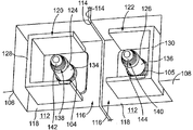
도 1은 예시적인 일 실시예에 따라 형성된 커넥터 시스템(100)을 도시한다. 커넥터 시스템(100)은, 배터리들(106, 108) 등의 부품들의 (도 2에 도시한) 전력 단자들(104, 105)을 전기적으로 접속하는 데 유연한 다층 버스 바를 이용하는 전력 단자 커넥터(102)를 포함한다. 동 도에 도시한 전력 단자 커넥터(102)는 예시적인 일 실시예를 도시한 것이지만, 대체 실시예들에서는 다른 형상, 부품, 또는 특징부를 가질 수도 있다. 전력 단자 커넥터(102)는 배터리들(106, 108)을 전기적으로 접속한다. 전력 단자 커넥터(102)는, 배터리들(106, 108)을 상호 접속하는 버스 또는 점퍼를 나타낸다. 배터리들(106, 108)은 차량에서 사용되는 임의의 전압 배터리일 수 있다. 선택 사항으로, 차량은 전기 차량 또는 하이브리드 전기 차량일 수 있고, 배터리들(106, 108)은 전기 차량 또는 하이브리드 전기 차량을 위한 전력 시스템의 일부로서 사용될 수 있다.FIG. 1 illustrates a
전력 단자 커넥터(102)는, (도 2에 도시한) 전력 단자들(104, 105)에 쉽고도 빠르게 종단될 수 있는 빠른 접속 빠른 접속 해제형 커넥터이다. 전력 단자 커넥터(102)는 배터리들(106, 108) 주변의 공간을 보존하도록 매우 작은 프로파일을 갖는다. 대체 실시예들에서는, 배터리들(106, 108) 또는 다른 전기 부품들을 상호 접속하는 데 유연한 버스 바를 사용하는 다른 유형의 전력 단자 커넥터들을 사용할 수도 있다.The
배터리들(106, 108)의 각각은, 상부(110), 상부(110)에 수직인 정면(112), 및 상부(110)와 정면(112)에 수직인 측면(114)을 포함한다. 배터리들(106, 108)의 측면들(114)은 서로 대면한다. 상부(100), 정면(112), 및 측면(114)은 배터리(106, 108)의 코너에서 대략 만난다. 예시적인 일 실시예에서, 배터리(106, 108)는 코너에서 노치 아웃 영역(notched-out area; 116)을 포함한다. 노치 아웃 영역(116)은, 상부(110) 아래로, 정면(112) 뒤로, 측면(114)으로부터 내측으로 오목하다. 노치 아웃 영역(116)은 상부(110), 정면(112), 및 측면(114)을 따라 연장되는 면들에 의해 형성되는 윈도우(window) 또는 엔벨로프(envelope)를 형성한다.Each of the batteries 106,108 includes an
전력 단자 커넥터(102)는, 배터리들(106, 108)의 측면들(114) 간의 계면에 걸쳐 이어지며, 노치 아웃 영역들(116) 모두에 위치한다. 배터리들(106, 108)은 노치 아웃 영역(116)의 하부에서 장착 패드(118)를 포함한다. (도 2에 도시한) 전력 단자들(104, 105)은 대응하는 장착 패드(118)로부터 연장된다. 예시적인 일 실시예에서, 전력 단자 커넥터(102)는 배터리들(106, 108) 간의 상대 이동을 가능하게 하는 유연한 커넥터이다. 전력 단자 커넥터(102)는, 측면들(114) 간의 계면에 걸쳐 이어지며, 진동 및 이와 유사한 것들로부터 배터리들(106, 108) 간의 다른 간격, 배터리들(106, 108)의 이동 등을 수용한다.The
제1 헤더(120)는 제1 배터리(106)의 장착 패드(118)에 결합되고, 제2 헤더(122)는 제2 배터리(108)의 장착 패드(118)에 결합된다. 전력 단자 커넥터(102)는 헤더들(120, 122)에 결합된다. 예시적인 일 실시예에서, 헤더들(120, 122)은, 헤더들(120, 122)이 상부(110), 정면(112), 또는 측면(114)을 벗어나 연장되지 않도록 노치 아웃 영역들(116) 내에 수용된다. 전력 단자 커넥터(102)는, 전력 단자 커넥터(102)가 배터리들(106, 108)의 상부들(110)을 벗어나(예를 들어, 상부들 위로) 연장되지 않도록 헤더들(120, 122)에 결합된다. 전력 단자 커넥터(102)는, 전력 단자 커넥터(102)가 배터리들(106, 108)의 정면들(112)을 벗어나(예를 들어, 정면들로부터 외측으로) 연장되지 않도록 헤더들(120, 122)에 결합된다. 이처럼, 다른 배터리 등의 기타 부품들은, 헤더들(120, 122) 또는 전력 단자 커넥터(102)로부터의 간섭 없이 배터리들(106, 108)의 바로 앞에 위치할 수 있다. 커버 또는 리드 등의 다른 부품은, 헤더들(120, 122) 또는 전력 단자 커넥터(102)로부터의 간섭 없이 배터리들(106, 108)의 상부들(110)을 따라 연장될 수 있다. 대체 실시예에서, 배터리들(106, 108)은 노치 아웃 영역들(118)을 포함하지 않을 수 있고, 대신에, 헤더들(120, 122)이 배터리들(106, 108)의 상부들(110) 상에 제공될 수 있다.The
도 2는, 헤더들(120, 122)이 대응하는 노치 아웃 영역들(116)에서 배터리들(106, 108)에 결합된 노치 아웃 영역들(116)을 나타내는 배터리들(106, 108)의 일부를 도시한다. 예시적인 일 실시예에서, 헤더들(120, 122)은, (도 1에 도시한) 전력 단자 커넥터(102)를 위한 계면을 제공하는 배터리들(106, 108)의 고정된 커넥터들이다. 헤더들(120, 122)은 전력 단자들(104, 105)을 각각 포함한다.Figure 2 illustrates a portion of the batteries 106,108 that represent the notch-out
전력 단자들(104, 105)은, 배터리들(106, 108)로부터 연장되며 배터리들에 전기적으로 결합되는 핀들(124, 126)을 각각 포함한다. 핀들(124, 126)은 핀 축들(예를 들어, 팁들로부터 핀들(124, 126)의 베이스들로 연장되는 중심 축들)을 따라 연장된다. 선택 사항으로, 핀들(124, 126)은 정면들(112)과 측면들(114)에 대략 평행하게 연장될 수 있다. 핀들(124, 126)은 장착 패드들(118)로부터 연장된다.
헤더들(120, 121)은 전력 단자들(104, 105)을 부분적으로 둘러싸는 헤더 슈라우드들(128, 130)을 포함한다. 헤더 슈라우드들(128, 130)은 슈라우드 벽들에 의해 형성된다. 예시적인 일 실시예에서, 슈라우드 벽들은 박스 형상일 수 있다. 헤더 슈라우드들(header shrouds; 128, 130)은 개방된 상부들과 개방된 정면측들을 가질 수 있다. 예시적인 일 실시예에서, 슈라우드 벽들은, 비전도성이며, 전력 단자들(104, 105)의 우연한 접촉을 방지한다.
핀들(124, 126)은 외측 접촉면들(134, 136)을 포함한다. 핀들(124, 126)은 핀들의 원단부들 근처에 홈들(138, 140)을 갖는다. 핀 헤드들(142, 144)은, 핀들(124, 126)이 홈들(138, 140) 위에서 더욱 큰 직경 부분을 갖도록 홈들(138, 140) 위에 형성된다. 홈들(138, 140)은 핀들(124, 126)의 더욱 작은 직경 부분이다. 선택 사항으로, 핀 헤드들(142, 144)은 핀들(124, 126)이 터치되지 않게 하는 플라스틱 캡들이다.The
조립 동안, 전력 단자 커넥터(102)는 헤더 슈라우드들의 개방된 상부들을 통해 헤더 슈라우드들(128, 130) 내로 로딩된다. 전력 단자 커넥터(102)가 전력 단자들(104, 105)에 접속되면, 전력 단자 커넥터(102)는 전력 단자들(104, 105)을 전기적으로 접속한다. 전력 단자 커넥터(102)가 핀들(124, 126)에 결합되면, 전력 단자 커넥터(102)의 일부들은, 전력 단자 커넥터(102)를 핀들(124, 126)에 고정하도록 홈들(138, 140)에 수용된다. 예시적인 일 실시예에서, 전력 단자 커넥터(102)는 핀들(124, 126)로부터 우연히 해제될 수 없다. 대신에, 신중하게 액션을 취하여 전력 단자 커넥터(102)를 홈들(138, 140)로부터 해제하고, 그후, 전력 단자 커넥터(102)는 핀 축들에 평행한 방향으로 핀들(124, 126)로부터 분리되어 들어올려질 수 있다. 전력 단자 커넥터(102)는 핀들(124, 126)에 빠르고도 쉽게 결합될 수 있는 빠른 접속형 커넥터이다. 전력 단자 커넥터(102)는 임의의 도구 사용 없이 핀들(124, 126)에 결합될 수 있다. 전력 단자 커넥터(102)는, 임의의 다른 기동, 잠금, 또는 래칭을 필요로 하지 않고서 하측 방향으로 전력 단자 커넥터(102)를 핀들(124, 1246) 상으로 간단히 가압함으로써 결합될 수 있다.During assembly, the
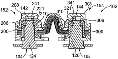
도 3은 전력 단자 커넥터(102)의 분해도이다. 전력 단자 커넥터(102)는, 다층 버스 바(150), 다층 버스 바(150)에 결합된 제1 단자 조립체(152), 및 다층 버스 바(150)에 결합된 제2 단자 조립체(154)를 포함한다. 제1 단자 조립체(152)는 (도 2에 도시한) 제1 핀(124)에 결합되도록 구성된다. 제2 단자 조립체(154)는 (도 2에 도시한) 제2 핀(126)에 결합되도록 구성된다. 선택 사항으로, 도 12와 도 13에 예시한 바와 같은 실시예들에서는, 다층 버스 바들을 사용하여 제1 및 제2 핀들(124, 126)을 상호 접속할 수 있다. 제1 및 제2 단자 조립체들(152, 154)은, 대응하는 전력 단자들(104, 105)의 핀들(124, 125; 도 2에 도시됨)에 분리가능하게 결합되도록 구성된 빠른 접속 조립체들이다. 대체 실시예들에서는, 전력 단자들(104, 105)을 상호 접속하도록 다른 유형의 단자 조립체들을 다층 버스 바(150)와 함께 사용될 수 있다.3 is an exploded view of the
다층 버스 바(150)는, 제1 장착부(160), 제2 장착부(162), 및 제1 및 제2 장착부들(160, 162) 간의 유연부(164)를 포함한다. 제1 단자 조립체(152)는 제1 장착부(160)에 결합된다. 제2 단자 조립체(154)는 제2 장착부(162)에 결합된다. 예시적인 일 실시예에서, 제1 장착부(160), 제2 장착부(162), 및/또는 유연부(164)는 적층 구성으로 금속 시트들의 다수의 층들을 갖는다. 선택 사항으로, 이 층들이 라미네이팅될 수 있다. 유연부(164)는 형상을 변경하여 제1 및 제2 장착부들(160, 162)의 상대 위치를 변경하도록 구성된다. 유연부(164)는 제2 장착부(162)에 대하여 제1 장착부(160)를 가변적으로 위치시키도록 길어지거나 짧아질 수 있다. 다층 버스 바(150)는 도전성을 갖는다. 예시적인 일 실시예에서, 다층 버스 바(150)는 구리로 제조되지만, 대체 실시예들에서는 다른 재료를 사용할 수도 있다. 예시적인 일 실시예에서, 제1 장착부(160), 제2 장착부(162), 및 유연부(164)는 구리의 단일 부품으로 일체형으로 형성된다. 선택 사항으로, 구리의 단일 부품보다 많은 부품을 사용하여 구리의 다수의 시트들 등의 버스 바를 형성할 수도 있다. 제1 장착부(160), 제2 장착부(162), 및 유연부(164)는 다층 구조일 수도 있다.The
제1 단자 조립체(152)는, 다층 버스 바(150)와 핀(124)에 전기적으로 접속되도록 구성된 단자 본체(200)를 포함한다. 예시적인 일 실시예에서, 단자 본체(200)는 다층 버스 바(150)로부터 별도로 제공되며 이러한 다층 버스 바에 결합된다. 제1 단자 조립체(152)는 단자 본체(200) 내에 수용되는 컨택트 스프링(202)을 포함한다. 컨택트 스프링(202)은 단자 본체(200)를 핀(124)에 전기적으로 접속하는 데 사용된다. 제1 단자 조립체(152)는, 단자 본체(200)와 제1 장착부(160)를 수용하고 적어도 부분적으로 둘러싸는 하우징(204)을 포함한다. 하우징(204)은, 사람을 손상시킬 수 있는 전기 쇼크를 야기할 수 있는 사람이나 도구에 의한 우연한 접촉으로부터 다층 버스 바(150)와 단자 본체(200)를 보호한다.The first
제1 단자 조립체(152)는 전력 단자 커넥터(102)를 핀(124)에 고정하는 데 사용되는 스프링 클립(206)을 포함한다. 제1 단자 조립체(152)는, 단자 본체(200)에 회전가능하게 결합되도록 구성된 캡(208)을 포함한다. 캡(208)은, 이하에서 더욱 상세히 설명하는 바와 같이, 스프링 클립(206)을 기동하여 전력 단자 커넥터(102)를 핀(124)으로부터 잠금 해제하도록 사용된다. 캡(208)은, 대체 실시예들에서는 회전이 아닌 수단에 의해, 예를 들어, 캡을 선형 방향으로 가압함으로써, 기동되도록 구성될 수 있다. 캡(208), 스프링 클립(206), 하우징(204), 및/또는 단자 본체(200) 간의 상호 작용은 이러한 대체 실시예들에서 다를 수도 있다.The first
단자 본체(200)는 핀(124)을 수용하도록 구성된 소켓(210)을 포함한다. 소켓(210)은 중공 챔버(220)를 포함한다. 선택 사항으로, 챔버(220)는 소켓(210)의 하단부를 통해 핀(124)을 수용하도록 챔버의 양단부에서 개방될 수 있다. 예시적인 일 실시예에서, 챔버(220)를 형성하는 소켓(210)의 외면과 내면은 대략 원통 형상이다. 대체 실시예들에서는 다른 형상도 가능하다. 챔버(220)는 핀(124)과 정합하도록 컨택트 스프링(202)을 내부에 수용한다.The
소켓(210)의 상부는 스프링 클립(206)의 일부를 수용하는 포켓(222)을 포함한다. 예시한 실시예에서, 포켓(222)은 소켓(210)의 상부에 제공되고, 소켓(210)의 길이 방향 축에 대략 평행하게 연장된다. 포켓(222)은 스프링 클립(206)의 단부를 단자 본체(200)에 대하여 제 위치에 유지하도록 스프링 클립(206)의 단부를 수용한다.The upper portion of the
컨택트 스프링(202)은 제1 단부(224)와 제2 단부(226) 간에 연장된다. 컨택트 스프링(202)은 제1 단부(224)에서 원주 밴드(circumferential band)를 갖고 제2 단부(226)에서 다른 원주 밴드를 갖는다. 복수의 스프링 빔(228)은 제1 및 제2 단부들(224, 226)에서 원주 밴들 간에 연장된다. 예시한 실시예에서, 스프링 빔들(228)은 컨택트 스프링(202)의 중간을 향하여 내측으로 테이퍼링된다. 컨택트 스프링(202)은 컨택트 스프링(202)의 중간에서 넥다운된다(necked-down). 컨택트 스프링(202)은 컨택트 스프링(202)의 중간에서 더욱 작은 직경을 갖고 제1 및 제2 단부들(224, 226)에서 더욱 큰 직경들을 갖는다. 컨택트 스프링(202)의 넥다운 부분은 핀(124)과 체결하도록 구성된다. 제1 및 제2 단부들(224, 226)은, 컨택트 스프링(202)이 챔버(220) 내로 로딩되면 소켓(210)과 체결하도록 구성된다. 예시적인 일 실시예에서, 스프링 빔들(228)은, 편향가능하며, 핀(124)이 컨택트 스프링(202) 내로 로딩되면 외측으로 편향될 수 있다. 컨택트 스프링(202)은 핀(124)과 단자 본체(200) 간에 전기적 경로를 형성한다.The
스프링 클립(206)은 곡선 형상을 갖고, 제1 단부(230)와 제2 단부(232) 간에 연장된다. 스프링 클립(206)은 개방측(234)에서 제1 및 제2 단부들(230, 232)이 서로 대향하는 개방측(234)을 갖는다. 스프링 클립(206)은 개방측(234)에 대향하는 폐쇄측(236)을 갖는다. 스프링 클립(206)은 폐쇄측(236)에서 연결된 제1 암(arm; 238)과 제2 암(240)을 갖는다. 제1 암(238)은 제1 단부(230)로 연장된다. 제2 암(240)은 제2 단부(232)로 연장된다. 개구부(241)는 제1 및 제2 암들(238, 240) 간에 생성된다.The
예시적인 일 실시예에서, 제1 및 제2 단부들(230, 232)은 제1 및 제2 암들(238, 240)을 서로 멀어지게 벌리도록 서로 멀어지며 이동할 수 있다. 제1 및 제2 암들(238, 240)이 서로 멀어지며 벌어지면, 이들 간의 개구부(241)의 크기가 확대된다.In an exemplary embodiment, the first and second ends 230 and 232 are movable away from each other to spread the first and
스프링 클립(206)은 잠금 위치와 이격 위치(clearance position) 간에 이동가능하다. 스프링 클립(206)은, 전력 단자 커넥터(102)를 전력 단자(104)에 고정하기 위해 잠금 위치에서 핀(124)과 체결하도록 구성된다. 스프링 클립(206)은 이격 위치에서 핀(124)으로부터 체결 해제되도록 구성된다. 선택 사항으로, 잠금 위치에서, 제1 및 제2 단부들(230, 232)은 서로 상당히 가깝게 위치한다. 제1 및/또는 제 2 단부들(230, 232)은, 스프링 클립(206)이 이격 위치로 이동함에 따라 스프링 클립(206)의 개구부의 크기를 확대하도록 서로 멀어지며 이동한다. 스프링 클립(206)은, 스프링 클립(206)이 잠금 위치로부터 이격 위치로 이동함에 따라 탄성적으로 변형된다. 제1 및 제2 단부들(230, 232)이 강제적으로 더 이상 서로 멀어지지 않으면, 스프링 클립(206)은 정상적인 잠금 위치로 복귀한다.The
예시적인 일 실시예에서, 제1 단부(230)는 단자 본체(200)에 단단히 결합되도록 구성된다. 예시적인 일 실시예에서, 제1 단부(230)는 포켓(222) 내에 수용되도록 구성된다. 제1 단부(230)는, 제1 단부(230)가 포켓(222) 내에 수용되면 소켓(210)에 대하여 제 위치에서 고정된다. 제2 단부(232)는 캡(208)에 결합되도록 구성된다. 캡(208)이 회전함에 따라, 제2 단부(232)가 제1 단부(230)에 대하여 이동하게 되어 스프링 클립(206)이 잠금 위치로부터 이격 위치로 이동한다. 캡(208)이 회전하면, 제1 단부(230)가 포켓(222)에 고정되어 있기 때문에 스프링 클립(206)의 링 형상을 개방하거나 확대하게 된다.In an exemplary embodiment, the
예시한 실시예에서, 제2 단부(232)는 방사상 외측으로 연장되는 한편, 제1 단부(230)는 축방향 외측으로 연장된다. 제1 단부(230)는 제2 단부(232)에 대하여 대략 수직으로 배향된다. 대체 실시예들에서는 제1 및 제2 단부들(230, 232)의 다른 배향도 가능하다. 제1 단부(230)는 대체 실시예들에서 대체 수단에 의해 단자 본체(200)에 고정될 수 있다.In the illustrated embodiment, the
캡(208)은 상부(242)와 하부(244)를 포함한다. 캡(208)은 중공이며, 소켓(210) 위로 배치되도록 구성된다. 캡(208)은 하부(244)에서 림(rim; 246)을 포함한다. 캡(208)은 단자 본체(200)에 회전가능하게 결합되도록 구성된다. 예시적인 일 실시예에서, 하우징(204)은 캡(208)을 단자 본체(200)와 스프링 클립(206)에 대하여 제 위치에 고정하도록 사용된다. 캡(208)은 하우징(204)에 대하여 회전가능하다.The
하우징(204)은 다층 버스 바(150) 및/또는 단자 본체(200)에 결합된다. 하우징(204)은 플라스틱 재료 등의 유전 재료로 제조된다. 하우징(204)은 제1 장착부(160)를 내부에 수용하는 챔버(250)를 포함한다. 챔버(250)는 다층 버스 바(150)를 하우징(204) 내로 로딩하도록 하우징(204)의 일측에서 개방된다. 하우징(204)의 하부에 있는 개구부(252)는 단자 본체(200)와 정렬되어 핀(124)이 하우징(204)을 관통하여 단자 본체(200) 내로 향하게 할 수 있도록 구성된다. 하우징(204)은, 사람이나 도구, 와이어 등의 기타 부품에 의한 다층 버스 바(150)와 단자 본체(200)의 우연한 접촉을 방지하도록 다층 버스 바(150)를 덮고 단자 본체(200)를 둘러싼다.The
예시적인 일 실시예에서, 하우징(204)은, 캡(208)을 캡처하고 다층 버스 바(150)와 단자 본체(200)를 완전히 둘러싸 전력 단자 커넥터(102)를 접촉으로부터 보호하도록 유연부(164) 위에 배치된 스페이서(260)와 협동한다. 스페이서(260)는 소켓(210) 옆을 따라 연장된다. 스페이서(260)는 캡(208)을 다층 버스 바(150) 상의 제 위치에 유지하는 데 사용되는 탭(262)을 포함한다. 예를 들어, 캡(208)의 림(246)은 탭(262) 아래에서 캡처된다.In an exemplary embodiment, the
하우징(204)은, 캡(208)의 림(246)을 수용하도록 구성된 포켓(264)을 포함한다. 캡(208)은 캡(208)을 다층 버스 바(150)와 단자 본체(200) 위에 고정하도록 포켓(264) 내에 캡처된다. 캡(208)은 포켓(264) 내에서 그리고 탭(262) 아래에서 회전가능하다.The
제2 단자 조립체(154)는 제1 단자 조립체(152)와 유사하지만, 제2 장착부(162)에 결합된다. 제2 단자 조립체(154)는 다층 버스 바(150)와 핀(126)에 전기적으로 접속되도록 구성된 단자 본체(300)를 포함한다. 예시적인 일 실시예에서, 단자 본체(300)는 다층 버스 바(150)로부터 별도로 제공되며 다층 버스 바에 결합된다. 제2 단자 조립체(154)는 단자 본체(300) 내에 수용되는 컨택트 스프링(302)을 포함한다. 제2 단자 조립체(154)는 단자 본체(300)와 제2 장착부(162)를 적어도 부분적으로 둘러싸며 수용하는 하우징(304)을 포함한다. 제2 단자 조립체(154)는 전력 단자 커넥터(102)를 핀(126)에 고정하는 데 사용되는 스프링 클립(306)을 포함한다. 제2 단자 조립체(154)는 단자 본체(300)에 회전가능하게 결합되도록 구성된 캡(308)을 포함한다. 캡(308)은 스프링 클립(306)을 기동시켜 전력 단자 커넥터(102)를 핀(126)으로부터 잠금 해제하는 데 사용된다.The second
단자 본체(300)는 중공 챔버(320)를 갖는 소켓(310)을 포함한다. 소켓(310)의 상부는 스프링 클립(306)의 일부를 수용하는 포켓(322)을 포함한다. 컨택트 스프링(302)은 챔버(320) 내에 수용된다. 컨택트 스프링(302)은 컨택트 스프링(202)과 동일할 수 있다.The
스프링 클립(306)은 스프링 클립(206)과 동일할 수 있다. 스프링 클립(306)은 제1 단부(330)와 제2 단부(332) 간에 연장된다. 스프링 클립(306)은 개방측(334), 폐쇄측(336), 제1 암(338), 및 제2 암(340)을 갖는다. 개구부(341)는 제1 및 제2 암들(338, 340)간에 생성된다. 스프링 클립(306)은 잠금 위치와 이격 위치 간에 이동가능하다. 스프링 클립(306)은 전력 단자 커넥터(102)를 전력 단자(105)에 고정하기 위해 잠금 위치에서 핀(126)과 체결하도록 구성된다. 스프링 클립(306)은 이격 위치에서 핀(126)으로부터 체결 해제되도록 구성된다.The
캡(308)은 하부(344)에서의 림(346)과 함께 상부(342)와 하부(344)를 포함한다. 캡(308)은 단자 본체(300)에 회전가능하게 결합되도록 구성된다.The
하우징(304)은 제2 장착부(162)를 내부에 수용하는 챔버(350)를 포함한다. 하우징(304)의 하부에 있는 개구부(352)는, 단자 본체(300)와 정렬되어 핀(126)이 하우징(304)을 관통하여 단자 본체(300)로 향하게 할 수 있도록 구성된다. 하우징(304)은 스페이서(260)와 협동하여 캡(308)을 캡처한다. 스페이서(260)는 캡(308)을 다층 버스 바(150) 상의 제 위치에서 유지하는 데 사용되는 탭(362)을 포함한다. 하우징(304)은 캡(308)의 림(346)을 수용하도록 구성된 포켓(364)을 포함한다. 캡(308)은 포켓(364) 내에서 그리고 탭(362) 아래에서 회전가능하다.The
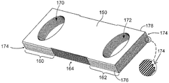
도 4는 미리 형성된 구성의 다층 버스 바(150)의 상부 사시도이다. 제1 장착부(160)는 제1 장착부를 통해 연장되는 개구부(170)를 포함한다. 제2 장착부(162)는 제2 장착부를 통해 연장되는 개구부(172)를 포함한다. 개구부들(170, 172)은 (이들 모두가 도 3에 도시한) 단자 본체들(200, 300)을 수용하도록 구성된다.4 is a top perspective view of a
예시적인 일 실시예에서, 다층 버스 바(150)는, 얇은 구리 시트로 제조된다. 구리 시트는 제1 장착부(160), 제2 장착부(162), 및 유연부(164)를 잇기 위해 적층 구성으로 구리 시트들의 다수의 층들을 형성하도록 여러 번 접힐 수 있다. 선택 사항으로, 구리 시트들은 라미네이팅될 수도 있다. 접힘부(174)는 구리 시트의 각각의 접힘 부분에서 형성된다. 접힘부들(174)은 다층 버스 바(150)의 측면들(176, 178)에 위치한다. 예시한 실시예에서, 구리 시트는 약 15회 접혀 구리 시트들의 약 16개의 층을 형성하지만, 임의의 복수회로 유연 시트를 접을 수도 있다. 선택 사항으로, 구리 시트들의 층들 간의 상대 이동을 허용하도록 각 층 간에 갭들을 제공할 수 있고, 다층 버스 바(150)가 유연해지게, 예를 들어, 다층 버스 바(150)를 길어지게 또는 짧아지게 구부릴 수 있다. 갭들은 얇을 수 있다. 예를 들어, 갭들은 구리 시트의 하나의 층의 두께보다 얇을 수 있다.In an exemplary embodiment, the
개구부들(170, 172)은 모든 층들을 통해 연장된다. 층들의 개수를 증가시킴으로써 다층 버스 바(150)의 전류 전달 능력이 증가된다. 여러 번 접히는 이러한 얇은 구리 시트를 사용함으로써, 다층 버스 바(150)의 전체 두께에 상관없이 유연부(164)가 유연한 상태로 유지될 수 있다. 예를 들어, 각 층은 상대적으로 얇고 유연하게 유지되지만, 다수의 그러한 층을 준비함으로써, 제1 장착부(160)와 제2 장착부(162) 간에 전류를 전달하는 구리의 총량을 증가시킨다. 예시적인 일 실시예에서, 접힘부들(174)은 제1 장착부(160)와 제2 장착부(162)를 따라 다층 버스 바(150)의 측면들(176, 178)을 따라 온전한 상태(intact)로 유지된다. 그러나, 접힘부들(174)은 유연부(164) 내에서 측면들(176, 178)을 따라 제거되어, 개별적인 시트 층들을 서로 분리함으로써 유연부(164)가 더욱 유연해지게 한다.The
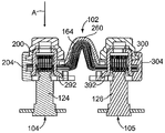
도 5는 다층 버스 바(150)에 결합된 단자 본체들(200, 300)과 함께 다층 버스 바(150)를 도시하는 전력 단자 커넥터(102)의 일부의 단면도이다. 유연부(164)는 휘어진 상태로 도시되어 있으며, 유연부(164)가 비교적 평평한 경우에 제1 장착부(160)를 제2 장착부(162)에 더욱 가깝게 위치한다. 예시한 실시예에서, 유연부(164) 제1 레그(180)와 제2 레그(182)에 의해 형성된 V 형상으로 정의된다. 제1 및 제2 레그들(180, 182)은 제1 장착부(160)와 제2 장착부(162)의 축 방향을 가변하도록 서로에 대하여 이동가능하다.5 is a cross-sectional view of a portion of the
단자 본체들(200, 300)은 개구부들(170, 172)을 통해 다층 버스 바(150) 내로 각각 로딩된다. 예시적인 일 실시예에서, 단자 본체들(200, 300)은 억지 끼워맞춤에 의해 다층 버스 바(150) 내에 유지된다. 단자 본체들(200, 300)의 외면은 다층 버스 바(150)의 구리 시트의 층들의 각각과 직접 체결하고, 이러한 층들의 각각에 전기적으로 접속된다. 예시적인 일 실시예에서, 단자 본체들(200, 300)은 단자 본체들(200, 300)의 하부에서 플랜지들(190, 192)을 각각 포함한다. 플랜지들(190, 192)은 다층 버스 바(150)의 하부와 체결하여 단자 본체들(200, 300)을 다층 버스 바(150)에 각각 전기적으로 접속한다. 플랜지들(190, 192)은 단자 본체들(200, 300)이 다층 버스 바(150) 내로 로딩되는 것에 대한 정지부 또는 제한부를 형성한다. 단자 본체들(200, 300)의 상측 부분들은 다층 버스 바(150)를 통해 연장되고, 다층 버스 바(150)의 상면으로부터 상측으로 연장된다. 단자 본체들(200, 300)의 상측 부분들은, (모두 도 3에 도시한) 하우징들(204, 304)과 (모두 도 3에 도시한) 캡들(208, 308) 내로 로딩되도록 구성된다. 스프링 클립들(206, 306)은 (모두 도 2에 도시한) 핀들(124, 126)과 각각 체결하도록 단자 본체들(200, 300) 내에 각각 배치된다.The
도 6은 스프링 클립(206)이 내부에 수용된 캡(208)의 하면도이다. 스프링 클립(206)의 제2 단부(232)는 캡(208)의 포켓(290) 내에 캡처된다. 제2 단부(232)는 캡(208)에 대하여 제 위치에 고정되고, 캡(208)의 회전은, 제2 단부(232)를 제1 단부(230)로부터 멀어지며 이동시켜 스프링 클립(206)의 링 형상을 개방하거나 확대하고, 이에 따라 스프링 클립(206)이 핀(124)으로부터 체결 해제될 수 있다.6 is a bottom view of the
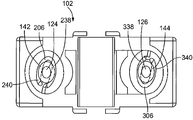
도 7은 명료함을 위해 (모두 도 3에 도시한) 캡들(208, 308)이 제거된 전력 단자 커넥터(102)의 상면도이다. 스프링 클립들(206, 306)은 핀들(124, 126)에 대하여 잠금 위치에 있는 것으로 도시되어 있다. 스프링 클립(206)의 제1 및 제2 암들(238, 240)은 핀 헤드(142) 아래의 핀 (124)의 (도 2에 도시한) 홈(138) 내에 수용된다. 스프링 클립(206)은 핀(124) 상으로 잠궈진다. 스프링 클립(306)의 제1 및 제2 암들(338, 340)은 핀 헤드(144) 아래의 핀(126)의 (도 2에 도시한) 홈(140) 내에 수용된다. 스프링 클립(306)은 핀(126) 상으로 잠궈진다.7 is a top view of the
도 8은 전력 단자들(104, 105)에 결합되는 전력 단자 커넥터(102)의 단면도이다. 전력 단자 커넥터(102)는, 대략 핀 축들을 따라, 예를 들어, 화살표 A로 도시한 로딩 방향으로, 핀들(124, 126) 상으로 로딩된다. 단자 본체들(200, 300)은 핀들(124, 126)과 정렬된다. 유연부(164)는 단자 본체들(200, 300)이 거리 범위에서 축 방향으로 이격되게 하여 핀들(124, 126)과 적절히 정렬될 수 있게 한다. 스페이서(260)는 유연부(164)를 덮고, 유연부(164)는 스페이서(260) 아래의 영역 내에서 이동가능하다.8 is a cross-sectional view of a
예시적인 일 실시예에서, 단자 본체(200)는 단자 본체로부터 하측으로 연장되는 잠금 랜스(locking lance; 292)를 포함한다. 잠금 랜스(292)는 단자 본체(200)를 하우징(204) 내에 고정하도록 하우징(204) 내의 대응하는 개구부 내로 연장된다. 단자 본체(300)는 단자 본체로부터 하측으로 연장되는 잠금 랜스(392)를 포함한다. 잠금 랜스(392)는 단자 본체(300)를 하우징(304) 내에 고정하도록 하우징(304) 내의 대응하는 개구부 내로 연장된다. In one exemplary embodiment, the
도 9는 전력 단자들(104, 105)에 결합되는 전력 단자 커넥터(102)의 단면도이다. 도 9는 조립의 중간 단계를 도시한다. 전력 단자 커넥터(102)는 전력 단자들(104, 105)에 전기적으로 접속되지만, 전력 단자 커넥터(102)가 미설치(unseated) 위치에 있다. 전력 단자 커넥터(102)는 적절히 사용하기 위해서는 완전하게 설치 및 잠금 상태로 되어야 한다.9 is a cross-sectional view of a
미설치 위치에서, 전력 단자 커넥터(102)는, 핀들(124, 126)이 단자 본체들(200, 300) 내에 수용되도록 핀들(124, 126) 상으로 로딩된다. 핀들(124, 126)은 소켓들(210, 310)의 상측 개구부들(221, 321)을 통해 연장된다. 스프링 클립들(206, 306)은, 핀들(124, 126)의 원단부들에 간섭하여, 핀들(124, 126)이 전력 단자 커넥터(102)에 완전히 로딩되는 것을 정지시킨다. 스프링 클립(206)의 제1 및 제2 암들(238, 240) 간의 개구부의 폭은 핀 헤드(142)의 직경보다 좁다. 스프링 클립(306)의 제1 및 제2 암들(338, 340) 간의 개구부의 폭은 핀 헤드(144)의 직경보다 좁다. 핀들(124, 126)이 스프링 클립들(206, 306)을 관통하고 이에 따라 전력 단자 커넥터(102)가 완전 설치 위치로 이동할 수 있게 하려면, 스프링 클립들(206, 306)이 이격 위치로 이동해야 한다. 캡들(208, 308)을 회전시켜 제2 단부들(232, 332)(모두 도 3에 도시함)을 제1 단부들(230, 330)(모두 도 3에 도시함)에 대하여 이동시켜 제2 암들(240, 340)을 제1 암들(238, 338)로부터 벌려 개구부들(241, 341)을 넓게 하고, 이에 따라 전력 단자 커넥터(102)가 핀들(124, 126) 상에 완전하게 설치될 수 있다.In the unfinished position, the
캡들(208, 308)은 전력 단자 커넥터(102)를 설치하도록 다른 방식으로 이동할 수 있다. 예를 들어, 캡들(208, 308)을, 더욱 일반적으로는, 제1 및 제2 단자 조립체들(152, 154)을 하측으로 가압하여 전력 단자 커넥터(102)에 수직 하향력을 인가할 수 있고, 이는 스프링 클립들(206, 306)이 핀 헤드들(142, 144)로부터 벗어날 때까지 스프링 클립들(206, 306)이 핀들(124, 126)의 큰 반경을 따라 슬라이딩하게 할 수 있다. 전력 단자 커넥터(102)를 핀(124) 상으로 수직 하향 방향으로 누르는 경우에 스프링 클립(206)이 핀들(124, 126)과의 상호 작용에 의해 이격 위치로 벌어질 수 있다. 제1 및 제2 단자 조립체들(152, 154)은, 캡들(208, 308)을 회전시키거나 또는 스프링 클립들(206, 306)을 이격 위치로 이동시키려는 스프링 클립력(clip force)을 간단히 극복하여 제1 및 제2 단자 조립체들(152, 154)을 핀들(124, 126) 상으로 가압함으로써 핀들(124, 126)에 빠르게 접속될 수 있다.
도 10은 전력 단자들(104, 105) 상에 설치되어 잠금 상태에 있는 전력 단자 커넥터(102)의 단면도이다. 완전 설치 상태에서, 핀들(124, 126)은 단자 본체들(200, 300) 내로 완전하게 로딩되어 있다. 컨택트 스프링들(202, 302)은 핀들(124, 126)의 접촉면들(136)과 체결한다. 컨택트 스프링들(202, 302)은 핀들(124, 126)과 단자 본체들(200, 300)을 각각 전기적으로 상호 접속한다. 핀 헤드들(142, 144)은 상측 개구부들(221, 321)을 통해 그리고 스프링 클립들(206, 306)을 통해 캡들(208, 308) 내로 연장된다. 설치 상태에서, 스프링 클립들(206, 306)은 홈들(138, 140) 내에 캡처된다.10 is a cross-sectional view of the
스프링 클립(206)은 잠금 위치에 있고, 이 위치에서, 제1 및 제2 암들(238, 240)은, 핀 헤드(142) 아래에서 핀 헤드(142)보다 작은 반경을 갖는 홈(138) 내에 위치한다. 핀 헤드(142)는 핀(124)에 대한 제1 단자 조립체(152)의 상대 위치를 잠그도록 스프링 클립(206)을 캡처한다. 스프링 클립(306)은 잠금 위치에 있고, 이 위치에서, 제1 및 제2 암들(338, 340)은, 핀 헤드(144) 아래에서 핀 헤드(144)보다 작은 반경을 갖는 홈(140) 내에 위치한다. 핀 헤드(144)는 핀(126)에 대한 제2 단자 조립체(154)의 상대 위치를 잠그도록 스프링 클립(306)을 캡처한다.The
스프링 클립들(206, 306)을 핀들(124, 126)로부터 잠금 해제하려면, 스프링 클립들(206, 306)을 이격 위치로 이동시켜야 한다. 예를 들어, 캡들(208, 308)을 회전시켜 제1 단부들(230, 330)에 대하여 제2 단부들(232, 332)(도 3에 도시함)을 회전시킬 수 있다. 캡(208, 308)이 회전함에 따라, 제2 암들(240, 340)이 제1 암들(238, 338)로부터 멀어지며 벌어지고 개구부들(241, 341)을 적어도 핀 헤드들(142, 144)만큼 넓게 한다. 스프링 클립들(206, 306)은 이격 위치에서 핀들(124, 126)로부터 체결 해제된다. 일단 전력 단자 커넥터(102)가 잠금 해제 위치에 있고 스프링 클립들(206, 306)이 이격 위치에 있으면, 핀 축들에 대략 평행한 방향으로, 예를 들어, 화살표 B의 방향으로 전력 단자 커넥터(102)를 핀들(124, 126)로부터 분리되도록 들어올림으로써 전력 단자 커넥터(102)를 핀들(124, 126)로부터 접속 해제할 수 있다.To unlock the spring clips 206, 306 from the
도 11은 예시적인 일 실시예에 따라 형성된 전력 단자 커넥터(402)의 측면 사시도이다. 전력 단자 커넥터(402)는, 다층 버스 바(450), 다층 버스 바(450)에 결합된 제1 단자 조립체(452), 및 다층 버스 바(450)에 결합된 제2 단자 조립체(454)를 포함한다. 제1 단자 조립체(452)는 (도 2에 도시한) 제1 핀(124)에 결합되도록 구성된다. 제2 단자 조립체(454)는 (도 2에 도시한) 제2 핀(126)에 결합되도록 구성된다. 다층 버스 바(450)는 유연하며, 서로 다양한 거리에 있을 수 있는 핀들(124, 126)에 장착하도록 제1 단자 조립체(452)와 제2 단자 조립체(454) 간의 상대 위치를 변경하기 위해 및/또는 핀들(124, 126)에 대한 접속 후 진동을 수용하기 위해 다층 버스 바(450)가 길어지거나 짧아질 수 있다.11 is a side perspective view of a
다층 버스 바(450)는 다층 버스 바(150)와 실질적으로 마찬가지일 수 있다. 다층 버스 바(450)는, 제1 장착부(460), 제2 장착부(462), 및 제1 및 제2 장착부들(460, 462) 간의 유연부(464)를 포함한다. 예시적인 일 실시예에서, 제1 장착부(460), 제2 장착부(462), 및/또는 유연부(464)는 적층 구성으로 금속 시트들의 다수의 층들을 갖는다. 유연부(464)는 형상을 변경하여 제1 및 제2 장착부들(460, 462)의 상대 위치를 변경하도록 구성된다. 다층 버스 바(450)는 도전성을 갖는다. 예시적인 일 실시예에서, 다층 버스 바(450)는 구리로 제조되지만, 대체 실시예들에서는 다른 재료를 사용할 수도 있다. 구리 시트는, 제1 장착부(460), 제2 장착부(462), 및 유연부(464)를 잇는 적층 구성으로 구리 시트들의 다수의 층들을 형성하도록 여러 번 접힌다.The
제1 단자 조립체(452)는, 다층 버스 바(450)와 핀(124)에 전기적으로 접속되도록 구성된 단자 본체(470)를 포함한다. 단자 본체(470)는 핀(124)을 수용하도록 구성된 소켓(472)을 포함한다. 단자 본체(470)는, 대체 실시예들에서는, 배터리 또는 다른 전기 부품에 핀과는 다른 유형의 단자가 제공되는 경우에 예를 들어 너트, 볼트, 블레이드, 핀, 또는 다른 유형의 커넥터를 사용하는 것을 포함하여 다른 수단에 의해 또는 다른 특징부를 사용하여 배터리에 종단될 수 있다. 선택 사항으로, 제1 단자 조립체(452)는 단자 본체(470)를 위한 하우징 또는 다른 커버링을 포함할 수도 있다. 하우징은 단자 본체(470)를 핀(124)에 위치시키고 및/또는 고정하는 데 사용될 수 있다.The first
제2 단자 조립체(454)는, 다층 버스 바(450)와 핀(126)에 전기적으로 접속되도록 구성된 단자 본체(480)를 포함한다. 단자 본체(480)는 핀(126)을 수용하도록 구성된 소켓(482)을 포함한다. 단자 본체(480)는, 대체 실시예들에서는, 배터리 또는 다른 전기 부품에 핀과는 다른 유형의 단자가 제공되는 경우에 예를 들어 너트, 볼트, 블레이드, 핀, 또는 다른 유형의 커넥터를 사용하는 것을 포함하여 다른 수단에 의해 또는 다른 특징부를 사용하여 배터리에 종단될 수 있다. 선택 사항으로, 제2 단자 조립체(454)는 단자 본체(480)를 위한 하우징 또는 다른 커버링을 포함할 수도 있다. 하우징은 단자 본체(480)를 핀(126)에 위치시키고 및/또는 고정하는 데 사용될 수 있다.The second
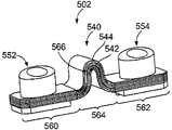
도 12는 예시적인 일 실시예에 따라 형성된 전력 단자 커넥터(502)의 측면 사시도이다. 전력 단자 커넥터(502)는 버스 바 조립체(540)를 포함한다. 버스 바 조립체(540)는 제1 다층 버스 바(542)와 제2 다층 버스 바(544)를 포함한다. 버스 바 조립체(540)는 2-적층 버스 바 조립체(two-stacked buss bar assembly)를 형성한다. 선택 사항으로, 제1 및 제2 다층 버스 바들(542, 544)은 서로 실질적으로 마찬가지일 수 있다. 다수의 다층 버스 바들(542, 544)을 버스 바 조립체(540) 내에 제공함으로써, 버스 바 조립체(540)가, 더욱 적은 개수의 층들을 갖는 버스 바 조립체보다 높은 전류를 도통할 수 있다.12 is a side perspective view of a
전력 단자 커넥터(502)는 버스 바 조립체(540)에 결합된 제1 단자 조립체(552) 및 버스 바 조립체(540)에 결합된 제2 단자 조립체(554)를 포함한다. 제1 및 제2 단자 조립체들(552, 554)은 (도 11에 도시한) 제1 및 제2 단자 조립체들(452, 454)과 실질적으로 마찬가지일 수 있다. 제1 단자 조립체(552)는 (도 2에 도시한) 제1 핀(124)에 결합되도록 구성된다. 제2 단자 조립체(554)는 (도 2에 도시한) 제2 핀(126)에 결합되도록 구성된다. 제1 및 제2 다층 버스 바들(542, 544)은, 유연하며, 서로 다양한 거리에 있을 수 있는 핀들(124, 126)에 장착하도록 제1 단자 조립체(552)와 제2 단자 조립체(554) 간의 상대 위치를 변경하기 위해 및/또는 핀들(124, 126)에 대한 접속 후 진동을 수용하기 위해 버스 바 조립체(540)를 길어지게 또는 짧아지게 할 수 있다.The
제1 및 제2 다층 버스 바들(542, 544)의 각각은 다층 버스 바(150)와 실질적으로 마찬가지일 수 있다. 각 다층 버스 바(542, 544)는, 제1 장착부(560), 제2 장착부(562), 및 제1 및 제2 장착부들(560, 562) 간의 유연부(564)를 포함한다. 예시적인 일 실시예에서, 제1 장착부(560), 제2 장착부(562), 및/또는 유연부(564)는 적층 구성으로 금속 시트들의 다수의 층들을 갖는다. 유연부(564)는 형상을 변경하여 제1 및 제2 장착부들(560, 562)의 상대 위치를 변경하도록 구성된다. 제1 및 제2 다층 버스 바들(542, 544)은 도전성을 갖는다. 예시적인 일 실시예에서, 제1 및 제2 다층 버스 바들(542, 544)은 구리로 제조되지만, 대체 실시예들에서는 다른 재료를 사용할 수도 있다. 구리 시트는, 제1 장착부(560), 제2 장착부(562), 및 유연부(564)를 잇는 적층 구성으로 구리 시트들의 다수의 층들을 형성하도록 여러 번 접힌다. 임의의 개수의 접힘부, 및 이에 따른 임의의 개수의 시트들을 제공할 수 있다. 2-적층 버스 바 조립체(540) 내에 다수의 다층 버스 바들(542, 544)을 제공함으로써, 버스 바 조립체(540)가 단일 다층 버스 바 조립체보다 높은 전류를 도통할 수 있다.Each of the first and second multi-layer bus bars 542 and 544 may be substantially similar to the
선택 사항으로, 제1 및 제2 다층 버스 바들(542, 544)의 유연부들(564) 간에 갭(566)을 제공한다. 갭(566)은, 유연부들(564)이 서로 휘어지거나 이동할 수 있게 하는 등 제1 및 제2 다층 버스 바들(542, 544) 간의 상대 이동을 가능하게 한다.Optionally, a
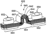
도 13은 예시적인 일 실시예에 따라 형성된 전력 단자 커넥터(602)의 측면 사시도이다. 전력 단자 커넥터(602)는 버스 바 조립체(640)를 포함한다. 버스 바 조립체(640)는 제1 다층 버스 바(642), 제2 다층 버스 바(644), 및 제3 다층 버스 바(646)를 포함한다. 버스 바 조립체(640)는 3-적층 버스 바 조립체를 형성한다. 선택 사항으로, 다층 버스 바들(642, 644, 646)은 서로 실질적으로 마찬가지일 수 있다. 다수의 다층 버스 바들(642, 644, 646)을 버스 바 조립체(640) 내에 제공함으로써, 버스 바 조립체(640)가, 더욱 적은 개수의 층들을 갖는 버스 바 조립체보다 높은 전류를 도통할 수 있다.13 is a side perspective view of a
전력 단자 커넥터(602)는 버스 바 조립체(640)에 결합된 제1 단자 조립체(652) 및 버스 바 조립체(640)에 결합된 제2 단자 조립체(654)를 포함한다. 제1 및 제2 단자 조립체들(652, 654)은 (도 11에 도시한) 제1 및 제2 단자 조립체들(452, 455)과 실질적으로 마찬가지일 수 있다. 제1 단자 조립체(652)는 (도 2에 도시한) 제1 핀(124)에 결합되도록 구성된다. 제2 단자 조립체(654)는 (도 2에 도시한) 제2 핀(126)에 결합되도록 구성된다. 다층 버스 바들(642, 644, 646)은, 유연하며, 서로 다양한 거리에 있을 수 있는 핀들(124, 126)에 장착하도록 제1 단자 조립체(652)와 제2 단자 조립체(654) 간의 상대 위치를 변경하기 위해 및/또는 핀들(124, 126)에 대한 접속 후 진동을 수용하기 위해 버스 바 조립체(640)를 길어지게 하거나 짧아지게 할 수 있다.The
다층 버스 바들(642, 644, 646)의 각각은 다층 버스 바(150)와 실질적으로 마찬가지일 수 있다. 다층 버스 바들(642, 644, 646)의 각각은, 제1 장착부(660), 제2 장착부(662), 및 제1 및 제2 장착부들(660, 662) 간의 유연부(664)를 포함한다. 예시적인 일 실시예에서, 제1 장착부(660), 제2 장착부(662), 및/또는 유연부(664)는 적층 구성으로 금속 시트들의 다수의 층들을 갖는다. 유연부(664)는, 형상을 변경하여 제1 및 제2 장착부들(660, 662)의 상대 위치를 변경하도록 구성된다. 다층 버스 바들(642, 644, 646)은 도전성을 갖는다. 예시적인 일 실시예에서, 다층 버스 바들(642, 644, 646)은 구리로 제조되지만, 대체 실시예들에서는 다른 재료를 사용할 수도 있다. 구리 시트는, 제1 장착부(660), 제2 장착부(662), 및 유연부(664)를 잇는 적층 구성으로 구리 시트들의 다수의 층들을 형성하도록 여러 번 접힌다. 임의의 개수의 접힘부, 및 이에 따른 임의의 개수의 시트들을 제공할 수 있다. 3-적층 버스 바 조립체(640) 내에 다수의 다층 버스 바들(642, 644, 646)을 제공함으로써, 3-적층 버스 바 조립체(640)가, 2-적층 버스 바 조립체 또는 단일 다층 버스 바 조립체보다 높은 전류를 도통할 수 있다.Each of the multi-layer bus bars 642, 644, 646 may be substantially similar to the
선택 사항으로, 다층 버스 바들(642, 644, 646)의 유연부들(664) 간에 갭들(667, 668)을 제공한다. 갭들(667, 668)은, 유연부들(664)이 서로 휘어지거나 이동할 수 있게 하는 등 다층 버스 바들(642, 644. 646) 간의 상대 이동을 가능하게 한다.Optionally,
Claims (11)
제1 장착부(160), 제2 장착부(162), 및 상기 제1 장착부와 상기 제2 장착부 간의 유연부(164)를 갖는 다층 버스 바(multi-layered buss bar; 150)와,
상기 제1 장착부(160)에 결합된 제1 단자 조립체(152) 및 상기 제2 장착부(162)에 결합된 제2 단자 조립체(154)를 포함하고,
상기 유연부는 금속 시트들의 다수의 층들을 적층 구성으로 갖고,
상기 제1 및 제2 단자 조립체들은 대응하는 전력 단자들(104, 105)의 대응하는 핀들(124, 126)에 결합되도록 구성되고,
상기 다층 버스 바(150)는 상기 제1 및 제2 단자 조립체들(152, 154)에 결합된 상기 전력 단자들(104, 105)을 전기적으로 상호 접속하도록 구성된, 전력 단자 커넥터(102).As the power terminal connector 102,
A multi-layered buss bar 150 having a first mounting portion 160, a second mounting portion 162, and a flexible portion 164 between the first mounting portion and the second mounting portion,
A first terminal assembly 152 coupled to the first mounting portion 160 and a second terminal assembly 154 coupled to the second mounting portion 162,
Said flexible portion having a plurality of layers of metal sheets in a laminated configuration,
The first and second terminal assemblies are configured to couple to corresponding pins (124, 126) of corresponding power terminals (104, 105)
The multi-layer bus bar (150) is configured to electrically interconnect the power terminals (104, 105) coupled to the first and second terminal assemblies (152, 154).
상기 제1 및 제2 단자 조립체들의 각각은,
상기 대응하는 장착부로부터 개별적으로 제공되고 상기 대응하는 장착부에 결합되고, 대응하는 전력 단자의 핀(124)을 수용하고 상기 핀에 전기적으로 접속되도록 구성된 소켓(210)을 구비하는, 단자 본체(200)와,
상기 단자 본체에 결합되고, 잠금 위치와 이격(clearance) 위치 간에 이동가능하고, 상기 대응하는 단자 조립체를 상기 핀에 고정하기 위해 상기 잠금 위치에서 상기 핀과 체결하도록 구성되고, 상기 이격 위치에서 상기 핀으로부터 체결 해제되도록 구성된 스프링 클립(206)과,
상기 단자 본체에 대하여 이동가능하고, 상기 캡이 기동함에 따라 상기 스프링 클립을 상기 잠금 위치와 상기 이격 위치 간에 이동시키도록 상기 스프링 클립에 결합된 캡(208)을 포함하고,
상기 다층 버스 바는 내부에 수용되는 복수의 상기 핀을 전기적으로 상호 접속하도록 상기 제1 및 제2 단자 조립체들의 단자 본체들을 전기적으로 결합하는, 전력 단자 커넥터(102).The connector assembly of claim 1, further comprising a first terminal assembly (152) coupled to the corresponding mounting portion (160) and a second terminal assembly (154) coupled to the second mounting portion (162)
Wherein each of the first and second terminal assemblies includes:
And a socket (210) that is separately provided from the corresponding mounting portion and is coupled to the corresponding mounting portion and configured to receive a pin (124) of a corresponding power terminal and to be electrically connected to the pin, Wow,
A pin assembly coupled to the terminal body and configured to be movable between a locked position and a clearance position and to engage the pin at the locked position to secure the corresponding terminal assembly to the pin, A spring clip 206 configured to be disengaged from the spring clip 206,
And a cap (208) movable relative to the terminal body and coupled to the spring clip to move the spring clip between the locked position and the spaced position as the cap is activated,
Wherein the multi-layer bus bar electrically couples the terminal bodies of the first and second terminal assemblies to electrically interconnect a plurality of the pins received therein.
핀(124)을 갖는 제1 전력 단자(104)를 구비하는 제1 헤더(120)와,
핀(126)을 갖는 제2 전력 단자(105)를 구비하는 제2 헤더(122)와,
상기 제1 및 제2 전력 단자들(104, 105)에 결합되고 상기 제1 및 제2 전력 단자들을 전기적으로 상호 접속하는 전력 단자 커넥터(102)를 포함하고,
상기 전력 단자 커넥터(102)는,
제1 장착부(160), 제2 장착부(162), 및 상기 제1 장착부(160)와 상기 제2 장착부(162) 간의 유연부(164)를 갖는 다층 버스 바(150)와,
상기 제1 장착부(160)에 결합된 제1 단자 조립체(152) 및 상기 제2 장착부(162)에 결합된 제2 단자 조립체(154)를 포함하고,
상기 유연부(164)는 금속 시트들의 다수의 층들을 적층 구성으로 갖고,
상기 제1 및 제2 단자 조립체들(152, 154)은 상기 제1 및 제2 핀들(124, 126)에 각각 결합되고,
상기 다층 버스 바(150)는 내부에 수용되는 상기 핀들을 전기적으로 상호 접속하도록 상기 제1 및 제2 단자 조립체들(104, 105)을 전기적으로 결합하는, 커넥터 시스템.A connector system comprising:
A first header 120 having a first power terminal 104 having a pin 124,
A second header 122 having a second power terminal 105 having a pin 126,
And a power terminal connector (102) coupled to the first and second power terminals (104, 105) and electrically interconnecting the first and second power terminals,
The power terminal connector (102)
A multilayer bus bar 150 having a first mounting portion 160, a second mounting portion 162 and a flexible portion 164 between the first mounting portion 160 and the second mounting portion 162,
A first terminal assembly 152 coupled to the first mounting portion 160 and a second terminal assembly 154 coupled to the second mounting portion 162,
The flexible portion 164 has a plurality of layers of metal sheets in a stacked configuration,
The first and second terminal assemblies 152 and 154 are coupled to the first and second pins 124 and 126, respectively,
The multi-layer bus bar (150) electrically couples the first and second terminal assemblies (104, 105) to electrically interconnect the pins received therein.
Applications Claiming Priority (3)
| Application Number | Priority Date | Filing Date | Title |
|---|---|---|---|
| US13/267,638 US8721368B2 (en) | 2011-10-06 | 2011-10-06 | Power terminal connector and system |
| US13/267,638 | 2011-10-06 | ||
| PCT/US2012/058510 WO2013052519A2 (en) | 2011-10-06 | 2012-10-03 | Power terminal connector and system |
Publications (1)
| Publication Number | Publication Date |
|---|---|
| KR20140053400A true KR20140053400A (en) | 2014-05-07 |
Family
ID=47146663
Family Applications (1)
| Application Number | Title | Priority Date | Filing Date |
|---|---|---|---|
| KR1020147008540A KR20140053400A (en) | 2011-10-06 | 2012-10-03 | Power terminal connector and system |
Country Status (6)
| Country | Link |
|---|---|
| US (1) | US8721368B2 (en) |
| JP (1) | JP6025223B2 (en) |
| KR (1) | KR20140053400A (en) |
| CN (1) | CN103875094B (en) |
| DE (1) | DE112012004155T5 (en) |
| WO (1) | WO2013052519A2 (en) |
Cited By (2)
| Publication number | Priority date | Publication date | Assignee | Title |
|---|---|---|---|---|
| WO2017209428A1 (en) * | 2016-05-30 | 2017-12-07 | 삼성에스디아이주식회사 | Battery module |
| KR20220061820A (en) * | 2020-11-06 | 2022-05-13 | 강민정 | Single-plate flexible busbar and manufacturing method thereof |
Families Citing this family (33)
| Publication number | Priority date | Publication date | Assignee | Title |
|---|---|---|---|---|
| DE102011076624A1 (en) * | 2011-05-27 | 2012-11-29 | Elringklinger Ag | cell connectors |
| US9337466B2 (en) | 2012-12-07 | 2016-05-10 | Tyco Electronics Corporation | Power terminal connector |
| DE102013208230A1 (en) * | 2013-05-06 | 2014-11-06 | Robert Bosch Gmbh | Cell connector and method of making a cell connector |
| DE102013217815A1 (en) * | 2013-09-06 | 2015-03-12 | Robert Bosch Gmbh | A flexible cell connector and method of making a flexible cell connector for electrically connecting cells of an energy storage device |
| KR101688488B1 (en) * | 2013-09-17 | 2016-12-21 | 삼성에스디아이 주식회사 | Battery module |
| KR102215911B1 (en) * | 2013-09-25 | 2021-02-17 | 티이 커넥티비티 코포레이션 | Power terminal connector |
| CN103824991B (en) * | 2014-03-13 | 2016-08-17 | 苏州易美新思新能源科技有限公司 | A kind of superposing type flexible connection structure for battery bag |
| US9281673B2 (en) * | 2014-04-03 | 2016-03-08 | Ford Global Technologies, Llc | Deformable busbar assembly and bus bar installation method |
| US10396405B2 (en) * | 2014-11-10 | 2019-08-27 | Te Connectivity Corporation | Bus bar for a battery connector system |
| DE102014017622A1 (en) | 2014-11-27 | 2016-06-02 | Audi Ag | Connecting element, current collecting device and associated manufacturing method |
| JP2016119188A (en) * | 2014-12-19 | 2016-06-30 | 株式会社オートネットワーク技術研究所 | Flexible connection terminal and power storage module |
| DE102016200961A1 (en) * | 2016-01-25 | 2017-07-27 | Bayerische Motoren Werke Aktiengesellschaft | Connector system, battery module, method of forming a tap and operating device |
| CN107134674B (en) * | 2016-02-29 | 2021-04-27 | 泰科电子(上海)有限公司 | Conductive connecting piece and connecting assembly |
| JP6349345B2 (en) * | 2016-05-20 | 2018-06-27 | 矢崎総業株式会社 | Plug connector and power circuit breaker |
| US10062977B2 (en) * | 2016-10-14 | 2018-08-28 | Inevit Llc | Module-to-module power connector between battery modules of an energy storage system and arrangement thereof |
| JP6741215B2 (en) * | 2017-01-20 | 2020-08-19 | 株式会社オートネットワーク技術研究所 | Connection module |
| JP6856391B2 (en) * | 2017-01-31 | 2021-04-07 | 矢崎総業株式会社 | Bus bar |
| EP3804947A1 (en) * | 2017-04-04 | 2021-04-14 | Dae San Electronics Co., Ltd. | Bus bar manufacturing method and bus bar manufactured thereby |
| US10285301B1 (en) * | 2018-04-23 | 2019-05-07 | Dell Products, L.P. | Multi-axis alignment enclosure system for wall-mounted power delivery system |
| DE102018111734B3 (en) | 2018-05-16 | 2019-06-06 | Harting Electric Gmbh & Co. Kg | High-current connectors and method for its assembly |
| WO2020002963A1 (en) * | 2018-06-28 | 2020-01-02 | 日産自動車株式会社 | Electric device |
| CN110867693B (en) * | 2018-08-28 | 2021-03-30 | 光宝电子(广州)有限公司 | Jumper and power distribution device |
| US10879658B2 (en) | 2018-08-31 | 2020-12-29 | Hamilton Sundstrand Corporation | Load connectors for power panel assemblies |
| FR3094578B1 (en) * | 2019-04-01 | 2021-12-10 | Aptiv Tech Ltd | Power connection device for electric heater and connection assembly comprising this device. |
| DE102019112372A1 (en) * | 2019-05-13 | 2020-11-19 | Bayerische Motoren Werke Aktiengesellschaft | High-voltage battery for a motor vehicle with module connectors and motor vehicle |
| JP2021026946A (en) * | 2019-08-07 | 2021-02-22 | 矢崎総業株式会社 | Manufacturing method for laminated bus bar, manufacturing apparatus for laminated bus bar, and laminated bus bar |
| CN114245953A (en) * | 2019-08-27 | 2022-03-25 | 株式会社自动网络技术研究所 | Flexible bus bar, composite bus bar, electricity storage pack, and method for manufacturing flexible bus bar |
| EP4075577B1 (en) * | 2019-12-12 | 2024-04-10 | BOE Technology Group Co., Ltd. | Battery compartment, and handle for vehicle |
| DE102020211091A1 (en) | 2020-09-02 | 2022-03-03 | Leoni Bordnetz-Systeme Gmbh | Electrical contact connector and battery |
| US11394158B1 (en) * | 2020-12-29 | 2022-07-19 | Lear Corporation | Electrical connector with adjustable terminals |
| EP4068490A4 (en) * | 2021-01-29 | 2023-05-03 | Contemporary Amperex Technology Co., Limited | Battery cell, battery, electric device, and manufacturing method and device for battery cell |
| US11710935B2 (en) * | 2021-06-11 | 2023-07-25 | Te Connectivity Solutions Gmbh | Power connector system |
| JP7389770B2 (en) * | 2021-06-15 | 2023-11-30 | 矢崎総業株式会社 | Conductor for busbar wires and busbar wires |
Family Cites Families (17)
| Publication number | Priority date | Publication date | Assignee | Title |
|---|---|---|---|---|
| US3208030A (en) * | 1962-12-06 | 1965-09-21 | Ibm | Electrical connector |
| US4042759A (en) | 1975-08-25 | 1977-08-16 | Alexander Cella | Battery quick disconnect system |
| DE8426772U1 (en) | 1984-09-11 | 1984-11-29 | Accumulatorenwerke Hoppecke Carl Zoellner & Sohn GmbH & Co KG, 5790 Brilon | ACCUMULATOR WITH CELL CONNECTORS |
| US4830624A (en) | 1988-02-09 | 1989-05-16 | Rose Keith A | Twist-on battery connector |
| JPH06140020A (en) | 1992-10-22 | 1994-05-20 | Yazaki Corp | Battery connection terminal |
| JP2952550B2 (en) * | 1993-09-13 | 1999-09-27 | 矢崎総業株式会社 | Protective cover for battery post connection terminal |
| JP3579130B2 (en) * | 1995-06-21 | 2004-10-20 | タイコエレクトロニクスアンプ株式会社 | Electrical connector |
| JP3206865B2 (en) * | 1995-07-03 | 2001-09-10 | 矢崎総業株式会社 | Battery electrode connection structure and fittings |
| JP3211935B2 (en) | 1995-07-19 | 2001-09-25 | 矢崎総業株式会社 | Electrode post connection terminal of battery and method of manufacturing electrode post connection terminal |
| JP3373108B2 (en) * | 1996-03-28 | 2003-02-04 | 矢崎総業株式会社 | Electrical connection structure between battery terminals |
| US5886501A (en) | 1997-04-07 | 1999-03-23 | General Motors Corporation | Battery pack electrical interconnects |
| FR2808117B1 (en) * | 2000-03-31 | 2003-01-24 | Schneider Electric Ind Sa | ELECTRICAL SWITCHING APPARATUS COMPRISING A VACUUM BULB AND A FLEXIBLE ELECTRICAL CONNECTION |
| DE10352761B4 (en) * | 2003-11-12 | 2006-06-08 | Wolf Neumann-Henneberg | Connection contact for electrical contacting of a printed circuit board or a punched grid |
| US7294020B2 (en) | 2005-05-25 | 2007-11-13 | Alcoa Fujikura Ltd. | Canted coil spring power terminal and sequence connection system |
| US7229327B2 (en) | 2005-05-25 | 2007-06-12 | Alcoa Fujikura Limited | Canted coil spring power terminal and sequence connection system |
| US7614921B2 (en) | 2007-05-04 | 2009-11-10 | Group Dekko, Inc. | Battery post electrical terminal for electrically coupling an electrical conductor with the battery post of a battery |
| DE102011080977A1 (en) | 2011-08-16 | 2013-02-21 | Sb Limotive Company Ltd. | Cell connector, battery cell module, battery, method for producing a cell connector and motor vehicle |
-
2011
- 2011-10-06 US US13/267,638 patent/US8721368B2/en active Active
-
2012
- 2012-10-03 KR KR1020147008540A patent/KR20140053400A/en not_active Application Discontinuation
- 2012-10-03 DE DE112012004155.0T patent/DE112012004155T5/en not_active Withdrawn
- 2012-10-03 WO PCT/US2012/058510 patent/WO2013052519A2/en active Application Filing
- 2012-10-03 JP JP2014534646A patent/JP6025223B2/en not_active Expired - Fee Related
- 2012-10-03 CN CN201280048751.XA patent/CN103875094B/en active Active
Cited By (3)
| Publication number | Priority date | Publication date | Assignee | Title |
|---|---|---|---|---|
| WO2017209428A1 (en) * | 2016-05-30 | 2017-12-07 | 삼성에스디아이주식회사 | Battery module |
| US11515605B2 (en) | 2016-05-30 | 2022-11-29 | Samsung Sdi Co., Ltd. | Battery module |
| KR20220061820A (en) * | 2020-11-06 | 2022-05-13 | 강민정 | Single-plate flexible busbar and manufacturing method thereof |
Also Published As
| Publication number | Publication date |
|---|---|
| WO2013052519A3 (en) | 2013-08-15 |
| JP2014532269A (en) | 2014-12-04 |
| JP6025223B2 (en) | 2016-11-16 |
| US8721368B2 (en) | 2014-05-13 |
| CN103875094B (en) | 2017-02-01 |
| WO2013052519A2 (en) | 2013-04-11 |
| US20130089996A1 (en) | 2013-04-11 |
| DE112012004155T5 (en) | 2014-07-10 |
| CN103875094A (en) | 2014-06-18 |
Similar Documents
| Publication | Publication Date | Title |
|---|---|---|
| KR20140053400A (en) | Power terminal connector and system | |
| EP2929596B1 (en) | Power terminal connector | |
| KR101556484B1 (en) | Power terminal connector and system | |
| CN102299288B (en) | Battery | |
| US9337466B2 (en) | Power terminal connector | |
| US20180076585A1 (en) | Electrical and mechanical connector | |
| US10116078B1 (en) | High current compression blade connection system | |
| US9837687B2 (en) | Battery module | |
| US20210194193A1 (en) | Electrical Connector, Connector Assembly And Charging Robot For A Conductive Charging System | |
| CN110581398B (en) | Power terminal connector | |
| US20170179786A1 (en) | Electrical connection structure, terminal structure, and vehicle | |
| US9972815B2 (en) | Traction battery spacer with retention element | |
| US20220209450A1 (en) | Electrical Connection Device For Vehicle | |
| KR102472233B1 (en) | Battery module | |
| KR102215911B1 (en) | Power terminal connector | |
| KR102098404B1 (en) | High voltage connector for vehicle | |
| EP3572268B1 (en) | Manual service disconnect for battery system | |
| CN100514750C (en) | Self-locking wire terminal module and method of manufacturing the same and wire termination system | |
| CN103181032A (en) | High-current plug connector | |
| EP3565065A1 (en) | Multipath electric power connection assembly | |
| US20230208066A1 (en) | Multiple row electrical connector assembly having a terminal-less connection system | |
| JP6499142B2 (en) | Connection device | |
| CN114388965A (en) | Battery module support beam | |
| CN117916942A (en) | Bus bar assembly for battery cell array | |
| CN112490725A (en) | Conductive module, plug connector, charging connector and charging mechanism |
Legal Events
| Date | Code | Title | Description |
|---|---|---|---|
| A201 | Request for examination | ||
| E902 | Notification of reason for refusal | ||
| E601 | Decision to refuse application |