KR20140052975A - Winding switching circuit and thermal protection for dual voltage hermetic induction motor of hermetic cooling compressor - Google Patents
Winding switching circuit and thermal protection for dual voltage hermetic induction motor of hermetic cooling compressor Download PDFInfo
- Publication number
- KR20140052975A KR20140052975A KR1020137024002A KR20137024002A KR20140052975A KR 20140052975 A KR20140052975 A KR 20140052975A KR 1020137024002 A KR1020137024002 A KR 1020137024002A KR 20137024002 A KR20137024002 A KR 20137024002A KR 20140052975 A KR20140052975 A KR 20140052975A
- Authority
- KR
- South Korea
- Prior art keywords
- node
- switch
- winding
- main winding
- circuit
- Prior art date
Links
Images


Classifications
-
- H—ELECTRICITY
- H02—GENERATION; CONVERSION OR DISTRIBUTION OF ELECTRIC POWER
- H02P—CONTROL OR REGULATION OF ELECTRIC MOTORS, ELECTRIC GENERATORS OR DYNAMO-ELECTRIC CONVERTERS; CONTROLLING TRANSFORMERS, REACTORS OR CHOKE COILS
- H02P1/00—Arrangements for starting electric motors or dynamo-electric converters
- H02P1/16—Arrangements for starting electric motors or dynamo-electric converters for starting dynamo-electric motors or dynamo-electric converters
- H02P1/42—Arrangements for starting electric motors or dynamo-electric converters for starting dynamo-electric motors or dynamo-electric converters for starting an individual single-phase induction motor
-
- H—ELECTRICITY
- H02—GENERATION; CONVERSION OR DISTRIBUTION OF ELECTRIC POWER
- H02H—EMERGENCY PROTECTIVE CIRCUIT ARRANGEMENTS
- H02H5/00—Emergency protective circuit arrangements for automatic disconnection directly responsive to an undesired change from normal non-electric working conditions with or without subsequent reconnection
- H02H5/04—Emergency protective circuit arrangements for automatic disconnection directly responsive to an undesired change from normal non-electric working conditions with or without subsequent reconnection responsive to abnormal temperature
-
- H—ELECTRICITY
- H02—GENERATION; CONVERSION OR DISTRIBUTION OF ELECTRIC POWER
- H02H—EMERGENCY PROTECTIVE CIRCUIT ARRANGEMENTS
- H02H7/00—Emergency protective circuit arrangements specially adapted for specific types of electric machines or apparatus or for sectionalised protection of cable or line systems, and effecting automatic switching in the event of an undesired change from normal working conditions
- H02H7/08—Emergency protective circuit arrangements specially adapted for specific types of electric machines or apparatus or for sectionalised protection of cable or line systems, and effecting automatic switching in the event of an undesired change from normal working conditions for dynamo-electric motors
-
- H—ELECTRICITY
- H02—GENERATION; CONVERSION OR DISTRIBUTION OF ELECTRIC POWER
- H02K—DYNAMO-ELECTRIC MACHINES
- H02K11/00—Structural association of dynamo-electric machines with electric components or with devices for shielding, monitoring or protection
-
- H—ELECTRICITY
- H02—GENERATION; CONVERSION OR DISTRIBUTION OF ELECTRIC POWER
- H02K—DYNAMO-ELECTRIC MACHINES
- H02K11/00—Structural association of dynamo-electric machines with electric components or with devices for shielding, monitoring or protection
- H02K11/20—Structural association of dynamo-electric machines with electric components or with devices for shielding, monitoring or protection for measuring, monitoring, testing, protecting or switching
- H02K11/25—Devices for sensing temperature, or actuated thereby
-
- H—ELECTRICITY
- H02—GENERATION; CONVERSION OR DISTRIBUTION OF ELECTRIC POWER
- H02K—DYNAMO-ELECTRIC MACHINES
- H02K17/00—Asynchronous induction motors; Asynchronous induction generators
- H02K17/02—Asynchronous induction motors
- H02K17/04—Asynchronous induction motors for single phase current
- H02K17/06—Asynchronous induction motors for single phase current having windings arranged for permitting pole-changing
-
- H—ELECTRICITY
- H02—GENERATION; CONVERSION OR DISTRIBUTION OF ELECTRIC POWER
- H02K—DYNAMO-ELECTRIC MACHINES
- H02K3/00—Details of windings
- H02K3/04—Windings characterised by the conductor shape, form or construction, e.g. with bar conductors
- H02K3/28—Layout of windings or of connections between windings
-
- H—ELECTRICITY
- H02—GENERATION; CONVERSION OR DISTRIBUTION OF ELECTRIC POWER
- H02P—CONTROL OR REGULATION OF ELECTRIC MOTORS, ELECTRIC GENERATORS OR DYNAMO-ELECTRIC CONVERTERS; CONTROLLING TRANSFORMERS, REACTORS OR CHOKE COILS
- H02P4/00—Arrangements specially adapted for regulating or controlling the speed or torque of electric motors that can be connected to two or more different electric power supplies
Landscapes
- Engineering & Computer Science (AREA)
- Power Engineering (AREA)
- Microelectronics & Electronic Packaging (AREA)
- Control Of Ac Motors In General (AREA)
Abstract
본 발명은 밀폐형 냉각 압축기에 사용되는 이중 전압 밀폐형 유도 모터에 대한 열 보호 및 권선 스위칭 회로에 관한 것이며, 회로는 주권선(M1 및 M2)의 두 코일, 보조 권선(A), 출력 배열(115V 또는 220V)의 각각에 대하여 원하는 연결을 바탕으로 연결되기도 하고 연결되지 않기도 하는 3 개 스위치(R1, R2 및 R3), 스타트업 릴레이(R) 및 과열로 부터 두 개의 주권선(M1, M2)을 보호하는 열 보호 수단으로 구성되며, 회로는 제1 및 제2 배열에서 동작하고, 제1 배열에서, 제1 스위치(R1)과 제3 스위치(R3)가 연결되고, 제2 스위치(R2)는 연결되지 않으며, 제1 주권선(M1), 제2 주권선(M2) 및 보조권선(A)은 병렬로 연결되고, 제2 배열에서, 제1 스위치(R1)와 제3 스위치(R3)는 연결되지 않고, 제2 스위치(R2)는 연결되며, 제1 주권선(M1)과 제2 주권선(M2)은 직렬로 연결되고, 보조 권선(A)은 오직 제2 주권선(M2)에 병렬로 연결된다. The present invention relates to a thermal protection and winding switching circuit for a dual voltage enclosed induction motor used in a hermetic refrigeration compressor, the circuit comprising two coils of the main winding lines M1 and M2, a secondary winding A, (R1, R2 and R3), the start-up relay (R) and the two main lines M1 and M2 from overheating, both of which may or may not be connected based on the desired connection, The first switch R1 and the third switch R3 are connected and the second switch R2 is connected in the first and second arrangements, The first main winding M1 and the second main winding M2 are connected in parallel and in the second arrangement the first switch R1 and the third switch R3 are connected The second switch R2 is connected and the first main winding line M1 and the second main winding line M2 are connected in series and the auxiliary winding A is connected in series, And is connected in parallel to the second main winding line M2 only.
Description
본 발명은 약 90V와 260V 전체 전압범위에서 동작하는 모터를 허용하는 밀폐형 냉각 압축기에 일반적으로 사용하는 단상 이중 전압 유도 모터에 대한 열적 보호와 권선(winding) 스위칭회로에 관한 것이다.The present invention relates to a thermal protection and winding switching circuit for a single phase dual voltage induction motor commonly used in hermetic refrigeration compressors that allows motors operating at about 90V and 260V full voltage range.
냉각을 위한 밀폐형 압축기에 사용되는 단상 유도모터는 일반적으로 제한된 전압 범위에서 사용되도록 설계되어 있다. 일반적으로, 디자인은 모터에 적용할 전압보다 10% 작은 전압(subvoltage)에서 부터 10% 많은 전압(overvoltage)까지 적용할 수 있다. 이것은 115V용으로 설계된 모터는 103V에서 127V의 범위가 이에 적용되었을 때 문제없이 작동함을 의미한다. 10%를 초과하는 전압의 변화에 대하여는, 동일한 프로젝트를 사용할 수 없으나, 이 전압에는 새로운 권선 배열을 사용해야한다. Single-phase induction motors used in hermetic compressors for cooling are generally designed for use in a limited voltage range. Generally, the design can be applied from 10% less voltage to 10% overvoltage. This means that motors designed for 115V will operate without problems when the range of 103V to 127V is applied. For changes in voltage exceeding 10%, the same project can not be used, but a new winding arrangement should be used for this voltage.
넓은 범위의 전압에 대해 동일한 권선 회로 프로젝트의 사용을 방해하는 또 다른 요인은 제한된 전압 변화 범위 내에서 기능을 하도록 사이징되고 이 범위를 벗어난 전압이 전송되면 기능을 잃어버리는 콘덴서, 릴레이, 열 보호기 등과 같은 다른 전기 부품의 사양 때문이다.Another factor that hinders the use of the same winding circuit project for a wide range of voltages is the ability to operate within a limited voltage range, such as capacitors, relays, thermal protectors, It is due to the specifications of other electrical components.
대부분의 에너지 영업권 보유자는 115-127V(미국, 브라질 등) 또는 220-240V(유럽, 중국 등)의 저전압을 공급한다. 이 차이는 전기 모터가 각각의 전압에 맞게 맞춤형이 될 것을 요구한다.Most energy goodwill holders supply low voltages between 115-127V (USA, Brazil, etc.) or 220-240V (Europe, China, etc.). This difference requires that the electric motor be tailored to each voltage.
115-127V 또는 220-240V의 전압에서 동작하는 이중 전압 형태의 단상 유도 모터에 대한 일부 배열은 종래 기술에서 이미 알려져 있다.Some arrangements for single phase induction motors in the form of dual voltages operating at voltages of 115-127V or 220-240V are already known in the prior art.
단상 유도 모터는 모터 고정자를 구동하고 출력하는 위상 갭을 가진 순환하는 전류가 통과하는 제1 권선과 제2 권선을 가진다. 듀얼 전압 형태의 유도 모터에는 두 개의 제1 권선(M1 및 M2)과 하나의 제2 권선(A)이 사용된다.The single phase induction motor has a first winding and a second winding through which a circulating current having a phase gap driving and outputting the motor stator is passed. In the induction motor of the dual voltage type, two first windings M1 and M2 and one second winding A are used.
약 115V의 전압이 모터에 적용될 때, 도 1의 A에서와 같이, 두 개의 제1 권선(M1 및 M2)이 병렬로 연결되고, 반면에 출력 전압 220V에서는 도 1B에 도시된 바와 같이, 두 개의 제1 권선(M1과 M2)은 직렬로 연결해야 한다. 이러한 회로 배열은 115V와 220V에 대한 배열로 도 2A 와 2B에 도시된 T-연결 원리를 기반으로 한다. 따라서, 출력 전압에 따라 제1 권선(M1과 M2)의 병렬 연결에 대하여 직렬 연결의 변환(switching)을 제공할 필요가 있다.When a voltage of about 115 V is applied to the motor, two
T-연결은 115V 근처와 약 220V의 전압에 대해 다른 설계를 할 필요없이 전기 모터의 전압 변환의 가능성을 보장하는 간단한 방법이다. 115V와 220V에 대한 주권선과 보조 권선은 둘 다 모두 정확하게 동일하며, 그 때문에 모터 디자인의 표준화가 가능하고, 코드를 생성할 필요성을 제거하여 제조 물류를 촉진한다.The T-connection is a simple way to ensure the possibility of voltage conversion of the electric motor without the need for another design near 115V and a voltage of about 220V. Both the main and auxiliary windings for 115V and 220V are exactly the same, which allows standardization of the motor design and facilitates manufacturing logistics by eliminating the need to generate code.
그러나 밀폐형 압축기 모터에서, 압축기 단자에 접속(access)은 밀폐형 3-핀 단자의 방법으로 일반적으로 제한된다. 이것은 더 많은 핀을 가진 새로운 단자를 사용하지 않으면 권선(M1과 M2)의 단자에 독립적인 접근 가능성이 없기 때문에 T-연결 회로의 응용을 방해한다.However, in hermetic compressor motors, access to the compressor terminals is generally limited by the way of a closed 3-pin terminal. This interferes with the application of the T-junction circuit because there is no independent access to the terminals of the windings (M1 and M2) unless a new terminal with more pins is used.
종래기술에 알려진 T-연결에서, 115V 또는 220V 출력에 대하여 동일한 디자인의 주권선 및 보조 권선을 사용할 수 있는 경우라 할지라도, 회로에 연결되는 다른 전기 부품, 예를 들어 릴레이, 커패시터 및 열 보호기들은 적용되는 전압이 각각 다르다.In a T-connection known in the prior art, other electrical components connected to the circuit, such as relays, capacitors and thermal protectors, may be used, even if the same design of the mains lead and the auxiliary winding are available for a 115 V or 220 V output The voltages applied are different.
각 전압 범위에 대한 구체적인 배열을 요구하는 115V와 220V 전압에 대한 동일한 배열의 전기장치를 사용할 수 있는 냉각을 위한 밀폐형 압축기에 현재까지 사용된 배열 형태는 없으므로, 각각의 전압 범위에 대해 특수한 배열을 요하며, 엔지니어링 코드의 수를 증가시키고, 제조, 유통 및 물류 제어에 부정적인 영향을 준다.There are no arrangements used to date in hermetic compressors for cooling that can use the same arrangement of electrical devices for voltages of 115V and 220V requiring a specific arrangement for each voltage range, so a special arrangement for each voltage range Increases the number of engineering codes, and negatively affects manufacturing, distribution and logistics control.
종래기술의 일부 문헌에는 115V와 220V 장치 사이의 변환(스위칭)을 수행하는 선택적 권선 회로 배열을 보여준다.Some prior art documents show an arrangement of an optional winding circuit that performs the conversion (switching) between 115V and 220V devices.
공개된 특허 문헌 JP 61102189에는 220V와 115V 전압사이를 자동으로 변환(스위칭)하는 모터에 의하여 제어되는 펌프가 개시되어 있다. 모터는 두 전압에 적응하는(adapt) 보조 회로를 가지고 있다. 이 회로는 보조 권선과 두 개의 주권선 조합을 가지고 있다. 출력 전압이 115V 인 경우, 릴레이(relay)가 변환되어, 주권선의 두 개의 조합은 병렬로 연결된다. 출력 전압이 220V 인 경우, 릴레이가 변환되어 두 개의 주권선이 직렬로 연결 배치된다. 모드 115V 및 모드 220V 사이의 변환은 다양한 릴레이의 복잡한 회로에 의해 수행된다. 이 특허 문헌에 표시된 모든 배열에서, 두 개의 주권선의 양극이 서로 직접 연결된다.The disclosed patent JP 61102189 discloses a pump controlled by a motor that automatically switches (switches) between 220V and 115V voltage. The motor has an auxiliary circuit that adapts to both voltages. This circuit has a secondary winding and two main winding combinations. When the output voltage is 115 V, the relay is converted so that the two combinations of the main winding lines are connected in parallel. When the output voltage is 220V, the relay is converted and two main lines are connected in series. The conversion between the mode 115V and the mode 220V is performed by a complex circuit of various relays. In all the arrangements shown in this patent document, the positive poles of the two main lines are directly connected to each other.
특허 문헌 US 5867005는 모터가 115V 또는 220V로 동작하도록 허용하기 위해 적응된(adapted) 모터 회로가 개시되어 있다. 회로는 제1 및 제2 주권선과 커패시터와 직렬로 영구적으로 연결된 보조 권선과 함께 보조 연결을 가진다. 낮은 입력 전압을 가진 제1 배열에서, 제1 주권선과 제2 주권선은 병렬로 연결되고 약 115V의 출력 전압은 제1 주권선에 적용된다. 220V의 입력 전압에 대한 제2 배열에서, 제1 및 제1 주권선은 직렬로 연결되어 있다. 출력 전압은 제1 및 제2 주권선에 적용된다. 이 회로는 이러한 변환을 수행하기 위한 주권선에 연결된 변환기(commutor)로 기능하는 집적회로를 가진다. 이러한 특허 문헌에서 나타난 모든 배열에서, 두 개의 주권선의 양극이 서로 직접 연결된다. 따라서, 이 회로의 배열은 극의 수가 115V와 220V 배열에서 동일하지 않은 단점을 나타낸다.Patent document US 5867005 discloses a motor circuit adapted to allow the motor to operate at 115V or 220V. The circuit has auxiliary connections with auxiliary windings permanently connected in series with the first and second mains lines and the capacitors. In a first arrangement with a low input voltage, the first main winding wire and the second main winding wire are connected in parallel and an output voltage of about 115 V is applied to the first main winding wire. In a second arrangement for an input voltage of 220V, the first and first mains lines are connected in series. The output voltage is applied to the first and second main lines. The circuit has an integrated circuit functioning as a commutator connected to a mains line for performing this conversion. In all the arrangements shown in these patent documents, the poles of the two dominant lines are directly connected to each other. Therefore, the arrangement of this circuit shows the disadvantage that the number of poles is not the same in the 115 V and 220 V arrays.
특허 문헌 GB632468는 단상 이중 전압 모터의 개선을 보여주며, 여기서 주권선은 두 개의 권선으로 나누어 바람직하게는 모터의 극에 감는다. 보조 권선은 주권선과 병렬로 위상 갭을 가지도록 연결되고, 또한 커패시터와 직렬로 연결된다. 220V의 출력 전압의 연결에서, 주권선은 전원 단자에 대하여 직렬로 연결되며, 보조 권선은 주권선에 병렬로 연결되어 있다. 115V의 출력 전압의 연결에서, 주권선은 출력 단자에 대하여 함께 병렬로 연결되며, 보조 권선은 주 단자에 병렬로 연결되어 있다. 두 개의 연결 배열 사이의 변화는 전류 중계(current relay)에 의해 수행된다.Patent document GB 632468 shows an improvement of a single phase dual voltage motor in which the main winding is divided into two windings, preferably wound around the pole of the motor. The auxiliary winding is connected in parallel with the main winding line to have a phase gap and also connected in series with the capacitor. In the connection of the output voltage of 220V, the main winding wire is connected in series with the power supply terminal, and the auxiliary winding is connected in parallel with the main winding wire. In the connection of the output voltage of 115V, the main winding wire is connected in parallel to the output terminal, and the auxiliary winding is connected in parallel to the main terminal. The change between the two connected arrays is performed by a current relay.
이러한 종래 기술에서 설명하는 모든 회로는 T 연결을 기반으로 하고 115V와 220V의 출력 전압에 적응하기(adapt) 위하여 권선, 릴레이 및 콘덴서사이에 다른 연결 배열을 사용하고 있다.All of the circuits described in this prior art are based on T-connections and use different connection arrangements between windings, relays, and capacitors to adapt to the output voltages of 115V and 220V.
그러나, 종래기술의 모터는 밀폐된 모터는 없고 그래서 밀폐된 단자를 사용할 필요가 없으며, 본 발명에 따른 밀폐 모터의 경우에 존재하는 핀에 대한 접근의 제한을 제공하지 않는다. 또한, 주 코일의 각 분지(branch)에 대한 독립적인 핀을 가진 밀폐된 단자의 사용은 주권선의 두 분지(branch)에 대해 별도로 수행해야하는 과열에 대한 보호가 필요하다. 종래기술의 이들 회로는 두 배열(115V 및 220V)에서 작동하는 각 권선에 대해 자신의 열 보호기를 사용하는 유도 모터에 대한 권선 회로 연결 배열을 제안하지 않았으며, 따라서 그들은 과열로 인해 손상되기 쉽다. 종래 문헌에서의 모터는 밀폐형이 아니고, 보호는 전원에 직렬로 연결할 수 있으며, 따라서, 그들은 모터의 권선 회로의 다른 구성 부품 사이에 연결된 두 개의 보호기를 필요로 하지 않을 수 있다. 권선 회로에 열 보호기의 결합은 궁극적으로 그 복잡성을 증가시키고 115V 와 220V 배열사이의 변환을 방해한다.However, prior art motors do not have a hermetic motor, so there is no need to use a closed terminal and does not provide a limitation of access to the pin present in the case of the sealing motor according to the invention. In addition, the use of a closed terminal with independent pins for each branch of the main coil requires protection against overheating, which must be performed separately for the two branches of the mains lead. These circuits of the prior art do not propose a winding circuit connection arrangement for an induction motor that uses its own thermal protector for each winding operating in two arrangements (115 V and 220 V) and are therefore prone to damage due to overheating. The motors in the prior art are not hermetic and the protection may be connected in series with the power supply and therefore they may not require two protectors connected between the other components of the winding circuit of the motor. The combination of a thermal protector in the winding circuit ultimately increases its complexity and hinders the conversion between the 115V and 220V arrays.
본 발명의 목적은 밀폐형 압축기에 사용하기 적합하고, 동일한 전기 부품을 사용함으로써 115V 배열에서 220V 배열로 변환하기 쉬운, 두 개의 주 코일에 대한 독립된 열 보호기능을 가진 이중 전압 유도 모터를 위한 권선 스위칭 회로 및 열 보호기능(thermal protection)을 제공하는 것이다. It is an object of the present invention to provide a winding switching circuit for a dual voltage induction motor suitable for use in a hermetic compressor and having independent thermal protection for two main coils which is easy to convert from a 115 V arrangement to a 220 V arrangement, And thermal protection.
또한 본 발명의 목적은 90V 내지 260V 사이 전체 범위에서 작동할 수 있는 유도 모터를 허용하는 이중 전압 유도 모터에 대한 권선 스위칭 회로 및 열 보호기능을 제공하는 것이다.It is also an object of the present invention to provide a winding switching circuit and a thermal protection function for a dual voltage induction motor that allows an induction motor capable of operating in a full range between 90V and 260V.
본 발명 과제의 해결 수단은 제1 주권선(M1)은 음극은 제1 노드(N1)와 연결되고, 양극은 제2 노드(N2)에 연결되며, 제2 주권선(M2)은 양극은 제2 노드(N3)와 연결되고, 음극은 제4 노드(N4)에 연결되고, 제1 스위치(R1)는 제2 노드(N2)와 제3 노드(N3)사이에 연결되고, 스타트업 릴레이(R)는 제3 노드(N3)에 연결되며, 보조 권선(A)은 양극이 스타트업 릴레이(R)에 연결되며, 음극은 제4 노드(N4)에 연결되고, 보조 권선(A)은 제2 주권선과 병렬로 연결되고, 제2 스위치(R2)는 제3 노드(N3)와 제1 노드(N1)사이에 연결되며, 제3 스위치(R3)는 제1 노드(N1)와 제5 노드(N5)사이에 연결되며, 전압 소스는 제2 노드(N2)와 제5 노드(5)사이에 연결되고, 회로는 제1 및 제2 배열에서 작동하고, 제1 배열에서, 제1 스위치(R1)와 제 3 스위치(R3)가 연결되며, 제2 스위치가 연결되지 않고, 제1 주권선(M1), 제2 주권선(M2) 및 보조 권선(A)은 병렬로 연결되며, 제2 배열에서, 제1 스위치(R1)와 제3 스위치(R3)는 연결되지 않으며, 제2 스위치(R2)는 연결되고, 제1 주권선(M1)과 제2 주권선(M2)이 직렬로 연결되며, 보조권선(A)은 단지 제2 주권선(M2)과 병렬로 연결되고, 회로는 제1 및 제2 배열에서 제1 및 제2 주권선(M1, M2)의 열적 보호를 수행하는 열적 보호 수단을 포함하는 단상 이중 전압 밀폐형 유도 모터를 위한 열 보호 및 권선 스위칭회로를 제공하는데 있다.The first main winding M1 is connected to the first node N1 and the anode is connected to the second node N2. The second main winding M2 is connected to the anode of the first main winding M1, The first switch R1 is connected between the second node N2 and the third node N3 and the start-up relay N2 is connected between the second node N2 and the third node N3, and the cathode is connected to the fourth node N4, R is connected to the third node N3 and the auxiliary winding A is connected to the start-up relay R and the cathode is connected to the fourth node N4, and the auxiliary winding A is connected to the start- The second switch R2 is connected between the third node N3 and the first node N1 and the third switch R3 is connected between the first node N1 and the fifth node N1 in parallel, (N5), a voltage source is connected between the second node (N2) and the fifth node (5), the circuit operates in the first and second arrangements, and in the first arrangement, the first switch R1 and the third switch R3 are connected and the second switch is not connected and the first main winding line M1, The main winding line M2 and the auxiliary winding A are connected in parallel and in the second arrangement the first switch R1 and the third switch R3 are not connected and the second switch R2 is connected, The first main winding line M1 and the second main winding line M2 are connected in series and the auxiliary winding A is connected in parallel with the second main winding line M2 only and the circuit is arranged in the first and second arrangements The present invention provides a thermal protection and winding switching circuit for a single phase double-voltage hermetic induction motor including thermal protection means for performing thermal protection of the first and second main winding lines M1 and M2.
본 발명은 두 개의 주 코일에 대한 독립된 열 보호기능을 가진 이중 전압 유도 모터를 위한 권선 스위칭 회로 및 열 보호기능(thermal protection)을 제공함으로써 밀폐형 압축기에 사용하기 적합하고, 동일한 전기 부품을 사용함으로써 115V 배열에서 220V 배열로 변환하기 쉬운 유리한 효과가 있다.The present invention is suitable for use in hermetic compressors by providing a winding switching circuit and thermal protection for a dual voltage induction motor with independent thermal protection for the two main coils, There is an advantageous effect that is easy to convert from array to 220V array.
또한 본 발명은 유도 모터를 허용하는 이중 전압 유도 모터에 대한 권선 스위칭 회로 및 열 보호기능을 제공함으로써 90V 내지 260V 사이 전체 범위에서 작동할 수 유리한 효과가 있다.The present invention also has the advantageous effect of operating in the full range between 90V and 260V by providing a winding switching circuit and a thermal protection function for a dual voltage induction motor that allows an induction motor.
본 발명은 도면에 나타난 실행 예를 바탕으로 더 자세히 기술될 것이다.
도 1A와 도 1B - 종래기술에서 사용된 종류의 115V와 220V의 출력 전압 배열에서의 권선 회로의 연결 다이아그램을 나타낸 것이다.
도 2A와 도 2B - 115V와 220V의 출력 전압에 대하여 종래기술에 따른 T-연결 다이아그램을 나타낸 것이다.
도 3A와 도 3B - 115V와 220V의 출력 전압에 대한 배열에서 본 발명의 권선 스위칭 회로 및 열 보호를 위한 연결의 제1 실시 예의 다이아그램이다.
도 4는 유도 모터에서 본 발명의 주권선 회로의 코일 배치의 개략도이다.
도 5는 회로 보호를 위한 열 삼상 보호기를 사용한 115V와 220V의 출력 전압에 대한 본 발명의 권선 스위칭 회로 및 열 보호를 위한 연결의 제2 실시 예의 다이아그램이다.
도 6 및 7은 두 개의 회로 보호 전용의 열보호기를 사용한 115V와 220V의 출력 전압에 대한 본 발명의 권선 스위칭 회로 및 열 보호를 위한 연결의 제3 및 4 실시 예의 다이아그램이다.The present invention will be described in more detail on the basis of examples shown in the drawings.
Figures 1A and 1B show a connection diagram of a winding circuit in an output voltage arrangement of 115V and 220V of the kind used in the prior art.
Figures 2A and 2B show a prior art T-connection diagram for output voltages of 115V and 220V.
3A and 3B - Diagrams of a first embodiment of a winding switching circuit and a connection for thermal protection of the present invention in an arrangement for an output voltage of 115V and 220V.
4 is a schematic view of the coil arrangement of the main winding line circuit of the present invention in an induction motor;
5 is a diagram of a second embodiment of a winding switching circuit and a connection for thermal protection of the present invention for an output voltage of 115 V and 220 V using a thermal three-phase protector for circuit protection.
Figures 6 and 7 are diagrams of third and fourth embodiments of a winding switching circuit and thermal protection connection of the present invention for output voltages of 115 V and 220 V using two circuit protection only thermal protectors.
본 발명을 실시하기 위한 구체적인 내용을 살펴본다.Hereinafter, the present invention will be described in detail.
본 발명의 목적은 밀폐형 냉각 압축기의 단상 이중 전압 밀폐형 유도 모터에 대한 권선 스위칭 회로 및 열 보호에 의해 달성되고, 그 구성은The object of the invention is achieved by a winding switching circuit and thermal protection for a single-phase, double-voltage hermetically-sealed induction motor of a hermetically sealed compressor,
제1 주권선의 음극(negative pole)은 제 1 노드와 연결되고, 양극(positive pole)은 제2 노드에 연결되며, 제2 주권선의 양극은 제3 노드와 연결되고, 음극은 제4 노드에 연결되며, 제1 스위치는 제2 노드와 제3 노드사이에 연결되고, 스타트업 릴레이는 제3 노드에 연결되며, 보조 권선의 양극은 스타트업 릴레이에 연결되며, 음극은 제4 노드에 연결되고, 보조 권선은 제2 주권선과 병렬로 연결되며, 제2 스위치는 제3 노드와 제1 노드사이에 연결되고, 제3 스위치는 제1 노드와 제5 노드사이에 연결되며, 전압 소스는 제2 노드와 제5 노드사이에 연결되도록 구성되어 있다.The negative pole of the first main winding line is connected to the first node, the positive pole is connected to the second node, the positive pole of the second main winding line is connected to the third node, The first switch is connected between the second node and the third node, the start-up relay is connected to the third node, the positive pole of the auxiliary winding is connected to the start-up relay, the cathode is connected to the fourth node, The second switch is connected between the third node and the first node, the third switch is connected between the first node and the fifth node, the voltage source is connected to the second node, And the fifth node.
회로가 제1 및 제2 배열에서 작동할 때, 제1 배열에서는, 제1 스위치와 제 3 스위치가 연결되며, 제2 스위치가 연결되지 않고, 제1 주권선, 제2 주권선 및 보조 권선은 병렬로 연결된다.When the circuit operates in the first and second arrangements, in the first arrangement, the first switch and the third switch are connected, the second switch is not connected, and the first main winding, the second main winding, They are connected in parallel.
제2 배열에서는, 제1 스위치와 제3 스위치는 연결되지 않으며, 제2 스위치는 연결되고, 제1 주권선과 제2 주권선이 직렬로 연결되며, 보조권선은 단지 제2 주권선과 병렬로 연결되고;In the second arrangement, the first switch and the third switch are not connected, the second switch is connected, the first main winding wire and the second main winding wire are connected in series, and the auxiliary winding is connected in parallel with only the second main winding wire ;
회로는 제1 및 제2 배열에서 제1 및 제2 주권선(M1, M2)의 열적 보호를 수행하는 열보호 수단을 포함한다. The circuit includes thermal protection means for performing thermal protection of the first and second main lines M1, M2 in the first and second arrangements.
회로는 90V와 260V 사이의 전압 범위에서 동작하며, 바람직하게는 제1 배열은 115V 가까운 전압 범위에서 동작하며, 제2 배열은 220V 가까운 전압 범위에서 동작한다.The circuit operates in a voltage range between 90V and 260V, preferably the first arrangement operates in a voltage range close to 115V and the second arrangement operates in a voltage range close to 220V.
열 보호 수단은 세 개의 단자를 갖는 단일 열 삼상 보호기로 구성할 수 있으며, 하나의 단자는 제1 주권선의 양극에 연결되고, 하나의 단자는 제1 스위치에 연결되며, 하나의 단자는 전원 공급 장치의 양극에 연결된다.The thermal protection means may comprise a single-phase three-phase protector with three terminals, one terminal connected to the anode of the first main winding, one terminal connected to the first switch, one terminal connected to the power supply Lt; / RTI >
또한, 열 보호 수단은 전원 공급 장치의 양극과 제2 노드사이에 연결된 제1 열 보호기와 제1 스위치와 제2 스위치사이에 연결된 제2 열 보호기를 포함할 수 있다. 또 다른 방법으로, 열 보호 수단은 제1 주권선의 양극과 제2 노드사이에 연결된 제1 열 보호기와 제4 노드와 제5 노드사이에 연결된 제2 열 보호기를 포함한다. 또 다른 방법으로, 열 보호 수단은 전원 공급 장치의 음극과 제5 노드사이에 연결된 제1 열 보호기와 제5 노드와 단자(5)사이에 연결된 제2 열 보호기를 포함한다.The thermal protection means may also include a first thermal protector connected between the anode and the second node of the power supply and a second thermal protector connected between the first and second switches. Alternatively, the thermal protection means comprises a first thermal protector connected between the anode and the second node of the first main winding line and a second thermal protector connected between the fourth and fifth nodes. Alternatively, the thermal protection means includes a first thermal protector connected between the cathode of the power supply and the fifth node, and a second thermal protector connected between the fifth node and the
열 보호 수단은 주권선과 접촉하는 회로의 쉘 내부에 배치될 수 있고, 권선의 온도가 임계값을 초과 할 때 개방할 수 있으며, 또는 회로의 쉘 외부에 배치될 수 있고, 압축기의 전류가 임계값을 초과 할 때 개방할 수 있다. 스위치는 기계적으로 구동할 수 있으며, 전자 스위치일 수 있고, 또는 전자 회로 방식으로 제어하는 전자기계식 릴레이일 수 있다.The thermal protection means may be disposed within the shell of the circuit in contact with the dominant line and may be opened when the temperature of the windings exceeds a threshold or may be disposed outside the shell of the circuit, Of the total amount of water. The switch may be mechanically driven, may be an electronic switch, or it may be an electromechanical relay controlled in an electronic circuit manner.
바람직하게는, 제1 및 제2 주권선은 균등한 부분으로 나누고, 그로브(groove) 당 동일한 수의 코일을 포함하고 직렬로 연결되어 고정자의 각 측면에 하나씩 위치한다. 따라서 각 권선의 절반에 의해 생성되는 자기장 흐름이 균형을 이룬다.Preferably, the first and second main winding wires are divided into equal parts and include the same number of coils per groove, and are connected in series and positioned one on each side of the stator. Thus, the magnetic field flow produced by each half of the windings is balanced.
권선 회로는 밀폐 다섯 핀 단자를 구성하는 압축기의 밀폐된 쉘 내부에 배치될 수 있으며, 제1 핀은 제1 주권선의 양극에 위치하고, 제2 핀은 제1 주권선의 음극과 제1 노드사이에 연결되며, 제3 핀은 제2 주권선의 양극과 제3 노드사이에 연결되고, 제4 핀은 보조권선의 양극과 스타트업 릴레이사이에 연결되며, 제5 핀은 제5 노드와 제4 노드사이에 위치한다.The winding circuit may be disposed inside the closed shell of the compressor constituting the sealed five pin terminal, wherein the first pin is located at the anode of the first main winding and the second pin is connected between the cathode of the first main winding and the first node The third pin is connected between the anode of the second main winding line and the third node, the fourth pin is connected between the positive pole of the auxiliary winding and the start-up relay, and the fifth pin is connected between the fifth node and the fourth node Located.
도 1a와 1b에서 볼 수 있듯이, 단상 이중 전압 유도 모터의 종래기술에서의 회로는 세 개의 연결 핀 1, 2 및 3과 핀 1과 3사이에 연결되는 두 개의 주권선(M1 및 M2)을 가지는 코일을 사용하고, 권선 M1과 M2는 115V의 전압과는 병렬로 연결되며, 전압 220V와는 직렬로 연결되어 있다. 두 코일 부분(A1, A2)으로 표시되는 보조 코일은 두 개의 주권선이 직렬이든 병렬이든 두 배열 모두에서 주 코일과 병렬로 핀 2와 핀 3사이에 연결된다. 또한, 일부의 경우, 단일한 열보호기(P)는 전원 공급 장치의 음(negative)단자와 핀 3 사이에 연결된다. 이 단일 열보호기는 혼자 두 개의 주권선(M1과 M2)의 열 보호 기능을 수행한다. 스타트업 릴레이(R)는 핀 2 앞에 보조 코일과 직렬로 연결되어 있다.1A and 1B, the circuit in the prior art of a single phase double voltage induction motor has three
종래기술에서 언급된 바와 같이, 이러한 회로 배열은 하나의 배열에서 다른 배열로 변환할 수 있도록 115V 또는 220V의 출력에 대한 다른 특성을 가지는 보조 코일을 필요로 한다. 이것은 115V에서 220V까지 변화하는 전원 장치의 전체 전압 이 그곳에 항상 적용되기 때문이다.As mentioned in the prior art, this circuit arrangement requires an auxiliary coil having different characteristics for the output of 115V or 220V so that it can be converted from one arrangement to another. This is because the full voltage of the power supply varying from 115V to 220V is always applied there.
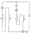
도 3A 및 3B는 115V와 220V의 출력 전압 각각에 대한 본 발명의 권선 스위칭 회로 및 열 보호를 위한 배열의 제1 실시 예를 나타낸 것이다. 동일한 전기 구성부품이 두 개의 배열에서 사용됨을 알아야하고, 단지 구성부품사이의 전기적 연결만이 스위치의 개폐에 의하여 하나의 배열에서 다른 배열로 변환된다. Figures 3A and 3B illustrate a first embodiment of an inventive winding switching circuit and array for thermal protection for an output voltage of 115V and 220V, respectively. It should be noted that the same electrical components are used in two arrangements, only electrical connections between the components are converted from one arrangement to another by opening and closing the switches.
본 발명에 따른 회로는 종래기술의 회로에 사용된 세 가지 핀 대신에 밀폐 단자에서 다섯 개의 연결 핀 1, 2, 3, 4, 5를 사용한다. 회로는 두 개의 코일(M1과 M2)을 가진 주권선 및 보조 권선(A)을 포함한다. 도 3A 및 3B에서, 주권선(M1과 M2)의 각 코일은 모터의 두 극을 나타내는 두 개의 독립된 코일 부분(M1a, M1b, M2a, M2b)으로 표시된다. 보조 권선 코일은 역시 두 개의 독립된 코일(Aa와 Ab)로 표시된다. 회로는 배열 각각(115V 또는 220V 출력)에 대해 원하는 연결을 바탕으로 연결되게, 연결되지 않도록 하는 스타트업 릴레이(R)와 세 개의 스위치(R1, R2, R3)를 포함한다. 또한, 회로는 회로의 다른 구성부품과 연결되어 있는 열 보호 수단을 포함하며, 그래서 115V와 220V의 배열 모두에서 제1 및 제2 주권선(M2, M1)의 과열에 대하여 열 보호를 수행한다. 열 보호 수단은 하나의 열 삼상 보호기(P)의 형태 또는 두 개의 독립적인 열보호기(P1, P2)의 형태가 있을 수 있다.The circuit according to the invention uses five
도 3A, 3B에 도시된 회로 배열에서, 하나 이상의 장치에 연결된 회로점(5, 6, 7)은 회로 연결의 이해를 용이하게 하기 위하여 노드(N1, N2, N3, N4 및 N5)로 정의된다.In the circuit arrangement shown in Figures 3A and 3B, circuit points 5, 6 and 7 connected to one or more devices are defined as nodes N1, N2, N3, N4 and N5 to facilitate understanding of circuit connections .
두 배열에서의 회로의 기본적인 기능은 도 3A, 3B에 볼 수 있듯이 스위치(R1, R2, R3)가 개방되거나 닫힘에 따라 변화한다. 그러나, 앞서 기술한 회로의 연결은 두 개의 바람직한 동작 배열에 공통이다.The basic function of the circuit in both arrangements changes as the switches R1, R2, R3 open or close, as can be seen in Figures 3A and 3B. However, the connections of the circuits described above are common to the two preferred operating arrangements.
독립적인 코일(M1a, M1b)로 표시된 주권선(M1)의 제1 코일은 음극이 제1 노드(N1)에 연결되고, 양극은 제2 노드(N2)에 연결되어 배치된다. 이 제1 주 코일은 핀(1)과 핀(2)사이에 연결되고, 음극은 핀(1)에 연결되고 양극은 핀(2)에 연결된다. The first coil of the main winding line M1 denoted by the independent coils M1a and M1b has a cathode connected to the first node N1 and an anode connected to the second node N2. The first main coil is connected between the
독립적인 코일(M2a, M2b)로 표시된 주권선(M2)의 제2 코일은 양극이 제3 노드(N3)에 연결되고, 음극은 제4 노드(N4)에 연결되어 배치된다. 코일(M2a)의 양극은 역시 밀폐된 단자의 핀(3)에 연결된다.The second coil of the main winding line M2 indicated by the independent coils M2a and M2b has the anode connected to the third node N3 and the cathode connected to the fourth node N4. The anode of the coil M2a is also connected to the
독립적인 코일(Aa, Ab)로 표시된 보조 권선(A)은 양극이 스타트업 릴레이(R)에 연결되고, 음극은 제4 노드(N4)에 연결되어 배치된다. 스타트업 릴레이(R)는 제3 노드(N3)에 연결된다. 따라서, 보조 권선(A)은 제2 주권선(M2)에 병렬로 연결된다. 밀폐된 단자의 핀(4)는 스타트업 릴레이와 코일(Aa)의 양극사이에 연결된다. The auxiliary winding A indicated by the independent coils Aa and Ab is connected to the start-up relay R and the cathode is connected to the fourth node N4. The start-up relay R is connected to the third node N3. Thus, the auxiliary winding A is connected in parallel to the second main winding line M2. The pin (4) of the closed terminal is connected between the start-up relay and the anode of the coil (Aa).
제1 스위치(R1)은 제2 노드(N2)와 제3 노드(N3)사이에 연결된다. 제2 스위치(R2)은 제3 노드(N3)와 제1 노드(N1)사이에 연결된다. 제3 스위치(R3)은 제1 노드(N1)와 제5 노드(N5)사이에 연결된다. 핀(5)은 제4 노드(N4)와 제5 노드(N5) 사이에 위치한다. 전압 소스는 제2 노드(N2)와 제5 노드(N5)사이에 연결된다.The first switch R1 is connected between the second node N2 and the third node N3. The second switch R2 is connected between the third node N3 and the first node N1. The third switch R3 is connected between the first node N1 and the fifth node N5. The
앞서 정의된 연결은 115 V와 220V의 출력 배열로 도 3a, 도3b, 도5, 도6 및 도 7에 도시되고 여기에 기술된 본 발명의 4개의 실시 예 모두에 적용된다. 각각의 실시 예사이에서 변화하는 것은 오직 열 보호 수단과의 연결 뿐이다.The connections defined above apply to all four embodiments of the present invention illustrated in Figures 3a, 3b, 5, 6, and 7 and described herein with an output arrangement of 115 V and 220V. Only the connection with the thermal protection means changes between the respective embodiments.
본 발명에 따른 제1 실시 예에서, 두 개의 독립적인 열보호기(P1과 P2)가 사용된다. 제1 열보호기(P1)는 제2 노드(N2)와 밀폐형 단자의 핀(1)사이에 연결되고, 그래서 제1 주권선의 양극에 연결된다. 제2 열보호기(P2)는 제4 노드(N4)와 제5 노드(N5)사이에 연결되며, 그래서 제2 주권선(M2)와 보조 권선(A)의 음극에 연결된다.In a first embodiment according to the present invention, two independent thermal protectors (P1 and P2) are used. The first row protector P1 is connected between the second node N2 and the
도 3A에 도시된 115 V 출력 배열에서, 제1 스위치(R1)와 제3 스위치(R3)가 연결되고, 제2 스위치(R2)는 연결되지 않는다. 제3 스위치(R3)가 닫혀 있기 때문에(연결됨), 노드(N1)와 노드(N5)는 함께 연결되어 있고 제2 열 보호기(P2)는 핀(2)과 핀(5)사이에 연결된다. 또한, 연결된 스위치(R1)는 노드(N2)와 노드(N3)사이에 짧은 회로를 형성한다. 이러한 배열에 의해, 코일(M1)과 코일(M2)은 병렬이다. 보조 코일(A)은 역시 메인 코일(M1)과 메인 코일(M2)와 병렬이다. 그래서 모든 코일(M1, M2 및 A)은 전압 소스가 연결되어 있는 노드(N2)와 노드(N5)(또는 노드(N5)와 단락된 노드(N1)) 사이에 병렬로 연결되어 있기 때문에, 모든 코일에 일반적으로 약 115V로 동일한 소스 전압이 제공된다. 이 배열에서, 각 열보호기(P1과 P2)는 주 코일(P1은 M1을 보호하고, P2는 M2를 보호함)의 분지(branch)를 보호할 것이다. 주 코일(M1과 M2)의 극은 열보호기(P1)가 두 극 사이에 연결되어 있기 때문에 서로 직접 연결되지 않음을 알 수 있다. 따라서, 극의 수는 220V 출력 배열에서와 같이 115V 배열에서도 둘 다 동일하게 유지한다. In the 115 V output arrangement shown in FIG. 3A, the first switch Rl and the third switch R3 are connected, and the second switch R2 is not connected. The node N1 and the node N5 are connected together and the second thermal protector P2 is connected between the
220V의 출력 연결에서, 회로 구성 부품 사이의 연결에서의 변경은 스위치의 상태 변화에 의해 발생한다. 스위치(R1)와 스위치(R3)는 끊김/개방에 있고, 단지 스위치(R2)만 연결/닫힘에 있다. 따라서, 노드(N1)와 노드(N3)는 단락 회로로 연결되어 있다. 밀폐 단자의 핀(2)은 이후 스타트업 릴레이(R)와 핀(3)에 연결되어 있다. 스위치 (R1)가 개방되어 있기 때문에, 노드(N2)와 노드(N3)는 함께 연결되어 있지 않다. 또한, 제3 스위치(R3)를 개방하므로, 노드(N1)과 노드(N5)는 서로 연결되지 않으며, 그래서 제1 주 코일(M1)의 음극은 더 이상 전압 소스의 음극에 연결되지 않는다. 따라서, 코일(M1)과 코일(M2)는 직렬로 연결된다. 보조 코일(A)는 핀(4)과 스타트업 릴레이(R)에 연결되어 있지만, 스위치(R1)은 개방되고 스위치(R2)는 닫혀 있기 때문에, 보조코일(A)의 양극은 이후 제1 주 코일(M1)의 음극과 제2 주 코일(M2)의 양극 사이의 지점, 보다 구체적으로 제3 노드에서 코일(M1)과 코일(M2)사이의 전압 분지점에서 핀(4)와 스타트업 릴레이(R)에 의해 연결된다. 따라서, 보조 코일은 각 코일의 설계에 따라 두 주 코일(M1과 M2)의 전압 분배기에 상응하는 약 115V 또는 근사치의 전압을 제공한다. 이 배열에서, 스위치(R1)과 스위치(R3)가 연결되지 않고, 단지 제2 노드(N2)는 전원장치의 양극에 연결되며, 결과적으로 제1 열보호기(P1)는 전원 공급 장치와 제1 주 코일(M1)의 (+)단자 사이에 연결된다. 전원 공급 장치의 음극은 모두 직렬로 제5 노드(N5), 열보호기(P2), 핀(5), 마지막으로 제4 노드(N4)에 연결된다. 주권선(M2)과 보조권선(A)의 음극은 또한 제4 노드(N4)에 연결되며, 그래서 제4 노드(N4)와 직렬로 연결된 제2 열보호기(P2)에 의해 보호된다. 따라서 220V 출력 전압은 단지 주권선(M1 및 M2)과 직렬로 연결되어 적용된다. 보호기(P1 및 P2)는 코일(M1)과 코일(M2)에 직렬로 연결되며, 둘 다 동시에 보호한다.At an output connection of 220V, the change in the connection between the circuit components is caused by a change in the state of the switch. Switches R1 and R3 are in the open / closed state, and only the switch R2 is in the closed / closed state. Therefore, the node N1 and the node N3 are short-circuited. The pin (2) of the closed terminal is then connected to the start-up relay (R) and pin (3). Since the switch R1 is open, the node N2 and the node N3 are not connected together. Further, since the third switch R3 is opened, the node N1 and the node N5 are not connected to each other, so that the cathode of the first main coil M1 is no longer connected to the cathode of the voltage source. Thus, the coil M1 and the coil M2 are connected in series. The auxiliary coil A is connected to the
본 발명은 또한 115V와 220V의 두 배열에서 회로에 열보호기를 연결하는 일부 변형된 형태를 허용하여 모터의 주 코일의 두 분지(branch)에 대해 동일한 독립적인 보호 목적을 달성한다. The present invention also allows some modified forms of connecting thermal protectors to the circuit in both arrangements of 115V and 220V to achieve the same independent protection objectives for the two branches of the motor's main coil.
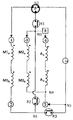
도 5와 같이 다른 배열에서, 열 보호는 세 개의 단자를 가진 단일 열 삼상 보호기(P)의 사용에 의하여 수행되며, 그래서 제1 단자는 밀폐된 단자의 핀(1)과 제1 주권선(M1)의 양극과 연결되며, 제2 단자는 제1 스위치(R1)와 전원 공급 장치의 양극에 연결된 제3 단자와 연결된다. 이러한 열보호기는 제2 노드(N2)의 위치에 위치할 수 있다. 제1 스위치(R1)가 약 115V를 가진 출력 배열에서 닫혔을 때, 열 삼상 보호기는 주권선(M1과 M2) 모두의 양극에 연결된다. 제1 스위치(R1)가 개방되고, 제2 스위치(R2)가 닫힐 때, 열 보호기(P)는 전원 공급 장치의 양극과 제1 권선(M1)의 양극 사이에 연결되며, 스위치(R2)에 의해 직렬로 연결된 두 개의 주권선(M1)의 보호를 수행한다. 5, thermal protection is performed by use of a single-row three-phase protector P having three terminals, so that the first terminal is connected to the
도 6에서 보여주는 본 발명의 또 다른 변형 배열에서, 열 보호는 P1은 115V에 맞도록 규격화되고, P2는 220V의 전류에 맞도록 규격화하여 각 전압에 전용의 두 열보호기(P1 및 P2)를 사용함으로써 수행된다. 제1 열 보호기(P1)는 전원 공급 장치의 양극과 제2 노드(N2)사이에 연결되고, 또한 제1 주권선(M1)의 양극에 연결된다. 제2 열 보호기(P2)는 제1 스위치(R1)과 제2 스위치(R2)사이에 연결되고, 제3 노드(N3)와 제2 스위치(R2)사이에 위치할 수 있다. 따라서, 스위치는 제1 스위치(R1)와 제3 스위치(3)를 닫고 제2 스위치(R2)를 열어서 115V 연결을 위해 배열 될 때, 보호기(P2)는 제2 스위치(R2)가 연결되지 않아서 회로를 벗어나게 되고, 회로에서 단일한 보호기는 전원 공급 장치와 직렬로 연결된 P1이 될 것이다. 반면에 스위치가 220V 연결을 위하여 배열된 (제1(R1) 및 제3(R3) 스위치는 개방되고, 제2(R2) 스위치가 닫힘) 보호기(P2)가 두 개의 주권선(M1 및 M2)사이에 직렬로 연결되어 활성화될 것이며, 보호기(P1)는 회로 내에 있다 할지라도 규격화된(sized) 아주 낮은 전류 때문에 활발한 기능을 가지지 못할 것이다. In another variation of the invention shown in FIG. 6, thermal protection is standardized such that P1 is adapted to 115V and P2 is standardized to 220V and two dedicated thermal protectors P1 and P2 are used for each voltage . The first heat protector P1 is connected between the positive electrode of the power supply device and the second node N2 and is also connected to the positive electrode of the first main winding line M1. The second thermal protection unit P2 may be connected between the first switch R1 and the second switch R2 and may be located between the third node N3 and the second switch R2. Thus, when the switch is arranged for a 115V connection by closing the first switch R1 and the
도 7에서 보여주는 본 발명의 또 다른 변형 배열에서, 도 6의 배열에서와 같은 원리가 사용되지만, 그러나 보호기(P1)의 전원 공급 장치의 음극과 노드(N5) 사이에 연결되고, 제2 보호기(P2)는 제4 노드(N4)와 제5 노드(N5)사이에 연결된다. 115V의 출력 배열에서, 스위치(R1과 R3)가 닫히고, 스위치(R2)는 개방되며, 제2 열보호기(P2)는 제2 주권선(M2)을 보호하고, 제1 열보호기(P1)는 제1 주권선(M1)을 보호한다. 220V의 출력 배열에서, 스위치(R1과 R3)가 개방되고, 스위치(R2)가 닫히며, 제1 및 제2 열보호기(P1과 P2)는 직렬로 연결되고, 이후 제1 및 제2 주권선(M1과 M2)으로 두 권선의 열 보호를 수행한다.7, the same principle as in the arrangement of Fig. 6 is used, but connected between the cathode of the power supply of the protector P1 and the node N5, and the second protector (Fig. 7) P2 are connected between the fourth node N4 and the fifth node N5. In the output arrangement of 115V, the switches R1 and R3 are closed and the switch R2 is opened, the second heat protector P2 protects the second main power line M2, and the first heat protector P1 Protects the first main power line M1. In the output arrangement of 220V, the switches R1 and R3 are opened, the switch R2 is closed, the first and second thermal protectors P1 and P2 are connected in series, then the first and second main- (M1 and M2) to perform thermal protection of the two windings.
비록 상기 배열이 115V와 220V에 가까운 값에 적당할지라도, 회로는 90V와 260V사이의 전체 전압 범위에서 동작한다.Although the arrangement is suitable for values close to 115V and 220V, the circuit operates over the entire voltage range between 90V and 260V.
열 보호기(P1과 P2)는 주 코일(M1 및 M2)과 직접 접촉으로 회로의 쉘 내부에 배치될 수 있다. 본 발명의 실시 예에서 열 보호기로 사용되는 장치는 온도에 민감하며, 그들의 배치(disposition) 덕분에 그들이 직접 코일의 온도 수준을 감지하고, 온도가 특정 임계값에 도달하면 회로를 개방하여 코일의 과열을 방지한다.The thermal protectors P1 and P2 may be disposed inside the shell of the circuit in direct contact with the main coils M1 and M2. Devices used as thermal protectors in embodiments of the present invention are sensitive to temperature and because of their disposition they directly sense the temperature level of the coil and when the temperature reaches a certain threshold the circuit is opened to overheat the coil .
또한, 열 보호기(P1과 P2)는 회로의 쉘의 외부에 배치되고, 바람직하게는 쉘과 함께 압축기의 외측에 고정된다. 이러한 열 보호기는 일반적으로 쉘의 온도와 압축기의 전류를 모니터링함으로써 가능하며, 쉘의 온도 및/또는 압축기의 전류가 임계값을 초과할 때, 보호기는 개방되고 회로를 인터럽트(interrupt)한다. 바람직한 형태로, 압축기의 전류는 열 보호기의 내부 회로를 통과하여 흐르고 바이메탈 바로 하부에 배치되는 저항을 가열한다. 전류가 낮은 경우에 저항의 발열도 낮고, 따라서 바이메탈 디스크를 가열하는 것이 충분하지 않다. 그러나, 압축기의 전류가 증가하고 회로의 과열에 해당하는 임계값을 초과할 때, 바이메탈 디스크 역시 더 가열되어 휘게 되고, 회로를 개방하여 전류를 인터럽트한다.In addition, the heat protectors P1 and P2 are disposed outside the shell of the circuit, and are preferably fixed to the outside of the compressor together with the shell. Such a thermal protector is typically accomplished by monitoring the temperature of the shell and the current of the compressor, and when the temperature of the shell and / or the current of the compressor exceeds a threshold, the protector is opened and interrupts the circuit. In a preferred form, the current in the compressor flows through the internal circuitry of the thermal protector and heats the resistors disposed directly beneath the bimetal. When the current is low, the resistance is also low, and therefore heating the bimetal disc is not sufficient. However, when the current of the compressor increases and exceeds the threshold value corresponding to the overheating of the circuit, the bimetal disc is further heated and bent, and the circuit is opened to interrupt the current.
본 발명에 따르면, 회로에서 사용되는 스위치(R1, R2 및 R3)는 기계적으로 구동되는 수동 스위치일 수 있다. 예를 들어, 출력 전압에 따라 개방 또는 닫히는 솔리드 상태 소자 같은 전자 스위치 또한 사용될 수 있으며, 또는 스위치(R1, R2, R3)는 전자회로 방식에 의하여 제어되는 전자 기계식 릴레이일 수 있다.According to the invention, the switches R1, R2 and R3 used in the circuit can be mechanically driven manual switches. For example, an electronic switch such as a solid state device that is open or closed depending on the output voltage may also be used, or the switches R1, R2, R3 may be electromechanical relays controlled by electronic circuitry.
도 4는 주 코일(M1과 M2)의 코일이 모터에 두 개의 독립적인 코일 부품(M1a, M1b, M2a, M2b)의 형태로 배치되는 방법을 보여준다. 일반적으로 이러한 독립적인 코일 부품은 와이어의 인터럽션 없이 순서대로 코일된다. 그러나, 본 발명에 따르면, 주권선의 각 코일(M1, M2)은 두 개의 같은 독립적인 부품(M1a, M1b; M2a, M2b)으로 나누어야 한다. 그루브(groove)당 같은 수의 코일을 포함하는 동일 코일의 독립적인 부품은 직렬로 연결되어 각각 고정자의 한 면에 배치되어 있다. 따라서, 각 권선의 각각의 절반에 의해 생성된 자기장 흐름이 균형을 이룬다.Figure 4 shows how the coils of the main coils M1 and M2 are arranged in the motor in the form of two independent coil parts M1a, M1b, M2a and M2b. Typically, these independent coil components are coiled in sequence without interruption of the wire. However, according to the present invention, each coil M1, M2 of the main winding line must be divided into two identical independent parts M1a, M1b, M2a, M2b. Independent parts of the same coil, including the same number of coils per groove, are connected in series and arranged on one side of the stator, respectively. Thus, the magnetic field flow produced by each half of each winding is balanced.
따라서, 제1 분지(M1, branch)는 두 부분으로 세분화되고, 제1 코일의 제1 부품(M1a)은 고정자의 한쪽 측면에 배치되고 제1 코일의 제2 부품(M1b)은 고정자의 반대 측면에 배치된다. 제2 분기의 두 개의 코일은 같은 방식으로 배치되고, 제1 부품(M2a)은 제1 코일의 제1부품(M1a)로 고정자의 동일한 측면에 배치되며, 제2 코일의 제2 부품(M2b)은 제1 코일의 제2 부품(M1b)으로 동일한 측면에 배치된다. 보조 권선은 변경되지 아니하고, 직렬로 연결된 각 극의 코일에 남아있다. 이러한 배치는 성능 손실 및 하모닉 토크의 생성을 이끌 수 있는 고정자 극 사이의 흐름의 불균형이 없게 한다.The first part M1a of the first coil is disposed on one side of the stator and the second part M1b of the first coil is disposed on the opposite side of the stator . Two coils of the second branch are arranged in the same manner and the first part M2a is arranged on the same side of the stator as the first part M1a of the first coil and the second part M2b of the second coil is arranged on the same side of the stator, Is disposed on the same side as the second part M1b of the first coil. The auxiliary winding remains unchanged and remains in the coils of each pole connected in series. This arrangement eliminates the imbalance of flow between the stator poles, which can lead to performance losses and the generation of harmonic torque.
본 발명의 권선 스위칭 회로와 열 보호의 주된 이점은 240~220의 범위에서와 같이 115~127V의 범위의 전압에 대해서도 예를 들어, 코일, 스타트업 릴레이, 커패시터(미도시) 및 열 보호기 같은 동일한 전기 장치를 사용할 수 있다는 것과, 관리의 용이함, 구성 부품의 재고 감소, 엔지니어링 코드 수 감소, 생산 및 유통 물류의 용이함이다. 또한, 이 회로는 열 보호기가 쉘의 내부적으로 또는 외부적으로 배치되어 단지 스위치(R1,R2,R3)를 닫거나 열어서 220V용에서와 같이 115V 용에서도 동작하며, 주권선(M1과 M2)의 열 보호를 권선의 각각에 대해 분리 수행될 수 있게 허용한다.The main advantage of the winding switching circuit and thermal protection of the present invention is that even for voltages in the range of 115 to 127 volts, such as in the range of 240 to 220, the same can be achieved, for example, in the same way as coils, start-up relays, capacitors (not shown) Ease of management, reduced inventory of component parts, reduced number of engineering codes, and ease of production and distribution logistics. This circuit also allows the heat protectors to be placed internally or externally of the shell to close or open the switches R1, R2 and R3 and to operate for 115V as for 220V, Allowing protection to be performed separately for each of the windings.
바람직한 실시 예를 설명했으며, 본 발명의 범위는 첨부된 청구의 내용에 의해 제한되며, 그들이 포함하고 있는 균등물, 다른 가능한 변형이 포함되는 것으로 이해되어야 한다.It is to be understood that the scope of the invention is limited only by the appended claims and that they include equivalent and other possible modifications that they include.
Claims (13)
제1 주권선(M1)은 음극은 제1 노드(N1)와 연결되고, 양극은 제2 노드(N2)에 연결되며,
제2 주권선(M2)은 양극은 제2 노드(N3)와 연결되고, 음극은 제4 노드(N4)에 연결되며,
제1 스위치(R1)는 제2 노드(N2)와 제3 노드(N3)사이에 연결되고, 스타트업 릴레이(R)는 제3 노드(N3)에 연결되며,
보조 권선(A)은 양극이 스타트업 릴레이(R)에 연결되며, 음극은 제4 노드(N4)에 연결되고, 보조 권선(A)은 제2 주권선과 병렬로 연결되며,
제2 스위치(R2)는 제3 노드(N3)와 제1 노드(N1)사이에 연결되고,
제3 스위치(R3)는 제1 노드(N1)와 제5 노드(N5)사이에 연결되며,
전압 소스는 제2 노드(N2)와 제5 노드(5)사이에 연결되고,
회로는 제1 및 제2 배열에서 작동하고, 제1 배열에서, 제1 스위치(R1)와 제 3 스위치(R3)가 연결되며, 제2 스위치가 연결되지 않고, 제1 주권선(M1), 제2 주권선(M2) 및 보조 권선(A)은 병렬로 연결되며,
제2 배열에서, 제1 스위치(R1)와 제3 스위치(R3)는 연결되지 않으며, 제2 스위치(R2)는 연결되고, 제1 주권선(M1)과 제2 주권선(M2)이 직렬로 연결되며, 보조권선(A)은 단지 제2 주권선(M2)과 병렬로 연결되고,
회로는 제1 및 제2 배열에서 제1 및 제2 주권선(M1, M2)의 열적 보호를 수행하는 열적 보호 수단을 포함하는 단상 이중 전압 밀폐형 유도 모터를 위한 열 보호 및 권선 스위칭회로.CLAIMS 1. A thermal protection and winding switching circuit for a single phase, double-voltage hermetically sealed induction motor of a hermetically sealed compressor,
In the first main winding line M1, the cathode is connected to the first node N1, the anode is connected to the second node N2,
In the second main winding line M2, the anode is connected to the second node N3, the cathode is connected to the fourth node N4,
The first switch R1 is connected between the second node N2 and the third node N3 and the start-up relay R is connected to the third node N3,
The auxiliary winding A has an anode connected to the start-up relay R, a cathode connected to the fourth node N4, an auxiliary winding A connected in parallel with the second main winding,
The second switch R2 is connected between the third node N3 and the first node N1,
The third switch R3 is connected between the first node N1 and the fifth node N5,
The voltage source is connected between the second node N2 and the fifth node 5,
The circuit operates in the first and second arrangements and in the first arrangement the first switch R1 and the third switch R3 are connected and the second switch is not connected and the first main winding M1, The second main winding line (M2) and the auxiliary winding (A) are connected in parallel,
In the second arrangement, the first switch R1 and the third switch R3 are not connected, the second switch R2 is connected, and the first main winding line M1 and the second main winding line M2 are connected in series The auxiliary winding A is connected in parallel with the second main winding line M2 only,
Circuit comprises a thermal protection means for performing thermal protection of the first and second mains lines (M1, M2) in the first and second arrangements. A thermal protection and winding switching circuit for a single phase double-voltage hermetically sealed induction motor.
회로는 90V와 260V 사이의 전압 범위에서 동작하며, 제1 배열은 115V 가까운 전압 범위에서 동작하며, 제2 배열은 220V 가까운 전압 범위에서 동작함을 특징으로 하는 열 보호 및 권선 스위칭회로.The method according to claim 1,
Wherein the circuit operates in a voltage range between 90V and 260V and the first arrangement operates in a voltage range close to 115V and the second arrangement operates in a voltage range close to 220V.
열 보호 수단은 세 개의 단자를 갖는 단일 열 삼상 보호기(P), 하나의 단자는 제1 주권선(M1)의 양극에 연결되고, 하나의 단자는 제1 스위치(R1)에 연결되며, 하나의 단자는 전원 공급 장치의 양극에 연결됨을 특징으로 하는 열 보호 및 권선 스위칭회로.The method according to claim 1 or 2,
The thermal protection means comprises a single-phase three-phase protector P having three terminals, one terminal connected to the anode of the first main winding M1, one terminal connected to the first switch R1, Terminal is connected to the anode of the power supply.
열 보호 수단은 전원 공급 장치의 양극과 제2 노드(N2)사이에 연결된 제1 열 보호기(P1)와 제1 스위치(R1)와 제2 스위치(R2)사이에 연결된 제2 열 보호기를 포함함을 특징으로 하는 열 보호 및 권선 스위칭회로.The method according to claim 1 or 2,
The thermal protection means includes a first thermal protector P1 connected between the anode of the power supply and the second node N2 and a second thermal protector connected between the first switch R1 and the second switch R2 And a winding switching circuit.
열 보호 수단은 제1 주권선(M1)의 양극과 제2 노드(N2)사이에 연결된 제1 열 보호기(P1)와 제4 노드(N4)와 제5 노드(N5)사이에 연결된 제2 열 보호기(P2)를 포함함을 특징으로 하는 열 보호 및 권선 스위칭회로.The method according to claim 1 or 2,
The thermal protection means includes a first column protection unit P1 connected between the anode of the first main winding line M1 and the second node N2 and a second column protection unit P1 connected between the fourth node N4 and the fifth node N5. And a protective group (P2).
열 보호 수단은 전원 공급 장치의 음극과 제5 노드(N5)사이에 연결된 제1 열 보호기(P1)와 제4 노드(N4)와 제5 노드(N5)사이에 연결된 제2 열 보호기를 포함함을 특징으로 하는 열 보호 및 권선 스위칭회로.The method according to claim 1 or 2,
The thermal protection means includes a first thermal protector P1 connected between the cathode of the power supply and the fifth node N5 and a second thermal protector connected between the fourth node N4 and the fifth node N5. And a winding switching circuit.
열 보호 수단(P;P1,P2)은 주권선(M1, M2)과 접촉하는 회로의 쉘 내부에 배치되고, 권선의 온도가 임계값을 초과 할 때 개방함을 특징으로 하는 열 보호 및 권선 스위칭회로.The method according to any one of claims 1 to 6,
Characterized in that the thermal protection means (P1; P2) are arranged inside the shell of a circuit in contact with the main winding lines (M1, M2) and open when the temperature of the windings exceeds a threshold value. Circuit.
열 보호 수단(P;P1,P2)은 회로의 쉘 외부에 배치되고, 압축기의 전류 또는 온도가 임계값을 초과할 때 개방함을 특징으로 하는 열 보호 및 권선 스위칭회로.The method according to any one of claims 1 to 6,
Characterized in that the thermal protection means (P; P1, P2) are arranged outside the shell of the circuit and open when the current or temperature of the compressor exceeds a threshold value.
스위치(R1, R2, R3)는 기계적으로 구동함을 특징으로 하는 열 보호 및 권선 스위칭회로.The method according to any one of claims 1 to 8,
Characterized in that the switches (R1, R2, R3) are mechanically driven.
스위치(R1, R2, R3)는 전자스위치임을 특징으로 하는 열 보호 및 권선 스위칭회로.The method according to any one of claims 1 to 8,
Characterized in that the switches (R1, R2, R3) are electronic switches.
스위치(R1, R2, R3)는 전자 회로에 의해 제어되는 전자기계식 릴레이임을 특징으로 하는 열 보호 및 권선 스위칭회로.The method according to any one of claims 1 to 8,
Characterized in that the switches (R1, R2, R3) are electromechanical relays controlled by electronic circuits.
제1 및 제2 주권선(M1, M2)은 두 개의 독립적인 코일부품(Ma1,Mb1,Ma2,Mb2)으로 각각 나누어 직렬로 연결되고, 동일한 권선의 각 코일 부분은 고정자의 한 측면에 배치됨을 특징으로 하는 열 보호 및 권선 스위칭회로.The method according to any one of claims 1 to 11,
The first and second main windings M1 and M2 are connected in series to two independent coil parts Ma1, Mb1, Ma2 and Mb2, and each coil part of the same winding is arranged on one side of the stator Features a thermal protection and winding switching circuit.
밀폐 다섯 핀 단자(1,2,3,4,5)로 구성된 압축기의 밀폐된 쉘 내부에 배치되며,
여기서, 제1 핀(1)은 제1 주권선(M1)의 양극에 위치하고,
제2 핀(2)은 제1 주권선(M1)의 음극과 제1 노드(N1)사이에 연결되며,
제3 핀(3)은 제2 주권선(M2)의 양극과 제3 노드(N3)사이에 연결되고,
제4 핀(4)은 보조 권선(A)의 양극과 스타트업 릴레이(R)사이에 연결되며, 제5 핀(5)은 제5 노드(N5)와 제4 노드(N4)사이에 위치함을 특징으로 하는 열 보호 및 권선 스위칭회로.The method according to any one of claims 1 to 11,
(1, 2, 3, 4, 5) of the compressor,
Here, the first pin 1 is located at the anode of the first main winding line M1,
The second fin (2) is connected between the cathode of the first main winding line (M1) and the first node (N1)
The third pin 3 is connected between the anode of the second main winding line M2 and the third node N3,
The fourth pin 4 is connected between the anode of the auxiliary winding A and the start up relay R and the fifth pin 5 is located between the fifth node N5 and the fourth node N4 And a winding switching circuit.
Applications Claiming Priority (3)
| Application Number | Priority Date | Filing Date | Title |
|---|---|---|---|
| BRPI1101882-8A BRPI1101882A2 (en) | 2011-02-25 | 2011-02-25 | winding and thermal protection switching circuit for induction motor hermetic refrigeration hermetic compressor |
| BRPI1101882-8 | 2011-02-25 | ||
| PCT/BR2012/000039 WO2012113048A2 (en) | 2011-02-25 | 2012-02-24 | Winding switching circuit and thermal protection for dual voltage hermetic induction motor of hermetic cooling compressor |
Publications (1)
| Publication Number | Publication Date |
|---|---|
| KR20140052975A true KR20140052975A (en) | 2014-05-07 |
Family
ID=45930524
Family Applications (1)
| Application Number | Title | Priority Date | Filing Date |
|---|---|---|---|
| KR1020137024002A KR20140052975A (en) | 2011-02-25 | 2012-02-24 | Winding switching circuit and thermal protection for dual voltage hermetic induction motor of hermetic cooling compressor |
Country Status (8)
| Country | Link |
|---|---|
| JP (1) | JP2014508493A (en) |
| KR (1) | KR20140052975A (en) |
| CN (1) | CN103503302A (en) |
| BR (1) | BRPI1101882A2 (en) |
| CO (1) | CO6870007A2 (en) |
| MX (1) | MX2013009819A (en) |
| SA (1) | SA112330301B1 (en) |
| WO (1) | WO2012113048A2 (en) |
Families Citing this family (8)
| Publication number | Priority date | Publication date | Assignee | Title |
|---|---|---|---|---|
| BR102012029646A2 (en) * | 2012-11-21 | 2014-09-23 | Whirlpool Sa | PROTECTION AND CONTROL SYSTEM AND METHOD FOR BIVOLT AND COMPRESSOR ENGINES |
| BR102012030933A2 (en) | 2012-12-04 | 2014-09-09 | Whirlpool Sa | CIRCUIT AND PROTECTION DEVICE FOR INDUCTION MOTORS, INDUCTION MOTOR AND CONTROL AND PROTECTION SYSTEM FOR A INDUCTION MOTOR |
| EP3306808A4 (en) * | 2015-05-29 | 2019-01-02 | Koki Holdings Co., Ltd. | Electric tool |
| DE102016216041A1 (en) * | 2016-08-25 | 2018-03-01 | Robert Bosch Gmbh | Method and control device for heating a device driven by a brushless DC motor |
| CN107947677B (en) * | 2017-12-11 | 2020-07-28 | 利欧集团浙江泵业有限公司 | Double-voltage self-adaptive single-phase double-speed double-voltage asynchronous motor |
| BR102017028389A2 (en) * | 2017-12-28 | 2019-07-16 | Robert Bosch Limitada | ELECTRICAL SWITCHING SYSTEM FOR DYNAMO-ELECTRIC MACHINE AND ELECTRIC TOOL PROVIDED FROM ELECTRICAL SWITCHING FOR DYNAMO-ELECTRIC MACHINE |
| CN108712020A (en) * | 2018-05-25 | 2018-10-26 | 苏州优德通力科技有限公司 | A kind of thermel protection device of single-phase dual-voltage motor |
| US11382484B2 (en) | 2020-01-23 | 2022-07-12 | Haier Us Appliance Solutions, Inc. | Dishwashing appliance and electric motor for a fluid pump with a thermal-protection assembly |
Family Cites Families (9)
| Publication number | Priority date | Publication date | Assignee | Title |
|---|---|---|---|---|
| US2734158A (en) * | 1956-02-07 | Protective arrangement for dual- | ||
| GB632468A (en) | 1946-11-21 | 1949-11-28 | Westinghouse Electric Int Co | Improvements in or relating to single-phase induction motors |
| DE1663114B1 (en) * | 1965-01-20 | 1970-01-15 | Danfoss As | Electric motor with resistance auxiliary phase |
| US3821602A (en) * | 1972-11-20 | 1974-06-28 | Gen Electric | Thermally protectable multispeed motor |
| US4387330A (en) * | 1980-09-19 | 1983-06-07 | General Electric Company | Balanced single phase alternating current induction motor |
| JPS61102189A (en) | 1984-10-22 | 1986-05-20 | Hitachi Ltd | Voltage response type circuit automatic switching type motor driven pump |
| US5013990A (en) * | 1989-10-16 | 1991-05-07 | Weber Harold J | Energy conserving electric motor power control method and apparatus |
| US5867005A (en) | 1997-12-18 | 1999-02-02 | Comair Rotron, Inc. | AC motor winding circuit |
| CN101917146A (en) * | 2010-07-16 | 2010-12-15 | 杭州泛博电器有限公司 | Novel zero-power PTC starter for small refrigerating compressor |
-
2011
- 2011-02-25 BR BRPI1101882-8A patent/BRPI1101882A2/en not_active IP Right Cessation
-
2012
- 2012-02-24 WO PCT/BR2012/000039 patent/WO2012113048A2/en active Application Filing
- 2012-02-24 MX MX2013009819A patent/MX2013009819A/en active IP Right Grant
- 2012-02-24 KR KR1020137024002A patent/KR20140052975A/en not_active Application Discontinuation
- 2012-02-24 CN CN201280020244.5A patent/CN103503302A/en active Pending
- 2012-02-24 JP JP2013554754A patent/JP2014508493A/en active Pending
- 2012-02-25 SA SA112330301A patent/SA112330301B1/en unknown
-
2013
- 2013-09-25 CO CO13228226A patent/CO6870007A2/en not_active Application Discontinuation
Also Published As
| Publication number | Publication date |
|---|---|
| CN103503302A (en) | 2014-01-08 |
| SA112330301B1 (en) | 2015-02-18 |
| WO2012113048A8 (en) | 2013-03-14 |
| WO2012113048A3 (en) | 2013-05-02 |
| MX2013009819A (en) | 2013-10-17 |
| CO6870007A2 (en) | 2014-02-20 |
| JP2014508493A (en) | 2014-04-03 |
| WO2012113048A2 (en) | 2012-08-30 |
| BRPI1101882A2 (en) | 2013-05-28 |
Similar Documents
| Publication | Publication Date | Title |
|---|---|---|
| KR20140052975A (en) | Winding switching circuit and thermal protection for dual voltage hermetic induction motor of hermetic cooling compressor | |
| KR101776354B1 (en) | Protection circuits and methods for electrical machines | |
| CN102959847B (en) | Power conversion device | |
| WO2013098228A3 (en) | Electric motor with a thermal switch | |
| US20140125269A1 (en) | Winding switching circuit and thermal protection for dual voltage hermetic induction motor of hermetic cooling compressor | |
| US20090174266A1 (en) | Electrical machine with a damping winding | |
| US20160352191A1 (en) | Multiple speed motor with thermal overload protection | |
| Ferreira et al. | Novel electronic device to improve the performance of variable-torque fixed-speed induction motors | |
| SG192949A1 (en) | Winding switching circuit and thermal protection for dual voltage hermetic induction motor of hermetic cooling compressor | |
| CN110417193A (en) | A kind of generator with overcurrent and overheating protection | |
| KR101529013B1 (en) | An improved, high-efficiency, energy-saving device for inserting between a power source and a motive and/or lighting power load | |
| JP2021503270A (en) | Compressor and cooling device | |
| EP2696461B1 (en) | Electromechanical apparatus and electrical switching apparatus employing electronic circuit to condition motor input power | |
| Li et al. | Modeling of inter-turn and inter-phase short-circuit of flux-switching permanent magnet motors | |
| CN201478802U (en) | Overheating protection device of permanent-magnetic brushless three-phase DC motor | |
| JP2006246611A (en) | Motor starting relay | |
| CN201797443U (en) | Intelligent power module | |
| Yeo et al. | Study on Improving the Durability of Shaded Pole Induction Motors Used for Refrigerator Fans | |
| Badr et al. | Switched reluctance drive as fault tolerant drive | |
| RU2204878C1 (en) | Electric motor phase-failure and supply-voltage unbalance protective device | |
| KR101752963B1 (en) | Apparatus for Bypassing Permanently Damaged Field Coil | |
| MX2013015277A (en) | Three-phase motor starter using parallel windings and capacitors. | |
| CN204361666U (en) | Motor self-balancing differential protection structure | |
| RU156515U1 (en) | ASYNCHRONOUS ENGINE CONTROL DEVICE | |
| Rifaat | Industrial Motor Protection [History] |
Legal Events
| Date | Code | Title | Description |
|---|---|---|---|
| WITN | Application deemed withdrawn, e.g. because no request for examination was filed or no examination fee was paid |