KR20140052413A - Apparatus of cleaning bottom of water container - Google Patents
Apparatus of cleaning bottom of water container Download PDFInfo
- Publication number
- KR20140052413A KR20140052413A KR1020120118493A KR20120118493A KR20140052413A KR 20140052413 A KR20140052413 A KR 20140052413A KR 1020120118493 A KR1020120118493 A KR 1020120118493A KR 20120118493 A KR20120118493 A KR 20120118493A KR 20140052413 A KR20140052413 A KR 20140052413A
- Authority
- KR
- South Korea
- Prior art keywords
- water
- water tank
- cleaning
- cleaning apparatus
- pump
- Prior art date
Links
Images


Classifications
-
- B—PERFORMING OPERATIONS; TRANSPORTING
- B08—CLEANING
- B08B—CLEANING IN GENERAL; PREVENTION OF FOULING IN GENERAL
- B08B9/00—Cleaning hollow articles by methods or apparatus specially adapted thereto
- B08B9/08—Cleaning containers, e.g. tanks
-
- E—FIXED CONSTRUCTIONS
- E04—BUILDING
- E04H—BUILDINGS OR LIKE STRUCTURES FOR PARTICULAR PURPOSES; SWIMMING OR SPLASH BATHS OR POOLS; MASTS; FENCING; TENTS OR CANOPIES, IN GENERAL
- E04H4/00—Swimming or splash baths or pools
- E04H4/14—Parts, details or accessories not otherwise provided for
- E04H4/16—Parts, details or accessories not otherwise provided for specially adapted for cleaning
- E04H4/1618—Hand-held powered cleaners
- E04H4/1636—Suction cleaners
Landscapes
- Engineering & Computer Science (AREA)
- Architecture (AREA)
- Mechanical Engineering (AREA)
- Civil Engineering (AREA)
- Structural Engineering (AREA)
- Cleaning By Liquid Or Steam (AREA)
Abstract
Description
BACKGROUND OF THE
The water tank, which is used by many unspecified people such as a swimming pool or a cooling water storage tank, stores a large amount of stored water quickly, and the bottom surface of the water tank is easily contaminated by the sediment. Therefore, it is necessary to periodically clean the contaminated floor of the water tank as well as replace the water in the water tank for water tank management.
In recent years, the bottom surface of the tank has been cleaned using various automated cleaning devices. After the stored water in the water tank is discharged to the outside, the bottom surface of the water tank in which the contaminants suspended in the stored water is deposited is cleaned by a cleaning device, and the new stored water is put back into the water tank.
Korean Patent No. 10-0442972 discloses a cleaning apparatus employing an infinite track. However, this has a power source for driving an endless track on the outside, and a cable wiring for connecting the power source and the cleaning device is required. In addition, the infinite orbit has a large limitation in reducing the volume of the cleaning device.
Korean Patent No. 10-0430082 discloses a cleaning device employing a driving wheel. This means that the driving means for the driving wheel is mounted inside, but a separate power wiring is required to supply the power of the driving means.
Generally, the bottom surface of the water tank has a large area to clean, and it takes several hours for the cleaning device to work. Therefore, in the technical field, along with the simple steering of the cleaning device, a technique for simplifying the weight, volume, etc. of the cleaning device is required.
SUMMARY OF THE INVENTION Accordingly, the present invention has been made keeping in mind the above problems occurring in the prior art.
Another object of the present invention is to provide a device for cleaning a bottom of a water tank in which weight and volume of a cleaning device are reduced.
A water tank bottom cleaning apparatus according to the present invention includes a body portion, a pump installed in the body portion and sucking water in the water tank, At least one of the plurality of discharge tubes is selected and the water is discharged through the selected discharge tube so that the water is discharged from the body, And a steering part for controlling the traveling direction of the part.
The water tank cleaning unit may further include an acceleration sensor module installed on the body to sense a dynamic force of the body.
The water tank bottom cleaning apparatus according to the present invention can operate the cleaning apparatus efficiently because the steering is simple and the weight and volume of the cleaning apparatus are reduced to minimize the effort required for installation / have.
1 is a side view showing a state in which the cleaning device according to the present embodiment is installed in a water tank.
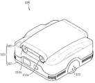
2 is a perspective view showing the appearance of the cleaning apparatus according to the present embodiment.
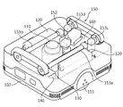
3 is a perspective view showing the inside of the cleaning apparatus according to the present embodiment.
4 is a perspective view showing a part of a driving unit of the cleaning apparatus according to the present embodiment.
5 is a plan view showing a part of a driving unit of the cleaning apparatus according to the present embodiment.
6 is a plan view showing the running operation of the cleaning apparatus according to the present embodiment.
The terms and words used in the present specification and claims should not be construed as limited to ordinary or dictionary terms and the inventor may appropriately define the concept of the term in order to best describe its invention It should be construed as meaning and concept consistent with the technical idea of the present invention. Therefore, the embodiments described in the present specification and the configurations shown in the drawings are only examples of the present invention, and are not intended to represent all of the technical ideas of the present invention, so that various equivalents and modifications may be made thereto .
1 is a side view showing a state in which the cleaning device according to the present embodiment is installed in a water tank.
Referring to FIG. 1, the
The
FIG. 2 is a perspective view showing the appearance of the cleaning apparatus according to the present embodiment, and FIG. 3 is a perspective view showing the inside of the cleaning apparatus according to the present embodiment.
Referring to FIG. 2, the
A plurality of
The
The
The
The
And a buoyancy regulator (not shown) for diving may be additionally disposed on the
On the other hand, the
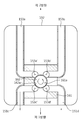
FIG. 4 is a perspective view showing a part of the steering unit of the cleaning apparatus according to the present embodiment, and FIG. 5 is a plan view showing a steering operation of the steering unit of the cleaning apparatus according to the present embodiment.
4 and 5, the
The
The
As the
In this way, the water sucked by the
6 is a plan view showing the running operation of the cleaning apparatus according to the present embodiment.
Referring to FIG. 6, the water sucked by the
For example, when the
According to the present invention, a driving force is obtained by a water jet spraying method using a suction force provided by the
If a separate power source is required to drive the cleaning device as in the conventional cleaning device, the internal battery must supply power to the driving wheel in addition to the pump. Therefore, the battery volume becomes large to operate wirelessly, There is a limit to providing a cleaning device that operates wirelessly. In the present invention, since the driving force is obtained from the water jet injection method and the internal battery can be used only for supplying power only to the pump, the weight of the cleaning device can be reduced. Therefore, the wireless interface can be used because the battery alone can provide sufficient operating time.
When the
Therefore, according to the present invention, it is possible to smoothly travel the
While the present invention has been particularly shown and described with reference to exemplary embodiments thereof, it will be understood by those skilled in the art that various changes and modifications may be made therein without departing from the spirit and scope of the invention. You will understand. Therefore, it is intended that the present invention covers all embodiments falling within the scope of the following claims, rather than being limited to the above-described embodiments.
10: Water tank 100: Cleaning device
110: Pump 120:
130: Sensor part 140: Battery
150: driving part 160: steering part
Claims (2)
A body portion;
A pump installed in the body and sucking water in the water tank;
A driving unit for driving the body by the pressure of the water sucked from the pump through the plurality of discharge tubes;
At least one of the plurality of discharge tubes is selected and the water is discharged through the selected discharge tube so that the progress direction of the body portion is adjusted And a steering unit for rotating the water tank.
Priority Applications (1)
| Application Number | Priority Date | Filing Date | Title |
|---|---|---|---|
| KR1020120118493A KR20140052413A (en) | 2012-10-24 | 2012-10-24 | Apparatus of cleaning bottom of water container |
Applications Claiming Priority (1)
| Application Number | Priority Date | Filing Date | Title |
|---|---|---|---|
| KR1020120118493A KR20140052413A (en) | 2012-10-24 | 2012-10-24 | Apparatus of cleaning bottom of water container |
Publications (1)
| Publication Number | Publication Date |
|---|---|
| KR20140052413A true KR20140052413A (en) | 2014-05-07 |
Family
ID=50885654
Family Applications (1)
| Application Number | Title | Priority Date | Filing Date |
|---|---|---|---|
| KR1020120118493A KR20140052413A (en) | 2012-10-24 | 2012-10-24 | Apparatus of cleaning bottom of water container |
Country Status (1)
| Country | Link |
|---|---|
| KR (1) | KR20140052413A (en) |
-
2012
- 2012-10-24 KR KR1020120118493A patent/KR20140052413A/en not_active Application Discontinuation
Similar Documents
| Publication | Publication Date | Title |
|---|---|---|
| US11939791B2 (en) | Controlling a movement of a pool cleaning robot | |
| ES2681694T3 (en) | Autonomous pool cleaning robot | |
| US10407930B2 (en) | Automatic electric top bottom swimming pool cleaner with internal pumps | |
| US9308977B2 (en) | Surface-cleaning device and vehicle | |
| ES2910255T3 (en) | Self-cleaning pool cleaner | |
| US10851558B2 (en) | Autonomous alternating-suction robot for cleaning swimming pools | |
| CN103654630A (en) | Gas-liquid separation device and hard surface cleaner with same | |
| EP3249137A1 (en) | Pool cleaner with drive motor navigation capabilities | |
| KR20140052413A (en) | Apparatus of cleaning bottom of water container | |
| CN110254660B (en) | Ship bottom cleaning device | |
| JP6449112B2 (en) | Cleaning device | |
| US9951537B2 (en) | Top-bottom pool cleaner including a nose | |
| KR101223742B1 (en) | Apparatus of cleaning bottom of water container | |
| JP6205011B1 (en) | Floating float transfer device | |
| CN219218831U (en) | Building site water accumulation cleaning robot | |
| EP2393573B1 (en) | Filter cleaning device | |
| JP6410875B2 (en) | Oil recovery unit | |
| JP2012062641A (en) | Cooling device | |
| CN114197925A (en) | Autonomous alternating suction robot for cleaning swimming pools | |
| JP2012087571A (en) | Floating device |
Legal Events
| Date | Code | Title | Description |
|---|---|---|---|
| A201 | Request for examination | ||
| E902 | Notification of reason for refusal | ||
| E601 | Decision to refuse application |