KR20140051825A - Assembly operating in a variable regime - Google Patents
Assembly operating in a variable regime Download PDFInfo
- Publication number
- KR20140051825A KR20140051825A KR1020137021635A KR20137021635A KR20140051825A KR 20140051825 A KR20140051825 A KR 20140051825A KR 1020137021635 A KR1020137021635 A KR 1020137021635A KR 20137021635 A KR20137021635 A KR 20137021635A KR 20140051825 A KR20140051825 A KR 20140051825A
- Authority
- KR
- South Korea
- Prior art keywords
- voltage
- alternator
- power
- output voltage
- rectifier
- Prior art date
Links
- 230000005284 excitation Effects 0.000 claims abstract description 20
- 230000001360 synchronised effect Effects 0.000 claims abstract description 19
- 230000001419 dependent effect Effects 0.000 claims abstract description 7
- XEEYBQQBJWHFJM-UHFFFAOYSA-N Iron Chemical compound [Fe] XEEYBQQBJWHFJM-UHFFFAOYSA-N 0.000 claims description 22
- 238000000034 method Methods 0.000 claims description 14
- 238000004804 winding Methods 0.000 claims description 12
- 230000000694 effects Effects 0.000 claims description 11
- 229910052742 iron Inorganic materials 0.000 claims description 11
- 230000001105 regulatory effect Effects 0.000 claims description 11
- 230000001276 controlling effect Effects 0.000 claims description 2
- 230000006870 function Effects 0.000 description 23
- 230000033228 biological regulation Effects 0.000 description 21
- 230000010363 phase shift Effects 0.000 description 10
- 230000008859 change Effects 0.000 description 9
- 238000005457 optimization Methods 0.000 description 7
- 230000000712 assembly Effects 0.000 description 5
- 238000000429 assembly Methods 0.000 description 5
- 238000004519 manufacturing process Methods 0.000 description 5
- 239000011159 matrix material Substances 0.000 description 5
- 238000006243 chemical reaction Methods 0.000 description 4
- 238000010586 diagram Methods 0.000 description 4
- 230000008901 benefit Effects 0.000 description 3
- 239000003990 capacitor Substances 0.000 description 3
- 238000006073 displacement reaction Methods 0.000 description 3
- 238000012546 transfer Methods 0.000 description 3
- 238000013459 approach Methods 0.000 description 2
- 230000002457 bidirectional effect Effects 0.000 description 2
- 238000004364 calculation method Methods 0.000 description 2
- 210000000078 claw Anatomy 0.000 description 2
- 230000008878 coupling Effects 0.000 description 2
- 238000010168 coupling process Methods 0.000 description 2
- 238000005859 coupling reaction Methods 0.000 description 2
- 230000007423 decrease Effects 0.000 description 2
- 238000013507 mapping Methods 0.000 description 2
- 238000012986 modification Methods 0.000 description 2
- 230000004048 modification Effects 0.000 description 2
- 238000012360 testing method Methods 0.000 description 2
- 230000000295 complement effect Effects 0.000 description 1
- 238000012937 correction Methods 0.000 description 1
- 238000013016 damping Methods 0.000 description 1
- 230000004907 flux Effects 0.000 description 1
- ZZUFCTLCJUWOSV-UHFFFAOYSA-N furosemide Chemical compound C1=C(Cl)C(S(=O)(=O)N)=CC(C(O)=O)=C1NCC1=CC=CO1 ZZUFCTLCJUWOSV-UHFFFAOYSA-N 0.000 description 1
- 230000006872 improvement Effects 0.000 description 1
- 238000011835 investigation Methods 0.000 description 1
- 238000012423 maintenance Methods 0.000 description 1
- 238000005259 measurement Methods 0.000 description 1
- 238000011160 research Methods 0.000 description 1
- 230000004044 response Effects 0.000 description 1
- 239000000523 sample Substances 0.000 description 1
- 238000005070 sampling Methods 0.000 description 1
- 230000009897 systematic effect Effects 0.000 description 1
Images


Classifications
-
- H—ELECTRICITY
- H02—GENERATION; CONVERSION OR DISTRIBUTION OF ELECTRIC POWER
- H02P—CONTROL OR REGULATION OF ELECTRIC MOTORS, ELECTRIC GENERATORS OR DYNAMO-ELECTRIC CONVERTERS; CONTROLLING TRANSFORMERS, REACTORS OR CHOKE COILS
- H02P9/00—Arrangements for controlling electric generators for the purpose of obtaining a desired output
- H02P9/14—Arrangements for controlling electric generators for the purpose of obtaining a desired output by variation of field
-
- F—MECHANICAL ENGINEERING; LIGHTING; HEATING; WEAPONS; BLASTING
- F03—MACHINES OR ENGINES FOR LIQUIDS; WIND, SPRING, OR WEIGHT MOTORS; PRODUCING MECHANICAL POWER OR A REACTIVE PROPULSIVE THRUST, NOT OTHERWISE PROVIDED FOR
- F03D—WIND MOTORS
- F03D7/00—Controlling wind motors
- F03D7/02—Controlling wind motors the wind motors having rotation axis substantially parallel to the air flow entering the rotor
- F03D7/04—Automatic control; Regulation
-
- H—ELECTRICITY
- H02—GENERATION; CONVERSION OR DISTRIBUTION OF ELECTRIC POWER
- H02K—DYNAMO-ELECTRIC MACHINES
- H02K19/00—Synchronous motors or generators
- H02K19/16—Synchronous generators
- H02K19/26—Synchronous generators characterised by the arrangement of exciting windings
- H02K19/28—Synchronous generators characterised by the arrangement of exciting windings for self-excitation
-
- H—ELECTRICITY
- H02—GENERATION; CONVERSION OR DISTRIBUTION OF ELECTRIC POWER
- H02P—CONTROL OR REGULATION OF ELECTRIC MOTORS, ELECTRIC GENERATORS OR DYNAMO-ELECTRIC CONVERTERS; CONTROLLING TRANSFORMERS, REACTORS OR CHOKE COILS
- H02P9/00—Arrangements for controlling electric generators for the purpose of obtaining a desired output
- H02P9/08—Control of generator circuit during starting or stopping of driving means, e.g. for initiating excitation
-
- H—ELECTRICITY
- H02—GENERATION; CONVERSION OR DISTRIBUTION OF ELECTRIC POWER
- H02P—CONTROL OR REGULATION OF ELECTRIC MOTORS, ELECTRIC GENERATORS OR DYNAMO-ELECTRIC CONVERTERS; CONTROLLING TRANSFORMERS, REACTORS OR CHOKE COILS
- H02P9/00—Arrangements for controlling electric generators for the purpose of obtaining a desired output
- H02P9/14—Arrangements for controlling electric generators for the purpose of obtaining a desired output by variation of field
- H02P9/26—Arrangements for controlling electric generators for the purpose of obtaining a desired output by variation of field using discharge tubes or semiconductor devices
- H02P9/30—Arrangements for controlling electric generators for the purpose of obtaining a desired output by variation of field using discharge tubes or semiconductor devices using semiconductor devices
- H02P9/305—Arrangements for controlling electric generators for the purpose of obtaining a desired output by variation of field using discharge tubes or semiconductor devices using semiconductor devices controlling voltage
-
- H—ELECTRICITY
- H02—GENERATION; CONVERSION OR DISTRIBUTION OF ELECTRIC POWER
- H02P—CONTROL OR REGULATION OF ELECTRIC MOTORS, ELECTRIC GENERATORS OR DYNAMO-ELECTRIC CONVERTERS; CONTROLLING TRANSFORMERS, REACTORS OR CHOKE COILS
- H02P9/00—Arrangements for controlling electric generators for the purpose of obtaining a desired output
- H02P9/48—Arrangements for obtaining a constant output value at varying speed of the generator, e.g. on vehicle
-
- H—ELECTRICITY
- H02—GENERATION; CONVERSION OR DISTRIBUTION OF ELECTRIC POWER
- H02K—DYNAMO-ELECTRIC MACHINES
- H02K7/00—Arrangements for handling mechanical energy structurally associated with dynamo-electric machines, e.g. structural association with mechanical driving motors or auxiliary dynamo-electric machines
- H02K7/18—Structural association of electric generators with mechanical driving motors, e.g. with turbines
- H02K7/1807—Rotary generators
- H02K7/1823—Rotary generators structurally associated with turbines or similar engines
- H02K7/183—Rotary generators structurally associated with turbines or similar engines wherein the turbine is a wind turbine
- H02K7/1838—Generators mounted in a nacelle or similar structure of a horizontal axis wind turbine
-
- Y—GENERAL TAGGING OF NEW TECHNOLOGICAL DEVELOPMENTS; GENERAL TAGGING OF CROSS-SECTIONAL TECHNOLOGIES SPANNING OVER SEVERAL SECTIONS OF THE IPC; TECHNICAL SUBJECTS COVERED BY FORMER USPC CROSS-REFERENCE ART COLLECTIONS [XRACs] AND DIGESTS
- Y02—TECHNOLOGIES OR APPLICATIONS FOR MITIGATION OR ADAPTATION AGAINST CLIMATE CHANGE
- Y02E—REDUCTION OF GREENHOUSE GAS [GHG] EMISSIONS, RELATED TO ENERGY GENERATION, TRANSMISSION OR DISTRIBUTION
- Y02E10/00—Energy generation through renewable energy sources
- Y02E10/70—Wind energy
- Y02E10/72—Wind turbines with rotation axis in wind direction
Abstract
본 발명은 다양한 상황, 특히 다양한 속도, 전력 또는 역률에 따라 동작하는 전기기계 어셈블리로서, 전력이 1MW 이상이고, 권선형 로터를 가지며, 특히 익사이터 또는 스프릿 링과 커뮤테이터에 의한 직접 익사이테이션에 의한, 전압을 통해 DC 전류를 제공받고, 출력 전압을 전달하는 동기식 알터네이터; 및 상기 알터네이터의 출력 전압을 정류하는 정류기를 포함하고, 상기 정류기는 펄스폭 변조 또는 다이오드기반이고, 선택적으로 DC/DC 컨버터가 수반되는 컨버터를 포함하고, 공급 전압은 상기 알터네이터의 출력 전압에 종속되는 권선형 로터에 전력을 공급한다.The present invention relates to an electromechanical assembly operating according to various situations, in particular with varying speeds, powers or power factors, having a power of at least 1 MW and having a wire-wound rotor, in particular by direct excitation by an exciter or split ring and a commutator A synchronous alternator receiving the DC current through the voltage and delivering the output voltage; And a rectifier for rectifying the output voltage of the alternator, wherein the rectifier is a pulse-width-modulated or diode-based, optionally a DC / DC converter, and the supply voltage is dependent on the output voltage of the alternator And supplies electric power to the wound rotor.
Description
본 발명은 단상 또는 다상, 예를 들어 삼상, AC 전류의 생산에 관한 것으로서, 보다 상세하게는 예를 들어 풍력 터빈(wind turbine)에 의해 얻어지는 기계적 에너지의 전기적 에너지로의 전환에 관한 것이다.The present invention relates to the production of single-phase or multiphase, for example three-phase, AC currents, and more particularly to the conversion of mechanical energy obtained by, for example, a wind turbine into electrical energy.
그래서 본 발명은 알터네이터, 특히 고전력의, 일반적으로는 1MW보다 크거나 같고, 예를 들어 풍력 터빈에 의한 회전에 의해 구동되는 로터를 포함하는 알터네이터 및 컨버터를 포함하는 전기기계 어셈블리에 관한 것으로서, 더욱 구체적으로는 권선형 로터 동기식 알터네이터(wound rotor synchronous alternators)에 관한 것이다. 이러한 구동은 조력구동, 수력 또는 해류 구동 발전기에 의해 대체할 수 있다.The present invention therefore relates to an electromechanical assembly comprising an alternator, and in particular an alternator and a converter comprising a rotor of high power, generally greater than or equal to 1 MW, driven by rotation, for example by a wind turbine, To wound rotor synchronous alternators. ≪ RTI ID = 0.0 > [0002] < / RTI > Such a drive may be replaced by a tidal, hydro or ocean current generator.
알터네이터는, 일반적으로 로터에 어느 정도 그 자체로 알려진 필드 와인딩(field winding)을 포함하고, 일반적으로 스테이터(stator)에 있는, 아마추어 와인딩(armature winding)에서, AC 전압을 발생시키기 위해 스프릿 링(split rings)과 브러시(brushes)에 의하거나, 익사이터(exciter)에 의해 DC 전류를 공급받는다.The alternator includes a field winding, which is generally known per se to the rotor, and is generally a stator, in an armature winding, for generating an AC voltage, rings and brushes, or are supplied with a DC current by an exciter.
알터네이터로서 케이지 타입(cage-type)의 비동기식 기계를 사용하는 것이 알려져 있는데, 이러한 케이지 타입의 비동기식 기계는 간소함과 견고함의 이점이 있다. 그러나, 거의 고정된 속도에서 그것의 동작은 슬리피지(slippage) 내에서 블레이드의 방향의 반복된 수정에 의한 노이즈의 원천일 수 있고, 이는 샤프트상의 기계적인 토크의 변화를 일으킬 수 있다. 커런트 드로운(current drawn)은 중요한 변화를 겪을 수 있기 때문에, 이러한 토크 변화는 네트워크에 방해를 야기할 수 있다. 뿐만 아니라, 이론적인 전력의 최대값은 높은 풍속에는 이용될 수 없다.It is known to use cage-type asynchronous machines as alternators, and these cage-type asynchronous machines have the advantage of simplicity and robustness. However, at an almost fixed speed its operation can be the source of noise due to repeated modifications of the direction of the blade in the slippage, which can cause a change in the mechanical torque on the shaft. Since current drawn can undergo significant changes, this torque change can cause interference to the network. In addition, the theoretical maximum power can not be used for high wind speeds.
전력전자 인터페이스를 통해 네트워크에 연결된 케이지 타입의 비동기식 기계로 만들어지는 이용(use)의 경우에, 다양한 속도의 구동에 의해 다양한 속도 동작이 가능하다. 정류기(rectifier)의 존재는 DC 전압을 전달하는 것을 가능하게 하고 인버터는 이러한 네트워크에 대응하는 단위 역률을 갖는 고정된 주파수의 AC 전압을 전달하는 것을 가능하게 한다. 그러면 알터네이터의 정격 전력은 풍력 터빈에 의해 제공될 수 있는 최대 전력을 결정한다. 그러나, 사용된 컨버터는 알터네이터와 네트워크 사이에 교환된 전력의 전체에 따라 평가된다. 그러므로 그들은 중요한 비용을 나타내고, 무시할 수 없는 로스를 가지며, 전달된 에너지의 효율성과 품질에 해로운 방해를 일으킬 수 있다. 제네레이터(generator)의 정격 전력의 전체로 어쩔 수 없이 정격 초과되는(over-rated) 이러한 컨버터의 사용은, 예를 들어 정격전압의 3%까지의 손실을 일으킬 수 있다.In the case of a use made of a cage type asynchronous machine connected to the network through a power electronic interface, various speed operations are possible by driving at various speeds. The presence of a rectifier makes it possible to deliver a DC voltage and the inverter makes it possible to deliver a fixed frequency AC voltage with a unit power factor corresponding to this network. The rated power of the alternator then determines the maximum power that can be provided by the wind turbine. However, the converter used is evaluated according to the total power exchanged between the alternator and the network. They therefore represent significant costs, have negligible losses, and can cause harmful interference to the efficiency and quality of the delivered energy. The use of such a converter inevitably over-rated as a whole of the generator's rated power can cause, for example, up to 3% of the rated voltage to be lost.
사용되는 정류기는 펄스폭 변조(pulse width modulation: PWM)에 의해 제어되는 정류기일 수 있다. 이러한 경우, 무효 전력(reactive power)의 전달은 제어가능할 수 있으나, 다이오드 브리지를 포함하는 단순한 정류기가 사용될 때에는 유효전력(active power)의 전달은 동일하게 유지된다.The rectifier used can be a rectifier controlled by pulse width modulation (PWM). In this case, the transfer of reactive power may be controllable, but the transfer of active power remains the same when a simple rectifier including a diode bridge is used.
이중 여자 비동기식 기계(doubly fed asynchronous machine)가 사용되는 경우, 전력전자 인터페이스가 로터와 네트워크 사이에 삽입되는 동안 스테이터는 네트워크에 직접 연결되어서 슬리피지(slippage)와 이로 인한 대략 30%의 회전속도의 변화 범위를 허용한다. 그러나, 이것은 케이지 타입의 비동기식 기계보다 더 복잡한 구조를 갖고 있어 더 비싸며 더 낮은 신뢰도를 갖는 기계이다. 네트워크에 직접적으로 연결된 기계의 스테이터, 또한 그것은 네트워크 방해가 있는 동안 전류에 있어서 큰 변화를 겪을 수 있다.When a doubly fed asynchronous machine is used, the stator is connected directly to the network, while the power electronic interface is inserted between the rotor and the network, resulting in a slippage and hence a change in rotational speed of about 30% Allow range. However, this is a more expensive and less reliable machine having a more complex structure than a cage type asynchronous machine. The stator of the machine, which is directly connected to the network, can also undergo a significant change in current while there is network interruption.
또한 그것은 특히, 영구 자석(permanent magnet)을 포함하는, 동기식 기계를 사용하는 것으로 알려져 있다. 특히, 영구 자석 알터네이터의 사용은 풍력 에너지의 전환으로 알려진 인버터가 수반된 정류기(rectifier)를 포함할 수 있는 전력전자 인터페이스가 수반된다. 회전 속도의 변화의 범위는 통상적으로 정격 회전 속도의 30%에서 120%이다. 그러나, 이러한 알터네이터는 불량의 경우, 예를 들어 단락(short circuit)이나 과속(overspeed)의 경우, 기계를 디-익사이트(de-excite) 하는 것의 불가능성뿐만 아니라, 특히 영구자석의 존재로 인해 중요한 비용의 결점을 드러낸다.It is also known to use synchronous machines, especially including permanent magnets. In particular, the use of a permanent magnet alternator is accompanied by a power electronics interface, which may include a rectifier accompanied by an inverter known as the conversion of wind energy. The range of variation of the rotational speed is typically 30% to 120% of the rated rotational speed. However, such an alternator is not only important because of the impossibility of de-exciting the machine in the event of a fault, for example in case of short circuit or overspeed, but also because of the presence of permanent magnets, Exposes the shortcomings of cost.
또한 로터에서 네트워크로부터 인버터가 수반된 정류기를 포함할 수 있는 전력전자 인터페이스를 통해 끌어낸 와인딩에 의해 익사이티드된(excited) 동기식 기계를 사용하는 것은 알려져 있다. 변화의 범위는 마그넷 타입 기계를 위한 것과 같은 자릿수(order of magnitude)를 갖는다.It is also known in the rotor to use a synchronous machine that is excited by a pulled-up winding through a power electronics interface that may include a rectifier with an inverter from the network from the network. The range of change has the same order of magnitude as for a magnet type machine.
EP 1 187 307 A2 출원은 컨버터에 공급하는, 클로 폴 로터(claw pole rotor)를 포함하는 전기 기계를 개시한다. 클로 폴 로터는 작은 사이즈와 저전력의 전기 기계의 특징이 있다.
US 5 083 039 A 특허는 비동기식 케이지 기계 및 토크 또는 전압을 제어하기 위하여 파라미터 id와 iq에 대한 레귤레이션 동작(regulation act)을 개시한다.US 5 083 039 A discloses an asynchronous cage machine and a regulation act for parameters i d and i q to control torque or voltage.
US 6 239 996 B1 특허는 자동차 배터리를 충전하기 위한 기계에 관한 것이다 The patent US 6 239 996 B1 relates to a machine for charging an automotive battery
US 6 437 996 B1 특허는 여러 킬로미터를 넘어 최소 손실로 에너지를 전송하기 위해 무효 전력을 감소시키도록 일정한 DC 전압으로 스위칭하는 것을 목적으로 한다.The patent US 6 437 996 B1 aims at switching to a constant DC voltage to reduce the reactive power in order to transmit energy with a minimum loss over several kilometers.
그러므로 감소된 규모와 감소된 제조 비용을 갖는 풍력 에너지 전환 어셈블리를 이용하기 위한 요구가 존재한다.Therefore, there is a need to utilize wind energy conversion assemblies with reduced scale and reduced manufacturing costs.
또한 얻어진 효율성을 최적화하는 것을 가능하게 하는 어셈블리로부터 이익을 얻기 위한 요구가 존재한다 There is also a need to gain from assemblies that make it possible to optimize the efficiency achieved
본 발명은 모든 또는 일부의 전술한 요구들을 만족하게 하는 것을 목적으로 한다.The present invention is directed to satisfying all or some of the foregoing needs.
따라서, 본 발명의 대상은, 일 측면에 따르면, 다양한 상황(regime), 특히 다양한 속도, 전력 또는 역률에서 동작하는 전기기계 어셈블리로서, 다음을 포함한다:Accordingly, an object of the present invention is, according to one aspect, an electromechanical assembly operating in various regimes, especially at various speeds, powers or power factors, including:
- 권선형 로터를 갖고, 특히 익사이터(exciter) 또는 스프릿 링(split ring)과 커뮤테이터(commutator)에 의한 직접 익사이테이션(excitation)에 의한, 전압(Vf)을 통해 DC 전류를 제공받고, 출력 전압(Us)을 전달하는 동기식 알터네이터,- having a winding rotor and being provided with a DC current through a voltage (V f ), in particular by direct excitation by an exciter or a split ring and a commutator, A synchronous alternator for transferring the output voltage U s ,
- 알터네이터의 출력 전압(Us)을 정류하는(for rectifying) 정류기를 포함하되, 상기 정류기는, 가능한(possibly), 펄스폭 변조 또는 다이오드 기반(diode-based)이고, 선택적으로 DC/DC 컨버터가 수반되는 컨버터,A rectifier for rectifying the output voltage U s of the alternator, possibly, possibly pulse-width-modulated or diode-based, and optionally a DC / DC converter Accompanying converters,
상기 공급 전압(Vf)은, 알터네이터의 출력전압(Us)에 종속되는 권선형 로터에 전력을 공급한다.The supply voltage (V f ) supplies power to a wire-wound rotor that depends on the output voltage (U s ) of the alternator.
상기 어셈블리는 미리 정해진 값(Us eff ref)에서 알터네이터의 출력전압(Us)을 유지하기 위해 상기 전압(Vf)에서 작동하도록 설정된 레귤레이터를 포함할 수 있다. 권선형 로터에 전력을 공급하는 상기 공급 전압(Vf)은 알터네이터의 출력전압(Us)과 기준 전압(Us eff ref)과의 차이를 최소화하도록 결정될 수 있다.The assembly has a predetermined value U s eff ref to operate at the voltage (V f ) to maintain the output voltage (U s ) of the alternator. The supply voltage (V f ) for supplying power to the wound rotor is determined by the output voltage (U s ) of the alternator and the reference voltage (U s eff lt; / RTI > ref ).
상기 기준전압(Us eff ref)은 전기기계 어셈블리의 효율성을 수정, 특히 최대화하기 위해 선택될 수 있다. The reference voltage U s eff ref ) may be selected to modify, in particular maximize, the efficiency of the electromechanical assembly.
바람직하게는, 상기 기준전압(Us eff ref)은 다음의 목록으로부터 적어도 하나의 로스를 최소화하기 위해 산출될 수 있다: 아이언 로스, 맴돌이 전류에 의한 로스, 히스테리시스에 의한 로스, 로터에서 줄효과를 통한 로스, 스테이터에서 줄 효과를 통한 로스, 컨버터에서 전도에 의한 로스, 컨버터에서 스위칭에 의한 로스.Preferably, the reference voltage U s eff ref ) can be calculated to minimize at least one loss from the following list: iron loss, eddy current loss, hysteresis loss, loss through rotor effect by rotor, loss by streak effect by stator, Loss by conduction in converter, loss by switching in converter.
상수(U/f)를 가진 레귤레이션의 경우 주파수의 함수로서 전압(Us)의 변화는 직선이다. 본 발명에서 주파수의 함수로서 출력 전압(Us)의 변화는 직선이 아닐 수 있고, 알터네이터의 전력이 상당히 증가하는 경향이 있는, 최소 회전 속도(예를 들어 분당 500회전 이상)부터 정격 속도(예를 들어 분당 1500회전 이상)까지 이르는 회전 속도 범위 이상에서 특히, (U/f)는 상수가 아니다. 이 속도의 범위(예를 들어 분당 500-1500회전)를 넘어서면, 주파수의 함수인 알터네이터의 출력전압의 형태는 회전 속도를 갖는 하나의 조각으로부터 다른 것까지 조금씩 증가하는 경사를 갖는 직선 조각들의 연속일 수 있다.In the case of regulation with a constant (U / f), the change in voltage (U s ) as a function of frequency is a straight line. The variation of the output voltage U s as a function of frequency in the present invention may not be a straight line and may vary from a minimum rotational speed (e.g., greater than 500 revolutions per minute) to a rated speed (U / f) is not a constant above the range of rotational speeds up to and including 1500 revolutions per minute. Beyond this range of speeds (for example, 500-1500 revolutions per minute), the form of the alternator's output voltage, which is a function of frequency, is a series of straight segments with a slope that gradually increases from one slice to another Lt; / RTI >
출력 전압의 변화를 제공하고, 그러므로 주파수의 함수로서 전압 세트포인트의 변화를 제공하는 곡선은, 여기서 전압이 상수로 유지되는 플래토(plateau)를 연결하는 표시된 킹크(kink)에 의해 연결되는 두 부분을 표시할 수 있다. 또한 여기서 U/f가 최대값(U)까지 상수인 종래의 레귤레이션(regulation)은 U가 상수로 유지되는 경우, 플래토를 표시하지만, 킹크(kink)는 없다.The curve providing a variation of the output voltage and thus providing a variation of the voltage set point as a function of frequency is shown here as a two part connected by a marked kink connecting the plateau where the voltage is held constant Can be displayed. Also, the conventional regulation where U / f is a constant up to the maximum value (U) shows the plateau when U is kept constant, but there is no kink.
본 발명에 따른 레귤레이션으로, Us는 상수 U/f를 가지고, 특정 회전 속도까지 레귤레이션에서 통상적으로 접하는 전압보다 적을 수 있고, 그러면 여기서 전압은 최대값이 된다.With the regulation according to the invention, U s has a constant U / f, which may be less than the voltage normally tangential in regulation up to a certain rotational speed, where the voltage is at its maximum.
바람직하게는, 최적화된 상황(regime)에서 조직적으로 동작하는 것이 추구되고, 다시 말해 주어진 동작 상황(regime)을 위해, 다시 말해 주어진 풍속에서, 최대 전력이 제공되는 것이 요구된다. 본 발명에 따른 알터네이터는 다양한 주파수에서 전기에너지를 제공하는 것을 가능하게 하는데, 그것은 네트워크에 적응되어야 하고, 이것은 전력 컨버터를 통해 얻어지고, 인버터뿐만 아니라 정류기를 포함하며, DC 버스를 경유하여 연결된다.Preferably, it is desired to operate systematically in an optimized regime, that is to say, for a given regime, i. E. At a given wind speed, a maximum power is required. The alternator according to the present invention makes it possible to provide electrical energy at various frequencies, which must be adapted to the network, which is obtained via a power converter, including the rectifier as well as the inverter, and is connected via a DC bus.
너무 높은 풍속에서는, 풍력 터빈의 회전속도는 그것의 온전함을 보호하기 위한 최대값으로 제한된다At too high wind speed, the rotational speed of the wind turbine is limited to the maximum value to protect its integrity
일정한(constant) 전압에서 동작하는 영구 자석 동기식 기계 또는 권선형 로터 동기식 기계와 비교할 때, 얻어지는 컨버터/기계 어셈블리의 전체적 효율이 개선된다.The overall efficiency of the resulting converter / machine assembly is improved when compared to a permanent magnet synchronous machine or a wire wound rotor synchronous machine operating at a constant voltage.
기준전압(Us eff ref)은 어셈블리의 동작 상황(regime)에 의존할 수 있다. 기준 전압(Us eff ref)은 속도, 전력, 역률 및 기계의 열적 상태 중 적어도 하나에 의존하는데, 그것은 예를 들어 열탐침기(thermal probe)에 의해 알려질 수 있다.The reference voltage U s eff ref ) may depend on the operating regime of the assembly. The reference voltage U s eff ref ) depends on at least one of speed, power, power factor, and thermal state of the machine, which may be known, for example, by a thermal probe.
“역률”이라는 표현은 전기적 리시버의 특성을 의미하는 것으로 이해되고, 그것은, 시변 전류 상황(정현파 또는 그와 다른 것)하에서 전력 공급받는 전기 다이폴을 위한 것이고, 이러한 다이폴에 의해 소비되는 유효전력을, 전류와 전압의 유효값의 곱(피상 전력: apparent power)으로 나눈 것과 동일한 것이다. 그것은 항상 0과 1사이에 있다. 특히, 만약에 전류와 전압이 시간의 사인함수라면, 역률은 전류와 전압 사이의 위상변화의 코사인값과 같다. 즉 역률은 일반적으로 "cosφ" 로 불린다.The expression " power factor " is understood to mean the characteristic of an electrical receiver, which is for electrical dipoles that are powered under time-varying current conditions (sinusoidal or otherwise), and the effective power consumed by such dipoles, Which is equal to the product of the current and the effective value of the voltage (apparent power). It is always between 0 and 1. In particular, if the current and voltage are sine functions of time, then the power factor is equal to the cosine of the phase change between the current and the voltage. That is, the power factor is generally referred to as "cos? &Quot;.
주어진 동작 상황에서, 다시 말해 주어진 속도와 주어진 전력에서, 기계적인 로스는 고정된다.In a given operating situation, that is to say at a given speed and given power, the mechanical losses are fixed.
주어진 동작 상황에서, 만약 전압이 너무 높으면, 너무 큰 익사이테이션(excitation) 때문에 아이언 로스(iron losses)와 로터에서의 줄효과(Joule effect)를 통한 로스가 중요하게 된다. 반대로, 스테이터(stator)에서는 줄효과를 통한 로스가 낮게 유지된다. 실제로, 주어진 전력에서, 만약 전압이 높으면, 전류는 낮다. 반대로, 너무 낮은 전압은 스테이터에서의 줄효과를 통한 심각한 로스와 스테이터에서의 아이언 로스와 로터에서의 줄효과를 통한 낮은 로스를 야기한다. 컨버터의 로스는 스테이터 전류, 기계 전압 및 정류된 전압(recified voltage)과 관련이 있다.Under given operating conditions, if the voltage is too high, loss due to the iron losses and the joule effect in the rotor becomes important due to too large excitation. Conversely, in the stator, the loss due to the streak effect is kept low. In fact, at a given power, if the voltage is high, the current is low. Conversely, too low a voltage causes a serious loss through the streak effect on the stator and a low loss through the iron effect on the stator and the streak effect on the rotor. The loss of the converter is related to the stator current, the machine voltage and the reclaimed voltage.
어셈블리의 로스를 최소화하고 효율을 최대화하는 것을 가능하게 하는 두 동작 상황(regime) 사이에 최적의 전압이 존재한다고 이해된다. 이 최적의 전압은 바람직하게는 기준 전압으로 선택되고 각 어플리케이션(application)에 의해 산출될 수 있다.It is understood that there is an optimal voltage between the two operating regimes that allows to minimize the loss of the assembly and to maximize efficiency. This optimum voltage is preferably selected as the reference voltage and can be calculated by each application.
그것은 어셈블리의 동작에 앞서 산출되거나 실시간으로 산출될 수 있다. 그것은 어셈블리의 동작 동안 실시간으로 산출되거나, 또는 다른 어플리케이션의 함수로 미리 산출될 수 있다. 예를 들어 어플리케이션 및/또는 동작 상황, 특히, 로터의 회전 속도의 함수로서 여러 개의 미리 저장된 값 중에서 기준 전압(Us eff ref)의 값을 선택하는 것이 가능하다. 예를 들어 어셈블리는 각각의 주어진 동작 상황에 각각 적합한 여러 개의 기준전압(Us eff ref)의 미리 저장된 값의 미리 저장된 테이블을 포함할 수 있다. 자동적으로, 하나의 동작 상황으로부터 다른 것으로 스위칭하는 것은 기준 전압을 변경하는 것을 수반한다.It can be calculated prior to the operation of the assembly or can be calculated in real time. It can be computed in real time during operation of the assembly, or can be calculated in advance as a function of another application. For example, among a plurality of pre-stored values as a function of the application and / or operating conditions, in particular the rotational speed of the rotor, the reference voltage U s eff ref ) can be selected. For example, the assembly may include a plurality of reference voltages U s eff ref ) stored in advance. Automatically switching from one operating state to another involves changing the reference voltage.
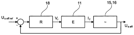
알터네이터가 익사이터(exciter)를 포함하는 경우, 전압(Vr)은 알터네이터에 의해 제공되는 유효출력전압(Us eff)에 종속되는 익사이터에서 필요한 익사이테이션(excitation)을 발생하는 것을 가능하게 한다.If the alternator comprises an exciter, the voltage V r is determined by the effective output voltage U s from the exciter that is dependent on eff) it makes it possible to generate a presentation iksayi (excitation) required.
변형예로서, 알터네이터의 권선형 로터의 익사이테이션(excitation)은 스프릿 링(split ring)과 커뮤테이터(commutator)에 의해, 다이렉트(direct)일 수 있다. 스프릿 링(split ring)과 브러시 시스템(brush system)에 의한 로터로의 전력 공급의 경우, 전압(Vr)은 미리 정해진 기준 전압(Us eff ref)에 근거하여 직접적으로 제어된다.As an alternative, the excitation of the wound rotor of the alternator may be direct, by means of a split ring and a commutator. In the case of power supply to the rotor by means of a split ring and brush system, the voltage V r is a predetermined reference voltage U s eff ref ). < / RTI >
어셈블리는 정류기(rectifier)의 전자 스위치를 제어하는 레귤레이터(regulator)를 포함할 수 있다.The assembly may include a regulator that controls the electronic switch of the rectifier.
정류기(rectifier)의 제어는 위상, 기계의 역률, 다이렉트 커런트(direct current)의 인텐시티(ID) 및 쿼드러쳐 커런트(quadrature current)의 인텐시티(IQ)에 종속될 수 있고, 이 모든 것은 정류기(rectifier)의 전자 스위치를 제어하는데 사용될 수 있다. 정류기(rectifier)의 출력전류는 DC 버스에 전력을 공급할 수 있다. 정류기(rectifier)는 일정한 버스 전압을 유지하기 위해 제어될 수 있다. 어셈블리는 이러한 목적의 레귤레이터를 포함할 수 있고, 그것은 DC 버스의 단자를 가로질러 측정된 전압(Udc measured)과 기준전압(Udc ref)의 함수로서 정류기의 스위치를 제어하는 레귤레이터의 전류 기준에 종속하는 것을 가능하게 한다. 이 전류 기준은 쿼드러쳐 및/또는 다이렉트 커런트의 인텐시티(intensity)의 기준값일 수 있다.The control of the rectifier may depend on the phase, the power factor of the machine, the intensity of the direct current I D , and the intensity of the quadrature current I Q , lt; / RTI > rectifier. The output current of the rectifier can power the DC bus. The rectifier can be controlled to maintain a constant bus voltage. The assembly may include a regulator for this purpose, which may include measuring the voltage across the terminals of the DC bus (U dc measured ) and the reference voltage U dc gt; ref < / RTI > of the regulator that controls the switch of the rectifier. This current reference may be a quadrature and / or direct current intensity reference value.
더욱이 본 발명의 대상은 제네레이터(generator), 특히 앞서 정의한 바와 같은 어셈블리를 포함하는 풍력 터빈이다.Moreover, the subject of the invention is a wind turbine including a generator, in particular an assembly as defined above.
풍력 터빈은 풍력 터빈의 블레이드, 예를 들어 3개의 블레이드,에 의한 회전으로 구동되는 어셈블리의 기계적 샤프트의 속도를 증가하는 것을 가능하게 하는 멀티플라이어(multiplier)를 포함할 수 있다.A wind turbine may include a multiplier that makes it possible to increase the speed of a mechanical shaft of an assembly driven by rotation of a blade of a wind turbine, for example, three blades.
더욱이 본 발명의 대상은, 특히 풍력 근원의, 기계적 에너지를, 특히 상기에서 정의된 바와 같은 어셈블리에 의한, 전기적 에너지로 변환하는 방법이고, 여기서 권선형 로터를 가진 동기식 알터네이터의 로터는 알터네이터의 출력 전압(Us)에 종속되는 전압(Vf)에서 DC 전류를 공급받는다. 특히 알터네이터의 출력 전압(Us)과 미리 정해진 기준 전압(Us eff ref) 사이의 차이를 최소화하는 것이 추구된다.Moreover, the object of the invention is a method for converting the mechanical energy of a wind source, in particular to an electrical energy, in particular by an assembly as defined above, wherein the rotor of the synchronous alternator with a wound rotor has an output voltage at a voltage (V f) that is dependent on (U s) it is supplied with a DC current. The output voltage U s of the alternator and the predetermined reference voltage U s eff ref ) is sought to be minimized.
펄스폭 변조 타입 정류기를 갖는 알터네이터의 출력전압 방법으로 정류(rectify)하는 것이 바람직할 수 있다.It may be desirable to rectify by the output voltage method of the alternator with a pulse width modulation type rectifier.
본 발명에 따른 전기기계 어셈블리는 영구 자석을 가진 알터네이터와 효율성의 면에서 동일한 이점을 제공하면서, 이러한 영구 자석의 존재에 관련된 결점이 없다. 본 발명에 따른 어셈블리는 실제로 어셈블리의 비용과 유지보수의 용이함을 개선시키는 것이 가능하다. 게다가, 본 발명에 따른 어셈블리는 영구 자석 알터네이터와 대비하여 쉽게 디-익사이트될(de-excited) 수 있다. The electromechanical assembly according to the present invention provides the same advantages in terms of efficiency as the alternator with permanent magnets, but without the drawbacks associated with the presence of such permanent magnets. The assembly according to the present invention is actually capable of improving the cost of assembly and the ease of maintenance. In addition, the assembly according to the present invention can be easily de-excited relative to the permanent magnet alternator.
본 발명은 권선형 로터의 단자를 가로지르는 전압을 조정함으로써 권선형 로터 알터네이터와 다양한 상황(regime)에서 동작하는 관련된 컨버터의 효율성을 최적화할 수 있다. 그래서 전압은 로터의 익사이테이션(excitation) 방법에 의해 제어될 수 있다.The present invention can optimize the efficiency of the associated converter operating in various regimes with the wound rotor alternator by adjusting the voltage across the terminals of the wound rotor. So that the voltage can be controlled by the excitation method of the rotor.
본 발명에 따른 어셈블리는 제조하는데 덜 비싸다. 게다가, 결함, 예를 들어 네트워크의 결함이 있는 경우, 익사이테이션 전압에서 작동하는 것이 가능한데, 이것은 영구 자석 알터네이터가 있는 경우에는 가능하지 않다. 본 발명에 따른 어셈블리는 전기 네트워크의 결점을 처리하는 것이 가능하고, 이것은 특정한 규제 요구 사항을 만족시키는 것을 가능하게 할 수 있다.The assembly according to the invention is less expensive to manufacture. Furthermore, if there is a fault, for example a network fault, it is possible to operate at the excitation voltage, which is not possible in the presence of a permanent magnet alternator. The assembly according to the invention is capable of handling faults in the electrical network, which can make it possible to meet certain regulatory requirements.
다양한 상황에서의 동작은 풍력 터빈에 의해 수집되는 에너지를 최적화하는 것을 가능하게 한다.Operation in various situations makes it possible to optimize the energy collected by the wind turbine.
본 발명은 본 발명의 바람직한 실시예와 첨부된 도면을 따르는 상세한 설명을 읽음으로써 보다 잘 이해될 수 있다:
도 1은 본 발명에 따라 구현된 풍력 터빈을 개략적인 방법으로 나타내고,
도 2는 도 1의 풍력 터빈의 동기식 알터네이터의 구성을 개략적인 방법으로 도시하고,
도 3은 알터네이터와 그와 관련된 컨버터의 동작을 개략적인 방법으로 나타내고,
도 4는 익사이터의 컨트롤 체인의 개략적인 모습이고,
도 4a는 레귤레이터(18)의 동작을 도시하는 블록도이고,
도 5는 다른 알려진 어셈블리와 비교된 본 발명에 따른 어셈블리의 효율성을 나타내고,
도 6 내지 15는 어떻게 본 발명에 따른 레귤레이션 또는 레귤레이션들이 모델링될 수 있는지를 개략적인 방법으로 나타내고,
도 16은 풍력 터빈을 위한 로드 커브(load curve)를 나타내고, 그리고 그 커브는 알터네이터의 출력전압을 속도의 함수로 제공하며,
도 17은 보다 자세한 방법으로 출력전압의 커브를 속도의 함수로 나타내고,
도 18은 알터네이터의 로터의 속도의 함수로 효율성을 나타낸다.BRIEF DESCRIPTION OF THE DRAWINGS The present invention may be better understood by reading the following detailed description of a preferred embodiment of the invention and the accompanying drawings,
Figure 1 shows a wind turbine implemented in accordance with the present invention in a schematic manner,
Fig. 2 shows the configuration of the synchronous alternator of the wind turbine of Fig. 1 in a schematic manner,
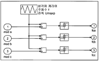
Figure 3 shows the operation of the alternator and its associated converter in a schematic way,
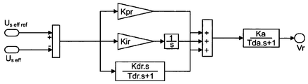
Figure 4 is a schematic view of the control chain of the exciter,
4A is a block diagram showing the operation of the
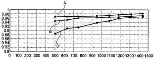
Figure 5 shows the efficiency of an assembly according to the invention compared to other known assemblies,
Figures 6 to 15 show in a schematic way how the regulation or regulation according to the invention can be modeled,
Figure 16 shows a load curve for a wind turbine, which curve provides the output voltage of the alternator as a function of speed,
Figure 17 shows the curve of the output voltage as a function of speed in more detail,
Figure 18 shows efficiency as a function of rotor speed of the alternator.
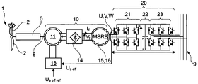
도 1에 도시된 것은 본 발명에 따른 풍력 터빈(1)인데, 이는 바람에 의한 회전으로 구동되도록 의도된, 고정된 블레이드(2), 예를 들어 3개의 블레이드에, 나셀(nacelle)을 포함한다. 나셀(nacelle)은 마스트(mast)의 상부에 고정되는데, 표시되지 않았다. 멀티플라이어(5)는 풍력 터빈의 기계적 샤프트(6)의 속도를 증가하는 것을 가능하게 한다 1 is a
나셀은 기계적인 샤프트(6)에 의해 받은 풍력 에너지를 전기 에너지로 컨버팅하고 네트워크(19)에 공급하는 컨버터(20)뿐만 아니라 동기식 알터네이터(10)를 수용한다. 알터네이터는 이 목적을 위해 출력 전압(Us eff)을, 예를 들어 3상 전압을 전달하는데, 3상은 통상적으로 U,V 및 W로 지정된다.The nacelle accommodates the
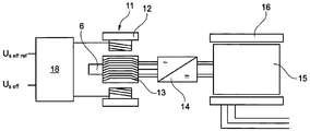
설명한 예에서, 알터네이터는 스테이터(12)에 익사이터 로터(13)의 익사이터 아마추어 와인딩(exciter armature winding)에서 AC 전류를 발생하기 위해 DC 전류를 공급받는 익사이터 필드 와인딩(exciter field winding)을 갖는 익사이터를 포함하고, 그 후 그것은 정류된 전류(IF)를 가진 알터네이터의 권선형 로터(15)의 메인 필드 와인딩을 공급하고 알터네이터의 스테이터(16)에 있는 메인 아마추어에서 전류를 생산하기 위해 정류기 브릿지(14)에 의해 정류된다. 메인 아마추어(main armature)의 각 상은 하나 또는 그 이상의 와인딩(winding)을 포함할 수 있다.In the illustrated example, the alternator has an exciter field winding supplied with a DC current to generate an AC current in the exciter armature winding of the
도 1 및 2에 도시된 바람직한 실시예는 반전된(inverted) 알터네이터로 이루어지는 동기식 익사이터(11)를 사용하고, 여기서 익사이테이션(excitation) 회로는 고정된 자기장을 발생시키기 위해, 스테이터(12) 상에 위치하고, 전압 레귤레이터(18)를 통한 전압(Vr)에서 DC 전류를 공급받는다. 익사이터(11)의 로터(13)는 메인 인덕터를 공급하기 위해 회전하는 다이오드 브리지 정류기(14)에 의해 전류가 정류된 3상 와인딩 시스템을 포함한다. 익사이터는 기계적 샤프트(6) 상에 장착되고 메인 로터(15)처럼 같은 속도에서 구동된다.The preferred embodiment shown in Figures 1 and 2 employs a
도시된 바람직한 실시예에서, 그리고 전력에 유념하면, 그것은 대략 몇 MWs 일 수 있고, 높은 전력 알터네이터일 수 있는데, 익사이테이션 전류(excitation current)를 제공하기 위해 샤프트(6)에 사용될 수 있는 기계적인 전력을 사용하는 것이 유리하다. 알터네이터의 로터로서 동일한 샤프트에 장착된 익사이테이션 시스템은 이와 같이 사용되었다. 그것은 변형예처럼 다를 수 있다.In the illustrated preferred embodiment, and with regard to power, it may be approximately a few MWs and may be a high power alternator, mechanical power that may be used for the
많은 수의 폴의 쌍(pairs of poles)을 포함하고, 그러므로 큰 직경인, 낮은 속도와 높은 토크의 동기식 알터네이터를 사용하는 것이 가능하다. 유리하게, 이와 같은 알터네이터는 속도 멀티플라이어를 사용하는 것을 피하는 것을 가능하게 한다. 이것은 로스와 결함을 제공할 수 있는 속도 멀티플라이어가 복잡한 기계적 아이템인 한 유리할 수 있다.It is possible to use a synchronous alternator of a large diameter, low speed and high torque, including a large number of pairs of poles. Advantageously, such an alternator makes it possible to avoid using a speed multiplier. This can be advantageous as the speed multiplier, which can provide loss and fault, is a complex mechanical item.
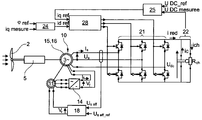
익사이터(11)의 것뿐만 아니라 컨버터(20)와 권선형 로터의 전력공급 전압의 레귤레이션은, 도 3을 참조하면서 상세하게 설명될 것이다.Regulation of the power supply voltage of the
컨버터(20)는 알터네이터에 의해 전달되는 AC 전압(Us eff)과 AC 전류(Is)를 DC 전압과 DC 전류로 변환하는 것을 가능하게 하는 펄스폭 변조(pulse width modulation: PWM) 타입의 정류기(21)를 포함한다.The
정류기(21)는 이러한 DC 전압과 이러한 DC 전류를 회복하는 인버터(23)에 커패시터(C)를 포함하는 DC버스(22)에 의해 연결된다. 인버터의 제어는 네트워크(9)에 적합한 진폭과 주파수를 가진 신호를 인버터의 출력에서 조절하고 얻기 위해 레귤레이트된다.The
본 발명에서, 펄스폭 변조 정류기(21)와 인버터(23)는 DC 버스(22)를 통해 서로 디커플(decouple)된다. DC 버스(22)를 통한 경로는 인버터(23)가 진폭과 주파수를 레귤레이트하는 것을 허용한다.In the present invention, the pulse
사용되는 정류기(21)는 전력에서 양방향성(bidirectionl)일 수 있다. 적절한 제어를 통해 높은 주파수에서의 고조파를 제거함으로써 정현파 전류를 얻는 것이 가능하다. 이러한 목적을 위해서, 전류는, 디커플링 알고리즘(29)과 함께 다이렉트 커런트(IDref)와 쿼드러처 커런트(IQref)의 기준 인텐시티의 함수로서, 알터네이터의 스테이터(16)의 전압과 전류 사이의 위상 변위(φ)를 제어하기 위해 정류기(21)의 스위치를 제어함으로써 28에서 레귤레이트되는데, 이는 가능한 대로 역률(cosφ)의 수정을 허용한다. 기준 위상변위(φref)와 측정된 쿼더러처 인텐시티(Iqmeasured)의 함수로서, 24에서 위상 변위의 레귤레이션(regulation)은 줄효과를 통한 스테이터 로스를 감소하는 것을 가능하게 하는데, 역률 1을 위해서 스테이터와 컨버터의 전도 줄 로스는 최소이다. 그래서 어셈블리의 전체적 능률은 만족스럽다.The
다양한 실시예에서 그리고 도시된 것처럼, 그것의 단자를 가로질러 측정된 전압(Udc measured)과 기준 전압(Udc ref)의 함수로서, 25에서 정류기(21)의 출력 전력을 레귤레이트하는 것이 가능한데, 그렇게 함으로써 전력의 더 나은 지역 제어를 허용한다.As in various embodiments and as shown, the voltage measured across its terminals, U dc measured ) and the reference voltage U dc ref ), it is possible to regulate the output power of the
레귤레이터의 예로, 시장에서 규격화된 레귤레이터를 사용하는 것이 가능하다. 인용될 수 있는 것 중에서: 리로이 소머 모델(Leroy Somer models), 예를 들어 D600, R449, the BASLER DECS 100, 200 모델, ABB Unitrol 100 모델 등.As an example of a regulator, it is possible to use a regulator that is standardized on the market. Among the cited ones are: Leroy Somer models, for example D600, R449, the
레귤레이팅 어셈블리(24,25 및 28)를 구현하기 위해, 전력 컨버터 모듈(전압 및/또는 cosφ 레귤레이션), 예를 들어 ABB ACS800 타입을 사용하는 것이 가능하다.To implement the
본 발명에 따른 레귤레이션의 예는 도 6 내지 15의 도움을 통해 자세한 방식으로 설명될 것이다.An example of regulation according to the present invention will be described in a detailed manner with the help of FIGS. 6-15.
자세히 기술한 예에서, 정류기(21)는 PWM타입이고 그것은 도 6에 나타난 것처럼 모델링될 수 있다. 자세히 기술된 예에서, 정류기(21)는 전력에서 양방향성(bidirectional)이다. 정류기의 적절한 제어는 알터네이터에서 높은 주파수에서 고조파를 제거함과 함께 정현파 전류를 얻는 것을 가능하게 할 수 있다.In the example described in detail, the
알터네이터의 스테이터의 전압과 전류 사이의 위상 변위(φ)의 제어가 수행될 수 있고, 기계의 역률(cosφ)의 수정을 허용한다.The control of the phase shift [phi] between the voltage and the current of the stator of the alternator can be performed, and the modification of the power factor (cos [phi] of the machine is allowed.
그래서 아이언 로스를 최소화하는 정현파를 얻는 것이 가능하다. 또한 위상 변위(φ)의 제어는 줄효과를 통한 로스에 영향을 주는 것을 가능하게 할 수 있는데, 이는 1과 동일한 cosφ에 대한 최소값이다.So it is possible to obtain a sinusoidal wave that minimizes the iron loss. Also, the control of the phase shift (φ) can make it possible to influence the loss through the jitter effect, which is the minimum for cos φ equal to 1.
그럼에도 불구하고, 이러한 제어는 전도와 컨버터의 스위칭에 의한 로스를 만족 값(satisfactory value)으로 감소시키는 것을 가능하지 못하게 할 수 있는데, 이는 정격 전력의 대략 1.5%가 남는다.Nevertheless, such control may make it impossible to reduce the loss due to conduction and switching of the converter to a satisfactory value, which is approximately 1.5% of the rated power.
정류기(21)는 DC 버스(22)의 전압(Udc)의 25에서 레귤레이션에 참여할 수 있는데, 이러한 레귤레이션은 인버터(23)의 정격 이상(over-rating)을 피하는 것이 가능할 수 있다.The
본 발명의 여기에서 자세히 기술된 바람직한 실시예에서, 정류기(21)의 구성요소(100)는 다음의 불 행위(Boolean behaviour)를 갖는 완벽한 스위치로 간주된다:In the preferred embodiment described in detail herein, the
- 0: 개방,- 0: open,
- 1: 단락.- 1: Paragraph.
정류기(21)의 기본 구조는 도 7에 나타난다.The basic structure of the
스위치는 이상적이고 전류에서 양방향인 것으로 고려된다.The switch is considered ideal and bi-directional in current.
정류기(21)의 구성을 나타내는 이 행렬은 다음과 같이 정의된다:This matrix representing the configuration of the

여기서, 도 7에 나타난 것처럼, T1, T2 및 T3은 각각 상보되는 것으로 스위치 T4, T5 및 T6를 갖는 3개의 스위치이다. 행렬 MC는 제어규칙의 함수로서 실시간으로 변화한다.Here, as shown in FIG. 7, T1, T2, and T3 are complementary to each other and are three switches having switches T4, T5, and T6. The matrix MC changes in real time as a function of the control rule.
DC 버스의 단자를 가로지르는 전압(Udc)이 안정하고, 인버터 컨벤션(convention)을 사용한 것에 의한다고 가정하면, m 포인트(전압 Udc의 접지)에 대한 각 위상의 기준 퍼텐셜 A, B, C는 Assuming that the voltage across the terminals of the DC bus (U dc ) is stable and is due to the use of an inverter convention, the reference potentials A, B, and C of each phase relative to m points (ground of voltage U dc ) The

이다.to be.
스타 커플링되고(being coupled as a star) 정류기(21)의 입력과 연결되는 알터네이터, 그것은 스테이터에서 메인 아마추어 와인딩(main armature winding)의 각 상의 단자를 가로지르는 퍼텐셜(potentials)을 산출하는 것이 가능하다. 따라서, 알터네이터의 스타 커플링(star coupling) 지점은 “n”에 의해 정의되고 각 상을 위한 동일한 임피던스와 안정된 전압이 고려된다.An alternator which is coupled as a star and connected to the input of the
상기의 조건과 함께, 아래의 방정식 세트를 세우는 것이 가능하다:Along with the above conditions, it is possible to establish the following equation set:

Vbn과 Vcn을 위해 동일한 방식에서 진행하면, 다음의 행렬 방정식이 얻어진다.Proceeding in the same way for V bn and V cn , the following matrix equation is obtained.

그러므로 Matlab-Simulink® 소프트웨어를 통해 모델링함으로써 도 8에 나타난 순간 크기에서 정류기 모델(21)은 다음과 같다:Thus, by modeling with Matlab-Simulink® software, the rectifier model (21) at the instantaneous magnitude shown in Figure 8 is as follows:

정류된 전류(irec)는 다음과 같이 된다.The rectified current i rec is given by:

도 9에 나타난 바와 같이, 알터네이터와 정류기(21)를 포함하는 전자기계 어셈블리가 R//C회로에 의해 로드된(loaded) 경우, DC 버스(22)의 작용(behaviour)이 지금 검토될 것이다.As shown in FIG. 9, when the electromechanical assembly comprising the alternator and
버스(22)의 전압(Udc)과 부하 전류(ild)는 다음의 방정식에 의해 관련된다.The voltage U dc of the

여기서 Tj(j=1,2,3)는 스위칭 함수이다.Here, Tj (j = 1, 2, 3) is a switching function.
자세히 기술된 예에서, 인버터와 네트워크를 대표하는 부하(R)는 3.15MW의 정격 전력 하에서 800V의 DC 전압(Udc)을 갖도록 선택된다.In the example described in detail, the load (R) representing the inverter and network is selected to have a DC voltage (U dc ) of 800V under a rated power of 3.15MW.
저항(R)은 부하 효과를 시뮬레이션하거나 시스템의 행동을 보기 위해 사용될 수 있다.The resistance (R) can be used to simulate load effects or to view system behavior.
버스의 전압(Udc)는 부하 전력 및 저항과 관련된다: 
자세히 기술된 예에서, R은 0.2(Ω)과 같게 선택된다.In the example described in detail, R is chosen equal to 0.2 (?).
자세히 기술된 예에서, 전압(Udc)은 800V(±5%)의 값으로 레귤레이트되어야 한다.In the example described in detail, the voltage U dc should be regulated to a value of 800V (± 5%).

DC 버스(22)의 커패시터(C)의 값은, 첫번째 근사(approximation)에서, 커패시터는 정격 부하 전류의 10%를 제공할 수 있어야 한다는 가정을 세움으로써 결정될 수 있다. 더욱이, DC버스(22)의 전압은, 자세히 기술된 예에서, 그것의 정격 값에 대하여 5%를 넘어서 변화해서는 안된다.The value of the capacitor C of the


그러므로 ![]()
![]()
전자기 어셈블리의 레귤레이션을 연구하기 위해, 안정 상태(steady state) 동작이 고려되고, 반면에 알터네이터의 스테이터 저항값은 무시한다.To study the regulation of electromagnetic assemblies, steady state operation is considered, while the stator resistance value of the alternator is ignored.
다음 방정식이 얻어질 수 있다:The following equation can be obtained:


그래서 기계의 유효전력은 쿼더러처 전류(IQ)에 의존한다.So the effective power of the machine depends on the quadrature current (I Q ).
정류기(21)의 효율성 이내에서, 기계의 유효전력은 DC버스(22)의 전력에 대응한다.Within the efficiency of the
마그넷 타입의 동기식 기계(magnet-type synchronous machine)의 경우, 다이렉트 커런트(ID)의 인텐시티와 쿼더러처 커런트(IQ)의 인텐시티의 레귤레이션을 수행하기 위한 자유도(degrees of freedom) 2가 가능하다.For magnet-type synchronous machines, degrees of
전류(IQ)는 DC버스(22)를 레귤레이트하는데 사용될 수 있고 전류(ID)는 알터네이터의 스테이터(16)의 전류와 전압 사이의 위상 변위(φ)를 레귤레이트하기 위해 사용될 수 있으며, 그렇게 함으로써 cosφ=1에서 동작 가능성을 제공한다.The current I Q can be used to regulate the
DQ평면에서 전류의 레귤레이션을 허용하기 위해, ID와 IQ축 차이의 커플링을 제거하는 것이 바람직하다. 이것은 도 10에 보여질 수 있는 것처럼, 디커플링 알고리즘(29)을 사용함으로써 수행될 수 있다.In order to allow regulation of the current in the DQ plane, it is desirable to eliminate the coupling of the I D and I Q axis differences. This can be done by using a decoupling algorithm 29, as can be seen in FIG.
이 디커플링 알고리즘에서 재분류의 목적은 D와 Q의 2개의 축을 따라 2개의 RL 회로를 제거하는 것인데 이는 사용되는 레귤레이터의 계산이 보다 간단하도록 하기 위해서이다. The purpose of reclassification in this decoupling algorithm is to remove two RL circuits along the two axes of D and Q in order to simplify the calculation of the regulator used.
두 축 사이에서 변수의 디커플링 이후, 다음의 행렬 방정식이 얻어진다.After decoupling the variables between the two axes, the following matrix equation is obtained.

그러면 전류와 관련된 방정식은 PI 콜렉터를 통해 레귤레이트될 수 있는 1차 시스템의 형태이다.The equation related to the current is then in the form of a primary system that can be regulated via the PI collector.
Vd와 Vq 신호는 스위치 DQ->abc를 허용하는 블록으로, 그리고 나서 정류기(21)의 스위치(100)의 제어를 만드는 단계로 보내진다.The V d and V q signals are sent to the block that allows the switch DQ-> abc and then to make control of the
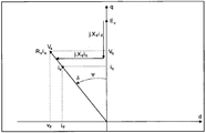
스테이터(16)의 전류와 전압 사이의 위상 변위(φ)의 레귤레이션의 테두리 안에서, 모터 컨벤션과 파크 참조 프레임에서의(in the Park reference frame with motor convention) 전압의 다이어그램은 도 11에 나타나 있다:A diagram of the motor convention and the voltage in the Park reference frame with motor convention is shown in FIG. 11, within the framework of regulation of the phase shift (?) Between the current and voltage of the stator 16:
![]()

![]()
따라서 
cosφ가 1과 같은 상태로 동작하는 것이 가능하다고 알려져 있다.it is known that it is possible to operate in a state where cos? is equal to 1.
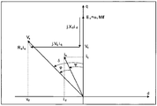
도 12는 cosφ가 1인 상태에서 모터 컨벤션과 파크 참조 프레임에서의(in the Park reference frame with motor convention) 전압 다이어그램을 나타낸다. 도 12에 나타난 방법은 단위 역률을 가지고 동작을 허용하는 내부 위상 변위각을 추정하는데 사용될 수 있다.12 shows a voltage diagram of the motor convention and the inference reference frame with cos? The method shown in FIG. 12 can be used to estimate an internal phase displacement angle that allows operation with a unit power factor.
스테이터(16)의 전압과 전류 사이의 위상 변위 차이가 0과 같은 경우, 그러면 우리는 스테이터 전류 벡터와 동상의(in phase) 스테이터 전압 벡터를 가진다.If the phase shift difference between the voltage and current of the
무효전력이 0이고, 결과적으로 ![]()
![]()
![]()
![]()
그러므로:therefore:

이것은 다음 관계를 이끈다 ![]()
![]()
전류 Id와 Iq를 그들의 각 프로젝션 


![]()
![]()

전류(IQ)를 아는 것은 DC 버스(22)를 레귤레이트하는 것에 사용될 것이고, 그러므로 전류(ID)는 이전 방정식으로부터 산출된다.Knowing the current I Q will be used to regulate the
cosφ=1을 이용하여 기계의 동작에 대응하는 내부의 위상 변위각이 결정하는 것이 가능하다it is possible to determine the internal phase shift angle corresponding to the operation of the machine by using cos? = 1
그리고 이 각도에 기초하여, 전류(ID)의 기준이 산출된다.Based on this angle, the reference of the current I D is calculated.
위상 변위의 레귤레이션은 Matlab-Simulink® 소프트웨어의 도움으로 모델링될 수 있다. 이러한 모델링은 도 13에 나타나 있다.The regulation of the phase shift can be modeled with the help of Matlab-Simulink® software. This modeling is shown in Fig.
레귤레이션을 위해 DC 버스(22)의 전압(Udc)의 25에서, 다음의 가정이 사용될 것이다: 알터네이터는 안정 상태(steady state)이고, 스테이터 저항값은 무시되며 전류(ID)는 0이다.At 25 of the voltage U dc of the
아래의 행렬 방정식이 얻어질 수 있다:The following matrix equation can be obtained:

그래서 전류(IQ)의 도움을 통해 DC 버스(22)의 전압(Udc)를 레귤레이트하는 것이 가능하다.So it is possible to regulate the voltage U dc of the
이 전압은 PI 레귤레이터의 도움을 통해 대략 기준 값 정도로 레귤레이트될 수 있다.This voltage can be regulated to approximately the reference value with the help of the PI regulator.
도 14는 종속된 시스템의 블록도를 나타내고 여기서 값(Udc)은 기준값(Udc ref)에 종속된다. C(p)는 라플라스 도메인에서 PI 레귤레이터를 나타내는 전달함수를 표시한다.Figure 14 shows a block diagram of a slave system in which the value U dc is dependent on a reference value U dc ref . C (p) denotes the transfer function representing the PI regulator in the Laplace domain.

이 결과:This result:

위의 방정식의 항 B(p)는 t->+∞ 인 경우 0인 경향이 있고 항 A(p)는 PI 레귤레이터의 파라미터를 산출하는 것을 가능하게 한다The term B (p) of the above equation tends to be 0 for t -> + ∞ and the term A (p) makes it possible to calculate the parameters of the PI regulator

라 두면,However,
여기서 Wn 은 고유 각주파수(natural angular frequency)이고 z는 댐핑 계수(damping coefficient)이다.Where Wn is the natural angular frequency and z is the damping coefficient.
A(p) 내의 항을 비교하는 것은Comparing the terms in A (p)

을 제공한다..
자세히 기술된 예에서, 낮은 오버슈트(overshoot)를 가진 빠른 응답을 얻기 위해 전압 레귤레이션의 통과대역은 15Hz i.e. Wn = 2.π.15=94.3 rd/s의 일반적인 값으로 고정되고 z는 0.707과 같게 설정된다.In the example described in detail, the passband of the voltage regulation is 15 < RTI ID = 0.0 > z < / RTI > to achieve a fast response with low overshoot, Wn = 2.π.15 = 94.3 rd / s and z is set equal to 0.707.
C=250mF이기 위해, 25에서 PI 레귤레이터의 파라미터는For C = 250mF, the parameters of the PI regulator at 25 are

스테이터(16)의 전류의 종속과 유사한 방식으로, PI 레귤레이터를 가진 스테이터(16)의 출력전압을 종속하게 하는 것이 가능하다.It is possible to subordinate the output voltage of the
자세히 기술된 예에서, 예를 들어 10 대 100의 비율과 같이, 종속하는 전류의 통과대역(passband)은 전압의 그것보다 높다. In the example described in detail, the passband of the dependent current is higher than that of the voltage, for example at a ratio of 10 to 100.
이제 인버터(21)의 28에서 PWM 제어의 Matlab-Simulink® 소프트웨어의 도움을 통한 바람직한 모델링은 도 15를 참조하여 설명될 것이다 The desired modeling with the help of Matlab-Simulink® software of PWM control at 28 of
여기서 도 15에 나타난 바와 같이 이것은 사인-삼각 PWM 제어를 수반하는데, 그 원리는 캐리어(고주파수 삼각 신호)와 전류의 레귤레이터로부터 발생하는 낮은 주파수의 정현파 신호를 비교하는 것이다.Here, as shown in FIG. 15, this involves sinusoidal triangular PWM control, the principle of which is to compare the carrier (high frequency triangular signal) with the low frequency sinusoidal signal originating from the current regulator.
자세히 기술된 예에서 사용되는 샘플링 주파수는 5kHz이다.The sampling frequency used in the example described in detail is 5 kHz.
입력 신호 mod a, mod b, mod c는 디커플링 알고리즘에 의해 바로 보내진다. 출력에서, 스위치(100)를 위한 제어신호가 회복된다.The input signals mod a, mod b, and mod c are sent directly by the decoupling algorithm. At the output, the control signal for
이러한 PWM 제어는 캐리어의 주파수에 의해 고정되는, 일정한 스위칭 주파수의 장점을 드러낸다.This PWM control reveals the advantage of a constant switching frequency, fixed by the frequency of the carrier.
본 발명에서, 특히 펄스폭 변조 타입의, 정류기를 갖는 권선형 로터 동기식 알터네이터의 결합에 의해, 알터네이터의 전류의 2개의 인텐시티, 다이렉트(ID) 와 쿼더러처(IQ), 그리고 알터네이터 익사이테이션 전류(IF)와 같이 자유도(degrees of freedom) 3을 사용하는 것이 가능하다. 자세히 기술된 앞의 예에 설명된 것처럼, 쿼더러쳐 전류(IQ)는 DC버스(22)를 레귤레이트하기 위해 사용된다. 다이렉트 커런트(ID)는 위상 변위(φ)를 레귤레이트하기 위해 사용된다. 익사이테이션 전류(IF)는 익사이테이션의 정도를 조절하는 것을 가능하게 할 수 있는데, 이 전류는 컨버젼 체인의 효율성을 최적화하기 위한 알고리즘을 위해 입력 정보로 사용될 수 있다. 익사이테이션 전압을 통해 로스를 최소화하기 위한 이 조사는 체계적인 연구에 의하거나 결정론적인 알고리즘에 의하거나 확률적인 타입에 의해 수행될 수 있다. In the present invention, the combination of two alternating currents of the alternator current, direct (I D ) and quadrature (I Q ), and alternator excitation It is possible to use degrees of
마지막으로, 알터네이터(10)에 의해 제공되는 전압(Us eff)은 레귤레이터(18)에 의해 종속하기 위해 사용되는데 전압(Vr)은 익사이터(11)에서 필요한 익사이테이션을 발생시키는 것을 가능하게 만들고, 도 4에 도시된 바와 같이, 같은 방법으로 산출된 미리 정해진 기준 전압(Us eff ref) 차이는 최소이다.Finally, the voltage (U s ) provided by the
레귤레이터(18)의 다른 바람직한 실시예는 도 4a에 도시되어 있다. 세트포인트 필터가 수반된 PID 타입의 레귤레이터가 사용된다.Another preferred embodiment of the
도 4a 레귤레이터의 계수(기계의 각 타입을 위해 다시 산출된)의 계산 차수(order of magnitude):Figure 4a Order of magnitude of the coefficients of the regulator (again calculated for each type of machine):
Kpr [0..1500]Kpr [0..1500]
Kir [0..200]Dirt [0..200]
Kdr [0..12000]Kdr [0..12000]
Tdr [0..0.1] 초(seconds)Tdr [0..0.1] seconds
Ka [0..100]Ka [0..100]
Tda [0..0.05] 초(seconds)Tda [0..0.05] seconds
영구 자석 동기식 알터네이터의 파크 모델링(Park modelling)과 비교하면, 파크 모델(a Park model)에 의한 본 발명에 따른 어셈블리의 모델링은 분당 회전수인 알터네이터의 회전 속도의 함수로 주어진, 도 5에 도시된 계수 A, B, B’를 얻는 것을 가능하게 한다. 모델링에서, 도 3에 도시된 것처럼, 인버터 부분(23)과 네트워크(9)는 저항부하(Rld)로 간주될 수 있다.Compared with Park modeling of a permanent magnet synchronous alternator, the modeling of an assembly according to the present invention by a Park model is shown in Figure 5, given as a function of the rotational speed of the alternator, It is possible to obtain the coefficients A, B and B '. In modeling, as shown in Fig. 3, the
풍력 터빈 생산 존(zone)에 대응하는 속도의 범위, 다시 말해 실질적으로 1080와 실질적으로 1440rpm(정격 속도) 사이에서, 본 발명에 따른 어셈블리의 효율성B는 최적화되는데, 이는 영구 자석 동기식 알터네이터의 A와 매우 가깝다. 효율성B’는 본 발명에 따른 어셈블리로 얻어지고, 어떠한 효율성 최적화 전략 없이 사용된다(전압 Us eff constant).Between the range of velocities corresponding to the wind turbine production zone, that is to say between substantially 1080 and substantially 1440 rpm (rated speed), the efficiency B of the assembly according to the invention is optimized, which is the sum of A and A of the permanent magnet synchronous alternator very close. Efficiency B 'is obtained with the assembly according to the invention and is used without any efficiency optimization strategy (voltage U s eff constant ).
사용되는 효율성 최적화 전략은 전반적인 시스템 로스를 나타내는 기능을 최소화함으로써 효율성을 최대화하기 위한 것이다.The efficiency optimization strategy used is to maximize efficiency by minimizing the functionality that represents the overall system loss.
예를 들어 몇 가지의 접근방법(approaches)이 사용될 수 있다. 예를 들어 온라인 최적화를 사용하는 것이 가능하고, 여기서 손실은 실시간 수치기법(real-time numerical scheme)에 의해 최소화된다. 또한 매핑에 의해 최적화를 사용하는 것이 가능하고, 여기서 메모리 매핑이 로스를 최소화하는 물리적인 양의 기준값(reference)을 산출하기 위해 사용된다. 마지막으로, 대수적 연산(algebraic calculation)을 사용하는 것이 가능하다.For example, several approaches can be used. For example, it is possible to use online optimization, where the loss is minimized by a real-time numerical scheme. It is also possible to use optimization by mapping, where memory mapping is used to yield a physical amount of reference that minimizes the loss. Finally, it is possible to use algebraic calculations.
대수적 접근(algebraic approach)으로써 알터네이터와 컨버터의 손실을 고려하는 전형적인 어플리케이션은 아래에서 자세히 설명된다.A typical application that considers the loss of alternators and converters as an algebraic approach is described in detail below.
기계의 손실은 다음과 같이 모델링될 수 있다.The loss of the machine can be modeled as follows.
스테이터에서의 줄 로스: Pjs = 3.R1.Is 2: (컨벤셔널 + 애디셔널 로스)JLoss at the stator: P js = 3.R 1 .I s 2 : (Conventional + additional rotor)
로터에서의 줄 로스: Pjr = Rf.If 2, The joules in the rotor: P jr = R f .I f 2 ,
아이언 로스: Piron = LossesEddy + LossesHysteresis 이는 가장 일반적으로 사용되는 모델에 대응되는데, 그러므로 Piron = k.Ф² = {kh.w + kf.w²}. Ф² Iron loss: iron P = Losses Eddy + Losses Hysteresis which there is corresponding to the model of the most commonly used, therefore P iron = k.Ф² = {k h .w + k f .w²}. Ф²
Kf: 맴돌이 전류에 의한 로스에 관한 계수.K f : coefficient relating to loss due to eddy current.
kh: 히스테리시스에 의한 로스에 관한 계수,k h : coefficient relating to loss due to hysteresis,
w: 전기적인 각 주파수. w: Electrical angular frequency.


기계의 시험과 아이언 로스의 측정에 근거하면, 계수 k1을 산출하는 것이 가능하다.Based on the test of the machine and the measurement of the iron loss, it is possible to calculate the coefficient k 1 .
그러므로 
컨버터에서의 로스: 문헌에서, 여러 연구는 파워 컨버터의 로스를 모델링하는 것을 다룬다. 단순화하기 위해, 쵸핑(chopping)과 전류(Is)의 제곱에 비례하는 로스 때문에 컨버터에서 로스를 일정한 로스(constant loss)로 평가하는 것이 가능하다.Ross in Converters: In the literature, several studies deal with modeling the loss of power converters. For simplicity, it is possible to evaluate the loss in the converter at a constant loss due to the loss proportional to the square of chopping and current (I s ).
제공된 어셈블리에서 시험을 수행함으로써, 동작 곡선이 얻어진다. 각 동작 포인트에서, 다양한 전압값에 대한 어셈블리의 로스와 효율성이 산출된다. 각 동작 포인트에서, 전압 값은, 최적의 전압이라고 일컫는, 효율성은 최대이고, 그러므로 최소의 손실이 기록된다. 그러면 에너지 최적화는 풍력 터빈의 각 동작 포인트에서, 이러한 최적의 전압(Us eff ref)을 선택함으로써 수행된다. 그러면 최적화된 전압은 레귤레이터(18)에 적용되는 세트포인트(Us eff ref)처럼 사용된다.By performing the tests in the provided assembly, an operating curve is obtained. At each operating point, the loss and efficiency of the assembly for various voltage values is calculated. At each operating point, the voltage value, called the optimum voltage, is the maximum efficiency, and therefore the minimum loss is recorded. Then, at each operating point of the wind turbine, the energy optimization determines the optimal voltage U s eff ref ). The optimized voltage is then applied to the set point U s eff ref ).
에너지 최적화는 효율성 측면에서 전력과 관련된 더 유리하고 더 중요한 모든 이득(gain)을 얻는 것을 가능하게 하고, 연간 생산시간을 고려할 때, 이는 아마 대략 1에서 11MW 정도 가능할 것이다.Energy optimization makes it possible to obtain all the more advantageous and more important gains in terms of efficiency in terms of efficiency, and it will probably be about 1 to 11 MW, considering the annual production time.
속도가 제3의 정격속도까지 변화할 수 있는 존(zone)에서, 효율성의 최적화는 매우 효율적인 것으로 나타나는데, 이것은, 바람이 약할 때 바람으로부터 추출된 전력을 최대화하려고 할 때 이점이 있을 수 있다.In zones where the speed can vary to a third rated speed, optimization of efficiency appears to be very efficient, which can be advantageous when trying to maximize the power extracted from the wind when the wind is weak.
권선형 로터 동기식 기계의 효율성을 최적화하기 위한 전략을 채택함으로써, 영구 자석 동기식 기계의 성능을 근사화하는 것이 가능하고, 동시에 관련된 영구자석의 현재 결점을 피한다.By adopting a strategy to optimize the efficiency of a wound rotor synchronous machine, it is possible to approximate the performance of a permanent magnet synchronous machine, while avoiding the current drawbacks of associated permanent magnets.
다이렉트 및 쿼터러처 전류는 DC 버스의 전압, 토크, 유용한 전력 및 위상 변위(φ)를 레귤레이트하는데 사용될 수 있다.Direct and quaterrature currents can be used to regulate the voltage, torque, useful power, and phase shift (φ) of the DC bus.
마지막으로, 익사이테이션(excitation)은 효율성을 최대화하고 과속도를 관리하기 위해 쓰일 수 있다.Finally, excitation can be used to maximize efficiency and manage overspeed.
반대로, 영구 자석 기계는 익사이테이션을 조절하는 것을 할 수 없다. 기전력이 회전 속도에 따라 선형적으로(linearly) 변화하는 한, 과속도의 경우 과전압의 위험이 존재한다.Conversely, permanent magnet machines can not control excitation. As long as the electromotive force varies linearly with rotational speed, there is a risk of overvoltage at overspeed.
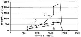
도 16은 알터네이터의 회전 속도에 대한 함수로서(P곡선) 풍력 터빈의 전력의 변화를 KW단위로 나타낸다. 속도는 분당 회전수로 표시된다.16 shows the change in power of the wind turbine (P curve) as a function of the rotational speed of the alternator in KW. The speed is expressed in revolutions per minute.
도 17뿐만 아니라, 도 16에도 또한 표시된 것은, 상수(U/f)를 가진 종래기술에 따라 레귤레이트된 종래의 기계에 대한 회전 속도의 함수로서 전압의 변화(곡선 A)와, 본 발명에 따른 바람직한 기계에 대한 회전 속도의 함수로서 전압의 변화(곡선 V)이다.Also shown in Fig. 16 as well as in Fig. 16 is a variation of the voltage (curve A) as a function of the rotational speed for a conventional machine that has been regulated according to the prior art with a constant (U / f) (Curve V) as a function of the rotational speed for the desired machine.
최적화된 레귤레이팅 전압(U)은 손실을 최소화하기 위해 전력과 속도의 함수로서 산출되었다. 특히, 아이언 로스 및 줄 로스의 균형을 유지하기 위해 용이하게 선택되고, 이는 그것의 합을 최소화하기 위한 것이다.The optimized regulating voltage (U) was calculated as a function of power and speed to minimize losses. In particular, it is readily selected to maintain balance of iron loss and jellows, which is to minimize the sum thereof.
특히 도 17을 더 참조하면, 전력이 감소하는 경우, 불필요하게 기계를 자화(magnetize)하지 않고 과도한 아이언 로스를 발생시키지 않기 위해 전압이 감소하는 것이 보인다. 그래서 특정 속도까지, 특히 정격 속도까지, 최적화된 전압은 최적화되지 않은 전압에 비해 낮을 수 있다.More particularly with reference to FIG. 17, when the power decreases, the voltage appears to decrease unnecessarily without magnetizing the machine and not causing excessive iron loss. So, up to a certain speed, especially up to the rated speed, the optimized voltage may be lower than the unoptimized voltage.
최적화된 전압을 위해 회전속도의 함수로서, 출력 전압(및 그러므로 기준 전압)을 제공하는 곡선은 정격 속도 아래의 직선과 차이가 있을 수 있고, 반대의 경우에는 정격 속도까지 상수(U/f)로 레귤레이션이 수행된다.As a function of the rotational speed for the optimized voltage, the output voltage (and therefore The reference voltage) may be different from the straight line under the rated speed, and in the opposite case, the regulation is performed with a constant (U / f) up to the rated speed.
상수(U/f)를 가진 레귤레이션에 따른 전압이 최대가 되는 경우, 본 발명에 따른 최적화된 U의 속도의 함수로서 전압의 변화는 최대 동작 전압을 얻기 위한 전압 급증 덕분에 킹크(kink)를 보여줄 수 있는데, 이것은 도시된 예에서 분당 1600회전에서, 정격 속도의 수준에서 곡선상에 킹크(kink)가 보인다.When the voltage due to regulation with a constant (U / f) is at its maximum, the change in voltage as a function of the speed of the optimized U according to the invention shows a kink due to the surge in voltage to obtain the maximum operating voltage Which shows a kink on the curve at the level of the rated speed at 1600 revolutions per minute in the example shown.
도 18에서 나타난 것은 분당 회전수로 표시되는 속도의 함수로서, 본 발명에 의해 얻어지는 효율성(B 곡선)과 상수(U/f)를 가진 본 발명이 아닌 효율성(C 곡선)이다. What is shown in FIG. 18 is efficiency (C curve) that is not a present invention with efficiency (B curve) and constant (U / f) obtained by the present invention as a function of the speed expressed in revolutions per minute.
도 18은 본 발명에 의해 얻어진 효율성에서의 개선을 도시한다. 효율성 면에서 이득(G)은, 낮은 속도에서 더 중요한 것으로 보여지는데, 풍력 터빈은 약한 바람에서 더 효과적이다.Figure 18 shows an improvement in efficiency obtained by the present invention. In terms of efficiency, the gain (G) appears to be more important at low speeds, and wind turbines are more effective in weak winds.
다른 의미로 명시되지 않는다면, “포함하는”이라는 표현은 “적어도 하나를 포함하는”과 같은 의미로 이해되어야 한다.Unless otherwise stated, the expression " comprising " should be understood to mean " including at least one. &Quot;
10: 알터네이터 11: 익사이터 12, 16: 스테이터
13, 15: 로터 18, 25: 레귤레이터 9, 19: 네트워크
20: 컨버터 21: 정류기 22: DC 버스
23: 인버터10: alternator 11:
13, 15:
20: converter 21: rectifier 22: DC bus
23: Inverter
Claims (16)
전력이 1MW 이상이고, 권선형 로터(15)를 가지며, 특히 익사이터(11) 또는 스프릿 링과 커뮤테이터에 의한 직접 익사이테이션에 의한, 전압(Vf)을 통해 DC 전류를 공급받고, 출력 전압(Us)을 전달하는 동기식 알터네이터(10); 및
상기 알터네이터의 출력 전압(Us)을 정류하는 정류기(21)를 포함하고, 상기 정류기는 가능한 펄스폭 변조 또는 다이오드기반이고, 선택적으로 DC/DC 컨버터가 수반되는 컨버터(20)
를 포함하고, 공급 전압(Vf)은 상기 알터네이터의 출력 전압(Us)에 종속되는 권선형 로터에 전력을 공급하는 전기기계 어셈블리.An electromechanical assembly that operates in a variety of situations, particularly with varying speeds, powers, or power factors,
The DC power is supplied through the voltage V f by the direct excitation by the exciter 11 or by the splitting and the commutator and the output voltage A synchronous alternator (10) for delivering a signal (U s ); And
And a rectifier (21) for rectifying the output voltage (U s ) of the alternator, wherein the rectifier is a pulse-width-modulated or diode-based, possibly converter (20)
, And wherein the supply voltage (V f ) supplies power to a wired rotor subject to an output voltage (U s ) of the alternator.
미리 정해진 값(Us eff ref)에서 상기 알터네이터의 출력 전압(Us)을 유지하기 위해 상기 전압(Vf)에서 작동하도록 설정된 레귤레이터(18)를 포함하는 전기기계 어셈블리.In the previous paragraph,
The predetermined value (U s eff and a regulator (18) configured to operate at the voltage (V f ) to maintain the output voltage (U s ) of the alternator at a first voltage (V ref ).
상기 기준 전압(Us eff ref)은 다음의 목록으로부터 적어도 하나의 로스를 최소화하기 위해 산출되는 전기기계 어셈블리: 아이언 로스, 맴돌이 전류에 의한 로스, 히스테리시스에 의한 로스, 로터에서 줄효과를 통한 로스, 스테이터에서 줄 효과를 통한 로스, 컨버터에서 전도에 의한 로스, 컨버터에서 스위칭에 의한 로스.In the previous paragraph,
The reference voltage U s eff ref ) is calculated to minimize at least one loss from the following list: electromechanical assembly: iron loss, eddy current loss, hysteresis loss, loss through rotor effect by rotor, , Loss by conduction in converter, loss by switching in converter.
상기 기준 전압(Us eff ref)은 속도, 전력, 역률 및 기계의 열적 상태 중 적어도 하나에 의존하는 전기기계 어셈블리.The method according to any one of the preceding claims,
The reference voltage U s eff ref ) depends on at least one of speed, power, power factor and thermal state of the machine.
상기 기준 전압(Us eff ref)은 어셈블리의 동작 중에 실시간으로 산출되는 전기기계 어셈블리.The method according to any one of the preceding claims,
The reference voltage U s eff ref ) is calculated in real time during operation of the assembly.
상기 기준 전압(Us eff ref)은 어셈블리의 동작에 앞서 어플리케이션의 함수로서 미리 산출되는 전기기계 어셈블리.5. The method according to any one of claims 1 to 4,
The reference voltage U s eff ref ) is calculated in advance as a function of the application prior to operation of the assembly.
상기 알터네이터는 익사이터(11)를 포함하고, 상기 전압(Vr)은 상기 알터네이터(10)에 의해 제공되는 유효 출력 전압(Us eff)에 종속되는 익사이터(11)에서 필요한 익사이테이션을 발생하는 것을 가능하게 하는 전기기계 어셈블리.The method according to any one of the preceding claims,
The alternator includes an exciter (11), and the voltage (V r ) is an effective output voltage (U s ) provided by the alternator (10) electromechanical assembly, which makes it possible to generate the required presentation iksayi exciter (11) is dependent on eff).
상기 권선형 로터(15)에 전원을 공급하는 적어도 하나의 스프릿 링과 커뮤테이터를 포함하는 전기기계 어셈블리.7. The method according to any one of claims 1 to 6,
And at least one splitting ring and a commutator for supplying power to the wound rotor (15).
정류기의 출력 전류는 DC 버스(22)에 전원을 공급하는 전기기계 어셈블리.The method according to any one of the preceding claims,
The output current of the rectifier provides power to the DC bus (22).
일정한 버스 전압을 유지하기 위해 상기 정류기를 제어하는 레귤레이터(25)를 포함하는 전기기계 어셈블리.In the previous paragraph,
And a regulator (25) for controlling said rectifier to maintain a constant bus voltage.
곡선은 회전 속도(분당 회전수)의 함수로서 상기 알터네이터의 출력 전압(Us)을 제공하고, 회전 속도가 정격 속도에 도달하면 킹크를 표시하는 전기기계 어셈블리.The method according to any one of the preceding claims,
The curve provides the output voltage (U s ) of the alternator as a function of the rotational speed (revolutions per minute), and displays the kink when the rotational speed reaches the rated speed.
곡선은 회전 속도(분당 회전수)의 함수로서 상기 알터네이터의 출력 전압(Us)을 제공하고, 정격 속도 아래의 회전 속도에서 직선과 차이가 있는 전기기계 어셈블리.The method according to any one of the preceding claims,
The curve provides the output voltage (U s ) of the alternator as a function of the rotational speed (revolutions per minute) and is different from the straight line at the rotational speed below the rated speed.
상기 출력 전압(Us)은, 정격 속도 아래의 회전 속도에서, 레귤레이션의 관점에서 정격 속도까지의 속도의 전 범위를 넘어서 상수(U/f)를 가진 레귤레이팅 전압보다 낮은 전기기계 어셈블리.The method according to any one of the preceding claims,
Wherein the output voltage (U s ) is lower than a regulating voltage having a constant (U / f) over the full range of speeds from the regulatory viewpoint to the rated speed, at a rotational speed below the rated speed.
권선형 로터(15)를 가진 동기식 알터네이터(10)의 로터는 알터네이터의 출력 전압(Us)에 종속되는 전압(Vf)에서 DC 전류를 공급받는 기계적 에너지를 전기적 에너지로 변환하는 방법.A method for converting wind energy based mechanical energy into electrical energy, in particular by means of an assembly according to at least one of the claims 1 to 10,
A rotor of a synchronous alternator (10) having a winding rotor (15) converts the mechanical energy supplied to the DC current at a voltage (V f ) dependent on the output voltage (U s ) of the alternator to electrical energy.
상기 알터네이터의 출력 전압(Us)은 펄스폭 변조 타입의 정류기에 의해 정류되는 기계적 에너지를 전기적 에너지로 변환하는 방법.
In the previous paragraph,
Wherein the output voltage (U s ) of the alternator is converted into mechanical energy that is rectified by a rectifier of a pulse width modulation type.
Applications Claiming Priority (3)
| Application Number | Priority Date | Filing Date | Title |
|---|---|---|---|
| FR1151281 | 2011-02-16 | ||
| FR1151281A FR2971648B1 (en) | 2011-02-16 | 2011-02-16 | VARIABLE-RATE OPERATING ASSEMBLY HAVING SYNCHRONOUS ROTOR-ROLLER ALTERNATOR AND CONVERTER |
| PCT/IB2012/050717 WO2012110979A1 (en) | 2011-02-16 | 2012-02-16 | Assembly operating in a variable regime |
Publications (1)
| Publication Number | Publication Date |
|---|---|
| KR20140051825A true KR20140051825A (en) | 2014-05-02 |
Family
ID=45774286
Family Applications (1)
| Application Number | Title | Priority Date | Filing Date |
|---|---|---|---|
| KR1020137021635A KR20140051825A (en) | 2011-02-16 | 2012-02-16 | Assembly operating in a variable regime |
Country Status (7)
| Country | Link |
|---|---|
| US (1) | US9431943B2 (en) |
| EP (1) | EP2676362A1 (en) |
| JP (3) | JP2014506113A (en) |
| KR (1) | KR20140051825A (en) |
| CN (1) | CN102647139B (en) |
| FR (1) | FR2971648B1 (en) |
| WO (1) | WO2012110979A1 (en) |
Families Citing this family (19)
| Publication number | Priority date | Publication date | Assignee | Title |
|---|---|---|---|---|
| GB2491548A (en) * | 2010-09-30 | 2012-12-12 | Vestas Wind Sys As | Over-rating control of a wind turbine power plant |
| CN103378783A (en) * | 2012-04-16 | 2013-10-30 | 台达电子企业管理(上海)有限公司 | Excitation control circuit, excitation control method, and electrical excitation wind power system of excitation control circuit |
| EP2741392A3 (en) * | 2012-12-04 | 2016-12-14 | ABB Research Ltd. | Systems and methods for utilizing an active compensator to augment a diode rectifier |
| CN103607154B (en) * | 2013-11-12 | 2017-02-01 | 北京工业大学 | Method for controlling AC motor capable of electrical excitation |
| US20150249417A1 (en) * | 2013-12-30 | 2015-09-03 | Rolls-Royce Corporation | Synchronous generator controller based on flux optimizer |
| FR3022416B1 (en) * | 2014-06-11 | 2017-08-25 | Valeo Equip Electr Moteur | CONTROL LOOP OF A DIGITAL REGULATOR DEVICE OF ROTATING ELECTRIC MACHINE WITH EXCITATION OF A MOTOR VEHICLE |
| JP6269355B2 (en) * | 2014-07-04 | 2018-01-31 | 株式会社安川電機 | Matrix converter, power generation system, and power factor control method |
| US11296638B2 (en) | 2014-08-01 | 2022-04-05 | Falcon Power, LLC | Variable torque motor/generator/transmission |
| EP3175538B1 (en) | 2014-08-01 | 2020-06-24 | Falcon Power LLC | Variable torque motor/generator/transmission |
| US9447772B2 (en) * | 2014-12-18 | 2016-09-20 | General Electric Company | Systems and methods for increasing wind turbine power output |
| FR3033458B1 (en) | 2015-03-05 | 2018-06-15 | Moteurs Leroy-Somer | ELECTROMECHANICAL ASSEMBLY COMPRISING AN ALTERNATOR |
| JP6559487B2 (en) * | 2015-07-08 | 2019-08-14 | 株式会社東芝 | Secondary excitation device control device, control method, and variable speed pumped storage power generation system |
| FR3040558B1 (en) * | 2015-08-28 | 2017-08-11 | Valeo Equip Electr Moteur | CIRCUIT FOR EXCITATION OF A MOTOR VEHICLE ALTERNATOR, VOLTAGE REGULATOR AND ALTERNATOR INCORPORATING IT |
| CN105201750A (en) * | 2015-10-16 | 2015-12-30 | 岑益南 | Double-wind-wheel direct-drive windmill generator |
| KR102587804B1 (en) * | 2016-04-13 | 2023-10-11 | 팔콘 파워, 엘엘씨 | Variable torque motor/generator/transmission |
| DE102017201687A1 (en) * | 2017-02-02 | 2018-08-02 | Siemens Aktiengesellschaft | A controllable voltage generating device and method for operating a controllable voltage generating device |
| US10483886B2 (en) * | 2017-09-14 | 2019-11-19 | Hamilton Sundstrand Corportion | Modular electric power generating system with multistage axial flux generator |
| KR102310629B1 (en) * | 2019-01-24 | 2021-10-07 | 전북대학교산학협력단 | A field excitation system and method for a wound rotor synchronous generator |
| US11671038B2 (en) * | 2019-08-09 | 2023-06-06 | Hamilton Sundstrand Corporation | Control of a wound field synchronous generator for transient load response |
Family Cites Families (10)
| Publication number | Priority date | Publication date | Assignee | Title |
|---|---|---|---|---|
| US5083039B1 (en) * | 1991-02-01 | 1999-11-16 | Zond Energy Systems Inc | Variable speed wind turbine |
| DE19845903A1 (en) * | 1998-10-05 | 2000-04-06 | Aloys Wobben | Electrical power transmission system |
| DE19849889A1 (en) * | 1998-10-29 | 2000-05-04 | Bosch Gmbh Robert | Process for the performance and efficiency-optimized control of synchronous machines |
| US6456514B1 (en) * | 2000-01-24 | 2002-09-24 | Massachusetts Institute Of Technology | Alternator jump charging system |
| DE10044181A1 (en) * | 2000-09-07 | 2002-04-04 | Bosch Gmbh Robert | Controller structure for electrical machines |
| EP1289118A1 (en) * | 2001-08-24 | 2003-03-05 | Siemens Aktiengesellschaft | Method and arrangement for starting a turbo set |
| JP4899800B2 (en) * | 2006-02-28 | 2012-03-21 | 株式会社日立製作所 | Wind turbine generator, wind turbine generator system and power system controller |
| JP5013372B2 (en) * | 2007-09-06 | 2012-08-29 | 国立大学法人 琉球大学 | Manufacturing method of storage battery equipment for wind power generator |
| JP2009232497A (en) * | 2008-03-19 | 2009-10-08 | Mitsubishi Electric Corp | Control device of generator voltage |
| JP5167106B2 (en) * | 2008-12-22 | 2013-03-21 | 株式会社日立エンジニアリング・アンド・サービス | Wind power plant and its power generation control method |
-
2011
- 2011-02-16 FR FR1151281A patent/FR2971648B1/en active Active
-
2012
- 2012-02-16 KR KR1020137021635A patent/KR20140051825A/en not_active Application Discontinuation
- 2012-02-16 WO PCT/IB2012/050717 patent/WO2012110979A1/en active Application Filing
- 2012-02-16 JP JP2013554043A patent/JP2014506113A/en active Pending
- 2012-02-16 EP EP12706701.5A patent/EP2676362A1/en not_active Withdrawn
- 2012-02-16 CN CN201210035643.0A patent/CN102647139B/en not_active Expired - Fee Related
-
2013
- 2013-07-31 US US13/955,788 patent/US9431943B2/en not_active Expired - Fee Related
-
2017
- 2017-02-24 JP JP2017034049A patent/JP2017093296A/en active Pending
-
2019
- 2019-06-18 JP JP2019113086A patent/JP2019149936A/en not_active Abandoned
Also Published As
| Publication number | Publication date |
|---|---|
| JP2019149936A (en) | 2019-09-05 |
| JP2017093296A (en) | 2017-05-25 |
| CN102647139B (en) | 2016-12-07 |
| EP2676362A1 (en) | 2013-12-25 |
| US9431943B2 (en) | 2016-08-30 |
| WO2012110979A1 (en) | 2012-08-23 |
| CN102647139A (en) | 2012-08-22 |
| JP2014506113A (en) | 2014-03-06 |
| US20130313828A1 (en) | 2013-11-28 |
| FR2971648A1 (en) | 2012-08-17 |
| FR2971648B1 (en) | 2016-10-14 |
Similar Documents
| Publication | Publication Date | Title |
|---|---|---|
| KR20140051825A (en) | Assembly operating in a variable regime | |
| US8193654B2 (en) | Variable speed power generator having two induction generators on a common shaft | |
| McMahon et al. | The BDFM as a generator in wind turbines | |
| CN102629766B (en) | Relax the electric unbalanced system and method for the three-phase current at point of common coupling place | |
| CN103541860B (en) | Method and apparatus for adaptively controlling wind power plant turbine | |
| DK2149964T3 (en) | Synchronous Generator synchronous generator system | |
| KR102095978B1 (en) | How to control a synchronous generator of a gearless wind turbine | |
| US10491146B2 (en) | System and method for compensating for generator-induced flicker in a wind turbine | |
| CN106168195A (en) | The restriction of the fall volume plan for using in wind turbine control | |
| Guerroudj et al. | Performance analysis of Vernier slotted doubly salient permanent magnet generator for wind power | |
| GB2489411A (en) | Control of a single phase brushless doubly fed generator | |
| Bhattacherjee et al. | Brushless synchronous generator-unidirectional rectifier for offshore wind energy conversion system | |
| JP2005304271A (en) | Synchronous generator and wind-power generation system | |
| Ani et al. | Energy yield of two generator systems for small wind turbine application | |
| KR101417509B1 (en) | Synchronous generator system haing dual rotor | |
| GB2460723A (en) | Operating a brushless doubly fed machine (BDFM) | |
| Gursoy et al. | Representation of variable speed wind turbine generators for short circuit analysis | |
| EP2562417A1 (en) | Three-phase electrical generator and system for turbines | |
| Afandi et al. | Analysis of Load Fluctuation Effect on the Excitation Current of the Three-Phase Synchronous Generator at the Diesel Power Plant | |
| Amuhaya et al. | Effect of rotor field winding MMF on performance of grid-compliant hybrid-PM slip synchronous wind generator | |
| La Seta et al. | New control scheme for doubly-fed induction generators to improve transient stability | |
| Metwally | Operation of new variable speed constant voltage and frequency generator connected to the grid | |
| JP2014045649A (en) | Electrical machine and method for operating electrical machine | |
| Bhattacherjee et al. | A Brushless Synchronous Generator for Standalone DC Applications | |
| US20230246574A1 (en) | System and method for providing grid-forming control of an inverter-based resource |
Legal Events
| Date | Code | Title | Description |
|---|---|---|---|
| WITN | Application deemed withdrawn, e.g. because no request for examination was filed or no examination fee was paid |