KR20140051760A - Environmental-friendly heat exchanger - Google Patents
Environmental-friendly heat exchanger Download PDFInfo
- Publication number
- KR20140051760A KR20140051760A KR1020130056160A KR20130056160A KR20140051760A KR 20140051760 A KR20140051760 A KR 20140051760A KR 1020130056160 A KR1020130056160 A KR 1020130056160A KR 20130056160 A KR20130056160 A KR 20130056160A KR 20140051760 A KR20140051760 A KR 20140051760A
- Authority
- KR
- South Korea
- Prior art keywords
- heat exchange
- heat exchanger
- tube
- heat
- exchange tube
- Prior art date
Links
Images

Classifications
-
- F—MECHANICAL ENGINEERING; LIGHTING; HEATING; WEAPONS; BLASTING
- F24—HEATING; RANGES; VENTILATING
- F24H—FLUID HEATERS, e.g. WATER OR AIR HEATERS, HAVING HEAT-GENERATING MEANS, e.g. HEAT PUMPS, IN GENERAL
- F24H9/00—Details
- F24H9/0005—Details for water heaters
-
- F—MECHANICAL ENGINEERING; LIGHTING; HEATING; WEAPONS; BLASTING
- F28—HEAT EXCHANGE IN GENERAL
- F28D—HEAT-EXCHANGE APPARATUS, NOT PROVIDED FOR IN ANOTHER SUBCLASS, IN WHICH THE HEAT-EXCHANGE MEDIA DO NOT COME INTO DIRECT CONTACT
- F28D7/00—Heat-exchange apparatus having stationary tubular conduit assemblies for both heat-exchange media, the media being in contact with different sides of a conduit wall
- F28D7/16—Heat-exchange apparatus having stationary tubular conduit assemblies for both heat-exchange media, the media being in contact with different sides of a conduit wall the conduits being arranged in parallel spaced relation
- F28D7/1607—Heat-exchange apparatus having stationary tubular conduit assemblies for both heat-exchange media, the media being in contact with different sides of a conduit wall the conduits being arranged in parallel spaced relation with particular pattern of flow of the heat exchange media, e.g. change of flow direction
-
- F—MECHANICAL ENGINEERING; LIGHTING; HEATING; WEAPONS; BLASTING
- F28—HEAT EXCHANGE IN GENERAL
- F28F—DETAILS OF HEAT-EXCHANGE AND HEAT-TRANSFER APPARATUS, OF GENERAL APPLICATION
- F28F9/00—Casings; Header boxes; Auxiliary supports for elements; Auxiliary members within casings
- F28F9/007—Auxiliary supports for elements
- F28F9/013—Auxiliary supports for elements for tubes or tube-assemblies
-
- F—MECHANICAL ENGINEERING; LIGHTING; HEATING; WEAPONS; BLASTING
- F28—HEAT EXCHANGE IN GENERAL
- F28D—HEAT-EXCHANGE APPARATUS, NOT PROVIDED FOR IN ANOTHER SUBCLASS, IN WHICH THE HEAT-EXCHANGE MEDIA DO NOT COME INTO DIRECT CONTACT
- F28D21/00—Heat-exchange apparatus not covered by any of the groups F28D1/00 - F28D20/00
- F28D2021/0019—Other heat exchangers for particular applications; Heat exchange systems not otherwise provided for
- F28D2021/0035—Other heat exchangers for particular applications; Heat exchange systems not otherwise provided for for domestic or space heating, e.g. heating radiators
Abstract
Description
The present invention relates to an environmentally friendly heat exchanger, and more particularly, to an environmentally friendly heat exchanger for reducing carbon monoxide generation by gently lowering the temperature of a combustion gas passing through a heat exchanger through a structure improvement of the heat exchanger.
The present invention also relates to an environment-friendly heat exchanger capable of preventing overheating and deformation of the heat exchanger and reducing the overall size thereof.
Further, the present invention relates to an environment-friendly heat exchanger which improves the shape of a 'U' -shaped connection pipe connecting heat exchange tubes to each other to thereby reduce the occurrence of breakage or noise due to water impact while increasing the heat exchange rate.
The heat exchanger makes heat transfer by crossing the heating fluid and the heating fluid having different temperatures from each other, and is widely used for heating, air conditioning, power generation, cooling and waste heat recovery in various heating and cooling apparatuses including a boiler and an air conditioner. Is used.
Particularly, as shown in FIG. 1, the condensing boiler uses a
However, in the conventional
That is, when the flame and the high-temperature combustion gas generated in the
Accordingly, there is a problem that not only the human body is harmed when leaking into the room, but also the amount of carbon monoxide (CO), which is a main cause of environmental pollution, increases.
In the conventional
SUMMARY OF THE INVENTION The present invention has been proposed in order to solve the above-mentioned problems, and it is an object of the present invention to improve the structure of a heat exchanger to gently lower the temperature of a combustion gas passing through a heat exchanger to suppress generation of carbon monoxide, Friendly heat exchanger that reduces the overall size of the U-shaped connector and prevents damage or noise caused by water impact in the U-shaped connector.
To this end, the eco-friendly heat exchanger according to the present invention includes a plurality of first heat exchange tubes installed in a heat exchanger body, and a plurality of second heat exchange tubes and an eco-friendly heat exchanger that circulates water through the plurality of second heat exchange tubes and the third heat exchange tubes, Wherein the heat exchanger body comprises a front / rear / left / right side plate; The first heat exchange tubes are connected to each other in the zigzag direction through the left and right side plates and the heat exchange fins are assembled to the outer periphery of the left and right side plates and the second heat exchange tubes are connected to each other in the zigzag direction through the left and right side plates, The third heat exchanger tube is installed along the inner circumferential surface of the heat exchanger body and supports the inner circumferential surface of the heat exchanger body.
At this time, the first heat exchange tube having the heat exchange fin is installed in the lower part of the body of the heat exchanger so as to be installed at a position distant from the direction of supplying the hot heat source, and the second heat exchange tube without the heat exchange fin, And the heat exchange tube is installed in the remaining portion of the heat exchanger body where the first heat exchange tube is not installed.
Preferably, the second heat exchange tube is disposed on the upper portion of the first heat exchange tube, and the third heat exchange tube is disposed on the upper portion of the second heat exchange tube.
It is preferable that the first heat exchange tube and the second heat exchange tube are fixed to the left and right side plates by welding and the outlet port of the third heat exchange tube is fixed to the front side plate by welding.
Further, it is preferable that the contact tube further includes a contact tube which is installed in contact with the inner surface of the front / rear side plate, and the contact tube is connected to the second heat exchange tube so that water flows through the contact tube.
Further, it is preferable that an insulating plate is inserted into the inner side surfaces of the left and right side plates.
Further, the inner circumferential surface of the left / right side plate into which the heat insulating plate is inserted is provided with an embossed portion protruding inwardly in contact with the heat insulating plate, thereby forming a heat insulating space between the left / right side plate and the heat insulating plate.
The first heat exchange pipe is an oval pipe having an elliptical cross section, and the 'U' -shaped pipe connecting the ends of the two obtuse pipes includes a straight portion and a curved portion, and the 'U' The length of the straight portion of the connecting pipe is preferably 10 mm or more and 15 mm or less.
The height of the U-shaped connecting pipe is preferably 30.5 mm or more and 35.5 mm or less.
Also, it is preferable that the long axis outer diameter of the U-shaped connecting pipe is 26 mm or more and 29 mm or less, and the uniaxial outer diameter of the U-shaped connecting pipe is 13 mm or more and 16 mm or less.
According to the present invention, the first to third heat exchanger tubes of different types are adopted as the heat exchanger tubes and the installation structure thereof is improved, so that the temperature gradient inside the heat exchanger gently drops and the generation of carbon monoxide is suppressed.
In addition, the present invention prevents the deformation of the heat exchanger by fixing the first heat exchanger tube and the second heat exchanger tube to the side plate of the heat exchanger body while supporting the inner side surface of the heat exchanger body with the third heat exchanger tube.
The present invention also prevents deformation of the heat exchanger body by preventing the heat exchanger body from being overheated by using the contact tube, the heat insulating plate, and the heat insulating space.
In addition, when the off-pipe is used as the first heat exchange pipe, the shape of the 'U' -shaped pipe connecting them is optimized so that the heat exchange rate can be increased and the occurrence of breakage or noise due to water impact can be reduced.
1 is a cross-sectional view of a condensing boiler employing a conventional heat exchanger.
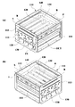
2 is a perspective view of an environment-friendly heat exchanger according to the present invention.
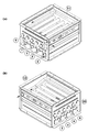
3 is a view showing a water circulation state of the environment-friendly heat exchanger according to the present invention.
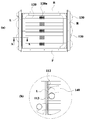
4 is a bottom view and an AA cross-sectional view of the environmentally friendly heat exchanger according to the present invention.
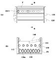
5 is a front view and a BB sectional view of the environment-friendly heat exchanger according to the present invention.
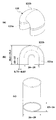
6 is a view showing a 'U' -shaped connection pipe of an environmentally friendly heat exchanger according to the present invention.
Hereinafter, an environment-friendly heat exchanger according to a preferred embodiment of the present invention will be described with reference to the accompanying drawings.
In the following description, the direction in which the burner is installed is set to the upper side and the opposite side is set to the lower side, but it is obvious that the vertical direction can be changed depending on the installation position of the burner.
In the following description, the body of the heat exchanger is divided into the front / rear / left / right side plates, but it is obvious that the front / rear / left / right directions can be changed depending on the viewing angle.
In the following description, the inlet and outlet are specified, but it is obvious that if the flow of water is changed by a design change, the inlet may be the outlet and the outlet may be the inlet.
2 and 3, the environment-friendly heat exchanger according to the present invention includes a
At this time, the first
FIG. 3 shows the flow of water along the first
The upper and lower portions of the
Accordingly, heat is exchanged between the water circulating through the first
Here, the
Thus, if a burner is installed on top of the
The first
The front side plate F and the rear side plate B are provided with
The
If the
As shown in Fig. 4 (b) showing the A-A cross section in Fig. 4 (a), the
The inner circumferential surfaces of the left side plate L and the right side plate R in which the
When the embossed
The first heat exchange tube (120) is composed of a plurality of tubes. In one embodiment, each first
The first
That is, the first
The first
When the first
For example, a side of the first
Meanwhile, when a mist pipe is used as the first
This " U " shaped
The U-shaped connecting
Since the
Therefore, it is possible to prevent breakage and noise generation of the
The total height of the U-shaped connecting
This means that the curvature of the
In addition, as shown in FIG. 6 (c), the U-shaped connecting
Therefore, the U
A plurality of second
The second
When the second
The third
Accordingly, the third
The outflow end of the third
The present invention is different from the prior art in that a plurality of heat exchange tubes are not the same, but a first
The first
The second
The reason for this is to prevent the generation of carbon monoxide (CO) as the temperature is rapidly lowered in the process of passing the high-temperature combustion gas through the heat exchanger of the present invention.
The amount of heat absorption is relatively smaller in the second
In addition, the first
That is, the present invention suppresses carbon monoxide generation due to a rapid decrease in the temperature of the combustion gas while having a high thermal efficiency. Therefore, it is possible to prevent the carbon monoxide from entering the room or the like to cause harm to the human body, and to significantly reduce the emission of carbon monoxide harmful to the environment.
The specific embodiments of the present invention have been described above. It is to be understood, however, that the scope and spirit of the present invention is not limited to these specific embodiments, and that various modifications and changes may be made without departing from the spirit of the present invention. If you have, you will understand.
Therefore, it should be understood that the above-described embodiments are provided so that those skilled in the art can fully understand the scope of the present invention. Therefore, it should be understood that the embodiments are to be considered in all respects as illustrative and not restrictive, The invention is only defined by the scope of the claims.
110: heat exchanger body 111: contact tube
112: insulating plate 113: embossed portion
120: first
121:
121b: Curved portion 130: Second heat exchanger tube
140: Third heat exchanger tube
L: left side plate R: right side plate
F: front side plate B: rear side plate
IN: Inlet OUT: Outlet
Claims (10)
The heat exchanger body 110 is composed of front / rear / left / right side plates F, B, L, R;
The first heat exchange tubes 120 are connected to each other in the zigzag direction through the left and right side plates L and R and a heat exchange fin 120a is assembled to the outer circumference of the first heat exchange tubes 120,
The second heat exchange tubes 130 are connected to each other in the zigzag direction through the left and right side plates L and R,
Wherein the third heat exchanger tube (140) is installed along the inner circumferential surface of the heat exchanger body (110) and supports the inner circumferential surface of the heat exchanger body (110).
The first heat exchange tube 120 having the heat exchange fin 120a is installed at a lower portion of the heat exchanger body 110 so as to be installed at a position distant from the direction in which the high temperature heat source is supplied,
The second heat exchange tube 130 and the third heat exchange tube 140 without the heat exchange fin 120a are installed in the remaining portion of the heat exchanger body 110 where the first heat exchange tube 120 is not installed Wherein the heat exchanger is a heat exchanger.
The second heat exchange tube 130 is installed on the upper portion of the first heat exchange tube 120 and the third heat exchange tube 140 is installed on the upper portion of the second heat exchange tube 130 Eco-friendly heat exchanger.
The first heat exchange tube 120 and the second heat exchange tube 130 are welded to the left and right side plates L and R and the outlet OUT of the third heat exchange tube 140 is fixed to the front side plate (F) by welding. ≪ RTI ID = 0.0 > 8. < / RTI >
Further comprising a contact tube (111) provided in contact with the inner surface of the front and rear side plates (F, B), wherein the contact tube (111) (130). ≪ / RTI >
Wherein an insulation plate (112) is inserted into the inner side surfaces of the left and right side plates (L, R).
The left and right side plates L and R having the heat insulating plate 112 inserted therein are provided with an embossing portion 113 protruding inward and in contact with the heat insulating plate 112, R) and the heat insulating plate (112).
The first heat exchange pipe 120 is an oval pipe having an elliptical cross section and the U-shaped connection pipe 121 connecting the end portions of the two fault pipes has a straight portion 121a and a curved portion 121b), and the length of the straight portion (121a) of the U-shaped connecting tube (121) is 10 mm or more and 15 mm or less.
The height of the U-shaped connecting tube (121) is not less than 30.5 mm and not more than 35.5 mm.
Wherein the U-shaped connecting pipe 121 has a major axis outer diameter of 26 mm or more and 29 mm or less, and the U-shaped connecting pipe 121 has a minor axis outer diameter of 13 mm or more and 16 mm or less.
Priority Applications (1)
| Application Number | Priority Date | Filing Date | Title |
|---|---|---|---|
| PCT/KR2014/004468 WO2014189244A1 (en) | 2013-05-20 | 2014-05-19 | Eco-friendly heat exchanger |
Applications Claiming Priority (2)
| Application Number | Priority Date | Filing Date | Title |
|---|---|---|---|
| KR20120117610 | 2012-10-23 | ||
| KR1020120117610 | 2012-10-23 |
Publications (1)
| Publication Number | Publication Date |
|---|---|
| KR20140051760A true KR20140051760A (en) | 2014-05-02 |
Family
ID=50885348
Family Applications (1)
| Application Number | Title | Priority Date | Filing Date |
|---|---|---|---|
| KR1020130056160A KR20140051760A (en) | 2012-10-23 | 2013-05-20 | Environmental-friendly heat exchanger |
Country Status (1)
| Country | Link |
|---|---|
| KR (1) | KR20140051760A (en) |
Cited By (6)
| Publication number | Priority date | Publication date | Assignee | Title |
|---|---|---|---|---|
| WO2016017864A1 (en) * | 2014-08-01 | 2016-02-04 | (주)귀뚜라미 | High-efficiency eco-friendly sensible-heat heat exchanger |
| EP3236175A1 (en) * | 2016-04-18 | 2017-10-25 | Daesung Celtic Enersys Co., Ltd. | Heat exchanger |
| CN109297194A (en) * | 2018-10-23 | 2019-02-01 | 广东万家乐燃气具有限公司 | Heat exchanger and water heater |
| US20210199340A1 (en) * | 2019-12-30 | 2021-07-01 | Kyungdong Navien Co., Ltd | Heat exchanger unit and method for manufacturing the same |
| US11585572B2 (en) | 2018-06-05 | 2023-02-21 | Kyungdong Navien Co., Ltd. | Heat exchanger unit and condensing boiler using the same |
| US11835262B2 (en) | 2018-06-05 | 2023-12-05 | Kyungdong Navien Co., Ltd. | Heat exchanger unit |
-
2013
- 2013-05-20 KR KR1020130056160A patent/KR20140051760A/en not_active Application Discontinuation
Cited By (8)
| Publication number | Priority date | Publication date | Assignee | Title |
|---|---|---|---|---|
| WO2016017864A1 (en) * | 2014-08-01 | 2016-02-04 | (주)귀뚜라미 | High-efficiency eco-friendly sensible-heat heat exchanger |
| EP3236175A1 (en) * | 2016-04-18 | 2017-10-25 | Daesung Celtic Enersys Co., Ltd. | Heat exchanger |
| US11585572B2 (en) | 2018-06-05 | 2023-02-21 | Kyungdong Navien Co., Ltd. | Heat exchanger unit and condensing boiler using the same |
| US11835262B2 (en) | 2018-06-05 | 2023-12-05 | Kyungdong Navien Co., Ltd. | Heat exchanger unit |
| US11835261B2 (en) | 2018-06-05 | 2023-12-05 | Kyungdong Navien Co., Ltd. | Heat exchanger unit |
| US11879666B2 (en) | 2018-06-05 | 2024-01-23 | Kyungdong Navien Co., Ltd. | Heat exchanger unit |
| CN109297194A (en) * | 2018-10-23 | 2019-02-01 | 广东万家乐燃气具有限公司 | Heat exchanger and water heater |
| US20210199340A1 (en) * | 2019-12-30 | 2021-07-01 | Kyungdong Navien Co., Ltd | Heat exchanger unit and method for manufacturing the same |
Similar Documents
| Publication | Publication Date | Title |
|---|---|---|
| KR20140051760A (en) | Environmental-friendly heat exchanger | |
| JP5043859B2 (en) | Condenser boiler heat exchanger for heating and hot water supply | |
| KR100570291B1 (en) | Basic heat exchanger of boiler | |
| JP2007183027A (en) | Heat exchanger for recovering latent heat | |
| JP4773374B2 (en) | Heat exchanger | |
| JP2007183029A (en) | Heat exchanger for recovering latent heat | |
| CN104566981A (en) | Flue gas condensation recovery device of gas heating hot water boiler | |
| KR100473083B1 (en) | heat exchanger of condensing boiler | |
| KR20180007984A (en) | Structure for preventing combustion heat loss of heat exchanger | |
| CN105157228A (en) | Water-tube type central-reverse-flame and condensation integrated boiler | |
| KR20160015945A (en) | High efficiency environmental-friendly sensible heat exchanger | |
| KR19990070599A (en) | Dual structure heat exchanger for condensing gas boiler | |
| EP3249293B1 (en) | Hot water boiler | |
| CN201251278Y (en) | Wet-back gas-fired hot water modular cast iron boiler | |
| CN2929610Y (en) | Direct heat exchange type coal burning hot blast stove | |
| KR20140051522A (en) | Heat exchanger having water housing | |
| KR100391258B1 (en) | The gas boiler's heat exchanger which has a type of condensing latent heat | |
| KR100437667B1 (en) | condensing Gas boiler using uptrend combustion type for withdraw latent heat | |
| CN209763498U (en) | combustor and gas heater | |
| CN110118435B (en) | Wall-hanging stove heat exchanger | |
| CN212842199U (en) | Heat exchanger of gas water heater | |
| KR200362832Y1 (en) | Heat exchanger of condensing boiler | |
| CN217131295U (en) | Pipe clamp pipe structure of heating surface of solid waste incineration boiler | |
| CN209588013U (en) | A kind of horizontal three return smokes fire tube steam boiler | |
| JP2007183028A (en) | Heat exchanger for recovering latent heat |
Legal Events
| Date | Code | Title | Description |
|---|---|---|---|
| A201 | Request for examination | ||
| E902 | Notification of reason for refusal | ||
| E601 | Decision to refuse application | ||
| J201 | Request for trial against refusal decision | ||
| J301 | Trial decision |
Free format text: TRIAL DECISION FOR APPEAL AGAINST DECISION TO DECLINE REFUSAL REQUESTED 20150309 Effective date: 20151123 |