KR20140049936A - Method for monitoring the tightness of a fuel tank system - Google Patents
Method for monitoring the tightness of a fuel tank system Download PDFInfo
- Publication number
- KR20140049936A KR20140049936A KR1020130122921A KR20130122921A KR20140049936A KR 20140049936 A KR20140049936 A KR 20140049936A KR 1020130122921 A KR1020130122921 A KR 1020130122921A KR 20130122921 A KR20130122921 A KR 20130122921A KR 20140049936 A KR20140049936 A KR 20140049936A
- Authority
- KR
- South Korea
- Prior art keywords
- fuel tank
- pressure
- tank system
- accumulator
- internal combustion
- Prior art date
Links
Images
Classifications
-
- F—MECHANICAL ENGINEERING; LIGHTING; HEATING; WEAPONS; BLASTING
- F02—COMBUSTION ENGINES; HOT-GAS OR COMBUSTION-PRODUCT ENGINE PLANTS
- F02B—INTERNAL-COMBUSTION PISTON ENGINES; COMBUSTION ENGINES IN GENERAL
- F02B37/00—Engines characterised by provision of pumps driven at least for part of the time by exhaust
- F02B37/12—Control of the pumps
-
- F—MECHANICAL ENGINEERING; LIGHTING; HEATING; WEAPONS; BLASTING
- F02—COMBUSTION ENGINES; HOT-GAS OR COMBUSTION-PRODUCT ENGINE PLANTS
- F02D—CONTROLLING COMBUSTION ENGINES
- F02D41/00—Electrical control of supply of combustible mixture or its constituents
- F02D41/22—Safety or indicating devices for abnormal conditions
-
- F—MECHANICAL ENGINEERING; LIGHTING; HEATING; WEAPONS; BLASTING
- F02—COMBUSTION ENGINES; HOT-GAS OR COMBUSTION-PRODUCT ENGINE PLANTS
- F02B—INTERNAL-COMBUSTION PISTON ENGINES; COMBUSTION ENGINES IN GENERAL
- F02B33/00—Engines characterised by provision of pumps for charging or scavenging
- F02B33/44—Passages conducting the charge from the pump to the engine inlet, e.g. reservoirs
-
- F—MECHANICAL ENGINEERING; LIGHTING; HEATING; WEAPONS; BLASTING
- F02—COMBUSTION ENGINES; HOT-GAS OR COMBUSTION-PRODUCT ENGINE PLANTS
- F02B—INTERNAL-COMBUSTION PISTON ENGINES; COMBUSTION ENGINES IN GENERAL
- F02B37/00—Engines characterised by provision of pumps driven at least for part of the time by exhaust
-
- F—MECHANICAL ENGINEERING; LIGHTING; HEATING; WEAPONS; BLASTING
- F02—COMBUSTION ENGINES; HOT-GAS OR COMBUSTION-PRODUCT ENGINE PLANTS
- F02M—SUPPLYING COMBUSTION ENGINES IN GENERAL WITH COMBUSTIBLE MIXTURES OR CONSTITUENTS THEREOF
- F02M25/00—Engine-pertinent apparatus for adding non-fuel substances or small quantities of secondary fuel to combustion-air, main fuel or fuel-air mixture
- F02M25/08—Engine-pertinent apparatus for adding non-fuel substances or small quantities of secondary fuel to combustion-air, main fuel or fuel-air mixture adding fuel vapours drawn from engine fuel reservoir
- F02M25/0809—Judging failure of purge control system
- F02M25/0818—Judging failure of purge control system having means for pressurising the evaporative emission space
-
- G—PHYSICS
- G01—MEASURING; TESTING
- G01M—TESTING STATIC OR DYNAMIC BALANCE OF MACHINES OR STRUCTURES; TESTING OF STRUCTURES OR APPARATUS, NOT OTHERWISE PROVIDED FOR
- G01M3/00—Investigating fluid-tightness of structures
- G01M3/02—Investigating fluid-tightness of structures by using fluid or vacuum
- G01M3/26—Investigating fluid-tightness of structures by using fluid or vacuum by measuring rate of loss or gain of fluid, e.g. by pressure-responsive devices, by flow detectors
-
- Y—GENERAL TAGGING OF NEW TECHNOLOGICAL DEVELOPMENTS; GENERAL TAGGING OF CROSS-SECTIONAL TECHNOLOGIES SPANNING OVER SEVERAL SECTIONS OF THE IPC; TECHNICAL SUBJECTS COVERED BY FORMER USPC CROSS-REFERENCE ART COLLECTIONS [XRACs] AND DIGESTS
- Y02—TECHNOLOGIES OR APPLICATIONS FOR MITIGATION OR ADAPTATION AGAINST CLIMATE CHANGE
- Y02T—CLIMATE CHANGE MITIGATION TECHNOLOGIES RELATED TO TRANSPORTATION
- Y02T10/00—Road transport of goods or passengers
- Y02T10/10—Internal combustion engine [ICE] based vehicles
- Y02T10/12—Improving ICE efficiencies
Landscapes
- Engineering & Computer Science (AREA)
- Chemical & Material Sciences (AREA)
- Combustion & Propulsion (AREA)
- Mechanical Engineering (AREA)
- General Engineering & Computer Science (AREA)
- Physics & Mathematics (AREA)
- General Physics & Mathematics (AREA)
- Supplying Secondary Fuel Or The Like To Fuel, Air Or Fuel-Air Mixtures (AREA)
- Cooling, Air Intake And Gas Exhaust, And Fuel Tank Arrangements In Propulsion Units (AREA)
Abstract
Description
본 발명은 연료 탱크 시스템의 기밀성을 모니터링하기 위한 방법과, 상기 방법을 실행하기 위해 특히 적합한 연료 탱크 시스템과, 상응하는 연료 탱크 시스템 내 연료 증기용 흡착 필터를 재생하기 위한 방법 및 상기 방법을 실행하기 위해 적합한 프로그램 코드를 가지는 컴퓨터 프로그램과 컴퓨터 프로그램 제품에 관한 것이다.The present invention provides a method for monitoring the airtightness of a fuel tank system, a fuel tank system particularly suitable for implementing the method, a method for regenerating an adsorption filter for fuel vapor in a corresponding fuel tank system, and implementing the method. Computer programs and computer program products having suitable program codes.
자동차의 연료 탱크의 경우, 액상 또는 기상 연료의 유출이 발생하지 않도록 보장되어야 한다. 그러므로 경우에 따라 시스템 내 누출을 확인할 수 있도록, 연료 탱크 시스템의 기밀성을 모니터링하는 것이 요구된다. 몇몇의 국가에서 입법 기관은, 환경으로의 배출을 검출하고 누출을 제거할 수 있도록, 연료 시스템 내 누출의 검출을 요구하고 있다.In the case of fuel tanks in motor vehicles, it should be ensured that no spillage of liquid or gaseous fuel occurs. Therefore, it is sometimes necessary to monitor the airtightness of the fuel tank system in order to identify leaks in the system. In some countries, legislative bodies require the detection of leaks in fuel systems so that emissions to the environment can be detected and leaks eliminated.
연료 탱크 시스템의 누출 검사를 위해, 이미 다양한 방법이 공지되어 있다. 예컨대 자연의 주변 온도 변동을 이용한 수동적 누출 검사를 실행할 수 있다. 상기 방법은, 자동차의 정지 단계 동안 자연의 온도 변동을 통해 탱크 시스템 내에서 다양한 부압 또는 정압이 발생한다는 사실에 근거한다. 누출이 존재하는 경우, 압력 보상이 개시될 수도 있다. 다시 말하면, 탱크 시스템 내에 자연의 온도 변동에 의해 발생하는 부압 또는 정압이 유지되지 않거나, 너무 빠르게 소멸되는 한, 누출이 존재하는 것으로 여길 수 있다. 그러나 상기 방법은, 추가 부품들의 진단이 불가능하다는 단점이 있다. 그 밖에도, 진단은 주변 환경에서 온도 변화가 작은 경우 매우 불분명하여 만족스럽지 못한 결과를 초래한다.For leak testing of fuel tank systems, various methods are already known. For example, passive leak checks can be performed using natural ambient temperature variations. The method is based on the fact that various negative or static pressures occur in the tank system through natural temperature fluctuations during the stop phase of the motor vehicle. If there is a leak, pressure compensation may be initiated. In other words, a leak may be considered to exist as long as the negative or static pressure caused by natural temperature fluctuations in the tank system are not maintained or dissipate too quickly. However, this method has the disadvantage that it is impossible to diagnose additional parts. In addition, the diagnosis is very unclear and unsatisfactory with small changes in temperature in the environment.
또 다른 접근 방법에서 압력 펌프를 이용한 능동적 누출 검사가 실행된다. 이 경우, 탱크 시스템은 압력원, 예컨대 전기 펌프에 의해 압력을 공급받는다. 상기 형성된 압력의 변화 추이가, 예컨대 직접적인 압력 측정 또는 등가의 측정 변수를 통해 관찰되고 기준 변화 추이와 비교된다. 누출이 존재하는 경우, 실제의 압력 곡선은 기준 곡선과 달라진다. 이 방법으로는 비교적 확실하게 누출을 검출할 수 있다. 그러나 여기서도 대개 추가의 압력 펌프, 다시 말해 특히 전기 펌프가 능동적인 부품으로서 이용되어야 하고, 이는 상응하는 추가 비용과 결부된다는 단점이 있다.In another approach, active leak inspection with a pressure pump is performed. In this case, the tank system is supplied with pressure by a pressure source, for example an electric pump. The trend of change in pressure formed is observed, for example, through direct pressure measurements or equivalent measurement variables and compared with the trend of reference change. If there is a leak, the actual pressure curve is different from the reference curve. In this way, leakage can be detected with certainty. However, here too, additional pressure pumps, in particular electric pumps in particular, have to be used as active components, which has the disadvantage of being associated with corresponding additional costs.
독일 공개 공보 DE 41 24 465 A1호는 탱크 통기 시스템의 기밀성을 검사하기 위한 유사한 방법을 설명하고 있다. 이 경우, 검사 방법에서, 탱크 통기 시스템은 이차 공기원을 통해 압력을 공급받는다. 상기 이차 압축 공기원은 예컨대 과급 내연기관의 터보차저일 수 있다. 탱크 통기 시스템의 기밀성은, 측정 가능한 압력이 사전 설정된 압력 조건과 비교됨으로써 판단된다. 그러나 상기 방법은 압력 형성에서 비교적 큰 부정확성과 결부되고 그에 따라 상대적으로 부정확한 결과를 초래한다.German publication DE 41 24 465 A1 describes a similar method for checking the tightness of a tank venting system. In this case, in the inspection method, the tank venting system is pressurized through the secondary air source. The secondary compressed air source may for example be a turbocharger of a turbocharged internal combustion engine. The airtightness of the tank venting system is determined by comparing the measurable pressure with a preset pressure condition. However, this method is associated with relatively large inaccuracies in pressure formation and therefore results in relatively inaccurate results.
이에 비해, 본 발명의 과제는, 적은 추가 비용으로 연료 탱크와, 탱크 통기 영역 및/또는 시스템의 다양한 라인 내에서 기밀성 결함들의 확실하고 정확한 모니터링을 허용하는 연료 탱크 시스템의 기밀성을 모니터링하기 위한 향상된 방법을 제공하는 것에 있다.In contrast, an object of the present invention is an improved method for monitoring the airtightness of a fuel tank system that allows for reliable and accurate monitoring of the airtightness defects within the fuel tank and the tank vent area and / or various lines of the system at low additional cost. Is to provide.
상기 과제는 청구항 제1항으로부터 제시되는 것과 같은 연료 탱크 시스템의 기밀성을 모니터링하기 위한 방법에 의해 해결된다. 상기 방법의 바람직한 구현예들과, 이 방법의 실행을 위해 적합한 연료 탱크 시스템과, 상기 방법을 실행하기 위한 컴퓨터 프로그램 및 컴퓨터 프로그램 제품은 다른 청구항들에서 제시된다.This problem is solved by a method for monitoring the airtightness of a fuel tank system as set forth in claim 1. Preferred embodiments of the method, a fuel tank system suitable for carrying out the method, a computer program and a computer program product for carrying out the method are set forth in other claims.
연료 탱크 시스템의 기밀성을 모니터링하기 위한 본 발명에 따르는 방법은, 과급 내연기관의 연료 공급을 위해 제공되는 연료 탱크 시스템에서 기초한다. 그러한 과급 내연기관의 경우, 내연기관의 흡기 트랙트 내에, 일반적으로 배기가스 터빈에 의해 구동되는 컴프레서가 위치한다. 공급되는 신선한 공기의 압축을 통해, 내연기관의 더 높은 효율이 달성될 수 있다. 내연기관의 흡기 영역에서 압축은 본 발명에 따라 축압기를 충전하기 위해 이용된다. 이 경우, 축압기는 라인을 통해 내연기관의 과급된 흡기관 영역과 연결되고 상응하는 밸브의 개방을 통해 과급되거나 충전될 수 있다. 축압기로부터 유출되는 임시 저장된 압력은 연료 탱크 시스템 내로 전달된다. 이어서 폐쇄된 연료 탱크 시스템 내 압력의 특성 곡선을 관찰할 수 있고 상기 압력 특성 곡선에 의해 경우에 따라 연료 탱크 시스템 내 기밀성 결함을 추론할 수 있다.The method according to the invention for monitoring the airtightness of a fuel tank system is based on a fuel tank system provided for the fuel supply of a turbocharged internal combustion engine. In the case of such a turbocharged internal combustion engine, a compressor, generally driven by an exhaust gas turbine, is located in the intake tract of the internal combustion engine. Through compression of the fresh air supplied, higher efficiency of the internal combustion engine can be achieved. Compression in the intake region of the internal combustion engine is used to charge the accumulator according to the invention. In this case, the accumulator can be connected to the supercharged intake pipe region of the internal combustion engine via a line and can be charged or charged through the opening of the corresponding valve. The temporarily stored pressure exiting the accumulator is transferred into the fuel tank system. The characteristic curve of the pressure in the closed fuel tank system can then be observed and the pressure characteristic curve can be inferred in some cases by the gas tightness defect in the fuel tank system.
바람직하게, 축압기는 특정한 압력 값까지 충전된다. 특히, 축압기의 충전은 최대 압력(pmax)에 이를 때까지 이루어진다.Preferably, the accumulator is filled up to a certain pressure value. In particular, the charging of the accumulator takes place until the maximum pressure p max is reached.
축압기에서 유출되는 압력의 전달, 및/또는 폐쇄된 연료 시스템 내 압력 변화 추이의 관찰은 바람직하게 내연기관 작동의 애프터런 시간에 이루어진다. 이는 특히 바람직한데, 그 이유는 차량 이동이 이때 발생하는 연료의 가스 방출로 인해 본 발명에 따르는 방법의 분리 감도(selectivity)에 일반적으로 부정적인 영향을 미칠 수도 있기 때문이다. 또한, 기밀성을 모니터링하기 위한 방법의 실행을 위해, 특히 내연기관 작동의 애프터런 시간에 가용한 소정의 시간이 요구된다.The transmission of pressure exiting the accumulator, and / or the observation of trends in pressure change in the closed fuel system, are preferably made at the after-run time of internal combustion engine operation. This is particularly preferred because vehicle movement may generally have a negative effect on the selectivity of the method according to the invention due to the gas emissions of the fuel occurring at this time. In addition, for the execution of the method for monitoring the airtightness, a certain time available, especially for the after-run time of internal combustion engine operation, is required.
연료 탱크 시스템 내 압력 및/또는 축압기 내 압력은, 예컨대 상응하는 압력 센서들을 통해, 그리고/또는 간접적인 방법들, 예컨대 또 다른 변수들에 따르는 압력의 모델링을 통해 바람직하게 모니터링된다.The pressure in the fuel tank system and / or the pressure in the accumulator is preferably monitored via corresponding pressure sensors and / or indirect methods such as modeling of the pressure according to further variables.
축압기와 연료 탱크 시스템 사이의 밸브를 개방함으로써, 임시 저장된 압력은 연료 탱크 시스템 내로 도달한다. 압력의 전달은, 진단을 위해 지정된 출력 조건들을 달성하기 위해, 바람직하게 탱크 시스템 내 사전 설정 가능한 압력 값에 도달할 때까지, 특히 진단 시작점(pdiag)에 도달할 때까지 이루어진다.By opening the valve between the accumulator and the fuel tank system, the temporarily stored pressure reaches into the fuel tank system. The delivery of pressure takes place preferably until a pre-settable pressure value in the tank system is reached, in particular until the diagnosis start point p diag is reached in order to achieve the output conditions specified for the diagnosis.
축압기로부터 연료 탱크 시스템 내로 압력을 전달한 후에, 축압기와 연료 탱크 시스템 사이의 밸브는 폐쇄되어서 연료 탱크 시스템은 분리된다. 그에 따라, 연료 탱크 시스템 내 압력 특성 곡선이 관찰될 수 있고, 상기 특성 곡선에 의해 경우에 따라 존재하는 기밀성 결함이 추론될 수 있다. 압력 특성 곡선은 경우에 따라 존재하는 압력 센서를 통해 모니터링될 수 있다. 또한 기본적으로 특징을 나타내는 또 다른 변수에 따라, 예컨대 연료 탱크 내 온도 특성 곡선에 의해 압력을 관찰할 수 있는데, 그 이유는 온도가 연료의 가스 방출에 대한 척도를 나타내고, 가스 방출은 재차 시스템 내 압력에 의존하기 때문이다.After transferring pressure from the accumulator into the fuel tank system, the valve between the accumulator and the fuel tank system is closed so that the fuel tank system is disconnected. Accordingly, pressure characteristic curves in the fuel tank system can be observed, and the characteristic curves in some cases can be inferred by the characteristic curves. Pressure characteristic curves can optionally be monitored via existing pressure sensors. In addition, according to another parameter which is basically characterized, the pressure can be observed, for example, by a temperature characteristic curve in the fuel tank, because the temperature represents a measure of the gas release of the fuel and the gas release is again the pressure in the system. Because it depends on.
본 발명에 따르는 방법의 바람직한 일 구현예에서 연료 탱크 시스템 내 축압기에서 압력을 전달한 후에, 압력 특성 곡선은 사전 설정 가능한 시간에 걸쳐 이루어진다. 이 경우, 바람직하게, 사전 설정 가능한 시간 이내에 압력을 특징짓는 변수에 대한 사전 설정 가능한 임계값에 도달하는지의 여부, 또는 그 임계값을 하회하는지의 여부가 검사된다. 사전 설정 가능한 시간 이내에 압력이 사전 설정 가능한 임계값을 하회한다면, 연료 탱크 시스템 내 압력이 불충분하게만 유지될 수 있었고, 그 결과 기밀성 결함이나 누출이 존재하는 것을 추론할 수 있다. 추가의 가능성은 허용 가능한 압력 손실을 대표하는 압력 범위에 대한 값으로서 임계값을 사전 설정하는 것에 있다. 상기 범위를 초과하면, 기밀성 결함이 추론될 수 있다.In a preferred embodiment of the method according to the invention, after delivering the pressure in the accumulator in the fuel tank system, the pressure characteristic curve is over a preset time. In this case, it is preferably checked whether or not to reach a preset threshold for a variable characterizing pressure within a preset time, or below that threshold. If the pressure is below the preset threshold within a preset time, the pressure in the fuel tank system could only be kept insufficient, resulting in the presence of a gas tightness leak or leak. A further possibility lies in presetting the threshold as a value for the pressure range representing an acceptable pressure loss. If the range is exceeded, a hermetic defect may be inferred.
연료 탱크 시스템 내 압력 강하에 대한 임계값은 다양한 변수로부터, 특히 주변 온도 및/또는 연료 탱크 내 온도 및/또는 대기 압력 및/또는 연료 탱크 충전 레벨에 따라서 계산될 수 있다. 상응하는 변수들은 예컨대 자동차의 제어 장치 내에 저장될 수 있고, 각각의 조건들에 적합한 임계값의 계산에 관련될 수 있다.The threshold for pressure drop in the fuel tank system can be calculated from various variables, in particular depending on the ambient temperature and / or the temperature in the fuel tank and / or the atmospheric pressure and / or the fuel tank fill level. Corresponding variables may for example be stored in the control device of the motor vehicle and may be involved in the calculation of a threshold suitable for the respective conditions.
본 발명에 따르는 방법의 실행 중에 연료 탱크 시스템 내 압력 곡선이 어떻게 진행하는지에 의존하여, 누출 또는 기밀성 결함이 존재하는지의 여부를 추론할 수 있다. 그 밖에도, 예컨대 각각의 곡선 파형으로부터 기밀성 결함의 크기를 추론할 수 있어서 예컨대 큰 누출과 작은 누출이 구별 가능하다.Depending on how the pressure curve in the fuel tank system progresses during the execution of the method according to the invention, it can be inferred whether there is a leak or hermetic defect. In addition, the magnitude of the hermetic defect can be inferred from each curved waveform, for example, so that a large leak and a small leak can be distinguished, for example.
그 밖에도, 본 발명은 과급 내연기관에 연료를 공급하기 위해 제공되는 연료 탱크 시스템을 포함한다. 본 발명에 따라서, 연료 탱크 시스템에는, 내연기관의 과급된 흡기 영역을 통해 과급될 수 있는 하나 이상의 축압기가 장착된다. 축압기와 내연기관의 흡기 영역 사이에는 하나 이상의 밸브가 제공되며, 이 밸브의 개방 및 폐쇄를 통해 축압기의 충전이 제어 및/또는 조절될 수 있다. 또한, 축압기와 나머지 연료 탱크 시스템 사이에 축압기에서 연료 탱크 시스템 내로 제어하면서 압력을 전달할 수 있도록, 하나 이상의 추가 밸브도 배치되어 있다. 따라서, 연료 탱크 시스템은 지정된 압력을 공급받을 수 있다. 상술된 방식으로, 폐쇄되거나 분리된 연료 탱크 시스템 내 압력 특성 곡선에 의해, 연료 탱크 시스템의 기밀성 모니터링이 실행될 수 있다.In addition, the present invention includes a fuel tank system provided for supplying fuel to a turbocharged internal combustion engine. According to the invention, the fuel tank system is equipped with one or more accumulators which can be supercharged through the supercharged intake zone of the internal combustion engine. One or more valves are provided between the accumulator and the intake region of the internal combustion engine, through which opening and closing of the valves can control and / or regulate the filling of the accumulator. In addition, one or more additional valves are also arranged between the accumulator and the rest of the fuel tank system so that the pressure can be transferred from the accumulator to the control of the fuel tank system. Thus, the fuel tank system can be supplied with the designated pressure. In the manner described above, by the pressure characteristic curve in the closed or separated fuel tank system, airtightness monitoring of the fuel tank system can be carried out.
또한, 본 발명에 따르는 연료 탱크 시스템은 바람직하게, 연료 탱크로부터 유출되는 연료 증기를 포집하기 위해 제공되는 하나 이상의 흡착 필터, 특히 활성탄 필터를 포함한다. 압력 및 온도 변동으로 인해 연료 탱크 내에서는 연료 증발이 규칙적으로 발생한다. 탱크 통기는 입법 기관에 의해 규정된 기능이다. 이때 탱크로부터 휘발성 탄화수소의 배출을 방지하기 위해, 오늘날의 자동차의 경우 일반적으로 연료 증기를 포집하기 위한 장치들, 특히 휘발성 탄화수소를 흡착하는 활성탄 필터가 제공된다. 연료 탱크의 통기 라인은 상기 활성탄 필터 내로 이어져 있다. 추가 라인은 활성탄 필터로부터 내연기관의 흡기관으로 안내하여서, 연료 증기는 활성탄 필터로부터 상기 경로에서 연소부로 공급될 수 있다. 활성탄 필터와 내연기관의 흡기관 사이의 라인에 대개 탱크 통기 밸브가 배치되어 있다. 탱크를 통기시키기 위해, 상기 밸브는 개방된다. 활성탄 필터의 환기 개구부 또는 환기 라인을 통해, 주변 공기가 엔진 작동 중에 활성탄 필터에 의해 흡입되어서, 탱크 통기 밸브의 개방 시와 엔진 작동 시에 활성탄의 재생 또는 세정이 개시될 수 있다. 이 경우, 세정 흐름에 의해 함께 이동되는 연료는 목표한 바대로 연소부로 공급된다. 본 발명에 따르는 연료 탱크 시스템의 경우, 축압기는 바람직하게 주변 공기 공급을 위해 제공되는 활성탄 필터 또는 흡착 필터의 영역과 내연기관의 과급된 흡기 영역 사이에 배치되어 있다. 다시 말해 축압기 내에 임시 저장된 압력은 흡착 필터를 경유하여 연료 탱크 시스템 내로 유입된다. 이 경우, 바람직하게 활성탄 필터로 향하는 상응하는 공급 라인에 전환 밸브가 구비되어서, 경우에 따라 주변 공기 공급과 축압기로부터의 공급 사이에 전환이 이루어질 수 있다.In addition, the fuel tank system according to the invention preferably comprises one or more adsorptive filters, in particular activated carbon filters, which are provided for trapping fuel vapors exiting the fuel tank. Due to pressure and temperature variations, fuel evaporation occurs regularly within the fuel tank. Tank aeration is a function defined by legislative bodies. In order to prevent the release of volatile hydrocarbons from the tank, today's motor vehicles are generally provided with devices for trapping fuel vapors, especially activated carbon filters which adsorb volatile hydrocarbons. The vent line of the fuel tank runs into the activated carbon filter. An additional line leads from the activated carbon filter to the intake pipe of the internal combustion engine, so that fuel vapor can be supplied from the activated carbon filter to the combustion section in the path. Tank vent valves are usually arranged in the line between the activated carbon filter and the intake pipe of the internal combustion engine. To vent the tank, the valve is opened. Through the ventilation openings or the ventilation lines of the activated carbon filter, ambient air is sucked by the activated carbon filter during engine operation, so that the regeneration or cleaning of the activated carbon can be initiated at the opening of the tank vent valve and at the engine operation. In this case, the fuel moved together by the cleaning flow is supplied to the combustion section as desired. In the case of a fuel tank system according to the invention, the accumulator is preferably arranged between the region of the activated carbon filter or the adsorption filter provided for the ambient air supply and the supercharged intake region of the internal combustion engine. In other words, the pressure stored temporarily in the accumulator enters the fuel tank system via the adsorption filter. In this case, a switching valve is preferably provided in the corresponding supply line to the activated carbon filter, so that switching between the ambient air supply and the supply from the accumulator can be made in some cases.
또한, 이러한 본 발명에 따르는 연료 탱크 시스템의 구현예를 통해, 활성탄 필터의 세정 또는 재생이 특히 바람직하게 실행될 수 있다. 그러므로 또한 본 발명은, 과급 내연기관의 연료 탱크 시스템 내에서 연료 증기를 위한 흡착 필터, 특히 활성탄 필터를 재생하기 위한 방법도 포함하며, 이 재생 방법의 경우 흡착 필터의 재생은 주변 공기로 흡착 필터를 세정을 통해 그리고 내연기관의 흡기관의 방향으로 세정 흐름을 배출하는 것을 통해 이루어진다. 이때 연료 탱크 시스템 내에 본 발명에 따라 제공되는 축압기는, 활성탄 필터의 세정 시 필터가 축압기로부터 압력을 공급받도록 허용하고, 이때 축압기는 내연기관의 과급된 흡기 영역을 통해 과급된다. 이를 통해, 특히 바람직하게, 탱크 통기 밸브의 더욱 균일한 제어가 달성될 수 있어서, 탱크 통기 시 활성탄 필터의 부하 상태로부터 발생하는 영향은 최소화되고 그에 따라 주행성은 향상될 수 있다. 이는 특히 탱크 통기 밸브를 경유하는 질량 유량의 계산에 의해 달성될 수 있고, 이때 탱크 통기 밸브를 경유하는 질량 유량의 계산에는, 축압기로부터 유출되는 공지된 압력 및 스로틀 장치와 내연기관의 흡기 밸브들 사이의 흡기관 내 공지된 압력도 포함된다. 흡기관 압력의 각각의 변화에 따라, 흡기관과 활성탄 필터 사이의 밸브는 다소 넓게 개방될 수 있어서 재생 가스나 활성탄 필터의 세정 흐름 및 신선한 공기로부터 내연기관의 비례하는 충전 비율이 일정하게 유지된다.Furthermore, through this embodiment of the fuel tank system according to the invention, cleaning or regeneration of the activated carbon filter can be carried out particularly preferably. The invention therefore also includes a method for regenerating an adsorption filter, particularly an activated carbon filter, for fuel vapor in a fuel tank system of a turbocharged internal combustion engine, in which case the regeneration of the adsorption filter is carried out with ambient air. Through the cleaning and withdrawing the cleaning flow in the direction of the intake pipe of the internal combustion engine. The accumulator provided according to the invention in the fuel tank system then allows the filter to be supplied with pressure from the accumulator upon cleaning of the activated carbon filter, wherein the accumulator is supercharged through the supercharged intake zone of the internal combustion engine. In this way, particularly preferably, more uniform control of the tank vent valve can be achieved, so that the effect arising from the load state of the activated carbon filter in the tank vent can be minimized and thus the runability can be improved. This can be achieved in particular by the calculation of the mass flow rate via the tank vent valve, wherein the calculation of the mass flow rate via the tank vent valve includes known pressure and throttle devices exiting the accumulator and intake valves of the internal combustion engine. Also known are the pressures in the intake duct between them. In response to each change in intake pipe pressure, the valve between the intake pipe and the activated carbon filter can be opened slightly wider so that the proportional filling ratio of the internal combustion engine from the clean flow of regeneration gas or activated carbon filter and fresh air remains constant.
마지막으로 본 발명은, 컴퓨터 또는 제어 장치에서 실행될 때 기술된 방법들의 모든 단계를 실시하는 컴퓨터 프로그램 및 상기 프로그램이 컴퓨터 또는 제어 장치 상에서 실행될 때 본 발명에 따르는 방법들을 실행하기 위해 기계 판독 가능한 캐리어에 저장되어 있는 프로그램 코드를 가지는 컴퓨터 프로그램 제품을 포함한다. 컴퓨터 프로그램 또는 컴퓨터 프로그램 제품으로서 본 발명에 따르는 방법의 구현은, 상기 프로그램이 기존의 자동차에서 즉시 예컨대 자동차의 제어 장치에서 컴퓨터 프로그램을 설치하는 것을 통해 이용될 수 있다는 장점이 있다. 다시 말해, 시스템 내에 상응하는 축압기가 제공되어 있다면, 본 발명에 따르는 컴퓨터 프로그램 또는 컴퓨터 프로그램 제품에 의해, 결과적으로 특히 본 발명에 따르는 모니터링 방법에 따라 연료 탱크 시스템의 기밀성의 매우 확실한 모니터링을 실행할 수 있도록, 본 발명에 따르는 방법의 장점들이 이용될 수 있다. 또한, 본 발명에 따르는 컴퓨터 프로그램 또는 컴퓨터 프로그램 제품으로, 밸브들의 상응하는 스위칭을 통해, 탱크 통기 시 흡착 필터의 부하 상태의 영향을 최소화하고 그에 따라 탱크 통기 동안 주행성을 최적화하기 위해, 연료 탱크 시스템 내 흡착 필터의 세정 또는 재생이 설명한 방식으로 향상될 수 있다.Finally, the present invention stores a computer program for carrying out all the steps of the described methods when executed on a computer or control device and a machine readable carrier for executing the methods according to the invention when the program is executed on a computer or control device. Computer program products having preprogrammed code. The implementation of the method according to the invention as a computer program or computer program product has the advantage that the program can be used immediately in an existing vehicle, for example by installing a computer program in a control device of the vehicle. In other words, if a corresponding accumulator is provided in the system, a highly reliable monitoring of the airtightness of the fuel tank system can be carried out by means of a computer program or a computer program product according to the invention, in particular in accordance with a monitoring method according to the invention. As such, the advantages of the method according to the invention can be used. Furthermore, a computer program or a computer program product according to the invention, through the corresponding switching of the valves, in the fuel tank system, in order to minimize the influence of the load state of the adsorption filter on tank aeration and thus optimize runability during tank aeration. Cleaning or regeneration of the adsorption filter can be improved in the manner described.
본 발명의 추가의 특징들 및 장점들은 도면과 결부되는 실시예들의 하기 명세서에서 제시된다.Further features and advantages of the invention are set forth in the following description of the embodiments in conjunction with the drawings.
여기서 개별 특징들은 각각 그 자체로, 또는 서로 조합되어 실현될 수 있다.The individual features here can each be realized on their own or in combination with each other.
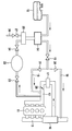
도 1은 연료 탱크 시스템을 통해 연료를 공급받는 과급 내연기관과 함께 연료 탱크 시스템의 구성요소들을 도시한 개략도이다.1 is a schematic diagram illustrating the components of a fuel tank system with a turbocharged internal combustion engine supplied through the fuel tank system.
도 1에 도시된 연료 탱크 시스템은 우선 내연기관(11)에 연료를 공급하기 위한 연료 탱크(10)를 포함한다. 연료는 흡기관(12)을 통해 내연기관(11)으로 공급된다. 연료 탱크(10)로부터 흡기 영역으로 향하는 연료에 대한 직접적인 공급 라인은 도시되어 있지 않다. 배기가스는 배기가스 분기 장치(13)를 통해 내연기관(11)에서 배출된다. 탱크(10)로부터 증발하는 연료는 활성탄 필터(14)에서 포집되어 저장된다. 탱크 통기 밸브(15)의 개방을 통해 저장된 연료 증기는 활성탄 필터로부터 내연기관(11)으로 공급될 수 있다. 내연기관(11)의 흡기 영역(12) 내에는, 내연기관의 효율을 높이도록, 공급되는 신선한 공기를 압축하기 위해 제공되는 터보차저(16)가 배치되어 있다. 압축은 혼합기의 온도를 높이기 때문에, 연료 혼합기가 스로틀 장치(28)를 통해 내연기관(11)으로 공급되기 전에, 과급 공기의 온도를 낮추는 급기 냉각기(17)가 제공된다. 터보차저(16)는 배기가스 분기 장치(13) 내 배기가스 유량을 통해 구동된다. 탱크 통기 밸브(15)를 통한 탱크 통기는, 터보차저(16)의 하류나 급기 냉각기(17)의 상류로 통하는 라인(18) 및 라인(19)을 통해 이루어질 수 있다. 라인(18) 및 라인(19)은 각각 체크 밸브(20, 21)를 구비하고 있다.The fuel tank system shown in FIG. 1 first comprises a
본 발명에 따라, 라인을 통해 내연기관(11)의 과급된 흡기 영역(12)과 연결되는 축압기(22)가 시스템에 제공된다. 흡기 영역(12)과 축압기(22) 사이의 밸브(23)의 개방을 통해 축압기(22)는 과급될 수 있다. 축압기(22)와 나머지 연료 탱크 시스템 사이에 추가 밸브(24)가 제공된다. 상기 밸브(24)의 개방을 통해, 압력은 축압기(22)로부터 연료 탱크 시스템 내로 전달될 수 있다. 연료 탱크 시스템의 상기 구현예에서, 압력은 축압기(22)로부터 활성탄 필터(14)를 통해 연료 탱크 시스템 내로 유입된다. 이를 위해, 주변 공기 공급을 위해 제공된 활성탄 필터(14)의 공급 라인의 영역 내로 통해 있는 라인이 제공된다. 전환 밸브(25)에 의해 라인(26)을 통한 외부 공기 공급과 축압기(22)로부터의 압력의 전달 사이에 전환이 이루어질 수 있다. 그 밖에도, 활성탄 필터 차단 밸브(27)도 제공된다.According to the invention, the
본 발명의 핵심은, 시스템에, 내연기관(11)의 과급된 흡기 영역(12)을 통해 과급되는 축압기(22)가 제공되는 것이다. 압력은 축압기(22)로부터, 특히 연료 탱크(10)와, 활성탄 필터(14)와, 상응하는 라인들로 구성되는 연료 탱크 시스템 내로 전달된다. 상응하는 밸브들의 폐쇄를 통해, 연료 탱크 시스템은 나머지 시스템으로부터 압력 분리된다. 폐쇄된 연료 탱크 시스템 내에 이어지는 압력 특성 곡선이 관찰된다. 상기 특성 곡선에 의해, 연료 탱크 시스템 내에 기밀성 결함이 존재하는지의 여부를 확인할 수 있다. 기밀성 결함이 존재하는 한, 상응하는 결함이 출력될 수 있다. 이 경우, 연료 탱크 시스템 내 압력을 형성하기 위해 연료 탱크 시스템 내에 추가의 능동적 압력원이 요구되지 않는다는 장점이 있다. 오히려, 내연기관(11)의 흡기 영역에서 개시되는 압축이, 연료 탱크 시스템으로 압력을 공급하기 위해, 터보차저(16)를 통해 이용될 수 있다. 이를 위해, 본 발명에 따라, 내연기관(11)의 작동 중에 지정된 방식으로 압력을 임시 저장할 수 있고, 특히 내연기관 작동의 애프트런 시간에 제어되는 방식으로 연료 탱크 시스템으로 전달할 수 있도록, 축압기(22)는 이용된다.The heart of the invention is that the system is provided with an
본 발명에 따르는 방법은 예컨대, 축압기(22)가 엔진 작동 중 밸브(23)의 개방을 통해 내연기관(11)의 흡기관 내에 터보차저(16)를 통해 과급된 영역(12)으로부터 출발하여 최대 압력(pmax)에 이를 때까지 과급되도록 실행될 수 있다. 내연기관 작동의 애프트런 시간에, 밸브(24)의 개방을 통해, 그리고 전환 밸브(25)가 그에 상응하게 스위칭될 시, 탱크 시스템은 축압기(22)로부터 압력을 공급받는다. 이는 바람직하게, 탱크 시스템 내에 진단을 위해 지정된 시작점, 특히 진단 시작점 압력(pdiag)에 도달할 때까지 실행된다. 상기 과정은, 탱크 시스템의 다양한 위치들에 배치될 수 있는 압력 센서로, 또는 예컨대 간접적인 측정 방법들로 모니터링될 수 있다. 이어서, 밸브(24)는 폐쇄된다. 탱크 통기 밸브(15)도 폐쇄되기 때문에, 폐쇄된 연료 탱크 시스템 내 압력은 다소간 유지된다. 각각 시스템 내 압력이 어느 정도로 빠르게 강하되는지에 따라서, 기밀성 결함이 존재하는지의 여부를 추론할 수 있다. 이를 위해, 압력은 바람직하게 사전 설정 가능한 시간(Δt)에 걸쳐 관찰된다. 상기 시간 내에 압력이 사전 설정 가능한 임계값까지 강하하거나, 사전 설정 가능한 임계값보다 높은 압력 강하가 관찰되면, 기밀성 결함 또는 누출이 검출될 수 있다. 임계값은 특히 탱크 시스템 내 압력비에 영향을 미치는 다양한 환경의 영향에 의존하여 계산될 수 있다. 특히, 주면 온도 및/또는 연료 탱크 내온도 및/또는 대기 압력 및/또는 탱크 충전 레벨이 고려될 수 있다.The method according to the invention starts with, for example, the
연료 탱크 시스템 내 압력은 상응하는 압력 센서 값들에 의해 검출될 수 있다. 그 밖에도, 압력에 의존하여 존재하는 다른 변수들을 통해 압력을 관찰할 수 있다. 예컨대 기본적으로, 이를 위해 탱크 시스템 내 온도 특성 곡선의 관찰이 적합한데, 그 이유는 온도가 연료의 가스 방출에 대한 척도이며, 가스 방출은 재차 특히 연료 탱크 내 압력에 의존하기 때문이다.The pressure in the fuel tank system can be detected by corresponding pressure sensor values. In addition, pressure can be observed through other variables that exist depending on the pressure. Basically, for example, observation of the temperature characteristic curve in the tank system is suitable for this, because the temperature is a measure of the gas evolution of the fuel, which in turn depends in particular on the pressure in the fuel tank.
그 밖에도, 추가 축압기(22)를 포함하는 상술된 연료 탱크 시스템으로, 활성탄 필터(14)의 특히 바람직한 세정 또는 재생이 실행될 수 있다. 터보차저(16)로 생성되는, 내연기관(11)의 흡기 영역(12) 내 정압을 통해, 활성탄 필터(14)의 세정 동안 축압기(22) 내에 임시 저장된 압력을 이용함으로써, 탱크 통기 밸브(15)의 특히 균일한 제어가 가능해질 수 있다. 이를 위해, 활성탄 필터(14)는 재생 과정 동안 축압기(22)로부터 압력을 공급받는다. 탱크 통기 밸브(15)를 통해 흐르는 질량 유량은 축압기(22) 내 압력의 정보뿐 아니라, 스로틀 장치(28)와 내연기관(11)의 흡기 밸브들 사이의 흡기관(12) 내 압력의 정보를 통해 계산될 수 있다. 흡기관 압력의 각각의 변화에 따라, 흡기관(12)과 활성탄 필터(14) 사이의 밸브(15)는 다소 넓게 개방되어서, 활성탄 필터(14)로부터 유출되는 세정 가스 또는 재생 가스와 신선한 공기로 이루어진 엔진의 비례하는 충전 비율이 일정하게 설정될 수 있게 된다. 이를 통해, 탱크 통기 동안 엔진 작동에 대한 영향은 활성탄 필터(14)의 각각 상이한 충전을 통해 최소화될 수 있어서, 특히 탱크 통기 과정 동안 자동차의 주행성이 분명하게 향상될 수 있다.In addition, with the above-described fuel tank system including an
Claims (14)
- 내연기관의 과급된 흡기관 영역(12)으로부터 축압기(22)가 충전되고,
- 압력은 축압기(22)로부터 연료 탱크 시스템 내로 전달되며,
- 폐쇄된 연료 탱크 시스템 내에서 압력의 변화 추이가 관찰되며,
- 상기 압력의 변화 추이에 의해, 연료 탱크 시스템 내 누출이 추론되는 것을 특징으로 하는, 기밀성을 모니터링하기 위한 방법.In the method for monitoring the airtightness of the fuel tank system provided for fuel supply of the turbocharged internal combustion engine (11),
The accumulator 22 is charged from the supercharged intake pipe region 12 of the internal combustion engine,
Pressure is transferred from the accumulator 22 into the fuel tank system,
Trends of pressure change are observed in closed fuel tank systems;
A leak in the fuel tank system is inferred by the trend of pressure change.
내연기관(11)의 과급된 흡기 영역(12)을 통해 과급될 수 있는 하나 이상의 축압기(22)가 연료 탱크 시스템에 장착되며, 축압기(22)와 내연기관(11)의 과급된 흡기 영역(12) 사이에는 하나 이상의 밸브(23)가 배치되어 있고 축압기(22)와 나머지 연료 탱크 시스템 사이에는 하나 이상의 추가 밸브(24)가 배치되는 것을 특징으로 하는, 과급 내연기관으로 연료를 공급하기 위한 연료 탱크 시스템.In the fuel tank system for supplying fuel to the turbocharged internal combustion engine (11),
One or more accumulators 22, which can be supercharged through the supercharged intake zone 12 of the internal combustion engine 11, are mounted to the fuel tank system, and the supercharged intake zones of the accumulator 22 and the internal combustion engine 11. At least one valve (23) is arranged between (12) and at least one additional valve (24) is arranged between the accumulator (22) and the remaining fuel tank system. For fuel tank system.
흡착 필터(14)의 세정 시 필터(14)는 축압기(22)로부터 압력을 공급받으며, 이때 축압기(22)는 내연기관(11)의 과급된 흡기 영역(12)을 통해 과급되는 것을 특징으로 하는, 흡착 필터를 재생하는 방법.A method for regenerating the adsorption filter 14 for fuel vapor in the fuel tank system of the turbocharged internal combustion engine 11, wherein the regeneration of the adsorption filter 14 cleans the adsorption filter 14 with ambient air and In the method for regenerating the adsorption filter, which is made by discharging a washing flow in the direction of the intake pipe 12 of (11),
When the adsorption filter 14 is cleaned, the filter 14 receives pressure from the accumulator 22, in which the accumulator 22 is supercharged through the supercharged intake area 12 of the internal combustion engine 11. A method of regenerating an adsorption filter.
Applications Claiming Priority (2)
| Application Number | Priority Date | Filing Date | Title |
|---|---|---|---|
| DE102012219048.1A DE102012219048A1 (en) | 2012-10-18 | 2012-10-18 | Method for monitoring the tightness of a fuel tank system |
| DE102012219048.1 | 2012-10-18 |
Publications (1)
| Publication Number | Publication Date |
|---|---|
| KR20140049936A true KR20140049936A (en) | 2014-04-28 |
Family
ID=50436979
Family Applications (1)
| Application Number | Title | Priority Date | Filing Date |
|---|---|---|---|
| KR1020130122921A KR20140049936A (en) | 2012-10-18 | 2013-10-15 | Method for monitoring the tightness of a fuel tank system |
Country Status (3)
| Country | Link |
|---|---|
| US (1) | US20140109882A1 (en) |
| KR (1) | KR20140049936A (en) |
| DE (1) | DE102012219048A1 (en) |
Cited By (1)
| Publication number | Priority date | Publication date | Assignee | Title |
|---|---|---|---|---|
| KR20200076729A (en) * | 2017-11-14 | 2020-06-29 | 비테스코 테크놀로지스 게엠베하 | Method and device for diagnosing crankcase ventilation line for internal combustion engines |
Families Citing this family (9)
| Publication number | Priority date | Publication date | Assignee | Title |
|---|---|---|---|---|
| GB2533936B (en) | 2015-01-07 | 2017-10-25 | Homeserve Plc | Flow detection device |
| GB201501935D0 (en) | 2015-02-05 | 2015-03-25 | Tooms Moore Consulting Ltd And Trow Consulting Ltd | Water flow analysis |
| US20170114758A1 (en) * | 2015-09-29 | 2017-04-27 | Eagle Actuator Components Gmbh & Co. Kg | Positioning an activated carbon filter in an arrangement for its regeneration |
| DE102015221536A1 (en) * | 2015-11-03 | 2017-05-04 | Volkswagen Aktiengesellschaft | Device and method for tank leak diagnosis |
| USD800591S1 (en) | 2016-03-31 | 2017-10-24 | Homeserve Plc | Flowmeter |
| US10481043B2 (en) * | 2017-09-12 | 2019-11-19 | GM Global Technology Operations LLC | Method for small leak testing of an evaporative emissions system |
| US10968852B2 (en) * | 2018-03-14 | 2021-04-06 | Ford Global Technologies, Llc | Systems and methods for fuel filter diagnostics |
| DE112020003540A5 (en) * | 2019-07-23 | 2022-04-14 | Vitesco Technologies GmbH | Method and device for diagnosing an evaporative emission control system of an internal combustion engine |
| DE102019130300A1 (en) * | 2019-11-11 | 2021-05-12 | Volkswagen Aktiengesellschaft | Tank ventilation system and motor vehicle |
Family Cites Families (4)
| Publication number | Priority date | Publication date | Assignee | Title |
|---|---|---|---|---|
| US4434775A (en) * | 1981-07-21 | 1984-03-06 | Nippondenso Co., Ltd. | Apparatus for controlling pressurized air supply to engines |
| DE4124465C2 (en) | 1991-07-24 | 2002-11-14 | Bosch Gmbh Robert | Tank ventilation system and motor vehicle with such and method and device for checking the functionality of such |
| US6634343B2 (en) * | 2000-12-01 | 2003-10-21 | Denso Corporation | Evaported fuel processor and fault diagnosing apparatus therefor |
| DE10129695A1 (en) * | 2001-06-22 | 2003-01-30 | Bosch Gmbh Robert | Method and device for tank leak diagnosis using a reference measurement method |
-
2012
- 2012-10-18 DE DE102012219048.1A patent/DE102012219048A1/en not_active Withdrawn
-
2013
- 2013-10-15 KR KR1020130122921A patent/KR20140049936A/en not_active Application Discontinuation
- 2013-10-18 US US14/057,228 patent/US20140109882A1/en not_active Abandoned
Cited By (1)
| Publication number | Priority date | Publication date | Assignee | Title |
|---|---|---|---|---|
| KR20200076729A (en) * | 2017-11-14 | 2020-06-29 | 비테스코 테크놀로지스 게엠베하 | Method and device for diagnosing crankcase ventilation line for internal combustion engines |
Also Published As
| Publication number | Publication date |
|---|---|
| US20140109882A1 (en) | 2014-04-24 |
| DE102012219048A1 (en) | 2014-04-24 |
Similar Documents
| Publication | Publication Date | Title |
|---|---|---|
| KR20140049936A (en) | Method for monitoring the tightness of a fuel tank system | |
| CN109715924B (en) | Method and device for checking the functionality of a crank housing exhaust system | |
| RU2620901C2 (en) | Method for operating the engine (versions) and carter ventilation system | |
| RU2620906C2 (en) | Method for operating the engine (versions) and carter ventilation system | |
| RU2580607C2 (en) | Engine operation method and crankcase ventilation system therefor | |
| CN107532544B (en) | The method of the leakage of internal combustion engine and for identification crankcase ventilation system and/or fuel tank vent system | |
| RU2620911C2 (en) | Engine operating method (versions) | |
| US9551304B2 (en) | Tank venting system and method for diagnosing same | |
| US7963150B2 (en) | Method to test for a leak in a fuel tank system | |
| CN103109067B (en) | For diagnosing equipment and the method for the leakage of fuel tank | |
| KR20200076729A (en) | Method and device for diagnosing crankcase ventilation line for internal combustion engines | |
| US10851735B2 (en) | Fault diagnosis device | |
| CN104471231A (en) | Turbocharged engine purge flow monitor diagnostic | |
| CN105593480A (en) | Method for detecting a leak in a crankcase breather | |
| CN104685172A (en) | Method and device for operating an internal combustion engine | |
| US20210348532A1 (en) | Method And Device For Checking The Functionality Of A Crankcase Ventilation System Of An Internal Combustion Engine | |
| JP2011518977A (en) | Method and apparatus for diagnosing functional state of fuel vapor intermediate storage device | |
| US20170260930A1 (en) | Leakage Diagnosis In A Fuel Tank System | |
| US8365706B2 (en) | Method and device for testing the tightness of a fuel tank of an internal combustion engine | |
| US20150330349A1 (en) | Method and apparatus for detecting leakage of fuel evaporative gas | |
| US11073112B2 (en) | Evaporative emission control system for a vehicle | |
| CN107886593B (en) | Calculation method for fuel tank evaporative emission leakage diagnosis and detection strategy | |
| CN107636294B (en) | Tank ventilation device and method for diagnosing a tank ventilation device | |
| KR20170025156A (en) | Method and device for diagnosing leak of fuel system in vehicle | |
| US11118958B2 (en) | System for determining a filling level in a fuel tank |
Legal Events
| Date | Code | Title | Description |
|---|---|---|---|
| WITN | Application deemed withdrawn, e.g. because no request for examination was filed or no examination fee was paid |