KR20140049329A - Drain trap - Google Patents
Drain trap Download PDFInfo
- Publication number
- KR20140049329A KR20140049329A KR1020120115455A KR20120115455A KR20140049329A KR 20140049329 A KR20140049329 A KR 20140049329A KR 1020120115455 A KR1020120115455 A KR 1020120115455A KR 20120115455 A KR20120115455 A KR 20120115455A KR 20140049329 A KR20140049329 A KR 20140049329A
- Authority
- KR
- South Korea
- Prior art keywords
- opening
- closing
- base panel
- water
- sump
- Prior art date
Links
Images


Classifications
-
- E—FIXED CONSTRUCTIONS
- E03—WATER SUPPLY; SEWERAGE
- E03F—SEWERS; CESSPOOLS
- E03F5/00—Sewerage structures
- E03F5/04—Gullies inlets, road sinks, floor drains with or without odour seals or sediment traps
- E03F5/0407—Floor drains for indoor use
-
- E—FIXED CONSTRUCTIONS
- E03—WATER SUPPLY; SEWERAGE
- E03C—DOMESTIC PLUMBING INSTALLATIONS FOR FRESH WATER OR WASTE WATER; SINKS
- E03C1/00—Domestic plumbing installations for fresh water or waste water; Sinks
- E03C1/12—Plumbing installations for waste water; Basins or fountains connected thereto; Sinks
- E03C1/122—Pipe-line systems for waste water in building
-
- E—FIXED CONSTRUCTIONS
- E03—WATER SUPPLY; SEWERAGE
- E03F—SEWERS; CESSPOOLS
- E03F5/00—Sewerage structures
- E03F5/04—Gullies inlets, road sinks, floor drains with or without odour seals or sediment traps
- E03F5/041—Accessories therefor
-
- F—MECHANICAL ENGINEERING; LIGHTING; HEATING; WEAPONS; BLASTING
- F16—ENGINEERING ELEMENTS AND UNITS; GENERAL MEASURES FOR PRODUCING AND MAINTAINING EFFECTIVE FUNCTIONING OF MACHINES OR INSTALLATIONS; THERMAL INSULATION IN GENERAL
- F16K—VALVES; TAPS; COCKS; ACTUATING-FLOATS; DEVICES FOR VENTING OR AERATING
- F16K15/00—Check valves
- F16K15/02—Check valves with guided rigid valve members
- F16K15/03—Check valves with guided rigid valve members with a hinged closure member or with a pivoted closure member
-
- E—FIXED CONSTRUCTIONS
- E03—WATER SUPPLY; SEWERAGE
- E03F—SEWERS; CESSPOOLS
- E03F5/00—Sewerage structures
- E03F5/04—Gullies inlets, road sinks, floor drains with or without odour seals or sediment traps
- E03F2005/0416—Gullies inlets, road sinks, floor drains with or without odour seals or sediment traps with an odour seal
-
- Y—GENERAL TAGGING OF NEW TECHNOLOGICAL DEVELOPMENTS; GENERAL TAGGING OF CROSS-SECTIONAL TECHNOLOGIES SPANNING OVER SEVERAL SECTIONS OF THE IPC; TECHNICAL SUBJECTS COVERED BY FORMER USPC CROSS-REFERENCE ART COLLECTIONS [XRACs] AND DIGESTS
- Y10—TECHNICAL SUBJECTS COVERED BY FORMER USPC
- Y10S—TECHNICAL SUBJECTS COVERED BY FORMER USPC CROSS-REFERENCE ART COLLECTIONS [XRACs] AND DIGESTS
- Y10S4/00—Baths, closets, sinks, and spittoons
- Y10S4/07—House plumbing fittings
Abstract
Description
본 발명은 세탁실에 설치되는 배수트랩에 관한 것으로, 구체적으로는 바닥 위로 노출된 걸름망에는 세탁기 호스를 꽂아 사용하도록 하고, 바닥에 매립된 집수통에는 하나 이상의 하수관이 연결되도록 하되, 걸름망 하부의 나팔관의 하단을 통과하는 세탁수가 선회하면서 오버플로우 컵으로 배출되도록 하여 물 빠짐이 원활하고, 상기 하수관이 연결된 집수통의 연결구를 개폐하여 악취 또는 오수의 역류를 보다 안전하게 차단할 수 있도록 한 세탁실 설치용 배수트랩에 관한 것이다.
The present invention relates to a drain trap that is installed in the laundry room, specifically to be used by plugging the washing machine hose to the strainer net exposed on the floor, one or more sewage pipes are connected to the sump can be buried in the bottom, Regarding the drainage trap for laundry room installation, the washing water passing through the lower part is discharged to the overflow cup while smoothly draining the water, and by opening and closing the connection port of the sump connected to the sewage pipe to more effectively block odor or backflow of sewage. will be.
일반적으로 배수트랩은 베란다, 화장실, 목욕탕 또는 세탁실 등의 실내 바닥에 설치되는 것으로서, 생활 오수는 하수관으로 배출하면서 이물질은 걸러내도록 하고, 하수관으로부터 실내로 악취 및 오수가 역류하는 것을 방지하도록 형성되어 있다. 이 중에서도 특히 세탁실에 설치되는 배수트랩은 세탁기 호스를 꽂아 사용하도록 형성된 것이 제공되어 있다.In general, the drain trap is installed on the interior floor of a porch, toilet, bathroom or laundry room, and it is formed to filter out foreign substances while discharging the sewage into the sewage pipe, and to prevent odor and sewage from flowing back from the sewer pipe to the room. . Among them, in particular, the drain trap installed in the laundry room is provided to be used by inserting a washing machine hose.
이와 같은 종래 세탁실 설치용 배수트랩의 구조는 도 1에 도시된 바와 같이 바닥 표면에 매립되면서 물이 모이도록 요입된 공간의 중앙에 결합구가 하부로 돌출 형성되고, 상기 결합구 내주연에는 단턱이 형성된 베이스 패널(10); 바닥 내부에 매립된 상태에서 상부는 상기 베이스 패널의 결합구와 연결되고, 측부는 바닥에 매립된 하나 이상의 하수관과 연결하기 위한 연결구가 형성된 집수통(20); 상기 베이스 패널의 단턱에 안착된 상태로 상기 집수통 내부에 설치되고, 일정높이의 상부 측면에는 물이 넘쳐 상기 집수통으로 배출되도록 배수구가 형성된 오버플로우 컵(30); 상기 오버플로우 컵 위에 안착되고, 하단이 상기 오버플로우 컵의 배수구 하부에 잠기도록 설치되어, 상기 베이스 패널로 모인 물이 하단을 경유하여 상기 배수구로 배출되도록 형성된 나팔관(40); 및 상기 베이스 패널의 결합구에 결합되어 상기 나팔관으로 유입되는 이물질을 걸러내도록 하되, 중앙에는 세탁기 호스를 끼울 수 있도록 설치구가 형성된 걸름망(50);으로 구성된다.
Such a structure of a conventional laundry room drain trap is formed in the center of the space concaved to collect water while being buried in the floor surface as shown in Figure 1, the coupling is formed in the inner periphery is stepped
그러나 이와 같은 구성의 배수트랩은 세탁기 호스를 걸름망의 설치구에 끼운 후 세탁수를 배출시킬 때 갑자기 배출되는 세탁수가 나팔관의 하단을 통해 오버플로우 컵으로 원활하게 빠져나가지 못하고 정체되면서 걸름망 위로 역류하는 현상이 빈번하게 발생한다. 이와 같은 현상이 발생하면 세탁수가 세탁실 바닥으로 넘치기 때문에 세탁 후 세탁실 바닥을 청소해야 하는 등 불편함을 초래하여 상기 세탁기 호스를 끼워 사용하는 목적을 무색하게 한다. 또한, 상기 나팔관 하단에 정체되었던 물이 한꺼번에 오버플로우 컵으로 빠져나가면 울컥하면서 소리가 발생하게 되는데, 이와 같은 현상은 세탁수가 다 배출될 때까지 반복해서 일어나면서 소음을 발생시킬 뿐만 아니라, 배수 시간을 상당히 지연시키는 문제가 발생한다.
However, this type of drain trap is a phenomenon in which the washing water discharged suddenly when draining the washing water after inserting the washing machine hose into the mounting hole of the strainer does not flow out smoothly into the overflow cup through the bottom of the fallopian tube and stagnates back into the strainer. This happens frequently. When such a phenomenon occurs, washing water overflows to the laundry room floor, resulting in inconvenience such as cleaning the laundry room floor after washing, thereby making the purpose of inserting the washing machine hose uncolored. In addition, when the water stagnated at the bottom of the fallopian tube escapes to the overflow cup all at once, it generates a crying sound. Such a phenomenon occurs repeatedly until the wash water is discharged, generating noise, and draining time. There is a significant delay.
한편, 상기 집수통의 측면에는 상기 하수관과 연결되어 오버플로우 컵으로부터 배출되는 물을 배출시키기 위한 연결구가 형성되는데, 종래에는 상기 하수관으로부터 발생하는 악취나 오수가 상기 연결구를 통해 집수통 내부로 유입되는 문제점이 있다. 이와 같이 상기 집수통으로 유입된 악취나 오수는 상기 베이스 패널과 집수통의 연결부분을 통해 실내로 유입되기도 하고, 역류하는 수압이 높을 경우 오버플로우 컵과 나팔관을 통해 실내로 유입되기도 한다.
On the other hand, the side surface of the sump is connected to the sewage pipe is formed for discharging the water discharged from the overflow cup, conventionally odor or sewage generated from the sewage pipe is introduced into the sump through the connector There is a problem. As described above, the odor or filthy water introduced into the sump may be introduced into the room through the connection portion between the base panel and the sump, or may be introduced into the room through the overflow cup and the fallopian tube when the back pressure is high.
본 발명은 바닥 위로 노출된 걸름망에는 세탁기 호스를 꽂아 사용하도록 하고, 바닥에 매립된 집수통에는 하나 이상의 하수관이 연결되도록 하되, 걸름망 하부의 나팔관의 하단을 통과하는 세탁수가 선회하면서 오버플로우 컵으로 배출되도록 하여 물 빠짐이 원활하고, 상기 하수관이 연결된 집수통의 연결구를 개폐하여 악취 또는 오수의 역류를 보다 안전하게 차단할 수 있도록 한 세탁실 설치용 배수트랩을 제공하려는 것이다.
The present invention is to be used to plug the washing machine hose to the net exposed to the floor, one or more sewage pipes are connected to the sump can be buried in the bottom, while the wash water passing through the lower end of the fallopian tube of the bottom of the net is discharged to the overflow cup It is to provide a drainage trap for the laundry room installation so that water can be smoothly drained, and opening and closing the connection port of the sump pipe connected to the sewer pipe to more safely block the backflow of odor or filthy water.
본 발명은 세탁실에 설치되어 세탁기 호스를 꽂아 사용할 수 있도록 형성된 세탁실 설치용 배수트랩에 있어서, 바닥 표면에 매립되면서 물이 모이도록 요입된 공간의 중앙에는 하부로 돌출된 결합구가 형성되고, 상기 결합구 내주연에는 단턱이 형성된 베이스 패널; 바닥 내부에 매립된 상태에서 상부에는 상기 베이스 패널의 결합구와 연결되고, 측부에는 바닥에 매립된 하나 이상의 하수관과 연결되도록 하되, 상기 하수관과 연결되는 측부에는 개폐공간이 외측으로 돌출 형성되고, 상기 개폐공간으로부터 하수관을 연결하기 위한 연결구가 돌출 형성된 집수통; 상기 집수통의 개폐공간에 끼워 결합하기 위한 개폐틀과 상기 개폐틀의 외측 상부 양측에 축 결합하여 자중에 의해 닫히면서 내부의 물은 배출시키고 외부의 악취와 오수의 역류를 차단하는 개폐판으로 형성된 개폐유닛; 상기 베이스 패널의 단턱에 상단 테두리가 안착된 상태로 상기 집수통 내부에 설치되고, 일정높이의 상부 측면에는 물이 넘쳐 상기 집수통으로 배출되도록 배수구가 형성된 오버플로우 컵; 상기 오버플로우 컵 위에 상단 테두리가 안착된 상태에서 하단이 상기 오버플로우 컵의 바닥에 닿도록 하부로 연장 형성되고, 상기 연장된 하부의 측면에는 하나 이상의 선회 유도구를 외측으로 돌출 형성하되, 상기 돌출된 선회 유도구의 끝단은 상기 오버플로우 컵의 내측면으로부터 이격되어, 상기 베이스 패널로 모인 물이 상기 선회 유도구를 통해 상기 오버플로우 컵으로 통과하면서 일 방향으로 선회하도록 형성된 나팔관; 및 상기 베이스 패널의 결합구에 결합되어 상기 나팔관으로 출입을 차단하되, 중앙에는 세탁기 호스를 끼울 수 있도록 설치구가 형성된 걸름망;으로 구성된다.The present invention is a drainage trap for a laundry room installation is installed in the laundry room to be plugged into the washing machine hose, the coupler is formed in the center of the space concaved to collect water while being buried in the bottom surface is formed, the coupler A base panel having a stepped portion formed on an inner circumference; In the state buried inside the bottom is connected to the coupling hole of the base panel on the upper side, and connected to one or more sewage pipes embedded in the bottom, the side connected to the sewer pipe opening and closing space protruding to the outside, A sump with a connector for projecting a sewer pipe from the space; Opening and closing frame for coupling to the opening and closing space of the sump and the shaft is coupled to both sides of the outer upper side of the opening and closing by self-weight is formed as an opening and closing plate to discharge the internal water and block the backflow of odor and sewage outside Opening and closing unit; An overflow cup installed inside the sump in a state where an upper edge is seated on the stepped portion of the base panel, and an upper side of a predetermined height overflowing water to discharge the sump into the sump; The lower end is formed to extend to the bottom to reach the bottom of the overflow cup in a state that the upper edge is seated on the overflow cup, the one side of the extended lower protruding to form one or more turning guides to the outside, the protrusion An end of the revolving induction hole is spaced apart from an inner side surface of the overflow cup so that the water collected in the base panel pivots in one direction while passing through the revolving induction port to the overflow cup; And it is coupled to the coupling hole of the base panel to block the entrance to the fallopian tube, the center of the strainer is formed so that the fitting hole can be fitted into the washer hose;
상기 개폐유닛의 개폐틀은 외측 상부에서 하부로 일정한 경사가 형성된다.The opening and closing frame of the opening and closing unit is formed with a constant inclination from the outer top to the bottom.
상기 개폐유닛의 개폐틀 또는 개폐판의 상호 접하는 테두리 면에 결합되는 밀폐용 패킹;을 포함하여 구성된다.It is configured to include; sealing for sealing coupled to the border surface of the opening and closing unit or the opening and closing plate of the opening and closing unit.
상기 나팔관은 내측면에 형성되고, 상기 나팔관의 내부 중심에 임의의 관을 끼워 고정하면서 상기 관 주변으로 물이 빠지도록 형성된 하나 이상의 고정 리브;를 포함하여 구성된다.The fallopian tube is formed on the inner side, one or more fixing ribs formed so as to drain the water around the tube while fixing any tube in the inner center of the fallopian tube.
상기 걸름망은 상기 설치구에 결합되고, 상기 세탁기 호스를 끼워 연결하기 위한 연결부재;를 포함하여 구성된다.The strainer is coupled to the installation port, and comprises a connecting member for connecting the washing machine hose.
상기 베이스 패널의 결합구 상측 내주연에는 레일 홈이 형성된 상태에서 상기 레일 홈 양측에 절개구가 형성되고, 상기 걸름망의 양측 테두리에는 상기 절개구를 통해 레일 홈에 끼워지도록 고정돌기가 형성된 상태에서 상기 걸름망 상부에는 상기 걸름망을 돌리기 위한 손잡이 돌기가 형성된다.
In the inner circumference of the upper side of the coupling hole of the base panel, a cutout is formed at both sides of the rail groove in a state in which a rail groove is formed, and in a state in which a fixing protrusion is formed at both edges of the strainer to fit into the rail groove through the cutout. The upper part of the strainer is formed with a handle projection for turning the strainer.
본 발명의 세타실 설치용 배수트랩에 의하면 걸름망에 세탁기 호스를 꽂은 상태로 많은 량의 세탁수를 한꺼번에 배출시키더라도 상기 나팔관 하부의 선회 유도구를 통해 세탁수가 선회하면서 배출되어 세탁수의 정체를 방지하기 때문에 세탁수가 세탁실 바닥으로 넘치는 것을 방지하는 효과와 아울러, 상기 집수통의 개폐공간에 설치된 개폐유닛이 오수의 배출은 원활하게 하면서 악취와 오수의 역류를 차단하기 때문에 오수와 악취의 역류로부터 더욱 안전해지는 효과가 있다.
According to the drainage trap for theta room installation according to the present invention, even if a large amount of washing water is discharged at once while the washing machine hose is plugged into the strainer, the washing water is discharged through the turning induction hole under the fallopian tube to prevent stagnation of the washing water. Therefore, the washing water is prevented from overflowing to the laundry room floor, and the opening / closing unit installed in the opening / closing space of the sump can smoothly discharge the effluent and blocks the odor and the backflow of the filthy water, thereby making it safer from the backflow of the filthy water and the odor. It works.
도 1은 종래 세탁실 설치용 배수트랩을 도시한 측단면도.
도 2는 본 발명이 적용된 세탁실 설치용 배수트랩을 도시한 측단면도.
도 3은 본 발명이 적용된 세탁실 설치용 배수트랩을 도시한 분해 사시도.
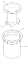
도 4는 본 발명이 적용된 세탁실 설치용 배수트랩의 집수통과 개폐유닛을 도시한 부분 절개 사시도.
도 5는 본 발명이 적용된 세탁실 설치용 배수트랩의 개폐유닛을 도시한 분해 사시도.
도 6은 본 발명이 적용된 세탁실 설치용 배수트랩의 개폐유닛을 도시한 측단면도.
도 7은 본 발명이 적용된 세탁실 설치용 배수트랩의 오버플로우 컵과 나팔관을 도시한 분해 사시도.
도 8은 본 발명이 적용된 세탁실 설치용 배수트랩의 오버플로우 컵과 나팔관을 도시한 평단면도.
도 9는 본 발명이 적용된 세탁실 설치용 배수트랩의 오버플로우 컵과 나팔관을 도시한 측단면도.
도 10은 본 발명이 적용된 세탁실 설치용 배수트랩의 베이스 패널과 걸름망을 도시한 분해 사시도.
도 11은 본 발명이 적용된 세탁실 설치용 배수트랩의 베이스 패널과 걸름망을 도시한 측단면도.1 is a side cross-sectional view showing a drain trap for a conventional laundry room installation.
Figure 2 is a side sectional view showing a drain trap for a laundry room installation to which the present invention is applied.
Figure 3 is an exploded perspective view showing a drain trap for laundry room installation to which the present invention is applied.
Figure 4 is a partial cutaway perspective view showing a water container and the opening and closing unit of the drain trap for laundry room installation to which the present invention is applied.
Figure 5 is an exploded perspective view showing the opening and closing unit of the drain trap for laundry room installation to which the present invention is applied.
Figure 6 is a side cross-sectional view showing the opening and closing unit of the drain trap for laundry room installation to which the present invention is applied.
Figure 7 is an exploded perspective view showing the overflow cup and fallopian tube of the drain trap for laundry room installation to which the present invention is applied.
Figure 8 is a cross-sectional view showing the overflow cup and fallopian tube of the drain trap for laundry room installation to which the present invention is applied.
Figure 9 is a side cross-sectional view showing an overflow cup and fallopian tube of the drain trap for laundry room installation to which the present invention is applied.
Figure 10 is an exploded perspective view showing a base panel and the strainer of the drain trap for laundry room installation to which the present invention is applied.
Figure 11 is a side cross-sectional view showing a base panel and the strainer of the drain trap for laundry room installation to which the present invention is applied.
본 발명의 바람직한 실시 예를 첨부된 도면에 의거하여 구체적으로 살펴본다.
Preferred embodiments of the present invention will now be described in detail with reference to the accompanying drawings.
본 발명의 세탁실 설치용 배수트랩은 도 2 내지 도 11에 도시된 바와 같이 바닥 표면에 매립되는 베이스 패널(100), 바닥 내부에 매립된 상태에서 측부에는 개폐공간(210)이 외측으로 돌출 형성된 집수통(200), 상기 집수통의 개폐공간에 끼워 결합하기 위한 개폐유닛(300), 상기 베이스 패널의 단턱에 상단 테두리가 안착된 상태로 상기 집수통 내부에 설치되는 오버플로우 컵(400), 상기 오버플로우 컵 위에 상단 테두리가 안착된 상태에서 하단에 하나 이상의 선회 유도구(510)가 형성된 나팔관(500) 및 상기 베이스 패널의 결합구에 결합되면서 세탁기 호스를 끼울 수 있도록 설치구(610)가 형성된 걸름망(600)을 포함하여 구성된다.
Drain trap for laundry room installation of the present invention, the
상기 베이스 패널(100)은 세탁실의 바닥 표면에 매립되면서 물이 모이도록 요입된 공간의 중앙에는 하부로 돌출된 결합구(110)가 형성되고, 상기 결합구(110) 내주연에는 단턱(120)이 형성된된다. 상기 결합구(110) 외면에는 상기 집수통(200)이 결합되고, 상기 결합구(110) 내부의 단턱(120)에는 상기 오버플로우 컵(400)이 안착되며, 그 위로 상기 나팔관(500) 및 걸름망(600)이 올려진다. The
상기 베이스 패널(100)의 결합구(110)에는 상기 걸름망(600)을 끼워 고정하도록 함으로써, 역류하는 수압에 의해 오버플로우 컵(400)과 나팔관(500) 및 걸름망(600)이 들리거나 빠지지 않도록 하는데, 실시 예로서 상기 베이스 패널(100)의 결합구(110) 상측 내주연에는 레일 홈(130)을 형성하고, 상기 레일 홈(130) 양측에는 위로 개방되게 하는 절개구(140)를 형성하여 상기 걸름망(600) 양측에 돌출된 고정돌기(610)를 절개구(140)에 끼운 후 레일 홈(130)을 따라 회전시켜 고정할 수 있도록 한다.
By fitting the
상기 집수통(200)은 바닥 내부에 매립된 상태에서 상부에는 상기 베이스 패널(100)의 결합구(110)와 연결되고, 측부에는 바닥에 매립된 하나 이상의 하수관과 연결되도록 하되, 상기 하수관과 연결되는 측부에는 개폐공간(210)이 외측으로 돌출 형성되고, 상기 개폐공간(210)으로부터 하수관을 연결하기 위한 연결구(220)가 돌출 형성된다. 따라서 상기 집수통(200)은 상기 개폐유닛(300)을 내부로부터 개폐공간(210)으로 밀어 끼워 설치하게 된다. 이때 상기 개폐공간(210)은 사각 박스 형태의 공간으로 이루어지도록 하는 것이 바람직하고 상기 개폐공간(210)의 전방에 형성되는 연결구(220)는 원통 형태로 형성한다.
The
상기 개폐유닛(300)은 상기 집수통(200)의 개폐공간(210)에 끼워 결합하기 위한 개폐틀(310)과 상기 개폐틀(310)의 외측 상부 양측에 축 결합하여 자중에 의해 닫히면서 내부의 물은 배출시키고 외부의 악취와 오수의 역류를 차단하는 개폐판(320)으로 형성된다. 즉, 상기 개폐판(320)이 개폐틀(310)의 외측에서 아래로부터 위로 열리도록 하여, 개폐판(320)은 자중에 의해 항상 닫힌 상태를 유지하도록 한다. 따라서 상기 개폐유닛(300)은 하수관으로부터 악취가 역류하는 것을 1차적으로 방지하고, 하수관으로부터 오수가 역류하더라도 개폐판(320)이 열리지 않기 때문에 오수의 역류를 동시에 방지할 수 있다. 이때, 세탁실에서 버려진 물이 집수통(200)으로 모이면 집수통(200) 내부의 수압에 의해 개폐판(320)이 열리면서 세탁수는 원활하게 배출되는 것이다.The opening and
상기 개폐유닛(300)은 실시 예로서 도 6에 도시된 바와 같이 상기 개폐틀(310)이 외측 상부에서 하부로 일정한 경사가 형성되도록 하여 개폐판(320)이 개폐틀(310)에 긴밀하게 밀착된 상태를 유지하도록 한다.6, the opening and
또한, 상기 개폐유닛(300)의 개폐틀(310) 또는 개폐판(320)의 상호 접하는 테두리 면에는 밀폐용 패킹(330)을 결합하여 기밀성을 더욱 높인다.
In addition, the
상기 오버플로우 컵(400)은 상기 베이스 패널(100)의 단턱(120)에 상단 테두리가 안착된 상태로 상기 집수통(200) 내부에 설치되고, 일정높이의 상부 측면에는 물이 넘쳐 상기 집수통으로 배출되도록 배수구(410)가 형성된다. 따라서 상기 오버플로우 컵(400)은 내부에 일정량의 물을 항상 담아둘 수 있고, 그 이상의 물이 유입되면 상기 배수구(410)를 통해 넘쳐 외부로 배출됨으로써 상기 집수통(200)으로 배출되는 것이다.
The
상기 나팔관(500)은 상기 오버플로우 컵(400) 위에 상단 테두리가 안착된 상태에서 하단이 상기 오버플로우 컵(400)의 바닥에 닿도록 하부로 연장 형성되고, 상기 연장된 하부의 측면에는 하나 이상의 선회 유도구(510)를 외측으로 돌출 형성하되, 상기 돌출된 선회 유도구(510)의 끝단은 상기 오버플로우 컵(400)의 내측면으로부터 이격되어, 상기 베이스 패널(100)로 모인 물이 상기 선회 유도구(510)를 통해 상기 오버플로우 컵(400)으로 통과하면서 일 방향으로 선회하도록 형성된다. 즉, 상기 선회 유도구(510)는 도 8에 도시된 바와 같이 나팔관(500)으로 유입된 물이 나팔관(500) 하부를 통해 오버플로우 컵(400)으로 빠져나가는 과정에서 물이 한 방향으로 회전하도록 흐름을 유도하는 것이다. 이때, 상기 선회 유도구(510)는 실시 예로서 도 8에 도시된 바와 같이 상기 나팔관(500)의 측면으로부터 곡선 형태로 돌출되도록 형성하는 것이 바람직하나, 물이 회전할 수 있는 범위에서 직선 형태로 돌출되게 형성하여도 무방하다. 또한, 상기 선회 유도구(510)는 단면이 사각 형태로 형성하면서 하부면이 개방되도록 하는 것이 바람직하나, 단면을 하부면이 개방된 반원 형태로 형성하여도 무방하다.The
이와 같은 나팔관(500)은 상부가 호퍼 형태로 벌어져 상기 오버플로우 컵(400)의 상부를 커버하고, 하부는 상기 오버플로우 컵(400)의 지름보다 작게 형성된다. 따라서 상기 나팔관(500)은 상기 오버플로우 컵(400)의 상부를 막고 있고 하단은 오버플로우 컵(400)에 담긴 물에 잠긴 상태이므로 상기 배수구(410)를 통해 악취가 역류하더라도, 실내로 유입하는 것을 차단한다.The
한편, 상기 나팔관(500)의 내측면에는 하나 이상의 고정 리브(520)가 형성되는데, 상기 고정 리브(520)는 상기 나팔관(500)의 내부 중심에 임의의 관을 끼워 고정하면서 상기 관 주변으로 물이 빠지도록 형성된다. 상기 임의의 관은 세탁기 호스가 될 수 있고, 세탁기 호스를 연결하기 위한 연결관이 될 수 있다.
On the other hand, the inner surface of the
상기 걸름망(600)은 상기 베이스 패널(100)의 결합구(110)에 결합되어 상기 나팔관(500)을 차단하되, 중앙에는 세탁기 호스를 끼울 수 있도록 설치구(610)가 형성된다. 즉, 상기 걸름망(600)은 세탁기 호스를 끼워 세탁수가 세탁실 바닥에 흐르지 않고 바로 나팔관(500)을 통해 배출되도록 하는 한편, 오수나 악취가 세탁실 위로 올라오지 않도록 차단하는 것이다.The
이때, 상기 걸름망(600)은 상기 설치구(610)에 결합하여 상기 세탁기 호스를 보다 편리하게 끼워 연결하기 위한 파이프 형태의 연결부재(620)를 포함하여 구성된다. 상기 연결부재(620)은 일측으로 꺾인 형태로 형성하여도 무방하고 상기 걸름망으로부터 회전할 수 있도록 하여도 무방하다.At this time, the
한편, 상기 걸름망(600)은 앞서 설명한 바와 같이 상기 베이스 패널(100)의 결합구(110)에 고정 설치하는 것이 바람직한데, 이를 위해서 상기 걸름망(600)의 양측 테두리에는 상기 절개구(140)를 통해 레일 홈(130)에 끼워지도록 고정돌기(630)가 형성되고, 상기 걸름망(600) 상부에는 상기 걸름망(600)을 돌리기 위한 손잡이 돌기(640)가 형성된다. 따라서 상기 걸름망(600)의 고정돌기(630)를 베이스 패널(100)의 절개구(140)에 맞춰 올려놓은 상태에서 상기 손잡이 돌기(640)를 잡고 일측으로 돌리면 상기 고정돌기(630)가 레일 홈(130)에 끼워져 빠지지 않는 것이다.
On the other hand, the
이와 같은 본 발명의 구성에 의하면 상기 걸름망(600)에 세탁기 호스를 꽂은 상태로 많은 량의 세탁수를 한꺼번에 배출시키더라도 상기 나팔관(500) 하부의 선회 유도구(510)를 통해 세탁수가 선회하면서 배출되어 세탁수의 정체를 방지하기 때문에 세탁수가 세탁실 바닥으로 넘치는 것을 막고, 상기 집수통(200)의 개폐공간(210)에 설치된 개폐유닛(300)이 오수의 배출은 원활하게 하면서 악취와 오수의 역류를 차단하기 때문에 오수와 악취의 역류로부터 더욱 안전하게 보호할 수 있는 것이다.
According to the configuration of the present invention as described above, even when the washing machine is plugged into the
100: 베이스 패널 110: 결합구
120: 단턱 130: 레일 홈
140: 절개구
200: 집수통 210: 개폐공간
220: 연결구
300: 개폐유닛 310: 개폐틀
320: 개폐판
400: 오버플로 컵 410: 배수구
500: 나팔관 510: 선회 유도구
520: 고정 리브
600: 걸름망 610: 설치구
620: 연결부재 630: 고정돌기
640: 손잡이 돌기100: Base panel 110: Coupling port
120: step 130: rail groove
140: incision
200: reservoir 210: opening and closing space
220: connector
300: opening and closing unit 310: opening and closing frame
320: opening and closing board
400: overflow cup 410: drain
500: fallopian tube 510: turning guide
520: fixed rib
600: strainer 610: mounting holes
620: connecting member 630: fixing protrusion
640: turning the handle
Claims (6)
바닥 표면에 매립되면서 물이 모이도록 요입된 공간의 중앙에는 하부로 돌출된 결합구가 형성되고, 상기 결합구 내주연에는 단턱이 형성된 베이스 패널;
바닥 내부에 매립된 상태에서 상부에는 상기 베이스 패널의 결합구와 연결되고, 측부에는 바닥에 매립된 하나 이상의 하수관과 연결되도록 하되, 상기 하수관과 연결되는 측부에는 개폐공간이 외측으로 돌출 형성되고, 상기 개폐공간으로부터 하수관을 연결하기 위한 연결구가 돌출 형성된 집수통;
상기 집수통의 개폐공간에 끼워 결합하기 위한 개폐틀과 상기 개폐틀의 외측 상부 양측에 축 결합하여 자중에 의해 닫히면서 내부의 물은 배출시키고 외부의 악취와 오수의 역류를 차단하는 개폐판으로 형성된 개폐유닛;
상기 베이스 패널의 단턱에 상단 테두리가 안착된 상태로 상기 집수통 내부에 설치되고, 일정높이의 상부 측면에는 물이 넘쳐 상기 집수통으로 배출되도록 배수구가 형성된 오버플로우 컵;
상기 오버플로우 컵 위에 상단 테두리가 안착된 상태에서 하단이 상기 오버플로우 컵의 바닥에 닿도록 하부로 연장 형성되고, 상기 연장된 하부의 측면에는 하나 이상의 선회 유도구를 외측으로 돌출 형성하되, 상기 돌출된 선회 유도구의 끝단은 상기 오버플로우 컵의 내측면으로부터 이격되어, 상기 베이스 패널로 모인 물이 상기 선회 유도구를 통해 상기 오버플로우 컵으로 통과하면서 일 방향으로 선회하도록 형성된 나팔관; 및
상기 베이스 패널의 결합구에 결합되어 상기 나팔관으로 출입을 차단하되, 중앙에는 세탁기 호스를 끼울 수 있도록 설치구가 형성된 걸름망;으로 구성된 것을 특징으로 하는 세탁실 설치용 배수트랩.
In the laundry room installation drain trap formed in the laundry room to be plugged into the washing machine hose,
A base panel having a coupler protruding downward from a center of the space confined to the water while being embedded on a bottom surface, and having a stepped portion formed at an inner circumference of the coupler;
In the state buried inside the bottom is connected to the coupling hole of the base panel on the upper side, and connected to one or more sewage pipes embedded in the bottom, the side connected to the sewer pipe opening and closing space protruding to the outside, A sump with a protruding connector for connecting the sewer pipe from the space;
Opening and closing frame for coupling to the opening and closing space of the sump and the shaft is coupled to both sides of the outer upper side of the opening and closing by self-weight is formed as an opening and closing plate to discharge the internal water and block the backflow of odor and sewage outside Opening and closing unit;
An overflow cup installed inside the sump in a state where an upper edge is seated on the stepped portion of the base panel, and an upper side of a predetermined height overflowing water to discharge the sump into the sump;
The lower end is formed to extend to the bottom to reach the bottom of the overflow cup in a state that the upper edge is seated on the overflow cup, the one side of the extended lower protruding to form one or more turning guides to the outside, the protrusion An end of the revolving induction hole is spaced apart from an inner side surface of the overflow cup so that the water collected in the base panel pivots in one direction while passing through the revolving induction port to the overflow cup; And
It is coupled to the coupling hole of the base panel to block the entrance to the fallopian tube, in the center of the trapping net formed with an installation port so as to fit the washing machine hose; Drain trap for the laundry room installation, characterized in that consisting of.
The drain trap for laundry room installation according to claim 1, wherein the opening / closing frame of the opening / closing unit has a predetermined inclination from the outer upper part to the lower part.
The drain trap for a laundry room installation of claim 1, further comprising: a sealing packing coupled to a border surface of the opening / closing unit or the opening / closing plate.
내측면에 형성되고, 상기 나팔관의 내부 중심에 임의의 관을 끼워 고정하면서 상기 관 주변으로 물이 빠지도록 형성된 하나 이상의 고정 리브;를 포함하여 구성된 것을 특징으로 하는 세탁실 설치용 배수트랩.
The method according to claim 1, wherein the fallopian tube,
And one or more fixing ribs formed on an inner side and formed to drain water around the tube while inserting and fixing an arbitrary tube in the inner center of the fallopian tube.
상기 설치구에 결합되고, 상기 세탁기 호스를 끼워 연결하기 위한 연결부재;를 포함하여 구성된 것을 특징으로 하는 세탁실 설치용 배수트랩.
The method of claim 1, wherein the strainer,
And a connection member coupled to the installation port and configured to connect the washing machine hose to each other.
상기 걸름망의 양측 테두리에는 상기 절개구를 통해 레일 홈에 끼워지도록 고정돌기가 형성된 상태에서 상기 걸름망 상부에는 상기 걸름망을 돌리기 위한 손잡이 돌기가 형성된 것을 특징으로 하는 세탁실 설치용 배수트랩.
The method according to claim 1, wherein the inner periphery of the upper portion of the coupling portion of the base panel is formed with cutouts on both sides of the rail groove in the state in which the rail groove is formed,
Washing room installation drain trap, characterized in that the handle projections for rotating the strainer is formed on the upper portion of the strainer in a state in which the fixing projection is formed to be fitted into the rail groove through the incision opening on both sides of the strainer.
Priority Applications (1)
| Application Number | Priority Date | Filing Date | Title |
|---|---|---|---|
| KR1020120115455A KR20140049329A (en) | 2012-10-17 | 2012-10-17 | Drain trap |
Applications Claiming Priority (1)
| Application Number | Priority Date | Filing Date | Title |
|---|---|---|---|
| KR1020120115455A KR20140049329A (en) | 2012-10-17 | 2012-10-17 | Drain trap |
Publications (1)
| Publication Number | Publication Date |
|---|---|
| KR20140049329A true KR20140049329A (en) | 2014-04-25 |
Family
ID=50654964
Family Applications (1)
| Application Number | Title | Priority Date | Filing Date |
|---|---|---|---|
| KR1020120115455A KR20140049329A (en) | 2012-10-17 | 2012-10-17 | Drain trap |
Country Status (1)
| Country | Link |
|---|---|
| KR (1) | KR20140049329A (en) |
Cited By (1)
| Publication number | Priority date | Publication date | Assignee | Title |
|---|---|---|---|---|
| CN108775043A (en) * | 2018-08-16 | 2018-11-09 | 西南科技大学 | A kind of flushing system based on buck |
-
2012
- 2012-10-17 KR KR1020120115455A patent/KR20140049329A/en not_active Application Discontinuation
Cited By (1)
| Publication number | Priority date | Publication date | Assignee | Title |
|---|---|---|---|---|
| CN108775043A (en) * | 2018-08-16 | 2018-11-09 | 西南科技大学 | A kind of flushing system based on buck |
Similar Documents
| Publication | Publication Date | Title |
|---|---|---|
| RU2394129C2 (en) | Discharge device for wash sink | |
| KR101757620B1 (en) | Waste trap for preventing backflow of foul smell | |
| KR100538651B1 (en) | Apparatus for drain sewage | |
| KR101699850B1 (en) | waste trap for bathtub | |
| KR20110018071A (en) | Settling tank for sewer | |
| KR101415952B1 (en) | Drain trap | |
| KR200383882Y1 (en) | A sewage tool | |
| KR20140049329A (en) | Drain trap | |
| KR100895271B1 (en) | Drain trap combined with coupling socket | |
| KR200327344Y1 (en) | A draining trap capable of installation and division | |
| JP4872055B2 (en) | Drain trap | |
| KR101272416B1 (en) | Drainage manhole | |
| KR101422804B1 (en) | a drain trap | |
| KR200461517Y1 (en) | anti-stench apparatus for a drain teap of sink | |
| KR101109290B1 (en) | A plural jointing type draining device of sink with U trap | |
| KR101170813B1 (en) | Structure Of Drain Trap | |
| KR20090106677A (en) | Washstand drainage pipe blockage preventing filtering implement | |
| KR20180122109A (en) | Exposed drain trap in washbasin | |
| KR200292701Y1 (en) | A singk for draining structure | |
| KR20050095067A (en) | Strench exclusion and sewbage trapper | |
| KR200351785Y1 (en) | Vanity assembly lower cover with access opening | |
| KR20100005037U (en) | Drain Trap Combined with Coupling Socket | |
| KR200371721Y1 (en) | Drainer of sink | |
| KR200356294Y1 (en) | Strench exclusion and sewbage trapper | |
| KR200169068Y1 (en) | An apparatus of a drain for bathroom |
Legal Events
| Date | Code | Title | Description |
|---|---|---|---|
| A201 | Request for examination | ||
| E902 | Notification of reason for refusal | ||
| E601 | Decision to refuse application |