KR20140034143A - Miniature regeneration unit - Google Patents
Miniature regeneration unit Download PDFInfo
- Publication number
- KR20140034143A KR20140034143A KR1020137021453A KR20137021453A KR20140034143A KR 20140034143 A KR20140034143 A KR 20140034143A KR 1020137021453 A KR1020137021453 A KR 1020137021453A KR 20137021453 A KR20137021453 A KR 20137021453A KR 20140034143 A KR20140034143 A KR 20140034143A
- Authority
- KR
- South Korea
- Prior art keywords
- housing
- fuel
- regeneration unit
- exhaust
- side branch
- Prior art date
Links
Images


Classifications
-
- F—MECHANICAL ENGINEERING; LIGHTING; HEATING; WEAPONS; BLASTING
- F01—MACHINES OR ENGINES IN GENERAL; ENGINE PLANTS IN GENERAL; STEAM ENGINES
- F01N—GAS-FLOW SILENCERS OR EXHAUST APPARATUS FOR MACHINES OR ENGINES IN GENERAL; GAS-FLOW SILENCERS OR EXHAUST APPARATUS FOR INTERNAL COMBUSTION ENGINES
- F01N3/00—Exhaust or silencing apparatus having means for purifying, rendering innocuous, or otherwise treating exhaust
- F01N3/02—Exhaust or silencing apparatus having means for purifying, rendering innocuous, or otherwise treating exhaust for cooling, or for removing solid constituents of, exhaust
- F01N3/021—Exhaust or silencing apparatus having means for purifying, rendering innocuous, or otherwise treating exhaust for cooling, or for removing solid constituents of, exhaust by means of filters
- F01N3/033—Exhaust or silencing apparatus having means for purifying, rendering innocuous, or otherwise treating exhaust for cooling, or for removing solid constituents of, exhaust by means of filters in combination with other devices
- F01N3/035—Exhaust or silencing apparatus having means for purifying, rendering innocuous, or otherwise treating exhaust for cooling, or for removing solid constituents of, exhaust by means of filters in combination with other devices with catalytic reactors, e.g. catalysed diesel particulate filters
-
- F—MECHANICAL ENGINEERING; LIGHTING; HEATING; WEAPONS; BLASTING
- F01—MACHINES OR ENGINES IN GENERAL; ENGINE PLANTS IN GENERAL; STEAM ENGINES
- F01N—GAS-FLOW SILENCERS OR EXHAUST APPARATUS FOR MACHINES OR ENGINES IN GENERAL; GAS-FLOW SILENCERS OR EXHAUST APPARATUS FOR INTERNAL COMBUSTION ENGINES
- F01N13/00—Exhaust or silencing apparatus characterised by constructional features ; Exhaust or silencing apparatus, or parts thereof, having pertinent characteristics not provided for in, or of interest apart from, groups F01N1/00 - F01N5/00, F01N9/00, F01N11/00
- F01N13/009—Exhaust or silencing apparatus characterised by constructional features ; Exhaust or silencing apparatus, or parts thereof, having pertinent characteristics not provided for in, or of interest apart from, groups F01N1/00 - F01N5/00, F01N9/00, F01N11/00 having two or more separate purifying devices arranged in series
-
- F—MECHANICAL ENGINEERING; LIGHTING; HEATING; WEAPONS; BLASTING
- F01—MACHINES OR ENGINES IN GENERAL; ENGINE PLANTS IN GENERAL; STEAM ENGINES
- F01N—GAS-FLOW SILENCERS OR EXHAUST APPARATUS FOR MACHINES OR ENGINES IN GENERAL; GAS-FLOW SILENCERS OR EXHAUST APPARATUS FOR INTERNAL COMBUSTION ENGINES
- F01N3/00—Exhaust or silencing apparatus having means for purifying, rendering innocuous, or otherwise treating exhaust
- F01N3/02—Exhaust or silencing apparatus having means for purifying, rendering innocuous, or otherwise treating exhaust for cooling, or for removing solid constituents of, exhaust
- F01N3/021—Exhaust or silencing apparatus having means for purifying, rendering innocuous, or otherwise treating exhaust for cooling, or for removing solid constituents of, exhaust by means of filters
- F01N3/023—Exhaust or silencing apparatus having means for purifying, rendering innocuous, or otherwise treating exhaust for cooling, or for removing solid constituents of, exhaust by means of filters using means for regenerating the filters, e.g. by burning trapped particles
- F01N3/025—Exhaust or silencing apparatus having means for purifying, rendering innocuous, or otherwise treating exhaust for cooling, or for removing solid constituents of, exhaust by means of filters using means for regenerating the filters, e.g. by burning trapped particles using fuel burner or by adding fuel to exhaust
-
- F—MECHANICAL ENGINEERING; LIGHTING; HEATING; WEAPONS; BLASTING
- F01—MACHINES OR ENGINES IN GENERAL; ENGINE PLANTS IN GENERAL; STEAM ENGINES
- F01N—GAS-FLOW SILENCERS OR EXHAUST APPARATUS FOR MACHINES OR ENGINES IN GENERAL; GAS-FLOW SILENCERS OR EXHAUST APPARATUS FOR INTERNAL COMBUSTION ENGINES
- F01N3/00—Exhaust or silencing apparatus having means for purifying, rendering innocuous, or otherwise treating exhaust
- F01N3/08—Exhaust or silencing apparatus having means for purifying, rendering innocuous, or otherwise treating exhaust for rendering innocuous
- F01N3/10—Exhaust or silencing apparatus having means for purifying, rendering innocuous, or otherwise treating exhaust for rendering innocuous by thermal or catalytic conversion of noxious components of exhaust
- F01N3/105—General auxiliary catalysts, e.g. upstream or downstream of the main catalyst
- F01N3/106—Auxiliary oxidation catalysts
-
- F—MECHANICAL ENGINEERING; LIGHTING; HEATING; WEAPONS; BLASTING
- F01—MACHINES OR ENGINES IN GENERAL; ENGINE PLANTS IN GENERAL; STEAM ENGINES
- F01N—GAS-FLOW SILENCERS OR EXHAUST APPARATUS FOR MACHINES OR ENGINES IN GENERAL; GAS-FLOW SILENCERS OR EXHAUST APPARATUS FOR INTERNAL COMBUSTION ENGINES
- F01N3/00—Exhaust or silencing apparatus having means for purifying, rendering innocuous, or otherwise treating exhaust
- F01N3/08—Exhaust or silencing apparatus having means for purifying, rendering innocuous, or otherwise treating exhaust for rendering innocuous
- F01N3/10—Exhaust or silencing apparatus having means for purifying, rendering innocuous, or otherwise treating exhaust for rendering innocuous by thermal or catalytic conversion of noxious components of exhaust
- F01N3/24—Exhaust or silencing apparatus having means for purifying, rendering innocuous, or otherwise treating exhaust for rendering innocuous by thermal or catalytic conversion of noxious components of exhaust characterised by constructional aspects of converting apparatus
- F01N3/36—Arrangements for supply of additional fuel
-
- F—MECHANICAL ENGINEERING; LIGHTING; HEATING; WEAPONS; BLASTING
- F01—MACHINES OR ENGINES IN GENERAL; ENGINE PLANTS IN GENERAL; STEAM ENGINES
- F01N—GAS-FLOW SILENCERS OR EXHAUST APPARATUS FOR MACHINES OR ENGINES IN GENERAL; GAS-FLOW SILENCERS OR EXHAUST APPARATUS FOR INTERNAL COMBUSTION ENGINES
- F01N9/00—Electrical control of exhaust gas treating apparatus
- F01N9/002—Electrical control of exhaust gas treating apparatus of filter regeneration, e.g. detection of clogging
-
- F—MECHANICAL ENGINEERING; LIGHTING; HEATING; WEAPONS; BLASTING
- F23—COMBUSTION APPARATUS; COMBUSTION PROCESSES
- F23G—CREMATION FURNACES; CONSUMING WASTE PRODUCTS BY COMBUSTION
- F23G7/00—Incinerators or other apparatus for consuming industrial waste, e.g. chemicals
- F23G7/06—Incinerators or other apparatus for consuming industrial waste, e.g. chemicals of waste gases or noxious gases, e.g. exhaust gases
- F23G7/061—Incinerators or other apparatus for consuming industrial waste, e.g. chemicals of waste gases or noxious gases, e.g. exhaust gases with supplementary heating
- F23G7/065—Incinerators or other apparatus for consuming industrial waste, e.g. chemicals of waste gases or noxious gases, e.g. exhaust gases with supplementary heating using gaseous or liquid fuel
-
- F—MECHANICAL ENGINEERING; LIGHTING; HEATING; WEAPONS; BLASTING
- F23—COMBUSTION APPARATUS; COMBUSTION PROCESSES
- F23J—REMOVAL OR TREATMENT OF COMBUSTION PRODUCTS OR COMBUSTION RESIDUES; FLUES
- F23J15/00—Arrangements of devices for treating smoke or fumes
- F23J15/02—Arrangements of devices for treating smoke or fumes of purifiers, e.g. for removing noxious material
- F23J15/022—Arrangements of devices for treating smoke or fumes of purifiers, e.g. for removing noxious material for removing solid particulate material from the gasflow
- F23J15/025—Arrangements of devices for treating smoke or fumes of purifiers, e.g. for removing noxious material for removing solid particulate material from the gasflow using filters
-
- F—MECHANICAL ENGINEERING; LIGHTING; HEATING; WEAPONS; BLASTING
- F23—COMBUSTION APPARATUS; COMBUSTION PROCESSES
- F23J—REMOVAL OR TREATMENT OF COMBUSTION PRODUCTS OR COMBUSTION RESIDUES; FLUES
- F23J15/00—Arrangements of devices for treating smoke or fumes
- F23J15/08—Arrangements of devices for treating smoke or fumes of heaters
-
- F—MECHANICAL ENGINEERING; LIGHTING; HEATING; WEAPONS; BLASTING
- F01—MACHINES OR ENGINES IN GENERAL; ENGINE PLANTS IN GENERAL; STEAM ENGINES
- F01N—GAS-FLOW SILENCERS OR EXHAUST APPARATUS FOR MACHINES OR ENGINES IN GENERAL; GAS-FLOW SILENCERS OR EXHAUST APPARATUS FOR INTERNAL COMBUSTION ENGINES
- F01N2240/00—Combination or association of two or more different exhaust treating devices, or of at least one such device with an auxiliary device, not covered by indexing codes F01N2230/00 or F01N2250/00, one of the devices being
- F01N2240/14—Combination or association of two or more different exhaust treating devices, or of at least one such device with an auxiliary device, not covered by indexing codes F01N2230/00 or F01N2250/00, one of the devices being a fuel burner
-
- F—MECHANICAL ENGINEERING; LIGHTING; HEATING; WEAPONS; BLASTING
- F01—MACHINES OR ENGINES IN GENERAL; ENGINE PLANTS IN GENERAL; STEAM ENGINES
- F01N—GAS-FLOW SILENCERS OR EXHAUST APPARATUS FOR MACHINES OR ENGINES IN GENERAL; GAS-FLOW SILENCERS OR EXHAUST APPARATUS FOR INTERNAL COMBUSTION ENGINES
- F01N2560/00—Exhaust systems with means for detecting or measuring exhaust gas components or characteristics
- F01N2560/12—Other sensor principles, e.g. using electro conductivity of substrate or radio frequency
-
- F—MECHANICAL ENGINEERING; LIGHTING; HEATING; WEAPONS; BLASTING
- F01—MACHINES OR ENGINES IN GENERAL; ENGINE PLANTS IN GENERAL; STEAM ENGINES
- F01N—GAS-FLOW SILENCERS OR EXHAUST APPARATUS FOR MACHINES OR ENGINES IN GENERAL; GAS-FLOW SILENCERS OR EXHAUST APPARATUS FOR INTERNAL COMBUSTION ENGINES
- F01N2610/00—Adding substances to exhaust gases
- F01N2610/03—Adding substances to exhaust gases the substance being hydrocarbons, e.g. engine fuel
-
- F—MECHANICAL ENGINEERING; LIGHTING; HEATING; WEAPONS; BLASTING
- F01—MACHINES OR ENGINES IN GENERAL; ENGINE PLANTS IN GENERAL; STEAM ENGINES
- F01N—GAS-FLOW SILENCERS OR EXHAUST APPARATUS FOR MACHINES OR ENGINES IN GENERAL; GAS-FLOW SILENCERS OR EXHAUST APPARATUS FOR INTERNAL COMBUSTION ENGINES
- F01N2900/00—Details of electrical control or of the monitoring of the exhaust gas treating apparatus
- F01N2900/06—Parameters used for exhaust control or diagnosing
- F01N2900/14—Parameters used for exhaust control or diagnosing said parameters being related to the exhaust gas
- F01N2900/1402—Exhaust gas composition
-
- Y—GENERAL TAGGING OF NEW TECHNOLOGICAL DEVELOPMENTS; GENERAL TAGGING OF CROSS-SECTIONAL TECHNOLOGIES SPANNING OVER SEVERAL SECTIONS OF THE IPC; TECHNICAL SUBJECTS COVERED BY FORMER USPC CROSS-REFERENCE ART COLLECTIONS [XRACs] AND DIGESTS
- Y02—TECHNOLOGIES OR APPLICATIONS FOR MITIGATION OR ADAPTATION AGAINST CLIMATE CHANGE
- Y02T—CLIMATE CHANGE MITIGATION TECHNOLOGIES RELATED TO TRANSPORTATION
- Y02T10/00—Road transport of goods or passengers
- Y02T10/10—Internal combustion engine [ICE] based vehicles
- Y02T10/40—Engine management systems
Landscapes
- Engineering & Computer Science (AREA)
- Chemical & Material Sciences (AREA)
- Mechanical Engineering (AREA)
- General Engineering & Computer Science (AREA)
- Combustion & Propulsion (AREA)
- Chemical Kinetics & Catalysis (AREA)
- Environmental & Geological Engineering (AREA)
- Materials Engineering (AREA)
- Health & Medical Sciences (AREA)
- Toxicology (AREA)
- Exhaust Gas After Treatment (AREA)
- Processes For Solid Components From Exhaust (AREA)
Abstract
배기 후처리 장치로부터의 상류 위치에서 엔진으로부터의 배기 스트림의 온도를 제어하기 위한 시스템은 엔진으로부터의 배기 스트림을 받도록 적용되는 주 배기 통로를 포함한다. 사이드 브랜치가 주 배기 통로와 소통된다. 재생 유닛은 연료의 연소 및 주 배기 통로를 통하여 흐르는 배기 가스의 가열을 위하여 사이드 브랜치 내에 위치된다. 연료 연소의 압력을 나타내는 신호를 출력하도록 이온 센서가 작동할 수 있다. 컨트롤러는 배기 온도를 증가시키기 위하여 선택적으로 재생 유닛을 작동한다. 컨트롤러는 이온 센서 신호를 기초로 하여 재생 유닛으로의 연료의 공급을 제어하도록 작동할 수 있다.The system for controlling the temperature of the exhaust stream from the engine at an upstream position from the exhaust aftertreatment device includes a main exhaust passage adapted to receive the exhaust stream from the engine. The side branch is in communication with the main exhaust passage. The regeneration unit is located in the side branch for the combustion of fuel and the heating of the exhaust gas flowing through the main exhaust passage. The ion sensor can be operated to output a signal indicative of the pressure of fuel combustion. The controller optionally operates the regeneration unit to increase the exhaust temperature. The controller may be operable to control the supply of fuel to the regeneration unit based on the ion sensor signal.

Description
본 발명은 일반적으로 배기 가스들을 처리하기 위한 시스템에 관한 것이다. 더 구체적으로, 배기 가스 온도를 증가시키기 위한 소형 재생 유닛(miniature regeneration unit)이 논의된다.
The present invention generally relates to a system for treating exhaust gases. More specifically, miniature regeneration units for increasing the exhaust gas temperature are discussed.
내연기관 작동 동안에 대기에 방출되는 질소 산화물 및 입자상 물질(particulate matter)의 양을 감소시키기 위한 시도에서, 다수의 배기 가스 후처리 장치들이 개발되어 왔다. 배기 후처리 시스템들을 위한 필요성은 특히 디젤 연소 과정이 구현될 때 발생한다. 디젤 엔진 배기를 위한 일반적인 후처리 시스템들은 하나 또는 그 이상의 디젤 입자 필터(DPF), 선택적 촉매 환원(selective catalytic reduction, SCR) 시스템, 탄화수소 주입기(HC injector), 및 디젤 산화 촉매(DOC)를 포함할 수 있다.In an attempt to reduce the amount of nitrogen oxides and particulate matter released to the atmosphere during internal combustion engine operation, a number of exhaust gas aftertreatment devices have been developed. The need for exhaust aftertreatment systems arises especially when the diesel combustion process is implemented. Common aftertreatment systems for diesel engine exhaust include one or more diesel particulate filters (DPFs), selective catalytic reduction (SCR) systems, hydrocarbon injectors (HC injectors), and diesel oxidation catalysts (DOCs). Can be.
엔진 작동 동안에, 디젤 입자 필터는 엔진에 의해 배출되는 검영(soot)을 모으고 입자상 물질의 배출을 감소시킨다. 시간이 지남에 따라, 디젤 입자 필터는 적재되고 막히기 시작한다. 디젤 입자 필터 내에 모인 검영의 주기적인 재생 또는 산화가 적절한 작동을 위하여 필요하다. 디젤 입자 필터를 재생시키기 위하여, 배기 스트림 내의 충분한 양의 산소와 결합하여 상대적으로 높은 배기 온도들이 필터 내에 모인 검영을 산화시키는데 필요하다.During engine operation, diesel particle filters collect soot emitted by the engine and reduce emissions of particulate matter. Over time, the diesel particulate filter begins to load and become clogged. Periodic regeneration or oxidation of the gums collected in the diesel particle filter is necessary for proper operation. In order to regenerate the diesel particle filter, relatively high exhaust temperatures in combination with a sufficient amount of oxygen in the exhaust stream are needed to oxidize the gums collected in the filter.
디젤 산화 촉매는 일반적으로 검영이 가득찬 디젤 입자 필터를 재생시키기 위하여 열을 발생시키도록 사용된다. 탄화수소들이 특정 활성(light-off) 온도 또는 그 위에서 디젤 산화 촉매 위에 뿌려질 때, 탄화수소는 산화할 것이다. 이러한 반응은 고도로 발열성이며 배기 가스들은 활성 동안에 가열된다. 가열된 배기 가스들은 디젤 입자 필터를 재생시키는데 사용된다.Diesel oxidation catalysts are generally used to generate heat to regenerate diesel particulate filters that are full of gums. When hydrocarbons are sprayed onto the diesel oxidation catalyst at or above a particular light-off temperature, the hydrocarbons will oxidize. This reaction is highly exothermic and the exhaust gases are heated during activation. The heated exhaust gases are used to regenerate the diesel particle filter.
그러나, 많은 엔진 작동 조건 하에서, 배기 가스는 대략 300℃의 디젤 산화 촉매 활성 온도를 달성하기에 충분할 정도로 뜨겁지 않다. 그와 같이, 디젤 입자 필터 재생은 수동적으로 발생하지 않는다. 게다가, 질소 산화물 흡착기(adsorber)들 및 선택적 촉매 환원 시스템들은 일반적으로 적절하게 작동하기 위한 최소 배기 온도를 필요로 한다.However, under many engine operating conditions, the exhaust gas is not hot enough to achieve a diesel oxidation catalyst active temperature of approximately 300 ° C. As such, diesel particle filter regeneration does not occur passively. In addition, nitrogen oxide adsorbers and selective catalytic reduction systems generally require a minimum exhaust temperature for proper operation.
다양한 후처리 장치들의 상류의 배기 스트림을 가열하기 위하여 버너(burner)가 제공될 수 있다. 알려진 버너들은 자동차 사용을 위한 내연기관의 배기 온도를 성공적으로 증가시킨다. 일부 주문자 상표 부착 제조사(Original Equipment Manifacturer)들은 그 크기 및 비용 때문에 이전 버너들의 구현에 반대하여 왔다. 게다가. 디젤 기관차, 정지형 발전 설비, 선박 등을 포함하는 다른 적용들은 상대적으로 큰 디젤 압축기 엔진이 구비될 수 있다. 큰 엔진으로부터의 배기가스 질량 유동률은 일반적으로 버너에 제공되는 최대 유동률의 10배 이상일 수 있다. 증가된 배기가스 질량 유동률을 설명하기 위하여 버너의 크기를 증가시키는 것이 가능할 수 있으나, 이러한 해결책과 관련된 비용, 무게, 및 패키징에 대한 우려는 수용할 수 없을 것이다. 따라서, 배기 시스템의 경비, 중량, 크기 및 성능에 최소한으로 영향을 미치는 동안에 엔진으로부터의 배기 출력의 온도를 증가시키기 위한 소형 재생 유닛에 대한 필요성이 존재할 수 있다. 버너의 사용과 관련된 압력 강하 및/또는 배압(back pressure)에 최소한으로 영향을 미치는 것이 또한 바람직하다.
Burners may be provided to heat the exhaust stream upstream of the various aftertreatment devices. Known burners successfully increase the exhaust temperature of internal combustion engines for automotive use. Some original equipment manufacturers have opposed the implementation of previous burners because of their size and cost. Besides. Other applications, including diesel locomotives, stationary power plants, ships, and the like, can be equipped with relatively large diesel compressor engines. The mass flow rate of the exhaust gas from a large engine can generally be at least ten times the maximum flow rate provided to the burner. It may be possible to increase the size of the burner to account for the increased exhaust gas mass flow rate, but concerns about the cost, weight, and packaging associated with this solution would not be acceptable. Thus, there may be a need for a compact regeneration unit to increase the temperature of the exhaust output from the engine while minimizing the cost, weight, size and performance of the exhaust system. It is also desirable to have minimal impact on the pressure drop and / or back pressure associated with the use of the burner.
본 섹션은 본 발명의 일반적인 요약을 제공하며, 그것의 전체 범위 또는 모든 특징의 포괄적인 개시는 아니다.
This section provides a general summary of the invention and is not an exhaustive disclosure of its full scope or all of the features.
배기 후처리 장치로부터의 상류 위치에서 엔진으로부터의 배기 스트림의 온도를 제어하기 위한 시스템은 엔진으로부터의 배기 스트림을 받도록 적용되는 주 배기 통로(main exhaust passageway)를 포함한다. 사이드 브랜치(side branch)가 주 배기 통로와 소통된다. 재생 유닛은 연료의 연소 및 주 배기 통로를 통하여 흐르는 배기 가스의 가열을 위하여 사이드 브랜치 내에 위치된다. 연료 연소의 압력을 나타내는 신호를 출력하도록 이온 센서(ion sensor)가 작동할 수 있다. 컨트롤러는 배기 온도를 증가시키기 위하여 선택적으로 재생 유닛을 작동한다. 컨트롤러는 이온 센서 신호를 기초로 하여 재생 유닛으로의 연료의 공급을 제어하도록 작동할 수 있다.The system for controlling the temperature of the exhaust stream from the engine at an upstream position from the exhaust aftertreatment device includes a main exhaust passageway adapted to receive the exhaust stream from the engine. A side branch is in communication with the main exhaust passage. The regeneration unit is located in the side branch for the combustion of fuel and the heating of the exhaust gas flowing through the main exhaust passage. An ion sensor can be operated to output a signal indicative of the pressure of fuel combustion. The controller optionally operates the regeneration unit to increase the exhaust temperature. The controller may be operable to control the supply of fuel to the regeneration unit based on the ion sensor signal.
배기 후처리 장치로부터의 상류 위치에서 엔진으로부터의 배기 스트림의 온도를 제어하기 위한 시스템이 제공된다. 시스템은 엔진으로부터 배기 스트림을 받도록 적용되는 주 배기 통로를 포함한다. 블라인드(blind) 사이드 브랜치가 주 배기 통로와 소통된다. 재생 유닛은 연료의 연소 및 주 배기 통로를 통하여 흐르는 배기 가스의 가열을 위하여 사이드 브랜치 내에 위치된다. 재생 유닛은 사이드 브랜치의 측벽 내에 위치되고 측벽으로부터 떨어져 위치되는 하우징, 연료를 하우징에 의해 정의되는 챔버로 주입하기 위한 노즐, 및 하우징 내의 연료의 연소를 개시하기 위한 점화장치(igniter)를 포함한다. 컨트롤러는 배기 온도를 증가시키기 위하여 선택적으로 재생 유닛을 작동한다.
A system is provided for controlling the temperature of the exhaust stream from the engine at an upstream position from the exhaust aftertreatment device. The system includes a main exhaust passage adapted to receive an exhaust stream from the engine. A blind side branch is in communication with the main exhaust passage. The regeneration unit is located in the side branch for the combustion of fuel and the heating of the exhaust gas flowing through the main exhaust passage. The regeneration unit includes a housing located in the side branch of the side branch and away from the side wall, a nozzle for injecting fuel into the chamber defined by the housing, and an igniter for initiating combustion of the fuel in the housing. The controller optionally operates the regeneration unit to increase the exhaust temperature.
적용의 또 다른 범위가 여기서 제공되는 설명으로부터 자명해질 것이다. 본 요약의 설명 및 특정 실시 예들은 설명의 목적을 위한 것이며, 본 발명의 범위를 제한하는 것으로 의도되어서는 안 된다.
Another scope of applicability will become apparent from the description provided herein. The description and specific embodiments of this summary are for purposes of explanation and are not intended to limit the scope of the invention.
여기서 설명되는 도면들은 선택된 실시 예들의 단지 설명의 목적을 위한 것이지 가능한 구현들 모두는 아니며, 본 발명의 범위를 제한하는 것으로 의도되어서는 안 된다.
도 1은 엔진으로부터의 배기가스의 온도를 제어하기 위한 시스템의 개략도이다.
도 2는 소형 재생 유닛을 포함하는 도 1에 도시된 배기 후처리 시스템의 일부의 단면도이다.
도 3은 대안의 재생 유닛의 단면도이다.
도 4는 대안의 재생 유닛의 단면도이다.
도 5는 유량 전환기를 포함하는 엔진 후처리 시스템의 단면도이다.
도 6은 유량 전환기를 포함하는 후처리 시스템의 배경도이다.
도 7은 또 다른 대안의 재생 유닛의 부분 배경도이다.
도 8은 또 다른 대안의 재생 유닛의 부분 단면도이다.
도 9-13은 재생 유닛의 대안의 입구 튜브 부들을 도시한 배경도이다.
도 14는 또 다른 대안의 배기 후처리 시스템을 도시한 단면도이다.
상응하는 참조 번호들은 몇몇 도면들을 통하여 상응하는 부품들을 나타낸다.The drawings described herein are for purposes of illustration only and are not all possible implementations of the selected embodiments, and are not intended to limit the scope of the invention.
1 is a schematic diagram of a system for controlling the temperature of exhaust gas from an engine.
2 is a cross-sectional view of a portion of the exhaust aftertreatment system shown in FIG. 1 including a small regeneration unit.
3 is a cross-sectional view of an alternative regeneration unit.
4 is a cross-sectional view of an alternative regeneration unit.
5 is a cross-sectional view of an engine aftertreatment system including a flow diverter.
6 is a background of a post-processing system including a flow diverter.
7 is a partial background view of another alternative playback unit.
8 is a partial cross-sectional view of another alternative regeneration unit.
9-13 are background views showing alternative inlet tube portions of a regeneration unit.
14 is a sectional view of yet another alternative exhaust aftertreatment system.
Corresponding reference numerals indicate corresponding parts throughout the several views.
이제 첨부된 도면들을 참조하여 바람직한 실시 예들이 더 완전히 설명될 것이다.The preferred embodiments will now be described more fully with reference to the accompanying drawings.
도 1은 바람직한 엔진(12)에 의한 배기 출력을 주 배기 통로(14)로 처리하기 위한 배기 가스 후처리 시스템(10)을 도시한다. 흡기 통로(intake passage, 16)가 거기에 연소 공기를 제공하도록 엔진(12)에 결합된다. 터보차저(18)는 배기 스트림 내에 위치되는 구동 부재(도시되지 않음)를 포함한다. 엔진 작동 동안에, 배기 스트림은 엔진(12)으로 들어가기 전에 구동 부재가 회전하고 압축 공기를 흡기 통로(16)에 제공하도록 야기한다.1 shows an exhaust
배기 후처리 시스템(10)은 또한 터보차저(18)로부터의 상류 및 다수의 배기 후처리 장치로부터의 상류에 위치되는 소형 재생 유닛(26)을 포함한다. 도 1에 도시된 바람직한 후처리 시스템에 있어서, 후처리 장치들은 탄화수소 주입기(28), 디젤 산화 촉매(30) 및 디젤 입자 필터(32)를 포함한다.The
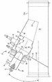
재생 유닛(26)은 주 배기 통로(14)와 소통되는 시스템의 사이드 브랜치 부(34) 내에 위치된다. 재생 유닛(26)은 통로(14)를 통과하는 배기 가스를 디젤 산화 촉매(30)의 효율을 향상시키고 디젤 입자 필터(32)의 재생을 허용할 높은 온도로 가열하도록 사용될 수 있다. The
재생 유닛(26)은 적절한 연료와 산소 공급기(oxygenator)를 주입하기 위한 하나 또는 그 이상의 주입기(36)를 포함할 수 있다. 주입기(36)는 도 1에 도시된 것과 같이, 연료와 산소 공급기 모두를 주입하는 결합된 주입기로서 구성될 수 있거나, 또는 연료와 산소 공급기를 위한 개별 주입기를 포함할 수 있다(도 11). 어떤 적합한 프로세서(들), 센서들, 유동 제어 밸브들, 전기 코일들 등을 사용하여 주입기(36)를 통한 유동들 및 제 1 점화장치(42)에 의한 연료의 점화를 모니터하고 제어하기 위하여 제어 모듈(38)이 제공된다.
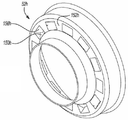
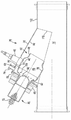
재생 유닛(26)은 조립식 금속 부품들의 다품식(multi-piece) 어셈블리로서 구성되는 하우징(50)을 포함한다. 하우징(50)은 입구 튜브(52), 실린더 형태의 바디(54), 및 출구 튜브(56)를 포함한다. 입구 헤더(inlet header, 58)가 입구 튜브(52)에 고정된다. 입구 헤더(58)는 사이드 브랜치 부(34)에 고정되고 그것의 단부들 중의 하나를 둘러싼다. 다른 단일 또는 다품식 입구 어셈블리가 또한 본 발명의 범위 내에 존재하는 것으로 고려된다. 환상 볼륨(annular volume, 62)이 사이드 브랜치 부(34)의 내부 표면(65) 및 하우징(50)의 외부 표면 사이의 공간 내에 존재한다.The
주입기(36)를 위한 부착 메커니즘을 제공하기 위하여 주입기 마운트(injector mount)가 입구 튜브(52) 및/또는 입구 헤더(58)에 고정된다. 주입기(36)의 노즐 부(66)는 미립화된 연료가 적어도 부분적으로 바디(54)의 내부 실린더형 표면(70)에 의해 정의되는 일차 연소 챔버(68) 내에 주입될 수 있는 것과 같이 입구 튜브(52) 내로 확장한다. 주입기(36)는 연료 입구(72) 및 공기 입구(74)를 포함한다. 연료 입구(72)는 연료 탱크(78), 연료 필터(80), 연료 펌프(82) 및 연료 라인(86)에 의해 서로 연결되는 연료 블록(84)을 포함하는 연료 전달 시스템(76)과 소통된다. 연료 전달 시스템(76)의 부품들의 작동은 선택적으로 탄화수소를 주입기(36)에 제공한다.An injector mount is secured to the
이차 공기 시스템(90)은 이차 공기 필터(92) 및 흡입 공기량 센서(Mass Air Flow(MAF) sensor, 94)를 포함한다. 압축기(96)는 이차 공기 필터(92) 및 흡입 공기량 센서(94)를 통과한 공기를 받는다. 압축기(96)는 과급기(supercharger)의 일부, 터보차저 또는 독립형 전기 압축기를 포함할 수 있다. 공기 입구(74)에 압축기(96)로부터의 출력이 제공된다. 배기 가스 가열이 원해질 때, 연료가 연료 입구(72)를 거쳐 주입되고 미립화된 연료의 스트림을 주입하기 위하여 산소 공급기가 공기 입구(74)를 거쳐 제공된다. 제 1 점화장치(42)는 입구 헤더(58)의 하류의 사이드 브랜치 부(34)에 장착되고 일차 연소 챔버(68) 내의 주입기(36)에 의해 제공되는 연료를 연소하도록 작동된다.
사이드 브랜치 부(34)는 대체로 30도의 각도(A)에서 배기 통로(14)와 교차한다. 재생 유닛(26)에 의해 생산되는 화염(flame)은 대체로 동일한 각도에서 배기 통로 내로 확장한다.The
가늘고 긴 구멍(aperture, 110)은 주 배기 통로(14)를 정의하는 파이프(112)를 통하여 확장한다. 바디(54) 및 출구 튜브(56)의 일부는 배기 통로(14) 내에 위치된다. 엔진(12)으로부터 제공되는 배기 가스는 하우징(50)에 영향을 주고 재생 유닛(26)의 작동 동안에 그것을 냉각시킨다. 게다가, 하우징(50)이 통로(14) 내에 최소로 침해하기 때문에, 배기 가스 배압이 또한 최소로 증가된다. 또한 사이드 브랜치 부(34) 및 주입기(36)가 파이프(112)로부터 최소로 방사상으로 바깥쪽으로 확장한다는 것을 이해하여야 한다. 그러한 배치는 주문자 상표 부착 제조사가 차량 상에 소형 재생 유닛을 더 쉽게 포장하도록 허용한다.An
본 발명의 후처리 시스템에 있어서, 제 1 점화장치(42)는 또한 코일(46)에 결합되는 이온 센서(44)를 포함한다. 이온 센서(44)는 연소 챔버(68) 내에 위치되는 전극의 형태이다. 센서로부터 하우징(50)과 같은 접지에 전기장을 생성하기 위하여 전압이 이온 센서에 적용될 수 있다. 전압이 적용될 때, 전기장은 센서로부터 접지로 방출된다. 만일 전기장에 자유 이온들이 존재하면, 작은 이온 전류가 흐를 수 있다. 이온 전류의 규모는 이온들의 밀도의 표시를 제공한다. 제어 모듈(38)은 화염의 존재 또는 부재를 결정하도록 이온 센서(44)로부터 신호를 검출하고 수신한다. 이온 센서(44)는 또한 점화장치(42)가 오염되었는지를 결정한다.In the aftertreatment system of the present invention, the
오염은 검영, 오일, 또는 다른 오염물질의 증착을 통하여 발생할 수 있다. 점화장치(42)가 오염되었을 때, 적절한 연소는 발생할 수 없다. 제어 모듈(38)은 연료를 연료 입구(72)로, 공기를 공기 입구(74)로 그리고 전기 에너지를 점화장치(42)로 연료의 공급을 제공하고 중단하도록 작동된다. 연료 및 공기의 주입기(36)로의 제공을 개시하기 전에, 제어 모듈(38)은 점화장치(42)가 이온 센서(44)에 의해 제공되는 신호를 통하여 오염되었는지를 결정한다. 만일 점화장치가 작동할 준비가 되었다고 결정하면, 제어 모듈은 엔진 속도, 주변 온도, 차량 속도, 엔진 냉각수 온도, 산소 함량, 흡입 공기량, 디젤 입자 필터(32)를 가로지른 압력 차이, 및 여러 가지 다른 차량 파라미터들과 같은 다수의 엔진 및 차량을 설명할 수 있다. 만일 제어 모듈(38)이 배기 가스 온도 내의공기 증가가 바람직하다고 결정하면, 연료 및 이차 공기가 주입기(36)에 제공된다. 코일(46)은 일차 연소 챔버(68) 내의 연소를 개시하기 위하여 전기 에너지를 점화장치(42)에 공급한다. Contamination may occur through deposition of gum, oil, or other contaminants. When the
제어 모듈(38)은 또한 연료 및 공기의 주입기(36)로의 공급을 중단할 때를 결정하기 위하여 재생 유닛(26)으로부터의 하류의 위치에서 통로(14) 내의 배기 가스의 연소 및 온도를 포함하는 다수의 다른 파라미터를 평가할 수 있다. 예를 들면, 제어 모듈(38)은 특정 위치에서 바람직한 온도를 유지하도록 재생 유닛을 작동함으로써 폐쇄 루프 제어를 실행하기 위하여 재생 유닛(26), 사이드 브랜치 부(34) 내에, 또는 주 통로(14) 내에 위치되는 하나 또는 그 이상의 온도 센서로부터 신호들을 수신할 수 있다. 만일 연소가 예기치 않게 끝나면, 제어 모듈(38)은 연료의 공급을 중단한다. 다른 제어 계획들이 또한 본 발명의 범위 내에 존재한다.The
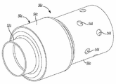
도 3은 사이드 브랜치 부(34)에 결합되는 대안의 재생 유닛(26a)을 도시한다. 재생 유닛(26a)은 하우징(50)의 감소되거나 목이 좁은(necked-down) 출구 튜브 부가 제거된 것을 제외하고는 실질적으로 재생 유닛(26)과 유사하다. 그와 같이, 같은 구성요소들은 "a" 접미사와 동일시될 것이다. 주 바디 부(54a)는 출구 개구부(53a)에서 끝나는 실질적으로 일정한 지름을 포함한다.3 shows an
도 4는 참조 번호 26b로 확인되는 또 다른 대안의 재생 유닛을 도시한다. 재생 유닛(26b)은 하우징(50b)의 더 큰 부(portion)가 배기 통로(14) 내에 위치되도록 야기하기 위하여 길이(L)가 증가된 것을 제외하고는 실질적으로 재생 유닛(26)과 유사하다. 같은 구성요소들은 "b" 접미사를 포함할 것이다. 점화장치(42)의 위치는 노즐(66)의 단부로부터 더 멀어지도록 변경되었다.4 shows another alternative playback unit identified with reference 26b. The regeneration unit 26b is substantially similar to the
도 5 및 6은 소형 재생 유닛(26)의 상류의 파이프(112) 내에 위치되는 전환기 플레이트(diverter plate, 140)를 포함하는 또 다른 대안의 배치를 도시한다. 전환기 플레이트(140)는 그것을 통하여 확장하는 D-형태의 구멍(142)을 포함한다. 전환기 플레이트(140)는 통로를 통하여 흐르는 배기를 하우징(50)을 향하여 그리고 하우징(50) 주위에 흐르도록 강요하기 위하여 도 5에 도시된 것과 같은 각도에 위치된다. 전환된 배기 흐름은 재생 유닛(26)으로부터 파이프(112)를 통하여 흐르는 배기로 열을 전달한다.5 and 6 show yet another alternative arrangement comprising a
도 7은 참조 번호 26c로 확인되는 또 다른 대안의 재생 유닛의 일부를 도시한다. 재생 유닛(26c)은 출구 튜브(56c)의 길이가 증가되고 거기를 통하여 확장하는 복수의 구멍(144)을 포함하는 것을 제외하고는 실질적으로 재생 유닛(26)과 유사하다. 확장된 출구 튜브 길이 및 구멍들(144)은 재생 유닛(26c)의 작동 동안에 연소 화염이 적절하게 유지되고 규제되도록 보장한다. 배기가 통로(14)를 통하여 흐르기 때문에, 배기의 일부는 더 바람직한 온도 분포, 화염 안정성 및 화염 품질을 야기하는 혼합 효과를 생성하는 구멍들(144)을 통과한다.7 shows a part of another alternative playback unit identified with
도 8은 참조 번호 26d로 확인되는 또 다른 대안의 재생 유닛을 도시한다. 재생 유닛(26d)은 재생 유닛(26)의 부품들뿐만 아니라 이차 연소 챔버(146)를 정의하는 부가적인 하우징 부(145)를 포함한다. 제 2 점화장치(148)는 이차 연소 챔버(146) 내로 확장한다. 복수의 구멍(149)은 배기 가스가 이차 연소 챔버(146)로 들어가는 것을 허용하도록 제 2 하우징(145)을 통하여 확장한다. 향상된 배기 가열 및 혼합이 재생 유닛(26d)의 사용을 통하여 달성될 수 있다.8 shows another alternative playback unit identified with reference 26d. Regeneration unit 26d includes an additional housing portion 145 that defines secondary combustion chamber 146 as well as components of
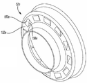
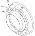
도 9-13은 입구 튜브(52) 대신에 사용될 수 있는 대안의 입구 튜브 구성들을 도시한다. 각각의 변형된 입구 튜브는 단부 벽(152)을 통하여 확장하는 복수의 원주로 떨어져 간격을 두는 구멍(150)을 포함한다. 구멍들(150)은 통로(14)를 통하여 흐르는 배기 가스가 일차 연소 챔버(68)로 들어가는 것을 허용한다. 산소를 구멍들(150)을 거쳐 일차 연소 챔버 내로 제공함으로써, 압축기(96)에 의해 주입기(36)로 제공되는 이차 공기의 압력은 감소될 것이다. 압축기(96)의 비용 및 크기가 또한 감소될 것이다.9-13 illustrate alternative inlet tube configurations that may be used instead of the
도 9에 도시된 입구 튜브(52e)는 일 단부에서 단부 벽(152e)에 부착되는 복수의 플랩(flap, 156e)을 포함한다. 플랩들(155e)은 구멍들(150e)을 통과하는 가스가 소용돌이치는 것을 유도하도록 배치된다. 도 10은 플랩들이 없는 직사각형 형태의 구멍들(150f)을 도시한다. 도 11은 구멍들(150g)의 방사상 내부 범위에 부착되는 복수의 플랩(156g)을 포함한다. 플랩들(156g)은 방사상으로 바깥쪽의 방향으로 배기 흐름에 대하여 비스듬히 확장한다. 도 12는 복수의 구멍(150h) 및 복수의 플랩(156h)을 갖는 또 다른 대안의 입구 튜브 어셈블리(52h)에 관한 것이다. 플랩들(156h)은 방사상으로 안쪽으로 확장한다.The
도 13은 서로 떨어져 원주로 공간을 두는 복수의 원형 구멍(150i)을 도시한다. 어떠한 플랩도 구멍들을 부분적으로 차단하지 않는다. 도 9-13에 도시된 각각의 배치들은 실질적으로 유사한 일차 연소 챔버(68) 내의 흐름 분포를 제공한다.13 shows a plurality of circular holes 150i spaced circumferentially apart from each other. No flap partially blocks the holes. Each of the arrangements shown in FIGS. 9-13 provide a flow distribution in the primary combustion chamber 68 that is substantially similar.
또한 구멍들(150)을 포함하는 설명된 소형 재생 유닛 배치들 중 어느 것은 도 14에 도시된 것과 같이, 상대적으로 낮은 압력에서 압축 공기를 환상 볼륨(62) 내로 주입하기 위하여, 이동된 이차 공기 입구(74j)를 주입기(36j)가 구비될 수 있다는 것이 고려된다. 연료 입구(72j)는 이전에 설명된 것과 같이, 일차 연소 챔버(68j) 내의 미립화된 연료를 주사하도록 위치된다. 환상 볼륨(62j) 내로 주입된 공기의 일부는 구멍들(150i)을 통과하고 이차 공기의 나머지 부는 소형 재생 유닛(26j)을 냉각시키기 위하여 하우징(50j)의 외부 표면 위를 통과한다.Any of the described small regeneration unit arrangements that also include holes 150 may be moved secondary air inlet to inject compressed air into the annular volume 62 at a relatively low pressure, as shown in FIG. 14. It is contemplated that an injector 36j may be provided 74j. The fuel inlet 72j is positioned to inject the atomized fuel in the primary combustion chamber 68j, as previously described. Some of the air injected into the
이전의 실시 예들의 설명은 설명의 목적을 위하여 제공되었다. 이는 이것이 완전하거나 또는 본 발명을 한정하는 것으로 의도되어서는 안 된다. 특정 실시 예의 개별 구성요소들 및 특징들은 일반적으로 그러한 특정 실시 예에 한정하지 않으나, 해당되는 경우에, 구체적으로 도시되거나 설명되지 않더라도, 교체 사용이 가능하고 선택된 실시 예에서 사용될 수 있다. 또한 이는 많은 방식으로 다양할 수 있다. 그러한 변경들은 본 발명이 범위를 벗어나는 것으로 고려되어서는 안 되며, 그러한 모든 변형들은 본 발명의 범위 내에 포함되는 것으로 의도된다.
The description of the previous embodiments has been provided for the purpose of explanation. It is not intended to be exhaustive or to limit the invention. The individual components and features of a particular embodiment are generally not limited to that particular embodiment, but where applicable, although not specifically shown or described, replacement is possible and can be used in the selected embodiment. It can also vary in many ways. Such modifications are not to be considered outside the scope of the present invention, and all such modifications are intended to be included within the scope of the present invention.
10 : 배기 가스 후처리 시스템
12 : 엔진
14 : 주 배기 통로
16 : 흡기 통로
18 : 터보차저
26 : 소형 재생 유닛
28 : 탄화수소 주입기
30 : 디젤 산화 촉매
32 : 디젤 입자 필터
34 : 사이드 브랜치 부
36 : 주입기
38 : 제어 모듈
42 : 제 1 점화장치
44 : 이온 센서
46 : 코일
50 : 하우징
52 : 입구 튜브
54 : 바디
56 : 출구 튜브
58 : 입구 헤더
62 : 환상 볼륨
65 : 사이드 브랜치 부의 내부 표면
66 : 주입기의 노즐 부
68 : 일차 연소 챔버
70 : 바디의 내부 실린더형 표면
72 : 연료 입구
74 : 공기 입구
76 : 연료 전달 시스템
78 : 연료 탱크
80 : 연료 필터
82 : 연료 펌프
84 : 연료 블록
86 : 연료 라인
90 : 이차 공기 시스템
92 : 이차 공기 필터
94 : 흡입 공기량 센서
96 : 압축기
110 : 구멍
112 : 파이프
140 : 전환기 플레이트
142, 144 : 구멍
145 : 제 2 하우징
146 : 이차 연소 챔버
148 : 제 2 점화장치
150 : 구멍
152 : 단부 벽
156e, 156g : 플랩10: Exhaust gas aftertreatment system
12: engine
14: main exhaust passage
16: intake passage
18: turbocharger
26: compact playback unit
28: hydrocarbon injector
30: diesel oxidation catalyst
32: diesel particle filter
34: side branch section
36: Injector
38: control module
42: first ignition device
44: ion sensor
46: coil
50: Housing
52: inlet tube
54: body
56: outlet tube
58: inlet header
62: illusion volume
65: inner surface of the side branch section
66: nozzle part of the injector
68: primary combustion chamber
70: inner cylindrical surface of the body
72: fuel inlet
74: air inlet
76: fuel delivery system
78: fuel tank
80: fuel filter
82: fuel pump
84 fuel block
86: Fuel Line
90: secondary air system
92: secondary air filter
94: intake air volume sensor
96: compressor
110: hole
112: pipe
140: diverter plate
142, 144 holes
145: second housing
146: secondary combustion chamber
148: second ignition device
150: hole
152: end wall
156e, 156g: flap
Claims (20)
상기 엔진으로부터의 상기 배기 스트림을 받도록 적용되는 주 배기 통로;
상기 주 배기 통로와 소통되는 사이드 브랜치;
연료를 연소시키고 상기 주 배기 통로를 통하여 흐르는 배기 가스를 가열하기 위하여 상기 사이드 브랜치 내에 위치하는 재생 유닛;
연료 연소의 존재를 표시하는 신호를 출력하도록 작동되는 이온 센서; 및
배기 온도를 증가시키기 위하여 선택적으로 작동하며, 상기 이온 센서 신호를 기초로 하여 상기 재생 유닛으로 연료의 공급을 제어하도록 작동되는 컨트롤러;를 포함하는 것을 특징으로 하는 시스템.
A system for controlling the temperature of an exhaust stream from an engine at an upstream position from an exhaust aftertreatment device,
A main exhaust passage adapted to receive the exhaust stream from the engine;
A side branch in communication with the main exhaust passage;
A regeneration unit located in the side branch for burning fuel and heating exhaust gas flowing through the main exhaust passage;
An ion sensor operative to output a signal indicative of the presence of fuel combustion; And
And a controller, selectively operable to increase exhaust temperature, the controller operable to control the supply of fuel to the regeneration unit based on the ion sensor signal.
The system of claim 1, further comprising supplying a secondary source of oxygen to the control unit.
3. The system of claim 2, wherein the regeneration unit further comprises a housing defining a primary combustion chamber, wherein the secondary source of fuel and the oxygen is supplied directly to the primary combustion chamber.
4. The system of claim 3, wherein the housing includes a reduced diameter portion at the free distal end.
4. The housing of claim 3, wherein the housing includes a first end supported by the side branch and an unsupported second end, wherein the first end extends therethrough to receive a portion of the exhaust gas stream. System comprising a.
4. The system of claim 3, wherein the housing extends at least partially into the main exhaust passage to cool the housing.
4. The fuel cell of claim 3, wherein the regeneration unit further comprises a housing defining a main combustion chamber, the fuel is supplied directly to the primary combustion chamber, the secondary source of oxygen is supplied to an outer surface of the housing, And the housing allows a portion of the secondary source of oxygen to enter the primary combustion chamber.
The apparatus of claim 1, further comprising a diverter plate located in the main exhaust passage upstream from the regeneration unit, wherein the diverter plate comprises a hole shaped and positioned to direct exhaust gas flow towards the regeneration unit. System characterized in that.
9. The system of claim 8, wherein the aperture is substantially in the form of the letter D.
2. The system of claim 1, wherein the controller stops supplying fuel when the ion sensor signal indicates unexpected disappearance of fuel.
The system of claim 1 wherein the side branch crosses the main exhaust passage at approximately 30 degrees.
2. The system of claim 1, wherein the side branch has a distal end that extends into a main exhaust passage that is free of exhaust gas.
상기 엔진으로부터의 상기 배기 스트림을 받도록 적용되는 주 배기 통로;
상기 주 배기 통로와 소통되는 블라인드 사이드 브랜치;
연료를 연소시키고 상기 주 배기 통로를 통하여 흐르는 배기 가스를 가열하기 위하여 상기 사이드 브랜치 내에 위치되며, 상기 사이드 브랜치의 측벽 내에 위치되고 측벽으로부터 떨어져 위치되는 하우징, 상기 연료를 상기 하우징에 의해 정의되는 챔버로 주입하기 위한 노즐, 및 상기 하우징 내의 상기 연료의 연소를 개시하기 위한 점화장치를 포함하는 재생 유닛; 및
배기 온도를 증가시키기 위하여 상기 재생 유닛을 선택적으로 작동하기 위한 컨트롤러;를 포함하는 것을 특징으로 하는 시스템.
A system for controlling the temperature of an exhaust stream from an engine at an upstream position from an exhaust aftertreatment device,
A main exhaust passage adapted to receive the exhaust stream from the engine;
A blind side branch in communication with the main exhaust passage;
A housing located within the side branch and located within the side branch of the side branch and away from the side wall for combusting fuel and heating the exhaust gas flowing through the main exhaust passage, the fuel to a chamber defined by the housing A regeneration unit including a nozzle for injection, and an ignition device for initiating combustion of the fuel in the housing; And
And a controller for selectively operating the regeneration unit to increase the exhaust temperature.
14. The system of claim 13, further comprising supplying a secondary source of oxygen to the control unit.
15. The system of claim 14, wherein the housing includes a reduced diameter portion at the free distal end.
16. The housing of claim 15, wherein the housing includes a first end supported by the side branch and an unsupported second end, wherein the first end extends therethrough to receive a portion of the exhaust gas stream. System comprising a.
14. The system of claim 13, wherein the housing extends at least partially into the main exhaust passage to cool the housing.
14. The system of claim 13, further comprising a secondary air source supplied to the region between the housing and the side wall.
15. The apparatus of claim 13, further comprising a diverter plate located in the main exhaust passage upstream from the regeneration unit, wherein the diverter plate comprises a hole shaped and positioned to direct exhaust gas flow towards the regeneration unit. System characterized in that.
Applications Claiming Priority (5)
| Application Number | Priority Date | Filing Date | Title |
|---|---|---|---|
| US201161433297P | 2011-01-17 | 2011-01-17 | |
| US61/433,297 | 2011-01-17 | ||
| US13/197,829 US20110289906A1 (en) | 2009-04-27 | 2011-08-04 | Miniature Regeneration Unit |
| US13/197,829 | 2011-08-04 | ||
| PCT/US2011/065770 WO2012099667A2 (en) | 2011-01-17 | 2011-12-19 | Miniature regeneration unit |
Publications (1)
| Publication Number | Publication Date |
|---|---|
| KR20140034143A true KR20140034143A (en) | 2014-03-19 |
Family
ID=46516292
Family Applications (1)
| Application Number | Title | Priority Date | Filing Date |
|---|---|---|---|
| KR1020137021453A KR20140034143A (en) | 2011-01-17 | 2011-12-19 | Miniature regeneration unit |
Country Status (7)
| Country | Link |
|---|---|
| US (1) | US20110289906A1 (en) |
| JP (1) | JP2014505827A (en) |
| KR (1) | KR20140034143A (en) |
| CN (1) | CN103314193A (en) |
| BR (1) | BR112013017820A2 (en) |
| DE (1) | DE112011104731T5 (en) |
| WO (1) | WO2012099667A2 (en) |
Families Citing this family (27)
| Publication number | Priority date | Publication date | Assignee | Title |
|---|---|---|---|---|
| KR102048722B1 (en) | 2012-02-27 | 2019-11-26 | 디이이씨 아이엔씨 | Oxygen-rich plasma generators for boosting internal combustion engines |
| US9133743B2 (en) | 2012-03-15 | 2015-09-15 | Tenneco Automotive Operating Company Inc. | Exhaust treatment secondary air supply system |
| US8959902B2 (en) | 2013-02-27 | 2015-02-24 | Tenneco Automotive Operating Company Inc. | Exhaust treatment burner and mixer system |
| US9027331B2 (en) * | 2013-02-27 | 2015-05-12 | Tenneco Automotive Operating Company Inc. | Exhaust aftertreatment burner with preheated combustion air |
| US9027332B2 (en) * | 2013-02-27 | 2015-05-12 | Tenneco Automotive Operating Company Inc. | Ion sensor with decoking heater |
| US8991163B2 (en) | 2013-02-27 | 2015-03-31 | Tenneco Automotive Operating Company Inc. | Burner with air-assisted fuel nozzle and vaporizing ignition system |
| US9234444B2 (en) * | 2013-02-28 | 2016-01-12 | Caterpillar Inc. | Flame detection system for particulate filter regeneration |
| US8893478B2 (en) | 2013-03-01 | 2014-11-25 | Tenneco Automotive Operating Company Inc. | Compressor for exhaust treatment system |
| US9057303B2 (en) | 2013-03-14 | 2015-06-16 | Tenneco Automotive Operating Company Inc. | Exhaust system for dual fuel engines |
| US9534525B2 (en) | 2015-05-27 | 2017-01-03 | Tenneco Automotive Operating Company Inc. | Mixer assembly for exhaust aftertreatment system |
| US10519829B2 (en) | 2016-02-22 | 2019-12-31 | Hino Motors, Ltd. | Exhaust purification system |
| KR20220123330A (en) | 2016-03-07 | 2022-09-06 | 하이테크 파워, 인크. | A method of generating and distributing a second fuel for an internal combustion engine |
| DE102016112827A1 (en) * | 2016-07-13 | 2018-01-18 | Dr. Ing. H.C. F. Porsche Aktiengesellschaft | Internal combustion engine with an exhaust gas turbocharger and a particulate filter and method for operating a particulate filter |
| CN107013286A (en) * | 2017-05-26 | 2017-08-04 | 凯龙高科技股份有限公司 | A kind of diesel engine DPF blast pipes fuel oil and air pre-mixing close injection apparatus |
| US20190234348A1 (en) * | 2018-01-29 | 2019-08-01 | Hytech Power, Llc | Ultra Low HHO Injection |
| WO2019148241A1 (en) * | 2018-02-01 | 2019-08-08 | Hydroflex Technologies Pty Ltd | An exhaust after-treatment system and method |
| US11118785B2 (en) * | 2018-10-26 | 2021-09-14 | Delavan Inc. | Fuel injectors for exhaust heaters |
| DE102019211114A1 (en) * | 2019-07-26 | 2021-01-28 | Volkswagen Aktiengesellschaft | Exhaust aftertreatment system and method for exhaust aftertreatment of an internal combustion engine |
| DE102019134345B3 (en) * | 2019-12-13 | 2021-05-12 | Dr. Ing. H.C. F. Porsche Aktiengesellschaft | Method for an exhaust system of a motor vehicle |
| CN112594037A (en) * | 2020-11-20 | 2021-04-02 | 沪东重机有限公司 | Afterburning system and method for increasing temperature of selective catalytic reduction flue gas |
| EP4019748B1 (en) | 2020-12-23 | 2023-12-06 | Marelli Europe S.p.A. | Heating device for an exhaust system of an internal combustion engine |
| IT202100001880A1 (en) | 2021-01-29 | 2022-07-29 | Marelli Europe Spa | HEATER DEVICE FOR AN EXHAUST SYSTEM OF AN INTERNAL COMBUSTION ENGINE |
| IT202100001892A1 (en) * | 2021-01-29 | 2022-07-29 | Marelli Europe Spa | HEATER DEVICE FOR AN EXHAUST SYSTEM OF AN INTERNAL COMBUSTION ENGINE |
| IT202100001871A1 (en) * | 2021-01-29 | 2022-07-29 | Marelli Europe Spa | HEATER DEVICE FOR AN EXHAUST SYSTEM OF AN INTERNAL COMBUSTION ENGINE |
| EP4056818B1 (en) | 2021-02-26 | 2023-11-22 | Marelli Europe S.p.A. | Heating device for an exhaust system of an internal combustion engine |
| IT202100017258A1 (en) * | 2021-06-30 | 2022-12-30 | Marelli Europe Spa | METHOD OF CHECKING A BURNER FOR AN EXHAUST SYSTEM OF AN INTERNAL COMBUSTION ENGINE |
| IT202200006179A1 (en) * | 2022-03-29 | 2023-09-29 | Marelli Europe Spa | HEATER DEVICE FOR AN EXHAUST SYSTEM OF AN INTERNAL COMBUSTION ENGINE |
Family Cites Families (13)
| Publication number | Priority date | Publication date | Assignee | Title |
|---|---|---|---|---|
| JPS5939915A (en) * | 1982-08-27 | 1984-03-05 | Mazda Motor Corp | Exhaust gas purifying device for diesel engine |
| DE3729861C2 (en) * | 1987-09-05 | 1995-06-22 | Deutsche Forsch Luft Raumfahrt | Method for operating a soot filter device for a diesel engine and soot filter device for carrying out this method |
| US5339630A (en) * | 1992-08-28 | 1994-08-23 | General Motors Corporation | Exhaust burner catalyst preheater |
| DE4239079A1 (en) * | 1992-11-20 | 1994-05-26 | Pierburg Gmbh | Burner system for exhaust gas detoxification or purification of an internal combustion engine |
| US5571484A (en) * | 1995-04-25 | 1996-11-05 | General Motors Corporation | Catalytic converter heater |
| AU2003276614A1 (en) * | 2002-06-17 | 2003-12-31 | Southwest Research Institute | Method for controlling exhausted gas emissions |
| JP2004324587A (en) * | 2003-04-25 | 2004-11-18 | Mitsubishi Fuso Truck & Bus Corp | Emission control device of internal combustion engine |
| US7685811B2 (en) * | 2004-01-13 | 2010-03-30 | Emcon Technologies Llc | Method and apparatus for controlling a fuel-fired burner of an emission abatement assembly |
| US7677031B2 (en) * | 2005-07-26 | 2010-03-16 | Caterpillar Inc. | Particulate loading monitoring system |
| US7628007B2 (en) * | 2005-12-21 | 2009-12-08 | Honeywell International Inc. | Onboard diagnostics for anomalous cylinder behavior |
| DE102006060471A1 (en) * | 2006-12-19 | 2008-06-26 | J. Eberspächer GmbH & Co. KG | Motor exhaust assembly has a heater, upstream of the catalyst or particle filter, to raise the exhaust gas temperature when the motor is started from cold |
| US8006482B2 (en) * | 2007-03-02 | 2011-08-30 | Caterpillar Inc. | Method of purging fluid injector by heating |
| US8511075B2 (en) * | 2008-09-19 | 2013-08-20 | Caterpillar Inc. | Flame deflector for emissions control system |
-
2011
- 2011-08-04 US US13/197,829 patent/US20110289906A1/en not_active Abandoned
- 2011-12-19 JP JP2013549425A patent/JP2014505827A/en active Pending
- 2011-12-19 CN CN2011800653407A patent/CN103314193A/en active Pending
- 2011-12-19 BR BR112013017820A patent/BR112013017820A2/en not_active IP Right Cessation
- 2011-12-19 KR KR1020137021453A patent/KR20140034143A/en not_active Application Discontinuation
- 2011-12-19 DE DE112011104731T patent/DE112011104731T5/en not_active Withdrawn
- 2011-12-19 WO PCT/US2011/065770 patent/WO2012099667A2/en active Application Filing
Also Published As
| Publication number | Publication date |
|---|---|
| CN103314193A (en) | 2013-09-18 |
| WO2012099667A3 (en) | 2012-11-01 |
| DE112011104731T5 (en) | 2013-11-28 |
| WO2012099667A2 (en) | 2012-07-26 |
| BR112013017820A2 (en) | 2016-10-11 |
| US20110289906A1 (en) | 2011-12-01 |
| JP2014505827A (en) | 2014-03-06 |
Similar Documents
| Publication | Publication Date | Title |
|---|---|---|
| KR20140034143A (en) | Miniature regeneration unit | |
| KR20140050092A (en) | Exhaust treatment system with hydrocarbon lean nox catalyst | |
| JP4787330B2 (en) | Exhaust and intake gas temperature control | |
| US20080083215A1 (en) | Standalone thermal energy recycling device for engine after-treatment systems | |
| JP5468263B2 (en) | Air treatment system with aftertreatment | |
| KR20120132473A (en) | Snapper valve for hot end systems with burners | |
| JP2014507591A (en) | Coaxial inlet / outlet exhaust treatment device | |
| JP2012525540A (en) | Diesel aftertreatment system | |
| JP2011094625A (en) | Internal combustion engine exhaust system | |
| US20110225969A1 (en) | Compressor bypass to exhaust for particulate trap regeneration | |
| US20130061579A1 (en) | Exhaust Gas Aftertreatment System For Engines Equipped With Exhaust Gas Recirculation | |
| US7805931B2 (en) | Self-sustaining oxy-exothermal filter regeneration system | |
| US8516802B2 (en) | High volume exhaust gas treatment system | |
| JP5033869B2 (en) | Emission reduction system operating method and apparatus | |
| JP5352676B2 (en) | Internal combustion engine system and particulate filter device for internal combustion engine system | |
| JP2010078315A (en) | Flame glow plug | |
| JP2009092015A (en) | Exhaust emission control device | |
| JP2007255256A (en) | Exhaust emission control device in internal combustion engine | |
| WO2018094420A1 (en) | Internal combustion engine aftertreatment heating loop | |
| US20180058283A1 (en) | Oxidation of engine generated particulate matter utilizing exhaust manifold gases | |
| JP5266105B2 (en) | Desulfurization equipment | |
| WO2011129051A1 (en) | Combustion/temperature increase control method and device for after-treatment burner system | |
| KR20240088710A (en) | Exhaust system and its components | |
| JP2004003400A (en) | Filter regeneration fitment in internal combustion engine |
Legal Events
| Date | Code | Title | Description |
|---|---|---|---|
| WITN | Application deemed withdrawn, e.g. because no request for examination was filed or no examination fee was paid |