KR20140033345A - Shower head - Google Patents
Shower head Download PDFInfo
- Publication number
- KR20140033345A KR20140033345A KR1020137024378A KR20137024378A KR20140033345A KR 20140033345 A KR20140033345 A KR 20140033345A KR 1020137024378 A KR1020137024378 A KR 1020137024378A KR 20137024378 A KR20137024378 A KR 20137024378A KR 20140033345 A KR20140033345 A KR 20140033345A
- Authority
- KR
- South Korea
- Prior art keywords
- venturi
- shower head
- air
- handle
- water
- Prior art date
Links
- XLYOFNOQVPJJNP-UHFFFAOYSA-N water Substances O XLYOFNOQVPJJNP-UHFFFAOYSA-N 0.000 claims abstract description 69
- 238000009792 diffusion process Methods 0.000 claims abstract description 17
- 238000000034 method Methods 0.000 claims description 17
- 241000220317 Rosa Species 0.000 claims description 7
- 238000011144 upstream manufacturing Methods 0.000 claims description 2
- 238000005406 washing Methods 0.000 description 3
- 230000009471 action Effects 0.000 description 2
- 238000010586 diagram Methods 0.000 description 2
- 238000004519 manufacturing process Methods 0.000 description 2
- 230000004048 modification Effects 0.000 description 2
- 238000012986 modification Methods 0.000 description 2
- 210000002445 nipple Anatomy 0.000 description 2
- 230000033228 biological regulation Effects 0.000 description 1
- 230000008878 coupling Effects 0.000 description 1
- 238000010168 coupling process Methods 0.000 description 1
- 238000005859 coupling reaction Methods 0.000 description 1
- 230000007423 decrease Effects 0.000 description 1
- 238000001035 drying Methods 0.000 description 1
- 230000000694 effects Effects 0.000 description 1
- 238000005265 energy consumption Methods 0.000 description 1
- 238000005086 pumping Methods 0.000 description 1
- 239000010865 sewage Substances 0.000 description 1
- 230000007704 transition Effects 0.000 description 1
Images


Classifications
-
- B—PERFORMING OPERATIONS; TRANSPORTING
- B05—SPRAYING OR ATOMISING IN GENERAL; APPLYING FLUENT MATERIALS TO SURFACES, IN GENERAL
- B05B—SPRAYING APPARATUS; ATOMISING APPARATUS; NOZZLES
- B05B7/00—Spraying apparatus for discharge of liquids or other fluent materials from two or more sources, e.g. of liquid and air, of powder and gas
- B05B7/02—Spray pistols; Apparatus for discharge
- B05B7/04—Spray pistols; Apparatus for discharge with arrangements for mixing liquids or other fluent materials before discharge
- B05B7/0416—Spray pistols; Apparatus for discharge with arrangements for mixing liquids or other fluent materials before discharge with arrangements for mixing one gas and one liquid
-
- B—PERFORMING OPERATIONS; TRANSPORTING
- B05—SPRAYING OR ATOMISING IN GENERAL; APPLYING FLUENT MATERIALS TO SURFACES, IN GENERAL
- B05B—SPRAYING APPARATUS; ATOMISING APPARATUS; NOZZLES
- B05B1/00—Nozzles, spray heads or other outlets, with or without auxiliary devices such as valves, heating means
- B05B1/26—Nozzles, spray heads or other outlets, with or without auxiliary devices such as valves, heating means with means for mechanically breaking-up or deflecting the jet after discharge, e.g. with fixed deflectors; Breaking-up the discharged liquid or other fluent material by impinging jets
-
- A—HUMAN NECESSITIES
- A47—FURNITURE; DOMESTIC ARTICLES OR APPLIANCES; COFFEE MILLS; SPICE MILLS; SUCTION CLEANERS IN GENERAL
- A47K—SANITARY EQUIPMENT NOT OTHERWISE PROVIDED FOR; TOILET ACCESSORIES
- A47K3/00—Baths; Douches; Appurtenances therefor
- A47K3/28—Showers or bathing douches
-
- A—HUMAN NECESSITIES
- A61—MEDICAL OR VETERINARY SCIENCE; HYGIENE
- A61H—PHYSICAL THERAPY APPARATUS, e.g. DEVICES FOR LOCATING OR STIMULATING REFLEX POINTS IN THE BODY; ARTIFICIAL RESPIRATION; MASSAGE; BATHING DEVICES FOR SPECIAL THERAPEUTIC OR HYGIENIC PURPOSES OR SPECIFIC PARTS OF THE BODY
- A61H33/00—Bathing devices for special therapeutic or hygienic purposes
- A61H33/02—Bathing devices for use with gas-containing liquid, or liquid in which gas is led or generated, e.g. carbon dioxide baths
-
- A—HUMAN NECESSITIES
- A61—MEDICAL OR VETERINARY SCIENCE; HYGIENE
- A61H—PHYSICAL THERAPY APPARATUS, e.g. DEVICES FOR LOCATING OR STIMULATING REFLEX POINTS IN THE BODY; ARTIFICIAL RESPIRATION; MASSAGE; BATHING DEVICES FOR SPECIAL THERAPEUTIC OR HYGIENIC PURPOSES OR SPECIFIC PARTS OF THE BODY
- A61H33/00—Bathing devices for special therapeutic or hygienic purposes
- A61H33/60—Components specifically designed for the therapeutic baths of groups A61H33/00
- A61H33/601—Inlet to the bath
- A61H33/6021—Nozzles
- A61H33/6036—Hand-held connected to a supply hose
-
- A—HUMAN NECESSITIES
- A61—MEDICAL OR VETERINARY SCIENCE; HYGIENE
- A61H—PHYSICAL THERAPY APPARATUS, e.g. DEVICES FOR LOCATING OR STIMULATING REFLEX POINTS IN THE BODY; ARTIFICIAL RESPIRATION; MASSAGE; BATHING DEVICES FOR SPECIAL THERAPEUTIC OR HYGIENIC PURPOSES OR SPECIFIC PARTS OF THE BODY
- A61H33/00—Bathing devices for special therapeutic or hygienic purposes
- A61H33/60—Components specifically designed for the therapeutic baths of groups A61H33/00
- A61H33/601—Inlet to the bath
- A61H33/6021—Nozzles
- A61H33/6052—Having flow regulating means
-
- B—PERFORMING OPERATIONS; TRANSPORTING
- B05—SPRAYING OR ATOMISING IN GENERAL; APPLYING FLUENT MATERIALS TO SURFACES, IN GENERAL
- B05B—SPRAYING APPARATUS; ATOMISING APPARATUS; NOZZLES
- B05B1/00—Nozzles, spray heads or other outlets, with or without auxiliary devices such as valves, heating means
- B05B1/002—Nozzles, spray heads or other outlets, with or without auxiliary devices such as valves, heating means designed to reduce the generation or the transmission of noise or to produce a particular sound; associated with noise monitoring means
-
- B—PERFORMING OPERATIONS; TRANSPORTING
- B05—SPRAYING OR ATOMISING IN GENERAL; APPLYING FLUENT MATERIALS TO SURFACES, IN GENERAL
- B05B—SPRAYING APPARATUS; ATOMISING APPARATUS; NOZZLES
- B05B15/00—Details of spraying plant or spraying apparatus not otherwise provided for; Accessories
- B05B15/60—Arrangements for mounting, supporting or holding spraying apparatus
- B05B15/65—Mounting arrangements for fluid connection of the spraying apparatus or its outlets to flow conduits
-
- B—PERFORMING OPERATIONS; TRANSPORTING
- B05—SPRAYING OR ATOMISING IN GENERAL; APPLYING FLUENT MATERIALS TO SURFACES, IN GENERAL
- B05B—SPRAYING APPARATUS; ATOMISING APPARATUS; NOZZLES
- B05B7/00—Spraying apparatus for discharge of liquids or other fluent materials from two or more sources, e.g. of liquid and air, of powder and gas
- B05B7/02—Spray pistols; Apparatus for discharge
- B05B7/04—Spray pistols; Apparatus for discharge with arrangements for mixing liquids or other fluent materials before discharge
- B05B7/0416—Spray pistols; Apparatus for discharge with arrangements for mixing liquids or other fluent materials before discharge with arrangements for mixing one gas and one liquid
- B05B7/0441—Spray pistols; Apparatus for discharge with arrangements for mixing liquids or other fluent materials before discharge with arrangements for mixing one gas and one liquid with one inner conduit of liquid surrounded by an external conduit of gas upstream the mixing chamber
- B05B7/045—Spray pistols; Apparatus for discharge with arrangements for mixing liquids or other fluent materials before discharge with arrangements for mixing one gas and one liquid with one inner conduit of liquid surrounded by an external conduit of gas upstream the mixing chamber the gas and liquid flows being parallel just upstream the mixing chamber
-
- B—PERFORMING OPERATIONS; TRANSPORTING
- B05—SPRAYING OR ATOMISING IN GENERAL; APPLYING FLUENT MATERIALS TO SURFACES, IN GENERAL
- B05B—SPRAYING APPARATUS; ATOMISING APPARATUS; NOZZLES
- B05B7/00—Spraying apparatus for discharge of liquids or other fluent materials from two or more sources, e.g. of liquid and air, of powder and gas
- B05B7/02—Spray pistols; Apparatus for discharge
- B05B7/06—Spray pistols; Apparatus for discharge with at least one outlet orifice surrounding another approximately in the same plane
- B05B7/062—Spray pistols; Apparatus for discharge with at least one outlet orifice surrounding another approximately in the same plane with only one liquid outlet and at least one gas outlet
-
- A—HUMAN NECESSITIES
- A61—MEDICAL OR VETERINARY SCIENCE; HYGIENE
- A61H—PHYSICAL THERAPY APPARATUS, e.g. DEVICES FOR LOCATING OR STIMULATING REFLEX POINTS IN THE BODY; ARTIFICIAL RESPIRATION; MASSAGE; BATHING DEVICES FOR SPECIAL THERAPEUTIC OR HYGIENIC PURPOSES OR SPECIFIC PARTS OF THE BODY
- A61H33/00—Bathing devices for special therapeutic or hygienic purposes
- A61H33/02—Bathing devices for use with gas-containing liquid, or liquid in which gas is led or generated, e.g. carbon dioxide baths
- A61H33/027—Gas-water mixing nozzles therefor
-
- B—PERFORMING OPERATIONS; TRANSPORTING
- B05—SPRAYING OR ATOMISING IN GENERAL; APPLYING FLUENT MATERIALS TO SURFACES, IN GENERAL
- B05B—SPRAYING APPARATUS; ATOMISING APPARATUS; NOZZLES
- B05B1/00—Nozzles, spray heads or other outlets, with or without auxiliary devices such as valves, heating means
- B05B1/14—Nozzles, spray heads or other outlets, with or without auxiliary devices such as valves, heating means with multiple outlet openings; with strainers in or outside the outlet opening
- B05B1/18—Roses; Shower heads
-
- B—PERFORMING OPERATIONS; TRANSPORTING
- B05—SPRAYING OR ATOMISING IN GENERAL; APPLYING FLUENT MATERIALS TO SURFACES, IN GENERAL
- B05B—SPRAYING APPARATUS; ATOMISING APPARATUS; NOZZLES
- B05B7/00—Spraying apparatus for discharge of liquids or other fluent materials from two or more sources, e.g. of liquid and air, of powder and gas
- B05B7/16—Spraying apparatus for discharge of liquids or other fluent materials from two or more sources, e.g. of liquid and air, of powder and gas incorporating means for heating or cooling the material to be sprayed
- B05B7/1606—Spraying apparatus for discharge of liquids or other fluent materials from two or more sources, e.g. of liquid and air, of powder and gas incorporating means for heating or cooling the material to be sprayed the spraying of the material involving the use of an atomising fluid, e.g. air
- B05B7/1613—Spraying apparatus for discharge of liquids or other fluent materials from two or more sources, e.g. of liquid and air, of powder and gas incorporating means for heating or cooling the material to be sprayed the spraying of the material involving the use of an atomising fluid, e.g. air comprising means for heating the atomising fluid before mixing with the material to be sprayed
- B05B7/162—Spraying apparatus for discharge of liquids or other fluent materials from two or more sources, e.g. of liquid and air, of powder and gas incorporating means for heating or cooling the material to be sprayed the spraying of the material involving the use of an atomising fluid, e.g. air comprising means for heating the atomising fluid before mixing with the material to be sprayed and heat being transferred from the atomising fluid to the material to be sprayed
- B05B7/1626—Spraying apparatus for discharge of liquids or other fluent materials from two or more sources, e.g. of liquid and air, of powder and gas incorporating means for heating or cooling the material to be sprayed the spraying of the material involving the use of an atomising fluid, e.g. air comprising means for heating the atomising fluid before mixing with the material to be sprayed and heat being transferred from the atomising fluid to the material to be sprayed at the moment of mixing
Abstract
샤워 헤드(40)는 수렴부(46), 쓰로트(50) 및 확산부(52)를 구비한 벤츄리(48)를 통해, 압축 공기 공급기로부터 샤워 방출 개구(56)로 흐르는 압축 공기의 흐름을 위한 공기 통로와, 물 공급기로부터 벤츄리에 있는 물 방출 개구(60)로 흐르는 물의 흐름을 위한 물 통로(58;92)를 포함하고, 벤츄리는 사용중에, 공기 흐름의 전체 방향이 벤츄리에서 실질적 각도로 방향전환하도록 구성된다. 벤츄리의 이러한 접힘으로 샤워 헤드의 콤팩트한 구성을 제공할 수 있다.The shower head 40 receives a flow of compressed air flowing from the compressed air supply to the shower discharge opening 56 through a venturi 48 having a converging portion 46, a throat 50, and a diffusion portion 52. And an air passage (58; 92) for the flow of water from the water supply to the water discharge opening (60) in the venturi, the venturi being in use, wherein the overall direction of the air flow is at a substantial angle in the venturi. Configured to redirect. This folding of the venturi can provide a compact configuration of the shower head.
Description
본 발명은 샤워 헤드(shower head)에 관한 것이다.The present invention relates to a shower head.
샤워는 목욕보다 상대적으로 물의 소비가 적으며, 이에 따라서 물을 가열하기 위한 에너지도 보다 적게 소비되는 것으로 알려져 있다. 그럼에도 불구하고, 샤워할 때 사용되는 물과 에너지 양에 대한 염려가 존재하는 것도 사실이다. 예를 들면, 물과 에너지 사용을 줄이기 위한 시도로서, 1992년 미국에서는 연방법규가 도입되었는데, 이 법규에 따르면 분당 2.5US 갤론(gallon)(분당 약 9.5 리터)으로 샤워 헤드 유속(flow rate)을 제한하고 있으며, 그리고 일부 도시에서는 이미 이 보다 더 엄격한 법규를 시행하고 있다. 그러나, 많은 사람들은 이러한 낮은 유속으로는 충분히 강한 느낌을 주는 샤워를 제공할 수 없다는 것을 알고 있다. 2009. 11. 13. 자 온라인 월 스트리트 저널의 논설에서 보고된 바와 같이, 소비자들은 종종 샤워 헤드에서 흐름 규제기(flow restrictor)를 제거하여 유속을 증가시키고 있다(그리고, 실질적으로, 몇몇의 샤워 헤드가 제공되는 포장물에는 그 흐름 규제기를 제거하는 방법의 상세한 설명을 포함하고 있다). 이와는 달리, 또는 부가적으로, 사람들은 샤워 공간(또는 샤워 박스)에 하나 이상의 샤워 헤드를 설치하고 있다.Showers are known to consume less water than baths, and thus consume less energy to heat the water. Nevertheless, there is a concern about the amount of water and energy used when showering. For example, in an attempt to reduce water and energy use, federal law was introduced in the United States in 1992, which regulates shower head flow rate at 2.5 US gallons per minute (approximately 9.5 liters per minute). There are restrictions, and some cities already have stricter regulations. However, many people know that such low flow rates cannot provide a shower that is strong enough. As reported in the editorial of the online Wall Street Journal on November 13, 2009, consumers often increase the flow rate by removing flow restrictors from the shower head (and, in effect, several shower heads). The package provided with the contains a detailed description of how to remove the flow regulator). Alternatively or additionally, people are installing one or more shower heads in a shower space (or shower box).
예를 들면, 샤워 헤드에 터빈을 설치하거나, 물 흐름 속으로 공기를 인도하는 벤츄리(venturi)를 통해 물을 강제로 통과시키는 방식으로 물과 공기를 혼합하여 샤워의 겉보기 힘(apparent power)을 향상시키는 기술이 공지되어 있다.For example, the shower's apparent power is enhanced by installing a turbine in the shower head or mixing water and air by forcing water through a venturi that directs air into the water stream. Techniques for making are known.
또한, 샤워 헤드에 상대적으로 높은 유속으로 공기를 펌프질하여 공기를 벤츄리에 강제로 통과시키고, 벤츄리에서 물을 공기 흐름에 도입하여 샤워의 겉보기 힘을 더욱 향상시킬 수 있다는 사실이 특허문헌 WO2009/056887A1을 통해 공지되어 있다.In addition, the fact that pumping air at a relatively high flow rate to the shower head forcibly passes the air through the venturi, the water can be introduced into the air flow in the venturi to further improve the apparent force of the shower patent document WO2009 / 056887A1 It is known through.
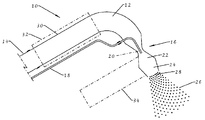
WO2009/056887A1에 개시된 타입의 샤워 헤드가 첨부도면의 도 1에 개략적으로 도시되어 있다. 샤워 헤드(10)는 압축 공기 호스(14)로부터 벤츄리(16)까지 걸쳐 있는 상대적으로 큰 구멍의 통로(12)를 구비한다. 상대적으로 작은 구멍의 물 호스(18)로부터 온수가 벤츄리(16)의 쓰로트(20) 영역에서 공기 흐름 내로 도입된다. 벤츄리(16)의 확산부(22)에서 물은 분열되어 물방울로 되고, 이어서 물방울들은 수렴 노즐(24)을 통과하면서 가속화되며, 이 수렴 노즐(34)은 샤워 헤드(10)에 의해 생성된 소음을 경감시키고, 이어서 물방울들이 배출 개구(28)로부터 강한 샤워(분출수)(26)로서 방출된다. 샤워 헤드(10)에는 배출 개구(28)에 걸쳐있는 로즈(rose: 일명 "샤워 로즈")가 없다. 샤워 헤드(10)에 공급되는 공기는 가열되며, 이 경우, 샤워 헤드(10)는 샤워 이후 공기만으로 사용자의 건조를 위해 사용될 수도 있다. 샤워 중에 공기가 가열되지 않을 경우는, 사용자가 동일한 유효 온도를 느끼기 위해서 종래의 샤워(분출수) 보다 다소 높은 수온이 필요할 수도 있다.A shower head of the type disclosed in WO2009 / 056887A1 is shown schematically in FIG. 1 of the accompanying drawings. The
WO2009/056887A1에서 개시된 구성은 WO2009/056887A1에서 상세히 설명한 바와 같이, 종래의 샤워 보다는 많은 장점을 가지고 있지만, 가장 중요한 점은 동일한 겉보기 힘의 종래 샤워와 비교할 때 물의 소비와 에너지 소비를 극적으로 감소시킨다는 점이다.The configuration disclosed in WO2009 / 056887A1 has many advantages over conventional showers, as detailed in WO2009 / 056887A1, but most importantly, it dramatically reduces water consumption and energy consumption compared to conventional showers of the same apparent force. to be.
도 1에 도시한 구성은 샤워 헤드가 샤워 공간에서 또는 욕조 위에서 벽에 고정되면 완벽하게 만족할 수도 있다. 그러나, 많은 사람들은 또한 샤워 헤드를 손으로 잡을 수 있기를 바라며, 이러한 경우의 예로는, 샤워 중에 신체의 특정 부분을 세척할 때, 목욕을 하는 중에 머리를 감을 때(샤워 헤드가 욕조 위에 있다면), 애완 동물(pet)을 세척할 때 등을 들 수 있다. 따라서, 샤워 헤드는 편의를 위해 핸들의 형태가 필요하다. 대부분의 종래 샤워 헤드에 있어서는 핸들은 편의상 샤워 헤드의 방출방향에 대해 대략 직각으로 연장되고, 물은 핸들의 선단부에 연결된 호스로부터, 핸들을 경유하여 방출 개구(들)로 흐른다. 그러나, 도 1에 도시한 구성은 상대적으로 큰 구멍의 공기 통로(12)와 도 1의 샤워 헤드(10)에서의 벤츄리(16)를 포함하기 때문에, 공기 통로(12)의 일 부분(30) 둘레에 핸들을 배치하는 구성[쇄선(32)으로 표시함)] 또는 별도의 부재로서 예를 들면 벤츄리(16)의 확산부(22)와 수렴 노즐(24)에 대해 직각으로 연장되는 구성[일점 쇄선(34)으로 도시함]은 샤워 헤드의 구성을 복잡하게 한다.The configuration shown in FIG. 1 may be perfectly satisfactory if the shower head is fixed to the wall in the shower space or over the bathtub. However, many people also want to be able to hold the shower head by hand, for example, when washing certain parts of the body during a shower, when washing the head while taking a bath (if the shower head is over a bathtub). , When washing pets. Thus, the shower head needs the shape of a handle for convenience. In most conventional shower heads the handle extends approximately at right angles to the discharge direction of the shower head for convenience, and water flows from the hose connected to the tip of the handle to the discharge opening (s) via the handle. However, since the configuration shown in FIG. 1 includes a relatively large bore air passage 12 and a
본 발명의 목적은 또는 적어도 특정 실시예의 목적은 상기 종래 기술의 문제를 해소하는 것이다.It is an object of the present invention, or at least the purpose of certain embodiments, to solve the problems of the prior art.
본 발명의 일 양태에 따라서 제공되는 샤워 헤드는 WO2009/056887A1의 샤워 헤드와 공통으로, 수렴부, 쓰로트 및 확산부를 구비한 벤츄리를 통해, 압축 공기 공급기로부터 샤워 방출 개구로 흐르는 압축 공기의 흐름을 위한 공기 통로와, 물 공급기로부터 상기 벤츄리에 위치한 물 방출 개구로 흐르는 물의 흐름을 위한 물 통로를 포함한다. WO2009/056887A1의 샤워 헤드와는 대조적으로, 본 발명의 제1양태에 따른 샤워 헤드에 있어서, 상기 벤츄리는 사용중에, 공기 흐름의 전체 방향이 벤츄리에서 실질적 각도로 방향전환되도록 구성된다. 이러한 벤츄리의 접힘(굽힘) 구조는 바람직하게는 쓰로트에 또는 쓰로트에 인근한 곳에, 바람직하게는 45° 내지 135°사이의 각도로 굽혀져 샤워 헤드의 콤팩트한 구성을 제공할 수 있도록 하며, 이 부분에 대해서는 하기 상세한 설명을 통해 명백히 이해될 수 있다.The shower head provided according to one aspect of the present invention, in common with the shower head of WO2009 / 056887A1, receives a flow of compressed air flowing from the compressed air supply to the shower outlet opening through a venturi having a converging portion, a throat and a diffusion portion. And an air passage for the flow of water from the water supply to the water discharge opening located in the venturi. In contrast to the shower head of WO2009 / 056887A1, in the shower head according to the first aspect of the invention, the venturi is configured such that during use the entire direction of the air flow is diverted at a substantial angle in the venturi. This venturi fold (bend) structure is preferably bent at or near the throat, preferably at an angle between 45 ° and 135 ° to provide a compact configuration of the shower head, This part can be clearly understood through the following detailed description.
상기 벤츄리는 사용중에, 상기 벤츄리의 확산부에서 공기 흐름의 전체 방향이 축 방향을 따르도록 구성되는 것이 바람직하다. In use, the venturi is preferably configured such that the entire direction of the air flow in the diffusion of the venturi is along the axial direction.
본 발명의 일실시에 있어서, 상기 벤츄리는 사용중에, 상기 벤츄리의 상기 수렴부에서 공기 흐름의 전체 방향이 상기 벤츄리의 상기 확산부의 흐름 축에 대해 상기 실질적 각도로 위치하는 축 방향을 따르도록 구성된 것이 바람직하다. 이 경우, 상기 샤워 헤드는 바람직하게는 상기 공기 공급기에 연결하기 위한 후단부를 구비한 길다란 핸들(42)을 포함하고, 상기 벤츄리의 수렴부는 상기 핸들의 선단부에 인근하여 배치되는 한편 상기 핸들과 실질적으로 정렬되고, 상기 공기 통로는 상기 핸들의 후단부로부터 상기 벤츄리의 수렴부로 상기 핸들을 통해 연장된다.In one embodiment of the invention, the venturi is configured such that during use, the entire direction of air flow at the converging portion of the venturi is along an axial direction positioned at the substantially angle with respect to the flow axis of the diffusion portion of the venturi. desirable. In this case, the shower head preferably comprises an
본 발명의 다른 실시예에 있어서, 상기 벤츄리는 사용중에, 상기 벤츄리의 수렴부에서 상기 공기 흐름의 전체 방향이 방사상 원추형으로 상기 벤츄리의 상기 쓰로트를 향하도록 구성된다. 본 실시예의 바람직한 형태로서, 상기 샤워 헤드는 후방벽을 구비한 하우징을 포함하고, 상기 하우징 내에서는 원추대 벽(frusto-conical wall)이 배치되고, 상기 원추대 벽은 상기 후방벽을 향하는 방향으로 테이퍼 형태로 형성되면서, 상기 후방벽으로부터 공간을 두고 이격되어 있다. 상기 벤츄리의 상기 수렴부는 상기 후방벽과 상기 원추대 벽의 외측면 사이에 배치되고, 상기 벤츄리의 상기 쓰로트는 상기 후방벽과 상기 원추대 벽의 상기 소직경 단부 사이에서 적어도 부분적으로 배치된다. 보다 바람직한 형태로서, 상기 벤츄리의 상기 확산부는 상기 원추대 벽의 내면에 의해 형성된다. 이 경우, 상기 공기 통로는 상기 벤츄리의 상기 수렴부의 상류에 위치하는 플리넘 챔버(plenum chamber)를 포함하는 것이 바람직하다. 다시, 상기 샤워 헤드는 바람직하게는 상기 공기 공급기에 연결하기 위한 후단부를 구비한 길다란 핸들(42)을 포함하고, 상기 플리넘 챔버는 상기 핸들의 선단부에 인근하여 배치되고, 상기 공기 통로는 상기 핸들의 후단부로부터 상기 플리넘 챔버로 상기 핸들을 통해 연장된다. 상기 플리넘 챔버는 바람직하게는 상기 벤츄리의 확산부를 둘러싼다. 이러한 모든 특징요소는 샤워 헤드의 콤팩트화에 기여하고 또한 샤워 패턴에서 양호한 대칭성을 제공한다.In another embodiment of the invention, the venturi is configured such that in use, the entire direction of the air flow at the converging portion of the venturi is directed toward the throat of the venturi in a radial cone. In a preferred form of this embodiment, the shower head comprises a housing having a rear wall, wherein a frusto-conical wall is disposed in the housing, and the cone wall is tapered in a direction toward the rear wall. While forming a, spaced apart from the rear wall space. The converging portion of the venturi is disposed between the rear wall and the outer surface of the conical wall, and the throat of the venturi is at least partially disposed between the rear wall and the small diameter end of the conical wall. In a more preferred form, the diffuser of the venturi is formed by the inner surface of the wall of the cone. In this case, the air passage preferably includes a plenum chamber located upstream of the converging portion of the venturi. Again, the shower head preferably comprises an
상기 물 방출 개구가 상기 벤츄리의 쓰로트에 배치될 수도 있으며, 그러나,보다 바람직하게는, 상기 물 방출 개구는 상기 벤츄리의 상기 확산부의 시작부분에 또는 시작부분 인근에 배치된다.The water discharge opening may be disposed in the throat of the venturi, but more preferably, the water discharge opening is disposed at or near the beginning of the diffusion of the venturi.
바람직하게는, 샤워 헤드가 상기 벤츄리의 상기 확산부 하류에 위치하는 수렴 노즐을 더 포함한다. 상기 노즐은 물방울을 가속화하고, 샤워(분출수) 패턴을 형성화하고, 샤워 헤드에 의해 생성된 소음을 경감하는 작용을 할 수 있다.Preferably, the shower head further comprises a converging nozzle located downstream of the diffusion of the venturi. The nozzle may act to accelerate water droplets, form a shower (squirt water) pattern, and reduce noise generated by the shower head.
바람직하게는 상기 샤워 헤드에 상기 샤워 방출 개구 인근에 위치하는 로즈(rose)(일명 "샤워 로즈") 류가 설치되지 않는다.Preferably, the shower head is not equipped with a rose (aka "shower rose") located near the shower discharge opening.
본 발명의 제2양태에 따라서 제공되는 샤워 장치는: 상기 본 발명의 제1양태에 따른 샤워 헤드와. 송풍기와, 상기 송풍기를 상기 샤워 헤드의 공기 통로에 연결하기 위한 가요성 공기 호스를 포함한다. 바람직하게는, 상기 샤워 헤드의 물 통로에 물 공급기를 연결하기 위해 가요성 물 호스가 배치된다. 상기 물 호스는 바람직하게는 상기 공기 호스 내에서 상기 샤워 헤드로 연장되어 물 호스를 외관상 들어내지 않도록 감출 수 있다.A shower device provided according to a second aspect of the invention comprises: a shower head according to the first aspect of the invention. And a blower and a flexible air hose for connecting the blower to the air passage of the shower head. Preferably, a flexible water hose is arranged to connect the water supply to the water passage of the shower head. The water hose may preferably extend from the air hose to the shower head to conceal the water hose from appearance.
이하, 순수하게 예시로서 제시된 하기 첨부도면을 참조하여 본 발명의 특정 실시예에 대하여 설명한다:
도 1은 특허문헌 WO2009/056887A1에 따라서 샤워 헤드를 도시한 개략도이다.
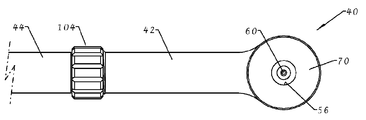
도 2는 본 발명에 따라서 샤워 헤드의 제1구성을 도시한 개략도이다.
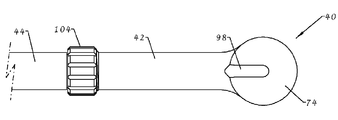
도 3은 본 발명에 따라서 샤워 헤드의 제2구성을 도시한 개략도이다.
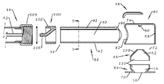
도 4는 도 3의 제2구성에 따라서 샤워 헤드를 제조하기 위한 부품을 도시한 분해 측단면도이다.
도 5는 도 4의 단면선 5-5에 따라서, 도 4의 핸들을 도시한 단면도이다.
도 6은 도 4에 도시한 방향 6으로 바라본 핸들의 단부도이다.
도 7은 도 4에 도시한 단면선 7-7에 따라서, 도 4의 부품들 중 하나를 도시한 단면도이다.
도 8은 부품들이 조립된 것을 제외하고는 도 4와 유사한 도면이다.
도 9는 도 8의 샤워 헤드를 도시한 정면도이다.
도 10은 도 8 및 도 9의 샤워 헤드를 도시한 배면도이다.
도 11은 본 발명에 따라서 샤워 헤드의 제3구성을 도시한 개략도이다.
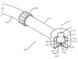
도 12는 도 11의 제3구성에 따라서 샤워 헤드를 도시한 부분 파단 등척도이다.
도 13은 도 11 및 도 12의 제3구성에 따라서 샤워 헤드를 제조하기 위한 부품의 분해 측단면도이다.DESCRIPTION OF THE PREFERRED EMBODIMENTS Hereinafter, specific embodiments of the present invention will be described with reference to the following accompanying drawings, which are presented purely by way of example.
1 is a schematic view showing a shower head according to patent document WO2009 / 056887A1.
2 is a schematic diagram showing a first configuration of a shower head according to the present invention.
3 is a schematic view showing a second configuration of a shower head according to the present invention.
4 is an exploded side cross-sectional view illustrating a part for manufacturing a shower head according to the second configuration of FIG. 3.
FIG. 5 is a cross-sectional view of the handle of FIG. 4, taken along section line 5-5 of FIG. 4.
FIG. 6 is an end view of the handle viewed in the
FIG. 7 is a cross-sectional view showing one of the components of FIG. 4, according to section line 7-7 shown in FIG. 4.
FIG. 8 is a view similar to FIG. 4 except that the parts are assembled.
9 is a front view illustrating the shower head of FIG. 8.
FIG. 10 is a rear view of the shower head of FIGS. 8 and 9.
11 is a schematic diagram showing a third configuration of a shower head according to the present invention.
12 is a partially broken isometric view of the shower head according to the third configuration of FIG. 11.
FIG. 13 is an exploded side sectional view of a part for manufacturing a shower head in accordance with the third configuration of FIGS. 11 and 12;
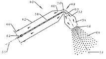
도 2는 본 발명의 예시적 제1구성을 도시한 것으로서, 샤워 헤드(40)는 튜브형 핸들(42)을 구비하며, 이 튜브형 핸들(42)은 그 선단부에서 호스(44)에 연결될 수 있고, 이 호스(44)는 핸들(42)내로 압축공기를 공급하기 위한 용도로 사용된다. 핸들(42)의 타단부에는 벤츄리(48)의 수렴부(46)가 형성된다. 벤츄리(48)의 쓰로트(50)는 벤츄리(48)의 수렴부(46)와 동일한 방향으로 연장되지 않고, 대략 직각으로 굴곡하며, 이후 벤츄리(48)의 확산부(52)는 핸들(42)의 축(55)과 벤츄리(48)의 수렴부(46)에 대해 대략 직각으로 축(53)을 따라서 연장한다. 벤츄리(48)의 확산부(52)는 방출 개구(56)를 구비한 동축 수렴노즐(54)에 연결된다. 방출 개구(56)는 완전한 개구로서 로즈(rose)(류) 등은 없다. 샤워 헤드(40)는 또한 핸들(42)의 구멍 보다는 실질적으로 작은 구멍의 파이프(58)를 포함하며, 이 파이프(58)는 핸들(42)의 선단부로부터 핸들(42) 및 벤츄리(48)의 수렴부(46)를 경유하여 벤츄리(48)의 쓰로트(48)를 통과하면서 대략 직각으로 굴곡하고, 이어서 벤츄리(48)의 확산부(52)의 시작부분에 인근한 개구단부(60)에 도달한다. 파이프(58)의 타단부는 공기 호스(44) 내에서 호스(62)에 결합되도록 배치되며, 여기서 호스(62)는 예를 들면 1 미터 만큼 작은 헤드를 가지고 상대적으로 낮은 압력으로 온수를 공급하기 위한 용도로 사용된다.2 shows a first exemplary configuration of the invention, wherein the
도 2의 구성에 관한 동작을 살펴보면, 공기가 핸들(42)을 경유하여 벤츄리(48)의 수렴부(46)로 이동하며, 수렴부(46)에서 압력하에서 공기가 가속되고 (부피는) 감소되며, 공기 흐름은 벤츄리(48)의 쓰로트(50)에서 대략 직각으로 방향전환하고, 이후 벤추리(48)의 확산부로 진입하며, 확산부에서 공기는 압력하에서 감속되고, (부피가) 증가된다. 온수는 파이프(58)의 단부로부터 공기 흐름 속에 도입된다. 벤츄리(48)의 작용으로 인해, 공기는 파이프(58) 내의 물에 대해 배압(back pressure)을 거의 제공하지 않으며, 실질적으로는 흡입력을 제공하여 파이프(58) 외부로 물이 도출되는 것을 조력하는 작용을 한다. 물이 공기 흐름 속에 수반(합류)됨에 따라서 벤츄리(48)의 확산부(52)에서 물은 파열되어 물방울로 된다. 공기 및 물방물로 이루어진 스트림이 이후 수렴 노즐(54)에서 가속화되며, 이 수렴 노즐(54)은 또한 샤워 헤드(40)에 의해 생성되는 소음을 감소시키는 작용을 하고, 이후 물방울들은 방출 개구(56)로부터 강력한 샤워(분출수)(64)로서 방출된다.Referring to the operation of the configuration of FIG. 2, air travels through the
도 1 및 도 2의 구성을 비교하자면, 도 2의 구성이 보다 더 콤팩트하다.Comparing the configuration of FIGS. 1 and 2, the configuration of FIG. 2 is more compact.
도 2의 구성에 따른 잠재적인 문제점은 벤츄리(48)의 쓰로트(50)의 굴곡부로 인해 벤츄리(48)의 확산부(52)와 수렴 노즐(54)을 통해 물방울의 흐름이 확산부(52)와 수렴노즐(54)의 축에 대해 비대칭적이 되고, 그 결과로 샤워(분출수)(64)가 비대칭적이 된다는 점이다. 도 3의 제2구성은 이러한 잠재적 문제를 회피하는데 목적을 두고 있다.A potential problem according to the configuration of FIG. 2 is that the flow of water droplets through the
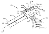
도 3의 예시적 구성에 있어서는, 중공의 대략적 원통 몸체(66)가 설치되고, 핸들(42)의 선단부는 몸체(66)의 측벽(68)을 통과하여 들어간다. 몸체(66)의 전방 단부벽(70)에는 방출 개구(56)가 형성되며, 이 방출 개구(56)의 뒤에서 몸체(66)에는 벤츄리(48)의 수렴노즐(54)과 확산부(52)가 설치된다. 큰 반각(half-angle)을 갖춘 원추대 벽(72)이 확산부(52)의 소직경 단부 둘레에 형성되고 몸체(66)의 후방단부벽(74)으로부터 공간을 두고 이격되어 있으며, 이 공간은 몸체(68)의 축으로 근접하면서 조금씩 감소한다. 원추대 벽(72)의 외경은 원통 몸체(66)의 측벽(68)의 내경 보다 다소 작아서 원추대 벽(72)의 주변(둘레)과 몸체(66)의 측벽(68) 사이에 환형 간극(76)이 형성된다. 원추대 벽(72)의 주변과 몸체(66)의 측벽(68) 간의 환형 간극(76)의 영역(간격 면적)은 핸들(42)을 통과하는 공기 통로의 단면적과 대략 동일하다. 원추대 벽(72)의 주변과 몸체(66)의 후방 단부벽(74) 간의 원통형 간극의 영역은 또한 핸들(42)을 통과하는 공기통로의 단면적과 대략 동일하다. 몸체(66) 내측의 나머지 공간은 플리넘 챔버(plenum chamber)(78)를 형성한다. 사용 중에, 공기는 핸들(42)을 통해 플리넘 챔버(78)로 유입되고, 이어서 환형 간극(76)을 통과하여 원추대 벽(72)과 몸체(66)의 후방 단부 사이의 공간에 도달하며, 이 공간에서 공기는 원추형으로(거의 방사방향으로) 원통 몸체(66)의 축으로 내향한다. 원추대 벽(72)과 후방 단부벽(74) 사이의 공간은 따라서 부분적으로 벽(74)의 원추형상으로 인해 그리고 부분적으로 공기의 방사상 내향 흐름으로 인해 벤츄리(48)의 수렴부(46)를 형성한다. 수렴부(46)와 확산부(52) 사이의 전이부는 벤츄리(48)의 쓰로트(50)를 형성하며, 이 쓰로트에서 공기는 대략 직각으로 방향전환한다. 몸체(68)의 후방 단부벽(74)은 중심 부근에서 모따기가 되어 벤츄리(48)의 쓰로트(50)에서 공기 흐름이 방향전환하는 것을 조력한다. 워터 파이프(58)는 몸체(68) 부근에서 핸들(42)의 벽을 뚫고 나와 몸체(68)의 뒤(후방단부)에 도달하며, 여기서 워터 파이프(58)는 몸체(68)의 후방 단부벽(74) 중앙을 통과하여 진입하며, 여기서 파이프(58)의 단부(60)는 벤츄리(48)의 확산부(52)의 시작부분에 인근하여 위치하는 한편 벤츄리(48)의 확산부(52)와 수렴노즐(54)과는 동축을 이룬다.In the exemplary configuration of FIG. 3, a hollow approximately cylindrical body 66 is installed and the tip of the
도 3의 구성에 있어서 공기 흐름은 따라서 호스(44)로부터 핸들(42)을 경유하여 플리넘 챔버(78)로 진행한다. 플리넘 챔버(78)로부터 공기는 환형 간극(76)을 경유하여 벤츄리(48)의 수렴부(46)로 유입되며, 수렴부(46)에서 공기는 원추형으로, 거의 방사상 내향 방향으로[도 3에서 2점 쇄선(79)으로 표시한 일반적, 전체적인 방향으로] 흐르며, 원추대 벽(72)과 몸체(66)의 후방 단부벽(74) 사이의 공간이 좁혀짐으로 인해, 그리고 공기 흐름의 원추형 또는 방사상의 특성으로 인해 공기의 흐름은 가속된다. 공기는 이후 쓰로트(50)에서 벤츄리(48)의 확산부(52)로 방향전환된다. 한편, 온수는 호스(62)로부터 파이프(58)로 흘러서 벤츄리(48)의 확산부(52) 시작부분에 위치하는 파이프(58)의 단부(60)에서 공기 흐름에 도입된다. 다시, 벤츄리(48)의 작용으로 인해, 공기는 파이프(58) 내의 물에 대해 배압(back pressure)을 제공하지 않고 오히려 흡입력을 제공하여 파이프(58)로부터 물이 도출되는 것을 조력한다. 물은 공기 흐름에 합류함에 따라서, 벤츄리(48)의 확산부(52)에서 물방울로 분열한다. 공기와 물로 이루어진 스트림은 이후 수렴 노즐(54)에서 가속화되며, 여기서 수렴 노즐(54)은 또한 샤워 헤드(40)에 의해 생성된 소음을 감소시키는 작용을 하며, 이후 물방울은 방출 개구(56)로부터 강력한 샤워(분출수)(64)로서 방출된다. 공기가 모든 방사방향으로부터 대략 균일하게 벤츄리(48)의 쓰로트(50)로 흐르기 때문에, 벤츄리(48)의 확산부(52), 수렴 노즐(54), 및 방출 개구(56)를 경유하는 공기와 물방울의 흐름은 대체적으로 대칭적이 된다.In the configuration of FIG. 3 the air flow thus proceeds from the
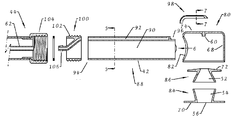
도 3의 제2구성에 따른 본 발명의 일실시예에 대하여 도 4 내지 도 10을 참조하여 보다 상세히 설명한다.An embodiment of the present invention according to the second configuration of FIG. 3 will be described in more detail with reference to FIGS. 4 to 10.
일반적으로 일측 개방 단부를 구비한 원통 형태의 제1플라스틱 성형체(80)가 측벽(68)과 후방 단부벽(74)을 형성한다. 성형체(80)의 측벽(68)에는 큰 구멍(82)이 형성되어 있어 핸들(42)을 수용하고, 후방 단부벽(74)의 중앙에는 작은 구멍이 형성되어 물 통로의 단부(60)를 제공한다. 제2플라스틱 성형체(84)는 전방 단부벽(70), 방출 개구(56), 및 수렴 노즐(54)을 제공한다. 제3플라스틱 성형체(86)는 벤츄리(48)의 확산부(52)와 원추대 벽(72)을 제공한다. 제1성형체(80), 제2성형체(84), 및 제3성형체(86)는 도 8에 도시한 구성에 함께 고정된다.In general, the cylindrical first plastic molded
제4플라스틱 성형체(88)가 핸들(48)을 제공한다. 이 성형체(88)는 일반적으로 튜브형으로서 핸들(42)을 통과하는 공기 통로(90)를 제공한다. 그러나, 성형체(88)의 벽은 일부에서는 두껍고, 핸들(42)의 후단부(94)로부터 거의 전단부(96)까지 연장된 온수용 (물) 통로(92)가 형성되어 있다. 선단부에서 통로는 핸들(42)의 벽을 통과하여 외부로 나온다. 이 핸들(42)의 선단부(96)는 제1성형체(80)의 측벽(68)의 구멍(82)에 고정되고, 일정 범위로 플리넘 챔버(78) 내로 돌출한다.Fourth plastic molded
제5플라스틱 성형체(98)는 L자형 채널의 형태를 구비하고 제1성형체(80)에 고정되어 있어, 도 8에 도시한 바와 같이, 핸들에서의 물 통로(92)와 벤츄리(48)에서의 물 통로의 단부(60)는 서로 연통된다.The fifth plastic molded
제6플라스틱 성형체(100)는 핸들(42)의 후단부(94)에 고정된다. 이 성형체(100)는 스크류 나사부(102) 및 니플(106)을 제공하며, 스크류 나사부(102)에는 공기 호스(44)의 커플링부(104)가 연결될 수 있고, 니플(106)은 물 통로(92)와 연통하는 한편, 공기 호스(44) 내측에 위치하는 온수 호스(62)에 정합될 수 있다.The sixth plastic molded
샤워 헤드의 예시적인 제3구성에 대하여 도 11 내지 도 13을 참조하여 설명하다. 제3구성은 다음 사항을 제외하고는 제2구성과 유사하다.An exemplary third configuration of the shower head will be described with reference to FIGS. 11 to 13. The third configuration is similar to the second configuration except for the following.
첫째, 벤츄리(48)의 수렴부(46)와 확산부(52) 그리고 수렴 노즐(54)이 도 1 내지 도 10의 제1구성 및 제2구성에서 보다 더 가파르게 수렴 또는 확산된다. 이러한 구조는 단일 원추대 벽부(108)가 (i) 내측면에서 벤츄리(48)의 확산부(52)를 제공하는 것과 (ii)외측면에서 벤츄리(48)의 수렴부(46)의 벽들 중 하나를 제공하는 것을 편리하게 가능하게 하면서도, 벤츄리(48)의 수렴부(46)의 타측벽이 여전히 후방 단부벽(74)에 의해 제공될 수 있도록 한다.First, the converging
둘째, 벤츄리(48)의 확산부(52)와 수렴 노즐(54) 사이에 원통형 덕트부(110)가 설치된다.Second, the
도 11 및 도 12에 도시하지는 않았지만, 핸들(42)의 후단부에 또는 플리넘 챔버(78)에 배플이 설치되어 핸들(42)에 최근접한 벤츄리(48)의 수렴부(46)의 후단부로부터 멀리 공기를 편향시킬 수도 있다.Although not shown in FIGS. 11 and 12, a baffle is provided at the rear end of the
도 2, 도 3 내지 도 10, 및 도 11 내지 도 13의 어느 구성과 함께, 공기 호스(44)가 가변 속도를 가진 전기모터에 의해 구동되는 송풍기(air blower)에 연결된다. 온수 호스(62)는 자동 온도 조절 장치로 제어될 수 있는 냉온 혼합기 밸브에 연결된다. 시스템에는 여기에 참조로 포함되는 특허문헌 WO2009/056887A1에 설명된 기타 특징요소가 설치될 수도 있다.2, 3 to 10, and 11 to 13, the
상기 설명한 구성에 대해 많은 변형 및 개량이 가능하다.Many modifications and improvements are possible to the configurations described above.
예를 들면, 욕조 위의 샤워 공간(박스)에서 벽에 샤워 헤드(40)을 착탈가능하게 장착하기 위해 브라켓을 설치할 수도 있고, 브라켓과 결합하기 위해 핸들(42)을 적절히 형성할 수도 있다.For example, a bracket may be installed to detachably mount the
도 2에서는 벤츄리(48)의 수렴부(46)와 확산부(52)에서 공기 흐름 방향의 축들이 상호 직각으로 위치하고, 도 3에서, 벤츄리(48)의 수렴부(46)에서의 공기 흐름의 전체 평면이 벤츄리(48)의 확산부(52)에서 공기 흐름 방향의 축에 대해 대략 직각으로 위치하지만, 직각 이외의 다른 각도를 적용할 수도 있으며, 예를 들면, 60°내지 120°사이의 각도, 또는 심지어 45°내지 135°사이의 각도를 적용할 수도 있다.In FIG. 2, the axes of the air flow directions at the converging
이상과 같이 본 발명의 실시예에 대하여 단지 예시를 위해 설명하였으며, 본 발명의 범위 내에서 많은 변형 및 개량이 가능함은 자명한 것이다.As described above, only the embodiments of the present invention have been described for the purpose of illustration, and many modifications and improvements are possible within the scope of the present invention.
Claims (18)
수렴부(46), 쓰로트(50) 및 확산부(52)를 구비한 벤츄리(48)를 통해, 압축 공기 공급기로부터 샤워 방출 개구(56)로 흐르는 압축 공기의 흐름을 위한 공기 통로와;
물 공급기로부터 상기 벤츄리에 위치한 물 방출 개구(60)로 흐르는 물의 흐름을 위한 물 통로(58;92);
를 포함하고,
상기 벤츄리는 사용중에, 공기 흐름의 전체 방향이 벤츄리에서 실질적 각도로 방향전환 되도록 구성된 것을 특징으로 하는
샤워 헤드.As shower head 40:
An air passage for the flow of compressed air from the compressed air supply to the shower discharge opening 56 through a venturi 48 having a converging portion 46, a throat 50, and a diffusion portion 52;
A water passage (58; 92) for the flow of water from the water supply to the water discharge opening (60) located in the venturi;
Lt; / RTI >
The venturi is configured such that during use, the entire direction of the air flow is redirected at a substantial angle in the venturi.
Shower head.
상기 공기 흐름의 전체 방향은 상기 벤츄리의 쓰로트에서 또는 쓰로트에 인근한 곳에서 상기 실질적 각도로 방향전환하는 것을 특징으로 하는
샤워 헤드.The method of claim 1,
Wherein the overall direction of the air flow is redirected at the substantially angle at or near the throat of the venturi.
Shower head.
상기 벤츄리는 사용중에, 상기 벤츄리의 확산부에서 공기 흐름의 전체 방향이 축(53) 방향을 따르도록 구성된 것을 특징으로 하는
샤워 헤드.3. The method according to claim 1 or 2,
In use the venturi is characterized in that the entire direction of the air flow in the diffusion of the venturi is along the axis 53 direction.
Shower head.
상기 벤츄리는 사용중에, 상기 벤츄리의 상기 수렴부에서 공기 흐름의 전체 방향이 상기 벤츄리의 상기 확산부의 흐름 축에 대해 상기 실질적 각도로 위치하는 축(55) 방향을 따르도록 구성된 것을 특징으로 하는
샤워 헤드.The method of claim 3,
In use, the venturi is configured such that the overall direction of air flow at the converging portion of the venturi is along the direction of the axis 55 located at the substantially angle with respect to the flow axis of the diffusion portion of the venturi.
Shower head.
상기 샤워 헤드는 상기 공기 공급기에 연결하기 위한 후단부를 구비한 길다란 핸들(42)을 포함하고;
상기 벤츄리의 수렴부는 상기 핸들의 선단부에 인근하여 배치되는 한편 상기 핸들과 실질적으로 정렬되고;
상기 공기 통로는 상기 핸들의 후단부로 부터 상기 벤츄리의 수렴부로 상기 핸들을 통해 연장되는 것을 특징으로 하는
샤워 헤드. 5. The method of claim 4,
The shower head comprises an elongated handle 42 having a rear end for connecting to the air supply;
A converging portion of the venturi is disposed near the leading end of the handle and substantially aligned with the handle;
The air passage extends through the handle from the rear end of the handle to the convergence portion of the venturi;
Shower head.
상기 벤츄리는 사용중에, 상기 벤츄리의 수렴부에서 상기 공기 흐름의 전체 방향이 방사상 원추형으로 상기 벤츄리의 상기 쓰로트를 향하도록 구성된 것을 특징으로 하는
샤워 헤드.The method of claim 3,
The venturi is in use, characterized in that the entire direction of the air flow at the converging portion of the venturi is directed toward the throat of the venturi in a radial cone shape.
Shower head.
상기 샤워 헤드는 후방벽(74)을 구비한 하우징을 포함하고;
상기 하우징 내에서는 원추대 벽(72; 108)이 배치되고, 상기 원추대 벽은 상기 후방벽을 향하는 방향으로 테이퍼 형태로 형성되면서, 상기 후방벽으로부터 공간을 두고 이격되어 있으며,
상기 벤츄리의 상기 수렴부는 상기 후방벽과 상기 원추대 벽의 외측면 사이에 배치되고,
상기 벤츄리의 상기 쓰로트는 상기 후방벽과 상기 원추대 벽의 소직경 단부 사이에서 적어도 부분적으로 배치되는 것을 특징으로 하는
샤워 헤드.The method according to claim 6,
The shower head comprises a housing having a rear wall (74);
A conical wall 72 (108) is disposed in the housing, and the conical wall is tapered in a direction toward the rear wall, spaced apart from the rear wall with a space.
The converging portion of the venturi is disposed between the rear wall and an outer surface of the conical wall,
The throat of the venturi is at least partially disposed between the rear wall and the small diameter end of the conical wall
Shower head.
상기 벤츄리의 상기 확산부는 상기 원추대 벽(108)의 내면에 의해 형성되는 것을 특징으로 하는
샤워 헤드.8. The method of claim 7,
The diffuser of the venturi is formed by the inner surface of the cone wall 108.
Shower head.
상기 공기 통로는 상기 벤츄리의 상기 수렴부의 상류에 위치하는 플리넘 챔버(plenum chamber)(78)를 포함하는 것을 특징으로 하는
샤워 헤드.9. The method of claim 8,
The air passage comprises a plenum chamber 78 located upstream of the converging portion of the venturi.
Shower head.
상기 샤워 헤드는 상기 공기 공급기에 연결하기 위한 후단부를 구비한 길다란 핸들(42)을 포함하고;
상기 플리넘 챔버는 상기 핸들의 선단부에 인근하여 배치되고;
상기 공기 통로는 상기 핸들의 후단부로부터 상기 플리넘 챔버로 상기 핸들을 통해 연장되는 것을 특징으로 하는
샤워 헤드.10. The method of claim 9,
The shower head comprises an elongated handle 42 having a rear end for connecting to the air supply;
The plenum chamber is disposed proximate the tip of the handle;
The air passage extends through the handle from the rear end of the handle to the plenum chamber
Shower head.
상기 플리넘 챔버는 상기 벤츄리의 확산부를 둘러싸는 것을 특징으로 하는
샤워 헤드.11. The method of claim 10,
The plenum chamber surrounds the diffuser of the venturi.
Shower head.
상기 실질적 각도는 45°내지 135°사이의 각도인 것을 특징으로 하는
샤워 헤드.12. The method according to any one of claims 1 to 11,
The substantially angle is characterized in that the angle between 45 ° to 135 °
Shower head.
상기 물 방출 개구는 상기 벤츄리의 쓰로트에 배치되는 것을 특징으로 하는
샤워 헤드.13. The method according to any one of claims 1 to 12,
The water discharge opening is arranged in a throat of the venturi.
Shower head.
상기 물 방출 개구는 상기 벤츄리의 상기 확산부의 시작부분에 또는 시작부분 인근에 배치되는 것을 특징으로 하는
샤워 헤드.13. The method according to any one of claims 1 to 12,
The water discharge opening is arranged at or near the beginning of the diffusion of the venturi
Shower head.
상기 벤츄리의 상기 확산부 하류에 위치하는 수렴 노즐(54)을 더 포함하는 것을 특징으로 하는
샤워 헤드.15. The method according to any one of claims 1 to 14,
Further comprising a converging nozzle 54 positioned downstream of said diffusion of said venturi.
Shower head.
상기 샤워 헤드에는 상기 샤워 방출 개구 인근에 위치하는 로즈(rose) 류가 설치되지 않은 것을 특징으로 하는
샤워 헤드. 16. The method according to any one of claims 1 to 15,
The shower head is characterized in that no rose (rose) located in the vicinity of the shower discharge opening is installed
Shower head.
상기 제1항 내지 제16항 중 어느 한 항에 따른 샤워 헤드와;
송풍기와;
상기 송풍기를 상기 샤워 헤드의 공기 통로에 연결하기 위한 가요성 공기 호스(44);
를 포함하는 것을 특징으로 하는
샤워 장치.As a shower device:
A shower head according to any one of claims 1 to 16;
Blower;
A flexible air hose (44) for connecting the blower to the air passage of the shower head;
≪ RTI ID = 0.0 >
Shower device.
상기 샤워 헤드의 물 통로에 물 공급기를 연결하기 위해 가요성 물 호스(62)가 배치되고;
상기 물 호스는 상기 공기 호스 내에서 상기 샤워 헤드로 연장되는 것을 특징으로 하는
샤워 장치.19. The method of claim 18,
A flexible water hose 62 is arranged to connect a water supply to the water passage of the shower head;
The water hose extends into the shower head in the air hose
Shower device.
Applications Claiming Priority (3)
| Application Number | Priority Date | Filing Date | Title |
|---|---|---|---|
| GB1102766.1A GB2488144B (en) | 2011-02-17 | 2011-02-17 | Shower head |
| GB1102766.1 | 2011-02-17 | ||
| PCT/GB2012/050304 WO2012110790A1 (en) | 2011-02-17 | 2012-02-10 | Shower head |
Publications (1)
| Publication Number | Publication Date |
|---|---|
| KR20140033345A true KR20140033345A (en) | 2014-03-18 |
Family
ID=43859558
Family Applications (1)
| Application Number | Title | Priority Date | Filing Date |
|---|---|---|---|
| KR1020137024378A KR20140033345A (en) | 2011-02-17 | 2012-02-10 | Shower head |
Country Status (15)
| Country | Link |
|---|---|
| US (1) | US9855569B2 (en) |
| EP (1) | EP2675568B1 (en) |
| JP (1) | JP6026435B2 (en) |
| KR (1) | KR20140033345A (en) |
| CN (1) | CN103379964B (en) |
| AU (1) | AU2012216911B2 (en) |
| BR (1) | BR112013020861A2 (en) |
| CA (1) | CA2826736A1 (en) |
| GB (1) | GB2488144B (en) |
| HK (1) | HK1185580A1 (en) |
| MX (1) | MX352860B (en) |
| MY (1) | MY170443A (en) |
| RU (1) | RU2013139690A (en) |
| WO (1) | WO2012110790A1 (en) |
| ZA (1) | ZA201306157B (en) |
Families Citing this family (7)
| Publication number | Priority date | Publication date | Assignee | Title |
|---|---|---|---|---|
| CN104759363A (en) * | 2015-03-24 | 2015-07-08 | 安徽全盛机械有限公司 | Energy-saving centrifuge nozzle |
| GB2553110A (en) * | 2016-08-22 | 2018-02-28 | Kelda Showers Ltd | Shower head producing a suspension of water droplets in air |
| JP6423495B1 (en) * | 2017-07-21 | 2018-11-14 | 株式会社メンテック | NOZZLE CAP, NOZZLE DEVICE PROVIDED WITH THE SAME |
| CN109465122A (en) * | 2019-01-10 | 2019-03-15 | 广东万家乐燃气具有限公司 | A kind of oxygen-enriched shower and water heater |
| GB202005441D0 (en) | 2020-04-14 | 2020-05-27 | Kelda Showers Ltd | Shower head and method of operation to produce a suspension of water droplets in air |
| GB202103024D0 (en) | 2021-03-03 | 2021-04-14 | Kelda Showers Ltd | Water outlet fitting, e.g. tap or shower head, producing a combined flow of gas and water, and power connector therefor |
| GB2612790A (en) | 2021-11-10 | 2023-05-17 | Kelda Showers Ltd | Water outlet fitting, e.g. shower head or tap, producing water bubbles |
Family Cites Families (26)
| Publication number | Priority date | Publication date | Assignee | Title |
|---|---|---|---|---|
| FR683612A (en) | 1929-01-28 | 1930-06-16 | Neu Sa | Low pressure compressed air water sprayer allowing the use of a fan instead of a compressor |
| US2026743A (en) | 1934-11-26 | 1936-01-07 | Clinton J Kurtz | Spray nozzle |
| US3281864A (en) | 1963-07-29 | 1966-11-01 | Hildegarde B Linnehan | Portable bathing appliance for therapeutic use |
| US3568668A (en) | 1969-06-04 | 1971-03-09 | Harry B Neis | Automatic shower assembly |
| FR2259576A1 (en) | 1972-08-16 | 1975-08-29 | Baker Larry | Low water consumption washing apparatus such as shower - includes water source, pressurized gas source and device for carrying water droplets on gas flow to generate high pressure cleaning water jet |
| US4134547A (en) | 1976-12-14 | 1979-01-16 | O. Ditlev-Simonsen, Jr. | Jet pipe |
| US4341347A (en) * | 1980-05-05 | 1982-07-27 | S. C. Johnson & Son, Inc. | Electrostatic spraying of liquids |
| US4426040A (en) | 1981-06-04 | 1984-01-17 | Smith Lewis L | Adjustable aerating shower head |
| JP2830432B2 (en) | 1990-09-11 | 1998-12-02 | 松下電器産業株式会社 | Shower equipment |
| JPH09262512A (en) | 1996-01-26 | 1997-10-07 | Mitsubishi Electric Corp | Gas-liquid jetting machine and its operation method |
| DE19813366C2 (en) | 1997-04-02 | 2002-12-05 | Hartmut Wolf | shower head |
| JP2000237082A (en) * | 1999-02-17 | 2000-09-05 | Toto Ltd | Air mixing shower head |
| JP2001149252A (en) | 1999-11-29 | 2001-06-05 | Takara Belmont Co Ltd | Foaming shower device |
| JP2002119435A (en) * | 2000-10-13 | 2002-04-23 | Toto Ltd | Foam shower device |
| US6992378B2 (en) | 2000-12-30 | 2006-01-31 | Intel Corporation | Socket and package power/ground bar apparatus that increases current carrying capacity resulting in higher IC power delivery |
| JP2002272805A (en) * | 2001-03-15 | 2002-09-24 | Toto Ltd | Blood circulation stimulation shower |
| JP2006116518A (en) | 2004-10-25 | 2006-05-11 | Fujio Negoro | Shower for generating microbubble |
| DE102005048489A1 (en) * | 2005-10-07 | 2007-04-19 | Dieter Prof. Dr.-Ing. Wurz | Two-fluid nozzle with annular gap atomization |
| DE102006009147A1 (en) * | 2006-02-24 | 2007-08-30 | Wurz, Dieter, Prof. Dr.-Ing. | Dual nozzle has mixing chamber, and ring is arranged by secondary air nozzles around mouth of main nozzle |
| WO2007124455A2 (en) | 2006-04-20 | 2007-11-01 | Water Pik, Inc. | Converging spray showerhead |
| JP2007326082A (en) | 2006-06-09 | 2007-12-20 | Takara Belmont Co Ltd | Shower head |
| GB2454228B (en) * | 2007-11-01 | 2011-08-03 | Rapro Emulations Ltd | Shower head and shower apparatus |
| US20090202293A1 (en) * | 2008-02-12 | 2009-08-13 | Peter Kajuch | Air induction showerhead ball joint |
| CN201313083Y (en) | 2008-08-07 | 2009-09-23 | 张藤予 | Gas-water mixed water-saving shower device |
| DE202011001711U1 (en) | 2011-01-19 | 2011-04-21 | Delvac Sanitär GmbH | Device for the discharge of water with the addition of air, as well as a shower or hand shower |
| CN202174022U (en) * | 2011-07-11 | 2012-03-28 | 陶正年 | Low-water-pressure anti-blocking shower with single water outlet hole |
-
2011
- 2011-02-17 GB GB1102766.1A patent/GB2488144B/en not_active Expired - Fee Related
-
2012
- 2012-02-10 AU AU2012216911A patent/AU2012216911B2/en not_active Ceased
- 2012-02-10 MY MYPI2013002892A patent/MY170443A/en unknown
- 2012-02-10 CA CA2826736A patent/CA2826736A1/en not_active Abandoned
- 2012-02-10 JP JP2013554003A patent/JP6026435B2/en not_active Expired - Fee Related
- 2012-02-10 KR KR1020137024378A patent/KR20140033345A/en not_active Application Discontinuation
- 2012-02-10 BR BR112013020861A patent/BR112013020861A2/en not_active Application Discontinuation
- 2012-02-10 EP EP12705708.1A patent/EP2675568B1/en active Active
- 2012-02-10 US US13/985,637 patent/US9855569B2/en not_active Expired - Fee Related
- 2012-02-10 MX MX2013009534A patent/MX352860B/en active IP Right Grant
- 2012-02-10 RU RU2013139690/05A patent/RU2013139690A/en not_active Application Discontinuation
- 2012-02-10 CN CN201280009000.7A patent/CN103379964B/en active Active
- 2012-02-10 WO PCT/GB2012/050304 patent/WO2012110790A1/en active Application Filing
-
2013
- 2013-08-15 ZA ZA2013/06157A patent/ZA201306157B/en unknown
- 2013-11-19 HK HK13112932.1A patent/HK1185580A1/en not_active IP Right Cessation
Also Published As
| Publication number | Publication date |
|---|---|
| AU2012216911A1 (en) | 2013-08-22 |
| AU2012216911B2 (en) | 2017-04-13 |
| MY170443A (en) | 2019-07-31 |
| RU2013139690A (en) | 2015-04-10 |
| JP2014508592A (en) | 2014-04-10 |
| US9855569B2 (en) | 2018-01-02 |
| MX2013009534A (en) | 2014-04-25 |
| EP2675568A1 (en) | 2013-12-25 |
| GB201102766D0 (en) | 2011-03-30 |
| HK1185580A1 (en) | 2014-02-21 |
| WO2012110790A1 (en) | 2012-08-23 |
| US20130320112A1 (en) | 2013-12-05 |
| ZA201306157B (en) | 2014-04-30 |
| CA2826736A1 (en) | 2012-08-23 |
| JP6026435B2 (en) | 2016-11-16 |
| BR112013020861A2 (en) | 2016-09-27 |
| GB2488144B (en) | 2014-01-15 |
| CN103379964B (en) | 2016-06-01 |
| EP2675568B1 (en) | 2020-04-08 |
| MX352860B (en) | 2017-12-13 |
| CN103379964A (en) | 2013-10-30 |
| GB2488144A (en) | 2012-08-22 |
Similar Documents
| Publication | Publication Date | Title |
|---|---|---|
| KR20140033345A (en) | Shower head | |
| US20100252658A1 (en) | Shower Arrangement | |
| US20130199640A1 (en) | Fixture for a sink | |
| TW200940020A (en) | Air induction showerhead ball joint | |
| US4422191A (en) | Hydrotherapy jet for tubs, spas or pools | |
| US20110108640A1 (en) | Shower head for a sanitary shower fitting | |
| CA2344185A1 (en) | Nozzle for fluid dispenser | |
| JP2012523511A (en) | Air inductor | |
| CN102216535B (en) | Water saving plug | |
| CN108636625A (en) | Multi-mode fluid tip | |
| RU2012119994A (en) | FOAM FORMER FOR FIRE HOSES | |
| JP3208970U (en) | Aspirator device for shower head | |
| US20070056639A1 (en) | Aspirator for a shower fitting | |
| CA2959840C (en) | Power sprayer | |
| JPH11222890A (en) | Faucet device for city water | |
| KR200425310Y1 (en) | A shower have water saving device | |
| KR200266540Y1 (en) | Shower head for mixing gas in water under the low pressure | |
| US9974709B2 (en) | Nozzles | |
| WO2020005529A1 (en) | Jet nozzle | |
| GB2440745A (en) | Vortex Water Feature | |
| JPH06225916A (en) | Jet nozzle for bathtub |
Legal Events
| Date | Code | Title | Description |
|---|---|---|---|
| E902 | Notification of reason for refusal | ||
| E601 | Decision to refuse application |