KR20140026401A - Wireless communications device including side-by-side passive loop antennas and related methods - Google Patents
Wireless communications device including side-by-side passive loop antennas and related methods Download PDFInfo
- Publication number
- KR20140026401A KR20140026401A KR1020137026727A KR20137026727A KR20140026401A KR 20140026401 A KR20140026401 A KR 20140026401A KR 1020137026727 A KR1020137026727 A KR 1020137026727A KR 20137026727 A KR20137026727 A KR 20137026727A KR 20140026401 A KR20140026401 A KR 20140026401A
- Authority
- KR
- South Korea
- Prior art keywords
- antenna
- passive
- antennas
- loop
- passive loop
- Prior art date
Links
Images


Classifications
-
- H—ELECTRICITY
- H01—ELECTRIC ELEMENTS
- H01Q—ANTENNAS, i.e. RADIO AERIALS
- H01Q7/00—Loop antennas with a substantially uniform current distribution around the loop and having a directional radiation pattern in a plane perpendicular to the plane of the loop
-
- H—ELECTRICITY
- H01—ELECTRIC ELEMENTS
- H01Q—ANTENNAS, i.e. RADIO AERIALS
- H01Q1/00—Details of, or arrangements associated with, antennas
- H01Q1/12—Supports; Mounting means
- H01Q1/22—Supports; Mounting means by structural association with other equipment or articles
- H01Q1/24—Supports; Mounting means by structural association with other equipment or articles with receiving set
- H01Q1/241—Supports; Mounting means by structural association with other equipment or articles with receiving set used in mobile communications, e.g. GSM
- H01Q1/242—Supports; Mounting means by structural association with other equipment or articles with receiving set used in mobile communications, e.g. GSM specially adapted for hand-held use
- H01Q1/243—Supports; Mounting means by structural association with other equipment or articles with receiving set used in mobile communications, e.g. GSM specially adapted for hand-held use with built-in antennas
-
- H—ELECTRICITY
- H01—ELECTRIC ELEMENTS
- H01Q—ANTENNAS, i.e. RADIO AERIALS
- H01Q21/00—Antenna arrays or systems
- H01Q21/06—Arrays of individually energised antenna units similarly polarised and spaced apart
-
- H—ELECTRICITY
- H01—ELECTRIC ELEMENTS
- H01Q—ANTENNAS, i.e. RADIO AERIALS
- H01Q21/00—Antenna arrays or systems
- H01Q21/06—Arrays of individually energised antenna units similarly polarised and spaced apart
- H01Q21/061—Two dimensional planar arrays
-
- H—ELECTRICITY
- H01—ELECTRIC ELEMENTS
- H01Q—ANTENNAS, i.e. RADIO AERIALS
- H01Q5/00—Arrangements for simultaneous operation of antennas on two or more different wavebands, e.g. dual-band or multi-band arrangements
- H01Q5/30—Arrangements for providing operation on different wavebands
- H01Q5/378—Combination of fed elements with parasitic elements
- H01Q5/385—Two or more parasitic elements
-
- Y—GENERAL TAGGING OF NEW TECHNOLOGICAL DEVELOPMENTS; GENERAL TAGGING OF CROSS-SECTIONAL TECHNOLOGIES SPANNING OVER SEVERAL SECTIONS OF THE IPC; TECHNICAL SUBJECTS COVERED BY FORMER USPC CROSS-REFERENCE ART COLLECTIONS [XRACs] AND DIGESTS
- Y10—TECHNICAL SUBJECTS COVERED BY FORMER USPC
- Y10T—TECHNICAL SUBJECTS COVERED BY FORMER US CLASSIFICATION
- Y10T29/00—Metal working
- Y10T29/49—Method of mechanical manufacture
- Y10T29/49002—Electrical device making
- Y10T29/49016—Antenna or wave energy "plumbing" making
Abstract
무선 통신 디바이스는 하우징, 및 하우징에 의해 적재된 무선 통신 회로를 포함할 수 있다. 무선 통신 디바이스는 또한 하우징에 의해 적재되고 무선 통신 회로에 결합된 안테나 조립체를 포함할 수 있다. 안테나 조립체는 기판 및 기판에 의해 적재되고 사이드-바이 사이드 관계로 배열된 복수의 수동 루프 안테나를 포함할 수 있다. 복수의 떨어져 이격된 수동 루프 안테나 각각은 수동 루프 전도체 및 그것에 결합된 튜닝 부재를 포함할 수 있다. 안테나 조립체는 또한 기판에 의해 적재되고 복수의 수동 루프 안테나 각각과 적어도 부분적으로 같은 공간을 차지하도록 배열된 능동 루프 안테나를 포함할 수 있다. 능동 루프 안테나는 능동 루프 전도체 및 내부에 형성된 한 쌍의 피드포인트를 포함할 수 있다.The wireless communication device can include a housing and wireless communication circuitry loaded by the housing. The wireless communication device may also include an antenna assembly loaded by the housing and coupled to the wireless communication circuit. The antenna assembly may include a substrate and a plurality of passive loop antennas loaded by the substrate and arranged in a side-by-side relationship. Each of the plurality of spaced apart passive loop antennas may include a passive loop conductor and a tuning member coupled thereto. The antenna assembly may also include an active loop antenna loaded by the substrate and arranged to occupy at least partially the same space as each of the plurality of passive loop antennas. The active loop antenna may include an active loop conductor and a pair of feed points formed therein.
Description
본 발명은 통신의 분야, 그리고, 더 구체적으로, 안테나 및 관련된 방법에 관한 것이다.The present invention relates to the field of communications and, more particularly, to antennas and related methods.
안테나는 통신 또는 내비게이션과 같은 다양한 목적을 위해 사용될 수 있고, 휴대용 라디오 디바이스는 방송 수신기, 호출기, 또는 무선 측위 디바이스("ID 태그")를 포함할 수 있다. 셀룰러 전화기는 매우 흔한 무선 통신 디바이스의 일례이다. 상대적으로 작은 크기, 증가된 효율성, 및 상대적으로 넓은 방사 패턴은 휴대용 라디오 또는 무선 디바이스용 안테나에 일반적으로 요구되는 특징이다. 부가적으로, 무선 디바이스의 기능성이 계속적으로 증가함에 따라서, 사용자가 이동하기에 더 쉽고 더 편리한 더 작은 무선 디바이스에 대한 요구 역시 증가한다. 무선 디바이스 제조자에게 이것이 야기하는 하나의 도전은 안테나를 위해 이용가능한, 상대적으로 제한된 양의 공간 내에 요구되는 작동 특징을 제공하는 안테나를 설계하는 것이다. 예를 들어, 안테나가 다중 주파수 대역에 걸쳐 그리고 더 낮은 주파수에서 통신하는 것이 요구될 수 있다. The antenna may be used for various purposes such as communication or navigation, and the portable radio device may include a broadcast receiver, pager, or radio location device (“ID tag”). Cellular telephones are one example of a very common wireless communication device. Relatively small size, increased efficiency, and relatively wide radiation pattern are features typically required for antennas for portable radios or wireless devices. Additionally, as the functionality of wireless devices continues to increase, so does the need for smaller wireless devices that are easier and more convenient for users to move around. One challenge this brings to wireless device manufacturers is to design an antenna that provides the required operating characteristics within a relatively limited amount of space available for the antenna. For example, it may be required for the antenna to communicate over multiple frequency bands and at lower frequencies.
더 새로운 설계 및 제조 기법은 전자 부품을 상대적으로 작은 크기로 이끌어서 많은 무선 통신 디바이스와 시스템의 크기를 감소시켰다. 불행히도, 안테나, 그리고 특히, 광대역 안테나는 비교가능한 수준으로 크기를 감소시키지 못해서 종종 더 작은 통신 디바이스에 사용되는 더 큰 부품 중 하나이다.Newer design and manufacturing techniques have led electronic components to be relatively small, reducing the size of many wireless communication devices and systems. Unfortunately, antennas, and in particular broadband antennas, do not reduce their size to comparable levels and are therefore one of the larger components often used in smaller communication devices.
실제로, 안테나 크기는 작동 주파수 또는 주파수들에 기반할 수 있다. 예를 들어, 안테나는 작동 주파수가 감소함에 따라서 점점 더 커질 수 있다. 파장을 감소시키는 것은 안테나의 크기를 감소시킬 수 있지만, 더 긴 파장이 전파 향상을 위해 요구될 수 있다. 장-범위 통신에 사용되는, 고주파수(HF), 예를 들어 3 내지 30 MHz에서, 효율적인 안테나, 예를 들어, 송신 안테나는 너무 커서 휴대가능하지 않을 수 있고, 고정국에서 유선 안테나가 요구될 수 있다. 따라서, 단지 안테나 크기를 감소시킬 뿐만 아니라, 요구되는 주파수 대역에 걸쳐 최소 영역에 대해 최대 이득을 갖는 감소된 크기의 안테나를 설계하고 제조하는 것 역시 이들 무선 통신 어플리케이션에서 점점 더 중요해질 수 있다. In practice, antenna size may be based on operating frequency or frequencies. For example, the antenna may grow larger as the operating frequency decreases. Reducing the wavelength can reduce the size of the antenna, but longer wavelengths may be required to improve propagation. At high frequencies (HF), for example 3 to 30 MHz, used for long-range communication, efficient antennas, for example transmit antennas, may be too large and not portable, and wired antennas may be required in fixed stations. . Thus, not only reducing the antenna size, but also designing and manufacturing an antenna of reduced size with maximum gain over a minimum area over the required frequency band may also become increasingly important in these wireless communication applications.
전기적으로 작은 안테나의 순시 3 dB 이득 대역폭(반전력 고정 튜닝 방사 대역폭으로도 알려짐)은 추-해링턴 한계(Chu-Harrington limit) 하에 제한되는 것으로 간주된다("전방향 안테나의 물리적 한계, 엘.제이. 추, 응용 물리학지, 19권, 1163-1175쪽, 1948년 12월; "Physical Limitations Of Omni-Directional Antennas, L.J. Chu, Journal of Applied Physics, Vol. 19, pp 1163-1175, Dec. 1948). 추의 한계의 일 형태는 최대 가능한 3 dB 이득 안테나 대역폭은 1600(πr/λ)3 퍼센트로 제한했다(여기서 r은 안테나를 포함할 수 있는 최소 구의 반경이고, λ은 자유 공간 파장이다)는 것을 제공한다. 이것은 회로에 일치되는 단일 모드 안테나를 위한 것일 수 있다. 불행히도, 그러한 반경=λ/20 구형 엔빌로프 내부에 맞춰지는 그러한 안테나는 이러한 대역폭의 6.1%보다 많이 갖지 않을 수 있다. 또한, 실제 안테나는 추의 한계 대역폭에 거의 접근하지 않는다. 일 예는 1.2% 대역폭, 예를 들어, 추의 한계의 1/5에서 작동되는 r=λ/20 구 크기에 의해 포함되는 상대적으로 작은 나선 안테나이다. 따라서 크기에 있어서, 증가된 대역폭을 갖는 작은 안테나가 요구될 수 있다.The instantaneous 3 dB gain bandwidth (also known as semi-power fixed-tuning radiated bandwidth) of electrically small antennas is considered to be limited under the Chu-Harrington limit ("Physical Limits of Forward Antennas, L. J. Chu, Applied Physics, Vol. 19, pp. 1163-1175, December 1948; "Physical Limitations Of Omni-Directional Antennas, LJ Chu, Journal of Applied Physics, Vol. 19, pp 1163-1175, Dec. 1948). . One form of weight limit is that the maximum possible 3 dB gain antenna bandwidth is limited to 1600 (πr / λ) 3 percent (where r is the radius of the smallest sphere that can contain the antenna, and λ is the free-space wavelength). to provide. This may be for a single mode antenna matched to the circuit. Unfortunately, such an antenna that fits inside such a radius = λ / 20 spherical envelope may not have more than 6.1% of this bandwidth. Also, the actual antenna rarely approaches the marginal bandwidth of the weight. One example is a relatively small spiral antenna covered by a r = λ / 20 sphere size operating at 1.2% bandwidth, e.g., 1/5 of the limit of the weight. Thus, in size, small antennas with increased bandwidth may be required.
정규 안테나는 선과 원 형상으로, 다이폴과 루프 안테나를 포함한다. 그들은 예를 들어, 발산과 컬 기능을 구현하도록 전류를 변환하고 회전한다. 다양한 코일은 다이폴과 루프의 하이브리드를 형성할 수 있다. 안테나는 형태에서 선, 평면, 또는 볼륨메트릭일 수 있고, 예를 들어, 그들은 거의 1, 2, 또는 3 차원일 수 있다. 안테나 크기화를 위한 최적 엔빌로프는 두 개의 포인트 사이의 상대적으로 짧은 거리의 증가된 최적화, 원주에 대해 증가된 영역, 및 감소된 표면에 대해 증가된 볼륨을 각각 제공할 수 있는, 선, 원, 및 구와 같은 유클리드 기하학적 구조일 수 있다. 이러한 크기에서 가장 큰 방사 대역폭을 제공하는 안테나를 아는 것이 요구될 수 있다. 광대역의 전기적으로 큰(r>λ/2π) 안테나, 예를 들어, 나선형 안테나는 더 낮은 컷오프 위의 이론적으로 제한되지 않는 대역폭을 갖는 하이 패스 응답을 제공할 수 있다. 그러나 전기적으로 작은 크기(r>λ/2π)에서, 나선형은 매우 제한된 대역폭을 갖는 이차, 밴드패스 형태의 응답만을 제공할 수 있다.Regular antennas are linear and circular, including dipole and loop antennas. They convert and rotate currents, for example, to implement divergence and curl functions. Various coils can form a hybrid of dipoles and loops. The antennas may be linear, planar, or volumetric in shape, for example, they may be nearly one, two, or three dimensional. Optimal envelopes for antenna sizing provide lines, circles, which can provide increased optimization of relatively short distances between two points, increased area for the circumference, and increased volume for the reduced surface, respectively. And Euclidean geometries such as spheres. It may be necessary to know the antenna that provides the largest radiated bandwidth at this size. A wideband electrically large (r> λ / 2π) antenna, for example a helical antenna, can provide a high pass response with theoretically unlimited bandwidth above the lower cutoff. However, at an electrically small magnitude (r> λ / 2π), the spiral can only provide a secondary, bandpass shaped response with very limited bandwidth.
평면 안테나는 제조 및 제품 통합의 용이함으로 인해 점점 더 가치있을 수 있다. 기본 평면 다이폴은 금속 디스크 상에 흐르는 방사 전류에 의해 형성될 수 있다("원형 회절 안테나의 이론," 에이. 에이. 피스톨코르스, 라디오 엔지니어 협회 의사록, 1948년 1월, 56-60쪽). 피딩을 위해 원형 및 선형 노치가 요구될 수 있다. 와이어의 원은 동일한 방사 패턴을 줄 수 있고, 그것은 구동의 용이함을 위해 바람직할 수 있다. 와이어 루프 안테나의 대역폭을 연장하는 부재가 요구될 수 있다. 전파 팽창은 광속으로 발생한다. 광속이 감소된다면, 안테나 크기 역시 감소될 수 있다. Planar antennas can be increasingly valuable due to ease of manufacture and product integration. Basic planar dipoles can be formed by radiating currents flowing on metal disks (“Theory of Circular Diffraction Antennas,” A. Pistolkors, Journal of Radio Engineers' Association, January 1948, 56-60). Circular and linear notches may be required for feeding. The circles of wire can give the same radiation pattern, which may be desirable for ease of driving. Members may be required to extend the bandwidth of the wire loop antenna. Propagation expansion occurs at the speed of light. If the luminous flux is reduced, the antenna size can also be reduced.
보스하드(Bosshard) 등에 대한 미국 특허 출원 공개 제2009/0212774호는 자기 공명 장치를 위한 안테나 배열을 개시한다. 특히, 안테나 배열은 행렬(즉, 열과 행) 구성으로 배열된 적어도 네 개의 개별적으로 작동가능한 안테나 전도체 루프를 포함한다. 열 또는 행에 인접한 두 개의 안테나 전도체 루프는 서로로부터 유도에 의해 결합해제되는 반면에, 서로 대각선으로 인접한 두 개의 안테나 루프는 서로로부터 용량적으로 결합해제된다. US Patent Application Publication No. 2009/0212774 to Bosshard et al. Discloses an antenna arrangement for a magnetic resonance scanner. In particular, the antenna arrangement includes at least four individually operable antenna conductor loops arranged in a matrix (ie, column and row) configuration. Two antenna conductor loops adjacent to a column or row are uncoupled from each other by induction, while two antenna loops diagonally adjacent to each other are capacitively uncoupled from each other.
레이코우시(Reykowsi)에 대한 미국 특허 출원 공개 제2009/0009414호는 안테나 어레이를 개시한다. 안테나 어레이는 서로 옆에 배열된 다중의 개별적인 안테나를 포함한다. 개별적인 안테나는 각각의 전도체 루프에 삽입된 커패시터를 갖는 라디오-주파수 폐쇄된 전도체 루프 내에 배열된다.US Patent Application Publication No. 2009/0009414 to Reykowsi discloses an antenna array. The antenna array includes multiple individual antennas arranged next to each other. Individual antennas are arranged in a radio-frequency closed conductor loop with a capacitor inserted in each conductor loop.
비버(Biber) 등에 대한 미국 특허 출원 공개 제2010/0121180호는 자기 공명 디바이스에 대한 헤드 코일을 개시한다. 다수의 안테나 부재가 지지 몸체에 의해 적재된다. 지지 몸체는 구형 마개로서 형상화된 단부 섹션을 가진다. 버터플라이 안테나는 섹션의 단부에 장착되고, 버터플라이 안테나와 중첩하는 적어도 하나의 그룹 안테나에 의해 환형으로 둘러싸인다. 그러나, 이러한 접근 중 어느 것도 다대역 주파수 작동을 갖는 한편, 크기가 작고, 영역에 대해 원하는 이득을 갖는 안테나를 제공하는 것에 초점을 두지 않는다.US Patent Application Publication No. 2010/0121180 to Biber et al. Discloses a head coil for a magnetic resonance device. Multiple antenna members are loaded by the support body. The support body has an end section shaped as a spherical plug. The butterfly antenna is mounted at the end of the section and is annularly surrounded by at least one group antenna that overlaps the butterfly antenna. However, none of these approaches have multiband frequency operation while focusing on providing an antenna that is small in size and has a desired gain for the area.
그러므로, 앞서 언급한 배경의 관점에서, 상대적으로 작은 크기 다대역 안테나를 제공하는 것이 본 발명의 목적이다.Therefore, in view of the foregoing background, it is an object of the present invention to provide a relatively small size multiband antenna.
본 발명에 따른 이러한 그리고 다른 목적, 특징, 및 이점이 하우징 및 하우징에 의해 적재되는 무선 통신 회로를 포함하는 무선 통신 디바이스에 의해 제공된다. 무선 통신 디바이스는 또한 예를 들어, 하우징에 의해 적재되고 무선 통신 회로에 결합되는 안테나 조립체를 포함한다.These and other objects, features, and advantages in accordance with the present invention are provided by a wireless communication device comprising a housing and wireless communication circuitry loaded by the housing. The wireless communication device also includes an antenna assembly, for example, loaded by the housing and coupled to the wireless communication circuitry.
안테나 조립체는 기판, 및 기판에 의해 적재되고 사이드-바이-사이드 관계로 배열된 복수의 수동 루프 안테나를 포함한다. 복수의 수동 루프 안테나 각각은 예를 들어, 수동 루프 전도체 및 그것에 결합된 튜닝 부재를 포함한다. The antenna assembly includes a substrate and a plurality of passive loop antennas loaded by the substrate and arranged in a side-by-side relationship. Each of the plurality of passive loop antennas includes, for example, a passive loop conductor and a tuning member coupled thereto.
안테나 조립체는 또한 기판에 의해 적재되고 복수의 수동 루프 안테나 각각과 적어도 부분적으로 같은 공간을 차지하도록 배열된 능동 루프 안테나를 포함한다. 능동 루프 안테나는 예를 들어, 능동 루프 전도체 및 그 안에 규정된 한 쌍의 피드포인트를 포함한다. 따라서, 안테나 조립체는 예를 들어, 다대역 주파수 작동을 제공하고, 영역에 대해 증가된 이득을 제공하는 것에 의해, 상대적으로 감소된 크기를 갖는 한편, 성능을 유지한다.The antenna assembly also includes an active loop antenna loaded by the substrate and arranged to occupy at least partially the same space as each of the plurality of passive loop antennas. An active loop antenna includes, for example, an active loop conductor and a pair of feedpoints defined therein. Thus, the antenna assembly has a relatively reduced magnitude while maintaining performance, for example by providing multiband frequency operation and providing increased gain over the area.
복수의 수동 루프 안테나 각각은 각각의 이웃하는 수동 안테나에 인접한 각각의 직선 측면을 가질 수 있다. 복수의 수동 루프 안테나 각각은 예를 들어, 다각형 형상을 가질 수 있다. 다각형 형상은 사각형 형상, 육각형 형상, 및 삼각형 형상 중 하나일 수 있다. 복수의 수동 루프 안테나 각각은 동일한 크기와 형상을 가질 수 있다.Each of the plurality of passive loop antennas may have a respective straight side adjacent to each neighboring passive antenna. Each of the plurality of passive loop antennas may have a polygonal shape, for example. The polygonal shape may be one of a rectangular shape, a hexagonal shape, and a triangular shape. Each of the plurality of passive loop antennas may have the same size and shape.
능동 루프 안테나는 예를 들어, 원 형상을 가질 수 있다. 복수의 수동 루프 안테나는 중심점을 규정할 수 있다. 능동 루프 안테나는 예를 들어 중심점을 갖는 동심원일 수 있다. The active loop antenna may have a circular shape, for example. Multiple passive loop antennas may define a center point. The active loop antenna may for example be a concentric circle with a center point.
튜닝 부재 각각은 예를 들어, 커패시터를 포함할 수 있다. 복수의 수동 루프 안테나는 기판의 제 1 측면 상에 위치될 수 있고 능동 루프 안테나는 예를 들어, 기판의 제 2 측면 상에 위치된다. 수동 루프 전도체 각각과 능동 루프 전도체는 절연선을 포함한다.Each tuning member may comprise a capacitor, for example. A plurality of passive loop antennas can be located on the first side of the substrate and an active loop antenna is located on the second side of the substrate, for example. Each of the passive loop conductors and the active loop conductors comprise insulated wires.
방법의 일 측면은 하우징에 의해 적재되고 무선 통신 회로에 결합되는 안테나 조립체를 구성하는 방법에 관한 것이다. 그 방법은 사이드-바이-사이드 관계로 기판에 의해 적재되는 복수의 수동 루프 안테나를 위치시키는 단계를 포함한다. 복수의 수동 루프 안테나 각각은 예를 들어, 수동 루프 전도체 및 그것에 결합된 튜닝 부재를 포함한다. 방법은 또한 기판에 의해 적재되고 복수의 수동 루프 안테나 각각과 적어도 부분적으로 같은 공간을 차지하는 능동 루프 안테나를 위치시키는 단계를 포함한다. 능동 루프 안테나는 예를 들어, 능동 루프 전도체 및 그 안에 규정된 한 쌍의 피드포인트를 포함한다. One aspect of the method relates to a method of constructing an antenna assembly loaded by a housing and coupled to a wireless communication circuit. The method includes positioning a plurality of passive loop antennas loaded by a substrate in a side-by-side relationship. Each of the plurality of passive loop antennas includes, for example, a passive loop conductor and a tuning member coupled thereto. The method also includes positioning an active loop antenna loaded by the substrate and occupying at least partially the same space as each of the plurality of passive loop antennas. An active loop antenna includes, for example, an active loop conductor and a pair of feedpoints defined therein.
따라서, 본 발명의 안테나 조립체의 실시예와 유사한 루프 안테나는 상대적으로 낮은 손실 및 상대적으로 저렴한 커패시터를 사용하여 크기 감소, 로딩, 및 튜닝을 달성할 수 있기 때문에 다이폴 안테나보다 바람직할 수 있다. 루프 안테나는 또한 한정된 또는 감소된 추가적인 부품으로 인덕터 및 변압기 권선을 제공한다. 따라서, 본 발명의 실시예는 안테나 인덕터, 매칭 변압기, 및 발룬이 안테나 구조에 일체화되는 복합 설계를 제공한다.Thus, loop antennas similar to embodiments of the antenna assembly of the present invention may be preferred over dipole antennas because they can achieve size reduction, loading, and tuning using relatively low loss and relatively inexpensive capacitors. The loop antenna also provides inductor and transformer windings with limited or reduced additional components. Accordingly, embodiments of the present invention provide a composite design in which the antenna inductor, matching transformer, and balun are integrated into the antenna structure.
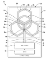
도 1은 본 발명에 따른 안테나 조립체를 포함하는 모바일 통신 디바이스의 도식화된 다이어그램이다.
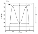
도 2는 본 발명에 따른 프로토타입 안테나 조립체의 측정된 주파수 응답의 그래프이다.
도 3a-3d는 도 1의 안테나 조립체에 관한 방사 패턴 그래프이다.
도 4는 본 발명에 따른 육각형 수동 루프 안테나에 대한 크기와 주파수 사이의 관계를 도시하는 그래프이다.
도 5는 도 1의 안테나 조립체의 회로 등가물의 도식화된 다이어그램이다.
도 6은 본 발명에 따른 안테나 조립체의 또 다른 실시예의 도식화된 다이어그램이다.
도 7은 본 발명에 따른 안테나 조립체의 더 또 다른 실시예의 도식화된 다이어그램이다.
도 8은 본 발명에 따른 안테나 조립체의 체비쉐브(Chebyschev) 실시예에 대한 이득 응답 대 주파수의 그래프이다.
도 9는 본 발명에 따른 안테나 조립체에 대해 측정된 품질 계수의 그래프이다. 1 is a schematic diagram of a mobile communication device including an antenna assembly according to the present invention.
2 is a graph of measured frequency response of a prototype antenna assembly in accordance with the present invention.
3A-3D are graphs of radiation patterns for the antenna assembly of FIG.
4 is a graph showing a relationship between magnitude and frequency for a hexagonal passive loop antenna according to the present invention.
5 is a schematic diagram of circuit equivalents of the antenna assembly of FIG. 1.
6 is a schematic diagram of another embodiment of an antenna assembly according to the present invention.
7 is a schematic diagram of yet another embodiment of an antenna assembly according to the present invention.
8 is a graph of gain response versus frequency for a Chebyschev embodiment of an antenna assembly according to the present invention.
9 is a graph of measured quality factor for an antenna assembly according to the present invention.
본 발명은 이제 본 발명의 바람직한 실시예가 도시되는 첨부된 도면을 참조하여 이하에 더 완전하게 설명될 것이다. 그러나 본 발명은 많은 다른 형태로 구현될 수 있고 여기에 제시된 실시예로 한정되는 것으로 해석되어서는 안 된다. 그보다는, 이들 실시예는 본 개시가 완전해지고 완성되도록 제공되며, 해당 기술 분야의 당업자에게 본 발명의 범위를 완전하게 전달할 것이다. 동일한 번호는 전체에 걸쳐 동일한 부재를 말하고, 프라임 및 멀티플 기호는 대안적인 실시예에서 유사한 부재를 나타내도록 사용된다.The present invention will now be described more fully hereinafter with reference to the accompanying drawings, in which preferred embodiments of the invention are shown. The invention may, however, be embodied in many different forms and should not be construed as limited to the embodiments set forth herein. Rather, these embodiments are provided so that this disclosure will be thorough and complete, and will fully convey the scope of the invention to those skilled in the art. Like numbers refer to like parts throughout, and prime and multiple symbols are used to indicate similar parts in alternative embodiments.
도 1에 대해 최초로 언급하면서, 무선 통신 디바이스(10)는 하우징(11) 및 하우징에 의해 적재되는 무선 통신 회로(12)를 포함한다. 무선 통신 회로(12)는 예를 들어, 셀룰러 통신 회로 또는 무선 측위(radiolocation) 태그 회로일 수 있고, 음성 및/또는 데이터를 전달하도록 구성될 수 있다. 무선 회로(12)는 복수의 주파수 대역, 예를 들어, 셀룰러, WiFi, 및 글로벌 위치확인 시스템(GPS; global positioning system) 대역에 걸쳐 통신하도록 구성될 수 있다. 물론, 무선 통신 회로(12)는 다른 주파수 대역에 걸쳐 통신하도록 구성될 수 있다. 다른 회로, 예를 들어, 제어기(13)는 하우징(11)에 의해 적재되고 무선 통신 회로(12)에 결합될 수 있다. 부가적으로, 무선 통신 디바이스(10)는 제어기(13) 및/또는 무선 통신 회로(12)에 결합되는, 입력 디바이스(미도시), 예를 들어, 입력 키, 및/또는 마이크로폰과 출력 디바이스(미도시), 예를 들어, 디스플레이 및/또는 스피커를 포함할 수 있다. Initially referring to FIG. 1, the
무선 통신 디바이스(10)는 또한 하우징(11)에 의해 적재되고 무선 통신 회로(12)에 결합되는 안테나 조립체(20)를 포함한다. 안테나 조립체(20)는 기판(21)을 설명적으로 포함한다. 기판(21)은 예를 들어, 인쇄 회로 보드 기판일 수 있고, 해당 기술분야의 당업자에 의해 인지될 수 있는 바와 같이, 다른 부품을 적재할 수 있다. 안테나 조립체(20)는 또한 기판(21)에 의해 적재되는 세 개의 동일-크기로된 6각형 형상의 수동 루프 안테나(22a-22c)를 포함한다. 수동 루프 안테나(22a-22c)는 사이드-바이-사이드 관계(나란히)로 배열된다. 도시된 실시예에서, 세 개의 수동 루프 안테나(22a-22c) 각각은 각각의 이웃하는 수동 안테나에 인접한 각각의 직선 측면을 가진다. 바람직한 실시예에서, 예를 들어, 수동 루프 안테나(22a-22c) 각각은 작동 주파수에서 0.5 파장 또는 그보다 작은 원주를 가진다, 예를 들어, 수동 방사 루프 안테나는 자연적으로 공진하거나 전기적으로는 파장에 비해 상대적으로 작다. The
해당 기술분야의 당업자에 의해 인지될 수 있는 바와 같이, 6각형 수동 루프 안테(22a-22c) 각각은 개별적인 안테나 부재로 간주될 수 있고 그래서 결합된 전기적 특성은 루프 안테나 어레이처럼 작동한다. 수동 루프 안테나(22a-22c)의 6각형 형상은 공간의 사용에 증가된 효율성을 유리하게 제공하는 허니컴 격자를 생성한다. 폴리에드라를 채우는 공간의 6각형 타일링은 하우징(21)이 크기에서 상대적으로 한정되는 휴대용 무선 통신 디바이스에서 특히 유리할 수 있다. 수동 루프 안테나의 6각형 형상은 증가된 효율성 이득 및 감소된 전체 크기에 있어서 감소된 전도체 손실에서 증가된 방사 저항을 전개한다.As will be appreciated by those skilled in the art, each of the hexagonal
수동 루프 안테나(22a-22c) 각각은 수동 루프 전도체(27a-27c) 및 그것에 결합된 튜닝 부재(28)를 포함한다. 해당 기술분야의 당업자에 의해 인지될 수 있는 바와 같이, 튜닝 부재(28)는 그것의 크기가 아닌, 특정 수동 루프 안테나(22)의 주파수 대역을 결정한다. 대신에, 각각의 수동 루프 안테나(22)의 크기는 각각의 수동 루프 안테나에 대응하는 주파수 대역에서 안테나 조립체(20)의 이득에 관련된다.Each of the
각각의 수동 루프 안테나(22)는 또한 수동 루프 전도체(27)를 둘러싸는 유전체 절연층(29)을 포함한다. 달리 말해서, 각각의 수동 루프 안테나(22)는 절연된 와이어일 수 있다. 튜닝 부재(28)는 설명적으로 커패시터이고 수동 루프 전도체(27)와 인라인 결합된다. 물론, 튜닝 부재(28)는 부품의 또 다른 유형, 예를 들어, 인덕터일 수 있고, 인라인 결합되지 않을 수 있으며, 예를 들어, 페라이트 비드(ferrite bead)가 수동 루프 전도체(27)와 유전체 절연층(29)을 대신에 둘러쌀 수 있다. 튜닝 부재(28)가 예를 들어, 커패시터일 때, 수동 루프 안테나(22a-22c)는 더 작은 물리적 크기 및/또는 낮은 주파수에서 작동하도록 전기적으로 로드된다. 따라서, 튜닝 부재(28), 또는 커패시터는 크기를 감소시킨다. Each passive loop antenna 22 also includes a dielectric insulating layer 29 surrounding the passive loop conductor 27. In other words, each passive loop antenna 22 may be an insulated wire. The tuning member 28 is illustratively a capacitor and is inline coupled with the passive loop conductor 27. Of course, the tuning member 28 may be another type of component, for example an inductor, and may not be inline coupled, for example, in which ferrite beads are insulated from the passive loop conductor 27 and the dielectric. Layer 29 may instead be enclosed. When the tuning member 28 is, for example, a capacitor, the
해당 기술분야의 당업자에 의해 인지될 수 있는 바와 같이, 능동 루프 안테나(23)는 유도 결합에 의해 수동 루프 안테나(22a-22c)와 협력하고 그래서 수동 루프 안테나는 세 개의 독립적인 튜너블 안테나로서 작동한다. 수동 루프 안테나(22a-22c) 각각의 독립적인 튜닝은 튜닝 부재(28) 각각의 값, 특히, 커패시턴스를 선택하거나 변경하는 것에 의해 달성된다. As will be appreciated by those skilled in the art, the
안테나 조립체(20)는 또한 기판(21)에 의해 적재되는 능동 루프 안테나(23)를 포함한다. 능동 루프 안테나(23)는 원형 형상을 설명적으로 가지며 복수의 수동 루프 안테나(22a-22c) 각각과 부분적으로 같은 공간을 차지한다. 달리 말해서, 능동 루프 안테나(23)와 수동 루프 안테나(22a-22c)의 영역은 서로 터치하지 않고 중첩할 수 있다. 능동 루프 안테나는 능동 루프 전도체(25) 및 그 안에 규정된 한 쌍의 피드포인트(26a, 26b)를 포함한다. 능동 루프 안테나(23)는 또한 능동 루프 전도체(25)를 둘러싸는 절연층(36)을 포함할 수 있다. 달리 말해서, 능동 루프 안테나(23)는 또한 절연된 와이어일 수 있다. 각각의 절연층은 회로를 단락시키지 않도록 수동 루프 안테나(22a-22c)와 능동 루프 안테나(23) 사이에 유전체 간격을 유리하게 제공한다. The
설명적으로, 수동 루프 안테나(22a-22c)의 사이드-바이-사이드 관계는 중심점(24)를 규정하고, 능동 루프 안테나(23)는 설명적으로 중심점과 동심이다. 물론, 능동 루프 안테나(23)는 다른 실시예에서 중심점(24)과 동심이 아닐 수 있다. 해당 기술분야의 당업자에 의해 인지될 수 있는 바와 같이, 오프셋 양의 조절은 수동 루프 안테나(22a-22c) 각각에 결합된 파워의 양에 영향을 미칠 수 있다.Descriptively, the side-by-side relationship of the
피드 전도체(31) 또는 케이블은 안테나 조립체(20)를 피드포인트(26a, 26b)를 통해 무선 통신 회로(12)에 결합시킬 수 있다. 피드 전도체(31)는 예를 들어, 동축 케이블일 수 있고, 피드포인트(26a, 26b) 중 하나에 결합된 중심 전도체(32) 및 피드포인트 중 다른 하나에 결합되고, 유전체층(33)에 의해 내부 전도체로부터 분리되는 외부 전도체(34)를 포함할 수 있다. 예를 들어, 절연된 와이어의 꼬임쌍선과 같은, 케이블 또는 전도체의 다른 유형이 사용될 수 있다. 일부 예에서, 피드 케이블(31)은 그 자체로 안테나가 될 수 있다. 유리하게, 능동 루프 안테나(23)는 의도하지 않게 안테나가 되는 피드 케이블(31)의 효과를 감소시키도록 발룬을 제공할 수 있다. 이것은 수동 루프 안테나(22a-22c)가 피드 케이블(31)에 대해 직류(DC) 연결을 갖지 않기 때문이다(즉, 통전 접촉이 없고, 그보다는 유도 결합이 있다). 능동 루프 안테나(23)는 또한 예를 들어, 동축 피드라인 상의 공통 모드 전류를 감소시키도록 발룬 또는 "절연 변압기(isolation transformer)"로서 기능할 수 있다. The
이제 도 2에 대해 언급하면서, 도 1에 도시된 바와 같은 안테나 조립체(20)와 유사한 다대역 프로토타입 안테나 조립체의 측정된 주파수 응답, 또는 전압 정재파 비에 관한 그래프(50)가 도시된다. 프로토타입 안테나 조립체는 세 개의 6각형 수동 루프 안테나 및 원형 능동 루프 안테나를 포함했다. 제 1 커패시터는 30 피코패럿의 값을 가졌고, 제 2 커패시터는 10 피코패럿이었고, 제 3 커패시터는 20 피코패럿이었다. 따라서, 각각의 수동 루프 안테나 루프는 다른 값의 튜닝 커패시터를 가졌다. 그래프(50)는 각각의 커패시터의 값에 기반해서 독립적으로 구현되는, 약 86 MHz, 106 MHz, 및 144 MHz 각각에서 세 개의 대역(51a, 51b, 51c)을 설명적으로 포함한다. 다대역 프로토타입의 요약은 다음과 같다:Referring now to FIG. 2, a

예를 들어, 개별적인 전기적으로 작은 안테나는 2차 주파수 응답을 가질 수 있다. 따라서, 그러한 안테나는 상대적으로 좁을 수 있는 단일 주파수 대역을 커버할 수 있다. 그러나 안테나 조립체(20)는, 세 개의 주파수 대역 각각이 개별적으로 각각 주파수 대역에 대해 단일 확대된 또는 넓은 주파수 대역을 형성하도록 결합될 수 있도록 튜닝될 수 있다. 더 구체적으로, 각각의 6각형 형상의 수동 루프 안테나(22a-22c)의 공진은 특정 리플에 증가된 대역폭을 제공하도록 체비쉐브 다항식에 따라서 조절될 수 있다. 예를 들어, 수동 루프 안테나 각각은 n차 체비쉐브 다항식의 영으로 스태거 튜닝될 수 있다. 예를 들어, 두 개의 수동 루프 안테나는 2개의 리플 피크를 갖는 4차 체비쉐브 응답 및 단일 수동 루프 안테나의 약 4배의 대역폭을 제공할 수 있다.For example, individual electrically small antennas may have a secondary frequency response. Thus, such an antenna may cover a single frequency band which may be relatively narrow. However, the
더 구체적으로, 예를 들어, 단일 6각형 형상 수동 루프 안테나를 갖는 안테나 조립체는 ax 2 + bx +c=0에 따른 2차 응답을 가진다. 예를 들어, 단일 6각형 형상 수동 루프 안테나가 0.12λ의 직경을 가진다면, 6:1 전압 정재파 비(VSWR) 대역폭은 약 1.52%이다. 예를 들어, 두 개의 6각형 형상 수동 루프 안테나를 갖는, 본 발명에 따른 안테나 조립체는:More specifically, for example, an antenna assembly with a single hexagonal shaped passive loop antenna has a secondary response according to ax 2 + bx + c = 0 . For example, if a single hexagonal shape passive loop antenna has a diameter of 0.12λ, the 6: 1 voltage standing wave ratio (VSWR) bandwidth is about 1.52%. For example, an antenna assembly according to the present invention having two hexagonal shaped passive loop antennas:
![]()
![]()
에 따른 체비쉐브 다항식 응답을 갖고, 여기서:Have a Chebyshev polynomial response according to:
TT nn = n 차의 = nth order 체비쉐브Chevy Chev 다항식 Polynomial
x= 각 주파수 = 2πfx = angular frequency = 2πf
따라서, 각각의 6각형 형상 수동 루프 안테나 역시 0.12λ의 직경을 가진다면, 대역폭은 약 4 x 1.52% 또는 6.1%이다. 체비쉐브 다항식의 리플 주파수는 차수 n과 함께 일반적으로 증가하고 그래서 리플 진폭이 일정하게 유지될 때, 수확체감이 순차 n을 증가시키는 것과 함께 발생한다. 해당 기술분야의 당업자에 의해 인지될 수 있는 바와 같이, 예를 들어, 무한 수의 수동 루프 안테나는 단일 방사 루프 안테나보다 3π까지 더 많은 순시 대역폭을 제공할 수 있다. 테스팅은 두 개의 수동 루프 안테나가 단일 수동 루프 안테나의 4배의 대역폭을 제공한다는 것을 나타낸다. 따라서, 본 발명의 실시예는 감소된 크기 및 증가된 순시 대역폭에 있어서 다목적 튜닝을 갖는 루프 안테나 어레이를 유리하게 제공한다. 본 발명의 실시예는 인덕터 및/또는 커패시터의 래더 네트워크 없이, 예를 들어, 수동 부품의 외부 집중 부재 네트워크보다는 방사 구조를 통한 다목적 튜닝을 유리하게 제공한다. 이제 도 3a-3d, 및 도 4의 그래프(61, 62, 63, 64, 65)에 대해 언급하면서, 안테나 조립체(20)의 방사 패턴은 일반적으로 토로이달이다. 그래프(61)는 직교 좌표계에서 안테나 조립체(20)의 평면을 도시한다. 해당 기술분야의 당업자에 의해 인지될 수 있는 바와 같이, 안테나 조립체(20)의 평면은 XY 평면에 놓인다. 그래프(62)는 안테나 조립체(20)의 XY 평면 방사 패턴 컷이 원형이고 전방향임을 도시한다.Thus, if each hexagonal shape passive loop antenna also has a diameter of 0.12 lambda, the bandwidth is about 4 x 1.52% or 6.1%. The ripple frequency of the Chebyshev polynomial generally increases with order n and so when the ripple amplitude remains constant, the diminishing returns occur with increasing order n. As will be appreciated by those skilled in the art, for example, an infinite number of passive loop antennas may provide up to 3 [pi] instantaneous bandwidth than a single radiating loop antenna. Testing shows that two passive loop antennas provide four times the bandwidth of a single passive loop antenna. Accordingly, embodiments of the present invention advantageously provide a loop antenna array with versatile tuning in reduced size and increased instantaneous bandwidth. Embodiments of the present invention advantageously provide multi-purpose tuning through a radiating structure without a ladder network of inductors and / or capacitors, for example rather than an external concentrating member network of passive components. Referring now to FIGS. 3A-3D and the
유사하게, 그래프(63, 64) 각각은 YZ과 ZX 평면에서 방사 패턴 컷의 형상이 함수 cos2θ를 갖는 두 개의 꽃잎을 가진 장미의 형상임을 도시한다. 방사 패턴은 더 작은 루프 크기에서 균일한 루프 주위의 전류 분포의 푸리에 변환이다. ½ 파 다이폴이 수직으로 편파되고 안테나 조립체(20)가 수평으로 편파됨에도, 안테나 조립체(20) 방사 패턴 형상은 그래프(61) Z축을 따라 지향된 정준 ½ 파 와이어 다이폴과 유사하다. 수평 편파는 예를 들어, 대류권 반사에 의한 장 범위 전파에서 돕기에 특히 유리할 수 있다. 게다가, 안테나 조립체(20)는 안테나 평면 옆으로 방사 패턴 널을 갖고, 방사 패턴 로브는 안테나 평면에 있다. YZ 및 ZX 패턴 컷에서 안테나 조립체(20)의 반전력 빔폭은 약 82도이다. 지향성은 1.5이다. 해당 기술분야의 당업자에 의해 인지될 수 있는 바와 같이, 예를 들어, 미스매치 손실이 영일 때, 구현된 이득 및 방사 패턴은:Similarly, the
구현된 이득 = 10 Implemented Gain = 10 loglog 1010 (η D (η D coscos 22 θ)θ)
에 따라서 계산될 수 있고, 여기서:Can be calculated according to where:
η = 안테나 조립체(20)의 방사 효율성η = radiation efficiency of the
D = 안테나 지향성 = 안테나 조립체(20)에 있어서 1.5D = antenna directivity = 1.5 for
Θ = 안테나 조립체의 평면에 대한 Θ = plane of antenna assembly 법선으로부터From the normal 측정된 앙각 Measured elevation
20.(안테나 평면에 대한 법선 θ=020. (Normal θ = 0 to antenna plane 00 및 안테나 조립체 평면에서 θ=90 And θ = 90 in the antenna assembly plane 00 ))
실제에서, 상대적으로 낮은 손실 튜닝 커패시터와 함께, 방사 효율성 η는 대개 수동 루프 안테나 전도체 손실 저항 Rl과 관련한 수동 루프 안테나(22a-22c) 방사 저항 Rr의 함수이고 그래서 방사 효율성은:In practice, with a relatively low loss tuning capacitor, the radiation efficiency η is usually a function of the passive loop antenna (22a-22c) radiation resistance R r with respect to the passive loop antenna conductor loss resistance R l and so the radiation efficiency is:
방사 효율성 η = Radiation efficiency η = RR RR /(/ ( RR rr ++ RR ll ))
로서 계산될 수 있고 구현된 이득은:And the gain implemented is:
구현된 이득 = 1.76-10 logImplemented Gain = 1.76-10 log 1010 (( RR rr /(/ ( RR rr ++ RR ll )) dBildBil
로서 계산될 수 있다.Lt; / RTI >
도 4의 그래프(65)는 단일 6각형 수동 루프 안테나에 있어서 크기, 구현된 이득, 및 주파수 사이의 일반적인 관계(계산됨)를 도시한다. 도 4의 그래프(65)는 또한 안테나 조립체의 실시예에 의해 제공된 일반적인 구현된 이득을 도시한다. 그래프(65)에 대응하는 안테나 조립체는 도 1의 안테나 조립체(20)와 유사한 단일 수동 루프 안테나이고, 구리이며 3 RF 표면 깊이 두께보다 더 크다. 안테나 조립체는 예를 들어, 방사 패턴 피크 이득을 사용하는 것에 의해, 튜닝되고 매치되며, 편파는 동일-편파된다. 튜닝 부재는 품질 계수 Q=1000을 갖는 커패시터이고, 수동 루프 안테나 선폭은 수동 루프 안테나 외부 직경에서 약 0.15이다. 설명적으로, 선(66, 67, 68, 및 69)은 각각, 구현된 이득 +1.5, 0.0, -10.0, 및 -20.0 dBil에 대응한다. 해당 기술분야의 당업자에 의해 인지될 수 있는 바와 같이, 본 실시예는 안테나 크기와 구현된 이득 사이의 트레이드오프를 유리하게 허용하고 크기에 대해 증가된 효율성을 제공한다.The
도 1의 안테나 조립체(20)와 유사한 프로토타입 안테나 조립체의 테스트에서, 안테나 조립체는 글로벌 위치확인 시스템 (GPS) 위성을 사용하는 무선 측위 목적을 위해 사용되었다. 안테나 조립체는 상대적으로 높은 GPS 위성군의 능력을 제공했고 그래서 많은 위성이 즉시 수신될 수 있었다. 프로토타입 안테나 조립체 GPS 수신에 관한 성능 요약은 다음과 같다:In testing of a prototype antenna assembly similar to the

GPS 프로토타입은 감소된 딥 크로스 감지 원형 편파 페이드의 작동 이점을 가졌다. 오른쪽 원형으로 편파된 마이크로스트립 패치 안테나는 반전될 때, 왼쪽 원형으로 편파되는 경향이 있어서, GPS 수신에서 딥 페이드를 생성할 수 있다. 따라서, 무선 통신 회로가 안테나 조립체와 함께, 예를 들어, GPS 무선 측위 태그를 포함할 때, 안테나 조립체는 예를 들어, 원형 편파를 갖는 마이크로스트립 패치 안테나보다 증가된 신뢰도의 수신 및 더 높은 이득을 제공했다. GPS 무선 측위 디바이스에서, 안테나는 일반적으로 조준되지 않고 지향되지 않는다. 실제로, 본 발명의 실시예에서, 수동 루프 안테나의 원주가 ½ 파장에 접근할 때, 방사 패턴은 거의 구형이 되고 등방성이 된다. The GPS prototype had the operational advantage of reduced deep cross sensing circular polarization fade. Microstrip patch antennas polarized in the right circle tend to be polarized in the left circle when inverted, thus creating a deep fade in GPS reception. Thus, when the wireless communication circuitry includes, for example, a GPS radio location tag with the antenna assembly, the antenna assembly can receive increased reliability and higher gain than, for example, a microstrip patch antenna with circular polarization. Provided. In a GPS radiolocation device, the antenna is generally not aimed and not directed. Indeed, in an embodiment of the invention, when the circumference of the passive loop antenna approaches ½ wavelength, the radiation pattern becomes nearly spherical and isotropic.
이제 도 5에 대해 추가적으로 언급하면서, 안테나 조립체(20)의 회로 등가 모델은 다중 2차 권선을 갖는 변압기로서 간주될 수 있고, 그래서 예를 들어, 전력 분배기가 구현된다. 신호 발생기 S는 무선 통신 회로(12)에 대응한다. 해당 기술분야의 당업자에 의해 인지될 수 있는 바와 같이, 능동 루프 안테나(23)는 1차 권선 L에 대응하는 반면에, 세 개의 6각형 수동 루프 안테나(22a-22c)는 각각의 2차 k1, k2, k3에 대응한다. 전력은 세 개의 6각형 수동 루프 안테나(22a-22c)에 의해 규정된 중심점(24)과 동심인 능동 루프 안테나(23)에 의해, 세 개의 방향으로 동일하게 분배될 수 있다. 능동 루프 안테나(23)에 걸쳐 세 개의 6각형 수동 루프 안테나(22a-22c)의 같은 공간을 차지하는 양의 조절은 다중 턴 권선을 갖는 통상의 변압기의 "턴 비율(turns ratio)"의 조절과 등가이다. Referring further to FIG. 5, the circuit equivalent model of the
도시된 대응하는 회로 도식화된 다이어그램에서, 등가 튜닝 부재는 커패시터 C1, C2, C3이다. 도시된 레지스터 Rr1, Rr2, Rr3는 방사 저항에 대응한다. 달리 말해서, 이것은 전도체 그 자체, 예를 들어, 구리 전도체에 의해 제공되는 저항이다. R11, R12, R13은 줄 효과 가열로부터의 전도체 저항 손실에 대응한다. 해당 기술분야의 당업자에 의해 인지될 수 있는 바와 같이, 안테나 조립체(20)가 너무 작다면, R1은 증가하고, 성능은 잠재적으로 허용할 수 없는 수준으로 감소할 수 있다. R1은 일반적으로 안테나 효율성의 지배적인 결정요인이다. 사실, 튜닝 커패시터 등가 직렬 저항(ESR) 손실은 종종 무시될 수 있다. 그러므로 개별적인 수동 루프 안테나의 방사 효율성 η은: In the corresponding circuit schematic diagram shown, the equivalent tuning members are capacitors C 1 , C 2 , C 3 . The illustrated resistors R r1 , R r2 , R r3 correspond to radiation resistance. In other words, this is the resistance provided by the conductor itself, for example a copper conductor. R 11 , R 12 and R 13 correspond to conductor resistance losses from Joule effect heating. As will be appreciated by those skilled in the art, if
![]()
![]()
에 의해 대략적으로 있을 수 있고 구현된 이득은:It can be approximately by and the benefits implemented are:
![]()
![]()
에 의해 대략화될 수 있다.Can be approximated by
배경에서와 같이, 금속 전도체의 손실 저항은 일반적으로 실온의 전기적으로 작은 안테나의 효율성 및 이득에 대한 근본적인 제한이다. 전기적으로 작을 때, 개별적인 수동 루프 안테나의 지향성은 1.76 dB이다. 이러한 지향성의 값은 수동 루프 안테나의 수와 함께 현저하게 증가하거나 감소하지 않는다. 전형적인 실제에서, 능동 루프 안테나는 50 옴의 저항을 제공하도록 조절될 수 있고, 능동 루프의 금속 전도체 손실은 무시될 수 있다. As in the background, the loss resistance of metal conductors is a fundamental limitation on the efficiency and gain of electrically small antennas, typically at room temperature. When electrically small, the directivity of the individual passive loop antenna is 1.76 dB. The value of this directivity does not increase or decrease significantly with the number of passive loop antennas. In a typical practice, the active loop antenna can be adjusted to provide 50 ohms of resistance, and the metal conductor losses of the active loop can be neglected.
수동 루프 안테나는 루프 구조가 중첩하지 않을 때, 일반적으로 서로 현저하게 결합하지 않는다(예를 들어, 상호 결합은 이러한 환경에서 약 -15 dB보다 작다). 수동 루프 안테나의 중첩은 원하는 대로 상호 결합을 변경할 수 있다. 상호 결합의 차수는 체비쉐브 응답 사이의 간격을 조절한다. 따라서, 본 발명의 특징은 구동 저항(능동 루프 직경), 리액턴스(튜닝 커패시터), 주파수(튜닝 부재 값), 부재 상호 결합(수동 루프 안테나 사이의 간격), 크기(튜닝 부재는 로딩을 제공한다), 이득(수동 루프 안테나 직경), 및 대역폭(수동 루프 안테나(22)의 수는 주파수 응답 리플을 조절한다)의 제어를 허용한다. Passive loop antennas generally do not significantly join each other when the loop structures do not overlap (eg, mutual coupling is less than about -15 dB in this environment). The superposition of the passive loop antennas can change the mutual coupling as desired. The order of mutual coupling controls the spacing between Chebyshev responses. Thus, features of the present invention include drive resistance (active loop diameter), reactance (tuning capacitor), frequency (tuning member value), member mutual coupling (gap between passive loop antennas), size (tuning member provides loading). , Gain (passive loop antenna diameter), and bandwidth (the number of passive loop antennas 22 adjusts the frequency response ripple).
이제 도 6에 대해 언급하면서, 안테나 조립체(20')의 또 다른 실시예는 각각이 사각형 형상을 갖고 기판(21')의 제 1 측면(37')에 의해 적재되는 네 개의 수동 루프 안테나(22a'-22d')를 설명적으로 포함한다. 네 개의 수동 루프 안테나(22a'-22d')는 사이드-바이-사이드 관계로 설명적으로 배열되고 사각형 수동 루프 안테나 각각의 모서리에 대응하는 중심점(24')을 규정한다. 기판(21')의 제 2 측면(38') 또는 수동 루프 안테나(22')로부터의 반대편 측면 상에 적재되는, 능동 루프 안테나(23')는 네 개의 사각형 형상 수동 루프 안테나(22a'-22d') 각각과 부분적으로 같은 공간을 차지한다. 네 개의 사각형 수동 루프 안테나(22a'-22d') 각각은 각각의 튜닝 부재(28a'-28d'), 또는 각 수동 루프 전도체(27a'-27d')에 결합된 커패시터를 포함한다. 해당 기술분야의 당업자에 의해 인지될 수 있는 바와 같이, 네 개의 수동 루프 안테나(22a'-22d') 각각은 각각의 커패시터(28a'-28d')에 의해 결정된 주파수 대역에 대응한다. Referring now to FIG. 6, another embodiment of the
이제 도 7에 대해 언급하면서, 안테나 조립체(20”)의 더 또 다른 실시예는 각각이 삼각형 또는 파이 형상을 갖는 여덟 개의 수동 루프 안테나(22a”-22h”)를 설명적으로 포함한다. 여덟 개의 수동 루프 안테나(22a”-22h”)는 사이드-바이-사이드 관계로 설명적으로 배열되고 삼각형 수동 루프 안테나 각각의 포인트에 대응하는 중심점(24”)을 규정한다. 능동 루프 안테나(23”)는 여덟 개의 삼각형 형상 수동 루프 안테나(22a”-22h”) 각각과 부분적으로 같은 공간을 차지한다. 여덟 개의 삼각형 수동 루프 안테나(22a”-22”) 각각은 각각의 수동 루프 전도체(27a”-27h")에 결합된, 각각의 튜닝 부재(28a'-28d'), 또는 커패시터를 포함한다. 해당 기술분야의 당업자에 의해 인지될 수 있는 바와 같이, 여덟 개의 수동 루프 안테나(27a”-27h”) 각각은 각각의 커패시터(28a”-28h”)에 의해 결정된 주파수 대역에 대응한다.Referring now to FIG. 7, yet another embodiment of the
여기에 설명된 각각의 수동 루프 안테나(22)는 설명적으로 동일한 크기 형상이고, 수동 루프 안테나는 임의의 다각형 형상을 가질 수 있다. 부가적으로, 일부 실시예에서, 수동 루프 안테나(22) 각각은 동일한 크기가 아닐 수 있다.Each passive loop antenna 22 described herein is descriptively the same size shape, and the passive loop antenna may have any polygonal shape. Additionally, in some embodiments, each of the passive loop antennas 22 may not be the same size.
방법적 측면은 하우징(11)에 의해 적재되고 무선 통신 회로(12)에 결합되는 안테나 조립체(20)를 구성하는 방법에 관한 것이다. 방법은 사이드-바이-사이드 관계로 기판(21)에 의해 적재되도록 복수의 수동 루프 안테나(22)를 위치시키는 단계를 포함한다. 수동 루프 안테나(22) 각각은 수동 루프 전도체(27)와 그것에 결합된 튜닝 부재(28)를 포함한다. 방법은 또한 기판(21)에 의해 적재되도록 그리고 수동 루프 안테나(22) 각각과 적어도 부분적으로 같은 공간을 차지하도록 능동 루프 안테나(23)를 위치시키는 단계를 포함한다. 능동 루프 안테나(23)는 능동 루프 전도체(25) 및 그 안에 규정된 한 쌍의 피드포인트(26a, 26b)를 포함한다.The method aspect relates to a method of constructing an
이제 도 8의 그래프(100)에 대해 언급하면서, 안테나 조립체의 더블 튜닝된/4차 체비쉐브 실시예의 이득 응답이 도시된다. 설명적으로, 두 개의 이득 피크를 갖는 리플된 통과대역(106)이 있지만, 통과 대역의 두 개의 피크는 예를 들어, 단일 계속 통과대역인 것으로 간주되고, 그래서 리플을 갖는 단일 대역 안테나가 형성된다. 통과대역(106)의 리플은 예를 들어, 증가된 대역폭을 제공하기에 특히 유리할 수 있다. 그래프(100)에 대응하는 안테나 조립체는 서로 인접한 두 개(2)의 수동 루프 안테나와 각각의 수동 루프 안테나와 중첩하는 하나(1)의 능동 루프 안테나를 포함한다. 더블 튜닝된 4차 체비쉐브 다항식 응답을 구현하기 위해, 방사 루프 안테나는 우선적으로 동일한 크기의 것이고, 그들은 유사하거나 동일한 값의 튜닝 부재 커패시터를 사용한다. 따라서, 수동 루프 안테나의 개별적인 공진 주파수는 그 자체로 동일하다. 그러나, 수동 루프 안테나가 서로 상대적으로 가까워질 때, 상호 결합은 주파수 응답에서 두 개의 이득 피크(106, 108)를 형성하게 할 수 있다. 따라서 두 개의 개별적인 수동 루프 안테나의 2차 응답은 더블 튜닝된 4차 체비쉐브 응답이 되도록 결합한다.Referring now to the
리플 진폭(104) 및 대역폭(106)은 서로에 대해 수동 루프 안테나의 간격을 조절하는 것에 의해 조절될 수 있다. 두 개의 수동 루프 안테나가 더 떨어질 때, 이득 피크(102) 사이의 간격은 감소되고 그래서 대역폭(106)이 감소되며, 리플 레벨 진폭(104)이 감소된다.
두 개의 수동 루프 안테나 사이의 간격이 더 가까워질 때, 이득 피크(108, 110) 사이의 간격(102)이 증가되고(응답이 벌어지고), 그래서 대역폭(106)이 증가되며, 리플 진폭(104)이 증가된다. 두 개의 수동 루프 안테나는 상대적으로 매우 큰 대역폭을 생성하도록 심지어 서로 중첩할 수 있다(그러나 서로 터치하지 않는다). 인지될 수 있는 바와 같이, 더블 튜닝된 4차 체비쉐브 실시예는 리플 레벨(104)과 대역폭(106) 사이의 넓고 계속적인 범위의 트레이드오프를 유리하게 제공한다. As the spacing between the two passive loop antennas gets closer, the spacing 102 between the gain peaks 108, 110 increases (responses open), so the
두 개의 수동 루프 안테나를 사용하는 더블 튜닝된 4차 체비쉐브 실시예에서, 능동 루프 안테나의 직경은 안테나가 무선 통신 회로에 제공하는 회로 저항을 조절한다. 더 큰 직경 능동 루프는 송신기에 제공되는 저항을 증가시키고, 더 작은 직경 능동 루프는 송신기에 제공되는 저항을 감소시킨다. 50 옴 저항은, 능동 루프의 직경이 약 0.2 내지 0.5 수동 루프 안테나의 직경이었을 때, 실제로 용이하게 획득가능했다. 능동 루프 안테나의 크기는 능동 및 1 대 1 VSWR을 얻도록 조절될 수 있다. 대안적으로, 능동 루프 안테나는 두 개의 이득 피크(108, 110)에서 증가된 VSWR을 갖는 증가된 대역폭에 대해 과능동 트레이드를 제공하도록 크기에서 증가될 수 있다.In a double tuned quaternary Chebyshev embodiment using two passive loop antennas, the diameter of the active loop antenna adjusts the circuit resistance that the antenna provides to the wireless communication circuitry. Larger diameter active loops increase the resistance provided to the transmitter and smaller diameter active loops reduce the resistance provided to the transmitter. The 50 Ohm resistance was actually readily obtainable when the diameter of the active loop was about 0.2 to 0.5 passive loop antenna. The size of the active loop antenna can be adjusted to obtain active and one-to-one VSWR. Alternatively, the active loop antenna can be increased in size to provide overactive trade for increased bandwidth with increased VSWR at two
능동 루프 안테나는 주어진 주파수에 걸쳐 저항 보상을 유리하게 제공한다. 달리 말해서, 수동 루프 안테나가 더 작아짐에 따라, 그들의 방사 저항은 강하하지만, 수동 루프 안테나가 더 작아짐에 따라서 능동 루프 안테나의 결합 인자는 증가한다. 따라서, 전자기기 회로에 의해 보이는 원하는 저항은 상대적으로 넓은 대역폭에 걸쳐 일정할 수 있다. 보상 거동은 감소된 수동 루프 안테나 원주로 균일화하도록 사인곡선으로부터의 수동 루프 안테나의 전류 분포에서의 트랜지션으로 인한 것으로 생각된다. 루프 안테나는 전기적으로 작을 때 더 강한 자기의 근거리 장을 갖고 그래서 그들은 더 양호한 변압기 부속물이 된다. 수동 루프 안테나는 방사를 위한 원거리 장 안테나이고, 또한 근거리 장 안테나이다.Active loop antennas advantageously provide resistance compensation over a given frequency. In other words, as passive loop antennas become smaller, their radiated resistance drops, but as the passive loop antenna becomes smaller, the coupling factor of the active loop antenna increases. Thus, the desired resistance seen by the electronics circuit can be constant over a relatively wide bandwidth. The compensation behavior is believed to be due to the transition in the current distribution of the passive loop antenna from the sinusoid to equalize the reduced passive loop antenna circumference. Loop antennas have a near field of stronger magnetism when they are electrically small so they become better transformer attachments. Passive loop antennas are far field antennas for radiation, and are also near field antennas.
가장 높은 이득은 수동 루프 안테나를 형성하는 전도체가 루프 외부 직경의 0.15에 가까운 폭을 가질 때 일어난다. 따라서, 수동 루프 안테나가 1.0 인치의 외부 직경을 갖고, 각각의 수동 루프 안테나가 와이어라면, 와이어 직경이 0.15 인치일 때 가장 높은 구현된 이득이 일반적으로 발생한다. 수동 루프 안테나가 직경에서 1인치이고 인쇄 배선 기판(PWB) 선으로서 형성된다면, 선폭 역시 증가된 방사 효율성을 위해 약 0.15 인치이어야만 한다. 물론 원한다면 다른 전도체 폭이 사용될 수 있다. The highest gain occurs when the conductors forming the passive loop antenna have a width close to 0.15 of the loop outer diameter. Thus, if the passive loop antenna has an outer diameter of 1.0 inch and each passive loop antenna is a wire, the highest realized gain generally occurs when the wire diameter is 0.15 inch. If the passive loop antenna is one inch in diameter and formed as a printed wiring board (PWB) line, the line width should also be about 0.15 inch for increased radiation efficiency. Of course, other conductor widths may be used if desired.
전도체 손실 저항은 선폭이 너무 작을 때 효율적으로 전도하기에는 지나치게 적은 금속이 있기 때문에 증가된다. 그렇지만, 선폭이 지나치게 클 때, 근접 효과가 전도체 손실 저항을 증가시킨다. 전도체 근접 효과가 발생할 때, 전류는 루프 전도체의 내부 에지를 따라 흐르지만 모든 금속이 방사를 위해 사용되는 것은 아니다. 루프의 반대편 측면 상의 루프 전도체는 근접 효과를 일으킨다. 루프의 홀은 일반적으로 적절하게 크기조절되어야만 한다. 수동 루프 안테나를 위한 최적 루프 전도체 선폭은 실험에 의해 검증되었다.Conductor loss resistance is increased because there are too few metals to conduct efficiently when the line width is too small. However, when the line width is too large, the proximity effect increases the conductor loss resistance. When the conductor proximity effect occurs, current flows along the inner edge of the loop conductor but not all metal is used for radiation. Loop conductors on opposite sides of the loop cause a proximity effect. Holes in the loop should generally be sized properly. The optimal loop conductor line width for the passive loop antenna was verified experimentally.
도 9의 그래프(110)는 PWB 실시예 단일 수동 루프 안테나 대 루프 전도체 선폭의 측정된 품질 계수(Q)(111)를 도시한다. Q는 안테나 이득의 인디케이션이고 그래서 Q가 가장 높을 때 구현된 안테나 이득이 가장 높다. 외부 루프 직경은 1.0 인치였고 그것은 146.52 MHz에서 작동되었고 그래서 외부 루프 직경은 λ/84였다. 따라서, 146.52 MHz에서의 임계 능동 및 공진이 고려되고 조절되었다. PWB 구리선의 두께는 3 표면 깊이 두께보다 더 컸다. 루프 안테나 홀이 외부 직경의 90 퍼센트였을 때, 22 피코패럿 커패시터가 146.52 MHz에서 공진을 설정하도록 루프의 갭을 가로질러 연결되었다. 수동 루프 안테나 내부 홀 크기가 영이었을 때, 안테나는 효과적으로 노치된 금속 디스크였다. 그것은 디스크 림에서 노치를 가로질러 290 피코패럿 칩 커패시터를 사용했고, 공진은 다시 146.52 MHz에 있었다. 도 9의 그래프(110)로부터 도시된 바와 같이 가장 양호한 측정된 Q(111)는 225였고, 이것은 내부 홀의 직경이 루프 외부 직경의 70%이었을 때 발생했다. 루프 외부 직경은 1.0 인치였고, 루프 내부 직경은 가장 높은 Q 및 구현된 이득에서 0.7 인치로 동일했다. 그러므로 가장 양호한 구현된 이득을 위한 선폭은 (1.0-0.7)/2=0.15 루프 외부 직경이었다.
능동 루프 안테나(23)는 일반적으로 눈에 띄게 방사하지 않거나 현저한 옴 손실을 갖지 않았다. 배경으로서, 능동 루프 안테나(23)는 또한 절연 변압기 유형의 발룬을 제공한다.
테스팅은 안테나 조립체(20)의 G10 및 FR4 유형 에폭시 글래스 인쇄 회로 기판 실시예에서의 손실이 UHF에서, 예를 들어, 300 MHz와 3000 MHz 사이의 주파수에서 미미하다는 것을 나타냈다. 따라서, 대개의 상업적 회로 소재는 일반적으로 기판(21)에 적합하다. 안테나 조립체(20)는 PWB 유전체 손실을 최소화하는 방사 전기 근거리 장보다는 더 강한 방사 자기 근거리 장을 갖는 것에 의해 이러한 작동 이점을 달성한다. 부가적으로, 안테나 조립체(20) 튜닝 및 로딩은 PWB 유전체보다는 부품 커패시터에 의해 달성된다. 예를 들어, 칩 커패시터는 상대적으로 저렴하고 저 손실이며, NPO 다양성은 상대적으로 평평한 온도 계수를 가진다. 온도에 걸친 안정적인 커패시턴스는 안테나 조립체(20)가 온도에 걸쳐 작동의 상대적으로 안정적인 주파수를 가질 수 있다는 것을 의미한다. 이것은 예를 들어, 일반적인 마이크로스트립 패치 안테나에 대한 안테나 조립체(20)의 이점일 수 있다. Testing has shown that the losses in the G10 and FR4 type epoxy glass printed circuit board embodiments of the
배경으로서, 마이크로스트립 패치 안테나는 안테나 "패치"가 PWB 유전체에서 전기 근거리 장에 집중하는 인쇄 회로 송신 라인을 형성하기 때문에 값비싸고, 저손실 제어된 유전율 소재를 요구할 수 있다. 마이크로스트립 패치 안테나 PWB 소재의 커패시턴스는 일반적으로 온도에 대해 NPO 칩 커패시터만큼 안정적이지 않다. 따라서 안테나(20)는 안정적인 튜닝을 가질 수 있고 평면일 수 있고 상대적으로 저비용으로 구성하기에 상대적으로 용이할 수 있다.As a background, microstrip patch antennas may require expensive, low loss controlled dielectric constant materials because antenna “patches” form printed circuit transmission lines that focus on electrical near fields in the PWB dielectric. The capacitance of microstrip patch antenna PWB materials is typically not as stable as temperature NPO chip capacitors. Thus,
본 발명의 실시예는 다대역 작동을 유리하게 제공하고 및/또는 체비쉐브 통과대역 응답을 갖는 상대적으로 넓은 단일 대역 대역폭을 제공한다. 그러나, 안테나 조립체의 실시예는 또한 넓은 튜닝가능한 대역폭을 제공한다. 넓은 범위에 걸친 가변적인 튜닝이 예를 들어, 튜닝 부재(28)의 리액턴스를 변경하는 것에 의해 달성된다. 따라서, 튜닝 부재(28)는 예를 들어, 가변 커패시터일 수 있다. 튜닝가능한 대역폭은 상대적으로 낮은 전압 정재파 비(VSWR)를 갖는 7 대 1 주파수 범위에 걸쳐 있을 수 있다. HF 프로토타입에서, 2 대 1 아래 VSWR이 10 내지 1000 피코패럿의 범위를 갖는 진공 가변 커패시터를 사용하여 계속적인 3 내지 22 MHz 튜닝 범위에 걸쳐 구현되고, 수동 루프 안테나(22)는 18 피트의 원주를 갖는 구리 배수관의 6각형으로부터 형성되었다. 안테나 작동 주파수의 변화는 튜닝 부재(28)에서 리액턴스 변화의 제곱근이고, 그래서, 예를 들어, 작동 주파수를 두 배로 하기 위해, 튜닝 부재 커패시터 값은 원래 값의 1/22=1/4로 감소된다. 튜닝 부재(28)는 예를 들어, 전자 튜닝을 위한 버랙터 다이오드일 수 있다. 일단 수동 루프 안테나(22)의 인덕턴스가 알려지면, 튜닝 부재(28)의 원하는 값이 공통 공진 식 1/2π√LC로부터 계산될 수 있다. 수동 루프 안테나(22)의 인덕턴스는 식:Embodiments of the present invention advantageously provide multiband operation and / or provide a relatively wide single band bandwidth with Chebyshev passband response. However, embodiments of the antenna assembly also provide a wide tunable bandwidth. Variable tuning over a wide range is achieved, for example, by changing the reactance of the tuning member 28. Thus, tuning member 28 may be, for example, a variable capacitor. The tunable bandwidth can span a 7 to 1 frequency range with a relatively low voltage standing wave ratio (VSWR). In the HF prototype, VSWR below 2 to 1 is implemented over a continuous 3 to 22 MHz tuning range using a vacuum variable capacitor with a range of 10 to 1000 picofarads, and the passive loop antenna 22 is 18 feet of circumference. It was formed from the hexagon of a copper drain pipe with The change in antenna operating frequency is the square root of the reactance change in the tuning member 28, so that, for example, to double the operating frequency, the tuning member capacitor value is reduced to 1/2 2 = 1/4 of the original value. do. Tuning member 28 may be, for example, a varactor diode for electronic tuning. Once the inductance of the passive loop antenna 22 is known, the desired value of the tuning member 28 can be calculated from the
L 마이크로-헨리=0.01595[2.303 LogL micro-henry = 0.01595 [2.303 Log 1010 (8D/d-2)](8D / d-2)]
을 사용하여 측정되거나 계산될 수 있고, 여기서:Can be measured or calculated using:
D = 수동 루프 안테나의 평균 D = average of passive loop antenna 직경diameter
d = d = 와이어wire 전도체의 Conductor 직경diameter
튜닝 부재(28)의 커패시턴스를 증가시키는 것은 안테나 조립체(20)의 작동 주파수를 낮추고, 커패시턴스를 감소시키는 것은 주파수를 상승시킨다. 원한다면 인덕터가 사용될 수 있음에도, 대개의 환경에서, 감소된 손실을 위한 튜닝 부재(28)로서 커패시터를 사용하는 것이 바람직하다. 안테나 조립체(20)에 관한 실시예와 어플리케이션은 확장된 범위를 갖는 텔레비전 및 FM 방송 수신을 위한 것이다. 이들 주파수 대역에서의 일반적인 방송은 수평 편파 부품을 포함하고, 안테나 조립체(20)는 수평 평면에서 지향될 때 수평 편파 부품에 유리하게 응답한다. 수평 편파는 대류권 굴절에 의해 수평선 위로 전파하는 것으로 알려져 있다. 따라서, 안테나 조립체(20)는 수직 ½ 파 다이폴보다 더 큰 범위를 제공할 수 있다. 안테나 조립체(20)는 수평으로 편파될 때 전방향이고, 조준은 요구되지 않을 수 있다. 수동 루프 안테나(22a-22c)는 직경이 19인치일 때 100 MHz에서 +1.0 dBil 구현된 이득을 제공할 수 있고, 따라서 실내에서 사용될 수 있다.Increasing the capacitance of the tuning member 28 lowers the operating frequency of the
루프 안테나와 다이폴 안테나 사이에 많은 차이가 있을 수 있음에도, 전기적으로 작은 다이폴 안테나 및 루프 안테나는 각각 커패시터와 인덕터와 함께 더 작은 크기로 일반적으로 로드된다. 현재 기술수준에서, 그리고 실온에서, 전도체보다 더 양호한 절연체가 있고, 그래서 커패시터의 효율성 및 Q가 일반적으로 인덕터보다 훨씬 더 양호하다. 실제로, 커패시터의 품질 계수는 일반적으로 인덕터보다 10 내지 100배 더 양호하다. 따라서, 본 발명의 안테나 조립체의 실시예와 유사한 루프 안테나는 상대적으로 낮은 손실 및 상대적으로 저렴한 커패시터를 사용하여 크기 감소, 로딩, 및 튜닝을 달성할 수 있기 때문에 다이폴 안테나보다 바람직할 수 있다. 루프 안테나는 또한 한정된 또는 감소된 추가적인 부품으로 인덕터 및 변압기 권선을 제공한다. 따라서, 본 발명의 실시예는 안테나 인덕터, 매칭 변압기, 및 발룬이 안테나 구조에 일체화되는 복합 설계를 제공한다. Although there can be many differences between loop antennas and dipole antennas, electrically small dipole antennas and loop antennas are generally loaded in smaller sizes with capacitors and inductors respectively. At the current state of the art, and at room temperature, there is an insulator that is better than the conductor, so the efficiency and Q of the capacitor is generally much better than the inductor. In practice, the quality factor of the capacitor is generally 10 to 100 times better than the inductor. Thus, loop antennas similar to embodiments of the antenna assembly of the present invention may be preferred over dipole antennas because they can achieve size reduction, loading, and tuning using relatively low loss and relatively inexpensive capacitors. The loop antenna also provides inductor and transformer windings with limited or reduced additional components. Accordingly, embodiments of the present invention provide a composite design in which the antenna inductor, matching transformer, and balun are integrated into the antenna structure.
Claims (10)
상기 하우징에 의해 적재되는 무선 통신 회로; 및
상기 하우징에 의해 적재되고 상기 무선 통신 회로에 결합되며,
기판,
복수의 수동 루프 안테나 각각이 수동 루프 전도체 및 그것에 결합된 튜닝 부재를 포함하고, 상기 기판에 의해 적재되고 사이드-바이-사이드 관계로 배열되는 상기 복수의 수동 루프 안테나, 및
능동 루프 안테나가 능동 루프 전도체 및 그 안에 규정된 한 쌍의 피드포인트를 포함하고, 상기 기판에 의해 적재되고 상기 복수의 수동 루프 안테나 각각과 적어도 부분적으로 같은 공간을 차지하도록 배열된 상기 능동 루프 안테나를 포함하는 안테나 조립체;를 포함하는 것을 특징으로 하는 무선 통신 디바이스.housing;
Wireless communication circuitry loaded by the housing; And
Loaded by the housing and coupled to the wireless communication circuit,
Board,
The plurality of passive loop antennas each comprising a passive loop conductor and a tuning member coupled thereto, the plurality of passive loop antennas loaded by the substrate and arranged in a side-by-side relationship, and
An active loop antenna comprising an active loop conductor and a pair of feedpoints defined therein, the active loop antenna being loaded by the substrate and arranged to occupy at least partially the same space as each of the plurality of passive loop antennas; And an antenna assembly comprising a.
상기 복수의 수동 루프 안테나 각각은 각각의 이웃하는 수동 안테나에 인접한 각각의 직선 측면을 가지는 것을 특징으로 하는 무선 통신 디바이스.The method of claim 1,
Each of said plurality of passive loop antennas has a respective straight side adjacent to each neighboring passive antenna.
상기 복수의 수동 루프 안테나 각각은 다각형 형상을 갖는 것을 특징으로 하는 무선 통신 디바이스.The method of claim 1,
And wherein each of said plurality of passive loop antennas has a polygonal shape.
상기 다각형 형상은 사각형 형상, 6각형 형상, 및 삼각형 형상 중 하나인 것을 특징으로 하는 무선 통신 디바이스.The method of claim 3,
Wherein said polygonal shape is one of a rectangular shape, a hexagonal shape, and a triangular shape.
상기 복수의 수동 안테나 각각은 동일한 크기와 형상을 갖는 것을 특징으로 하는 무선 통신 디바이스.The method of claim 1,
And wherein each of said plurality of passive antennas have the same size and shape.
상기 능동 루프 안테나는 원형 형상을 갖는 것을 특징으로 하는 무선 통신 디바이스.The method of claim 1,
And the active loop antenna has a circular shape.
복수의 수동 루프 안테나 각각이 수동 루프 전도체 및 그것에 결합된 튜닝 부재를 포함하고, 상기 복수의 수동 루프 안테나를 사이드-바이-사이드 관계로 기판에 의해 적재되도록 위치시키는 단계; 및
능동 루프 안테나가 능동 루프 전도체 및 그 안에 규정된 한 쌍의 피드포인트를 포함하고, 상기 능동 루프 안테나를 상기 기판에 의해 적재되고 상기 복수의 수동 루프 안테나 각각과 적어도 부분적으로 같은 공간을 차지하도록 위치시키는 단계;를 포함하는 것을 특징으로 하는 안테나 조립체의 구성 방법.A method of configuring an antenna assembly to be loaded by a housing and coupled to a wireless communication circuit, the method comprising:
Each of the plurality of passive loop antennas comprises a passive loop conductor and a tuning member coupled thereto, and positioning the plurality of passive loop antennas to be loaded by the substrate in a side-by-side relationship; And
An active loop antenna includes an active loop conductor and a pair of feedpoints defined therein, the active loop antenna being positioned to be loaded by the substrate and occupy at least partially the same space as each of the plurality of passive loop antennas. And a method of constructing an antenna assembly.
상기 복수의 수동 루프 안테나를 위치시키는 단계는 상기 복수의 수동 루프 안테나 각각이 각각의 이웃하는 수동 안테나에 인접한 각각의 직선 측면을 갖도록 위치시키는 단계를 포함하는 것을 특징으로 하는 안테나 조립체의 구성 방법. 8. The method of claim 7,
Positioning the plurality of passive loop antennas comprises positioning each of the plurality of passive loop antennas to have respective straight sides adjacent to each neighboring passive antenna.
상기 복수의 수동 루프 안테나 각각은 다각형 형상을 갖는 것을 특징으로 하는 안테나 조립체의 구성 방법.8. The method of claim 7,
And each of the plurality of passive loop antennas has a polygonal shape.
상기 능동 루프 안테나는 원형 형상을 갖는 것을 특징으로 하는 안테나 조립체의 구성 방법.
8. The method of claim 7,
And wherein the active loop antenna has a circular shape.
Applications Claiming Priority (3)
| Application Number | Priority Date | Filing Date | Title |
|---|---|---|---|
| US13/076,587 | 2011-03-31 | ||
| US13/076,587 US8982008B2 (en) | 2011-03-31 | 2011-03-31 | Wireless communications device including side-by-side passive loop antennas and related methods |
| PCT/US2012/027609 WO2012134709A1 (en) | 2011-03-31 | 2012-03-02 | Wireless communications device including side-by-side passive loop antennas and related methods |
Publications (2)
| Publication Number | Publication Date |
|---|---|
| KR20140026401A true KR20140026401A (en) | 2014-03-05 |
| KR101569979B1 KR101569979B1 (en) | 2015-11-17 |
Family
ID=45895462
Family Applications (1)
| Application Number | Title | Priority Date | Filing Date |
|---|---|---|---|
| KR1020137026727A KR101569979B1 (en) | 2011-03-31 | 2012-03-02 | Wireless communications device including side-by-side passive loop antennas and related methods |
Country Status (7)
| Country | Link |
|---|---|
| US (1) | US8982008B2 (en) |
| EP (1) | EP2692016B1 (en) |
| JP (1) | JP2014509815A (en) |
| KR (1) | KR101569979B1 (en) |
| CN (1) | CN103477496B (en) |
| TW (1) | TWI521801B (en) |
| WO (1) | WO2012134709A1 (en) |
Cited By (1)
| Publication number | Priority date | Publication date | Assignee | Title |
|---|---|---|---|---|
| WO2015160200A1 (en) * | 2014-04-17 | 2015-10-22 | 주식회사 이엠따블유 | Multiple-antenna |
Families Citing this family (64)
| Publication number | Priority date | Publication date | Assignee | Title |
|---|---|---|---|---|
| US9232893B2 (en) | 2009-03-09 | 2016-01-12 | Nucurrent, Inc. | Method of operation of a multi-layer-multi-turn structure for high efficiency wireless communication |
| US9306358B2 (en) | 2009-03-09 | 2016-04-05 | Nucurrent, Inc. | Method for manufacture of multi-layer wire structure for high efficiency wireless communication |
| US11476566B2 (en) | 2009-03-09 | 2022-10-18 | Nucurrent, Inc. | Multi-layer-multi-turn structure for high efficiency wireless communication |
| US9439287B2 (en) | 2009-03-09 | 2016-09-06 | Nucurrent, Inc. | Multi-layer wire structure for high efficiency wireless communication |
| US9208942B2 (en) * | 2009-03-09 | 2015-12-08 | Nucurrent, Inc. | Multi-layer-multi-turn structure for high efficiency wireless communication |
| US9444213B2 (en) | 2009-03-09 | 2016-09-13 | Nucurrent, Inc. | Method for manufacture of multi-layer wire structure for high efficiency wireless communication |
| US9300046B2 (en) | 2009-03-09 | 2016-03-29 | Nucurrent, Inc. | Method for manufacture of multi-layer-multi-turn high efficiency inductors |
| US20120268346A1 (en) * | 2011-04-25 | 2012-10-25 | Lockheed Martin Corporation | Biologically inspired beam forming small antenna arrays |
| FR2988195B1 (en) | 2012-03-14 | 2015-04-10 | Continental Automotive France | NEAR-FIELD DETECTION AND COMMUNICATION DEVICE |
| US9685994B2 (en) * | 2012-12-04 | 2017-06-20 | Samsung Electronics Co., Ltd. | Antenna for wireless power transmission and near field communication |
| US9281118B2 (en) * | 2012-12-10 | 2016-03-08 | Intel Corporation | Cascaded coils for multi-surface coverage in near field communication |
| EP3579338A1 (en) * | 2013-03-06 | 2019-12-11 | NuCurrent, Inc. | Multi-layer wire structure for high efficiency wireless communication |
| US9847576B2 (en) * | 2013-11-11 | 2017-12-19 | Nxp B.V. | UHF-RFID antenna for point of sales application |
| EP3068299B1 (en) * | 2013-11-14 | 2019-05-08 | Technische Universiteit Eindhoven | System for locating an object using an antenna array with partially overlapping coils |
| TWI509891B (en) * | 2013-11-22 | 2015-11-21 | Wistron Neweb Corp | Loop antenna |
| US9306283B2 (en) | 2014-01-24 | 2016-04-05 | Sony Corporation | Antenna device and method for increasing loop antenna communication range |
| FR3024594B1 (en) * | 2014-07-31 | 2017-12-01 | Continental Automotive France | NEAR-FIELD RADIO FREQUENCY COMMUNICATION DEVICE WITH PORTABLE MEMBER ONBOARD IN A MOTOR VEHICLE |
| CN104157980B (en) * | 2014-08-08 | 2017-02-15 | 电子科技大学 | Reconfigurable micro-strip yagi antenna |
| US9735822B1 (en) * | 2014-09-16 | 2017-08-15 | Amazon Technologies, Inc. | Low specific absorption rate dual-band antenna structure |
| CN104362432A (en) * | 2014-11-13 | 2015-02-18 | 杭州立方控股股份有限公司 | Manufacturing method for printing helical antenna |
| ES2923569T3 (en) * | 2014-11-18 | 2022-09-28 | Commscope Technologies Llc | Low Band Hidden Elements for Multiband Radiation Arrays |
| US10056689B2 (en) | 2015-06-09 | 2018-08-21 | Electronics And Telecommunications Research Institute | Electronically steerable parasitic radiator antenna and beam forming apparatus |
| US10658847B2 (en) | 2015-08-07 | 2020-05-19 | Nucurrent, Inc. | Method of providing a single structure multi mode antenna for wireless power transmission using magnetic field coupling |
| US9941590B2 (en) | 2015-08-07 | 2018-04-10 | Nucurrent, Inc. | Single structure multi mode antenna for wireless power transmission using magnetic field coupling having magnetic shielding |
| US9960628B2 (en) | 2015-08-07 | 2018-05-01 | Nucurrent, Inc. | Single structure multi mode antenna having a single layer structure with coils on opposing sides for wireless power transmission using magnetic field coupling |
| US10636563B2 (en) | 2015-08-07 | 2020-04-28 | Nucurrent, Inc. | Method of fabricating a single structure multi mode antenna for wireless power transmission using magnetic field coupling |
| US9941729B2 (en) | 2015-08-07 | 2018-04-10 | Nucurrent, Inc. | Single layer multi mode antenna for wireless power transmission using magnetic field coupling |
| US9941743B2 (en) | 2015-08-07 | 2018-04-10 | Nucurrent, Inc. | Single structure multi mode antenna having a unitary body construction for wireless power transmission using magnetic field coupling |
| US9948129B2 (en) | 2015-08-07 | 2018-04-17 | Nucurrent, Inc. | Single structure multi mode antenna for wireless power transmission using magnetic field coupling having an internal switch circuit |
| US9960629B2 (en) | 2015-08-07 | 2018-05-01 | Nucurrent, Inc. | Method of operating a single structure multi mode antenna for wireless power transmission using magnetic field coupling |
| US10063100B2 (en) | 2015-08-07 | 2018-08-28 | Nucurrent, Inc. | Electrical system incorporating a single structure multimode antenna for wireless power transmission using magnetic field coupling |
| US11205848B2 (en) | 2015-08-07 | 2021-12-21 | Nucurrent, Inc. | Method of providing a single structure multi mode antenna having a unitary body construction for wireless power transmission using magnetic field coupling |
| WO2017031348A1 (en) | 2015-08-19 | 2017-02-23 | Nucurrent, Inc. | Multi-mode wireless antenna configurations |
| USD827620S1 (en) | 2015-10-08 | 2018-09-04 | Antennas Direct, Inc. | Antenna element |
| USD824884S1 (en) | 2015-10-08 | 2018-08-07 | Antennas Direct, Inc. | Antenna element |
| US9761935B2 (en) * | 2015-09-02 | 2017-09-12 | Antennas Direct, Inc. | HDTV antenna assemblies |
| US10128575B2 (en) | 2015-09-02 | 2018-11-13 | Antennas Direct, Inc. | HDTV antenna assemblies |
| USD811752S1 (en) | 2015-10-08 | 2018-03-06 | Antennas Direct, Inc. | Picture frame antenna |
| TWI584713B (en) * | 2015-10-29 | 2017-05-21 | Huang-Chieh Metal Composite Material Tech Co Ltd | The structure of a metal housing of a radio wave communication device and a method of manufacturing the same |
| US10714960B2 (en) * | 2015-12-22 | 2020-07-14 | Intel Corporation | Uniform wireless charging device |
| TWI629835B (en) | 2016-07-21 | 2018-07-11 | 和碩聯合科技股份有限公司 | Antenna unit, antenna system and antenna control method |
| US10903660B2 (en) | 2016-08-26 | 2021-01-26 | Nucurrent, Inc. | Wireless connector system circuit |
| US11528058B2 (en) | 2016-09-06 | 2022-12-13 | Apple Inc. | Inductive charging coil configuration for wearable electronic devices |
| CN209590845U (en) * | 2016-12-02 | 2019-11-05 | 株式会社村田制作所 | Auxiliary antenna, RFID system |
| US10868444B2 (en) | 2016-12-09 | 2020-12-15 | Nucurrent, Inc. | Method of operating a system having a substrate configured to facilitate through-metal energy transfer via near field magnetic coupling |
| US11264837B2 (en) | 2017-02-13 | 2022-03-01 | Nucurrent, Inc. | Transmitting base with antenna having magnetic shielding panes |
| US11283295B2 (en) | 2017-05-26 | 2022-03-22 | Nucurrent, Inc. | Device orientation independent wireless transmission system |
| CN107394396B (en) * | 2017-07-07 | 2020-05-01 | 中国计量科学研究院 | Standard loop antenna with antenna coefficient capable of being calculated, system and antenna coefficient determining method |
| US10811761B2 (en) * | 2018-10-01 | 2020-10-20 | Auden Techno Corp. | Information carrier and tag antenna structure thereof |
| JP7169897B2 (en) * | 2019-02-12 | 2022-11-11 | 株式会社日立製作所 | Power receiving unit, power transmitting unit and wireless power supply device |
| TWI699042B (en) * | 2019-06-28 | 2020-07-11 | 啓碁科技股份有限公司 | Antenna structure |
| US11227712B2 (en) | 2019-07-19 | 2022-01-18 | Nucurrent, Inc. | Preemptive thermal mitigation for wireless power systems |
| US11271430B2 (en) | 2019-07-19 | 2022-03-08 | Nucurrent, Inc. | Wireless power transfer system with extended wireless charging range |
| US11056922B1 (en) | 2020-01-03 | 2021-07-06 | Nucurrent, Inc. | Wireless power transfer system for simultaneous transfer to multiple devices |
| EP3855566B1 (en) * | 2020-01-23 | 2024-05-01 | Premo, SL | Multiband 3d universal antenna |
| CN111725610B (en) * | 2020-06-30 | 2022-05-10 | 西安易朴通讯技术有限公司 | Double-ring antenna, antenna module and mobile terminal |
| US11283303B2 (en) | 2020-07-24 | 2022-03-22 | Nucurrent, Inc. | Area-apportioned wireless power antenna for maximized charging volume |
| CN112436269B (en) * | 2020-11-16 | 2022-07-05 | 重庆大学 | Huygens source electric small antenna with reconfigurable frequency agility directional diagram |
| US11876386B2 (en) | 2020-12-22 | 2024-01-16 | Nucurrent, Inc. | Detection of foreign objects in large charging volume applications |
| US11881716B2 (en) | 2020-12-22 | 2024-01-23 | Nucurrent, Inc. | Ruggedized communication for wireless power systems in multi-device environments |
| US11502414B2 (en) | 2021-01-29 | 2022-11-15 | Eagle Technology, Llc | Microstrip patch antenna system having adjustable radiation pattern shapes and related method |
| US11695302B2 (en) | 2021-02-01 | 2023-07-04 | Nucurrent, Inc. | Segmented shielding for wide area wireless power transmitter |
| US11942698B2 (en) * | 2021-03-19 | 2024-03-26 | City University Of Hong Kong | Electrically small, planar, horizontally polarized dual-band omnidirectional antenna |
| US11831174B2 (en) | 2022-03-01 | 2023-11-28 | Nucurrent, Inc. | Cross talk and interference mitigation in dual wireless power transmitter |
Family Cites Families (23)
| Publication number | Priority date | Publication date | Assignee | Title |
|---|---|---|---|---|
| SE9700401D0 (en) * | 1997-02-05 | 1997-02-05 | Allgon Ab | Antenna operating with isolated channels |
| WO1999013528A1 (en) | 1997-09-10 | 1999-03-18 | Rangestar International Corporation | Loop antenna assembly for telecommunications devices |
| US6570541B2 (en) | 1998-05-18 | 2003-05-27 | Db Tag, Inc. | Systems and methods for wirelessly projecting power using multiple in-phase current loops |
| AU6031499A (en) * | 1998-09-11 | 2000-04-03 | Key-Trak, Inc. | Object control and tracking system with zonal transition detection |
| JP2001244727A (en) * | 2000-03-02 | 2001-09-07 | Nippon Dengyo Kosaku Co Ltd | Microstrip antenna |
| US6781552B2 (en) | 2002-11-22 | 2004-08-24 | Quanta Computer Inc. | Built-in multi-band mobile phone antenna assembly with coplanar patch antenna and loop antenna |
| US6788261B1 (en) * | 2003-04-09 | 2004-09-07 | Wilson Electronics, Inc. | Antenna with multiple radiators |
| US6992630B2 (en) | 2003-10-28 | 2006-01-31 | Harris Corporation | Annular ring antenna |
| US7432874B2 (en) | 2004-07-22 | 2008-10-07 | Feig Electronic Gmbh | Antenna array |
| WO2006033408A1 (en) | 2004-09-22 | 2006-03-30 | Matsushita Electric Industrial Co., Ltd. | Loop antenna unit and wireless communication media processing apparatus |
| JP4521724B2 (en) | 2005-01-20 | 2010-08-11 | ソニー・エリクソン・モバイルコミュニケーションズ株式会社 | ANTENNA DEVICE AND PORTABLE TERMINAL DEVICE HAVING THE ANTENNA DEVICE |
| US7268742B2 (en) | 2005-03-22 | 2007-09-11 | Mobile Aspects, Inc. | Antenna arrangement |
| JP2006340246A (en) | 2005-06-06 | 2006-12-14 | Toyota Central Res & Dev Lab Inc | Antenna device |
| US7374105B2 (en) * | 2005-10-29 | 2008-05-20 | Magnex Corporation | RFID tag with improved range |
| KR101232557B1 (en) * | 2006-09-28 | 2013-02-12 | 교세라 가부시키가이샤 | Mobile radio device |
| DE102007026965A1 (en) | 2007-06-12 | 2009-01-02 | Siemens Ag | antenna array |
| CA2660357C (en) * | 2007-08-23 | 2016-03-01 | Mallinckrodt Inc. | Syringe content detection using rf energy |
| DE102007052446B4 (en) | 2007-11-02 | 2010-02-11 | Siemens Ag | Head coil for a magnetic resonance apparatus and use of a head coil in magnetic resonance tomography |
| DE102008011144B4 (en) | 2008-02-26 | 2012-02-16 | Siemens Aktiengesellschaft | Antenna arrangement for a magnetic resonance apparatus |
| US20110084814A1 (en) * | 2009-10-08 | 2011-04-14 | Checkpoint Systems, Inc. | Security tag utilizing rfid reflectivity mode power rationing |
| ES2776023T3 (en) * | 2009-11-04 | 2020-07-28 | Allflex Usa Inc | Multi-loop signal cancellation transmit / receive antenna for a radio frequency identification reader |
| US8587407B2 (en) * | 2010-12-06 | 2013-11-19 | Ncr Corporation | Media transaction kiosk and method |
| US9579510B2 (en) * | 2011-07-19 | 2017-02-28 | Cochlear Limited | Implantable remote control |
-
2011
- 2011-03-31 US US13/076,587 patent/US8982008B2/en active Active
-
2012
- 2012-03-02 CN CN201280015526.6A patent/CN103477496B/en not_active Expired - Fee Related
- 2012-03-02 JP JP2014502582A patent/JP2014509815A/en active Pending
- 2012-03-02 WO PCT/US2012/027609 patent/WO2012134709A1/en active Application Filing
- 2012-03-02 KR KR1020137026727A patent/KR101569979B1/en active IP Right Grant
- 2012-03-02 EP EP12711292.8A patent/EP2692016B1/en active Active
- 2012-03-20 TW TW101109558A patent/TWI521801B/en not_active IP Right Cessation
Cited By (1)
| Publication number | Priority date | Publication date | Assignee | Title |
|---|---|---|---|---|
| WO2015160200A1 (en) * | 2014-04-17 | 2015-10-22 | 주식회사 이엠따블유 | Multiple-antenna |
Also Published As
| Publication number | Publication date |
|---|---|
| EP2692016B1 (en) | 2015-08-12 |
| CN103477496B (en) | 2015-09-02 |
| EP2692016A1 (en) | 2014-02-05 |
| CN103477496A (en) | 2013-12-25 |
| KR101569979B1 (en) | 2015-11-17 |
| US8982008B2 (en) | 2015-03-17 |
| US20120249396A1 (en) | 2012-10-04 |
| TW201242170A (en) | 2012-10-16 |
| TWI521801B (en) | 2016-02-11 |
| JP2014509815A (en) | 2014-04-21 |
| WO2012134709A1 (en) | 2012-10-04 |
Similar Documents
| Publication | Publication Date | Title |
|---|---|---|
| KR101569979B1 (en) | Wireless communications device including side-by-side passive loop antennas and related methods | |
| Cai et al. | Compact-size low-profile wideband circularly polarized omnidirectional patch antenna with reconfigurable polarizations | |
| KR101226867B1 (en) | Half-loop chip antenna and associated methods | |
| EP2504885B1 (en) | Planar communications loop antenna having an epicyclic structure and isotropic radiation, and associated methods | |
| US20150102972A1 (en) | Method and apparatus for high-performance compact volumetric antenna with pattern control | |
| US8164529B2 (en) | Loop antenna including impedance tuning gap and associated methods | |
| Saurav et al. | Multiband circularly polarized cavity-backed crossed dipole antenna | |
| US7187336B2 (en) | Rotational polarization antenna and associated methods | |
| EP2923414A2 (en) | Miniaturized patch antenna | |
| Tang et al. | Frequency-agile, efficient, near-field resonant parasitic monopole antenna | |
| TWI612726B (en) | Antenna systems with proximity coupled annular rectangular patches | |
| US20110006957A1 (en) | Method and apparatus for a high-performance compact volumetric antenna | |
| Chen | A compact wideband filtering omnidirectional dipole antenna without extra circuits | |
| Tang et al. | Frequency-agile, efficient, circularly polarized, near-field resonant antenna: designs and measurements | |
| Choi et al. | A low-profile, top-loaded, multielement, monopole antenna for compact UGV systems | |
| KR101729036B1 (en) | Monopole antenna | |
| CN115621727A (en) | S-band omnidirectional circularly polarized antenna | |
| US7450081B1 (en) | Compact low frequency radio antenna | |
| Zhang et al. | A broadband single-feed circularly polarized patch antenna with wide beamwidth | |
| Khairnar et al. | A reconfigurable microstrip cross parasitic antenna with complete azimuthal beam scanning and tunable beamwidth | |
| Yousaf et al. | Design of circularly polarized omnidirectional bifilar helix antennas with optimum wide axial ratio beamwidth | |
| Islam | Study and implementation of wideband bow-tie antennas | |
| Asadpor et al. | Dual‐band circularly polarized multiple‐input multiple‐output antenna for GSM and lower LTE applications | |
| US11664598B2 (en) | Omnidirectional dielectric resonator antenna | |
| Zhang | Antenna Design with Characteristic Mode Analysis for Internet of Things Applications |
Legal Events
| Date | Code | Title | Description |
|---|---|---|---|
| A201 | Request for examination | ||
| A302 | Request for accelerated examination | ||
| E902 | Notification of reason for refusal | ||
| E701 | Decision to grant or registration of patent right | ||
| GRNT | Written decision to grant | ||
| FPAY | Annual fee payment |
Payment date: 20181025 Year of fee payment: 4 |
|
| FPAY | Annual fee payment |
Payment date: 20191030 Year of fee payment: 5 |