KR20140022151A - Filling piece for sliding windows - Google Patents
Filling piece for sliding windows Download PDFInfo
- Publication number
- KR20140022151A KR20140022151A KR1020120088267A KR20120088267A KR20140022151A KR 20140022151 A KR20140022151 A KR 20140022151A KR 1020120088267 A KR1020120088267 A KR 1020120088267A KR 20120088267 A KR20120088267 A KR 20120088267A KR 20140022151 A KR20140022151 A KR 20140022151A
- Authority
- KR
- South Korea
- Prior art keywords
- window
- condensation water
- piece
- window frame
- sliding
- Prior art date
Links
Images


Classifications
-
- E—FIXED CONSTRUCTIONS
- E06—DOORS, WINDOWS, SHUTTERS, OR ROLLER BLINDS IN GENERAL; LADDERS
- E06B—FIXED OR MOVABLE CLOSURES FOR OPENINGS IN BUILDINGS, VEHICLES, FENCES OR LIKE ENCLOSURES IN GENERAL, e.g. DOORS, WINDOWS, BLINDS, GATES
- E06B7/00—Special arrangements or measures in connection with doors or windows
- E06B7/16—Sealing arrangements on wings or parts co-operating with the wings
- E06B7/22—Sealing arrangements on wings or parts co-operating with the wings by means of elastic edgings, e.g. elastic rubber tubes; by means of resilient edgings, e.g. felt or plush strips, resilient metal strips
Landscapes
- Engineering & Computer Science (AREA)
- Civil Engineering (AREA)
- Structural Engineering (AREA)
- Specific Sealing Or Ventilating Devices For Doors And Windows (AREA)
Abstract
Description
본 발명은 필링피스에 관한 것으로, 보다 상세하게는 기밀 성능을 향상시킨 슬라이딩 창호용 필링피스에 관한 것이다.
The present invention relates to a peeling piece, and more particularly to a peeling piece for sliding windows and doors with improved airtight performance.
일반적으로, 슬라이딩 창호는 건물 내부를 외부와 차단하기 위해 창이나 출입구 등의 개구부(開口部)에 설치되어 외부와의 차단 및 개방기능을 수행하게 된다.In general, the sliding window is installed in the opening (이나 口 部), such as a window or entrance to block the interior of the building from the outside to perform the function of blocking and opening with the outside.
상기 슬라이딩 창호(Double sliding windows)는 창틀에 설치되는 창짝들이 좌, 우로 슬라이딩 개폐되는 구조로 이루어진다. 이러한 슬라이딩 창호는 일반적으로 창짝의 개수에 따라 2짝 또는 4짝 등으로 이루어져 창틀에 설치된다.The sliding window has a structure in which the window pairs installed in the window frame are slidably opened and closed left and right. Such sliding windows are generally installed in the window frame consisting of two pairs or four pairs according to the number of window pairs.
도 1은 일반적인 슬라이딩 창호의 구조를 보여주는 사시도이고, 도 2는 종래의 창틀프레임에 삽입되는 필링피스의 외관을 보여주는 사시도이며, 도 3은 도 1의 'A'부분 내부 상세도이다.1 is a perspective view showing the structure of a general sliding window, Figure 2 is a perspective view showing the appearance of a peeling piece inserted into a conventional window frame frame, Figure 3 is a detailed view inside the 'A' portion of FIG.
도 1 및 도 2를 참조하면, 일반적인 슬라이딩 창호는 직사각형상의 창틀프레임(10)이 마련된다. 창틀프레임(10)은 아파트, 빌딩 등의 개구부에 설치된다. 이러한 창틀프레임(10)에는 적어도 한 쌍의 창짝(20)이 슬라이딩 가능하게 결합된다.1 and 2, a general sliding window is provided with a rectangular
슬라이딩 창호가 개폐되는 과정을 살펴보면, 창짝(20)의 핸들을 거머쥔 상태에서 사용자가 상기 창짝을 닫히는 방향으로 슬라이딩시키면, 상기 창짝의 하단부에 장착되어 있는 롤러가 창틀프레임(10) 상의 레일(11)을 따라서 회전되고, 이에 따라 창짝(20)이 점점 맞은편 측의 창틀프레임(10)에 근접하다가 최종적으로 창틀프레임(10)에 맞닿아 멈춰섬으로써 닫히는 동작이 종료된다.Looking at the process of opening and closing the sliding window, if the user slides in the direction of closing the window in the state holding the handle of the
한편, 창틀프레임(10) 내 소정부위에는 창틀프레임(10)과 창짝(20) 사이의 틈새 공간(S)을 막아주어 창호의 단열과 방음효과를 향상시켜주는 필링피스(Filling piece)(30)가 구비된다. 필링피스(30)는 풍지판이라고도 하며, 이러한 필링피스(30)의 구조에 대해 좀더 구체적으로 살펴보면 다음과 같다.Meanwhile, a
도 3을 참조하면, 필링피스(30)는 창틀프레임(10)의 상하 대향면(13)에 밀착하는 몸체부(31)와, 몸체부(31)의 일면에 수직을 이루도록 복수개가 분할 형성되되 이격되게 배치되어, 창짝(20)의 닫힘 동작시 창틀프레임(10)과 창짝(20) 사이의 틈새 공간(S)을 막아주는 분할편(33)을 포함하여 구비된다. 이 경우 상기 분할편(33)은 연질의 고무 또는 실리콘 재질로 이루어져 창짝(20)의 슬라이딩 이동시 유연한 접힘 및 펼침이 이루어지게 된다.Referring to FIG. 3, the
아울러 창틀프레임(10)과 면접하게 되는 필링피스(30)의 일면에는 겨울철 실내측 유리창에 맺힌 후 흘러내린 결로수가 레일(11) 사이에 고이는 것을 방지할 수 있도록 결로수 배출구(35)가 형성된다. 결로수 배출구(35)를 통과한 결로수는 창틀프레임(10)의 일측에 구비된 배출공(미도시)을 통해 외부로 배출되는 구조이다.In addition, a
그러나 이와 같은 종래의 필링피스(30)는 상기 결로수 배출구(35)를 통해 결로수를 원활하게 이송 배출시킬 수 있지만, 반면에 결로수 배출구(35)를 통해 외기가 그대로 유입되는 등 기밀을 유지할 수 없는 문제점이 있다.
However, the
본 발명은 상술한 문제점을 해결하고자 안출된 것으로, 창틀프레임과 창짝 사이의 틈새 공간을 막아주어 기밀 성능을 향상시켜줄 수 있으며, 레일과 레일 사이의 공간에 고인 결로수를 원활하게 배출시켜줄 수 있도록 한 슬라이딩 창호용 필링피스를 제공하는데 그 목적이 있다.
The present invention has been made to solve the above-described problems, it is possible to improve the airtight performance by preventing the gap space between the window frame frame and the window frame, so that it is possible to smoothly drain the condensation water in the space between the rail and the rail It is an object of the present invention to provide a peeling piece for a sliding window.
상술한 바와 같은 목적을 구현하기 위한 본 발명의 슬라이딩 창호용 필링피스는, 창틀프레임과 창짝 사이의 틈새 공간을 막아주는 슬라이딩 창호용 필링피스에 있어서, 상기 창틀프레임의 상하 대향면에 구비된 레일과 레일 사이의 내주면에 밀착 삽입되는 몸체부; 상기 몸체부의 상면에 수직을 이루도록 형성되되 복수개가 이격되게 배치되어 상기 창짝의 닫힘 동작시 상기 틈새 공간을 막아주는 분할편; 상기 몸체부의 저면에 형성되는 적어도 하나의 결로수 배출유로; 및 상기 결로수 배출유로에 충진되어 결로수를 통과시켜줌과 아울러 기밀을 유지해주는 다공성 부재;를 포함하여 구성된 것을 특징으로 한다.In order to achieve the object as described above, the sliding windows and doors of the present invention, the filling piece for sliding windows and doors to prevent the gap space between the window frame and the window frame, and the rail provided on the upper and lower facing surface of the window frame frame and A body part inserted in close contact with an inner circumferential surface between the rails; A split piece formed to be perpendicular to an upper surface of the body part and disposed to be spaced apart from each other to prevent the gap space during the closing operation of the window; At least one condensation water discharge passage formed on the bottom surface of the body portion; And a porous member which is filled in the condensation water discharge passage and passes the condensation water and maintains airtightness.
이 경우 상기 배출유로는, 지그재그(└┐) 형상으로 형성된 것을 특징으로 한다.In this case, the discharge passage is characterized in that it is formed in a zigzag (└ ┐) shape.
또한 상기 다공성 부재는, 스폰지 또는 배플(Baffle) 재질인 것을 특징으로 한다.In addition, the porous member is characterized in that the sponge or baffle (Baffle) material.
또한 상기 필링피스는, 상기 창틀프레임의 적어도 하측에 설치되는 것을 특징으로 한다.
In addition, the peeling piece is characterized in that it is installed on at least the lower side of the window frame frame.
이상과 같은 구성에 따른 본 발명은, 필링피스의 저면에 결로수 배출유로를 형성하되 다공성 부재를 충진 형성해줌으로써 창틀프레임과 창짝 사이의 틈새 공간을 막아주어 기밀 성능을 향상시켜줄 수 있으며, 레일과 레일 사이의 공간에 고인 결로수를 창틀프레임 일측으로 원활하게 배출시켜줄 수 있는 장점이 있다.
The present invention according to the above configuration, by forming a condensation water discharge passage on the bottom surface of the filling piece, filling the porous member to prevent the gap space between the window frame frame and the window sill to improve the airtight performance, the rail and the rail There is an advantage in that the condensation can be smoothly discharged to one side of the window frame frame.
도 1은 일반적인 슬라이딩 창호의 구조를 보여주는 사시도,
도 2는 종래의 창틀프레임에 삽입되는 필링피스의 외관을 보여주는 사시도,
도 3은 도 1의 'A'부분 내부구성도,
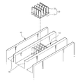
도 4는 본 발명에 따른 슬라이딩 창호용 필링피스의 저면 사시도,
도 5는 본 발명에 따른 슬라이딩 창호용 필링피스의 분해사시도,
도 6은 도 5의 I-I선 단면도 및 슬라이딩 창호용 필링피스의 설치상태도,
도 7은 본 발명에 따른 슬라이딩 창호용 필링피스의 다른 실시예이다.1 is a perspective view showing the structure of a typical sliding window;
Figure 2 is a perspective view showing the appearance of a peeling piece is inserted into a conventional window frame,
3 is an internal configuration diagram of part 'A' of FIG. 1;
Figure 4 is a bottom perspective view of a sliding piece for sliding windows and doors according to the present invention,
5 is an exploded perspective view of a sliding piece for sliding windows and doors according to the present invention,
6 is a cross-sectional view taken along line II of Figure 5 and a sliding piece for sliding windows and doors,
Figure 7 is another embodiment of a sliding piece for sliding windows and doors according to the present invention.
이하 첨부한 도면을 참조하여 본 발명의 바람직한 실시예에 대한 구성 및 작용을 상세히 설명하면 다음과 같다.DETAILED DESCRIPTION OF THE PREFERRED EMBODIMENTS Hereinafter, preferred embodiments of the present invention will be described in detail with reference to the accompanying drawings.
여기서, 각 도면의 구성요소들에 대해 참조부호를 부가함에 있어서 동일한 구성요소들에 한해서는 비록 다른 도면상에 표시되더라도 가능한 한 동일한 부호로 표기되었음에 유의하여야 한다.In the drawings, the same reference numerals as in the drawings denote the same elements in the drawings, unless they are indicated on other drawings.
도 4는 본 발명에 따른 슬라이딩 창호용 필링피스의 저면 사시도이고, 도 5는 본 발명에 따른 슬라이딩 창호용 필링피스의 분해사시도이며, 도 6은 본 발명에 따른 슬라이딩창호용 필링피스의 설치상태도이다.Figure 4 is a bottom perspective view of a sliding window and a filling piece for sliding windows according to the invention, Figure 5 is an exploded perspective view of a sliding window and a filling piece for sliding windows according to the present invention, Figure 6 is a view showing the installation state of the sliding window and peeling piece according to the present invention. .
도 4 및 도 5를 참조하면, 본 발명의 바람직한 일 실시예에 따른 슬라이딩 창호용 필링피스(100)는, 창틀프레임(10)의 대향면에 구비된 적어도 한 쌍의 레일(11) 사이에 끼움 결합되는 것으로, 창짝(20)을 완전히 닫았을 때 창짝(20)과 창짝(20)이 겹치는 부위의 상, 하단에 서로 대향되게 위치하게 된다. 즉 슬라이딩 창호의 경우 창짝(20)이 겹치는 부위가 상호 맞물리도록 설계되어 어느 정도 방음 및 단열효과를 얻을 수 있다.4 and 5, the sliding
이 경우 상기 겹치게 되는 창짝(20)의 상, 하단부는 창틀프레임(10)의 내향면으로부터 이격됨에 따라 그 사이에 틈새 공간(S)이 생길 수밖에 없다. 이에 따라, 창짝(20)이 완전히 닫혔을 때 창짝(20)이 겹치는 부위의 상,하측에 필링피스(100)를 삽입 설치하게 된다.In this case, as the upper and lower portions of the overlapping
여기서, 바람직하게는 상기 필링피스(100)는, 창틀프레임(10)의 내주면에 고정배치되는 몸체부(110)와, 상기 몸체부(110)의 일면에 수직을 이루도록 형성되되 복수개가 이격되게 배치되어 창짝(20)의 닫힘 시 틈새 공간(S)을 막아주는 분할편(120)과, 상기 몸체부(110)의 타면에 형성되는 적어도 하나의 결로수 배출유로(111)에 충진되어 결로수를 통과시켜줌과 아울러 기밀을 유지해주는 다공성 부재(130)를 포함하여 이루어질 수 있다.Here, preferably, the
이 경우 상기 분할편(120)은 연질의 고무 또는 실리콘 재질로 이루어져 창짝(20)의 슬라이딩 이동시 유연한 접힘 및 펼침이 이루어지게 된다.In this case, the
그리고 상기 결로수 배출유로(111)는 음각으로 형성되어 레일(11)과 레일(11) 사이에 존재하는 결로수를 일측으로 배출시켜주는 역할을 하게 된다. 여기서, 바람직하게는 상기 결로수 배출유로(111)는 지그재그(└┐) 형상으로 형성된다. 즉 외기가 지그재그로 형성된 배출유로(111)를 통해 유입되면서 어느 정도의 정체 시간을 가지게 되고, 이에 따라 외기의 유입을 최대한 차단시킬 수 있는 효과를 얻게 된다.In addition, the condensation
아울러 상기 다공성 부재(130)는 스폰지 또는 배플(Baffle) 재질, 바람직하게는 배플 재질로 이루어질 수 있다. 즉 이와 같은 다공성 부재(130)는 복수의 미세한 통공을 구비하고 있다. 따라서 외기는 최대한 차단해주면서 레일(11)과 레일(11) 사이에 존재하는 결로수를 일측으로 배출시켜줄 수 있게 된다.In addition, the
이와 같은 구조의 필링피스(100)는 주로 실내의 유리창에 맺힌 결로수가 흘러내려 모이게 되는 창틀프레임(10)의 적어도 하측 내주면에 설치되는 것이 바람직하다.
The
이와 같은 구성의 본 발명에 따른 슬라이딩 창호용 필링피스(100)는, 도 6에 도시된 바와 같이, 창틀프레임(10)의 대향면에 각각 구비된 한 쌍의 레일(11) 중 결로수(W)가 주로 흘러 모이게 되는 하부의 레일(11)에 설치되는 것이 바람직하다. 이에 따라 겨울철 결로현상에 의해 실내 유리창에 결로가 발생하여 레일(11)과 레일(11) 사이의 공간에 결로수(W)가 모이게 되더라도, 필링피스(100)의 저면에 구비된 결로수 배출유로(111)를 통과한 후 창틀프레임(10)의 일측 배출공(미도시) 측으로 용이하게 배출시킬 수 있게 된다.As shown in FIG. 6, in the sliding window
이 경우 결로수 배출유로(111)에 충진된 다공성 부재(130)에 의해 결로수는 통과시켜줌과 아울러 상기 결로수 배출유로(111)를 통해 실내로 유입되는 외기를 최대한 차단해줄 수 있게 됨으로써 기밀 성능을 향상시킬 수 있게 된다.
In this case, the condensation water is passed by the
이상에서는 본 발명을 특정의 바람직한 실시 예를 들어 도시하고 설명하였으나, 본 발명은 상기한 실시 예에 한정되지 않으며 본 발명의 기술사상을 벗어나지 않는 범위 내에서 다양한 변경과 수정이 가능함은 물론이다.While the present invention has been particularly shown and described with reference to exemplary embodiments thereof, it is to be understood that the invention is not limited to the disclosed exemplary embodiments, but, on the contrary, is intended to cover various modifications and equivalent arrangements included within the spirit and scope of the invention.
특히, 본 발명에서는 다공성 부재(130)가 몸체부(110)의 타면에 음각으로 형성된 결로수 배출유로(111)에 충진된 경우의 일례를 들어 도시하고 설명하였으나, 이에 한정되지 않으며 다양한 구조로 변경 적용될 수 있음은 물론이다.In particular, the present invention has been shown and described as an example of the case where the
예컨대, 도 7은 본 발명의 다른 실시예에 따른 슬라이딩 창호용 필링피스(100')를 보여주는 도면으로, 도면을 참조하면, 필링피스(100')는 다공성 부재(130)가 별도로 형성된 결로수 배출유로(111)에 충진 형성되는 구조가 아닌 소정의 두께로 이루어진 별도의 층이 적층된 구조로 이루어질 수 있음을 보여준다.For example, FIG. 7 is a view showing a sliding window peeling piece 100 'according to another embodiment of the present invention, referring to the drawing, the filling piece 100' is a condensation water discharge formed separately from the
이에 따라 좀더 많은 양의 결로수를 신속하게 일측으로 배출시킬 수 있음과 아울러 외기의 유입을 최대한 방지해줄 수 있게 된다.
Accordingly, a larger amount of condensate can be quickly discharged to one side, and the inflow of outside air can be prevented as much as possible.
10 : 창틀프레임 11 : 레일
20 : 창짝 100 : 필링피스
110 : 몸체부 111 : 결로수 배출유로
120 : 분할편 130 : 다공성 부재
S : 틈새 공간 W : 결로수10: frame frame 11: rail
20: window 100: peeling piece
110: body 111: condensation water discharge passage
120: segment 130: porous member
S: clearance space W: condensation
Claims (6)
상기 창틀프레임(10)의 내주면에 고정 배치되는 몸체부(110);
상기 몸체부(110)의 일면에 수직을 이루도록 형성되되 복수개가 이격되게 배치되어 상기 창짝(20)의 닫힘 시 상기 틈새 공간(S)을 막아주는 분할편(120); 및
상기 몸체부(110)의 타면에 형성되는 적어도 하나의 결로수 배출유로(111)에 충진되어 결로수를 통과시켜줌과 아울러 기밀을 유지해주는 다공성 부재(130);를 포함하여 구성된 것을 특징으로 하는 슬라이딩 창호용 필링피스.In the peeling piece for sliding windows and doors that prevent the gap space (S) between the window frame frame 10 and the window spear 20,
A body part 110 fixedly disposed on an inner circumferential surface of the window frame frame 10;
A split piece 120 formed to be perpendicular to one surface of the body part 110 and disposed to be spaced apart from each other to prevent the gap space S when the window 20 is closed; And
The porous member 130 is filled in the at least one condensation water discharge passage 111 formed on the other surface of the body portion 110 to pass the condensation water and maintain airtightness; Peeling pieces for windows and doors.
상기 결로수 배출유로(111)는,
지그재그(└┐) 형상으로 형성된 것을 특징으로 하는 슬라이딩 창호용 필링피스.The method of claim 1,
The condensation water discharge passage 111,
A sliding piece for sliding windows and doors, characterized in that formed in a zigzag shape.
상기 결로수 배출유로(111)는,
음각으로 형성된 것을 특징으로 하는 슬라이딩 창호용 필링피스.3. The method according to claim 1 or 2,
The condensation water discharge passage 111,
A sliding piece for sliding windows and doors, characterized in that formed intaglio.
상기 필링피스(100)는,
상기 창틀프레임(10)의 적어도 하측 내주면에 설치되는 것을 특징으로 하는 슬라이딩 창호용 필링피스.The method of claim 3,
The peeling piece 100,
Filling piece for sliding windows and doors, characterized in that installed on at least the lower inner peripheral surface of the window frame frame (10).
상기 창틀프레임(10)의 내주면에 고정 배치되는 몸체부(110);
상기 몸체부(110)의 일면에 수직을 이루도록 형성되되 복수개가 이격되게 배치되어 상기 창짝(20)의 닫힘 시 상기 틈새 공간을 막아주는 분할편(120); 및
상기 몸체부(110)의 타면에 적층 형성되어 결로수를 통과시켜줌과 아울러 기밀을 유지해주는 다공성 부재(130);를 포함하여 구성된 것을 특징으로 하는 슬라이딩 창호용 필링피스.In the peeling piece for sliding windows and doors that prevent the gap space (S) between the window frame frame 10 and the window spear 20,
A body part 110 fixedly disposed on an inner circumferential surface of the window frame frame 10;
A split piece (120) formed to be perpendicular to one surface of the body part (110) and disposed to be spaced apart from each other to prevent the gap space when the window is closed (20); And
And a porous member (130) formed on the other surface of the body (110) to be laminated to pass condensation water and to maintain airtightness.
상기 다공성 부재(130)는,
스폰지 또는 배플(Baffle) 재질인 것을 특징으로 하는 슬라이딩 창호용 필링피스.6. The method according to claim 1 or 5,
The porous member 130,
Filling piece for sliding windows and doors, characterized in that the sponge or baffle material.
Priority Applications (4)
| Application Number | Priority Date | Filing Date | Title |
|---|---|---|---|
| KR1020120088267A KR20140022151A (en) | 2012-08-13 | 2012-08-13 | Filling piece for sliding windows |
| RU2015104881/12A RU2589632C1 (en) | 2012-08-13 | 2013-08-12 | Insert for sliding window |
| CN201380042687.9A CN104541013B (en) | 2012-08-13 | 2013-08-12 | Filling member for sliding window |
| PCT/KR2013/007223 WO2014027806A1 (en) | 2012-08-13 | 2013-08-12 | Filling piece for sliding window |
Applications Claiming Priority (1)
| Application Number | Priority Date | Filing Date | Title |
|---|---|---|---|
| KR1020120088267A KR20140022151A (en) | 2012-08-13 | 2012-08-13 | Filling piece for sliding windows |
Publications (1)
| Publication Number | Publication Date |
|---|---|
| KR20140022151A true KR20140022151A (en) | 2014-02-24 |
Family
ID=50101318
Family Applications (1)
| Application Number | Title | Priority Date | Filing Date |
|---|---|---|---|
| KR1020120088267A KR20140022151A (en) | 2012-08-13 | 2012-08-13 | Filling piece for sliding windows |
Country Status (4)
| Country | Link |
|---|---|
| KR (1) | KR20140022151A (en) |
| CN (1) | CN104541013B (en) |
| RU (1) | RU2589632C1 (en) |
| WO (1) | WO2014027806A1 (en) |
Cited By (2)
| Publication number | Priority date | Publication date | Assignee | Title |
|---|---|---|---|---|
| KR101535383B1 (en) * | 2014-05-19 | 2015-07-08 | 합자회사 한양창호 | Windbreak and window system containing the same |
| KR20190002561U (en) * | 2018-04-04 | 2019-10-14 | 김석환 | Filling piece |
Family Cites Families (5)
| Publication number | Priority date | Publication date | Assignee | Title |
|---|---|---|---|---|
| US4408425A (en) * | 1981-08-10 | 1983-10-11 | Torme Helen M | Window moisture and air flow control device |
| KR960009688Y1 (en) * | 1993-05-04 | 1996-10-31 | 주식회사 엘지화학 | Window frame |
| KR200345035Y1 (en) * | 2003-12-16 | 2004-03-18 | 주식회사 엘지화학 | Piece for ceal of silding window |
| KR200400850Y1 (en) * | 2005-08-26 | 2005-11-09 | 투씨홈시스템 주식회사 | soundproofing-wind protection for window |
| KR100919284B1 (en) * | 2007-11-05 | 2009-09-30 | 안병욱 | Drainage device for window frame and construction process using the same |
-
2012
- 2012-08-13 KR KR1020120088267A patent/KR20140022151A/en active Search and Examination
-
2013
- 2013-08-12 WO PCT/KR2013/007223 patent/WO2014027806A1/en active Application Filing
- 2013-08-12 RU RU2015104881/12A patent/RU2589632C1/en active
- 2013-08-12 CN CN201380042687.9A patent/CN104541013B/en active Active
Cited By (2)
| Publication number | Priority date | Publication date | Assignee | Title |
|---|---|---|---|---|
| KR101535383B1 (en) * | 2014-05-19 | 2015-07-08 | 합자회사 한양창호 | Windbreak and window system containing the same |
| KR20190002561U (en) * | 2018-04-04 | 2019-10-14 | 김석환 | Filling piece |
Also Published As
| Publication number | Publication date |
|---|---|
| WO2014027806A1 (en) | 2014-02-20 |
| RU2589632C1 (en) | 2016-07-10 |
| CN104541013B (en) | 2016-09-07 |
| CN104541013A (en) | 2015-04-22 |
Similar Documents
| Publication | Publication Date | Title |
|---|---|---|
| KR101520149B1 (en) | Double sliding window | |
| KR101472189B1 (en) | Window having a ventilation structure | |
| JP4594817B2 (en) | Curtain wall window ventilation structure | |
| KR200406648Y1 (en) | Double adiabatic window for wind pressure resistance | |
| JP6557614B2 (en) | Joinery | |
| KR20140022151A (en) | Filling piece for sliding windows | |
| JP4694297B2 (en) | Ventilation structure in windows | |
| TWI709684B (en) | Shelter structure of building opening | |
| KR101583722B1 (en) | Multi rail windows improved airtight performance | |
| KR101112684B1 (en) | This is not the structure of the triple-sash windows | |
| KR101499623B1 (en) | Insulated window system | |
| KR101471244B1 (en) | Double sliding window | |
| JP7041458B2 (en) | Joinery | |
| US20180106097A1 (en) | Recessed Window Assembly and Corresponding Method | |
| JP2008111300A (en) | Sash | |
| KR20120124970A (en) | Window and door frame | |
| JP4032423B2 (en) | Lower frame flat sash | |
| JP2019527784A (en) | Draw joinery | |
| TWI499715B (en) | Doors and windows with waterproof devices and doors and windows | |
| JP6968555B2 (en) | Joinery | |
| KR102034572B1 (en) | Structure for smooth drainage and draft protection of the door frame with sliding door opening system | |
| JP7425671B2 (en) | fittings | |
| KR102280520B1 (en) | Glazing-Exchange Type ERV Air Vent Connecting Module | |
| TWI550179B (en) | Double drain structure for door jamb and window jamb | |
| JP4085865B2 (en) | Bottom frame structure of outdoor sash |
Legal Events
| Date | Code | Title | Description |
|---|---|---|---|
| A201 | Request for examination | ||
| E902 | Notification of reason for refusal | ||
| AMND | Amendment | ||
| AMND | Amendment |