KR20140022095A - Toner, two-component developer, and image forming method - Google Patents
Toner, two-component developer, and image forming method Download PDFInfo
- Publication number
- KR20140022095A KR20140022095A KR1020147000016A KR20147000016A KR20140022095A KR 20140022095 A KR20140022095 A KR 20140022095A KR 1020147000016 A KR1020147000016 A KR 1020147000016A KR 20147000016 A KR20147000016 A KR 20147000016A KR 20140022095 A KR20140022095 A KR 20140022095A
- Authority
- KR
- South Korea
- Prior art keywords
- toner
- less
- particles
- image
- mass
- Prior art date
Links
Images


Classifications
-
- G—PHYSICS
- G03—PHOTOGRAPHY; CINEMATOGRAPHY; ANALOGOUS TECHNIQUES USING WAVES OTHER THAN OPTICAL WAVES; ELECTROGRAPHY; HOLOGRAPHY
- G03G—ELECTROGRAPHY; ELECTROPHOTOGRAPHY; MAGNETOGRAPHY
- G03G9/00—Developers
- G03G9/08—Developers with toner particles
- G03G9/0819—Developers with toner particles characterised by the dimensions of the particles
-
- G—PHYSICS
- G03—PHOTOGRAPHY; CINEMATOGRAPHY; ANALOGOUS TECHNIQUES USING WAVES OTHER THAN OPTICAL WAVES; ELECTROGRAPHY; HOLOGRAPHY
- G03G—ELECTROGRAPHY; ELECTROPHOTOGRAPHY; MAGNETOGRAPHY
- G03G9/00—Developers
- G03G9/08—Developers with toner particles
-
- G—PHYSICS
- G03—PHOTOGRAPHY; CINEMATOGRAPHY; ANALOGOUS TECHNIQUES USING WAVES OTHER THAN OPTICAL WAVES; ELECTROGRAPHY; HOLOGRAPHY
- G03G—ELECTROGRAPHY; ELECTROPHOTOGRAPHY; MAGNETOGRAPHY
- G03G13/00—Electrographic processes using a charge pattern
- G03G13/06—Developing
- G03G13/08—Developing using a solid developer, e.g. powder developer
- G03G13/095—Removing excess solid developer
-
- G—PHYSICS
- G03—PHOTOGRAPHY; CINEMATOGRAPHY; ANALOGOUS TECHNIQUES USING WAVES OTHER THAN OPTICAL WAVES; ELECTROGRAPHY; HOLOGRAPHY
- G03G—ELECTROGRAPHY; ELECTROPHOTOGRAPHY; MAGNETOGRAPHY
- G03G15/00—Apparatus for electrographic processes using a charge pattern
- G03G15/06—Apparatus for electrographic processes using a charge pattern for developing
- G03G15/08—Apparatus for electrographic processes using a charge pattern for developing using a solid developer, e.g. powder developer
-
- G—PHYSICS
- G03—PHOTOGRAPHY; CINEMATOGRAPHY; ANALOGOUS TECHNIQUES USING WAVES OTHER THAN OPTICAL WAVES; ELECTROGRAPHY; HOLOGRAPHY
- G03G—ELECTROGRAPHY; ELECTROPHOTOGRAPHY; MAGNETOGRAPHY
- G03G21/00—Arrangements not provided for by groups G03G13/00 - G03G19/00, e.g. cleaning, elimination of residual charge
- G03G21/10—Collecting or recycling waste developer
-
- G—PHYSICS
- G03—PHOTOGRAPHY; CINEMATOGRAPHY; ANALOGOUS TECHNIQUES USING WAVES OTHER THAN OPTICAL WAVES; ELECTROGRAPHY; HOLOGRAPHY
- G03G—ELECTROGRAPHY; ELECTROPHOTOGRAPHY; MAGNETOGRAPHY
- G03G5/00—Recording members for original recording by exposure, e.g. to light, to heat, to electrons; Manufacture thereof; Selection of materials therefor
- G03G5/02—Charge-receiving layers
- G03G5/04—Photoconductive layers; Charge-generation layers or charge-transporting layers; Additives therefor; Binders therefor
- G03G5/05—Organic bonding materials; Methods for coating a substrate with a photoconductive layer; Inert supplements for use in photoconductive layers
-
- G—PHYSICS
- G03—PHOTOGRAPHY; CINEMATOGRAPHY; ANALOGOUS TECHNIQUES USING WAVES OTHER THAN OPTICAL WAVES; ELECTROGRAPHY; HOLOGRAPHY
- G03G—ELECTROGRAPHY; ELECTROPHOTOGRAPHY; MAGNETOGRAPHY
- G03G5/00—Recording members for original recording by exposure, e.g. to light, to heat, to electrons; Manufacture thereof; Selection of materials therefor
- G03G5/14—Inert intermediate or cover layers for charge-receiving layers
- G03G5/147—Cover layers
-
- G—PHYSICS
- G03—PHOTOGRAPHY; CINEMATOGRAPHY; ANALOGOUS TECHNIQUES USING WAVES OTHER THAN OPTICAL WAVES; ELECTROGRAPHY; HOLOGRAPHY
- G03G—ELECTROGRAPHY; ELECTROPHOTOGRAPHY; MAGNETOGRAPHY
- G03G9/00—Developers
- G03G9/08—Developers with toner particles
- G03G9/0802—Preparation methods
- G03G9/0804—Preparation methods whereby the components are brought together in a liquid dispersing medium
- G03G9/0806—Preparation methods whereby the components are brought together in a liquid dispersing medium whereby chemical synthesis of at least one of the toner components takes place
-
- G—PHYSICS
- G03—PHOTOGRAPHY; CINEMATOGRAPHY; ANALOGOUS TECHNIQUES USING WAVES OTHER THAN OPTICAL WAVES; ELECTROGRAPHY; HOLOGRAPHY
- G03G—ELECTROGRAPHY; ELECTROPHOTOGRAPHY; MAGNETOGRAPHY
- G03G9/00—Developers
- G03G9/08—Developers with toner particles
- G03G9/0802—Preparation methods
- G03G9/0808—Preparation methods by dry mixing the toner components in solid or softened state
-
- G—PHYSICS
- G03—PHOTOGRAPHY; CINEMATOGRAPHY; ANALOGOUS TECHNIQUES USING WAVES OTHER THAN OPTICAL WAVES; ELECTROGRAPHY; HOLOGRAPHY
- G03G—ELECTROGRAPHY; ELECTROPHOTOGRAPHY; MAGNETOGRAPHY
- G03G9/00—Developers
- G03G9/08—Developers with toner particles
- G03G9/0802—Preparation methods
- G03G9/081—Preparation methods by mixing the toner components in a liquefied state; melt kneading; reactive mixing
-
- G—PHYSICS
- G03—PHOTOGRAPHY; CINEMATOGRAPHY; ANALOGOUS TECHNIQUES USING WAVES OTHER THAN OPTICAL WAVES; ELECTROGRAPHY; HOLOGRAPHY
- G03G—ELECTROGRAPHY; ELECTROPHOTOGRAPHY; MAGNETOGRAPHY
- G03G9/00—Developers
- G03G9/08—Developers with toner particles
- G03G9/0802—Preparation methods
- G03G9/0815—Post-treatment
-
- G—PHYSICS
- G03—PHOTOGRAPHY; CINEMATOGRAPHY; ANALOGOUS TECHNIQUES USING WAVES OTHER THAN OPTICAL WAVES; ELECTROGRAPHY; HOLOGRAPHY
- G03G—ELECTROGRAPHY; ELECTROPHOTOGRAPHY; MAGNETOGRAPHY
- G03G9/00—Developers
- G03G9/08—Developers with toner particles
- G03G9/0802—Preparation methods
- G03G9/0817—Separation; Classifying
-
- G—PHYSICS
- G03—PHOTOGRAPHY; CINEMATOGRAPHY; ANALOGOUS TECHNIQUES USING WAVES OTHER THAN OPTICAL WAVES; ELECTROGRAPHY; HOLOGRAPHY
- G03G—ELECTROGRAPHY; ELECTROPHOTOGRAPHY; MAGNETOGRAPHY
- G03G9/00—Developers
- G03G9/08—Developers with toner particles
- G03G9/0821—Developers with toner particles characterised by physical parameters
-
- G—PHYSICS
- G03—PHOTOGRAPHY; CINEMATOGRAPHY; ANALOGOUS TECHNIQUES USING WAVES OTHER THAN OPTICAL WAVES; ELECTROGRAPHY; HOLOGRAPHY
- G03G—ELECTROGRAPHY; ELECTROPHOTOGRAPHY; MAGNETOGRAPHY
- G03G9/00—Developers
- G03G9/08—Developers with toner particles
- G03G9/0827—Developers with toner particles characterised by their shape, e.g. degree of sphericity
-
- G—PHYSICS
- G03—PHOTOGRAPHY; CINEMATOGRAPHY; ANALOGOUS TECHNIQUES USING WAVES OTHER THAN OPTICAL WAVES; ELECTROGRAPHY; HOLOGRAPHY
- G03G—ELECTROGRAPHY; ELECTROPHOTOGRAPHY; MAGNETOGRAPHY
- G03G9/00—Developers
- G03G9/08—Developers with toner particles
- G03G9/087—Binders for toner particles
-
- G—PHYSICS
- G03—PHOTOGRAPHY; CINEMATOGRAPHY; ANALOGOUS TECHNIQUES USING WAVES OTHER THAN OPTICAL WAVES; ELECTROGRAPHY; HOLOGRAPHY
- G03G—ELECTROGRAPHY; ELECTROPHOTOGRAPHY; MAGNETOGRAPHY
- G03G9/00—Developers
- G03G9/08—Developers with toner particles
- G03G9/087—Binders for toner particles
- G03G9/08742—Binders for toner particles comprising macromolecular compounds obtained otherwise than by reactions only involving carbon-to-carbon unsaturated bonds
- G03G9/08755—Polyesters
-
- G—PHYSICS
- G03—PHOTOGRAPHY; CINEMATOGRAPHY; ANALOGOUS TECHNIQUES USING WAVES OTHER THAN OPTICAL WAVES; ELECTROGRAPHY; HOLOGRAPHY
- G03G—ELECTROGRAPHY; ELECTROPHOTOGRAPHY; MAGNETOGRAPHY
- G03G9/00—Developers
- G03G9/08—Developers with toner particles
- G03G9/097—Plasticisers; Charge controlling agents
- G03G9/09708—Inorganic compounds
-
- G—PHYSICS
- G03—PHOTOGRAPHY; CINEMATOGRAPHY; ANALOGOUS TECHNIQUES USING WAVES OTHER THAN OPTICAL WAVES; ELECTROGRAPHY; HOLOGRAPHY
- G03G—ELECTROGRAPHY; ELECTROPHOTOGRAPHY; MAGNETOGRAPHY
- G03G9/00—Developers
- G03G9/08—Developers with toner particles
- G03G9/10—Developers with toner particles characterised by carrier particles
- G03G9/107—Developers with toner particles characterised by carrier particles having magnetic components
Landscapes
- Physics & Mathematics (AREA)
- General Physics & Mathematics (AREA)
- Chemical & Material Sciences (AREA)
- Inorganic Chemistry (AREA)
- Chemical Kinetics & Catalysis (AREA)
- Spectroscopy & Molecular Physics (AREA)
- Life Sciences & Earth Sciences (AREA)
- Engineering & Computer Science (AREA)
- Environmental & Geological Engineering (AREA)
- Sustainable Development (AREA)
- Developing Agents For Electrophotography (AREA)
- Photoreceptors In Electrophotography (AREA)
Abstract
본 발명은 중량-평균 입경(D4)이 3.0㎛ 이상 8.0㎛ 이하인 토너에 관한 것이며, 여기서 원 상당 직경이 1.98㎛ 이상 200.00㎛ 미만인 토너의 입자를 원형도 0.200 이상 1.000 이하 범위내로 800개로 분할하여 분석한 평균 원형도가 0.960 이상 0.985 이하이며, 원형도가 0.990 이상 1.000 이하인 입자 A의 비율이 입자 개수에 대하여 25.0% 이하이고, 원 상당 직경이 0.50㎛ 이상 200.00㎛ 미만인 전체 입자에 대한 원 상당 직경이 0.50㎛ 이상 1.98㎛ 미만인 입자 B의 비가 입자 개수에 대하여 10.0% 이하이다.The present invention relates to a toner having a weight-average particle diameter (D4) of 3.0 µm or more and 8.0 µm or less, wherein the particles of the toner having a circle equivalent diameter of 1.98 µm or more and less than 200.00 µm are divided into 800 pieces in the range of 0.200 to 1.000 circularity and analyzed The proportion of particles A having an average circularity of 0.960 or more and 0.985 or less, circularity of 0.990 or more and 1.000 or less is 25.0% or less with respect to the number of particles, and the circle equivalent diameter for all particles having a circle equivalent diameter of 0.50 μm or more and less than 200.00 μm The ratio of particle | grains B which are 0.50 micrometer or more and less than 1.98 micrometers is 10.0% or less with respect to particle number.
Description
본 발명은 전자사진 방식, 정전 기록 방식, 정전 인쇄 방식 또는 토너-제트 방식에 사용되는 토너, 토너를 함유하는 2성분 현상제 및 토너를 사용한 화상 형성 방법에 관한 것이다.The present invention relates to a toner used in an electrophotographic method, an electrostatic recording method, an electrostatic printing method or a toner-jet method, a two-component developer containing a toner, and an image forming method using the toner.
전자사진 장치에서 장기간 동안 양호한 화상 특성을 실현하기 위하여, 양호한 전사성 및 양호한 클리닝성 모두를 갖는 토너가 요구된다. 이를 위하여, 특정 형상을 갖는 토너 입자의 분포 상태를 제어하는 것이 지금까지 실시되어 왔다.In order to realize good image characteristics for an extended period of time in an electrophotographic apparatus, a toner having both good transferability and good cleaning property is required. To this end, controlling the distribution state of toner particles having a specific shape has been practiced up to now.
특허문헌 1에서, 토너 입자 중 원 상당 직경이 3.00㎛ 이상인 토너 입자의 평균 원형도 및 원형도 분포를 규정하여 양호한 전사성 및 양호한 클리닝성 모두를 실현하고자 하였다.In
특허문헌 2에서, 입경이 2㎛ 이상 5㎛ 이하인 토너 입자 중에서 원형도가 0.950 이하인 토너 입자의 개수 비율을 40% 이하로 제어하여 작은 입경을 갖는 토너 입자의 형상을 최적화함으로써 전사 효율이 개선되며 그리고 더 높은 화질이 달성된다.In
특허문헌 1에 기재된 토너는 평균 원형도가 작으며, 토너의 전사성 및 현상성은 추가로 개선될 수 있다.The toner described in
추가로, 특허문헌 2에 개시된 토너에 대하여 본 발명의 발명자들이 예의 검토한 결과에 의하면, 토너가 2㎛ 미만의 입경을 갖는 토너 입자를 다량 함유하며 화상이 인자 화상 비율 40%의 조건하에서 10,000매 이상 프린트하는 경우, 토너 소모가 자성 캐리어의 위에서 발생하며, 그리하여 화상 농도가 감소될 수 있다.Further, the inventors of the present invention intensively examined the toner disclosed in
본 발명은 양호한 전사 효율 및 양호한 클리닝성을 가지며, 다수매를 복사 또는 인쇄할 때 화상 농도에서의 변화가 억제되며, 그리하여 내스트레스성이 양호한 토너를 제공한다. 본 발명은 추가로 2성분 현상제 및 토너를 사용한 화상 형성 방법을 제공한다.The present invention has good transfer efficiency and good cleaning property, and changes in image density are suppressed when copying or printing a plurality of sheets, thereby providing a toner having good stress resistance. The present invention further provides an image forming method using a two-component developer and a toner.
본 발명은 결착 수지 및 왁스를 각각 함유하는 토너 입자; 및 무기 미립자를 포함하며, 여기서The present invention provides toner particles each containing a binder resin and a wax; And inorganic particulates, wherein
(i) 토너의 중량-평균 입경(D4)이 3.0㎛ 이상 8.0㎛ 이하이고,(i) the weight-average particle diameter (D4) of the toner is 3.0 µm or more and 8.0 µm or less,
(ii) 화상 처리 해상도 512×512 화소의 플로우식 입자 상 측정 장치를 사용한 측정에서, 토너가 하기 조건 (a) 및 (b)를 충족하며:(ii) In the measurement using the flow particle image measuring apparatus having an image processing resolution of 512 x 512 pixels, the toner satisfies the following conditions (a) and (b):
(a) 원 상당 직경이 1.98㎛ 이상 200.00㎛ 미만이고, 토너의 평균 원형도가 0.960 이상 0.985 이하이며, 원형도가 0.990 이상 1.000 이하인 입자의 비율이 입자 개수에 대하여 25.0% 이하이고, (a) the proportion of particles having a circle equivalent diameter of 1.98 µm or more and less than 200.00 µm, an average circularity of toner of 0.960 or more and 0.985 or less, and a circularity of 0.990 or more and 1.000 or less, 25.0% or less with respect to the number of particles,
(b) 원 상당 직경이 0.50㎛ 이상 200.00㎛ 미만인 입자에 대한 원 상당 직경이 0.50㎛ 이상 1.98㎛ 미만인 입자의 비가 입자 개수에 대하여 10.0% 이하이고; (b) the ratio of particles having a circle equivalent diameter of 0.50 µm or more and less than 1.98 µm to particles having a circle equivalent diameter of 0.50 µm or more and less than 200.00 µm is 10.0% or less with respect to the number of particles;
(iii) 하기 수학식 1의 관계를 충족하는 토너를 제공한다:(iii) toner that satisfies the relationship of the following equation (1):
<수학식 1>&Quot; (1) "
1.20≤P1/P2≤2.001.20≤P1 / P2≤2.00
(상기 수학식에서, P1은 Pa/Pb이고, P2는 Pc/Pd이며,(In the above formula, P1 is Pa / Pb, P2 is Pc / Pd,
Pa 및 Pb는 각각 45°의 적외광 입사각에서 ATR 결정으로서 게르마늄(Ge)을 사용하는 감쇠 전반사(ATR) 방법에 의하여 측정한 토너의 푸리에 변환 적외선(FT-IR) 스펙트럼에서 2,843 ㎝-1 이상 2,853 ㎝-1 이하 범위내의 최대 흡수 피크 강도, 1,713 ㎝-1 이상 1,723 ㎝-1 이하 범위내의 최대 흡수 피크 강도를 나타내며,Pa and Pb are 2,843 cm -1 or more in the Fourier Transform Infrared (FT-IR) spectrum of the toner measured by attenuated total reflection (ATR) method using germanium (Ge) as an ATR crystal at an infrared light incident angle of 45 °, respectively. Maximum absorption peak intensity within a range of cm −1 or less, maximum absorption peak intensity within a range of 1,713 cm −1 or more and 1,723 cm −1 or less,
Pc 및 Pd는 각각 45°의 적외광 입사각에서 ATR 결정으로서 KRS5를 사용한 ATR 방법에 의하여 측정한 토너의 FT-IR 스펙트럼에서 2,843 ㎝-1 이상 2,853 ㎝-1 이하 범위내의 최대 흡수 피크 강도 및 1,713 ㎝-1 이상 1,723 ㎝-1 이하 범위내의 최대 흡수 피크 강도를 나타냄).Pc and Pd are the maximum absorption peak intensity and 1,713 cm in the range of 2,843 cm -1 or more and 2,853 cm -1 or less in the FT-IR spectrum of the toner measured by the ATR method using KRS5 as the ATR crystal at an infrared light incident angle of 45 °, respectively. Maximum absorption peak intensity within a range from -1 to 1,723 cm -1 or less).
본 발명은 2성분 현상제 및 토너를 사용한 화상 형성 방법을 제공한다.The present invention provides an image forming method using a two-component developer and a toner.
본 발명은 양호한 내구성을 지니며, 양호한 전사 효율 및 양호한 클리닝성 모두를 실현하는 토너를 제공할 수 있다.The present invention can provide a toner having good durability and realizing both good transfer efficiency and good cleaning property.
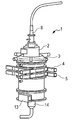
도 1은 열 처리 장치의 플로우를 도시하는 개략도이다.
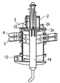
도 2a 내지 도 2c는 열 처리 장치를 도시하는 도면이다.
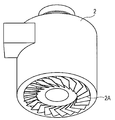
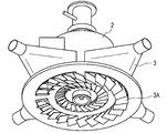
도 3은 열풍 공급 유닛(2) 및 기류 조정부(2A)의 일례를 도시하는 부분 단면 사시도이다.
도 4는 제1 냉풍 공급 유닛(3) 및 기류 조정부(3A)의 일례를 도시하는 부분 단면 사시도이다.
도 5는 현재까지 사용되어온 열 처리 장치를 도시하는 도면이다.1 is a schematic diagram illustrating a flow of a heat treatment apparatus.
2A to 2C are views showing a heat treatment apparatus.
3 is a partial cross-sectional perspective view showing an example of the hot
4 is a partial cross-sectional perspective view showing an example of the first cold
5 is a view showing a heat treatment apparatus that has been used up to now.
본 발명에 의한 토너는 중량-평균 입경(D4)이 3.0㎛ 이상 8.0㎛ 이하이고, 토너는 512×512 화소(화소당 0.37㎛×0.37㎛)의 화상 처리 해상도를 갖는 플로우식 입자 상 측정 장치를 사용한 측정에서 (a) 원 상당 직경이 1.98㎛ 이상 200.00㎛ 미만인 입자에 대하여 평균 원형도가 0.960 이상 0.985 이하이며, 원형도가 0.990 이상 1.000 이하인 입자의 비율이 입자 개수에 대하여 25.0% 이하인 입자인 조건을 충족한다. 더욱 바람직하게는, 토너의 평균 원형도는 0.960 이상 0.975 이하이고, 원형도가 0.990 이상 1.000 이하인 입자의 비율은 입자 개수에 대하여 20.0% 이하이다.The toner according to the present invention has a weight-average particle diameter (D4) of 3.0 µm or more and 8.0 µm or less, and the toner has a flow particle image measuring apparatus having an image processing resolution of 512 x 512 pixels (0.37 µm x 0.37 µm per pixel). In the measurement used, (a) the conditions where the average circularity was 0.960 or more and 0.985 or less, and the proportion of particles having a roundness of 0.990 or more and 1.000 or less was 25.0% or less with respect to the number of particles for particles having a circle equivalent diameter of 1.98 µm or more and less than 200.00 µm. To meet. More preferably, the average circularity of the toner is 0.960 or more and 0.975 or less, and the proportion of particles having a roundness of 0.990 or more and 1.000 or less is 20.0% or less with respect to the number of particles.
구체와 유사한 형상을 갖는 토너 입자는 상 담지 부재(감광 부재)와의 접촉 면적이 작아서 불규칙한 형상을 갖는 토너 입자에 비하여 감광 부재에 대한 접착력이 낮다. 게다가, 토너 입자의 형상은 구체에 근접하므로 전사 단계에서 형성된 전기장에 관하여서는, 전기장이 보다 균일하게 적용되며, 토너 입자는 전사재에 더 용이하게 전사된다. 그러한 이유로, 일반적으로, 토너 입자의 형상이 구체 형상에 근접하므로, 전사 효율은 더 높게 된다. 반대로, 토너 입자의 형성은 구체 형상에 근접하므로, 토너와 클리닝 블레이드 사이의 접촉 면적은 더 작게 된다. 그 결과, 상 담지 부재의 위의 전사 잔여 토너를 클리닝 블레이드로 긁어내는 것이 곤란하여 클리닝성이 감소된다. 그러므로, 전사성 및 클리닝성 사이에는 어느 정도로 트레이드-오프(trade-off) 관계가 있으며, 양호한 전사성 및 양호한 클리닝성 모두를 실현하는 것이 곤란하다. 특히, 원형도가 0.990 이상인 입자의 비율은 클리닝성의 감소에 영향을 미친다. 그러나, 원형도가 0.990 이상인 입자의 비율과 평균 원형도 사이에는 양의 상관관계가 존재한다. 원형도가 0.990 이상인 입자의 비율이 감소될 경우, 평균 원형도도 또한 감소되어 전사성이 감소된다. 따라서, 양호한 전사성 및 양호한 클리닝성을 모두 실현하기 위하여, 토너의 평균 원형도 및 원형도 분포를 적절한 범위내로 제어하여야만 한다.Toner particles having a shape similar to a sphere have a small contact area with the image bearing member (photosensitive member) and thus have a lower adhesive force to the photosensitive member than toner particles having an irregular shape. In addition, since the shape of the toner particles is close to the sphere, with respect to the electric field formed in the transfer step, the electric field is applied more uniformly, and the toner particles are more easily transferred to the transfer material. For that reason, in general, since the shape of the toner particles is close to the spherical shape, the transfer efficiency is higher. In contrast, the formation of the toner particles is close to the spherical shape, so that the contact area between the toner and the cleaning blade is smaller. As a result, it is difficult to scrape off the transfer residual toner on the image bearing member with the cleaning blade, thereby reducing the cleaning property. Therefore, there is a trade-off relationship between the transferability and the cleaning property to some extent, and it is difficult to realize both good transferability and good cleaning property. In particular, the proportion of particles having a roundness of 0.990 or more affects the reduction in cleaning properties. However, there is a positive correlation between the proportion of particles having a circularity of 0.990 or greater and the average circularity. If the proportion of the particles having a roundness of 0.990 or more is reduced, the average circularity is also reduced to reduce the transferability. Therefore, in order to realize both good transferability and good cleaning property, the average circularity and circularity distribution of the toner must be controlled within an appropriate range.
본 발명의 발명자들이 예의 검토한 결과, 평균 원형도가 0.960 이상 0.985 이하이고, 원형도가 0.990 이상 1.000 이하인 입자의 비율이 입자 개수에 대하여 25.0% 이하일 때, 높은 전사 효율 및 양호한 클리닝성이 달성될 수 있는 것으로 밝혀졌다.As a result of earnest examination by the inventors of the present invention, when the ratio of particles having an average circularity of 0.960 or more and 0.985 or less and a circularity of 0.990 or more and 1.000 or less is 25.0% or less with respect to the number of particles, high transfer efficiency and good cleaning property can be achieved. It turns out that you can.
이에 대한 이유는 하기와 같다. 일반적으로, 토너 중에서 원형도가 0.990 이상 1.000 이하인 입자의 비율이 클수록, 토너의 원형도 분포는 넓다. 원형도 분포가 넓은 토너를 사용한 경우, 평균 원형도가 동일하며 그리고 원형도 분포가 더 좁은 토너를 사용할 경우에 비하여 구체와 유사한 형상을 갖는 다수의 토너 입자가 전사 잔여 토너 중에 존재한다. 구체와 유사한 형상을 갖는 토너 입자는 클리닝 블레이드의 갭을 쉽게 통과하며, 그리하여 대전 롤러를 오염시킨다. 그래서, 상 담지 부재의 위에서 고르지 못한 대전으로 인한 화상 결함이 발생하는 경향이 있다.The reason for this is as follows. In general, the larger the proportion of particles having a roundness of 0.990 or more and 1.000 or less in the toner, the wider the distribution of the roundness of the toner. When toners having a wide circularity distribution are used, a large number of toner particles having a shape similar to a sphere are present in the transfer residual toner as compared with the case where toners having the same circularity distribution and the narrower circularity distribution are used. Toner particles having a shape similar to a sphere easily pass through the gap of the cleaning blade, thereby contaminating the charging roller. Thus, there is a tendency for image defects due to uneven charging on the image bearing member.
반대로, 원형도 분포가 좁은 상기 기재된 토너를 사용하는 경우, 구체와 유사한 형상을 갖는 전사 잔여 토너 입자의 양은 원형도 분포가 넓은 토너를 사용하는 경우보다 더 작다. 그 결과, 원형도 분포가 좁은 토너를 사용하는 경우, 대부분의 전사 잔여 토너 입자는 블레이드로 긁어내며, 양호한 클리닝성이 실현될 수 있다. 원형도가 0.990 이상 1.000 이하인 입자의 비율이 입자 개수에 대하여 25.0%를 초과할 경우, 구체와 유사한 형상을 갖는 토너 입자의 양은 크기 때문에 클리닝성이 감소된다.In contrast, when using the above-described toner having a narrow circularity distribution, the amount of transfer residual toner particles having a shape similar to a sphere is smaller than when using a toner having a large circularity distribution. As a result, when using a toner having a narrow circularity distribution, most transfer residual toner particles are scraped off with a blade, and good cleaning property can be realized. When the proportion of particles having a roundness of 0.990 or more and 1.000 or less exceeds 25.0% with respect to the number of particles, the amount of toner particles having a shape similar to that of a sphere is large, so the cleaning property is reduced.
평균 원형도가 0.960 미만인 경우, 형상이 불규칙한 다량의 토너 입자가 존재한다. 따라서, 다량의 전사 잔여 토너가 상 담지 부재의 위에 잔존하며, 전사 효율은 충분치 않다. 또한, 화상 출력시, 충분한 화상 농도를 얻는데 필요한 토너량은 증가되며, 이는 유지비면에서 이롭지 않다. 평균 원형도가 0.985를 초과하는 경우, 전사 효율은 충분하다. 그러나, 구체와 유사한 형상을 갖는 토너 입자의 양이 크므로, 전사 잔여 토너는 상 담지 부재 및 클리닝 블레이드 사이의 갭을 쉽게 통과한다. 그래서, 전사 잔여 토너는 상 담지 부재의 위에 잔존한다. 그 결과, 전사 잔여 토너는 대전 롤러를 오염시키며, 이는 상 담지 부재의 대전 실패를 초래할 수 있다. 게다가, 상 담지 부재 위의 전사 잔여 토너로 인하여 상 담지 부재 위에서의 고르지 못한 대전에 의하여 화상 형성 중에 화상 결함이 야기될 수 있다. 상 담지 부재의 최표면이 클리닝 블레이드로 긁어낼 수 없는 경우 특히 이러한 현상이 상당하게 발생된다.If the average circularity is less than 0.960, a large amount of toner particles having irregular shapes are present. Therefore, a large amount of transfer residual toner remains on the image bearing member, and the transfer efficiency is insufficient. In addition, in the image output, the amount of toner required to obtain sufficient image density is increased, which is not advantageous in terms of maintenance cost. If the average circularity exceeds 0.985, the transfer efficiency is sufficient. However, since the amount of toner particles having a shape similar to that of the sphere is large, the transfer residual toner easily passes through the gap between the image bearing member and the cleaning blade. Thus, the transfer residual toner remains on the image bearing member. As a result, the transfer residual toner contaminates the charging roller, which may cause the charging failure of the image bearing member. In addition, image defects may be caused during image formation by uneven charging on the image bearing member due to transfer residual toner on the image bearing member. This phenomenon is particularly significant when the outermost surface of the image bearing member cannot be scraped off with the cleaning blade.
본 발명의 토너에 의하면, 하기 조건 (b)는 화상 처리 해상도 512×512 화소(화소당 0.37㎛×0.37㎛)의 플로우식 입자 상 측정 장치를 사용한 측정에서 충족된다: (b) 원 상당 직경이 0.50㎛ 이상 200.00㎛ 미만인 입자에 대한 원 상당 직경이 0.50㎛ 이상 1.98㎛ 미만인 입자의 비는 입자 개수에 대하여 10.0% 이하이다. 조건 (b)에서, 원 상당 직경이 0.50㎛ 이상 1.98㎛ 미만인 입자의 비율은 입자 개수에 대하여 7.0% 이하인 것이 더욱 바람직하다.According to the toner of the present invention, the following condition (b) is satisfied in the measurement using a flow particle image measuring apparatus having an image processing resolution of 512 × 512 pixels (0.37 μm × 0.37 μm per pixel): (b) a circle equivalent diameter The ratio of the particle | grains whose circle equivalent diameter is 0.50 micrometer or more and less than 1.98 micrometers with respect to particle | grains 0.50 micrometer or more and less than 200.00 micrometer is 10.0% or less with respect to particle number. Under the condition (b), the proportion of particles having a circle equivalent diameter of 0.50 µm or more and less than 1.98 µm is more preferably 7.0% or less with respect to the number of particles.
원 상당 직경이 0.50㎛ 이상 1.98㎛ 미만인 입자의 비율이 입자 개수에 대하여 10.0% 이하인 경우, 본 발명의 토너를 2성분 현상제로서 사용할 경우 자성 캐리어의 표면에서의 토너 소모를 억제할 수 있다. 따라서, 자성 캐리어의 마찰 대전 부여 성질의 감소를 억제할 수 있다. 그래서, 현상제의 수명 연장은 다량의 토너가 소비되는 경우 높은 인자 비율(인자 화상 비율 40% 이상)에서 장기간 내구(다수매의 화상 형성이 실시됨)에서 특히 현상제의 수명 연장이 달성될 것이다.When the proportion of particles having a circle equivalent diameter of 0.50 µm or more and less than 1.98 µm is 10.0% or less with respect to the number of particles, toner consumption on the surface of the magnetic carrier can be suppressed when the toner of the present invention is used as a two-component developer. Therefore, it is possible to suppress the decrease in the frictional charge imparting property of the magnetic carrier. Thus, the life extension of the developer will be achieved especially in the long term durability (multiple image forming is performed) at a high printing ratio (factor image ratio of 40% or more) when a large amount of toner is consumed.
반대로, 원 상당 직경이 0.50㎛ 이상 1.98㎛ 미만인 입자의 비율이 입자 개수에 대하여 10.0%를 초과할 경우, 높은 인자 비율(인자 화상 비율: 40% 이상)에서의 장기 내구에서 현상기내의 스트레스에 의하여 원 상당 직경이 0.50㎛ 이상 1.98㎛ 미만인 입자가 자성 캐리어의 표면을 소모한다. 그 결과, 자성 캐리어의 마찰 대전 부여 성질이 감소되며, 그리하여 토너의 마찰 대전량을 감소시키게 된다. 따라서, 화상 농도의 감소, 비화상부에서의 포깅 및, 현상기내에서 토너의 산란이 발생할 수 있다.On the contrary, when the proportion of particles having a circle equivalent diameter of 0.50 µm or more and less than 1.98 µm exceeds 10.0% with respect to the number of particles, it is caused by stress in the developing device at long term durability at high factor ratio (factor image ratio: 40% or more). Particles having a circle equivalent diameter of 0.50 µm or more and less than 1.98 µm consume the surface of the magnetic carrier. As a result, the triboelectric charge imparting property of the magnetic carrier is reduced, thereby reducing the triboelectric charge amount of the toner. Therefore, a decrease in image density, fogging in non-image portions, and scattering of toner in a developer may occur.
지금까지, 평균 원형도가 0.960 이상 0.985 이하이고 그리고 입자 개수에 대한 원형도가 0.990 이상인 토너 입자의 비는 25.0% 이하로 억제되고, 원 상당 직경이 0.50㎛ 이상 1.98㎛ 미만인 토너 입자의 입자 개수에 대한 비는 10.0% 이하로 억제시킨 토너를 얻는 것은 매우 곤란하였다.To date, the ratio of toner particles having an average circularity of 0.960 or more and 0.985 or less and a circularity of 0.990 or more with respect to the number of particles is suppressed to 25.0% or less, and a circle equivalent diameter is applied to the particle number of toner particles having a diameter of 0.50 μm or more and less than 1.98 μm. It was very difficult to obtain a toner in which the ratio was less than 10.0%.
예를 들면, 토너 입자를 유화 응집법에 의하여 생성하는 경우, 평균 원형도가 0.960 이상 0.985 이하이고 그리고 원형도가 0.990 이상인 입자의 비가 입자 개수에 대하여 25.0% 이하인 토너를 얻을 수 있다. 그러나, 토너 입자를 유화 응집법에 의하여 제조하는 경우, 원 상당 직경이 0.50㎛ 이상 1.98㎛ 미만인 토너 입자의 비는 입자 개수에 대하여 10.0%를 초과한다. 이는 토너의 제조 공정에서 발생된 잔류 유화 입자로 인한 것이다. 반대로, 현탁 중합법에 의하여 얻은 토너 입자를 함유하는 토너에 관하여, 평균 원형도는 매우 높으며, 원형도가 0.990 이상인 토너 입자의 비는 또한 입자 개수에 대하여 25.0%를 초과한다. For example, when toner particles are produced by the emulsion coagulation method, toners having an average circularity of 0.960 or more and 0.985 or less and a ratio of particles having a circularity of 0.990 or more can be obtained by 25.0% or less with respect to the number of particles. However, when toner particles are produced by emulsion coagulation, the ratio of toner particles having a circle equivalent diameter of 0.50 µm or more and less than 1.98 µm exceeds 10.0% with respect to the number of particles. This is due to residual emulsified particles generated in the manufacturing process of the toner. In contrast, with respect to toners containing toner particles obtained by suspension polymerization, the average circularity is very high, and the ratio of toner particles having a roundness of 0.990 or more also exceeds 25.0% by number of particles.
공지의 분쇄법에 의하여 얻은 토너 입자를 함유하는 토너에 관하여, 평균 원형도는 0.960 미만이다. 분쇄법에 의하여 얻은 토너 입자를 함유하는 토너의 평균 원형도를 증가시키는 방법의 일례로는 열 처리 장치를 사용한 토너 입자의 구형화가 있다. 그러나, 통상의 열 처리 장치를 사용하는 경우, 생성된 토너의 평균 원형도는 0.960 이상 0.985 이하이기는 하나, 원형도가 0.990 이상인 입자의 비율은 입자 개수에 대하여 25%를 초과한다. 이에 대한 이유는 하기에서 구체적으로 기재할 것이다.As for the toner containing toner particles obtained by a known grinding method, the average circularity is less than 0.960. One example of a method of increasing the average circularity of a toner containing toner particles obtained by the grinding method is spheronization of the toner particles using a heat treatment apparatus. However, in the case of using a conventional heat treatment apparatus, although the average circularity of the produced toner is 0.960 or more and 0.985 or less, the proportion of particles having a circularity of 0.990 or more exceeds 25% with respect to the number of particles. The reason for this will be described in detail below.
더욱이, 본 발명의 토너는 하기 수학식 1의 관계를 충족한다:Moreover, the toner of the present invention satisfies the relationship of the following equation:
<수학식 1>&Quot; (1) "
1.20≤P1/P2≤2.001.20≤P1 / P2≤2.00
(상기 수학식에서, P1은 Pa/Pb이고, P2는 Pc/Pd이고, Pa 및 Pb는 각각 45°의 적외광 입사각에서 ATR 결정으로서 Ge을 사용하는 ATR 방법에 의하여 측정한 토너의 FT-IR 스펙트럼에서 2,843 ㎝-1 이상 2,853 ㎝-1 이하 범위내의 최대 흡수 피크 강도 및 1,713 ㎝-1 이상 1,723 ㎝-1 이하 범위내의 최대 흡수 피크 강도를 나타내며, Pc 및 Pd는 각각 45°의 적외광 입사각에서 ATR 결정으로서 KRS5를 사용하는 ATR 방법에 의하여 측정한 토너의 FT-IR 스펙트럼에서 2,843 ㎝-1 이상 2,853 ㎝-1 이하 범위내의 최대 흡수 피크 강도 및 1,713 ㎝-1 이상 1,723 ㎝-1 이하 범위내의 최대 흡수 피크 강도를 나타냄).(In the above equation, P1 is Pa / Pb, P2 is Pc / Pd, and Pa and Pb are the FT-IR spectra of the toner measured by the ATR method using Ge as the ATR crystal at an infrared light incident angle of 45 °, respectively. in denotes the maximum absorption peak intensity in the maximum absorption peak intensity and 1,713 ㎝ -1 over 1,723 ㎝ -1 or less within the range of 2,843 or more 2,853 ㎝ ㎝ -1 -1 or less range, Pc and Pd from the ATR infrared light incident angle of 45 °, respectively Maximum absorption peak intensity within the range of 2,843 cm -1 to 2,853 cm -1 and the maximum absorption within the range of 1,713 cm -1 to 1,723 cm -1 in the FT-IR spectrum of the toner measured by the ATR method using KRS5 as the crystal Peak intensity).
P1은 토너의 표면으로부터 토너 중심부로 연장되는 토너의 깊이 방향으로 토너 표면으로부터 약 0.3㎛ 떨어진 위치에서 결착 수지에 대한 왁스의 존재 비율에 관한 지수이며, P2는 토너 표면으로부터 약 1.0㎛ 떨어진 위치에서 결착 수지에 대한 왁스의 존재 비율에 관한 지수이다.P1 is an index relating to the ratio of wax to binder resin at a position about 0.3 μm away from the toner surface in the depth direction of the toner extending from the surface of the toner to the center of the toner, and P2 is a binder at a position about 1.0 μm away from the surface of the toner. It is an index relating to the ratio of wax to resin.
본 발명에서, 토너 표면으로부터 약 0.3㎛ 떨어진 위치에서 결착 수지에 대한 왁스의 존재 비율에 대한 지수 P1은 토너 표면으로부터 약 1.0㎛ 떨어진 위치에서 결착 수지에 대한 왁스의 존재 비율에 대한 지수 P2보다 더 크도록 제어되어 존재 비율에 관한 지수비[P1/P2](즉, 토너 표면으로부터 토너 중심부로 연장되는 토너의 깊이 방향으로 왁스의 고르지 않은 분포도)를 제어한다. 토너의 내구성은 하기 기재한 바와 같이 비[P1/P2]를 상기 범위내로 제어하여 개선될 수 있는 것으로 여겨진다.In the present invention, the index P1 for the presence ratio of wax to the binder resin at a position about 0.3 μm away from the toner surface is larger than the index P2 for the ratio of wax to the binder resin at a position about 1.0 μm away from the toner surface To control the index ratio [P1 / P2] (i.e., uneven distribution of wax in the depth direction of the toner extending from the toner surface to the center of the toner) relative to the presence ratio. It is believed that the durability of the toner can be improved by controlling the ratio [P1 / P2] within the above range as described below.
토너로부터 왁스의 삼출을 만족스럽게 하기 위하여, 왁스는 토너의 표면에서 일정 정도로 존재하여야만 한다. 토너 표면으로부터 약 0.3㎛의 깊이까지의 범위내에서 왁스의 존재 비율은 토너로부터 왁스의 삼출에 기여한다. 그러나, 토너 표면에서의 왁스의 존재 비율이 증가되면, 토너 표면은 연화되며, 무기 미립자는 그 내부에 매립되는 경향이 있다. 따라서, 토너의 내구성이 감소된다.In order to satisfy the exudation of the wax from the toner, the wax must be present to some extent on the surface of the toner. The proportion of wax present in the range up to a depth of about 0.3 μm from the toner surface contributes to the exudation of the wax from the toner. However, if the proportion of wax present on the toner surface is increased, the toner surface tends to soften, and the inorganic fine particles tend to be embedded therein. Thus, the durability of the toner is reduced.
반대로, 토너 표면층에서의 유연성뿐 아니라, 그 아래에 위치하는 하부층의 유연성은 무기 미립자의 매립에 관련되어 있다. 예를 들면, 토너의 최표층에서의 왁스의 비율이 높을지라도, 최표층 아래에 위치하는 하층이 단단한 수지층으로 형성되었다면 무기 미립자는 그의 기능을 상실하는 정도로 매립되지 않는다. 토너 표면층으로부터 약 1.0㎛의 깊이까지의 범위는 이러한 무기 미립자의 매립과 관련이 있다.Conversely, not only the flexibility in the toner surface layer, but also the flexibility of the underlying layer underneath is related to the embedding of the inorganic fine particles. For example, even if the ratio of wax in the outermost layer of the toner is high, the inorganic fine particles are not buried to such an extent that they lose their function if the lower layer located below the outermost layer is formed of a hard resin layer. The range from the toner surface layer to a depth of about 1.0 μm is related to the embedding of these inorganic fine particles.
비[P1/P2]를 상기 범위내로 제어함으로써, 토너 표면으로부터 토너 중심부를 향한 토너의 깊이 방향으로, 토너 표면으로부터 약 0.3㎛의 위치까지의 범위내의 왁스의 존재 비율은 토너 표면으로부터 약 1.0㎛의 위치까지 왁스의 존재 비율보다 더 높게 된다. 구체적으로, 수지는 왁스의 함유량이 높은 토너 표면층으로부터 토너 중심부를 향하여 더 단단해 진다. 그 결과, 무기 미립자의 과잉 매립은 억제되며, 토너의 내구성은 개선될 수 있다.By controlling the ratio [P1 / P2] within the above range, the ratio of the presence of wax in the range from the toner surface to the position of about 0.3 mu m in the depth direction of the toner toward the center of the toner from the toner surface is about 1.0 mu m from the toner surface. Up to a location higher than the percentage of wax present. Specifically, the resin becomes harder from the toner surface layer having a higher content of wax toward the toner center. As a result, excess filling of the inorganic fine particles can be suppressed, and the durability of the toner can be improved.
토너의 비[P1/P2]는 바람직하게는 1.25 이상 1.90 이하, 더욱 바람직하게는 1.30 이상 1.80 이하이다.The ratio [P1 / P2] of the toner is preferably 1.25 or more and 1.90 or less, more preferably 1.30 or more and 1.80 or less.
토너의 비[P1/P2]를 상기 범위내로 제어하기 위하여, P1 및 P2는 하기 기재된 방법에 의하여 독립적으로 제어된다.In order to control the ratio [P1 / P2] of the toner within the above range, P1 and P2 are independently controlled by the method described below.
토너의 비[P1/P2]의 계산 방법은 하기와 같다.The calculation method of the toner ratio [P1 / P2] is as follows.
비[P1/P2]는 P1을 P2로 나누어 계산할 수 있으며, 여기서 P1은 Pa/Pb이고, P2는 Pc/Pd이고, Pa 및 Pb는 각각 45°의 적외광 입사각에서 ATR 결정으로서 Ge을 사용하는 ATR 방법에 의하여 측정한 토너의 FT-IR 스펙트럼에서 2,843 ㎝-1 이상 2,853 ㎝-1 이하 범위내의 최대 흡수 피크 강도, 1,713 ㎝-1 이상 1,723 ㎝-1 이하 범위내의 최대 흡수 피크 강도를 나타내며, Pc 및 Pd는 각각 45°의 적외광 입사각에서 ATR 결정으로서 KRS5를 사용한 ATR 방법에 의하여 측정한 토너의 FT-IR 스펙트럼에서 2,843 ㎝-1 이상 2,853 ㎝-1 이하 범위내의 최대 흡수 피크 강도 및 1,713 ㎝-1 이상 1,723 ㎝-1 이하 범위내의 최대 흡수 피크 강도를 나타냄).The ratio [P1 / P2] can be calculated by dividing P1 by P2, where P1 is Pa / Pb, P2 is Pc / Pd, and Pa and Pb each use Ge as an ATR crystal at an infrared light incident angle of 45 °. In the FT-IR spectrum of the toner measured by the ATR method, the maximum absorption peak intensity within the range of 2,843 cm -1 or more and 2,853 cm -1 or less, the maximum absorption peak intensity within the range of 1,713 cm -1 or more and 1,723 cm -1 , Pc And Pd are the maximum absorption peak intensities in the range of 2,843 cm -1 or more and 2,853 cm -1 or less and 1,713 cm - in the FT-IR spectrum of the toner measured by the ATR method using KRS5 as the ATR crystal at an infrared light incident angle of 45 °, respectively. 1 above indicates the maximum absorption peak intensity within the range 1,723 ㎝ -1 or less).
각각의 최대 흡수 피크 강도 Pa 대 Pd는 FT-IR 스펙트럼의 최대값으로부터 베이스 라인의 영향을 빼어 구한 피크 자체의 강도이라는 점에 유의한다. 구체적으로, 최대 흡수 피크 강도 Pa는 2,843 ㎝-1 이상 2,853 ㎝-1 이하 범위내의 흡수 피크 강도의 최대값으로부터 3,050 ㎝- 1 에서의 흡수 강도와 2,600 ㎝-1에서의 흡수 강도의 평균값을 빼어 구한 값이다. 유사하게, 최대 흡수 피크 강도 Pb는 1,713 ㎝-1 이상 1,723 ㎝-1 이하 범위내의 흡수 피크 강도의 최대값으로부터 1,763 ㎝-1에서의 흡수 강도 및 1,630 ㎝-1에서의 흡수 강도의 평균값을 빼어 구한 값이다. 최대 흡수 피크 강도 Pc는 2,843 ㎝-1 이상 2,853 ㎝-1 이하 범위내의 흡수 피크 강도의 최대값으로부터 3,050 ㎝-1에서의 흡수 강도 및 2,600 ㎝-1에서의 흡수 강도의 평균값을 빼어 구한 값이다. 최대 흡수 피크 강도 Pd는 1,713 ㎝-1 이상 1,723 ㎝-1 이하 범위내의 흡수 피크 강도의 최대값으로부터 1,763 ㎝-1에서의 흡수 강도 및 1,630 ㎝-1에서의 흡수 강도의 평균값을 빼어 구한 값이다.Note that each maximum absorption peak intensity Pa vs Pd is the intensity of the peak itself, obtained by subtracting the influence of the baseline from the maximum value of the FT-IR spectrum. Specifically, the maximum absorption peak intensity was 3,050 Pa ㎝ from the maximum value of the absorption peak intensity within 2,843 ㎝ -1 -1 or less than 2,853 ㎝ range obtained by subtracting the average value of the absorption intensity of the absorption intensity at 2,600 ㎝ -1 1 Value. Similarly, the maximum absorption peak intensity Pb is obtained by subtracting the average value of the absorption intensity at 1,763 cm -1 and the absorption intensity at 1,630 cm -1 from the maximum value of the absorption peak intensity in the range of 1,713 cm -1 or more and 1,723 cm -1 or less. Value. The maximum absorption peak intensity Pc is a value obtained by subtracting the average value of the absorption intensity at 3,050 cm -1 and the absorption intensity at 2,600 cm -1 from the maximum value of the absorption peak intensity within the range of 2,843 cm -1 or more and 2,853 cm -1 or less. Maximum absorption peak intensity Pd is the value obtained by subtracting the average value of the absorption intensity at 1,763 cm -1 and the absorption intensity at 1,630 cm -1 from the maximum value of the absorption peak intensity within the range of 1,713 cm -1 or more and 1,723 cm -1 or less.
FT-IR 스펙트럼에서, 1,713 ㎝-1 이상 1,723 ㎝-1 이하 범위내의 흡수 피크는 주로 결착 수지로부터 유래한 -CO-의 연신 진동에 기인할 수 있는 피크이다. 상기 피크를 제외한 다양한 피크, 예컨대 방향족 고리의 CH의 면외 굽힘 진동에 기인할 수 있는 피크는 또한 결착 수지로부터 유래하는 피크로서 검출된다. 그러나, 다수의 피크가 1,500 ㎝-1 이하 범위내에 존재하며, 결착 수지로부터 유래하는 피크만을 분리하는 것은 곤란하다. 그래서, 정확한 수치를 계산할 수 없다. 그러므로, 다른 피크로부터 쉽게 분리되는 1,713 ㎝-1 이상 1,723 ㎝-1 이하 범위내의 흡수 피크는 결착 수지로부터 유래하는 피크로서 사용된다.In the FT-IR spectrum, the absorption peak in the range of 1,713 cm −1 or more and 1,723 cm −1 or less is a peak that may be mainly due to the stretching vibration of —CO— derived from the binder resin. Various peaks other than the above peaks, such as peaks that may be due to out-of-plane bending vibration of CH of an aromatic ring, are also detected as peaks derived from the binder resin. However, many peaks exist in the range of 1,500 cm <-1> or less, and it is difficult to isolate only the peak derived from a binder resin. Thus, it is not possible to calculate the exact figure. Therefore, absorption peaks in the range of 1,713 cm -1 or more and 1,723 cm -1 or less that are easily separated from other peaks are used as the peaks derived from the binder resin.
FT-IR 스펙트럼에서, 2,843 ㎝-1 이상 2,853 ㎝-1 이하 범위내의 흡수 피크는 주로 왁스로부터 유래하는 -CH2-의 연신 진동(대칭)에 기인할 수 있는 피크이다. CH2의 면내 굽힘 진동에 기인할 수 있는 또다른 피크는 또한 왁스로부터 유래하는 피크로서 1,450 ㎝-1 이상 1,500 ㎝-1 이하 범위내에서 검출된다. 그러나, 이러한 피크는 결착 수지로부터 유래하는 피크와 중첩되며, 왁스로부터 유래하는 피크를 분리시키는 것은 곤란하다. 그러므로, 다른 피크로부터 용이하게 분리되는 2,843 ㎝-1 이상 2,853 ㎝-1 이하 범위내의 흡수 피크는 왁스로부터 유래하는 피크로서 사용된다.In the FT-IR spectrum, absorption peaks in the range of 2,843 cm −1 or more and 2,853 cm −1 or less are peaks that can be attributed to stretching vibration (symmetry) of -CH 2 -mainly derived from wax. Another peak that can be attributed to in-plane bending vibrations of CH 2 is also a peak derived from the wax and is detected in the range of 1,450 cm −1 or more and 1,500 cm −1 or less. However, these peaks overlap with the peaks derived from the binder resin, and it is difficult to separate the peaks derived from the wax. Therefore, absorption peaks in the range of 2,843 cm -1 to 2,853 cm -1 or less that are easily separated from other peaks are used as the peaks derived from the wax.
Pa 및 Pc를 구하기 위하여, 3,050 ㎝-1에서의 흡수 강도 및 2,600 ㎝-1에서의 흡수 강도의 평균값은 2,843 ㎝-1 이상 2,853 ㎝-1 이하 범위내의 흡수 피크 강도의 최대값으로부터 뺀다. 일반적으로, 3,050 ㎝-1의 부근에서 및 2,600 ㎝-1의 부근에서는 흡수 피크가 관찰되지 않는다. 따라서, 이들 2점의 평균값을 계산하여 베이스 라인 강도를 계산할 수 있다.In order to find Pa and Pc, the average value of the absorption intensity at 3,050 cm -1 and the absorption intensity at 2,600 cm -1 is subtracted from the maximum value of the absorption peak intensity in the range of 2,843 cm -1 or more and 2,853 cm -1 or less. In general, no absorption peak is observed in the vicinity of 3,050 cm −1 and in the vicinity of 2,600 cm −1 . Therefore, the baseline intensity can be calculated by calculating the average value of these two points.
Pb 및 Pd를 구하기 위하여, 1,763 ㎝-1에서의 흡수 강도 및 1,630 ㎝-1에서의 흡수 강도의 평균값은 1,713 ㎝-1 이상 1,723 ㎝-1 이하 범위내의 흡수 피크 강도의 최대값으로부터 뺀다. 일반적으로, 1,763 ㎝-1 부근 및 1,630 ㎝-1 부근에서는 흡수 피크가 관찰되지 않는다. 따라서, 이들 2점의 평균값을 계산하여 베이스 라인 강도를 계산할 수 있다.In order to find Pb and Pd, the average value of the absorption intensity at 1,763 cm -1 and the absorption intensity at 1,630 cm -1 is subtracted from the maximum value of the absorption peak intensity within the range of 1,713 cm -1 or more and 1,723 cm -1 or less. In general, the absorption peak is not observed in the vicinity of 1,763 and 1,630 ㎝ ㎝ -1 -1 vicinity. Therefore, the baseline intensity can be calculated by calculating the average value of these two points.
결착 수지로부터 유래하는 최대 흡수 피크 강도 Pb 및 Pd 및 왁스로부터 유래하는 최대 흡수 피크 강도 Pa 및 Pc는 각각 결착 수지 및 왁스의 값과 상관관계를 갖는다. 따라서, 본 발명에서, 결착 수지에 대한 왁스의 존재 비율은 왁스로부터 유래하는 최대 흡수 피크 강도를 결착 수지로부터 유래하는 최대 흡수 피크 강도로 나누어 계산한다.The maximum absorption peak intensities Pb and Pd derived from the binder resin and the maximum absorption peak intensities Pa and Pc derived from the wax have a correlation with the values of the binder resin and the wax, respectively. Therefore, in the present invention, the ratio of wax to binder resin is calculated by dividing the maximum absorption peak intensity derived from the wax by the maximum absorption peak intensity derived from the binder resin.
토너가 정착 부재로부터 이형성을 갖도록 하기 위하여 왁스는 정착 단계에서 삼출되어 정착 부재 및 토너층 사이의 이형층을 형성하는 것이 중요한 것으로 밝혀졌다. 그러나, 주문형 인쇄(print-on demand)(POD) 시스템 등의 고속 기기의 경우, 정착 단계에서의 토너의 용융 시간이 짧아서 왁스의 삼출 시간도 또한 단축되며, 충분한 이형층이 형성될 수 없다. 그 결과, 정착 중에 기록 매체의 의도하지 않은 말림이 발생하는 경향이 있다.In order for the toner to have a release property from the fixing member, it has been found that the wax is extruded in the fixing step to form a release layer between the fixing member and the toner layer. However, in the case of high-speed devices such as a print-on demand (POD) system, the melt time of the toner in the fixing step is short, so that the time to eject the wax is also shortened, and a sufficient release layer cannot be formed. As a result, unintended curling of the recording medium tends to occur during fixing.
그러므로, POD 시스템 등의 고속 기기를 사용하기 위하여, 왁스를 다량으로 첨가하여야만 한다. 그 결과, 토너 입자의 표면으로의 무기 미립자의 매립 또는 토너 입자의 표면으로부터의 무기 미립자의 탈리로 인한 마찰 대전량의 변화가 증가할 수 있다.Therefore, in order to use a high speed device such as a POD system, a large amount of wax must be added. As a result, the change in the amount of friction charges due to the embedding of the inorganic fine particles to the surface of the toner particles or the detachment of the inorganic fine particles from the surface of the toner particles may increase.
본 발명의 발명자에 의한 예의 검토 결과, P1은 화상의 광택도 및 정착시 기록 매체의 의도하지 않은 말림을 방지하기 위한 성질과 상관관계를 갖는 것으로 밝혀졌다. 토너 표면으로부터 깊이 방향으로 약 0.3㎛ 위치로 결착 수지에 대하여 왁스가 다량으로 존재함으로써 POD 시스템 등의 고속 기기를 사용하는 경우조차 왁스는 정착 단계에서 신속하게 용융되며, 이형 효과를 나타내어 정착 부재 및 토너층 사이에서의 이형성을 개선시키는 것으로 여겨진다. 구체적으로, P1은 바람직하게는 0.10 이상 0.70 이하, 더욱 바람직하게는 0.12 이상 0.66 이하이다.As a result of the intensive investigation by the inventor of the present invention, it was found that P1 has a correlation with the glossiness of the image and the property for preventing the unintended curling of the recording medium upon fixing. The presence of a large amount of wax with respect to the binder resin at a depth of about 0.3 μm from the surface of the toner causes the wax to melt quickly in the fixing step even when using a high-speed device such as a POD system, and exhibits a release effect, thereby exhibiting a fixing member and a toner. It is believed to improve release properties between layers. Specifically, P1 is preferably 0.10 or more and 0.70 or less, more preferably 0.12 or more and 0.66 or less.
본 발명에서, 정착 단계에서 이형 효과를 나타내기 위하여, 왁스의 존재 상태가 중요한 것으로 밝혀졌다. 구체적으로, 약 0.3㎛의 위치에서의 왁스의 존재 비율과 왁스의 삼출 양상 사이에는 상관관계가 존재한다. 따라서, 본 발명에서, 약 0.3㎛의 위치에서 왁스의 존재 비율 P1을 지수로서 사용한다.In the present invention, in order to exhibit a release effect in the fixing step, the presence of wax has been found to be important. Specifically, there is a correlation between the percentage of wax present at the location of about 0.3 μm and the exudation aspect of the wax. Therefore, in the present invention, the presence ratio P1 of wax at the position of about 0.3 mu m is used as an index.
P1을 제어하기 위하여, 원료 토너는 열풍으로 표면 처리할 수 있다. 여기서, 용어 "원료 토너"는 열 처리에 의하여 표면 처리를 실시하기 전의 토너 입자를 지칭한다. P1을 증가시키기 위하여 예를 들면 열풍을 사용한 표면 처리 온도가 증가될 수 있거나 또는 왁스의 첨가량이 증가될 수 있다. 반대로, 표면 처리 온도를 열풍으로 감소시키거나, 왁스의 첨가량을 감소시키거나 또는 원료 토너에 무기 입자를 외첨하여 P1을 감소시킬 수 있다.In order to control P1, the raw material toner can be surface treated with hot air. Here, the term "raw material toner" refers to toner particles before surface treatment by heat treatment. In order to increase P1, the surface treatment temperature using, for example, hot air can be increased or the amount of wax added can be increased. Conversely, P1 can be reduced by reducing the surface treatment temperature with hot air, reducing the amount of wax added, or by adding inorganic particles to the raw toner.
화상의 광택도 및, 정착 중에 기록 매체의 의도하지 않은 말림을 방지하기 위한 성질을 개선시키기 위하여, P1을 상기 범위내로 제어하는 것이 중요하다. 그러나, 왁스는 그의 분자량이 결착 수지보다 낮아서 유연하다. 따라서, P1을 상기 범위내로 제어하는 경우조차, 예를 들면 무기 미립자는 내구를 통하여 토너 입자에 매립되며, 이는 마찰 대전량에서의 변화를 증가시킬 수 있다.In order to improve the glossiness of the image and the property for preventing unintended curling of the recording medium during fixing, it is important to control P1 within the above range. However, the wax is soft because its molecular weight is lower than that of the binder resin. Therefore, even when P1 is controlled within the above range, for example, the inorganic fine particles are embedded in the toner particles through the durability, which can increase the change in the amount of friction charge.
본 발명에서, 토너 및 자성 캐리어 사이의 마찰로 인한 대전량의 안정성을 나타내기 위하여, 토너 입자의 표면에 정착된 무기 미립자의 매립을 억제시키는 것이 중요하다. 구체적으로, 약 1.0㎛의 위치에서의 왁스의 존재 비율 및 무기 미립자의 매립의 억제 사이에는 상관관계가 존재한다. 따라서, 본 발명에서, 약 1.0㎛의 위치에서의 왁스의 존재 비율 P2를 지수로서 사용한다.In the present invention, in order to exhibit stability of the charge amount due to friction between the toner and the magnetic carrier, it is important to suppress the embedding of the inorganic fine particles fixed on the surface of the toner particles. Specifically, there is a correlation between the presence rate of the wax at the position of about 1.0 mu m and the suppression of embedding of the inorganic fine particles. Therefore, in the present invention, the abundance ratio P2 of the wax at the position of about 1.0 mu m is used as an index.
메카니즘이 명확하지는 않지만, 본 발명의 발명자들은 하기와 같이 추정한다.Although the mechanism is not clear, the inventors of the present invention assume the following.
자성 캐리어와의 마찰로 인한 대전량의 변화에 관하여, 내구를 통한 토너 표면에서의 변화를 억제하는 것이 중요하다. 구체적으로, 현상기내에서의 스트레스로 인한 무기 미립자의 탈리 및 매립을 억제하여 토너 표면에서의 변화를 억제할 수 있는 것으로 여겨진다.Regarding the change in the charge amount due to the friction with the magnetic carrier, it is important to suppress the change in the toner surface through the durability. Specifically, it is believed that the removal and embedding of the inorganic fine particles due to the stress in the developing device can be suppressed to suppress the change on the toner surface.
토너 표면의 경도뿐 아니라, 그의 아래에 위치하는 하층의 경도는 무기 미립자의 매립과 관련되어 있는 것으로 여겨진다. 예를 들면 토너의 최표층에 존재하는 왁스의 양이 클지라도, 최표층 아래에 위치하는 하층이 단단한 수지층으로 형성된다면 무기 미립자는 그의 기능이 상실되는 정도로 매립되지 않는 것으로 여겨진다. 따라서, 토너 표면으로부터 깊이 방향으로 약 1.0㎛ 위치까지의 범위내에서 결착 수지에 대한 왁스의 존재 비율 P2가 중요한 것으로 여겨진다. P2를 소정 범위로 제어함으로써, 무리 미립자의 매립을 억제하여 마찰 대전량의 변화를 억제할 수 있는 것으로 여겨진다. 상기 기재한 바와 같이, 토너 표면으로부터 약 1.0㎛ 위치 범위내에서 결착 수지에 대한 왁스의 존재 비율 P2는 45°의 적외광 입사각에서 ATR 방법에 의하여 ATR 결정으로서 KRS5(n2=2.4)를 사용하여 토너를 측정하여 구한 Pc 및 Pd로부터 계산한다(P2=Pc/Pd). 구체적으로, P2는 바람직하게는 0.05 이상 0.35 이하, 더욱 바람직하게는 0.06 이상 0.33 이하이다.In addition to the hardness of the toner surface, it is believed that the hardness of the underlying layer below it is related to the embedding of the inorganic fine particles. For example, even if the amount of wax present in the outermost layer of the toner is large, it is considered that the inorganic fine particles are not buried to such an extent that their function is lost if the lower layer located below the outermost layer is formed of a hard resin layer. Therefore, the presence ratio P2 of the wax to the binder resin in the range from the toner surface to the position of about 1.0 mu m in the depth direction is considered to be important. By controlling P2 to a predetermined range, it is thought that the embedment of a bunch of microparticles | fine-particles can be suppressed and a change of a frictional charge amount can be suppressed. As described above, the presence ratio P2 of the wax to the binder resin in the position range of about 1.0 mu m from the toner surface was obtained by using KRS5 (n 2 = 2.4) as the ATR crystal by the ATR method at an infrared light incident angle of 45 °. The toner is calculated from Pc and Pd obtained by measuring the toner (P2 = Pc / Pd). Specifically, P2 is preferably 0.05 or more and 0.35 or less, more preferably 0.06 or more and 0.33 or less.
첨가된 왁스의 유형 및 양을 변경하고 그리고, 토너 중의 왁스의 분산 직경을 소정 범위내로 제어하여 P2를 제어할 수 있다. 열풍을 사용한 표면 처리를 실시하는 경우에서, P2는 처리 조건을 변경하여 제어될 수 있다. 토너 중의 왁스의 분산 직경도 또한 예를 들면 토너 입자의 제조시 무기 미립자의 내첨에 의하여 변경될 수 있다.P2 can be controlled by changing the type and amount of added wax and controlling the dispersion diameter of the wax in the toner within a predetermined range. In the case of performing the surface treatment using hot air, P2 can be controlled by changing the treatment conditions. The dispersion diameter of the wax in the toner may also be changed, for example, by the internalization of the inorganic fine particles in the production of the toner particles.
이제, 본 발명의 토너에 사용될 수 있는 물질을 기재할 것이다.Now, the materials that can be used in the toner of the present invention will be described.
토너에 사용된 결착 수지의 예로는 스티렌 유도체의 단독중합체, 예컨대 폴리스티렌 및 폴리비닐톨루엔; 스티렌 공중합체, 예컨대 스티렌-프로필렌 공중합체, 스티렌-비닐톨루엔 공중합체, 스티렌-비닐나프탈렌 공중합체, 스티렌-메틸 아크릴레이트 공중합체, 스티렌-에틸 아크릴레이트 공중합체, 스티렌-부틸 아크릴레이트 공중합체, 스티렌-옥틸 아크릴레이트 공중합체, 스티렌-디메틸아미노에틸 아크릴레이트 공중합체, 스티렌-메틸 메타크릴레이트 공중합체, 스티렌-에틸 메타크릴레이트 공중합체, 스티렌-부틸 메타크릴레이트 공중합체, 스티렌-옥틸 메타크릴레이트 공중합체, 스티렌-디메틸아미노에틸 메타크릴레이트 공중합체, 스티렌-비닐 메틸 에테르 공중합체, 스티렌-비닐 에틸 에테르 공중합체, 스티렌-비닐 메틸 케톤 공중합체, 스티렌-부타디엔 공중합체, 스티렌-이소프렌 공중합체, 스티렌-말레산 공중합체 및 스티렌-말레에이트 공중합체; 폴리메틸 메타크릴레이트; 폴리부틸 메타크릴레이트; 폴리비닐 아세테이트; 폴리에틸렌; 폴리프로필렌; 폴리비닐 부티랄; 실리콘 수지; 폴리에스테르 수지; 폴리아미드 수지; 에폭시 수지; 폴리아크릴 수지; 로진; 개질된 로진; 테르펜 수지; 페놀 수지; 지방족 또는 지환족 탄화수소 수지; 및 방향족 석유 수지를 들 수 있다. 이들 수지는 단독으로 사용할 수 있거나 또는 2종 이상의 수지의 조합으로 사용될 수 있다.Examples of the binder resin used in the toner include homopolymers of styrene derivatives such as polystyrene and polyvinyltoluene; Styrene copolymers such as styrene-propylene copolymers, styrene-vinyltoluene copolymers, styrene-vinylnaphthalene copolymers, styrene-methyl acrylate copolymers, styrene-ethyl acrylate copolymers, styrene-butyl acrylate copolymers, styrene -Octyl acrylate copolymer, styrene-dimethylaminoethyl acrylate copolymer, styrene-methyl methacrylate copolymer, styrene-ethyl methacrylate copolymer, styrene-butyl methacrylate copolymer, styrene-octyl methacrylate Copolymers, styrene-dimethylaminoethyl methacrylate copolymers, styrene-vinyl methyl ether copolymers, styrene-vinyl ethyl ether copolymers, styrene-vinyl methyl ketone copolymers, styrene-butadiene copolymers, styrene-isoprene copolymers, Styrene-maleic acid copolymers and styrene-maleate copolymers; Polymethyl methacrylate; Polybutyl methacrylate; Polyvinyl acetate; Polyethylene; Polypropylene; Polyvinyl butyral; Silicone resin; Polyester resin; Polyamide resins; Epoxy resin; Polyacrylic resins; rosin; Modified rosin; Terpene resin; Phenolic resin; Aliphatic or alicyclic hydrocarbon resins; And aromatic petroleum resins. These resins may be used alone or in combination of two or more resins.
이들 수지 중에서, 결착 수지로서 사용되는 것이 바람직한 중합체는 스티렌 공중합체 및 폴리에스테르 단위를 갖는 수지이다.Among these resins, preferred polymers to be used as binder resins are resins having a styrene copolymer and a polyester unit.
용어 "폴리에스테르 단위"는 폴리에스테르로부터 유래된 부분을 지칭한다. 폴리에스테르 단위를 구성하는 성분의 예로는 2가 이상의 알콜 단량체 성분 및 산 단량체 성분, 예컨대 2가 이상의 카르복실산, 2가 이상의 카르복실산 무수물 및 2가 이상의 카르복실산 에스테르를 들 수 있다.The term "polyester unit" refers to a moiety derived from a polyester. Examples of the components constituting the polyester unit include a divalent or higher alcohol monomer component and an acid monomer component such as a divalent or higher carboxylic acid, a divalent or higher carboxylic anhydride and a divalent or higher carboxylic acid ester.
2가 이상의 알콜 단량체 성분의 예로는 하기 화합물을 들 수 있다. 구체적으로, 2가 알콜 단량체 성분의 예로는 비스페놀 A의 알킬렌 옥시드 부가물, 예컨대 폴리옥시프로필렌(2.2)-2,2-비스(4-히드록시페닐)프로판, 폴리옥시프로필렌(3.3)-2,2-비스(4-히드록시페닐)프로판, 폴리옥시에틸렌(2.0)-2,2-비스(4-히드록시페닐)프로판, 폴리옥시프로필렌(2.0)-폴리옥시에틸렌(2.0)-2,2-비스(4-히드록시페닐)프로판 및 폴리옥시프로필렌(6)-2,2-비스(4-히드록시페닐)프로판; 에틸렌 글리콜, 디에틸렌 글리콜, 트리에틸렌 글리콜, 1,2-프로필렌 글리콜, 1,3-프로필렌 글리콜, 1,4-부탄디올, 네오펜틸 글리콜, 1,4-부텐디올, 1,5-펜탄디올, 1,6-헥산디올, 1,4-시클로헥산 디메탄올, 디프로필렌 글리콜, 폴리에틸렌 글리콜, 폴리프로필렌 글리콜, 폴리테트라메틸렌 글리콜, 비스페놀 A 및 수소화 비스페놀 A를 들 수 있다.Examples of the divalent or higher alcohol monomer component include the following compounds. Specifically, examples of the dihydric alcohol monomer component include alkylene oxide adducts of bisphenol A such as polyoxypropylene (2.2) -2,2-bis (4-hydroxyphenyl) propane, polyoxypropylene (3.3)- 2,2-bis (4-hydroxyphenyl) propane, polyoxyethylene (2.0) -2,2-bis (4-hydroxyphenyl) propane, polyoxypropylene (2.0) -polyoxyethylene (2.0) -2 , 2-bis (4-hydroxyphenyl) propane and polyoxypropylene (6) -2,2-bis (4-hydroxyphenyl) propane; Ethylene glycol, diethylene glycol, triethylene glycol, 1,2-propylene glycol, 1,3-propylene glycol, 1,4-butanediol, neopentyl glycol, 1,4-butenediol, 1,5-pentanediol, 1 , 6-hexanediol, 1,4-cyclohexane dimethanol, dipropylene glycol, polyethylene glycol, polypropylene glycol, polytetramethylene glycol, bisphenol A and hydrogenated bisphenol A are mentioned.
3가 이상 알콜 단량체 성분의 예로는 소르비트, 1,2,3,6-헥산테트롤, 1,4-소르비탄, 펜타에리트리톨, 디펜타에리트리톨, 트리펜타에리트리톨, 1,2,4-부탄트리올, 1,2,5-펜탄트리올, 글리세롤, 2-메틸프로판트리올, 2-메틸-1,2,4-부탄트리올, 트리메틸올에탄, 트리메틸올프로판 및 1,3,5-트리히드록시메틸벤젠을 들 수 있다.Examples of the trivalent or higher alcohol monomer component include sorbet, 1,2,3,6-hexanetetrol, 1,4-sorbitan, pentaerythritol, dipentaerythritol, tripentaerythritol, 1,2,4 Butanetriol, 1,2,5-pentanetriol, glycerol, 2-methylpropanetriol, 2-methyl-1,2,4-butanetriol, trimethylolethane, trimethylolpropane and 1,3, 5-trihydroxymethyl benzene is mentioned.
2가 카르복실산 단량체 성분의 예로는 방향족 디카르복실산, 예컨대 프탈산, 이소프탈산 및 테레프탈산 및 그의 무수물; 알킬 디카르복실산, 예컨대 숙신산, 아디프산, 세바스산 및 아젤라산 및 그의 무수물; 6 내지 18개의 탄소 원자를 갖는 알킬 기 또는 알케닐 기로 치환된 숙신산 및 그의 무수물; 및 불포화 디카르복실산, 예컨대 푸마르산, 말레산 및 시트라콘산 및 그의 무수물을 들 수 있다.Examples of divalent carboxylic acid monomer components include aromatic dicarboxylic acids such as phthalic acid, isophthalic acid and terephthalic acid and anhydrides thereof; Alkyl dicarboxylic acids such as succinic acid, adipic acid, sebacic acid and azelaic acid and anhydrides thereof; Succinic acid and anhydrides substituted with alkyl or alkenyl groups having 6 to 18 carbon atoms; And unsaturated dicarboxylic acids such as fumaric acid, maleic acid and citraconic acid and anhydrides thereof.
3가 이상 카르복실산 단량체 성분의 예로는 다가 카르복실산, 예컨대 트리멜리트산, 피로멜리트산 및 벤조페논 테트라카르복실산 및 그의 무수물을 들 수 있다.Examples of the trivalent or higher carboxylic acid monomer component include polyhydric carboxylic acids such as trimellitic acid, pyromellitic acid and benzophenone tetracarboxylic acid and anhydrides thereof.
기타의 단량체의 예로는 다가 알콜, 예컨대 노볼락 페놀 수지의 옥시알킬렌에테르를 들 수 있다.Examples of other monomers include polyhydric alcohols such as oxyalkylene ethers of novolak phenol resins.
상기 결착 수지를 사용하는 경우, 결착 수지의 유리 전이 온도(Tg)는 만족스러운 저장 성질, 저온 정착성 및 내고온 오프셋성을 실현하는 점에서 바람직하게는 40℃ 이상 90℃ 이하, 더욱 바람직하게는 45℃ 이상 65℃ 이하이다.In the case of using the binder resin, the glass transition temperature (Tg) of the binder resin is preferably 40 ° C. or more and 90 ° C. or less, more preferably in terms of achieving satisfactory storage properties, low temperature fixability and high temperature offset resistance. It is 45 degreeC or more and 65 degrees C or less.
토너에 사용되는 왁스의 예로는 탄화수소 왁스, 예컨대 저분자량 폴리에틸렌, 저분자량 폴리프로필렌, 알킬렌 공중합체, 미정질 왁스, 파라핀 왁스 및 피셔-트롭셰(Fischer-Tropsch) 왁스; 탄화수소 왁스의 옥시드, 예컨대 산화 폴리에틸렌 왁스 및 그의 블록 공중합체; 주성분으로서 지방산 에스테르를 함유하는 왁스, 예컨대 카르나우바 왁스; 및 지방산 에스테르를 부분 또는 완전 탈산화시켜 얻은 왁스, 예컨대 탈산화 카르나우바 왁스를 들 수 있다.Examples of waxes used in toners include hydrocarbon waxes such as low molecular weight polyethylene, low molecular weight polypropylene, alkylene copolymers, microcrystalline waxes, paraffin waxes and Fischer-Tropsch waxes; Oxides of hydrocarbon waxes such as oxidized polyethylene wax and block copolymers thereof; Waxes containing fatty acid esters as a main component, such as carnauba wax; And waxes obtained by partial or complete deoxidation of fatty acid esters, such as deoxidized carnauba wax.
왁스의 추가의 예로는 포화 직쇄 지방산, 예컨대 팔미트산, 스테아르산 및 몬탄산; 불포화 지방산, 예컨대 브라시드산, 엘레오스테아르산 및 파리나르산; 포화 알콜, 예컨대 스테아릴 알콜, 아랄킬 알콜, 베헤닐 알콜, 카르나우빌 알콜, 세릴 알콜 및 멜리실 알콜; 다가 알콜, 예컨대 소르비톨; 지방산, 예컨대 팔미트산, 스테아르산, 베헨산 또는 몬탄산 및 알콜, 예컨대 스테아릴 알콜, 아랄킬 알콜, 베헤닐 알콜, 카르나우빌 알콜, 세릴 알콜 또는 멜리실 알콜의 에스테르; 지방산 아미드, 예컨대 리놀레아미드, 올레아미드 및 라우르아미드; 포화 지방산 비스아미드, 예컨대 메틸렌 비스-스테아르아미드, 에틸렌 비스-카프르아미드, 에틸렌 비스-라우르아미드 및 헥사메틸렌 비스-스테아르아미드; 불포화 지방산 아미드, 예컨대 에틸렌 비스-올레아미드, 헥사메틸렌 비스-올레아미드, N,N'-디올레일 아디파미드 및 N,N'-디올레일 세바카미드; 방향족 비스아미드, 예컨대 m-크실렌 비스-스테아르아미드 및 N,N'-디스테아릴 이소프탈아미드; 지방족 금속 염(일반적으로 "금속 비누"로 지칭되는 것), 예컨대 스테아르산칼슘, 라우르산칼슘, 스테아르산아연 및 스테아르산마그네슘; 비닐 단량체, 예컨대 스티렌 또는 아크릴산을 그래프팅시켜 얻은 지방족 탄화수소 왁스로 이루어진 왁스; 지방산 및 다가 알콜의 부분 에스테르화 생성물, 예컨대 베헨산 모노글리세리드; 및 식물성 오일 및 지방의 수소화에 의하여 얻은 히드록실기 함유 메틸 에스테르 화합물을 들 수 있다.Further examples of waxes include saturated straight chain fatty acids such as palmitic acid, stearic acid and montanic acid; Unsaturated fatty acids such as brasidic acid, eleostearic acid and parinaric acid; Saturated alcohols such as stearyl alcohol, aralkyl alcohol, behenyl alcohol, carnauville alcohol, seryl alcohol and melicyl alcohol; Polyhydric alcohols such as sorbitol; Esters of fatty acids such as palmitic acid, stearic acid, behenic acid or montanic acid and alcohols such as stearyl alcohol, aralkyl alcohol, behenyl alcohol, carnauville alcohol, seryl alcohol or melicyl alcohol; Fatty acid amides such as linoleamide, oleamide and lauamide; Saturated fatty acid bisamides such as methylene bis-stearamide, ethylene bis-capramide, ethylene bis-lauricamide and hexamethylene bis-stearicamide; Unsaturated fatty acid amides such as ethylene bis-oleamide, hexamethylene bis-oleamide, N, N'-dioleyl adiamide and N, N'-dioleyl sebacamide; Aromatic bisamides such as m-xylene bis-stearamide and N, N'-distearyl isophthalamide; Aliphatic metal salts (commonly referred to as "metal soaps") such as calcium stearate, calcium laurate, zinc stearate and magnesium stearate; Waxes consisting of aliphatic hydrocarbon waxes obtained by grafting vinyl monomers such as styrene or acrylic acid; Partial esterification products of fatty acids and polyhydric alcohols such as behenic acid monoglycerides; And hydroxyl group-containing methyl ester compounds obtained by hydrogenation of vegetable oils and fats.
이들 왁스 중에서, 세선 화상 주변에서의 토너 산란 및, 토너의 내스트레스성을 개선시키는 점에서 탄화수소 왁스, 예컨대 파라핀 왁스 및 피셔-트롭셰 왁스가 바람직하다.Among these waxes, hydrocarbon waxes such as paraffin wax and Fischer-Tropsch wax are preferable in terms of toner scattering around the thin line image and to improve the stress resistance of the toner.
왁스는 100 질량부의 결착 수지에 대하여 0.5 질량부 이상 20 질량부 이하의 양으로 사용되는 것이 바람직하다. 토너의 만족스러운 저장성, 저온 정착성 및 내고온 오프셋성을 실현할 수 있으므로, 왁스의 최대 흡열 피크의 피크 온도는 바람직하게는 45℃ 이상 140℃ 이하이다. 왁스의 최대 흡열 피크의 피크 온도는 토너의 내스트레스성을 개선시키는 점에서 75℃ 이상 120℃ 이하가 더욱 바람직하다.It is preferable that a wax is used in the quantity of 0.5 mass part or more and 20 mass parts or less with respect to 100 mass parts binder resin. Since satisfactory storage properties, low temperature fixability and high temperature offset resistance of the toner can be realized, the peak temperature of the maximum endothermic peak of the wax is preferably 45 ° C. or more and 140 ° C. or less. As for the peak temperature of the maximum endothermic peak of a wax, 75 degreeC or more and 120 degrees C or less are more preferable at the point which improves the stress resistance of a toner.
토너에 사용된 착색제의 예로는 하기를 들 수 있다.Examples of the colorant used in the toner include the following.
블랙 착색제의 예로는 카본 블랙; 옐로우 착색제, 마젠타 착색제 및 시안 착색제를 사용하여 검정으로 색조 조절한 착색제를 들 수 있다. 안료는 착색제로서 단독으로 사용할 수 있다. 그러나, 염료 및 안료는 총 천연색 화상의 화질면에서 선명도를 개선시키기 위하여 조합하여 사용될 수 있는 것이 더욱 바람직하다.Examples of black colorants include carbon black; And a colorant in which color tone is adjusted by black using a yellow colorant, a magenta colorant, and a cyan colorant. Pigments may be used alone as colorants. However, it is more preferable that the dyes and pigments can be used in combination to improve the sharpness in terms of the image quality of the full color image.
마젠타 토너용 착색 안료의 예로는 공지의 화합물, 예컨대 축합 아조 화합물, 디케토피롤로피롤 화합물, 안트라퀴논, 퀴나크리돈 화합물, 베이스 염료 레이크 화합물, 나프톨 화합물, 벤즈이미다졸론 화합물, 티오인디고 화합물 및 페릴렌 화합물을 사용할 수 있다. 그의 구체적인 예로는 C.I. 피그먼트 레드(Pigment Red) 57:1, 122, 150, 269 및 282 및 C.I. 피그먼트 바이올렛(Pigment Violet) 19를 들 수 있다. 마젠타 토너용 염료로서, 공지의 화합물을 사용한다.Examples of colored pigments for magenta toners include known compounds such as condensed azo compounds, diketopyrrolopyrrole compounds, anthraquinones, quinacridone compounds, base dye lake compounds, naphthol compounds, benzimidazolone compounds, thioindigo compounds and pefes. The rylene compound can be used. Specific examples thereof include C.I. Pigment Red 57: 1, 122, 150, 269 and 282 and C.I.
시안 토너용 착색 안료로서 예를 들면 프탈로시아닌 골격을 1 내지 5개의 프탈이미드메틸 기로 치환시킨 구리 프탈로시아닌 안료, 예컨대 C.I. 피그먼트 블루(Pigment Blue) 15:3을 사용한다. 시안 토너용 컬러 염료의 일례로는 C.I. 솔벤트 블루(Solvent Blue) 70을 들 수 있다.As a color pigment for cyan toner, for example, a copper phthalocyanine pigment in which the phthalocyanine skeleton is substituted with 1 to 5 phthalimidemethyl groups, such as C.I. Use Pigment Blue 15: 3. Examples of the color dye for the cyan toner include C.I. Solvent Blue 70 may be mentioned.
황색 토너용 컬러 안료로는 축합 아조 화합물, 이소인돌리논 화합물, 이소인돌린 화합물, 안트라퀴논 화합물, 아조 금속 메틴 화합물 및 알릴아미드 화합물로 대표되는 화합물을 사용한다. 그의 구체적인 예로는 C.I. 피그먼트 옐로우(Pigment Yellow) 74, 93, 155, 180 및 185를 들 수 있다. 황색 토너용 컬러 안료의 예로는 C.I. 솔벤트 옐로우(Solvent Yellow) 98 및 162를 들 수 있다.As the color pigment for the yellow toner, a compound represented by a condensed azo compound, an isoindolinone compound, an isoindolin compound, an anthraquinone compound, an azo metal methine compound and an allylamide compound is used. Specific examples thereof include C.I. Pigment Yellow 74, 93, 155, 180 and 185. Examples of color pigments for yellow toners include C.I. Solvent Yellow 98 and 162.
착색제는 100 질량부의 결착 수지에 대하여 바람직하게는 0.1 질량부 이상 30 질량부 이하의 양으로 사용된다.The colorant is preferably used in an amount of 0.1 parts by mass or more and 30 parts by mass or less with respect to 100 parts by mass of the binder resin.
필요할 경우, 대전 제어제를 토너에 혼입할 수 있다. 토너에 혼입된 대전 제어제로서 공지의 화합물을 사용할 수 있다. 특히, 토너의 마찰 대전 속도가 높고 그리고 일정한 마찰 대전량을 안정하게 유지할 수 있는 방향족 카르복실산의 무색 금속 화합물을 사용하는 것이 바람직하다.If necessary, the charge control agent may be incorporated into the toner. A known compound can be used as the charge control agent incorporated in the toner. In particular, it is preferable to use a colorless metal compound of aromatic carboxylic acid which has a high triboelectric charge rate of the toner and which can stably maintain a constant triboelectric charge amount.
음의 대전 제어제의 예로는 살리실산의 금속 화합물, 나프토산의 금속 화합물, 디카르복실산의 금속 화합물, 측쇄에 술폰산 또는 카르복실산을 갖는 중합체형 화합물, 측쇄에 술폰산 염 또는 에스테르화 술폰산을 갖는 중합체형 화합물, 측쇄에 카르복실산 염 또는 에스테르화 카르복실산을 갖는 중합체형 화합물, 붕소 화합물, 우레아 화합물, 규소 화합물 및 칼릭사렌을 들 수 있다. 양의 대전 제어제의 예로는 4차 암모늄 염, 측쇄에 상기 4차 암모늄 염을 갖는 중합체형 화합물, 구아니딘 화합물 및 이미다졸 화합물을 들 수 있다. 대전 제어제는 토너 입자에 내첨 또는 외첨될 수 있다. 대전 제어제는 100 질량부의 결착 수지에 대하여 0.2 질량부 이상 10 질량부 이하의 양으로 첨가되는 것이 바람직하다.Examples of negative charge control agents include metal compounds of salicylic acid, metal compounds of naphthoic acid, metal compounds of dicarboxylic acids, polymeric compounds having sulfonic acid or carboxylic acid in the side chain, sulfonic acid salts or esterified sulfonic acid in the side chain. The polymeric compound, the polymeric compound which has a carboxylic acid salt or esterified carboxylic acid in a side chain, a boron compound, a urea compound, a silicon compound, and calixarene are mentioned. Examples of positive charge control agents include quaternary ammonium salts, polymeric compounds having the quaternary ammonium salts in the side chain, guanidine compounds and imidazole compounds. The charge control agent may be internally or externally added to the toner particles. It is preferable that a charge control agent is added in the quantity of 0.2 mass part or more and 10 mass parts or less with respect to 100 mass parts of binder resin.
본 발명의 토너는 토너의 유동성 및 안정화 내구성을 위하여 외첨제로서 무기 미립자를 함유할 수 있다. 무기 미립자의 예로는 실리카, 산화티타늄 및 산화알루미늄 미립자를 들 수 있다. 무기 미립자는 소수화제, 예컨대 실란 화합물, 실리콘 오일 또는 그의 혼합물로 소수화 처리될 수 있다. 유동성을 개선시키기 위하여, 외첨제로서 사용되는 무기 미립자는 BET 비표면적이 50 ㎡/g 이상 400 ㎡/g 이하인 것이 바람직하다. 반대로, 내구성을 안정화시키기 위하여, 무기 미립자는 BET 비표면적이 10 ㎡/g 이상 50 ㎡/g 이하인 것이 바람직하다. 유동성 및 내구성의 안정화 모두의 개선을 달성하기 위하여, BET 비표면적이 상기 범위내인 복수의 유형의 무기 미립자를 조합하여 사용할 수 있다. 외첨제로서 첨가된 무기 미립자는 100 질량부의 토너 입자에 대하여 0.1 질량부 이상 5.0 질량부 이하의 양으로 사용되는 것이 바람직하다. 공지의 혼합기, 예컨대 헨셸 믹서(Henschel Mixer)를 토너 입자 및 외첨제의 혼합에 사용할 수 있다.The toner of the present invention may contain inorganic fine particles as an external additive for fluidity and stabilization durability of the toner. Examples of the inorganic fine particles include silica, titanium oxide and aluminum oxide fine particles. The inorganic fine particles can be hydrophobized with a hydrophobic agent such as a silane compound, silicone oil or mixtures thereof. In order to improve fluidity, it is preferable that the inorganic fine particles used as an external additive have a BET specific surface area of 50
비 P1/P2의 제어의 관점에서, 토너 입자는 내첨제로서 무기 미립자를 함유할 수 있다. 내첨제로서 사용될 수 있는 무기 미립자의 예로는 실리카, 산화티타늄 및 산화알루미늄 미립자를 들 수 있다. 무기 미립자는 소수화제, 예컨대 실란 화합물, 실리콘 오일 또는 그의 혼합물로 소수화 처리될 수 있다. 내첨제로서 사용된 무기 미립자는 BET 비표면적이 10 ㎡/g 이상 400 ㎡/g 이하인 것이 바람직하다. 내첨제로 사용된 무기 미립자는 100 질량부의 토너 입자에 대하여 0.5 질량부 이상 5.0 질량부 이하의 양으로 사용되는 것이 바람직하다. 무기 미립자가 토너 입자내에서 내첨제로서 혼입되는 경우 왁스의 분산성이 개선될 수 있는 것으로 여겨진다.In view of the control of the ratio P1 / P2, the toner particles may contain inorganic fine particles as internal additives. Examples of inorganic fine particles that can be used as internal additives include silica, titanium oxide and aluminum oxide fine particles. The inorganic fine particles can be hydrophobized with a hydrophobic agent such as a silane compound, silicone oil or mixtures thereof. The inorganic fine particles used as the internal additives preferably have a BET specific surface area of 10
왁스의 분산성이 내첨제로서 무기 미립자를 사용하여 개선되는 이유는 하기와 같은 것으로 여겨진다. 일반적으로, 결착 수지는 비교적 친수성이지만, 왁스는 소수성이 크다. 그러므로, 토너를 분쇄법에 의하여 제조하는 경우, 결착 수지 및 왁스는 결착 수지, 왁스 등을 용융-혼련시키는데 있어서 쉽게 혼합되지 않는다. 그러나, 무기 미립자가 용융-혼련 중에 존재하는 경우, 고체인 무기 미립자는 기계적 전단에 의하여 결착 수지내에 분산된다. 무기 미립자를 소수화 처리한 경우, 소수성이 높은 무기 미립자는 왁스와의 친화성이 커지므로, 왁스는 무기 미립자의 주위에 존재하게 된다. 그 결과, 왁스는 결착 수지 중에 용이하게 분산된다. 게다가, 토너를 분쇄법에 의하여 제조하는 경우, 무기 미립자가 결착 수지, 왁스 등의 용융 혼련중에 존재할 경우, 생성된 용융-혼련물의 점도가 증가되어 용융-혼련물에 더 많은 전단이 쉽게 적용된다. 따라서, 결착 수지 중의 왁스의 분산성이 용이하게 개선된다.The reason why the dispersibility of the wax is improved by using the inorganic fine particles as the internal additive is considered to be as follows. Generally, the binder resin is relatively hydrophilic while the wax is hydrophobic. Therefore, when the toner is produced by the pulverization method, the binder resin and the wax are not easily mixed in melt-kneading the binder resin, the wax and the like. However, when inorganic fine particles are present during melt-kneading, the solid inorganic fine particles are dispersed in the binder resin by mechanical shearing. In the case of hydrophobizing the inorganic fine particles, the inorganic fine particles having high hydrophobicity have a high affinity with the wax, so that the wax exists around the inorganic fine particles. As a result, the wax is easily dispersed in the binder resin. In addition, when the toner is prepared by the pulverization method, when the inorganic fine particles are present during melt kneading of the binder resin, wax, etc., the viscosity of the resulting melt-kneaded product is increased so that more shear is easily applied to the melt-kneaded product. Thus, the dispersibility of the wax in the binder resin is easily improved.
토너 입자의 제조 방법의 일례로는 결착 수지 및 왁스를 용융-혼련시키고, 생성된 혼련물을 냉각시킨 후, 혼련물을 분쇄 및 분급시키는 것을 포함하는 분쇄법; 결착 수지 및 왁스를 용매 중에 용해 또는 분산시켜 생성된 용액을 수계 매체 중에 도입하여 현탁 및 조립시키고, 용매를 제거하여 토너 입자를 얻는 현탁 조립법; 중합성 단량체, 왁스, 착색제 등을 함유하는 중합성 단량체 조성물을 수계 매체 중에 분산시키고, 중합 반응을 실시하여 토너 입자를 제조하는 현탁 중합법; 및 중합체 미립자 및 왁스를 응집시켜 미립자 응집체를 형성하는 단계 및 미립자를 미립자 응집체 중에서 융착시키는 숙성 단계에 의하여 토너 입자를 얻는 유화 응집법을 들 수 있다.Examples of the production method of the toner particles include a pulverization method including melting and kneading the binder resin and the wax, cooling the resulting kneaded product, and then grinding and classifying the kneaded product; A suspension granulation method in which a solution produced by dissolving or dispersing a binder resin and wax in a solvent is introduced into an aqueous medium to be suspended and granulated, and the solvent is removed to obtain toner particles; A suspension polymerization method of dispersing a polymerizable monomer composition containing a polymerizable monomer, a wax, a colorant, and the like in an aqueous medium, and carrying out a polymerization reaction to produce toner particles; And an emulsifying agglomeration method for obtaining toner particles by aggregating the polymer fine particles and the wax to form a fine particle aggregate and a aging step of fusing the fine particles in the fine particle aggregate.
분쇄법에 의한 토너의 제조 절차를 하기에 기재할 것이다. 우선, 원료 혼합 단계에서, 소정량의 결착 수지, 왁스 및 필요할 경우 기타 성분, 예컨대 착색제, 대전 제어제 및 무기 미립자를 평량하고, 배합하고, 혼합한다. 혼합 장치의 예로는 더블 콘 혼합기, V형 혼합기, 드럼형 혼합기, 슈퍼 혼합기, 헨셸 믹서, 나우타(Nauta) 혼합기 및 미캐노 하이브리드(MECHANO HYBRID)(니폰 코크 앤 엔지니어링 컴파니, 리미티드(NIPPON COKE & ENGINEERING CO., LTD.) 제조)를 들 수 있다. 그 다음, 용융-혼련 단계에서, 생성된 혼합 물질을 용융-혼련시켜 왁스 등을 결착 수지 중에 분산시킨다. 이러한 단계에서, 배취형 니더, 예컨대 가압 니더 또는 밴버리(Banbury) 혼합기 또는 연속 니더를 사용할 수 있다. 연속 제조의 이점으로 인하여 1축 또는 2축 압출기가 주로 사용되어 왔다. 압출기의 예로는 KTK 2축 압출기(고베 스틸, 리미티드(Kobe Steel, Ltd.) 제조), TEM 2축 압출기(도시바 머신 컴파니, 리미티드(TOSHIBA MACHINE CO., LTD.) 제조), PCM 압출기(이케가이 코포레이션(Ikegai Corp.) 제조), 2축 압출기(KCK 제조), 코-니더(부스(Buss) 제조) 및 니덱스(KNEADEX)(니폰 코크 앤 엔지니어링 컴파니, 리미티드 제조)를 들 수 있다. 더욱이, 용융-혼련에 의하여 얻은 수지 조성물은 2-롤 밀 등으로 압연시킬 수 있다. 그후, 수지 조성물을 물 등으로 냉각시키는 냉각 단계를 실시할 수 있다.The manufacturing process of the toner by the grinding method will be described below. First, in the raw material mixing step, a predetermined amount of binder resin, wax and, if necessary, other components such as colorants, charge control agents and inorganic fine particles are weighed, blended, and mixed. Examples of mixing devices include double cone mixers, V-type mixers, drum mixers, super mixers, Henschel mixers, Nauta mixers and MECHANO HYBRID (NIPPON COKE & ENGINEERING). CO., LTD.) Production). Then, in the melt-kneading step, the resulting mixed material is melt-kneaded to disperse the wax or the like in the binder resin. In this step, batch kneaders such as pressurized kneader or Banbury mixers or continuous kneaders can be used. Due to the advantages of continuous manufacturing, single or twin screw extruders have been mainly used. Examples of extruders include KTK twin screw extruder (manufactured by Kobe Steel, Ltd.), TEM twin screw extruder (manufactured by TOSHIBA MACHINE CO., LTD.), PCM extruder (Ike Ikegai Corp.), the twin screw extruder (made by KCK), co-kneader (made by Buss), and KNEADEX (made by Nippon Coke & Engineering Co., Ltd.) are mentioned. Moreover, the resin composition obtained by melt-kneading can be rolled with a two-roll mill or the like. Thereafter, a cooling step of cooling the resin composition with water or the like can be performed.
그 다음, 분쇄 단계에서, 생성된 수지 조성물을 소정 입경을 갖도록 분쇄한다. 분쇄 단계에서, 크러셔, 해머 밀 또는 페더 밀에 의하여 거칠게 분쇄하고, 크립톤 시스템(Kryptron System)(가와사키 헤비 인더스트리즈, 리미티드(Kawasaki Heavy Industries, Ltd.) 제조), 슈퍼 로터(Super Roater)(니신 엔지니어링 인코포레이티드(Nisshin Engineering Inc.) 제조), 터보 밀(Turbo Mill)(프로인드-터보 코포레이션(FREUND-TURBO CORPORATION) 제조) 또는 미분쇄기와 같은 분쇄기로 에어 제트 시스템을 사용하여 추가로 미분쇄하여 분쇄물을 얻는다. 그후, 필요할 경우, 분급기 또는 체질기, 예컨대 관성 분급 시스템을 사용한 엘보-제트(ELBOW-JET)(니테츠 마이닝 컴파니, 리미티드(Nittetsu Mining Co., Ltd.) 제조), 원심분리 분급 시스템을 사용한 터보플렉스(Turboplex)(호소카와 마이크론 코포레이션(Hosokawa Micron Corporation) 제조), TSP 분리기(호소카와 마이크론 코포레이션 제조) 또는 패컬티(Faculty)(호소카와 마이크론 코포레이션 제조)를 사용하여 분급 단계를 실시한다. 더욱이, 분쇄후, 토너 입자의 표면 처리, 예컨대 구형화 처리는 또한 하이브리드화 시스템(나라 머시너리 컴파니, 리미티드(NARA MACHINERY CO., LTD.) 제조), 메카노퓨전(Mechanofusion) 시스템(호소카와 마이크론 코포레이션 제조) 또는 패컬티(호소카와 마이크론 코포레이션 제조)를 사용하여 임의로 실시할 수 있다.Then, in the grinding step, the resulting resin composition is ground to have a predetermined particle size. In the grinding step, it is roughly crushed by crusher, hammer mill or feather mill, and manufactured by Kryptron System (Kawasaki Heavy Industries, Ltd.), Super Roater (Nisin Engineering Further milling using an air jet system with a mill such as Nisshin Engineering Inc.), Turbo Mill (manufactured by FREUND-TURBO CORPORATION) or a mill To obtain a ground product. Then, if necessary, ELBOW-JET (manufactured by Nittetsu Mining Co., Ltd.) using a classifier or sieving machine such as an inertial classification system, a centrifugal classification system The classification step is carried out using a used Turboplex (manufactured by Hosokawa Micron Corporation), a TSP separator (manufactured by Hosokawa Micron Corporation) or Faculty (manufactured by Hosokawa Micron Corporation). Furthermore, after grinding, the surface treatment of the toner particles, such as spheronization treatment, can also be carried out with hybridization systems (manufactured by NARA MACHINERY CO., LTD.), Mechanofusion systems (Hosokawa Micron). It can be performed arbitrarily using the corporation | Co., Ltd. manufacture) or faculty (the Hosokawa Micron Corporation).
본 발명의 토너에 사용되는 토너 입자를 얻기 위하여, 분쇄물(원료 토너)을 얻은 후, 열 처리 장치를 사용하여 표면 처리를 실시할 수 있다. 도 1은 열 처리 장치를 사용하여 분쇄물의 열 처리를 실시하기 위한 플로우를 도시한다.In order to obtain toner particles for use in the toner of the present invention, after a pulverized product (raw material toner) is obtained, surface treatment can be performed using a heat treatment apparatus. 1 shows a flow for performing heat treatment of a pulverized product using a heat treatment apparatus.
열풍 공급 유닛(2), 원료 공급 유닛(8) 및 냉풍 공급 유닛(3, 4 및 5)은 열 처리 장치(1)의 상류에 배열한다. 백(토너 회수 유닛)(19) 및 송풍기(20)는 열 처리 장치(1)의 하류에 배치한다.The hot
원료 공급 유닛(8)은 원료 토너를 압축 기체에 의하여 열 처리 장치(1)내의 토너 처리 공간으로 공급한다. 토너 처리 공간은 열 처리 장치의 본체에서 실질적으로 원통형인 공간이며, 원료 토너의 열 처리는 이 공간내에서 실시한다. 압축 기체 공급 유닛(15)은 일정량의 원료 토너를 토너 처리 공간에 공급하도록 공급기(16)의 하류에 배치된다.The raw
열풍 공급 유닛(2)은 그의 내부에 제공된 가열기(17)를 사용하여 외부 공기를 가열하고, 열풍을 토너 처리 공간에 공급한다. 원료 토너는 토너 처리 공간내에서 이러한 열풍에 의하여 구형화된다. 냉풍 공급 유닛(3, 4 및 5)은 열 처리된 토너의 냉각을 위하여 열 처리 장치(1)의 본체에 연결된다. 냉풍 공급기(30)로부터 냉풍 공급 유닛(3, 4 및 5)으로 냉풍을 공급한다. 토너 처리 공간내에서 열 처리된 토너를 토너 회수 유닛(19)에 의하여 회수한다. 토너 회수 유닛(19)으로서 예를 들면 사이클론 또는 더블-클론을 사용한다. 원료 토너의 열처리에 사용된 열풍은 흡인 배출 유닛으로서 기능하는 송풍기(20)에 의하여 흡인하고, 열 처리 장치(1)의 시스템의 외부로 배출한다.The hot
그 다음, 열 처리 장치를 기재할 것이다. 도 2a 내지 도 2c는 열 처리 장치의 일례를 도시하는 도면이다. 열 처리 장치는 장치의 외주에서 최대 직경이 500 ㎜이고 그리고 장치의 바닥면으로부터 상판(분체 도입관 출구)까지의 높이가 약 1,200 ㎜가 되도록 설계된다. 도 2a는 열 처리 장치의 외관을 도시한다. 도 2b는 열 처리 장치의 내부 구조를 도시한다. 도 2c는 원료 공급 유닛(8)의 출구부의 확대도이다. 하기 기재된 장치의 장치 구조 및 작동 조건은 장치가 상기 기재된 치수를 갖는다는 가정하에 결정된다는 점에 유의한다.Next, the heat treatment apparatus will be described. 2A to 2C are diagrams showing an example of a heat treatment apparatus. The heat treatment apparatus is designed such that the maximum diameter is 500 mm at the outer periphery of the apparatus and the height from the bottom surface of the apparatus to the top plate (powder introduction tube outlet) is about 1,200 mm. 2A shows the appearance of the heat treatment apparatus. 2B shows the internal structure of the heat treatment apparatus. 2C is an enlarged view of the outlet portion of the raw
원료 공급 유닛(8)은 방사상 방향으로 연장된 제1 노즐(9) 및, 제1 노즐(9)의 내부에 배열된 제2 노즐(10)을 포함한다. 원료 공급 유닛(8)에 공급되는 원료 토너의 유량은 압축 기체 공급 유닛(15)으로부터 공급된 압축 기체에 의하여 가속되며, 원료 토너는 원료 공급 유닛(8)의 출구부에 제공된 제1 노즐(9) 및 제2 노즐(10) 사이에 형성된 공간을 통과하며, 장치내의 토너 처리 공간의 둘레 방향으로 외측을 향하여 환상으로 분사된다.The raw
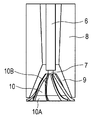
제1 관상 부재(6) 및 제2 관상 부재(7)는 원료 공급 유닛(8)에 제공되며, 압축 기체는 또한 각각의 관상 부재(6 및 7)에 공급된다. 제1 관상 부재(6)를 통과한 압축 기체는 제1 노즐(9) 및 제2 노즐(10) 사이에 형성된 공간을 통과한다. 제2 관상 부재(7)는 제2 노즐(10)을 관통하며, 압축 기체는 제2 노즐(10)의 내측에서 제2 관상 부재(7)의 출구부로부터 제2 노즐(10)의 내면을 향하여 분사된다. 복수의 리브(10B)는 제2 노즐(10)의 외주면의 위에 제공된다. 이들 리브(10B)는 하기 기재된 열풍 공급 유닛(2)으로부터 공급되는 열풍의 흐름 방향을 향하여 만곡된 방식으로 배열된다. 원료 공급 유닛(8)의 상류부로부터 제1 노즐(9)로 연장된 원료 공급로에서, 원료 공급 유닛(8)의 상류단의 직경보다 제1 노즐(9)에 연결된 원료 공급 유닛(8)의 부분의 직경이 더 작게 설계된다. 즉, 제2 노즐(10)은 제2 관상 부재(7)로의 연결부로부터 출구부의 방향으로 분기되도록 배열된다. 이는 공급된 토너 입자가 일단 제1 노즐(9)의 입구에서 유속이 가속되어 원료 토너의 분산을 추가로 보조할 수 있기 때문이다. 더욱이, 출구부 방향의 단부에서, 분기 각도는 추가로 변경되어 방사상 방향으로 연장되는 반환부(10A)를 형성한다.The first
도 2a 내지 도 2c에 도시된 열 처리 장치에서, 열풍 공급 유닛(2)은 원료 공급 유닛(8)의 외주면에 근접한 위치에서 또는 수평 방향으로 원료 공급 유닛(8)의 외주면으로부터 이격된 위치에서 방사상으로 제공된다. 더욱이, 열풍 공급 유닛(2)의 외측 및 하류측에는, 열 처리된 토너를 냉각시키고 그리고 장치내에서 온도 상승으로 인한 토너 입자의 합체 및 융착을 방지하기 위한 제1 냉풍 공급 유닛(3), 제2 냉풍 공급 유닛(4) 및 제3 냉풍 공급 유닛(5)이 배열된다. 열풍 공급 유닛(2)은 수평 방향으로 원료 공급 유닛(8)의 외주부로부터 이격된 위치에 방사상으로 제공될 수 있다. 이러한 경우에서, 제1 노즐(9) 및 제2 노즐(10)의 출구부는 제공된 열풍에 의하여 가열되고, 출구부로부터 분사된 토너 입자가 용융되어 서로 부착되는 현상을 방지할 수 있다.In the heat treatment apparatus shown in FIGS. 2A to 2C, the hot
도 3은 열풍 공급 유닛(2) 및 기류 조정부(2A)의 일례를 도시하는 부분 단면 개략도이다. 도 3에 도시된 바와 같이, 장치에 열풍을 공급하기 위한 기류 조정부(2A)는 경사 및 선회 방식으로 열풍 공급 유닛(2)의 출구부에 배열된다. 기류 조정부(2A)는 복수의 블레이드를 갖는 루버를 포함한다. 원통형 형상을 갖는 열풍 공급 유닛(2)으로부터 토너 처리 공간으로 공급된 열풍은 기류 조정부(2A)의 루버에 의하여 경사지며, 토너 처리 공간내에서 선회된다. 원료 공급 유닛(8)에 의하여 공급된 원료 토너는 열풍의 방향으로 선회된다. 원료 토너는 선회하면서 토너 처리 공간내에서 열 처리되어 열이 각각의 토너 입자에 실질적으로 균일하게 적용된다. 따라서, 샤프한 원형도 분포 및 샤프한 입도 분포를 갖는 토너 입자를 얻을 수 있다.3 is a partial cross-sectional schematic diagram showing an example of the hot
기류 조정부(2A)의 루버의 블레이드 개수 및 각도는 처리되는 원료의 유형 및 원료의 양에 따라 적절하게 조절될 수 있다. 기류 조정부(2A)에서 루버의 블레이드 각각의 경사각에 관하여, 수직 방향에 대한 각각의 블레이드의 주요면의 각도는 바람직하게는 20° 내지 70°, 더욱 바람직하게는 30° 내지 60°이다. 블레이드의 경사각이 상기 범위내에 포함될 경우, 열풍을 장치내에서 적절하게 선회시키면서 수직 방향으로의 풍속의 감소를 억제할 수 있다. 그 결과, 원료의 처리량이 증가하더라도, 토너 입자의 합체를 방지하며, 클리닝성에 불리하게 영향을 미치는, 원형도가 0.990 이상인 토너 입자의 형성 빈도도 또한 억제된다. 게다가, 장치 상부에서의 열이 체류하는 것을 방지하며, 이는 또한 제조 에너지면에서 효율적이다.The number and angle of the blades of the louver of the
열 처리 장치는 냉풍 공급 유닛을 포함할 수 있다. 도 4는 제1 냉풍 공급 유닛(3) 및 기류 조정부(3A)의 일례를 도시하는 부분 단면 개략도이다. 도 4에 도시한 바와 같이, 루버의 복수의 블레이드가 경사진 방식으로 소정 간격으로 배열된 기류 조정부(3A)는 냉풍이 장치내의 토너 처리 공간내에서 선회되도록 제1 냉풍 공급 유닛(3)의 출구부의 위에 배열된다. 기류 조정부(3A)의 루버의 경사는 상기 기재된 열풍 공급 유닛(2)으로부터 공급되는 열풍의 선회 방향과 실질적으로 동일한 방향(토너 처리 공간에서 원료 토너의 선회를 유지하는 방향)으로 에어가 선회하도록 조절된다. 이러한 구조는 열풍의 선회력을 추가로 증가시키며, 토너 처리 공간내의 온도의 증가를 억제하여 장치내의 외주부에서의 토너 입자의 융착 및, 토너 입자의 합체를 방지한다.The heat treatment apparatus may include a cold air supply unit. 4 is a partial cross-sectional schematic diagram showing an example of the first cold
제1 냉풍 공급 유닛(3)의 기류 조정부(3A)의 루버의 블레이드의 개수 및 각도는 또한 원료의 유형 및 원료의 처리량에 따라 적절하게 조절될 수 있다. 제1 냉풍 공급 유닛(3)에서 루버의 각각의 블레이드의 경사각과 관련하여, 수직 방향에 대한 각각의 블레이드의 주요면의 각도는 바람직하게는 20° 내지 70°, 더욱 바람직하게는 30° 내지 60°이다. 블레이드의 경사각이 상기 범위내에 포함되는 경우, 장치내의 토너 처리 공간에서의 열풍 및 토너 입자의 흐름은 방해받지 않으며, 장치의 상부에서의 열이 체류되는 것도 또한 방지된다.The number and angle of the blades of the louver of the
상기 기재된 냉풍 공급 유닛 이외에, 하나 이상의 냉풍 공급 유닛은 열풍 공급 유닛의 아래쪽에 제공되어 장치의 내부에 냉풍을 제공할 때 장치의 수직 방향으로 분할된 방식으로 공급된다. 예를 들면 각각의 제1 냉풍 공급 유닛(3), 제2 냉풍 공급 유닛(4) 및 제3 냉풍 공급 유닛(5)으로부터 토너 처리 공간으로 4개의 방향으로부터 분할된 방식으로 냉풍을 공급하도록 도 2a에 도시된 장치가 구성된다. 이러한 구조는 장치내에서 풍의 흐름을 균일하게 제어하기가 쉬운 것을 목적으로 한다. 4분할된 도입로에서의 냉풍의 풍량은 독립적으로 제어될 수 있다. 제2 냉풍 공급 유닛(4) 및 제3 냉풍 공급 유닛(5)은 제1 냉풍 공급 유닛(3)의 아래쪽에 배열될 수 있으며, 냉풍을 장치 외주부로부터 수평 및 접선 방향으로부터 공급하도록 구성될 수 있다.In addition to the cold air supply unit described above, one or more cold air supply units are provided below the hot air supply unit and are supplied in a divided manner in the vertical direction of the device when providing cold air to the inside of the device. 2a to supply, for example, cold air from each of the first cold
장치의 바닥면으로부터 제2 노즐(10) 부근까지 연장된 원통형 폴(14)은 장치의 축상 중심부에 제공된다. 냉풍은 또한 폴(14)에 도입되며, 냉풍은 폴(14)의 외주면으로부터 배출된다. 열풍 공급 유닛(2)으로부터 공급된 열풍 및 제1 냉풍 공급 유닛(3), 제2 냉풍 공급 유닛(4) 및 제3 냉풍 공급 유닛(5)로부터 공급된 냉풍의 선회 방향과 실질적으로 동일한 방향(토너 처리 공간내의 원료 토너의 선회가 유지되는 방향)으로 냉풍이 배출되도록 폴(14)의 출구부가 구성된다. 폴(14)의 출구부의 형상의 예로는 슬릿 형상, 루버 형상, 다공판 형상 및 메쉬 형상을 들 수 있다.A
더욱이, 토너 입자의 융착을 방지하기 위하여, 원료 공급 유닛(8)의 각각의 외주부, 장치의 외주부 및 열풍 공급 유닛(2)의 내주부 부근에 냉각 자켓이 제공된다. 부동액, 예컨대 냉각수 또는 에틸렌 글리콜을 냉각 자켓에 도입할 수 있다.Furthermore, in order to prevent fusion of the toner particles, a cooling jacket is provided in the vicinity of each outer peripheral portion of the raw
장치내에 공급된 열풍은 열풍 공급 유닛(2)의 출구부내에서의 온도 C(℃)가 100≤C≤450인 것이 바람직하다. 열풍 공급 유닛(2)의 출구부내에서의 열풍의 온도가 상기 범위내에 포함되는 경우, 구형화 처리는 과열로 인한 토너 입자의 융착 및 합체를 방지하면서 토너 입자의 입경 및 원형도가 실질적으로 균일하도록 실시될 수 있다.The hot air supplied into the apparatus preferably has a temperature C (° C) in the outlet of the hot
각각의 제1 냉풍 공급 유닛(3), 제2 냉풍 공급 유닛(4) 및 제3 냉풍 공급 유닛(5)내에서의 온도 E(℃)는 -20≤E≤40인 것이 바람직하다. 각각의 냉풍 공급 유닛내의 온도가 상기 범위내에 포함되는 경우, 토너 입자는 적절하게 냉각될 수 있으며, 토너 입자의 융착 및 합체가 방지될 수 있다.It is preferable that the temperature E (degreeC) in each 1st cold
냉각된 토너 입자는 토너 배출구(13)를 통과한 후, 회수된다. 송풍기(20)는 토너 배출구(13)의 하류측에 배열되며, 토너 입자는 송풍기(20)에 의하여 흡인 및 배출된다. 토너 배출구(13)는 장치의 외주부에 대하여 수평이 되도록 장치의 바닥면에 배열된다. 배출구(13)는 장치의 상류부로부터 배출구(13)로의 선회에 의하여 야기되는 흐름을 유지하는 방향으로 연결된다.The cooled toner particles are recovered after passing through the
열 처리 장치에서, 장치에 공급되는 압축 기체, 열풍 및 냉풍의 총 유량 QIN 및, 송풍기(20)에 의하여 흡인되는 기체의 풍량 QOUT은 QIN≤QOUT의 관계를 충족하도록 조절될 수 있는 것이 바람직하다. QIN≤QOUT의 관계가 충족될 경우, 장치내의 압력은 음압이 된다. 따라서, 분사된 토너 입자는 장치의 밖으로 쉽게 배출되어 토너 입자가 열을 지나치게 받지 않도록 한다. 그 결과, 합체된 분체 입자의 증가 및 장치내에서의 분체 입자의 융착을 방지할 수 있다.In the heat treatment apparatus, it is preferable that the total flow rates QIN of the compressed gas, the hot wind and the cold wind supplied to the apparatus, and the air volume QOUT of the gas sucked by the
본 발명의 토너는 1 성분 현상제로서 사용될 수 있다. 대안으로, 재현성을 추가로 개선시키지 않고 그리고 장시간 동안 안정한 화상을 얻기 위하여, 본 발명의 토너는 자성 캐리어와 혼합되어 2성분 현상제로서 사용될 수 있다. 토너와 조합하여 사용된 자성 캐리어는 진비중이 바람직하게는 3.2 g/㎤ 이상 4.9 g/㎤ 이하, 더욱 바람직하게는 3.4 g/㎤ 이상 4.2 g/㎤ 이하이다. 자성 캐리어의 진비중이 상기 범위내에 포함되는 경우, 현상기내의 현상제의 교반 중에 가해진 부하가 감소되며, 높은 인자 비율(인자 비율: 40% 이상)에서의 내구시 토너 소모는 억제된다. 더욱이, 토너의 마찰 대전량에서의 감소에 의하여 야기되는 비화상부에서의 포깅의 발생도 또한 억제된다.The toner of the present invention can be used as a one-component developer. Alternatively, the toner of the present invention can be used as a two-component developer in admixture with a magnetic carrier in order to obtain a stable image for a long time without further improving reproducibility. The magnetic carrier used in combination with the toner preferably has a specific gravity of 3.2 g /
본 발명의 토너와 조합하여 사용되는 자성 캐리어는 체적 분포 기준 50% 입경(D50)이 30.0㎛ 이상 70.0㎛ 이하인 것이 바람직하다. 자성 캐리어의 50% 입경 D50이 상기 범위내에 포함되는 경우, 토너의 대전량을 안정하게 얻는다. 본 발명의 토너와 조합하여 사용되는 자성 캐리어의 자화량에 관하여, 1,000 에르스테드의 자계하에서 측정한 자화의 강도(σ1000)는 현상성 및 내구중 안정성을 유지하는 면에서 15 A㎡/㎏(emu/g) 이상 65 A㎡/㎏(emu/g) 이하인 것이 바람직하다.The magnetic carrier used in combination with the toner of the present invention preferably has a volume distribution 50% particle size (D50) of 30.0 µm or more and 70.0 µm or less. When the 50% particle size D50 of the magnetic carrier falls within the above range, the charge amount of the toner is obtained stably. Regarding the magnetization amount of the magnetic carrier used in combination with the toner of the present invention, the intensity (? 1000) of magnetization measured under a magnetic field of 1,000 Ernst was 15
자성 캐리어의 예로는 금속, 예컨대 철, 리튬, 칼슘, 마그네슘, 니켈, 구리, 아연, 코발트, 망간, 크롬 또는 휘토류의 입자; 합금 입자 및 그의 산화물 입자; 자성체, 예컨대 페라이트; 및 자성체와, 자성체를 분산된 상태로 유지하는 결착 수지를 함유하는 자성체-분산된 수지 캐리어(이른바 수지 캐리어)를 들 수 있다.Examples of magnetic carriers include particles of metals such as iron, lithium, calcium, magnesium, nickel, copper, zinc, cobalt, manganese, chromium, or volatiles; Alloy particles and oxide particles thereof; Magnetic bodies such as ferrites; And a magnetic body-dispersed resin carrier (so-called resin carrier) containing a magnetic body and a binder resin which keeps the magnetic body in a dispersed state.
토너를 자성 캐리어와 혼합하고 그리고 2성분 현상제로서 사용되는 경우, 현상제 중의 토너 농도가 2 질량% 이상 15 질량% 이하, 바람직하게는 4 질량% 이상 13 질량% 이하인 경우 양호한 결과를 얻는다.When the toner is mixed with the magnetic carrier and used as a two-component developer, good results are obtained when the toner concentration in the developer is 2 mass% or more and 15 mass% or less, preferably 4 mass% or more and 13 mass% or less.
이제, 전자사진 장치에서의 화상 형성 방법을 기재할 것이다. 전자사진 감광 부재(상 담지 부재)는 소정 주변 속도로 선회 구동되고, 그의 표면은 선회 중 대전 디바이스에 의하여 양으로 또는 음으로 대전된다(대전 단계). 그후, 전자사진 감광 부재는 화상 노광 디바이스에 의하여 노광(예컨대 슬릿 노광 또는 레이저 비임 주사 노광)으로 처리한다. 따라서, 노광된 화상에 해당하는 정전 잠상은 감광 부재의 표면에 형성된다(잠상 형성 단계). 정전 잠상을 담지하는 전자사진 감광 부재에 대하여 현상 슬리브로부터 토너를 공급하여 토너 화상을 현상한다(현상 단계). 토너 화상을 전사 디바이스에 의하여 전사재에 전사시킨다(전사 단계). 토너 화상은 전사재에 직접 또는 중간 전사 부재를 통하여 전사시킬 수 있다. 전사재를 감광 부재의 표면으로부터 분리한 후, 화상 정착 디바이스로부터 공급된 열 및/또는 압력을 적용하여 토너 화상을 전사재에 정착시키고, 전사재를 복사물로서 장치의 외부로 출력한다. 화상의 전사후, 전자사진 감광 부재의 표면에서의 전사 잔여 토너를 클리닝 디바이스에 의하여 제거한다(클리닝 단계).Now, a method of forming an image in an electrophotographic apparatus will be described. The electrophotographic photosensitive member (image bearing member) is pivotally driven at a predetermined peripheral speed, and its surface is positively or negatively charged by the charging device during turning (charge step). Thereafter, the electrophotographic photosensitive member is subjected to exposure (eg, slit exposure or laser beam scanning exposure) by an image exposure device. Thus, an electrostatic latent image corresponding to the exposed image is formed on the surface of the photosensitive member (latent image forming step). The toner image is developed by supplying the toner from the developing sleeve to the electrophotographic photosensitive member carrying the electrostatic latent image (development step). The toner image is transferred to the transfer material by the transfer device (transfer step). The toner image can be transferred directly to the transfer material or through the intermediate transfer member. After separating the transfer material from the surface of the photosensitive member, the toner image is fixed to the transfer material by applying heat and / or pressure supplied from the image fixing device, and the transfer material is output to the outside of the apparatus as a copy. After the transfer of the image, the transfer residual toner on the surface of the electrophotographic photosensitive member is removed by a cleaning device (cleaning step).
본 발명의 토너는 블레이드 클리닝 단계를 비롯한 화상 형성 방법에 사용할 수 있으며, 클리닝은 블레이드를 상 담지 부재의 표면과 접촉시켜 실시한다. 예를 들면 평균 원형도가 크며 그리고 원형도가 0.990 이상인 토너 입자의 비율이 높은 토너, 예컨대 현탁 중합법에 의하여 얻은 토너 입자를 포함하는 토너를 사용하는 경우, 토너는 상 담지 부재 및 클리닝 블레이드 사이의 갭을 쉽게 통과하며, 그리하여 클리닝성이 양호하지 않다. 그러한 경우에서, 상 담지 부재 및 클리닝 블레이드 사이의 접촉 닙 부분의 평균 접촉 면압을 증가시키기 위하여 탄성 변형율이 큰 상 담지 부재를 사용하여 초기 클리닝성을 개선시킬 수 있다. 그러나, 내구후, 클리닝성은 블레이드의 진동으로 인하여 감소되는 경향을 갖는다.The toner of the present invention can be used in an image forming method including a blade cleaning step, and cleaning is performed by bringing the blade into contact with the surface of the image bearing member. For example, when using a toner having a high average circularity and having a high proportion of toner particles having a circularity of 0.990 or more, such as toners obtained by suspension polymerization, the toner is formed between the image bearing member and the cleaning blade. It easily passes through the gap, and thus the cleaning property is not good. In such a case, the initial cleaning property can be improved by using an image bearing member having a large elastic strain in order to increase the average contact surface pressure of the contact nip portion between the image bearing member and the cleaning blade. However, after durability, the cleaning property tends to be reduced due to the vibration of the blades.
반대로, 본 발명의 토너를 사용하는 경우, 원형도가 0.990 이상인 입자의 비율이 작기 때문에, 클리닝성은 양호하며, 탄성 변형율이 비교적 낮은 상 담지 부재를 사용할 수 있다. 일반적으로, 상 담지 부재의 탄성 변형율이 낮은 경우, 클리닝성은 감소되지만, 상 담지 부재의 내구성은 양호하다. 본 발명의 토너를 사용하는 경우, 탄성 변형율이 비교적 낮은 상 담지 부재를 사용할 수 있어서 장기간 동안 안정한 클리닝성을 얻을 수 있다. 더욱이, 본 발명의 토너는 공지의 분쇄법에 의하여 얻은 토너보다 평균 원형도가 더 높다. 그러므로, 본 발명의 토너는 클리닝성 이외에 전사성 및 현상성면에서 우수하다.On the contrary, when the toner of the present invention is used, since the proportion of particles having a roundness of 0.990 or more is small, an image bearing member having good cleaning property and relatively low elastic strain can be used. In general, when the elastic deformation rate of the image bearing member is low, the cleaning property is reduced, but the durability of the image bearing member is good. When using the toner of the present invention, an image bearing member having a relatively low elastic strain can be used, so that stable cleaning property can be obtained for a long time. Moreover, the toner of the present invention has a higher average circularity than the toner obtained by a known grinding method. Therefore, the toner of the present invention is excellent in terms of transferability and developability in addition to cleaning property.
상 담지 부재의 표면의 탄성 변형율은 40% 이상 70% 이하인 것이 바람직하다. 상 담지 부재 표면의 탄성 변형율이 상기 범위내에 포함되는 경우, 상 담지 부재의 표면은 쉽게 마모되지 않아서 내구성이 크다. 게다가, 클리닝 블레이드의 마찰 저항의 증가로 인한 클리닝 블레이드의 진동 및 클리닝 블레이드의 젖혀짐은 발생되지 않는 경향이 있다. 상 담지 부재 표면의 탄성 변형율은 45% 이상 60% 이하가 더욱 바람직하다.It is preferable that the elastic strain of the surface of an image bearing member is 40% or more and 70% or less. When the elastic deformation rate of the surface of the image bearing member falls within the above range, the surface of the image bearing member is not easily worn and thus has high durability. In addition, vibration of the cleaning blade and curling of the cleaning blade due to the increase in the frictional resistance of the cleaning blade tend not to occur. The elastic strain on the surface of the image bearing member is more preferably 45% or more and 60% or less.
클리닝 블레이드 및 감광 부재 사이의 접촉 면압은 10 gf/㎠ 이상 30 gf/㎠ 이하가 바람직하다. 상 담지 부재 위의 전사 잔여 토너가 클리닝 블레이드와의 갭을 쉽게 통과하지 못하도록 하기 위하여, 클리닝 블레이드 및 감광 부재 사이의 접촉 면압을 증가시키는 것이 바람직하다. 그러나, 클리닝 블레이드 및 상 담지 부재 사이의 압력이 지나치게 높을 경우, 내구시 특히 고온 고습 환경(온도: 32.5℃, 습도: 80% RH)에서, 클리닝 블레이드 표면 및 상 담지 부재 표면 사이의 마찰 저항은 증가되며, 클리닝 블레이드에는 지나친 부하가 가해진다. 지나친 부하가 클리닝 블레이드에 가해지는 경우, 클리닝 블레이드 선단의 치핑(chipping) 또는 클리닝 블레이드의 젖혀짐이 발생할 수 있으며, 선단의 치핑 또는 클리닝 블레이드의 젖혀짐으로 인하여 클리닝 불량이 야기될 수 있다. 이러한 현상은 클리닝 블레이드 및 전자사진 감광 부재 사이의 마찰 저항이 증가되기 때문에 전자사진 감광 부재 위의 최표면층의 물질의 마찰 계수 μ의 증가와 함께 크게 발생하는 경향이 있다.The contact surface pressure between the cleaning blade and the photosensitive member is preferably 10 gf /
상 담지 부재의 표면은 중합성 작용기를 갖는 화합물을 중합 또는 가교시켜 경화된 수지(이하, "경화성 수지"로 지칭할 수 있음)로 이루어질 수 있다. 그러한 경우에서, 상 담지 부재의 내구성은 추가로 개선된다. 가교 방법의 일례로는 상 담지 부재의 제조에 사용되는 코팅재에서 중합성 작용기를 갖는 단량체 또는 올리고머를 혼입하고, 코팅재를 적용하여 성막하고, 막을 건조시킨 후, 막을 가열 및 방사선 또는 전자선 조사의 적용에 의하여 막의 중합이 진행되도록 하는 방법을 들 수 있다.The surface of the image bearing member may be made of a resin cured by polymerizing or crosslinking a compound having a polymerizable functional group (hereinafter, referred to as "curable resin"). In such a case, the durability of the image bearing member is further improved. As an example of the crosslinking method, a monomer or oligomer having a polymerizable functional group is mixed in a coating material used for the manufacture of an image bearing member, a film is formed by applying a coating material, and the film is dried, and then the film is heated and applied to radiation or electron beam irradiation. The method of making superposition | polymerization of a film | membrane advance is mentioned.
클리닝 블레이드의 접촉 닙 부분의 평균 접촉 면압이 증가되더라도, 상기 상 담지 부재 및 본 발명의 토너의 조합에 의하여 클리닝 블레이드의 마찰 저항의 증가를 억제할 수 있다. 그 결과, 클리닝 블레이드의 진동 및 클리닝 블레이드의 젖혀짐은 억제될 수 있으며, 코로나 생성물(NOx 및 오존)은 대전 롤러 및 상 담지 부재 사이의 방전 전류에 의하여 긁어낼 수 있다. 따라서, 코로나 생성물로 인한 화상 결실을 억제할 수 있다.Even if the average contact surface pressure of the contact nip portion of the cleaning blade is increased, the increase in the frictional resistance of the cleaning blade can be suppressed by the combination of the image bearing member and the toner of the present invention. As a result, the vibration of the cleaning blade and the flipping of the cleaning blade can be suppressed, and the corona product (NO x and ozone) can be scraped off by the discharge current between the charging roller and the image bearing member. Thus, image deletion due to corona products can be suppressed.
경화성 수지를 함유하는 표면은 전하 수송 기능을 가질 수 있거나 또는 전하 수송 기능을 갖지 않을 수 있다. 경화성 수지를 함유하는 최표면층이 전하 수송 기능을 갖는 경우, 최표면층은 감광층의 일부로서 처리된다. 최표면층이 전하 수송 기능을 갖지 않는 경우, 최표면층은 하기 기재된 바와 같은 보호층(또는 표면 보호층)으로서 지칭되며, 감광층과는 구별된다.The surface containing the curable resin may have a charge transport function or may not have a charge transport function. When the outermost surface layer containing curable resin has a charge transport function, the outermost surface layer is treated as part of the photosensitive layer. If the outermost surface layer does not have a charge transport function, the outermost surface layer is referred to as a protective layer (or surface protective layer) as described below, and is distinguished from the photosensitive layer.
상 담지 부재의 감광층의 층 구조에 관하여, 전기 전도성 지지체측으로부터 전하 발생층 및 전하 수송층을 그 순서로 적층시킨 순적층 구조, 전기 전도성 지지체측으로부터 전하 수송층 및 전하 발생층을 그 순서로 적층시킨 역적층 구조 및, 전하 발생 물질 및 전하 수송 물질을 분산시킨 단층을 포함하는 구조 중 임의의 것을 사용할 수 있다.Regarding the layer structure of the photosensitive layer of the image bearing member, a net stacked structure in which the charge generating layer and the charge transport layer are laminated in this order from the electrically conductive support side, and the charge transport layer and the charge generating layer are laminated in that order from the electrically conductive support side. Any of a structure including a back stacked structure and a single layer in which the charge generating material and the charge transport material are dispersed can be used.
단일층으로 이루어진 감광층에서, 광캐리어의 생성 및 이동은 동일한 층내에서 실시되며, 감광층 자체는 표면층으로서 작용한다. 반대로, 적층된 층으로 이루어진 감광층은 광캐리어를 생성하는 전하 발생층 및 생성된 캐리어를 이동시키는 전하 수송층이 적층된 구조를 갖는다.In the photosensitive layer consisting of a single layer, the generation and movement of the photocarrier is carried out in the same layer, and the photosensitive layer itself acts as a surface layer. On the contrary, the photosensitive layer formed of the stacked layers has a structure in which a charge generating layer for generating a photocarrier and a charge transport layer for moving the generated carriers are stacked.
전기 전도성 지지체측으로부터 전하 발생층 및 전하 수송층이 그 순서로 적층되어 있는 순적층 구조가 가장 바람직하다.The net laminated structure in which the charge generation layer and the charge transport layer are laminated | stacked in the order from the electrically conductive support body side is the most preferable.
이러한 경우에서, 상 담지 부재는 경화성 수지를 함유하는 단층으로 이루어진 최표면층으로서 작용하는 전하 수송층을 포함할 수 있다. 대안으로, 상 담지 부재는 비-경화성 제1층 및, 최표면층으로 작용하는 경화성 제2층을 포함하는 적층된 층 구조를 갖는 전하 수송층을 포함할 수 있다. 이들 상 담지 부재 모두가 바람직하다.In such a case, the image bearing member may include a charge transport layer serving as an outermost layer consisting of a single layer containing a curable resin. Alternatively, the image bearing member may include a charge transport layer having a laminated layer structure including a non-curable first layer and a curable second layer serving as the outermost layer. All of these image bearing members are preferable.
단층 및 적층된 층 모두에서, 보호층은 감광층의 위에 제공될 수 있다. 이러한 경우에서, 보호층은 경화성 수지를 함유할 수 있다.In both monolayer and laminated layers, a protective layer can be provided over the photosensitive layer. In this case, the protective layer may contain curable resin.
본 발명의 토너 및 토너의 원료의 성질의 측정 방법은 하기 기재할 것이다.The measuring method of the toner of the present invention and the properties of the raw material of the toner will be described below.
토너의 평균 원형도, 원 상당 직경이 0.50㎛ 이상 1.98㎛ 미만인 입자 개수 비율 및, 원형도가 0.990 이상인 입자 개수 비율의 측정 방법Method of measuring the average circularity of the toner, the number of particles having a circle equivalent diameter of 0.50 µm or more and less than 1.98 µm, and the number of particles having a circularity of 0.990 or more
본 발명의 토너의 평균 원형도, 원 상당 직경이 0.50㎛ 이상 1.98㎛ 미만인 입자의 개수 비율 및, 원형도가 0.990 이상인 입자의 개수 비율은 플로우식 입자상 분석 장치 "FPIA-3000"(시스멕스 코포레이션(SYSMEX CORPORATION) 제조)으로 측정한다.The average circularity of the toner of the present invention, the number ratio of particles having a circle equivalent diameter of 0.50 µm or more and less than 1.98 µm, and the number ratio of particles having a circularity of 0.990 or more were calculated using the flow type particulate analyzer "FPIA-3000" (CISMEX CORPORATION ( SYSMEX CORPORATION).
구체적인 측정 방법은 하기와 같다. 우선, 고체 불순물 등이 미리 제거된 약 20㎖의 이온 교환수를 유리 용기에 넣는다. 분산제로서 "콘타미논(Contaminon) N"(비이온성 계면활성제, 음이온성 계면활성제 및 유기 빌더를 포함하며 그리고 pH가 7인 정밀 측정기 세정용 중성 세제 10 질량% 수용액, 와코 퓨어 케미칼 인코포레이티드(Wako Pure Chemical Industries, Ltd.) 제조)을 이온 교환수로 약 3 질량배로 희석하여 약 0.2㎖의 희석액을 제조하였다. 더욱이, 약 0.02 g의 측정 시료를 이에 첨가하고, 초음파 분산기를 사용하여 2 분 동안 분산 처리하여 측정용 분산액을 얻는다. 이 단계에서, 분산액의 온도가 10℃ 이상 40℃ 이하가 되도록 적절히 냉각을 실시한다. 진동 주파수 50 kHz 및 전기 출력 150 W의 탁상형 초음파 세정기 분산기(예를 들면 "VS-150"(벨보-클리어) 제조))를 분산기로서 사용하였다. 소정량의 이온 교환수를 장치의 수조에 넣고, 약 2㎖의 콘타미논 N을 수조에 첨가한다.The specific measuring method is as follows. First, about 20 ml of ion-exchange water in which solid impurities etc. were removed previously is put into a glass container. As a dispersant, "Contaminon N" (non-ionic surfactants, anionic surfactants and organic builders, 10% by mass aqueous detergent, Waco Pure Chemical Inc., for cleaning precision gauges with pH 7) (Manufactured by Wako Pure Chemical Industries, Ltd.) was diluted about 3 mass times with ion-exchanged water to prepare a diluent of about 0.2 ml. Furthermore, about 0.02 g of measurement sample is added thereto and dispersed for 2 minutes using an ultrasonic disperser to obtain a measurement dispersion. In this step, cooling is appropriately performed so that the temperature of the dispersion liquid is 10 ° C or more and 40 ° C or less. A table-top ultrasonic cleaner disperser (eg, "VS-150" (manufactured by Belvo-Clear)) with a vibration frequency of 50 kHz and an electrical output of 150 W was used as the disperser. A predetermined amount of ion exchanged water is placed in a water bath of the apparatus, and about 2 ml of contaminone N is added to the water bath.
측정의 경우, 표준 대물 렌즈(10배)가 장착된 상기 기재된 플로우식 입자상 분석기를 사용하였으며, 파티클 시쓰(PARTICLE SHEATH)(PSE-900A)(시스멕스 코포레이션 제조)를 시쓰액으로서 사용한다. 상기 기재된 절차에 의하여 제조된 분산액을 플로우식 입자상 분석기에 도입하고, HPF 측정 모드로 총 계수 모드에 의하여 3,000개의 토너 입자를 측정한다. 입자 분석시 2치화 역치를 85%로 설정하고, 입경 분석 범위를 명시한다. 그래서, 명시된 범위내의 입자의 개수 비율(%) 및 입자의 평균 원형도를 계산할 수 있다. 토너의 평균 원형도와 관련하여, 원 상당 직경 기준으로 입경의 분석 범위를 1.98㎛ 이상 200.00㎛ 미만으로 설정하고, 이러한 범위내의 토너의 평균 원형도를 구한다. 원형도가 0.990 이상 1.000 이하인 입자의 비율과 관련하여, 원 상당 직경 기준으로 입경 분석 범위는 1.98㎛ 이상 200.00㎛ 미만으로 설정하고, 입자의 개수 비율(%)은 상기 범위내에 포함되는 입자의 원형도 분포로부터 계산한다. 원 상당 직경이 0.50㎛ 이상 1.98㎛ 미만인 입자(소입자)의 비율과 관련하여, 원 상당 직경 기준으로 입경 분석 범위는 0.50㎛ 이상 1.98㎛ 미만으로 설정하고, 0.50㎛ 이상 200.00㎛ 미만의 범위에 포함되는 입자의 개수에 대한 0.50㎛ 이상 1.98㎛ 미만 범위에 포함되는 입자의 개수의 비(%)를 계산한다.For the measurement, the above-described flow particulate analyzer equipped with a standard objective lens (10 times) was used, and Particle Sheath (PSE-900A) (manufactured by Sysmex Corporation) was used as the seed liquid. The dispersion prepared by the procedure described above is introduced into a flow particulate analyzer, and 3,000 toner particles are measured by the total counting mode in the HPF measurement mode. In particle analysis, the binarization threshold is set to 85% and the particle size analysis range is specified. Thus, the percentage of the number of particles in the specified range and the average circularity of the particles can be calculated. Regarding the average circularity of the toner, the analysis range of the particle diameter is set to 1.98 µm or more and less than 200.00 µm on the basis of the circle equivalent diameter, and the average circularity of the toner within this range is obtained. Regarding the proportion of particles having a circularity of 0.990 or more and 1.000 or less, the particle size analysis range is set to 1.98 µm or more and less than 200.00 µm on the basis of the circle equivalent diameter, and the number ratio (%) of the particles falls within the above range. Count from the distribution. Regarding the proportion of particles (small particles) having a circle equivalent diameter of 0.50 μm or more and less than 1.98 μm, the particle size analysis range is set to 0.50 μm or more and less than 1.98 μm based on the circle equivalent diameter and included in the range of 0.50 μm or more and less than 200.00 μm. The ratio (%) of the number of particles contained in the range of 0.50 micrometers or more and less than 1.98 micrometers with respect to the number of particle | grains to become is calculated.
측정시에는 측정 개시 전 표준 라텍스 입자(예를 들면 듀크 사이언티픽 코포레이션(Duke Scientific Corporation)이 제조한 리서치 앤 테스트 파티클즈 라텍스 마이크로스피어 서스펜션즈(RESEARCH AND TEST PARTICLES Latex Microsphere Suspensions) 5200A를 이온 교환수로 희석하여 생성된 샘플)를 사용하여 자동 초점 조정을 실시한다. 그후, 측정 개시로부터 2시간마다 초점 조정을 실시할 수 있다.For measurement, use standard ion latex particles (such as RESEARCH AND TEST PARTICLES Latex Microsphere Suspensions 5200A manufactured by Duke Scientific Corporation) before ionization. Autofocus adjustment is carried out using a sample produced by dilution). Thereafter, focusing can be performed every two hours from the start of measurement.
본원의 실시예에서는 시스멕스 코포레이션에 의한 교정 작업을 실시하고 그리고 시스멕스 코포레이션이 발행한 교정 증명서를 접수한 플로우식 입자상 분석기를 사용하였다.In the Example of this application, the flow particle analyzer which performed the calibration operation by Sysmex Corporation and received the calibration certificate issued by Sysmex Corporation was used.
P1 및 P2의 계산 방법Calculation method of P1 and P2
FT-IR 스펙트럼은 유니버설 ATR 샘플링 악세서리가 구비된 푸리에 변환 적외선 분광광도계(스펙트럼 원(Spectrum One), 퍼킨엘머 인코포레이티드(PerkinElmer Inc.) 제조)를 사용하여 ATR 방법에 의하여 측정한다. P1, P2 및, P1을 P2로 나누어 구한 비[P1/P2]를 계산하기 위한 구체적인 측정 절차 및 방법은 하기와 같다.FT-IR spectra are measured by an ATR method using a Fourier transform infrared spectrophotometer (Spectrum One, manufactured by PerkinElmer Inc.) equipped with a universal ATR sampling accessory. Specific measurement procedures and methods for calculating P1, P2, and the ratio [P1 / P2] obtained by dividing P1 by P2 are as follows.
적외선광의 입사각은 45°로 설정한다. 게르마늄(Ge) ATR 결정(굴절율=4.0) 및 KRS5 ATR 결정(굴절율=2.4)을 ATR 결정으로서 사용한다. 기타 조건은 하기와 같다:The incident angle of infrared light is set to 45 degrees. Germanium (Ge) ATR crystals (refractive index = 4.0) and KRS5 ATR crystals (refractive index = 2.4) are used as ATR crystals. Other conditions are as follows:
범위range
시작: 4,000 ㎝-1 Start: 4,000 cm -1
종료: 600 ㎝-1(Ge ATR 결정)Finish: 600 cm -1 (Ge ATR Crystals)
400 ㎝-1(KRS5 ATR 결정)400 cm -1 (KRS5 ATR crystal)
기간term
주사 수: 16Injection Number: 16
해상도: 4.00 ㎝-1 Resolution: 4.00 cm -1
Advanced: CO2/H2O 보정을 실시함Advanced: Performs CO 2 / H 2 O calibration
P1의 계산 방법Calculation method of P1
(1) Ge ATR 결정(굴절율=4.0)을 분광광도계에 장착한다.(1) A Ge ATR crystal (refractive index = 4.0) is attached to the spectrophotometer.
(2) "스캔 타입"을 "배경"으로 설정하고, "단위"는 "EGY"로 설정한다. 배경은 이들 조건하에서 측정한다.(2) Set "Scan Type" to "Background" and "Unit" to "EGY". Background is measured under these conditions.
(3) "스캔 타입"은 "샘플"로 설정하고, "단위"는 "A"로 설정한다.(3) "Scan type" is set to "sample", and "unit" is set to "A".
(4) 0.01 g의 토너를 정확하게 평량하고, ATR 결정의 위에 놓는다.(4) 0.01 g of toner is accurately weighed and placed on top of the ATR crystal.
(5) 가압 아암으로 샘플에 가압한다("힘 게이지"는 90으로 설정한다).(5) Pressurize the sample with the pressure arm ("force gauge" is set to 90).
(6) 샘플의 측정을 수행한다.(6) Measure the sample.
(7) 얻은 FT-IR 스펙트럼은 "자동 보정"에서 기준선 보정으로 처리한다.(7) The obtained FT-IR spectrum is treated as baseline correction in "Auto Correction".
(8) 2,843 ㎝-1 이상 2,853 ㎝-1 이하 범위내의 흡수 피크 강도의 최대값을 계산한다(Pa1).(8) The maximum value of the absorption peak intensity within the range of 2,843 cm -1 or more and 2,853 cm -1 or less is calculated (Pa1).
(9) 3,050 ㎝-1에서의 흡수 강도 및 2,600 ㎝-1에서의 흡수 강도의 평균값을 계산한다(Pa2).(9) The average value of the absorption strength at 3,050 cm -1 and the absorption strength at 2,600 cm -1 is calculated (Pa2).
(10) Pa1로부터 Pa2를 빼어 계산한 값은 Pa로 정의한다(Pa1-Pa2=Pa). 이 값 Pa는 2,843 ㎝-1 이상 2,853 ㎝-1 이하 범위내의 최대 흡수 피크 강도로 정의한다.(10) The value calculated by subtracting Pa2 from Pa1 is defined as Pa (Pa1-Pa2 = Pa). This value Pa is defined as the maximum absorption peak intensity within the range of 2,843 cm -1 or more and 2,853 cm -1 or less.
(11) 1,713 ㎝-1 이상 1,723 ㎝-1 이하 범위내의 흡수 피크 강도의 최대값을 계산한다(Pb1).(11) The maximum value of the absorption peak intensity within the range of 1,713 cm -1 or more and 1,723 cm -1 or less is calculated (Pb1).
(12) 1,763 ㎝-1에서의 흡수 강도 및 1,630 ㎝-1에서의 흡수 강도의 평균값을 계산한다(Pb2).(12) The average value of the absorption strength at 1,763 cm -1 and the absorption strength at 1,630 cm -1 is calculated (Pb2).
(13) Pb1로부터 Pb2를 빼어 계산한 값은 Pb로 정의한다(Pb1-Pb2=Pb). 이 값 Pb는 1,713 ㎝-1 이상 1,723 ㎝-1 이하 범위내의 최대 흡수 피크 강도로서 정의한다.(13) The value calculated by subtracting Pb2 from Pb1 is defined as Pb (Pb1-Pb2 = Pb). This value Pb is defined as the maximum absorption peak intensity in the range of 1,713 cm -1 or more and 1,723 cm -1 or less.
(14) Pa를 Pb로 나누어 계산한 값을 P1로서 정의한다(Pa/Pb=P1).(14) The value calculated by dividing Pa by Pb is defined as P1 (Pa / Pb = P1).
P2의 계산 방법Calculation method of P2
(1) KRS5 ATR 결정(굴절율=2.4)을 분광광도계에 장착한다.(1) Mount KRS5 ATR crystal (refractive index = 2.4) on the spectrophotometer.
(2) 0.01 g의 토너를 정확하게 평량하고, ATR 결정의 위에 놓는다.(2) 0.01 g of toner is accurately weighed and placed on top of the ATR crystal.
(3) 가압 아암으로 샘플에 가압한다("힘 게이지"는 90으로 설정한다).(3) Pressurize the sample with the pressure arm ("force gauge" is set to 90).
(4) 샘플의 측정을 수행한다.(4) Perform measurement of the sample.
(5) 얻은 FT-IR 스펙트럼은 "자동 보정"에서 기준선 보정으로 처리한다.(5) The obtained FT-IR spectrum is treated as baseline correction in "auto correction".
(6) 2,843 ㎝-1 이상 2,853 ㎝-1 이하 범위내의 흡수 피크 강도의 최대값을 계산한다(Pc1).(6) The maximum value of the absorption peak intensity within the range of 2,843 cm -1 or more and 2,853 cm -1 or less is calculated (Pc1).
(7) 3,050 ㎝-1에서의 흡수 강도 및 2,600 ㎝-1에서의 흡수 강도의 평균값을 계산한다(Pc2).(7) The average value of the absorption strength at 3,050 cm -1 and the absorption strength at 2,600 cm -1 is calculated (Pc2).
(8) Pc1로부터 Pc2를 빼어 계산한 값은 Pc로 정의한다(Pc1-Pc2=Pc). 이 값 Pc는 2,843 ㎝-1 이상 2,853 ㎝-1 이하 범위내의 최대 흡수 피크 강도로 정의한다.(8) The value calculated by subtracting Pc2 from Pc1 is defined as Pc (Pc1-Pc2 = Pc). This value Pc is defined as the maximum absorption peak intensity within the range of 2,843 cm -1 or more and 2,853 cm -1 or less.
(9) 1,713 ㎝-1 이상 1,723 ㎝-1 이하 범위내의 흡수 피크 강도의 최대값을 계산한다(Pd1).(9) The maximum value of the absorption peak intensity within the range of 1,713 cm -1 or more and 1,723 cm -1 or less is calculated (Pd1).
(10) 1,763 ㎝-1에서의 흡수 강도 및 1,630 ㎝-1에서의 흡수 강도의 평균값을 계산한다(Pd2).(10) The average value of the absorption strength at 1,763 cm -1 and the absorption strength at 1,630 cm -1 is calculated (Pd2).
(11) Pd1로부터 Pd2를 빼어 계산한 값은 Pd로 정의한다(Pd1-Pd2=Pd). 이 값 Pd는 1,713 ㎝-1 이상 1,723 ㎝-1 이하 범위내의 최대 흡수 피크 강도로서 정의한다.(11) The value calculated by subtracting Pd2 from Pd1 is defined as Pd (Pd1-Pd2 = Pd). This value Pd is defined as the maximum absorption peak intensity within the range of 1,713 cm -1 or more and 1,723 cm -1 or less.
(12) Pc를 Pd로 나누어 계산한 값을 P2로서 정의한다(Pc/Pd=P2).(12) The value calculated by dividing Pc by Pd is defined as P2 (Pc / Pd = P2).
P1/P2의 계산Calculation of P1 / P2
비 P1/P2는 상기 기재된 바와 같이 측정한 P1 및 P2를 사용하여 계산한다.The ratio P1 / P2 is calculated using P1 and P2 measured as described above.
수지의 중량-평균 분자량(Mw) 및 피크 분자량(Mp)의 측정 방법Method for measuring weight-average molecular weight (Mw) and peak molecular weight (Mp) of resin
수지의 중량-평균 분자량(Mw) 및 피크 분자량(Mp)은 하기와 같은 겔 투과 크로마토그래피(GPC)에 의하여 측정한다.The weight-average molecular weight (Mw) and peak molecular weight (Mp) of the resin are measured by gel permeation chromatography (GPC) as follows.
우선, 샘플(수지)을 테트라히드로푸란(THF) 중에 실온에서 24 시간에 걸쳐 용해시킨다. 그후, 생성된 용액을 공극 직경이 0.2㎛인 내용제성 멤브레인 필터 마이쇼리 디스크(MAISHORI Disk)(도소 코포레이션(Tosoh Corporation) 제조)로 여과하여 샘플 용액을 제조한다. THF 중의 가용성 성분의 농도가 약 0.8 질량%가 되도록 샘플 용액을 조절한다. 이러한 샘플 용액을 사용하여 하기 조건하에서 측정을 실시한다:First, the sample (resin) is dissolved in tetrahydrofuran (THF) at room temperature over 24 hours. The resulting solution is then filtered through a solvent resistant membrane filter MAISHORI Disk (manufactured by Tosoh Corporation) having a pore diameter of 0.2 mu m to prepare a sample solution. The sample solution is adjusted so that the concentration of soluble components in THF is about 0.8 mass%. Using this sample solution the measurements are carried out under the following conditions:
장치: HLC8120 GPC(검출기: RI)(도소 코포레이션 제조)Device: HLC8120 GPC (detector: RI) (manufactured by Tosoh Corporation)
컬럼: 쇼덱스(Shodex) KF-801, 802, 803, 804, 805, 806 및 807(쇼와 덴코 가부시키가이샤(SHOWA DENKO K.K.) 제조)인 7개의 컬럼의 조합Column: Combination of seven columns, Shodex KF-801, 802, 803, 804, 805, 806 and 807 (manufactured by SHOWA DENKO K.K.)
용리액: THFEluent: THF
유속: 1.0㎖/min.Flow rate: 1.0 ml / min.
오븐 온도: 40.0℃Oven temperature: 40.0 캜
시료 주입량: 0.10㎖Sample injection volume: 0.10 ml
샘플의 분자량 계산에서, 표준 폴리스티렌 수지(예를 들면 상표명 TSK 스탠다드 폴리스티렌(Standard Polystyrene) F-850, F-450, F-288, F-128, F-80, F-40, F-20, F-10, F-4, F-2, F-1, A-5000, A-2500, A-1000 및 A-500, 도소 코포레이션 제조)를 사용하여 작성한 분자량 교정 곡선을 사용한다.In calculating the molecular weight of a sample, a standard polystyrene resin (e.g. trade name TSK Standard Polystyrene F-850, F-450, F-288, F-128, F-80, F-40, F-20, F A molecular weight calibration curve created using -10, F-4, F-2, F-1, A-5000, A-2500, A-1000 and A-500, manufactured by Tosoh Corporation) is used.
왁스의 최대 흡열 피크의 측정Determination of the maximum endothermic peak of the wax
왁스의 최대 흡열 피크는 ASTM D3418-82에 의하여 시차 주사 열량계 Q1000(티에이 인스트루먼츠(TA Instruments) 제조)를 사용하여 측정한다. 장치의 검출부의 온도 보정은 인듐 및 아연의 융점을 사용하여 실시하며, 열량의 보정은 인듐의 융해열을 사용하여 실시한다.The maximum endothermic peak of the wax is measured using a differential scanning calorimeter Q1000 (manufactured by TA Instruments) by ASTM D3418-82. The temperature correction of the detection part of the device is carried out using melting points of indium and zinc, and the correction of calories is carried out using heat of fusion of indium.
왁스의 최대 흡열 피크는 하기와 같이 구체적으로 측정한다.The maximum endothermic peak of the wax is specifically measured as follows.
약 5 ㎎의 왁스를 정확하게 평량하고, 알루미늄 팬에 넣는다. 비어 있는 알루미늄 팬을 기준으로 사용한다. 측정은 30℃ 내지 200℃의 측정 온도 범위에서 그리고 10℃/min의 승온 속도로 측정을 실시한다. 측정시, 온도를 일단 200℃로 승온시킨 후, 30℃로 감온시킨다. 그후, 온도를 다시 승온시킨다. 이러한 제2 승온 과정에서 30℃ 내지 200℃의 온도 범위내에서의 DSC 곡선의 최대 흡열 피크는 왁스의 DSC 측정에서 흡열 곡선의 최대 흡열 피크로서 정의한다.Accurately weigh about 5 mg of wax and place in an aluminum pan. Use an empty aluminum pan as a reference. The measurement is carried out in the measurement temperature range of 30 ° C to 200 ° C and at a temperature rising rate of 10 ° C / min. In the measurement, the temperature is once raised to 200 ° C, and then reduced to 30 ° C. The temperature is then raised again. The maximum endothermic peak of the DSC curve in the temperature range of 30 ° C. to 200 ° C. in this second elevated temperature process is defined as the maximum endothermic peak of the endothermic curve in the DSC measurement of the wax.
중량-평균 입경(D4) 및 수-평균 입경(D1)의 측정 방법Measurement method of weight-average particle diameter (D4) and number-average particle diameter (D1)
토너의 중량-평균 입경(D4) 및 수-평균 입경(D1)은 하기 기재한 바와 같으 계산한다. 세공 전기 저항법을 사용하며 그리고 100㎛ 어퍼쳐(aperture) 튜브를 구비한 정밀 입도 분포 분석기 "쿨터 카운터 멀티사이저(Coulter Counter Multisizer) 3"(등록상표, 벡맨 쿨터, 인코포레이티드(Beckman Coulter, Inc.) 제조)를 측정 장치로서 사용한다. 측정 조건의 설정 및 측정 데이타의 분석에 관하여, 부속 전용 소프트웨어 "벡맨 쿨터 멀티사이저 3 버젼 3.51(Beckman Coulter Multisizer 3 Version 3.51)"(벡맨 쿨터, 인코포레이티드 제조)를 사용한다. 측정은 실효 측정 채널수 25,000개의 채널로 실시한다.The weight-average particle diameter (D4) and the number-average particle diameter (D1) of the toner are calculated as described below. Precision particle size distribution analyzer "
측정에 사용되는 전해 수용액으로서, 분석 등급의 염화나트륨을 이온 교환수에 용해시켜 농도가 약 1 질량%가 되도록 하여 제조된 용액, 예를 들면 "이소톤(ISOTON) II"(벡맨 쿨터, 인코포레이티드 제조)를 사용할 수 있다.As an electrolytic aqueous solution used for the measurement, a solution prepared by dissolving analytical grade sodium chloride in ion-exchanged water to a concentration of about 1% by mass, for example, "ISOTON II" (Beckman Coulter, Inc.) Tied production) can be used.
측정 및 분석전, 전용 소프트웨어를 하기 기재한 바와 같이 설정한다.Prior to measurement and analysis, dedicated software is set up as described below.
전용 소프트웨어의 "표준 작동 방법(SOM)의 변경"의 스크린에서, 콘트롤 모드에서의 총 카운트수를 50,000 입자로 설정하고, 측정 횟수는 1회로 설정하고, Kd값은 "표준 입자 10.0㎛"(벡맨 쿨터, 인코포레이티드 제조)를 사용하여 얻은 값으로 설정한다. 역치 및 노이즈 레벨은 "역치/노이즈 레벨 측정 버튼"을 눌러 자동 설정한다. 전류는 1,600 ㎂로 설정하고, 이득은 2로 설정하고, 전해액은 이소톤 II로 설정하고, "측정후 실시된 어퍼쳐 튜브 플러쉬"에 체크 마크를 기입한다.On the screen of "Change of Standard Operating Method (SOM)" of the dedicated software, set the total count in the control mode to 50,000 particles, set the number of measurements to one time, and set the Kd value to "standard particle 10.0 µm" (Beckman). Coulter, manufactured by Co., Ltd.). The threshold and noise level are set automatically by pressing the "Threshold / noise level measurement button". The current is set to 1,600 mA, the gain is set to 2, the electrolyte is set to Isotone II, and a check mark is written in "aperture tube flush performed after measurement".
전용 소프트웨어의 "펄스로부터 입경으로의 전환 설정"의 스크린에서, 빈(bin) 간격을 대수 입경으로 설정하고, 입경 빈은 256 입경 빈으로 설정하고, 입경 범위는 2㎛ 내지 60㎛로 설정한다.On the screen of "Pulse to Particle Size Setting" of the dedicated software, the bin interval is set to the logarithmic particle size, the particle size bin is set to 256 particle size bins, and the particle size range is set to 2 µm to 60 µm.
구체적인 측정 방법은 하기 기재한 바와 같다.Specific measurement methods are as described below.
(1) 약 200㎖의 상기 전해 수용액을 멀티사이저 3의 전용 250㎖ 둥근 바닥 유리 비이커에 넣고, 비이커를 샘플 스탠드에 세팅한다. 교반기 로드를 사용하여 24 회전/sec로 시계 반대 방향 교반을 실시한다. 그후, 전용 소프트웨어의 "어퍼쳐 플러쉬"에 의하여 어퍼쳐 튜브내의 오염 및 기포를 제거한다.(1) Approximately 200 ml of the electrolytic solution was placed in a dedicated 250 ml round bottom glass beaker of
(2) 약 30㎖의 전해 수용액을 100㎖ 평편 바닥 유리 플라스크에 넣는다. "콘타미논 N"(비이온성 계면활성제, 음이온성 계면활성제 및 유기 빌더를 포함하며 pH가 7인 정밀 측정기 세정용 중성 세제의 10 질량% 수용액, 와코 퓨어 케미칼 인더스트리즈 제조)을 이온교환수로 질량 기준으로 약 3 질량부로 희석하여 제조한 약 0.3㎖의 희석액을 전해 수용액에 첨가한다.(2) Put about 30 ml of the electrolytic solution into a 100 ml flat bottom glass flask. "Contaminone N" (10% by mass aqueous solution of a neutral detergent for cleaning precision measuring instruments with a pH of 7, including nonionic surfactants, anionic surfactants and organic builders, manufactured by Wako Pure Chemical Industries) as ion exchange water About 0.3 ml of the diluted solution prepared by diluting to about 3 parts by mass on a mass basis is added to the electrolytic aqueous solution.
(3) 위상이 180°로 변위되도록 진동 주파수 50 kHz의 진동기 2개를 내장하고, 전기 출력이 120 W인 초음파 분산기인 "울트라소닉 디스퍼젼 시스템 테토라 150(Ultrasonic Dispersion System Tetora 150)"(니카키 바이오스 컴파니, 리미티드 제조)을 준비한다. 그후, 약 3.3ℓ의 이온교환수를 초음파 분산기의 수조에 넣고, 약 2㎖의 콘타미논 N을 수조에 첨가한다.(3) Ultrasonic Dispersion System Tetora 150, an ultrasonic disperser with a vibrational frequency of 50 kHz with two vibration frequencies of 50 kHz with a phase shift of 180 °. Khaki Bios Co., Ltd.). Thereafter, about 3.3 L of ion-exchanged water is placed in a water bath of the ultrasonic disperser, and about 2 ml of contaminone N is added to the water bath.
(4) 상기 (2)의 비이커를 초음파 분산기의 비이커 고정 구멍에 장착하고, 초음파 분산기를 작동시킨다. 그래서, 비이커내의 전해 수용액의 액면의 공진 상태가 최대가 되도록 비이커의 높이 위치를 조절한다.(4) The beaker of (2) is mounted in the beaker fixing hole of the ultrasonic dispersion machine, and the ultrasonic dispersion machine is operated. Thus, the height position of the beaker is adjusted so that the resonance state of the liquid level of the electrolytic aqueous solution in the beaker is maximized.
(5) 상기 (4)의 비이커내의 전해 수용액에 초음파를 가하면서, 약 10 ㎎의 토너를 조금씩 전해 수용액에 첨가하고, 분산시킨다. 그후, 초음파 분산 처리를 추가로 60 초 동안 지속한다. 초음파 분산 중에 수조의 수온을 10℃ 이상 40℃ 이하가 되도록 적절하게 조절한다.(5) While applying ultrasonic waves to the electrolytic aqueous solution in the beaker of (4), about 10 mg of the toner was added little by little to the electrolytic aqueous solution and dispersed. Thereafter, the ultrasonic dispersion treatment is continued for an additional 60 seconds. The water temperature of the water tank is suitably adjusted so that it may become 10 degreeC or more and 40 degrees C or less during ultrasonic dispersion.
(6) 샘플 스탠드에 장착한 (1)의 둥근 바닥 비이커에 피펫을 사용하여 상기 (5)의 토너가 분산된 전해 수용액을 적하하고, 측정 농도가 약 5%가 되도록 조절한다. 그후, 측정된 입자의 수가 50,000이 될 때까지 측정을 실시한다.(6) The electrolytic aqueous solution in which the toner of said (5) was disperse | distributed was dripped at the round bottom beaker of (1) attached to the sample stand, and it adjusted so that a measurement density might be about 5%. Thereafter, the measurement is carried out until the number of particles measured is 50,000.
(7) 측정 데이타를 장치에 부착된 전용 소프트웨어로 분석하고, 중량-평균 입경(D4) 및 수-평균 입경(D1)을 계산한다. 이러한 분석에서, 그래프/부피%를 전용 소프트웨어로 설정시 "분석/부피 통계치(산술 평균)"의 스크린에서의 "평균 직경"은 중량 평균 입경(D4)이다. "그래프/개수%"는 전용 소프트웨어로 설정할 때, "분석/개수 통계치(산술 평균)"의 스크린에서의 "평균 직경"은 수-평균 입경(D1)이다.(7) The measurement data is analyzed by dedicated software attached to the apparatus, and the weight-average particle diameter (D4) and the number-average particle diameter (D1) are calculated. In this analysis, the "average diameter" on the screen of "analysis / volume statistics (arithmetic mean)" when the graph / volume% is set with dedicated software is the weight average particle diameter (D4). When "Graph / Number%" is set with dedicated software, the "average diameter" on the screen of "Analysis / Number Statistics (arithmetic mean)" is the number-average particle diameter (D1).
미립자(4.0㎛ 이하의 입자) 양의 계산 방법Method of calculating the amount of fine particles (particles of 4.0 μm or less)
토너 중의 개수 기준의 미립자(직경이 4.0㎛ 이하인 입자)의 양(개수%)은 상기 기재된 멀티사이저 3을 사용한 측정을 실시한 후, 데이타를 분석하여 계산한다.The amount (number%) of the fine particles (particles having a diameter of 4.0 μm or less) based on the number in the toner is calculated by analyzing the data after performing the measurement using the
토너의 개수 기준으로 직경이 4.0㎛ 이하인 입자의 비율은 하기 절차에 의하여 계산한다. 우선, 전용 소프트웨어에서, "그래프/개수%"로 설정하여 측정 결과의 차트를 개수%로 표시한다. 그후, "포맷/입경/입경 통계" 스크린에 입경-설정부의 "<"에 체크 마크를 기입하고, 입경-설정부 아래의 입경 입력부에 "4"를 입력한다. "분석/개수 통계값(산술 평균)"의 스크린에서 "<4㎛" 표시부의 수치는 토너 중의 개수 기준으로 직경이 4.0㎛ 이하인 입자의 비율이다.The proportion of particles having a diameter of 4.0 μm or less based on the number of toners is calculated by the following procedure. First, in the dedicated software, set "Graph / Number" to display the chart of the measurement results in number%. Thereafter, a check mark is written in " <" of the particle size-setting section on the "Format / particle size / particle size statistics" screen, and " 4 " On the screen of the "Analysis / Count Statistical Value (arithmetic mean)", the numerical value of the "<4 micrometer" display part is the ratio of the particle | grains whose diameter is 4.0 micrometers or less with respect to the number in a toner.
조립자(10.0㎛ 이상의 입자) 양의 계산 방법Calculation method of granules (particles of 10.0 μm or more)
토너 중 부피 기준으로 조립자(직경이 10.0㎛ 이상인 입자)의 양(부피%)은 상기 기재된 멀티사이저 3을 사용한 측정후 데이타를 분석하여 계산한다. 토너 중의 부피 기준으로 직경이 10.0㎛ 이상인 입자의 비율은 하기 절차에 의하여 계산한다. 우선, 전용 소프트웨어에서, 측정 결과의 차트는 부피%의 단위로 나타내도록 "그래프/부피%"로 설정한다. 그 다음, "포맷/입경/입경 통계"의 스크린에서 입경-설정부의 ">"에 체크 마크를 기입하고, "10"을 입경-설정부 아래의 입경-입력부에 입력한다. "분석/부피 통계치(산술 평균)"의 스크린에서 "> 10㎛"의 표시부의 수치는 토너 중의 부피 기준으로 직경이 10.0㎛ 이상인 입자의 비율이다.The amount (vol%) of coarse particles (particles having a diameter of 10.0 μm or more) based on the volume in the toner is calculated by analyzing the data after the measurement using the
자성 캐리어 및 자성 캐리어 코어 물질의 자화 강도 측정 방법Method of measuring magnetization strength of magnetic carrier and magnetic carrier core material
자성 캐리어 및 자성 캐리어 코어 물질의 자화 강도는 진동 자기장 타입 자기 특성 측정 장치(진동 샘플 자력계) 또는 직류 자화 특성 기록 장치(B-H 트레이서)로 구할 수 있다. 본원의 실시예에서, 진동 자기장 타입 자기 특성 측정 장치 BHV-30(리켄 덴시 컴파니, 리미티드(Riken Denshi Co., Ltd.) 제조)를 사용하여 하기 절차에 의하여 측정을 실시한다.The magnetization strength of the magnetic carrier and the magnetic carrier core material can be obtained with a vibrating magnetic field type magnetic property measuring device (vibrating sample magnetometer) or a direct current magnetization property recording device (B-H tracer). In the examples herein, the measurement is carried out using the vibration magnetic field type magnetic property measuring device BHV-30 (manufactured by Riken Denshi Co., Ltd.) by the following procedure.
(1) 캐리어가 충분히 조밀하게 충전된 원통형 플라스틱 용기를 샘플로서 사용한다. 캐리어가 충전된 용기의 실제 질량을 측정한다. 그후, 플라스틱 용기내의 자성 캐리어 입자를 순간 접착제로 접합시켜 자성 캐리어 입자가 이동하지 않게 한다.(1) A cylindrical plastic container filled with sufficient density of carriers is used as a sample. Measure the actual mass of the container filled with the carrier. Thereafter, the magnetic carrier particles in the plastic container are bonded with the instant adhesive so that the magnetic carrier particles do not move.
(2) 5,000/4π(kA/m)에서 외부 자기장 축 및 자화 모멘트 축을 표준 샘플을 사용하여 교정한다.(2) Calibrate the external magnetic field axis and magnetization moment axis at 5,000 / 4π (kA / m) using a standard sample.
(3) 스위프 속도를 5 min/루프로 설정할 때 얻은 자화 모멘트의 루프로부터 자화 강도를 측정하고, 1,000/4π(kA/m)의 외부 자기장을 인가한다. 이러한 결과를 토대로 하여, 자화 강도를 샘플 질량으로 나누어 캐리어의 자화 강도(A㎡/㎏)를 구한다.(3) The magnetization strength is measured from the loop of the magnetization moment obtained when the sweep speed is set to 5 min / loop, and an external magnetic field of 1,000 / 4π (kA / m) is applied. Based on these results, the magnetization strength is divided by the sample mass to obtain the magnetization strength (
자성 캐리어의 부피 분포 기준 50% 입경(D50)의 측정 방법Measurement method of 50% particle size (D50) based on the volume distribution of the magnetic carrier
레이저 회절/산란 입도 분포 분석기 마이크로트랙(Microtrac) MT3300EX(니키소 컴파니, 리미티드(NIKKISO CO., LTD.) 제조)을 사용하여 입도 분포를 측정한다. 건식 측정용 샘플 공급기, 즉 원-샷 드라이-타입 샘플 컨디셔너 터보트랙(Turbotrac)(니키소 컴파니, 리미티드 제조)을 부착하여 측정을 실시한다. 터보트랙의 공급 조건에 관하여, 더스트 회수기를 진공 공급원으로서 사용하고, 에어 유속은 약 33ℓ/sec로 설정하고, 압력은 약 17 kPa로 설정한다. 제어는 소프트웨어에 의하여 자동 실행한다. 부피 기준으로 누적값인 50% 입경(D50)을 입경으로서 구한다. 제어 및 분석은 부착된 소프트웨어(버젼 10.3.3-202D)를 사용하여 실시한다.The particle size distribution is measured using a laser diffraction / scattering particle size distribution analyzer Microtrac MT3300EX (manufactured by Nikkiso Co., Ltd.). The measurement is carried out by attaching a dry feed sample feeder, ie a one-shot dry-type sample conditioner, Turbobotrac (Nikeso Company, Limited). Regarding the supply conditions of the turbotrack, the dust recovery machine is used as the vacuum source, the air flow rate is set to about 33 L / sec, and the pressure is set to about 17 kPa. Control is performed automatically by software. The 50% particle size (D50), which is a cumulative value on a volume basis, is obtained as the particle size. Control and analysis are performed using the attached software (version 10.3.3-202D).
측정 조건은 하기와 같다:The measurement conditions are as follows:
0 시간 설정: 10 초0 time setting: 10 seconds
측정 시간: 10 초Measurement time: 10 seconds
측정 횟수: 1회Number of measurements: 1
입자 굴절율: 1.81Particle Refractive Index: 1.81
입자 형상: 비-구체 형상Particle Geometry: Non-Spherical Geometry
측정 상한: 1,408㎛Upper limit of measurement: 1,408 µm
측정 하한: 0.243㎛Lower limit of measurement: 0.243 μm
측정 환경: 실온 및 정상 습도 환경(23℃ 50% RH)Measurement environment: room temperature and normal humidity environment (23 ° C 50% RH)
자성 캐리어의 진비중의 측정 방법Measurement method of true specific gravity of magnetic carrier
자성 캐리어의 진비중은 건식 자동 밀도계 아큐픽(Accupyc) 1330(시마즈 코포레이션(Shimadzu Corporation) 제조)으로 측정한다. 우선, 23℃/50% RH의 환경에서 24 시간 방치한 5 g의 샘플을 정확하게 평량하고, 측정 셀(10㎤)에 넣는다. 측정 셀을 측정 장치의 본체의 샘플실에 투입한다. 샘플 중량을 본체에 입력하고, 측정을 개시하여 측정을 자동 실행할 수 있다. 자동 측정 조건에 대하여, 20.000 psig(2.392×10² kPa)에서 조절한 헬륨 기체를 사용한다. 샘플실을 헬륨 기체로 10회 퍼징한 후 샘플실내의 압력 변화가 0.005 psig/min(3.447×10-2 kPa/min)가 되는 상태는 평형 상태로 가정하며, 샘플실내의 압력 변화가 평형 상태에 도달할 때까지 샘플실을 헬륨 기체로 반복적으로 퍼징한다. 평형 상태시의 본체의 샘플실내의 압력을 측정한다. 샘플 부피는 평형 상태에 도달하는 시점에서의 압력 변화로부터 계산할 수 있다.The true specific gravity of the magnetic carrier is measured by a dry automatic density meter Accucupyc 1330 (manufactured by Shimadzu Corporation). First, 5 g of samples left for 24 hours in an environment of 23 ° C./50% RH are accurately weighed and placed in a measuring cell (10 cm 3). The measuring cell is put into the sample chamber of the main body of the measuring device. The sample weight can be entered into the main body, the measurement can be started, and the measurement can be automatically executed. For automatic measurement conditions, helium gas adjusted at 20.000 psig (2.392 x 10 2 kPa) is used. After purging the
샘플 부피를 계산할 수 있으므로, 샘플의 진비중은 하기 수학식에 의하여 계산할 수 있다.Since the sample volume can be calculated, the specific gravity of the sample can be calculated by the following equation.
샘플의 진비중(g/㎤)=샘플 중량(g)/샘플 부피(㎤)True specific gravity of the sample (g / cm 3) = sample weight (g) / sample volume (cm 3)
이러한 자동 측정을 5회 반복하여 얻은 값의 평균은 자성 캐리어 및 자성 코어의 진비중(g/㎤)인 것으로 가정한다.The average of the values obtained by repeating these automatic measurements five times is assumed to be the true specific gravity (g / cm 3) of the magnetic carrier and the magnetic core.
전자사진 감광 부재의 최표면층의 탄성 변형율의 측정Measurement of Elastic Strain of the Most Superficial Layer of an Electrophotographic Photosensitive Member
탄성 변형율(%)은 미소경도 측정 장치인 피셔 스코프(Fischer Scope) H100V(피셔 인스트루먼츠 가부시키가이샤(Fischer Instruments K.K.) 제조)로 측정한다. 구체적으로, 온도 25℃ 및 습도 50% RH에서의 환경에서 전자사진 감광 부재의 최표면층의 표면에 배치된 대면각 136°의 빅커스(Vickers) 피라미드 다이아몬드 압자에 연속적으로 6 mN 이하의 하중을 적용하고, 하중하의 압입 깊이를 직접 읽는다. 측정은 0 mN의 초기 하중부터 6 mN의 최종 하중까지 (각각의 점에 대하여 0.1 s의 유지 시간으로 273개의 지점에서) 측정을 단계적으로 실시한다.The elastic strain (%) is measured by Fischer Scope H100V (manufactured by Fischer Instruments K.K.), a microhardness measuring device. Specifically, a load of 6 mN or less is continuously applied to a Vickers pyramid diamond indenter with a large angle of 136 ° disposed on the surface of the outermost surface layer of the electrophotographic photosensitive member in an environment at a temperature of 25 ° C. and a humidity of 50% RH. And directly read the indentation depth under load. The measurement takes place stepwise from the initial load of 0 mN to the final load of 6 mN (at 273 points with a holding time of 0.1 s for each point).
탄성 변형율은 전자사진 감광 부재의 최표면층의 표면에서 압자를 압입하였을 때 전자사진 감광 부재의 최표면층의 표면에 압자에 의하여 적용되는 작업부하(에너지), 즉, 전자사진 감광 부재의 최표면층의 표면에 적용된 압자의 하중의 증가 및 감소로 인한 에너지의 변화에 기초하여 구할 수 있다. 구체적으로, 탄성 변형율은 하기 수학식에 의하여 구할 수 있다:The elastic strain is the work load (energy) applied by the indenter to the surface of the most superficial layer of the electrophotographic photosensitive member when the indenter is pressed into the surface of the most superficial layer of the electrophotographic photosensitive member, that is, the surface of the most superficial layer of the electrophotographic photosensitive member. It can be obtained based on the change in energy due to the increase and decrease of the load of the indenter applied to. Specifically, the elastic strain can be obtained by the following equation:
탄성 변형율(%)=(We/Wt)×100Elastic Strain (%) = (We / Wt) × 100
상기 수학식에서, "Wt(nJ)"는 작업의 총량을 나타내며, "We(nJ)"는 탄성 변형에 의하여 실시된 작업의 양(nJ)을 나타낸다.In the above equation, " Wt (nJ) " represents the total amount of work, and " We (nJ) " represents the amount of work nJ performed by the elastic deformation.
실시예Example
폴리에스테르 수지 A의 제조예Production Example of Polyester Resin A
·폴리옥시프로필렌(2.2)-2,2-비스(4-히드록시페닐)프로판: 55.1 질량부Polyoxypropylene (2.2) -2,2-bis (4-hydroxyphenyl) propane: 55.1 parts by mass
·폴리옥시에틸렌(2.2)-2,2-비스(4-히드록시페닐)프로판: 19.3 질량부Polyoxyethylene (2.2) -2,2-bis (4-hydroxyphenyl) propane: 19.3 parts by mass
·테레프탈산: 8.0 질량부Terephthalic acid: 8.0 parts by mass
·트리멜리트산 무수물: 6.9 질량부Trimellitic anhydride: 6.9 parts by mass
·푸마르산: 10.5 질량부Fumaric acid: 10.5 parts by mass
·티타늄 테트라부톡시드: 0.2 질량부Titanium tetrabutoxide: 0.2 parts by mass
상기 물질을 4ℓ 4목 유리 플라스크에 넣었다. 온도계, 교반 봉, 응축기 및 질소 도입관을 4목 플라스크에 연결하고, 플라스크를 맨틀 가열기에 두었다. 그 다음, 4목 플라스크의 내부를 질소 기체로 치환한 후, 교반하면서 온도를 점진적으로 승온시켰다. 생성된 반응 혼합물을 180℃에서 교반을 수행하면서 4 시간 동안 반응하도록 하였다. 그래서, 폴리에스테르 수지 A를 얻었다. GPC에 의하여 측정한 분자량에 관하여, 폴리에스테르 수지 A는 중량-평균 분자량(Mw)이 5,000이고, 피크 분자량(Mp)은 3,000이었다. 폴리에스테르 수지 A는 연화점이 85℃이었다.The material was placed in a 4L four neck glass flask. The thermometer, stirring rod, condenser and nitrogen introduction tube were connected to a four neck flask and the flask was placed in a mantle heater. Then, the inside of the four neck flask was replaced with nitrogen gas, and then the temperature was gradually raised while stirring. The resulting reaction mixture was allowed to react for 4 hours with stirring at 180 ° C. Thus, polyester resin A was obtained. Regarding the molecular weight measured by GPC, the polyester resin A had a weight-average molecular weight (Mw) of 5,000 and a peak molecular weight (Mp) of 3,000. The softening point of polyester resin A was 85 degreeC.
폴리에스테르 수지 B의 제조예Production Example of Polyester Resin B
·폴리옥시프로필렌(2.2)-2,2-비스(4-히드록시페닐)프로판: 40.0 질량부Polyoxypropylene (2.2) -2,2-bis (4-hydroxyphenyl) propane: 40.0 parts by mass
·테레프탈산: 55.0 질량부Terephthalic acid: 55.0 parts by mass
·아디프산: 1.0 질량부Adipic acid: 1.0 parts by mass
·티타늄 테트라부톡시드: 0.6 질량부Titanium tetrabutoxide: 0.6 parts by mass
상기 물질을 4ℓ 4목 유리 플라스크에 넣었다. 온도계, 교반 봉, 응축기 및 질소 도입관을 4목 플라스크에 연결하고, 플라스크를 맨틀 가열기에 두었다. 그 다음, 4목 플라스크의 내부를 질소 기체로 치환한 후, 교반하면서 온도를 점진적으로 220℃로 승온시켰다. 생성된 반응 혼합물을 8 시간 동안 반응하도록 하였다. 그후, 4.0 질량부(0.021 몰)의 트리멜리트산 무수물을 이에 첨가하고, 생성된 반응 혼합물을 180℃에서 4 시간 동안 반응하도록 하였다. 그래서, 폴리에스테르 수지 B를 얻었다. GPC에 의하여 측정한 분자량에 대하여, 폴리에스테르 수지 B는 중량-평균 분자량(Mw)이 300,000이고, 피크 분자량(Mp)이 10,000이었다. 폴리에스테르 수지 B는 연화점이 135℃이었다.The material was placed in a 4L four neck glass flask. The thermometer, stirring rod, condenser and nitrogen introduction tube were connected to a four neck flask and the flask was placed in a mantle heater. Then, the inside of the four-necked flask was replaced with nitrogen gas, and then the temperature was gradually raised to 220 ° C while stirring. The resulting reaction mixture was allowed to react for 8 hours. Thereafter, 4.0 parts by mass (0.021 mol) of trimellitic anhydride were added thereto, and the resulting reaction mixture was allowed to react at 180 ° C. for 4 hours. Thus, polyester resin B was obtained. With respect to the molecular weight measured by GPC, the polyester resin B had a weight-average molecular weight (Mw) of 300,000 and a peak molecular weight (Mp) of 10,000. The softening point of polyester resin B was 135 degreeC.
토너 제조예 1Toner Manufacturing Example 1
·폴리에스테르 수지 A: 60 질량부Polyester resin A: 60 parts by mass
·폴리에스테르 수지 B: 40 질량부Polyester resin B: 40 parts by mass
·피셔-트롭셰 왁스(최대 흡열 피크의 피크 온도: 78℃): 5 질량부Fischer-Tropsch wax (peak temperature of maximum endothermic peak: 78 ° C.): 5 parts by mass
·알루미늄 3,5-디-tert-부틸 살리실레이트: 0.5 질량부
·C.I. 피그먼트 블루 15:3: 5.0 질량부C.I. Pigment Blue 15: 3: 5.0 parts by mass
·소수성 실리카 미립자 1(10 질량%의 헥사메틸디실라잔으로 표면 처리함, 수-평균 입경: 90 nm): 2.0 질량부Hydrophobic silica fine particles 1 (surface treated with 10% by mass of hexamethyldisilazane, number-average particle diameter: 90 nm): 2.0 parts by mass
상기 물질을 헨셸 믹서(모델 FM-75, 미츠이 미이케 가코키 가부시키가이샤(Mitsui Miike Kakoki K.K.) 제조)에서 혼합한 후, 120℃의 온도로 설정한 2축 니더(모델 PCM-30, 이케가이 코포레이션 제조)로 혼련시켰다. 생성된 혼련물을 냉각시키고, 햄머 밀로 1 ㎜ 이하로 조분쇄하여 조분쇄물을 얻었다. 조분쇄물을 기계 분쇄기(T-250, 프로인드-터보 코포레이션 제조)로 분쇄하여 미분쇄물을 얻었다. 미분쇄물은 코안다(Coanda) 효과를 사용하는 다분할 분급기로 분류하여 토너 입자 1을 얻었다.The material was mixed in a Henschel mixer (model FM-75, manufactured by Mitsui Miike Kakoki KK) and then biaxial kneader (model PCM-30, Ikegai Corporation) set at a temperature of 120 ° C. Production). The resulting kneaded product was cooled, and coarsely pulverized to 1 mm or less with a hammer mill to obtain a coarse pulverized product. The crude powder was pulverized with a mechanical grinder (T-250, manufactured by Freund-Turbo Corporation) to obtain a finely divided product. The fine pulverized product was classified by a multi-class classifier using the Coanda effect to obtain
그 다음, 3.0 질량부의 소수성 실리카 미립자 1을 100 질량부의 토너 입자 1에 첨가하고, 생성된 혼합물을 헨셸 믹서(모델 FM-75, 미츠이 미이케 가코키 가부시키가이샤 제조)를 사용하여 혼합하였다. 그래서, 미립자-첨가된 토너 입자 1을 얻었다.Next, 3.0 parts by mass of hydrophobic silica
미립자-첨가된 토너 입자 1을 도 1에 도시된 열 처리 장치로 표면 처리를 실시하여 표면-처리된 토너 입자 1을 얻었다.The particulate-added
장치의 내경은 450 ㎜이었다. 열풍 공급 유닛의 출구부에 관하여, 내경은 200 ㎜이었으며, 외경은 300 ㎜이었다. 열풍은 정류 블레이드(각도: 50°, 블레이드 두께: 1 ㎜, 블레이드의 개수: 36개)를 통하여 도입하였다. 원료 공급 유닛의 제1 노즐의 능선 각도는 40°이고, 제2 노즐의 능선 각도는 60°이었다. 하단부에 반환부를 갖는 제2 노즐을 사용하였다. 반환부의 능선에 의하여 형성된 각도는 140°이고, 제2 노즐의 외경은 150 ㎜이었다. 본 실시예에 사용된 열 처리 장치의 열풍 공급 유닛 및 제1 노즐은 서로 일체형이며, 단열 구조를 가지며, 자켓으로 덮혀 있다.The internal diameter of the device was 450 mm. With respect to the outlet of the hot air supply unit, the inner diameter was 200 mm and the outer diameter was 300 mm. Hot air was introduced through a commutation blade (angle: 50 °, blade thickness: 1 mm, number of blades: 36 pieces). The ridge angle of the first nozzle of the raw material supply unit was 40 degrees, and the ridge angle of the second nozzle was 60 degrees. A second nozzle having a return portion at the lower end was used. The angle formed by the ridges of the return portion was 140 degrees, and the outer diameter of the second nozzle was 150 mm. The hot air supply unit and the first nozzle of the heat treatment apparatus used in this embodiment are integral with each other, have a heat insulation structure, and are covered with a jacket.
작동 조건은 하기와 같이 설정하였다: 공급량(F)은 15 ㎏/hr이었으며, 열풍 온도(T1)는 160℃이고, 열풍의 풍량(Q1)은 12.0 ㎥/min이고, 냉풍 1의 총량(Q2)은 4.0 ㎥/min이고, 냉풍 2의 총량(Q3)은 2.0 ㎥/min이고, 압축 기체의 풍량(IJ)은 1.6 ㎥/min이고, 송풍기 풍량(Q4)은 22.0 ㎥/min이었다.The operating conditions were set as follows: the supply amount (F) was 15 kg / hr, the hot air temperature (T1) was 160 ° C, the hot air amount (Q1) was 12.0
생성된 표면-처리된 토너 입자 1은 코안다 효과를 사용하는 다분할 분급기를 다시 사용하여 분급시켰다. 그래서, 소정의 입경을 갖는 분급된 표면-처리된 토너 입자 1을 얻었다.The resulting surface-treated
그 다음, 1.0 질량부의 산화티타늄 미립자(16 질량%의 이소부틸트리메톡시실란으로 표면-처리함, 수-평균 입경: 10 nm) 및 0.8 질량부의 소수성 실리카 미립자(10 질량%의 헥사메틸디실라잔으로 표면-처리함, 수-평균 입경: 20 ㎚)를 100 질량부의 분급된 표면-처리된 토너 입자 1에 첨가하였다. 생성된 혼합물은 헨셸 믹서(모델 FM-75, 미츠이 미이케 가코키 가부시키가이샤 제조)를 사용하여 혼합하여 토너 1을 얻었다. 토너 1의 성질을 하기 표 2에 제시한다.Next, 1.0 parts by mass of titanium oxide fine particles (surface-treated with 16% by mass of isobutyltrimethoxysilane, number-average particle diameter: 10 nm) and 0.8 parts by mass of hydrophobic silica particles (10% by mass of hexamethyldisila) Surface-treated with a glass, number-average particle diameter: 20 nm) was added to 100 parts by mass of classified surface-treated
토너 제조예 2 내지 13 및 토너 제조예 16 내지 20Toner Preparation Examples 2 to 13 and Toner Preparation Examples 16 to 20
토너 2 내지 13 및 토너 16 내지 20은 토너 제조예 1에서의 토너 배합 및 열 처리 장치의 조건을 하기 표 1에 제시된 바와 같이 변경시킨 것을 제외하고, 토너 제조예 1과 같이 하여 얻었다. 토너 2 내지 13 및 토너 16 내지 20의 성질을 하기 표 2에 제시한다.
토너 제조예 14 및 15Toner Preparation Examples 14 and 15
토너 제조예 1에서 토너 배합은 하기 표 1에 제시한 바와 같다. 더욱이, 미립자-첨가된 토너 입자의 열 처리에서, 도 5에 도시된 열 처리 장치를 사용하였다. 도 1에 도시된 열 처리 장치에서, 열풍은 장치에 대하여 실질적으로 수평 방향으로부터 도입되는 한편, 도 5에 도시된 열 처리 장치에서, 열풍은 실질적으로 수직 방향으로부터 도입된다. 게다가, 도 5에 도시된 열 처리 장치는 장치의 축 중심부에서 폴을 포함하지 않는다. 그러므로, 도 5에 도시된 열 처리 장치에서, 토너 입자가 열 처리 공간을 통과하는 동안의 시간은 짧으며, 열의 적용도 또한 도 1에 도시된 열 처리 장치를 사용한 경우에 비하여 고르지 않은 경향이 있다.Toner formulation in Toner Preparation Example 1 is as shown in Table 1 below. Moreover, in the heat treatment of the particulate-added toner particles, the heat treatment apparatus shown in FIG. 5 was used. In the heat treatment apparatus shown in FIG. 1, hot air is introduced from a substantially horizontal direction with respect to the apparatus, while in the heat treatment apparatus shown in FIG. 5, the hot air is introduced from a substantially vertical direction. In addition, the heat treatment apparatus shown in FIG. 5 does not include a pole at the shaft center of the apparatus. Therefore, in the heat treatment apparatus shown in FIG. 5, the time during which the toner particles pass through the heat treatment space is short, and the application of heat also tends to be uneven compared with the case of using the heat treatment apparatus shown in FIG. .
토너 14 및 15의 성질은 하기 표 2에 제시한다.The properties of
<표 1>TABLE 1

<표 2><Table 2>

자성 캐리어 제조예 1Magnetic Carrier Production Example 1
평량 및 혼합 단계Basis weight and mixing step
페라이트 원료를 하기 기재한 바와 같이 평량하였다.Ferrite raw material was weighed as described below.
·Fe2O3: 59.8 질량%Fe 2 O 3 : 59.8 mass%
·MnCO3 34.7 질량%MnCO 3 34.7 mass%
·Mg(OH)2: 4.6 질량%Mg (OH) 2 : 4.6 mass%
·SrCO3: 0.9 질량%SrCO 3 : 0.9 mass%
그후, 이들 물질을 분쇄하고, 지르코니아 볼(직경: 10 ㎜)을 사용하여 건식 볼 밀내에서 2 시간 동안 혼합하였다. These materials were then ground and mixed for 2 hours in a dry ball mill using zirconia balls (diameter: 10 mm).
하소 단계Calcination step
분쇄 및 혼합후, 생성된 혼합물을 960℃에서 2 시간 동안 공기 중에서 버너식 소성 퍼니스내에서 하소시켜 하소된 페라이트를 제조하였다.After grinding and mixing, the resulting mixture was calcined at 960 ° C. in air for 2 hours in a burner-fired furnace to produce calcined ferrite.
분쇄 단계Crushing step
하소된 페라이트를 크러셔를 사용하여 약 0.5 ㎜로 분쇄하였다. 그후, 35 질량부의 물을 100 질량부의 하소된 페라이트에 첨가하고, 생성된 혼합물을 습식 비드 밀내에서 5 시간 동안 지르코니아 비드(직경: 1.0 ㎜)를 사용하여 분쇄하였다. 그래서, 페라이트 슬러리를 얻었다.The calcined ferrite was ground to about 0.5 mm using a crusher. Thereafter, 35 parts by mass of water was added to 100 parts by mass of calcined ferrite and the resulting mixture was triturated using zirconia beads (diameter: 1.0 mm) in a wet bead mill for 5 hours. Thus, a ferrite slurry was obtained.
조립 단계Assembly steps
페라이트 슬러리에 100 질량부의 하소된 페라이트에 대하여 1.5 질량부의 폴리비닐 알콜을 바인더로서 첨가하였다. 생성된 혼합물을 분무 건조기(오카와라 가코키 컴파니, 리미티드(Ohkawara Kakohki Co., Ltd.) 제조)로 구체 입자로 조립시켰다.1.5 parts by mass of polyvinyl alcohol was added as a binder to 100 parts by mass of calcined ferrite in the ferrite slurry. The resulting mixture was granulated into spherical particles in a spray dryer (manufactured by Ohkawara Kakohki Co., Ltd.).
소성 단계Firing stage
소성은 소성 대기를 제어하면서 1,050℃에서 4 시간 동안 전기 퍼니스내에서 질소 대기(산소 농도: 0.02 부피%)내에서 실시하였다.Firing was carried out in a nitrogen atmosphere (oxygen concentration: 0.02% by volume) in an electric furnace at 1,050 ° C. for 4 hours while controlling the firing atmosphere.
스크리닝 단계Screening steps
응집된 입자를 붕괴시킨 후, 개구가 250㎛인 체를 사용하여 붕괴된 입자를 스크리닝하여 거친 입자를 제거하여 코어 입자 1을 얻었다.After the aggregated particles were disintegrated, the disintegrated particles were screened using a sieve having an opening of 250 mu m to remove coarse particles, thereby obtaining
피복 단계Cloth steps
·실리콘 바니쉬: 75.8 질량부(SR2410, 다우 코닝 토레이 컴파니, 리미티드(Dow Corning Toray Co., Ltd.) 제조, 고형분 함량: 20 질량%)Silicone varnish: 75.8 parts by mass (SR2410, manufactured by Dow Corning Toray Co., Ltd., solid content: 20% by mass)
·γ-아미노프로필트리에톡시실란: 1.5 질량부Γ-aminopropyltriethoxysilane: 1.5 parts by mass
·톨루엔: 22.7 질량부Toluene: 22.7 parts by mass
상기 물질을 혼합하여 수지 용액 A를 생성하였다. 그 다음, 100 질량부의 코어 입자 1을 유니버설 혼합기(달톤 코포레이션(DALTON CORPORATION) 제조)에 넣고, 감압하에서 50℃의 온도로 가열하였다. 수지 용액 A를 100 질량부의 코어 입자 1에 대한 충전 수지 성분에 대하여 15 질량부에 해당하는 양으로 2 시간에 걸쳐 코어 입자 1에 적가하였다. 더욱이, 생성된 혼합물을 50℃에서 1 시간 동안 교반하였다. 그후, 온도를 80℃로 승온시켜 용매를 제거하였다. 생성된 샘플을 줄리아 믹서(Julia Mixer)(도쿠주 코포레이션(TOKUJU CORPORATION) 제조)로 옮기고, 질소 대기 중에서 180℃에서 2 시간 동안 열 처리하였다. 그후, 개구가 70㎛인 메쉬를 통하여 샘플을 분급시켜 자성 코어 입자 1을 제조하였다.The material was mixed to produce Resin Solution A. Then, 100 parts by mass of
그 다음, 100 질량부의 자성 코어 입자 1을 나우타 믹서(Nauta Mixer)(호소카와 마이크론 코포레이션 제조)에 넣고, 스크류 회전 속도 100 min-1 및 회전 속도 3.5 min-1의 조건하에서 교반을 실시하면서 감압하에서 70℃로 조절하였다. 수지 용액 A를 톨루엔으로 희석하여 그의 고형분 함유량이 10 질량%가 되게 하였다. 그후, 수지 용액을 넣어 100 질량부의 자성 코어 입자 1에 대하여 코팅 수지 성분의 양이 0.5 질량부가 되게 하였다. 용매의 제거 및 피복 작업은 2 시간에 걸쳐 실시하였다. 그후, 온도를 180℃로 승온시키고, 교반을 2 시간 동안 지속하였다. 그후, 온도를 70℃로 감온시켰다. 생성된 샘플을 유니버설 혼합기(달톤 코포레이션 제조)로 옮겼다. 수지 용액 A를 넣어 코팅 수지 성분의 양이 원료로서 작용하는 100 질량부의 자성 코어 입자 1에 대하여 0.5 질량부가 되게 하였다. 용매의 제거 및 피복 작업은 2 시간에 걸쳐 실시하였다. 생성된 샘플을 줄리아 믹서(도쿠주 코포레이션 제조)로 옮기고, 질소 대기내에서 180℃에서 4 시간 동안 열-처리하였다. 그후, 개구가 70㎛인 메쉬를 통하여 샘플을 분급하여 자성 캐리어 1을 얻었다. 자성 캐리어 1은 D50이 43.1㎛이고, 진비중이 3.9 g/㎤이었다. 1,000 에르스테드하에서 자성 캐리어 1의 자화량은 52.7 A㎡/㎏이었다.Subsequently, 100 parts by mass of the
자성 캐리어 제조예 2Magnetic Carrier Production Example 2
자성 캐리어 2는 자성 캐리어 제조예 1의 소성 단계에서, 산소 농도를 0.3 부피%로 변경하고, 소성 온도를 1,150℃로 변경시킨 것을 제외하고, 자성 캐리어 제조예 1에서와 같이 하여 얻었다. 자성 캐리어 2는 D50이 45.0㎛이고, 진비중이 4.8 g/㎤이었다. 1,000 에르스테드하에서 자성 캐리어 2의 자화량은 53.8 A㎡/㎏이었다.
자성 캐리어 제조예 3Magnetic Carrier Production Example 3
·Fe2O3: 62.8 질량%Fe 2 O 3 : 62.8 mass%
·MnCO3: 7.7 질량%MnCO 3 : 7.7 mass%
·Mg(OH)2: 15.6 질량%Mg (OH) 2 : 15.6 mass%
·SrCO3: 13.9 질량%SrCO 3 : 13.9 mass%
자성 캐리어 3은 자성 캐리어 제조예 1의 평량 및 혼합 단계에서 원료를 상기 원료로 변경시키고, 소성 단계에서 소성을 공기 중에서 1,300℃에서 4 시간 동안 실시한 것을 제외하고, 자성 캐리어 제조예 1에서와 같이 하여 얻었다. 자성 캐리어 3은 D50이 40.4㎛이고, 진비중이 3.6 g/㎤이었다. 1,000 에르스테드하에서 자성 캐리어 3의 자화량은 52.1 A㎡/㎏이었다.
전자사진 감광 부재 제조예 1Electrophotographic photosensitive member manufacturing example 1
전자사진 감광 부재 1은 하기 기재한 바와 같이 제조하였다. 우선, 길이가 370 ㎜이고, 외경이 32 ㎜이고, 벽 두께가 3 ㎜인 알루미늄 실린더(JIS A3003에 명시한 알루미늄 합금으로 이루어짐)를 절삭 가공에 의하여 제조하였다. 회전축 방향으로 측정한 이와 같은 실린더의 표면 거칠기는 Rzjis=0.08㎛이었다. 실린더는 세제(상표명: 케미콜(Chemicohl) CT, 도키와 케미칼 인더스트리즈 컴파니, 리미티드(TOKIWA CHEMICAL INDUSTRIES CO., LTD.) 제조)를 함유하는 순수한 물 중에서 초음파 세정을 실시하였다. 그후, 세제를 헹구어내고, 초음파 세정을 순수한 물 중에서 추가로 실시하여 탈지 처리를 실시하였다.Electrophotographic
안티몬으로 도핑된 산화주석으로 이루어진 피복막을 갖는 산화티타늄 분체(상표명: 크로노스(KRONOS) ECT-62, 티탄 고교 리미티드(Titan Kogyo Ltd.) 제조) 60 질량부, 산화티타늄 분체(상표명: 티톤(Titone) SR-1T, 사카이 케미칼 인더스트리 컴파니, 리미티드(Sakai Chemical Industry Co., Ltd.) 제조) 60 질량부, 레졸형 페놀 수지(상표명: 페놀라이트(PHENOLITE) J-325, 디아이씨 코포레이션(DIC Corporation) 제조, 고형분 함유량: 70%) 70 질량부, 2-메톡시-1-프로판올 50 질량부 및 메탄올 50 질량부를 함유하는 슬러리를 약 20 시간 동안 볼 밀내에서 분산시켜 분산액을 얻었다. 이러한 분산액에 함유된 충전제의 평균 입경은 0.25㎛이었다.Titanium oxide powder having a coating film made of tin oxide doped with antimony (trade name: KRONOS ECT-62, manufactured by Titan Kogyo Ltd.) 60 parts by mass, titanium oxide powder (trade name: Titone) SR-1T, manufactured by Sakai Chemical Industry Co., Ltd., 60 parts by mass, Resol type phenolic resin (trade name: PHENOLITE J-325, manufactured by DIC Corporation) , Solid content: 70%) A slurry containing 70 parts by mass, 50 parts by mass of 2-methoxy-1-propanol and 50 parts by mass of methanol was dispersed in a ball mill for about 20 hours to obtain a dispersion. The average particle diameter of the filler contained in this dispersion was 0.25 micrometer.
상기 기재된 바와 같이 하여 제조된 분산액을 침적법에 의하여 알루미늄 실린더에 도포하였다. 분산액으로 도포된 알루미늄 실린더를 48 분 동안 온도 150℃로 조절된 열풍 건조기내에서 가열 및 건조시켜 분산액의 도포막을 경화시켰다. 그래서, 두께가 15㎛인 전기 전도성 층을 형성하였다.The dispersion prepared as described above was applied to an aluminum cylinder by immersion. The aluminum cylinder coated with the dispersion was heated and dried in a hot air dryer controlled at a temperature of 150 ° C. for 48 minutes to cure the coating film of the dispersion. Thus, an electrically conductive layer having a thickness of 15 mu m was formed.
그 다음, 10 질량부의 공중합 나일론 수지(상표명: 아밀란(AMILAN) CM8000, 토레이 인더스트리즈, 인코포레이티드(Toray Industries, Inc.) 제조) 및 30 질량부의 메톡시메틸화 나일론 수지(상표명: TORESIN EF30T, 나가세 켐텍스 코포레이션(Nagase ChemteX Corporation) 제조)를 500 질량부의 메탄올 및 250 질량부의 부탄올의 혼합액에 용해시켜 용액을 제조하였다. 이 용액을 침지에 의하여 도전성층에 도포하였다. 용액이 도포된 알루미늄 실린더를 100℃의 온도에서 조절된 열풍 건조기내에서 22 분 동안 두어 가열 및 건조에 의하여 용액의 도포막을 경화시켰다. 그래서, 두께가 0.45㎛인 하도층을 형성하였다.Next, 10 parts by mass of copolymerized nylon resin (trade name: AMILAN CM8000, manufactured by Toray Industries, Inc.) and 30 parts by mass of methoxymethylated nylon resin (trade name: TORESIN EF30T) Nagase ChemteX Corporation (manufactured by Nagase ChemteX Corporation) was dissolved in a mixed solution of 500 parts by mass of methanol and 250 parts by mass of butanol to prepare a solution. This solution was applied to the conductive layer by dipping. The solution-coated aluminum cylinder was placed in a controlled hot air dryer at a temperature of 100 ° C. for 22 minutes to cure the coating film of the solution by heating and drying. Thus, an undercoat layer having a thickness of 0.45 µm was formed.
그 다음, CuKα선 회절 스펙트럼에서 7.4° 및 28.2°의 브래그(Bragg) 각도 2θ±0.2°에서 강한 피크를 갖는 히드록시갈륨 프탈로시아닌 안료 4 질량부, 폴리비닐 부티랄 수지(상표명: S-LEC BX-1, 세키스이 케미칼 컴파니, 리미티드(Sekisui Chemical Co., Ltd.) 제조) 2 질량부 및 시클로헥사논 90 질량부를 함유하는 혼합액을 10 시간 동안 직경이 1 ㎜인 유리 비드를 사용하는 샌드 밀내에서 분산시켰다. 그후, 110 질량부의 에틸 아세테이트를 생성된 혼합액에 첨가하여 전하 발생층용 도포액을 생성하였다. 이러한 도포액을 침지에 의하여 하도층에 도포하였다. 도포액이 도포된 알루미늄 실린더를 80℃의 온도에서 조절된 열풍 건조기내에서 22 분 동안 두어 도포액의 도포막을 가열 및 건조에 의하여 경화시켰다. 그래서, 두께가 0.17㎛인 전하 발생층을 형성하였다.Next, 4 parts by mass of a hydroxygallium phthalocyanine pigment having a strong peak at a Bragg angle 2θ ± 0.2 ° of 7.4 ° and 28.2 ° in the CuKα ray diffraction spectrum, polyvinyl butyral resin (trade name: S-LEC BX- 1, a mixed liquid containing 2 parts by mass of Sekisui Chemical Co., Ltd. (manufactured by Sekisui Chemical Co., Ltd.) and 90 parts by mass of cyclohexanone in a sand mill using glass beads having a diameter of 1 mm for 10 hours. Dispersed. Thereafter, 110 parts by mass of ethyl acetate was added to the resulting mixture to produce a coating solution for the charge generating layer. This coating liquid was applied to the undercoat by dipping. The aluminum cylinder to which the coating liquid was applied was placed in a hot air drier controlled at a temperature of 80 ° C. for 22 minutes to cure the coating film of the coating liquid by heating and drying. Thus, a charge generation layer having a thickness of 0.17 mu m was formed.
그 다음, 하기 화학식 11로 나타낸 트리아릴아민 화합물 35 질량부 및 비스페놀 Z 폴리카르보네이트 수지(상표명: 이필론(Iupilon) Z400, 미츠비시 엔지니어링-플라스틱스 코포레이션(Mitsubishi Engineering-Plastics Corporation) 제조) 50 질량부를 모노클로로벤젠 320 질량부 및 디메톡시메탄 50 질량부에 용해시켜 제1 전하 수송층용 도포액을 제조하였다. 이러한 도포액을 침지에 의하여 전하 발생층에 도포하였다. 도포액으로 도포된 알루미늄 실린더를 100℃의 온도에서 조절된 열풍 건조기내에서 40 분 동안 가열 및 건조시켜 도포액의 도포막을 경화시켰다. 그래서, 두께가 20㎛인 제1의 전하 수송층을 형성하였다.Next, 35 parts by mass of the triarylamine compound represented by the following formula (11) and 50 parts by mass of the bisphenol Z polycarbonate resin (trade name: Iupilon Z400, manufactured by Mitsubishi Engineering-Plastics Corporation) Dissolved in 320 parts by mass of monochlorobenzene and 50 parts by mass of dimethoxymethane to prepare a coating liquid for the first charge transport layer. This coating liquid was applied to the charge generating layer by dipping. The aluminum cylinder coated with the coating liquid was heated and dried for 40 minutes in a controlled hot air dryer at a temperature of 100 ° C. to cure the coating film of the coating liquid. Thus, a first charge transport layer having a thickness of 20 µm was formed.
<화학식 11>≪ Formula 11 >

그후, 중합성 작용기를 갖고 그리고 하기 화학식 12로 나타낸 정공 수송 화합물 30 질량부를 1-프로판올 35 질량부 및 1,1,2,2,3,3,4-헵타플루오로시클로펜탄(상표명: 제오로라(ZEORORA) H, 제온 코포레이션(ZEON Corporation) 제조) 35 질량부에 용해시켰다. 그후, 생성된 용액을 0.5-㎛ PTFE 멤브레인 필터를 사용하여 가압 여과하였다. 그래서, 경화성 표면층으로 작용하는 제2 전하 수송층용 도포액을 제조하였다. 이러한 도포액을 제1의 전하 수송층에 침지 도포법에 의하여 도포하여 경화성 표면층으로 작용하는 제2 전하 수송층용 도포막을 형성하였다. 그후, 도포막을 질소 중에서 150 kV의 가속 전압 및 15 k㏉의 선량의 조건하에서 전자 비임으로 조사하였다. 그래서, 경화된 도포막을 갖는 알루미늄 실린더(전자사진 감광 부재)를 얻었다. 그후, 전자사진 감광 부재의 온도가 120℃가 되는 조건하에서 90 초 동안 열 처리를 실시하였다. 이때의 산소 농도는 10 ppm이었다. 더욱이, 전자사진 감광 부재를 공기 중에서 20 분 동안 100℃의 온도에서 조절된 열풍 건조기내에서 가열하여 두께가 5㎛인 경화성 표면층을 형성하였다. 생성된 상 담지 부재 1은 탄성 변형율이 55%이었다.Thereafter, 30 parts by mass of the hole transport compound represented by the following formula (12) and 35 parts by mass of 1-propanol and 1,1,2,2,3,3,4-heptafluorocyclopentane (trade name: Zeolite) (ZEORORA) H, manufactured by ZEON Corporation) and 35 parts by mass. The resulting solution was then filtered under pressure using a 0.5-μm PTFE membrane filter. Thus, a coating liquid for a second charge transport layer that functions as a curable surface layer was prepared. This coating liquid was applied to the first charge transport layer by an immersion coating method to form a coating film for a second charge transport layer that acts as a curable surface layer. Thereafter, the coating film was irradiated with an electron beam under conditions of an acceleration voltage of 150 kV and a dose of 15 kV in nitrogen. Thus, an aluminum cylinder (electrophotographic photosensitive member) having a cured coating film was obtained. Thereafter, heat treatment was performed for 90 seconds under the condition that the temperature of the electrophotographic photosensitive member was 120 ° C. At this time, the oxygen concentration was 10 ppm. Furthermore, the electrophotographic photosensitive member was heated in air for 20 minutes in a controlled hot air dryer at a temperature of 100 ° C. to form a curable surface layer having a thickness of 5 μm. The produced
<화학식 12>≪ Formula 12 >

전자사진 감광 부재 제조예 2Electrophotographic photosensitive member manufacturing example 2
전자사진 감광 부재 제조예 1에서의 전자 비임 조사 조건을 질소 중의 100 kV의 가속 전압 및 10 k㏉의 선량으로 변경한 것을 제외하고, 전자사진 감광 부재 제조예 1에서와 같이 하여 상 담지 부재를 얻었다. 생성된 상 담지 부재 2는 탄성 변형율이 45%이었다.The image bearing member was obtained like the electrophotographic photosensitive member manufacture example 1 except the electron beam irradiation conditions in the electrophotographic photosensitive member manufacture example 1 were changed to the acceleration voltage of 100 kV and the dose of 10 kPa in nitrogen. . The resulting
전자사진 감광 부재 제조예 3Electrophotographic photosensitive member manufacturing example 3
전자사진 감광 부재 제조예 1에서의 전자 비임 조사 조건을 질소 중의 200 kV의 가속 전압 및 20 k㏉의 선량으로 변경한 것을 제외하고, 전자사진 감광 부재 제조예 1에서와 같이 하여 상 담지 부재를 얻었다. 생성된 상 담지 부재 3은 탄성 변형율이 65%이었다.The image bearing member was obtained like the electrophotographic photosensitive member manufacture example 1 except the electron beam irradiation conditions in the electrophotographic photosensitive member manufacture example 1 were changed to the acceleration voltage of 200 kV and the dose of 20 kPa in nitrogen. . The resulting
실시예 1 내지 13 및 비교예 1 내지 7Examples 1 to 13 and Comparative Examples 1 to 7
토너 및 자성 캐리어를 하기 표 3에 제시한 바와 같이 배합하여 2성분 현상제를 제조하였다. 90.0 질량부의 자성 캐리어에 대하여 10.0 질량부의 토너를 첨가하고, V-타입 혼합기를 사용하여 토너 및 자성 캐리어를 혼합하여 2성분 현상제를 제조하였다.Toner and magnetic carrier were combined as shown in Table 3 below to prepare a two-component developer. 10.0 parts by mass of toner was added to 90.0 parts by mass of the magnetic carrier, and the toner and the magnetic carrier were mixed using a V-type mixer to prepare a two-component developer.
상기 기재된 바와 같이 제조한 현상제를 하기 기재한 현상기, 보충 용기에 채우고, 온도 및 습도를 실온 및 저습 환경(온도: 23℃, 습도: 4% RH) 또는 고온 및 고습 환경(온도: 32.5℃, 습도: 80% RH)으로 조절하였다.The developer prepared as described above is filled into a developer, a replenishing container described below, and the temperature and humidity are set at room temperature and low humidity environment (temperature: 23 ° C, humidity: 4% RH) or high temperature and high humidity environment (temperature: 32.5 ° C, Humidity: 80% RH).
평가기로서는 디지탈 풀-컬러 복사기 이미지 프레스(Image Press) C1(캐논 가부시키가이샤(CANON KABUSHIKI KAISHA) 제조)을 하기와 같이 개조하여 사용하였다.As the evaluator, a digital full-color copying machine Image Press C1 (manufactured by Canon Kabushiki Kaisha) was used as modified as follows.
상기 기기의 현상기에 부착시킨 상 담지 부재를 취출시키고, 상기 제조한 상 담지 부재 1 내지 3 중 임의의 하나로 대체하였다. 주파수 1.5 kHz 및 피크-대-피크 전압(Vpp 1.0 kV)의 교류 전압 및 직류 전압 VDC을 현상 슬리브에 인가하였다. 더욱이, 클리닝 디바이스를 개조하고, 상 담지 부재 및 클리닝 블레이드 사이의 접촉 닙 부분의 평균 접촉 면압을 하기 표 3에 제시한 바와 같이 변경시켰다. 더욱이, 정착 온도는 자유로이 설정하도록 하였다. 초기에 기기에 부착된 클리닝 블레이드를 그 상태대로 사용하였다.The image bearing member attached to the developing device of the device was taken out and replaced with any one of the above-described
평가는 하기 기재한 바와 같이 상기 현상제 및 평가기를 사용하여 실시하였다. 레이저 비임 프린터 용지 CS-814(A4, 81.4 g/㎡)를 전사재로서 사용하였다. 평가 결과를 하기 표 4에 제시한다.Evaluation was performed using the above developer and evaluator as described below. Laser beam printer paper CS-814 (A4, 81.4 g / m 2) was used as the transfer material. The evaluation results are shown in Table 4 below.
실온 및 저습 환경(온도: 23℃, 습도: 4% RH)에서의 평가Evaluation at room temperature and low humidity environment (temperature: 23 ° C., humidity: 4% RH)
화상 안정성Burn stability
현상기 및 보충 용기를 기기에 장착하였다. 감광 부재에서의 토너의 현상량이 0.42 g/㎠이 되도록 현상 바이어스를 조절하고, 전면 흑색 화상을 초기 평가로서 출력하였다.A developer and a replenishment vessel were mounted to the instrument. The developing bias was adjusted so that the developing amount of the toner in the photosensitive member was 0.42 g /
그 다음, 토너 농도가 일정하게 유지되도록 일정량의 토너를 공급하면서 인자 비율이 40%인 화상 15,000매(15 k)를 출력하였다. 15 k 출력의 완료후, 전면 흑색 화상을 추가로 출력하고, 전면 흑색 화상의 농도를 측정하였다. 그후, 토너 농도를 일정하게 유지하도록 일정량의 토너를 공급하면서 인자 비율이 1%인 화상 15,000매(15 k)를 추가로 출력하였다. 그래서, 총 30,000매(30 k)를 출력하였다. 30 k 출력을 완료한 후, 전면 흑색 화상을 다시 출력하고, 전면 흑색 화상의 농도를 측정하였다.Then, 15,000 sheets (15k) of images having a printing ratio of 40% were output while supplying a certain amount of toner so that the toner concentration was kept constant. After completion of the 15 k output, the front black image was further output, and the density of the front black image was measured. Thereafter, 15,000 sheets (15k) of images having a printing ratio of 1% were further output while supplying a certain amount of toner to keep the toner concentration constant. Thus, a total of 30,000 sheets (30 k) were output. After the 30k output was completed, the front black image was output again, and the density of the front black image was measured.
각각의 전면 흑색 화상에서, 임의의 5점에서의 농도를 농도계 엑스-라이트(X-Rite) 500으로 측정하고, 농도의 평균값을 화상 농도로서 정의하였다. 화상 농도에서의 변화율 D1-D15 및 D1-D30을 구하고, 여기서 D1은 초기 화상 농도를 나타내며, D15는 15 k 출력후 화상 농도를 나타내며, D30은 30 k 출력후 화상 농도를 나타낸다.In each front black image, the density at any five points was measured with densitometer X-Rite 500, and the average value of the density was defined as the image density. The change rates D1-D15 and D1-D30 in the image density are obtained, where D1 represents the initial image density, D15 represents the image density after 15 k output, and D30 represents the image density after 30 k output.
D1-D15의 평가 기준Evaluation criteria of D1-D15
A: 화상 농도에서의 변화율 D1-D15가 0.05 미만임.A: The rate of change D1-D15 in the image density is less than 0.05.
B: 화상 농도에서의 변화율 D1-D15가 0.05 이상 0.10 미만임.B: Change rate D1-D15 in image density is 0.05 or more and less than 0.10.
C: 화상 농도에서의 변화율 D1-D15가 0.10 이상 0.15 미만임.C: Change rate D1-D15 in image density is 0.10 or more and less than 0.15.
D: 화상 농도에서의 변화율 D1-D15가 0.15 이상임.D: The rate of change D1-D15 in the image density is 0.15 or more.
D1-D30의 평가 기준Evaluation criteria of D1-D30
A: 화상 농도에서의 변화율 D1-D30이 0.10 미만임.A: The rate of change D1-D30 in the image density is less than 0.10.
B: 화상 농도에서의 변화율 D1-D30이 0.10 이상 0.15 미만임.B: Change rate D1-D30 in image density is 0.10 or more and less than 0.15.
C: 화상 농도에서의 변화율 D1-D30이 0.15 이상 0.20 미만임.C: Change rate D1-D30 in image density is 0.15 or more and less than 0.20.
D: 화상 농도에서의 변화율 D1-D30이 0.20 이상 0.25 미만임.D: Change rate D1-D30 in image density is 0.20 or more and less than 0.25.
E: 화상 농도에서의 변화율 D1-D30이 0.25 이상임.E: The change rate D1-D30 in the image density is 0.25 or more.
고온 및 고습 환경(온도: 32.5℃, 습도: 80% RH)에서의 평가Evaluation in high temperature and high humidity environments (temperature: 32.5 ° C, humidity: 80% RH)
감광 부재에 적용된 토너의 양이 온도 32.5℃ 및 습도 80% RH의 환경에서 0.42 g/㎠가 되도록 현상 바이어스를 설정하였다. 초기 평가로서, 비화상부에서 포깅의 평가, 클리닝성의 평가 및 전사 잔여의 평가는 하기 기재한 바와 같이 실시하였다.The developing bias was set so that the amount of the toner applied to the photosensitive member was 0.42 g /
그 다음, 토너 농도를 일정하게 유지하도록 일정량의 토너를 공급하면서 인자 비율이 40%인 화상 15,000매(15 k)를 출력하였다. 15 k 출력의 완료후, 비화상부에서의 포깅의 평가 및 전사 잔여의 평가를 실시하였다.Then, 15,000 sheets (15k) of images having a printing ratio of 40% were output while supplying a certain amount of toner to keep the toner concentration constant. After completion of the 15 k output, evaluation of fogging and non-transfer residuals in the non-image part was performed.
그후, 토너 농도를 일정하게 유지하도록 일정량의 토너를 공급하면서 인자 비율이 1%인 화상 15,000매(15 k)를 출력하였다. 그래서, 총 30,000매(30 k)를 출력하였다. 30 k 출력 완료후, 비화상부에서 포깅의 평가 및 전사 잔여의 평가를 실시하였다.Thereafter, 15,000 sheets (15k) of images having a printing ratio of 1% were output while supplying a certain amount of toner to keep the toner concentration constant. Thus, a total of 30,000 sheets (30 k) were output. After completion of the 30 k output, evaluation of fogging and transfer residuals were performed on the non-images.
비화상부에서 포깅의 평가Evaluation of fogging in non-burns
초기, 15 k 출력 및 30 k 출력후 백지 화상을 출력하였다. 출력한 용지(즉, 전사재)의 선단으로부터 50 ㎜ 위치에서 출력 용지의 중앙부의 포그(fog) 농도를 측정하였다. 상기 측정된 포그 농도로부터 출력전 전사재의 농도를 빼어 농도차를 구하였다. 초기 단계에서의 포그 농도차, 15 k 출력후의 포그 농도차 및, 30 k 출력후의 포그 농도차를 하기 기재한 평가 기준에 기초하여 평가하였다. 포그 농도는 농도계 TC-6DS(도쿄 덴쇼쿠 컴파니, 리미티드(Tokyo Denshoku Co., Ltd.) 제조)를 사용하여 측정하였다.The blank paper image was output after the initial stage, 15k output, and 30k output. The fog density | concentration of the center part of an output paper was measured at the 50 mm position from the front end of the printed paper (namely, transfer material). The concentration difference was obtained by subtracting the concentration of the transfer material before output from the measured fog concentration. The fog concentration difference at the initial stage, the fog concentration difference after 15 k output, and the fog concentration difference after 30 k output were evaluated based on the evaluation criteria described below. The fog concentration was measured using a densitometer TC-6DS (manufactured by Tokyo Denshoku Co., Ltd.).
초기 단계에서의 평가 기준Evaluation criteria at an early stage
A: 포그 농도차가 0.5 미만임.A: The fog concentration difference is less than 0.5.
B: 포그 농도차가 0.5 이상 1.0 미만임.B: fog concentration difference is 0.5 or more and less than 1.0.
C: 포그 농도차가 1.0 이상 2.0 미만임.C: The fog concentration difference is 1.0 or more and less than 2.0.
D: 포그 농도차가 2.0 이상임.D: The fog concentration difference is 2.0 or more.
15 k 출력후 평가 기준Evaluation criteria after 15 k output
A: 포그 농도차가 1.0 미만임.A: The fog concentration difference is less than 1.0.
B: 포그 농도차가 1.0 이상 1.5 미만임.B: fog concentration difference is 1.0 or more and less than 1.5.
C: 포그 농도차가 1.5 이상 2.5 미만임.C: The fog concentration difference is 1.5 or more and less than 2.5.
D: 포그 농도차가 2.5 이상임.D: The fog concentration difference is 2.5 or more.
30 k 출력후 평가 기준Evaluation criteria after 30 k output
A: 포그 농도차가 1.0 미만임.A: The fog concentration difference is less than 1.0.
B: 포그 농도차가 1.0 이상 1.5 미만임.B: fog concentration difference is 1.0 or more and less than 1.5.
C: 포그 농도차가 1.5 이상 2.5 미만임.C: The fog concentration difference is 1.5 or more and less than 2.5.
D: 포그 농도차가 2.5 이상임.D: The fog concentration difference is 2.5 or more.
전사 효율(전사 잔여 농도)Transcription Efficiency (Transfer Residual Concentration)
초기, 15 k 출력 및 30 k 출력후 전면 흑색 화상을 출력하였다. 이때, 현상중 작동을 중지시키고, 화상 형성에서 감광성 드럼에서의 잔사 잔여 토너를 투명 폴리에스테르 접착 테이프로 박리시켰다. 박리시킨 접착 테이프를 종이에 부착시킨 상태의 농도로부터 접착 테이프만을 종이에 부착시킨 상태의 농도를 빼어 농도차를 계산하였다. 하기 기재한 평가 기준에 기초하여 평가를 실시하였다. 전사 잔여의 농도는 엑스-라이트 컬러 반사농도계(500 시리즈)를 사용하여 측정하였다.The front black image was output after the initial, 15k output and 30k output. At this time, the operation during development was stopped, and the residual residual toner in the photosensitive drum in the image formation was peeled off with a transparent polyester adhesive tape. The concentration difference was computed by subtracting the density | concentration of the state which attached only the adhesive tape to paper from the density | concentration of the state which stuck the peeled adhesive tape to paper. Evaluation was performed based on the evaluation criteria described below. The concentration of the transfer residue was measured using an X-light color reflectometer (500 series).
초기 단계에서의 평가 기준Evaluation criteria at an early stage
A: 농도차가 0.10 미만임.A: The concentration difference is less than 0.10.
B: 농도차가 0.10 이상 0.15 미만임.B: The concentration difference is 0.10 or more but less than 0.15.
C: 농도차가 0.15 이상 0.25 미만임.C: The concentration difference is 0.15 or more but less than 0.25.
D: 농도차가 0.25 이상임.D: The concentration difference is 0.25 or more.
15 k 출력후 평가 기준Evaluation criteria after 15 k output
A: 농도차가 0.15 미만임.A: The concentration difference is less than 0.15.
B: 농도차가 0.15 이상 0.20 미만임.B: The concentration difference is 0.15 or more but less than 0.20.
C: 농도차가 0.20 이상 0.25 미만임.C: The concentration difference is 0.20 or more but less than 0.25.
D: 농도차가 0.25 이상임.D: The concentration difference is 0.25 or more.
30 k 출력후 평가 기준Evaluation criteria after 30 k output
A: 농도차가 0.15 미만임.A: The concentration difference is less than 0.15.
B: 농도차가 0.15 이상 0.20 미만임.B: The concentration difference is 0.15 or more but less than 0.20.
C: 농도차가 0.20 이상 0.30 미만임.C: The concentration difference is 0.20 or more but less than 0.30.
D: 농도차가 0.30 이상임.D: The concentration difference is 0.30 or more.
클리닝성의 평가Evaluation of cleaning property
30 k 출력후 하프-톤 화상을 인쇄하고, 시각적 관찰에 의하여 평가를 실시하였다.Half-tone images were printed after 30 k output and evaluated by visual observation.
평가 기준Evaluation standard
A: 오염이 형성되지 않음.A: No contamination is formed.
B: 미세한 오염이 형성되었으나, 실제적인 문제는 없음.B: Fine contamination was formed, but no practical problem.
C: 반점형 및 선형 오염이 곳곳에 형성됨.C: Spot and linear contamination is formed everywhere.
D: 반점형 및 선형 오염이 상당하게 형성됨.D: Spot and linear contaminations are formed considerably.
실시예 14 및 15Examples 14 and 15
사용된 자성 캐리어를 하기 표 3에 제시한 바와 같이 변경시킨 것을 제외하고, 화상 안정성, 비화상부에서의 포깅 및 전사 잔여의 농도를 실시예 2에서와 같이 평가하였다. 평가 결과를 하기 표 5에 제시한다.Image stability, fogging in non-images and concentration of transfer residues were evaluated as in Example 2, except the magnetic carrier used was changed as shown in Table 3 below. The evaluation results are shown in Table 5 below.
자성 캐리어의 진비중을 변경시킴으로써, 자성 캐리어로의 토너 소모를 억제하였으며, 토너의 대전량 감소에 의한 비화상부에서의 포깅은 개선되었다. 본 발명의 토너는 내스트레스성이 양호하므로, 자성 캐리어의 진비중이 변경되는 경우에서라도 비화상부에서의 포깅의 악화가 억제된 것으로 여겨진다.By changing the true specific gravity of the magnetic carriers, toner consumption to the magnetic carriers was suppressed, and fogging in the non-image portion due to the reduction of the charge amount of the toners was improved. Since the toner of the present invention has good stress resistance, it is considered that deterioration of fogging in the non-image portion is suppressed even when the specific gravity of the magnetic carrier is changed.
실시예 16 내지 23Examples 16-23
상 담지 부재 및 클리닝 블레이드 사이의 접촉 닙 부분의 평균 접촉 면압 및 상 담지 부재를 하기 표 3에 제시한 바와 같이 변경한 것을 제외하고, 다수의 용지를 출력하기 전 및 후의 클리닝성을 실시예 2에서와 같이 평가하였다. 평가 결과를 하기 표 6에 제시한다.In Example 2, the cleaning properties before and after outputting a large number of sheets were changed except that the average contact surface pressure of the contact nip portion between the image bearing member and the cleaning blade and the image bearing member were changed as shown in Table 3 below. Evaluation was as follows. The evaluation results are shown in Table 6 below.
상 담지 부재 및 클리닝 블레이드 사이의 접촉 닙 부분의 평균 접촉 면압을 증가시켜 초기 단계에서의 클리닝성을 개선시키더라도, 다수매 출력후 탄성 변형율이 큰 상 담지 부재에서는 클리닝 블레이드의 진동으로 인하여 클리닝성이 악화되는 경향을 지녔다. 그러나, 본 발명의 토너를 사용함으로써, 복수매 출력후 클리닝 블레이드의 진동으로 인한 클리닝성의 악화가 억제되었다. 따라서, 이러한 화상 형성 방법을 사용함으로써 수명 연장을 실현할 수 있는 것으로 여겨진다.Even though the average contact surface pressure of the contact nip between the image bearing member and the cleaning blade is improved to improve the cleaning property at an early stage, the image bearing member having a large elastic strain after outputting a large number of sheets has a cleaning property due to vibration of the cleaning blade. It tends to get worse. However, by using the toner of the present invention, deterioration of cleaning property due to vibration of the cleaning blade after outputting a plurality of sheets was suppressed. Therefore, it is believed that the life extension can be realized by using such an image forming method.
<표 3><Table 3>

<표 4>TABLE 4

<표 5><Table 5>

<표 6><Table 6>

본 발명을 예시의 실시양태를 참조하여 기재하였으나, 본 발명은 개시된 예시의 실시양태로 한정되지 않는 것으로 이해하여야 한다. 하기 특허청구범위의 범주는 모든 그러한 변형 및 등가의 구조 및 기능을 포괄하도록 광의의 해석을 따라야 한다.Although the invention has been described with reference to exemplary embodiments, it is to be understood that the invention is not limited to the disclosed exemplary embodiments. The scope of the following claims is to be accorded the broadest interpretation so as to encompass all such modifications and equivalent structures and functions.
본원은 2011년 6월 10일자로 출원된 일본 특허 출원 제2011-130263호를 우선권주장으로 하며, 이는 본원에 그 전문이 참고로 원용된다.This application makes priority of Japanese Patent Application No. 2011-130263 for which it applied on June 10, 2011, and this application is taken in its entirety by reference here.
1: 열 처리 장치
2: 열풍 공급 유닛
2A: 기류 조정부
3: 제1 냉풍 공급 유닛
3A: 기류 조정부
4: 제2 냉풍 공급 유닛
5: 제3 냉풍 공급 유닛
6: 제1 관상 부재
7: 제2 관상 부재
8: 원료 공급 유닛
9: 제1 노즐
10: 제2 노즐
10A: 반환부
10B: 리브
13: 회수 유닛
14: 폴
15: 압축 기체 공급 유닛(분사기)
16: 원료 정량 공급기
17: 가열기
19: 원료 회수 유닛(백)
20: 흡인 배출 유닛(송풍기)
30: 냉풍 공급기1: heat treatment device
2: hot air supply unit
2A: air flow regulator
3: first cold wind supply unit
3A: air flow regulator
4: second cold wind supply unit
5: third cold air supply unit
6: first tubular member
7: second tubular member
8: raw material supply unit
9: first nozzle
10: second nozzle
10A: Return
10B: rib
13: recovery unit
14: Paul
15: compressed gas supply unit (injector)
16: Raw Material Feeder
17: Heater
19: raw material recovery unit (bag)
20: suction discharge unit (blower)
30: cold air feeder
Claims (6)
무기 미립자를 포함하며,
(i) 토너의 중량-평균 입경(D4)이 3.0㎛ 이상 8.0㎛ 이하이고,
(ii) 화상 처리 해상도 512×512 화소의 플로우식 입자 상 측정 장치를 사용한 측정에서, 토너가 하기 조건 (a) 및 (b)를 충족하며:
(a) 원 상당 직경이 1.98㎛ 이상 200.00㎛ 미만이고, 토너의 평균 원형도가 0.960 이상 0.985 이하이며, 원형도가 0.990 이상 1.000 이하인 입자의 비율이 입자 개수에 대하여 25.0% 이하이고,
(b) 원 상당 직경이 0.50㎛ 이상 200.00㎛ 미만인 입자에 대한 원 상당 직경이 0.50㎛ 이상 1.98㎛ 미만인 입자의 비가 입자 개수에 대하여 10.0% 이하이고;
(iii) 하기 수학식 1의 관계를 충족하는 토너:
<수학식 1>
1.20≤P1/P2≤2.00
(상기 수학식 1에서, P1은 Pa/Pb이고, P2는 Pc/Pd이며,
Pa 및 Pb는 각각 45°의 적외광 입사각에서 ATR 결정으로서 게르마늄(Ge)을 사용하는 감쇠 전반사(ATR) 방법에 의하여 측정한 토너의 푸리에 변환 적외선(FT-IR) 스펙트럼에서 2,843 ㎝-1 이상 2,853 ㎝-1 이하 범위내의 최대 흡수 피크 강도, 1,713 ㎝-1 이상 1,723 ㎝-1 이하 범위내의 최대 흡수 피크 강도를 나타내며,
Pc 및 Pd는 각각 45°의 적외광 입사각에서 ATR 결정으로서 KRS5를 사용한 ATR 방법에 의하여 측정한 토너의 FT-IR 스펙트럼에서 2,843 ㎝-1 이상 2,853 ㎝-1 이하 범위내의 최대 흡수 피크 강도 및 1,713 ㎝-1 이상 1,723 ㎝-1 이하 범위내의 최대 흡수 피크 강도를 나타냄).Toner particles each containing a binder resin and a wax; And
Contains inorganic particulates,
(i) the weight-average particle diameter (D4) of the toner is 3.0 µm or more and 8.0 µm or less,
(ii) In the measurement using the flow particle image measuring apparatus having an image processing resolution of 512 x 512 pixels, the toner satisfies the following conditions (a) and (b):
(a) the proportion of particles having a circle equivalent diameter of 1.98 µm or more and less than 200.00 µm, an average circularity of toner of 0.960 or more and 0.985 or less, and a circularity of 0.990 or more and 1.000 or less, 25.0% or less with respect to the number of particles,
(b) the ratio of particles having a circle equivalent diameter of 0.50 µm or more and less than 1.98 µm to particles having a circle equivalent diameter of 0.50 µm or more and less than 200.00 µm is 10.0% or less based on the number of particles;
(iii) a toner that satisfies the relationship of Equation 1 below:
&Quot; (1) "
1.20≤P1 / P2≤2.00
(Equation 1, P1 is Pa / Pb, P2 is Pc / Pd,
Pa and Pb are 2,843 cm -1 or more in the Fourier Transform Infrared (FT-IR) spectrum of the toner measured by attenuated total reflection (ATR) method using germanium (Ge) as an ATR crystal at an infrared light incident angle of 45 °, respectively. Maximum absorption peak intensity within a range of cm −1 or less, maximum absorption peak intensity within a range of 1,713 cm −1 or more and 1,723 cm −1 or less,
Pc and Pd are the maximum absorption peak intensity and 1,713 cm in the range of 2,843 cm -1 or more and 2,853 cm -1 or less in the FT-IR spectrum of the toner measured by the ATR method using KRS5 as the ATR crystal at an infrared light incident angle of 45 °, respectively. Maximum absorption peak intensity within a range from -1 to 1,723 cm -1 or less).
자성 캐리어를 포함하는 2성분 현상제.A toner according to any one of claims 1 to 3; And
A two-component developer comprising a magnetic carrier.
대전 단계에서 대전된 상 담지 부재의 위에 정전 잠상을 형성하는 잠상 형성 단계;
토너를 함유하는 2성분 현상제로 상 담지 부재의 위에 형성된 정전 잠상을 현상시켜 토너 화상을 형성하는 현상 단계;
상 담지 부재의 위의 토너 화상을 전사재에 직접 또는 중간 전사 부재를 통하여 토너 화상을 전사시키는 전사 단계;
상 담지 부재의 표면 위의 전사 잔여 토너를 클리닝하기 위한 클리닝 단계; 및
열 및/또는 압력을 적용하여 토너 화상을 전사재에 정착시키는 정착 단계를 포함하며,
2성분 현상제가 제4항에 따른 2성분 현상제인 화상 형성 방법.A charging step of charging the image bearing member;
A latent image forming step of forming an electrostatic latent image on the image bearing member charged in the charging step;
A developing step of developing a latent electrostatic image formed on the image bearing member with a two-component developer containing toner to form a toner image;
A transfer step of transferring the toner image on the image bearing member directly to the transfer material or through the intermediate transfer member;
A cleaning step for cleaning the transfer residual toner on the surface of the image bearing member; And
A fixing step of fixing the toner image to the transfer material by applying heat and / or pressure,
An image forming method wherein the two-component developer is the two-component developer according to claim 4.
Applications Claiming Priority (3)
| Application Number | Priority Date | Filing Date | Title |
|---|---|---|---|
| JPJP-P-2011-130263 | 2011-06-10 | ||
| JP2011130263 | 2011-06-10 | ||
| PCT/JP2012/064496 WO2012169502A1 (en) | 2011-06-10 | 2012-05-30 | Toner, two-component developer, and image forming method |
Publications (1)
| Publication Number | Publication Date |
|---|---|
| KR20140022095A true KR20140022095A (en) | 2014-02-21 |
Family
ID=47296063
Family Applications (1)
| Application Number | Title | Priority Date | Filing Date |
|---|---|---|---|
| KR1020147000016A KR20140022095A (en) | 2011-06-10 | 2012-05-30 | Toner, two-component developer, and image forming method |
Country Status (7)
| Country | Link |
|---|---|
| US (1) | US20140113228A1 (en) |
| EP (1) | EP2718768A4 (en) |
| JP (1) | JP2013015830A (en) |
| KR (1) | KR20140022095A (en) |
| CN (1) | CN103597410A (en) |
| TW (1) | TWI502292B (en) |
| WO (1) | WO2012169502A1 (en) |
Families Citing this family (11)
| Publication number | Priority date | Publication date | Assignee | Title |
|---|---|---|---|---|
| JP5865032B2 (en) * | 2010-11-29 | 2016-02-17 | キヤノン株式会社 | toner |
| JP6324104B2 (en) * | 2014-02-24 | 2018-05-16 | キヤノン株式会社 | toner |
| JP6575144B2 (en) * | 2015-05-28 | 2019-09-18 | 富士ゼロックス株式会社 | Image forming apparatus and image forming method |
| JP6575146B2 (en) * | 2015-05-29 | 2019-09-18 | 富士ゼロックス株式会社 | Image forming apparatus and image forming method |
| JP6584158B2 (en) * | 2015-06-15 | 2019-10-02 | キヤノン株式会社 | toner |
| US9969834B2 (en) | 2015-08-25 | 2018-05-15 | Canon Kabushiki Kaisha | Wax dispersant for toner and toner |
| JP6700878B2 (en) | 2016-03-16 | 2020-05-27 | キヤノン株式会社 | Toner and method of manufacturing toner |
| JP6921678B2 (en) | 2016-08-16 | 2021-08-18 | キヤノン株式会社 | Toner manufacturing method and polymer |
| JP2020013119A (en) * | 2018-07-10 | 2020-01-23 | キヤノン株式会社 | toner |
| CN109550611A (en) * | 2018-12-29 | 2019-04-02 | 厦门松霖科技股份有限公司 | Discharge mechanism and shower comprising the discharge mechanism |
| JP7479875B2 (en) | 2020-03-11 | 2024-05-09 | キヤノン株式会社 | Toner manufacturing method |
Family Cites Families (19)
| Publication number | Priority date | Publication date | Assignee | Title |
|---|---|---|---|---|
| JPH09101626A (en) * | 1995-10-04 | 1997-04-15 | Matsushita Electric Ind Co Ltd | Toner |
| JP3728285B2 (en) * | 2001-09-21 | 2005-12-21 | 株式会社リコー | Dry toner, development method using the same, and transfer method |
| JP4498078B2 (en) | 2003-09-12 | 2010-07-07 | キヤノン株式会社 | Color toner and full color image forming method using the color toner |
| KR101029196B1 (en) * | 2006-05-25 | 2011-04-12 | 캐논 가부시끼가이샤 | Toner |
| JP4205124B2 (en) * | 2006-09-14 | 2009-01-07 | シャープ株式会社 | Electrophotographic developer and image forming apparatus |
| JP2008076574A (en) | 2006-09-19 | 2008-04-03 | Sharp Corp | Electrophotographic toner and image forming apparatus |
| EP2031452B1 (en) * | 2007-08-27 | 2017-10-11 | Xeikon Manufacturing | Dual component dual roll toner |
| WO2009031551A1 (en) * | 2007-09-06 | 2009-03-12 | Tomoegawa Co., Ltd. | Toner for electrophotography and process for producing the same |
| US8871413B2 (en) * | 2007-09-20 | 2014-10-28 | Mitsubishi Chemical Corporation | Toners for electrostatic-image development, cartridge employing toner for electrostatic-image development, and image-forming apparatus |
| JP5268504B2 (en) * | 2007-11-08 | 2013-08-21 | キヤノン株式会社 | Toner and image forming method |
| JP2009216914A (en) * | 2008-03-10 | 2009-09-24 | Canon Inc | Toner |
| EP2312397B1 (en) * | 2008-08-04 | 2017-02-22 | Canon Kabushiki Kaisha | Magnetic carrier and two-component developing agent |
| JP2010091647A (en) * | 2008-10-06 | 2010-04-22 | Canon Inc | Toner manufacturing device and method for manufacturing toner |
| JP5434063B2 (en) * | 2008-12-15 | 2014-03-05 | 株式会社リコー | Image forming method, process cartridge, and image forming apparatus |
| JP2010176063A (en) * | 2009-02-02 | 2010-08-12 | Ricoh Co Ltd | Electrostatic latent image developing toner, toner container, developer, image forming apparatus and process cartridge |
| EP2241601B1 (en) * | 2009-04-17 | 2012-06-20 | Canon Kabushiki Kaisha | Pigment, method for manufacturing the same, pigment dispersion, and yellow toner |
| JP5398423B2 (en) | 2009-08-25 | 2014-01-29 | キヤノン株式会社 | toner |
| CN103140806B (en) * | 2010-09-16 | 2015-11-25 | 佳能株式会社 | Toner |
| JP5865032B2 (en) * | 2010-11-29 | 2016-02-17 | キヤノン株式会社 | toner |
-
2012
- 2012-05-24 TW TW101118521A patent/TWI502292B/en active
- 2012-05-30 US US14/124,985 patent/US20140113228A1/en not_active Abandoned
- 2012-05-30 CN CN201280028595.0A patent/CN103597410A/en active Pending
- 2012-05-30 EP EP12796030.0A patent/EP2718768A4/en not_active Withdrawn
- 2012-05-30 KR KR1020147000016A patent/KR20140022095A/en not_active Application Discontinuation
- 2012-05-30 WO PCT/JP2012/064496 patent/WO2012169502A1/en active Application Filing
- 2012-06-08 JP JP2012131293A patent/JP2013015830A/en active Pending
Also Published As
| Publication number | Publication date |
|---|---|
| US20140113228A1 (en) | 2014-04-24 |
| WO2012169502A1 (en) | 2012-12-13 |
| TWI502292B (en) | 2015-10-01 |
| EP2718768A1 (en) | 2014-04-16 |
| CN103597410A (en) | 2014-02-19 |
| JP2013015830A (en) | 2013-01-24 |
| EP2718768A4 (en) | 2015-02-25 |
| TW201250413A (en) | 2012-12-16 |
Similar Documents
| Publication | Publication Date | Title |
|---|---|---|
| US8455167B2 (en) | Toner, binary developer, and image forming method | |
| KR20140022095A (en) | Toner, two-component developer, and image forming method | |
| JP5153792B2 (en) | Toner and two-component developer | |
| US10007206B2 (en) | Magnetic carrier, two-component developer, replenishing developer, and image-forming method | |
| JP5865032B2 (en) | toner | |
| JP5615156B2 (en) | toner | |
| JP4606483B2 (en) | Toner, toner manufacturing method, developer, developing method, and image forming method | |
| JP6448392B2 (en) | Toner production method | |
| JP6218373B2 (en) | Toner and image forming method | |
| JP7254612B2 (en) | Two-component developer, replenishment developer, and image forming method | |
| JP2018194713A (en) | Two-component developer | |
| US10852652B2 (en) | Toner | |
| JP7224812B2 (en) | Magnetic carrier, two-component developer, replenishment developer, and image forming method | |
| JP6938329B2 (en) | Image formation method | |
| JP7233922B2 (en) | Toner and toner manufacturing method | |
| JP6855314B2 (en) | Electrophotographic equipment | |
| JP2007316332A (en) | Image forming method | |
| JP2022123831A (en) | Magnetic carrier and two-component developer | |
| JP2023124938A (en) | Toner and method for manufacturing toner | |
| JP2022130799A (en) | Magnetic carrier, two-component developer, and developer for replenishment | |
| JP2009192677A (en) | Image forming method | |
| JP2019117270A (en) | Image forming method | |
| JP2018045006A (en) | toner | |
| JP2017227814A (en) | toner | |
| JP2010128064A (en) | Method of manufacturing toner particle |
Legal Events
| Date | Code | Title | Description |
|---|---|---|---|
| A201 | Request for examination | ||
| E902 | Notification of reason for refusal | ||
| E601 | Decision to refuse application |