KR20140019765A - Depth camera based on structured light and stereo vision - Google Patents
Depth camera based on structured light and stereo vision Download PDFInfo
- Publication number
- KR20140019765A KR20140019765A KR1020137005894A KR20137005894A KR20140019765A KR 20140019765 A KR20140019765 A KR 20140019765A KR 1020137005894 A KR1020137005894 A KR 1020137005894A KR 20137005894 A KR20137005894 A KR 20137005894A KR 20140019765 A KR20140019765 A KR 20140019765A
- Authority
- KR
- South Korea
- Prior art keywords
- depth
- sensor
- frame
- structured light
- pixel data
- Prior art date
Links
Images


Classifications
-
- G—PHYSICS
- G06—COMPUTING; CALCULATING OR COUNTING
- G06F—ELECTRIC DIGITAL DATA PROCESSING
- G06F3/00—Input arrangements for transferring data to be processed into a form capable of being handled by the computer; Output arrangements for transferring data from processing unit to output unit, e.g. interface arrangements
- G06F3/01—Input arrangements or combined input and output arrangements for interaction between user and computer
- G06F3/017—Gesture based interaction, e.g. based on a set of recognized hand gestures
-
- G—PHYSICS
- G03—PHOTOGRAPHY; CINEMATOGRAPHY; ANALOGOUS TECHNIQUES USING WAVES OTHER THAN OPTICAL WAVES; ELECTROGRAPHY; HOLOGRAPHY
- G03B—APPARATUS OR ARRANGEMENTS FOR TAKING PHOTOGRAPHS OR FOR PROJECTING OR VIEWING THEM; APPARATUS OR ARRANGEMENTS EMPLOYING ANALOGOUS TECHNIQUES USING WAVES OTHER THAN OPTICAL WAVES; ACCESSORIES THEREFOR
- G03B21/00—Projectors or projection-type viewers; Accessories therefor
- G03B21/14—Details
- G03B21/20—Lamp housings
-
- G—PHYSICS
- G06—COMPUTING; CALCULATING OR COUNTING
- G06F—ELECTRIC DIGITAL DATA PROCESSING
- G06F3/00—Input arrangements for transferring data to be processed into a form capable of being handled by the computer; Output arrangements for transferring data from processing unit to output unit, e.g. interface arrangements
- G06F3/01—Input arrangements or combined input and output arrangements for interaction between user and computer
- G06F3/03—Arrangements for converting the position or the displacement of a member into a coded form
- G06F3/0304—Detection arrangements using opto-electronic means
-
- G—PHYSICS
- G06—COMPUTING; CALCULATING OR COUNTING
- G06T—IMAGE DATA PROCESSING OR GENERATION, IN GENERAL
- G06T7/00—Image analysis
- G06T7/50—Depth or shape recovery
- G06T7/521—Depth or shape recovery from laser ranging, e.g. using interferometry; from the projection of structured light
-
- G—PHYSICS
- G06—COMPUTING; CALCULATING OR COUNTING
- G06T—IMAGE DATA PROCESSING OR GENERATION, IN GENERAL
- G06T7/00—Image analysis
- G06T7/50—Depth or shape recovery
- G06T7/55—Depth or shape recovery from multiple images
- G06T7/593—Depth or shape recovery from multiple images from stereo images
-
- H—ELECTRICITY
- H04—ELECTRIC COMMUNICATION TECHNIQUE
- H04N—PICTORIAL COMMUNICATION, e.g. TELEVISION
- H04N13/00—Stereoscopic video systems; Multi-view video systems; Details thereof
- H04N13/20—Image signal generators
- H04N13/204—Image signal generators using stereoscopic image cameras
- H04N13/25—Image signal generators using stereoscopic image cameras using two or more image sensors with different characteristics other than in their location or field of view, e.g. having different resolutions or colour pickup characteristics; using image signals from one sensor to control the characteristics of another sensor
-
- H—ELECTRICITY
- H04—ELECTRIC COMMUNICATION TECHNIQUE
- H04N—PICTORIAL COMMUNICATION, e.g. TELEVISION
- H04N13/00—Stereoscopic video systems; Multi-view video systems; Details thereof
- H04N13/20—Image signal generators
- H04N13/204—Image signal generators using stereoscopic image cameras
- H04N13/254—Image signal generators using stereoscopic image cameras in combination with electromagnetic radiation sources for illuminating objects
-
- H—ELECTRICITY
- H04—ELECTRIC COMMUNICATION TECHNIQUE
- H04N—PICTORIAL COMMUNICATION, e.g. TELEVISION
- H04N13/00—Stereoscopic video systems; Multi-view video systems; Details thereof
- H04N13/20—Image signal generators
- H04N13/271—Image signal generators wherein the generated image signals comprise depth maps or disparity maps
-
- G—PHYSICS
- G01—MEASURING; TESTING
- G01S—RADIO DIRECTION-FINDING; RADIO NAVIGATION; DETERMINING DISTANCE OR VELOCITY BY USE OF RADIO WAVES; LOCATING OR PRESENCE-DETECTING BY USE OF THE REFLECTION OR RERADIATION OF RADIO WAVES; ANALOGOUS ARRANGEMENTS USING OTHER WAVES
- G01S3/00—Direction-finders for determining the direction from which infrasonic, sonic, ultrasonic, or electromagnetic waves, or particle emission, not having a directional significance, are being received
- G01S3/78—Direction-finders for determining the direction from which infrasonic, sonic, ultrasonic, or electromagnetic waves, or particle emission, not having a directional significance, are being received using electromagnetic waves other than radio waves
- G01S3/782—Systems for determining direction or deviation from predetermined direction
- G01S3/785—Systems for determining direction or deviation from predetermined direction using adjustment of orientation of directivity characteristics of a detector or detector system to give a desired condition of signal derived from that detector or detector system
- G01S3/786—Systems for determining direction or deviation from predetermined direction using adjustment of orientation of directivity characteristics of a detector or detector system to give a desired condition of signal derived from that detector or detector system the desired condition being maintained automatically
- G01S3/7864—T.V. type tracking systems
-
- G—PHYSICS
- G06—COMPUTING; CALCULATING OR COUNTING
- G06T—IMAGE DATA PROCESSING OR GENERATION, IN GENERAL
- G06T2207/00—Indexing scheme for image analysis or image enhancement
- G06T2207/30—Subject of image; Context of image processing
- G06T2207/30196—Human being; Person
Abstract
시야 내 사용자의 모션을 추적하는 시스템에서와 같이, 깊이 카메라 시스템은 구조광 조명기와 적외선 광 검출기와 같은 다수의 센서를 이용한다. 하나의 센서는 짧은 범위 검출에 대해 최적화될 수 있는 반면 다른 센서는 긴 범위 검출에 대해 최적화된다. 센서들은 조명기로부터의 상이한 베이스라인 거리뿐만 아니라, 상이한 공간 해상도, 노출 시간 및 감도를 가질 수 있다. 다른 접근에서, 깊이 값은 구조광 패턴에 매칭시킴으로써 각각의 센서로부터 획득되고, 애플리케이션에 대한 입력으로 제공되는 최종 깊이 맵을 획득하기 위해 깊이 값이 병합된다. 병합에는, 비가중 평균, 가중 평균, 정확도 척도 및/또는 신뢰 척도가 관여될 수 있다. 다른 접근에서, 병합에 포함되는 추가 깊이 값은 센서의 픽셀 데이터 사이의 스테레오스코픽 매칭을 이용하여 획득된다.As in a system that tracks a user's motion in the field of view, the depth camera system utilizes multiple sensors, such as structured light illuminators and infrared light detectors. One sensor can be optimized for short range detection while the other is optimized for long range detection. The sensors can have different spatial resolution, exposure time and sensitivity as well as different baseline distance from the illuminator. In another approach, the depth value is obtained from each sensor by matching the structured light pattern, and the depth value is merged to obtain the final depth map provided as input to the application. Merging may involve weighted averages, weighted averages, accuracy measures, and / or confidence measures. In another approach, the additional depth value included in the merge is obtained using stereoscopic matching between pixel data of the sensor.

Description
실시간 깊이 카메라(depth camera)는 카메라의 시야에서 사람이나 다른 물체까지의 거리를 결정하고, 카메라의 프레임 레이트에 기초하여 실질적으로 실시간으로 거리를 업데이트할 수 있다. 이러한 깊이 카메라는, 예를 들어, 물리적인 공간에서 인체나 기타 객체의 위치와 움직임에 관한 데이터를 획득하기 위한 모션 캡처 시스템에서 사용될 수 있고, 이 데이터를 연산 시스템에서 애플리케이션의 입력으로 사용할 수 있다. 군용, 엔터테인먼트용, 스포츠용 및 의료용과 같은 많은 애플리케이션이 가능하다. 통상, 깊이 카메라는 시야를 비추는 조명과 이미지를 형성하기 위해 시야로부터 광을 감지하는 이미지 센서를 포함한다. 그러나, 광 조건, 표면 질감(texture)과 색, 그리고 오클루젼(occlusion)의 가능성과 같은 변수 때문에 다양한 문제가 존재한다.
A real time depth camera may determine the distance from the field of view of the camera to a person or other object and update the distance in real time based on the frame rate of the camera. Such a depth camera can be used, for example, in a motion capture system to obtain data about the position and movement of a human body or other object in physical space, which can be used as input to an application in a computing system. Many applications are possible, such as military, entertainment, sports and medical. Typically, depth cameras include illumination that illuminates the field of view and an image sensor that senses light from the field of view to form an image. However, various problems exist due to variables such as light conditions, surface texture and color, and the possibility of occlusion.
깊이 카메라 시스템이 제공된다. 실질적으로 실시간으로 깊이 맵을 획득하기 위해, 깊이 카메라 시스템은 적어도 2개의 이미지 센서와, 구조광 이미지 처리와 스테레오스코픽 이미지 처리의 조합을 사용한다. 깊이 맵은 센서에 의해 획득되는 픽셀 데이터의 새로운 프레임 각각에 대해 업데이트될 수 있다. 또한, 조명기로부터 상이한 거리에 이미지 센서가 설치될 수 있고, 상이한 특성을 가질 수 있어, 오클루젼의 확률을 감소시키면서 더 정확한 깊이 맵이 획득될 수 있도록 한다.Depth camera systems are provided. To obtain a depth map substantially in real time, the depth camera system uses a combination of at least two image sensors and structured light image processing and stereoscopic image processing. The depth map may be updated for each new frame of pixel data obtained by the sensor. In addition, image sensors can be installed at different distances from the illuminator, and can have different characteristics, allowing a more accurate depth map to be obtained while reducing the probability of occlusion.
일 실시형태에서, 깊이 카메라 시스템은 구조광의 패턴으로 시야 내 물체를 조명하는 조명기, 적어도 제1 및 제2 센서 및 적어도 하나의 제어 회로를 포함한다. 제1 센서는 픽셀의 제1 프레임을 획득하기 위해 물체로부터 반사된 광을 감지하고, 짧은 범위 이미징에 최적화된다. 이 최적화는, 예를 들어, 제1 센서와 조명기 사이의 상대적으로 짧은 거리, 또는 제1 센서의 상대적으로 작은 노출 시간, 공간 해상도 및/또는 광에 대한 민감도의 관점에서 실현될 수 있다. 깊이 카메라 시스템은 픽셀 데이터의 제2 프레임을 획득하기 위해 물체로부터 반사된 광을 감지하는 제2 센서를 더 포함하는데, 제2 센서는 긴 범위 이미징에 최적화된다. 이 최적화는, 예를 들어, 제2 센서와 조명기 사이의 상대적으로 긴 거리, 또는 제2 센서의 상대적으로 큰 노출 시간, 공간 해상도 및/또는 광에 대한 민감도의 관점에서 실현될 수 있다.In one embodiment, the depth camera system includes an illuminator that illuminates an object in the field of view in a pattern of structured light, at least first and second sensors, and at least one control circuit. The first sensor senses light reflected from the object to obtain a first frame of pixels and is optimized for short range imaging. This optimization can be realized, for example, in view of the relatively short distance between the first sensor and the illuminator, or the relatively small exposure time, spatial resolution and / or sensitivity of the first sensor. The depth camera system further includes a second sensor that senses light reflected from the object to obtain a second frame of pixel data, the second sensor being optimized for long range imaging. This optimization can be realized, for example, in view of the relatively long distance between the second sensor and the illuminator, or the relatively large exposure time, spatial resolution and / or sensitivity of the second sensor.
깊이 카메라 시스템은 적어도 하나의 제어 회로를 더 포함하는데, 이는 센서 및 조명기와 공통 하우징 내에 있을 수 있고 및/또는 컴퓨팅 환경과 같은 별도의 컴포넌트에 있을 수 있다. 적어도 하나의 제어 회로는 픽셀 데이터의 제1 프레임을 구조광의 패턴과 비교함으로써 물체의 제1 구조광 깊이 맵을 도출하고, 픽셀 데이터의 제2 프레임을 구조광의 패턴과 비교함으로써 물체의 제2 구조광 깊이 맵을 도출하고, 제1 및 제2 구조광 깊이 맵에 기초하는 병합된 깊이 맵을 도출한다. 각각의 깊이 맵은 픽셀의 그리드에서와 같이 각 픽셀 위치에 대한 깊이 값을 포함한다.The depth camera system further includes at least one control circuit, which may be in a common housing with the sensor and the illuminator and / or in a separate component such as a computing environment. The at least one control circuit derives a first structured light depth map of the object by comparing the first frame of pixel data with the pattern of structured light, and compares the second frame of pixel data with the pattern of structured light by comparing the second frame of pixel data with the pattern of structured light. A depth map is derived and a merged depth map based on the first and second structured light depth maps is derived. Each depth map contains a depth value for each pixel location as in a grid of pixels.
다른 태양에서, 스테레오스코픽 이미지 처리는 깊이 값을 개선하는데도 사용된다. 예를 들어, 픽셀 데이터의 제1 및/또는 제2 프레임의 하나 이상의 픽셀이 구조광의 패턴에 성공적으로 매칭되지 않은 때, 또는 깊이 값이 양호한 정확도를 달성하기 위해 더 큰 베이스라인을 요구하는 더 큰 거리를 나타내는 때에 스테레오스코픽 이미지 처리의 사용이 트리거될 수 있다. 이러한 방식으로, 필요에 따라서만 깊이 값에 대해 추가의 개선이 제공되고, 불필요한 처리 단계를 회피한다.In another aspect, stereoscopic image processing is also used to improve the depth value. For example, when one or more pixels of the first and / or second frame of pixel data do not successfully match the pattern of structured light, or if the depth value requires a larger baseline to achieve good accuracy The use of stereoscopic image processing may be triggered when indicating the distance. In this way, further improvements are provided for the depth value only as needed, avoiding unnecessary processing steps.
일부 경우에, 센서에 의해 획득되는 깊이 데이터에는, 센서의 특성 및/또는 깊이 값의 신뢰도에 기초하는 정확도 척도에 기초하여 가중치가 할당될 수 있다. In some cases, depth data obtained by a sensor may be assigned a weight based on an accuracy measure based on the sensor's characteristics and / or reliability of the depth value.
최종 깊이 맵은 예를 들어, 모션 캡처 시스템에서 애플리케이션에 대한 입력으로 사용될 수 있는데, 모션 캡처 시스템에 의해 추적되는 물건은 사람이고, 애플리케이션은, 아바타를 움직이거나, 온-스크린 메뉴를 탐색(navigate)하거나, 어떤 다른 동작을 수행함으로써, 사람에 의한 제스처 또는 움직임에 응답하여 모션 캡처 시스템의 디스플레이를 변경한다.The final depth map can be used, for example, as input to an application in a motion capture system, where the object being tracked by the motion capture system is a person, and the application moves the avatar or navigates the on-screen menu. Or by performing some other operation to change the display of the motion capture system in response to a gesture or movement by a person.
본 개요는 아래의 설명에서 더 설명될 개념 중 선택된 것을 단순화된 형태로 소개하기 위하여 제공된다. 본 개요는 청구된 주제의 핵심 특징 또는 중요 특징을 식별하려는 것이 아니고, 청구된 주제의 범위를 제한하는데 사용되려는 것도 아니다.
This Summary is provided to introduce a selection of concepts in a simplified form that are further described below in the description. This Summary is not intended to identify key features or important features of the claimed subject matter, nor is it intended to be used to limit the scope of the claimed subject matter.
도면에서, 유사한 번호가 주어진 구성요소는 서로 대응한다.
도 1은 모션 캡처 시스템의 예시적인 실시형태를 도시한다.
도 2는 도 1의 모션 캡처 시스템의 예시적인 블록도를 도시한다.
도 3은 도 1의 모션 캡처 시스템에서 사용될 수 있는 컴퓨팅 환경의 예시적인 블록도를 도시한다.
도 4는 도 1의 모션 캡처 시스템에서 사용될 수 있는 컴퓨팅 환경의 다른 예시적인 블록도를 도시한다.
도 5(a)는 구조광 시스템에서 캡처된 프레임과 광 프레임을 도시한다.
도 5(b)는 스테레오스코픽 광 시스템에서 2개의 캡처된 프레임을 도시한다.
도 6(a)는 조명기의 공통측에 2개의 센서를 갖는 이미징 컴포넌트를 도시한다.
도 6(b)는 조명기의 일 측에 2개의 센서를 갖고, 조명기의 반대측에 하나의 센서를 갖는 이미징 컴포넌트를 도시한다.
도 6(c)는 조명기의 공통측에 3개의 센서를 갖는 이미징 컴포넌트를 도시한다.
도 6(d)는 조명기의 반대측에 2개의 센서를 갖는 이미징 컴포넌트를 도시하여, 2개의 센서가 물체의 상이한 부분을 어떻게 감지하는지를 보여준다.
도 7(a)는 시야의 깊이 맵을 얻기 위한 프로세스를 도시한다.
도 7(b)는 2개의 구조광 깊이 맵이 병합(merge)되는 도 7(a)의 단계 706을 더 자세히 도시한다.
도 7(c)는 2개의 구조광 깊이 맵과 2개의 스테레오스코픽 깊이 맵이 병합되는, 도 7(a)의 단계 706을 더 자세히 도시한다.
도 7(d)는 필요에 따라 스테레오스코픽 매칭을 이용하여 깊이 값이 개선되는, 도 7(a)의 단계 706을 더 자세히 도시한다.
도 7(e)는 필요에 따라 스테레오스코픽 매칭을 이용하여 병합된 깊이 맵의 깊이 값이 개선되는, 도 7(a)의 단계 706에 대한 다른 접근을 더 상세히 도시한다.
도 8은 도 7(a)의 단계 708에 제시된 바와 같이 제어 입력을 이용하여 사람 타겟을 추적하기 위한 예시적인 방법을 도시한다.
도 9는 도 8의 단계 808에 제시된 바와 같이 사람 타겟의 예시적인 모델을 도시한다.In the figures, like-numbered components correspond to each other.
1 illustrates an example embodiment of a motion capture system.
FIG. 2 shows an exemplary block diagram of the motion capture system of FIG. 1.
3 illustrates an example block diagram of a computing environment that may be used in the motion capture system of FIG. 1.
4 illustrates another example block diagram of a computing environment that may be used in the motion capture system of FIG. 1.
5 (a) shows the frames and light frames captured in the structured light system.
5 (b) shows two captured frames in a stereoscopic optical system.
6 (a) shows an imaging component having two sensors on a common side of the illuminator.
Figure 6 (b) shows an imaging component with two sensors on one side of the illuminator and one sensor on the opposite side of the illuminator.
6 (c) shows an imaging component with three sensors on the common side of the illuminator.
6 (d) shows an imaging component with two sensors on the opposite side of the illuminator, showing how the two sensors sense different parts of the object.
7A shows a process for obtaining a depth map of a field of view.
FIG. 7B illustrates in more detail step 706 of FIG. 7A in which two structured light depth maps are merged.
FIG. 7C shows in more detail the step 706 of FIG. 7A in which two structured light depth maps and two stereoscopic depth maps are merged.
FIG. 7 (d) illustrates in more detail step 706 of FIG. 7 (a) in which the depth value is improved using stereoscopic matching as needed.
FIG. 7 (e) illustrates another approach to step 706 of FIG. 7 (a) in which the depth value of the merged depth map is improved using stereoscopic matching as needed.
FIG. 8 illustrates an example method for tracking a human target using control input as shown in step 708 of FIG. 7A.
FIG. 9 shows an example model of a human target as shown in
깊이 카메라는 시야 내 하나 이상의 물체를 추적하는데 사용하기 위해 제공된다. 예시적인 구현에서, 깊이 카메라는 사용자를 추적하기 위해 모션 트래킹(motion tracking) 시스템에서 사용된다. 깊이 카메라는 광 조건, 표면 질감과 색, 그리고 오클루젼의 가능성과 같은 주소 변수에 최적화되는 2 이상의 센서를 포함한다. 최적화는 센서의 배치를 서로에 대해 그리고 조명기에 대해 최적화하는 것뿐만 아니라 센서의 노출 시간, 감도 및 공간 해상도를 최적화하는 것도 포함한다. 최적화는 또한, 픽셀 데이터의 프레임을 구조광(structured light)의 패턴에 매칭시키는 것 및/또는 픽셀 데이터의 프레임을 다른 프레임에 매칭시키는 것 등에 의해 깊이 맵 데이터가 획득되는 방법을 최적화하는 것을 포함할 수 있다.Depth cameras are provided for use in tracking one or more objects in the field of view. In an example implementation, a depth camera is used in a motion tracking system to track a user. Depth cameras include two or more sensors that are optimized for address variables such as light conditions, surface texture and color, and the possibility of occlusion. Optimization includes optimizing the sensor's exposure time, sensitivity and spatial resolution, as well as optimizing the placement of the sensor relative to each other and to the fixture. The optimization may also include optimizing how the depth map data is obtained by matching a frame of pixel data to a pattern of structured light and / or matching a frame of pixel data to another frame, and the like. Can be.
여기에 도시된 바와 같은 다수 센서의 사용은 다른 접근에 비해 장점을 제공한다. 예를 들어, 다른 스테레오 카메라보다 실시간 깊이 카메라는 2-D 매트릭스에 임베딩될 수 있는 깊이 맵을 제공하는 경향이 있다. 이러한 카메라는 보통 깊이 맵을 추출하기 위해 단일의 이미징 장치를 사용하고, 따라서 오클루젼된 객체에 대해서는 아무런 정보도 주어지지 않기 때문에, 이러한 카메라를 때론 2.5D 카메라라고도 한다. 스테레오 깊이 카메라는 2 이상의 센서에게 보일 수 있는 위치의 다소 성긴(sparce) 측정을 획득하는 경향이 있다. 또한, 이들은 백색 벽과 같은 부드럽고 질감이 없는(textureless) 표면을 이미징하는 때에 잘 동작하지 않는다. 일부 깊이 카메라는 이미징 장치로서의 센서와 그로부터 떨어진 광 보호 장치로서의 조명기 사이의 패럴랙스(parallax)에 의해 생성된 왜곡을 측정/식별하기 위해 구조화된 광을 사용한다. 이 접근은 센서에게 보일 수 있지만 조명기에는 보이지 않는 그늘진 위치 때문에 놓친 정보로 깊이 맵을 내부적으로(inherently) 산출한다. 또한, 외부적 광은 가끔 카메라에게 보일 수 있는 구성된 패턴을 만들 수 있다.The use of multiple sensors as shown here provides advantages over other approaches. For example, real time depth cameras, rather than other stereo cameras, tend to provide depth maps that can be embedded in a 2-D matrix. Such cameras are often referred to as 2.5D cameras because they typically use a single imaging device to extract depth maps, and therefore no information is given about occluded objects. Stereo depth cameras tend to obtain somewhat sparse measurements of positions that can be seen by two or more sensors. In addition, they do not work well when imaging smooth and textureless surfaces such as white walls. Some depth cameras use structured light to measure / identify the distortion produced by the parallax between the sensor as imaging device and the illuminator as light protection device away from it. This approach yields a depth map internally with the missing information because of the shaded location that may be visible to the sensor but not visible to the fixture. In addition, external light can create a constructed pattern that can sometimes be seen by the camera.
상술한 단점은, 3D 샘플을 3개의 깊이 카메라가 사용되는 것처럼 효과적으로 추출하기 위해 단일 조명 장치와 함께 2 이상의 센서의 배치(constellation)를 이용함으로써 극복될 수 있다. 구조광 패턴에 매칭시킴으로써 2개의 센서가 깊이 데이터를 제공할 수 있는 한편, 스테레오 기술을 적용함으로써 2개의 센서로부터의 2개의 이미지를 매칭시킴으로써 세 번째 카메라가 달성된다. 데이터 융합(fusion)을 적용함으로써, 카메라간 혼란(disruption)에 대한 강인성을 포함하여 3D 측정의 강인성(robustness)을 개선하는 것이 가능하다. 우리는 구조화된 광 기술을 이용하여, 구조화된 광 기술을 스테레오 기술과 결합하여, 그리고 감소된 오클루젼과 개선된 강인성을 갖는 3D 이미지를 달성하기 위한 융합 프로세스에서 상기의 것을 이용하여, 2개의 깊이 맵을 달성하도록 단일의 프로젝터와 함께 2개 센서를 사용하는 것을 제공한다. The above drawbacks can be overcome by using a constellation of two or more sensors with a single illumination device to extract 3D samples as effectively as three depth cameras are used. The two cameras can provide depth data by matching the structured light pattern, while a third camera is achieved by matching two images from the two sensors by applying stereo technology. By applying data fusion, it is possible to improve the robustness of 3D measurements, including the robustness to disruption between cameras. We use structured light technology, combining the structured light technology with stereo technology, and using the above in a fusion process to achieve 3D images with reduced occlusion and improved robustness. It provides the use of two sensors with a single projector to achieve a depth map.
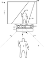
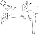
도 1은 사용자의 집에서와 같이 사람(8)이 애플리케이션과 상호작용하는 모션 캡처 시스템의 예시적인 실시형태를 도시한다. 모션 캡처 시스템(10)은 디스플레이(196), 깊이 카메라 시스템(20) 및 컴퓨팅 환경 또는 장치(12)를 포함한다. 깊이 카메라 시스템(20)은 IR(적외선) 광 에미터와 같은 조명기(26), 적외선 카메라와 같은 이미지 센서(26) 및 컬러 (적-녹-청 RGB) 카메라(28)를 갖는 이미징 컴포넌트(22)를 포함할 수 있다. 사용자, 인간 또는 플레이어라고도 지칭되는 사람(8)과 같은 하나 이상의 물체는 깊이 카메라의 시야(6)에 서 있다. 라인(2와 4)는 시야(6)의 경계를 나타낸다. 이 예에서, 깊이 카메라 시스템(20) 및 컴퓨팅 환경(12)은 디스플레이(196) 상의 아바타(197)가 사람(8)의 움직임을 추적하는 애플리케이션을 제공한다. 예를 들어, 사람이 팔을 드는 때에 아바타가 팔을 들 수 있다. 아바타(197)는 3-D 가상 세계에서 길(198) 위에 서 있다. 깊이 카메라 시스템(20)의 초점 길이를 따라, 예를 들어, 수평으로 연장되는 z-축, 수직으로 연장되는 y-축 및 길이방향으로(laterllay) 그리고 수평으로 연장되는 x-축을 포함하는 데카르트 세계 좌표 시스템이 정의될 수 있다. 디스플레이(196)가 y-축 방향으로 수직으로 연장되고 z-축은 y-축과 x-축에 수직으로, 그리고 사용자(8)가 서있는 지표면에 평행하게 깊이 카메라 시스템으로부터 바깥쪽으로 연장하므로, 도면의 관점은 단순화로서 수정되어 있음을 유의하라. 1 illustrates an example embodiment of a motion capture system in which a person 8 interacts with an application, such as at a user's home.
일반적으로, 모션 캡처 시스템(10)은 하나 이상의 사람 타겟을 인식, 분석 및/또는 추적하는데 사용된다. 컴퓨팅 환경(12)은 애플리케이션을 실행하기 위해 컴퓨터, 게임 시스템 또는 콘솔 등뿐만 아니라 하드웨어 컴포넌트 및/또는 소프트웨어 컴포넌트를 포함할 수 있다. In general,
깊이 카메라 시스템(20)은, 사람에 의해 수행되는 제스처 및/또는 움직임이 캡처, 분석 및 추적되어 아바타나 스크린 상의 캐릭터를 움직이거나 사용자 인터페이스(UI)에서 메뉴 아이템을 선택하는 등 애플리케이션 내의 하나 이상의 제어나 동작을 수행할 수 있도록 사람(8)과 같은 하나 이상의 사람을 시각적으로 모니터링하는데 사용될 수 있다. 깊이 카메라 시스템(20)은 아래에서 더 자세히 논의된다.The
모션 캡처 시스템(10)은 디스플레이(196), 예를 들어, 텔레비전, 모니터, 고해상도 텔레비전(HDTV) 등, 또는 심지어 사용자에게 시각 및 청각 출력을 제공하는 벽이나 다른 표면상의 프로젝션과 같은 시청각 장치에 접속될 수 있다. 청각 출력은 별도의 장치를 통해 제공될 수도 있다. 디스플레이를 구동하기 위해, 컴퓨팅 환경(12)은 애플리케이션과 연관되는 시청각 신호를 제공하는 그래픽 카드 등의 비디오 어댑터 및/또는 사운드 카드 등의 오디오 어댑터를 포함할 수 있다. 디스플레이(196)는 컴퓨팅 환경(12)에 접속될 수 있다.
사람(8)은 깊이 카메라 시스템(20)을 이용하여 추적될 수 있으며, 사용자의 제스처 및/또는 움직임은 아바타나 스크린 상의 캐릭터를 움직이기 위해 캡쳐되고 사용되며 또는 컴퓨터 환경(12)에 의해 실행되고 있는 애플리케이션에 대한 입력 제어로서 해석된다.The person 8 can be tracked using the
사람(8)의 일부 움직임은 아바타를 제어하는 것 이외의 동작에 대응할 수 있는 제어로 해석될 수 있다. 예를 들어, 일 실시형태에서, 플레이어는 게임 종료, 중지 또는 저장, 레벨 선택, 하이스코어 보기, 친구와 통신 등을 위해 움직임을 이용할 수 있다. 플레이어는 메인 사용자 인터페이스로부터 게임 또는 기타 애플리케이션을 선택하거나 기타 옵션의 메뉴를 탐색(navigate)하기 위해 움직임을 이용할 수 있다. 그러므로, 애플리케이션과 상호작용하기 위해 적당한 여하한 방식으로 사람(8)의 움직임의 전체 범위가 사용가능하고, 사용되고, 분석될 수 있다.Some movements of the person 8 may be interpreted as controls that may correspond to actions other than controlling the avatar. For example, in one embodiment, a player can use movement to end, stop or save a game, select a level, view a high score, communicate with a friend, and the like. The player can use the movement to select a game or other application from the main user interface or to navigate a menu of other options. Therefore, the full range of movements of the person 8 can be available, used and analyzed in any way appropriate to interact with the application.
모션 캡처 시스템(10)은 엔터테인먼트와 레저를 위한 것인 게임이나 기타 애플리케이션의 영역(realm) 밖에 있는 운영 체제 및/또는 애플리케이션 제어로 타겟 움직임을 해석하는데 더 사용될 수 있다. 예를 들어, 가상적으로 운영 체제 및/또는 애플리케이션의 여하한 제어가능한 태양이 사람(8)의 움직임에 의해 제어될 수 있다.
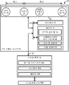
도 2는 도 1의 모션 캡처 시스템의 예시적인 블록도를 도시한다. 깊이 카메라 시스템(20)은 깊이 값을 포함할 수 있는 깊이 이미지를 포함하는 깊이 정보로써, 예를 들어, 비행시간(time-of-flight), 구조광, 스테레오 이미지 등을 포함하는 여하한 적당한 기술을 통해 비디오를 캡처하도록 구성될 수 있다. 깊이 카메라 시스템(20)은 "Z 층(Z layers)" 또는 깊이 카메라로부터 시선을 따라 연장하는 Z 축에 수직일 수 있는 층으로 깊이 정보를 조직(organize)할 수 있다. FIG. 2 shows an exemplary block diagram of the motion capture system of FIG. 1.
깊이 카메라 시스템(20)은 물리적 공간에서 장면의 깊이 이미지를 포착하는 이미징 컴포넌트(22)를 포함할 수 있다. 깊이 이미지 또는 깊이 맵은 캡처된 장면의 2차원(2-D) 픽셀 영역을 포함할 수 있는데, 2-D 픽셀 영역 내 각각의 픽셀은 이미징 컴포넌트(22)로부터 물체까지의 직선 거리를 나타내는 관련 깊이 값을 가져서 3-D 깊이 이미지를 제공한다.
이미징 컴포넌트(22)의 다양한 구성이 가능하다. 한 가지 접근에서, 이미징 컴포넌트(22)는 조명기(26), 제1 이미지 센서(S1)(24), 제2 이미지 센서(S2)(29), 및 가시 컬러 카메라(28)를 포함한다. 센서(S1 및 S2)는 장면의 깊이 이미지를 캡처하는데 사용될 수 있다. 한 가지 접근에서, 조명기(26)는 적외선(IR) 광 에미터이고, 제1 및 제2 센서는 적외선 센서이다. 3-D 깊이 카메라는 조명기(26)와 하나 이상의 센서의 조합에 의해 형성된다. Various configurations of the
깊이 맵은 다양한 기술을 이용하여 각각의 센서에 의해 획득될 수 있다. 예를 들어, 깊이 카메라 시스템(20)은 깊이 정보를 캡처하기 위해 구조광을 사용할 수 있다. 이러한 분석에서, 패터닝된 광(즉, 그리드 패턴이나 스트라이프 패턴과 같은 알려진 패턴으로 표시된 광)이 조명기(26)에 의해 장면에 프로젝션된다. 장면 내의 하나 이상의 타겟 또는 물체의 표면에 부딪히는 때에, 응답으로 패턴이 변형될 수 있다. 이러한 패턴의 변형은 예를 들어, 센서(24 또는 29) 및/또는 컬러 카메라(28)에 의해 캡처될 수 있고 그 후에 깊이 카메라 시스템으로부터 타겟 또는 물체 상의 특정 위치까지의 물리적 거리를 결정하기 위해 분석될 수 있다. Depth maps can be obtained by each sensor using a variety of techniques. For example,
한 가지 가능한 접근에서, 센서(24 및 29)는 조명기(26)의 반대측에, 조명기로부터 상이한 베이스라인 거리에 위치된다. 예를 들어, 센서(24)는 조명기(26)로부터 거리(BL1)에 위치되고, 센서(29)는 조명기(26)로부터 거리(BL2)에 위치된다. 센서와 조명기 사이의 거리는 센서와 조명기의 광 축과 같은 중심점 사이의 거리로 표현될 수 있다. 조명기의 반대측 상에 센서를 갖는 것의 한 가지 장점은, 센서가 상이한 관점에서 물체를 보기 때문에 시야 내 물체의 오클루젼된 영역이 감소 또는 제거될 수 있다는 것이다. 또한, 센서를 조명기에 상대적으로 가깝게 배치함으로써 센서가 시야 내에서 더 가까운 물체를 보는데 최적화될 수 있는 반면, 다른 센서는 조명기로부터 상대적으로 멀리 배치함으로써 시야에서 더 먼 물체를 보는데 최적화될 수 있다. 예를 들어, BL2>BL1이면, 센서(24)는 짧은 범위 이미징에 최적화된 것으로 생각될 수 있는 반면, 센서(29)는 긴 거리 이미징에 최적화된 것으로 생각될 수 있다. 한 가지 접근에서, 센서(24와 29)는 이들이 조명기를 통과하는 공통의 선을 따라 배치되도록 동일선상에 있을 수 있다. 그러나, 센서(24와 29)의 위치에 대한 다른 구성이 가능하다.In one possible approach,
예를 들어, 센서는 스캐닝될 물체 주변에, 또는 홀로그램이 프로젝션될 위치 주변에 배열될 수 있다. 또한 각각 조명기와 센서를 갖는 다수의 깊이 카메라 시스템을 물체 주변에 배열하는 것도 가능하다. 이는 물체의 상이한 측면의 보기를 허용할 수 있어서, 객체 주변의 회전 보기를 제공한다. 더 많은 깊이 카메라를 사용함으로써, 우리는 물체의 더 많은 가시 영역을 부가한다. 2개의 깊이 카메라가 그들의 조명에 의해 서로를 가리지 않는 이상, 2개의 깊이 카메라를 서로를 향하여 하나는 물체의 전면에 하나는 물체의 후면에 가질 수 있다. 각각의 깊이 카메라는 물체로부터 반사되는 그 자신의 구조광 패턴을 감지할 수 있다. 다른 예에서, 2개의 깊이 카메라가 서로에 대해 90도로 배열된다. For example, the sensor may be arranged around the object to be scanned, or around the location where the hologram is to be projected. It is also possible to arrange multiple depth camera systems around the object, each with an illuminator and a sensor. This may allow viewing of different sides of the object, providing a rotational view around the object. By using more depth cameras, we add more visible area of the object. Unless two depth cameras obstruct each other by their illumination, one can have two depth cameras facing each other, one on the front of the object and one on the back of the object. Each depth camera can detect its own structured light pattern reflected from an object. In another example, two depth cameras are arranged at 90 degrees relative to each other.
깊이 카메라 시스템(20)은 3-D 깊이 카메라(22)와 통신하는 프로세서(32)를 포함할 수 있다. 프로세서(32)는, 예를 들어, 깊이 이미지를 수신하는 것, 깊이 이미지에 기초하여 복셀(voxel)의 그리드를 생성하는 것, 사람 타겟과 연관된 하나 이상의 복셀을 고립시키기 위해 복셀의 그리드에 포함된 배경을 제거하는 것, 고립된 사람 타겟의 하나 이상의 극한의 위치 또는 포지션을 결정하는 것, 하나 이상의 극한의 위치 또는 포지션의 기초하여 모델을 조정하는 것을 위한 명령을 포함하는 명령 또는 여하한 기타 적당한 명령을 실행할 수 있는 표준화된 프로세서, 특화된 프로세서, 마이크로프로세서 등을 포함할 수 있으며, 이는 아래에서 더 상세히 설명할 것이다.
프로세서(32)는 구조광 깊이 맵을 도출하는 소프트웨어(33), 스테레오스코픽 비젼 깊이 맵을 도출하는 소프트웨어(34), 깊이 맵 병합 계산을 수행하는 소프트웨어(35)를 사용하기 위해 메모리(31)에 액세스할 수 있다. 프로세서(32)는 조명 평면에서 조명기에 의해 발산되는 구조광의 패턴에 픽셀 데이터의 프레임을 비교함으로써 객체의 구조된 광 깊이 맵을 도출하는 적어도 하나의 제어 회로인 것으로 생각될 수 있다. 예를 들어, 소프트웨어(33)를 이용하여, 적어도 하나의 제어 회로는, 센서(24)에 의해 획득되는 픽셀 데이터의 제1 프레임을 조명기(26)에 의해 발산되는 구조광의 패턴에 비교함으로써 물체의 제1 구조광 깊이 맵을 도출할 수 있고, 센서(29)에 의해 획득되는 픽셀 데이터의 제2 프레임을 구조광의 패턴에 비교함으로써 물체의 제2 구조광 깊이 맵을 도출할 수 있다. 적어도 하나의 제어 회로는 제1 및 제2 구조광 깊이 맵에 기초하는 병합된 깊이 맵을 도출하기 위해 소프트웨어(35)를 사용할 수 있다. 구조광 깊이 맵은, 예를 들어, 도 5(a)와 관련하여 아래에서 더 논의된다. The processor 32 stores the memory 31 in order to use software 33 for deriving the structured light depth map, software 34 for deriving the stereoscopic vision depth map, and software 35 for performing the depth map merging calculation. Can be accessed. The processor 32 may be considered to be at least one control circuit that derives a structured light depth map of an object by comparing a frame of pixel data to a pattern of structured light emitted by the illuminator in the illumination plane. For example, using software 33, the at least one control circuitry may compare the first frame of pixel data obtained by the
또한, 적어도 하나의 제어 회로는, 센서(24)에 의해 획득된 픽셀 데이터의 제1 프레임을 센서(29)에 의해 획득된 픽셀 데이터의 제2 프레임에 스테레오스코픽 매칭함으로써 적어도 물체의 제1 스테레오스코픽 깊이 맵을 도출하고, 픽셀 데이터의 제2 프레임을 픽셀 데이터의 제1 프레임에 스테레오스코픽 매칭함으로써 적어도 물체의 제2 스테레오스코픽 깊이 맵을 도출하기 위해 소프트웨어(34)를 이용할 수 있다. 소프트웨어(25)는 하나 이상의 구조광 깊이 맵 및/또는 스테레오스코픽 깊이 맵을 병합할 수 있다. 스테레오스코픽 깊이 맵은 예를 들어 도 5(b)와 관련하여 아래에서 더 논의된다. In addition, the at least one control circuit may stereoscopically match the first frame of pixel data obtained by the
적어도 하나의 제어 회로가 프로세서(192) 또는 여하한 기타 프로세서와 같은 깊이 카메라 시스템 외부의 프로세서에 의해서도 제공될 수 있다. 적어도 하나의 제어 회로는 메모리(31)로부터의 소프트웨어에 액세스할 수 있는데, 메모리(31)는, 예를 들어, 적어도 하나의 프로세서나 제어기(32)를 여기에 설명된 깊이 카메라 시스템에서 이미지 데이터를 처리하는 방법을 수행하도록 프로그래밍하기 위한 컴퓨터 판독가능 소프트웨어가 포함된 유형의(tangible) 컴퓨터 판독가능 저장소일 수 있다. At least one control circuit may also be provided by a processor external to the depth camera system, such as processor 192 or any other processor. At least one control circuit can access the software from the memory 31, which can be configured to, for example, at least one processor or controller 32 store image data in the depth camera system described herein. It may be a tangible computer readable storage that includes computer readable software for programming to perform a method of processing.
메모리(31)는 프로세서(32)에 의해 실행되는 명령을 저장할 수 있을 뿐만 아니라, 센서나 컬러 카메라에 의해 캡처된 픽셀 데이터(36)의 프레임과 같은 이미지를 저장할 수 있다. 예를 들어, 메모리(31)는 RAM(random access memory), ROM(read only memory), 캐시, 플래시 메모리, 하드 디스크, 또는 여하한 기타의 적합한 유형의(tangible) 컴퓨터 판독가능 저장 컴포넌트를 포함할 수 있다. 메모리 컴포넌트(31)는 버스(21)를 통해 이미지 캡처 컴포넌트(22) 및 프로세서(32)와 통신하는 별도의 컴포넌트일 수 있다. 다른 실시형태에 따르면, 메모리 컴포넌트(31)는 프로세서(32) 및/또는 이미지 캡처 컴포넌트(22)로 통합될 수 있다. The memory 31 may not only store instructions executed by the processor 32 but also store an image, such as a frame of pixel data 36 captured by a sensor or color camera. For example, memory 31 may include random access memory (RAM), read only memory (ROM), cache, flash memory, hard disk, or any other suitable tangible computer readable storage component. Can be. The memory component 31 may be a separate component in communication with the
깊이 카메라 시스템(20)은 유선 및/또는 무선 접속과 같은 통신 링크(37)를 통해 컴퓨팅 환경(12)과 통신할 수 있다. 컴퓨팅 환경(12)은 깊이 카메라 시스템(20)의 시야에 있는 물리적 공간으로부터 언제 이미지 데이터를 캡처할지를 나타내는 클록 신호를 통신 링크(37)를 통해 깊이 카메라 시스템(20)에 제공할 수 있다.
또한, 깊이 카메라 시스템(20)은, 예를 들어, 이미지 센서(24와 29) 및/또는 컬러 카메라(28)에 의해 캡쳐되는 이미지와 깊이 정보, 및/또는 깊이 카메라 시스템(20)에 의해 생성될 수 있는 골격 모델(skeletal model)을 통신 링크(37)를 통해 컴퓨팅 환경(12)에 제공할 수 있다. 그러면 컴퓨팅 환경(12)은 애플리케이션을 제어하기 위해 모델, 깊이 정보 및 캡처된 이미지를 이용할 수 있다. 예를 들어, 도 2에 도시된 바와 같이, 컴퓨팅 환경(12)은, 각각이 (사용자가 움직임에 따라) 골격 모델에 의해 수행될 수 있는 제스처에 관한 정보를 갖는 제스처 필터의 집합과 같은 제스처 라이브러리(190)를 포함할 수 있다. 예를 들어, 손으로 휘두르거나(swiping) 던지는 것(flinging)과 같은 다양한 손 제스처에 대해 제스처 필터가 제공될 수 있다. 검출된 동작을 각각의 필터에 비교함으로써, 사람에 의해 수행되는 구체적인 제스처나 움직임이 식별될 수 있다. 움직임이 수행되는 범위도 결정될 수 있다.Further,
깊이 카메라 시스템(20)에 의해 캡처되는 골격 모델 형태의 데이터와 그와 연관된 움직임은, (골격 모델로 나타내어지는) 사용자가 하나 이상의 구체적인 움직임을 언제 수행했는지를 식별하기 위해 제스처 라이브러리(190) 내의 제스처 필터들에 비교될 수 있다. 이들 움직임은 애플리케이션의 다양한 제어와 연관될 수 있다. The data in the form of a skeletal model captured by the
컴퓨팅 환경은 디스플레이 장치(196)에 시청각 출력 신호를 제공하고 여기에 설명된 다른 기능을 달성하기 위해 메모리(194)에 저장되는 명령을 실행하기 위한 프로세서(192)도 포함할 수 있다. The computing environment may also include a processor 192 for providing audiovisual output signals to the
도 3은 도 1의 모션 캡처 시스템에서 사용될 수 있는 컴퓨팅 환경의 예시적인 블록도를 도시한다. 컴퓨팅 환경은 하나 이상의 제스처나 기타 움직임을 해석하고, 그에 응답하여 디스플레이 상에서 시각적 공간을 업데이트하는데 사용될 수 있다. 상술한 컴퓨팅 환경(12)과 같은 컴퓨팅 환경은 게임 콘솔과 같은 멀티미디어 콘솔(100)을 포함할 수 있다. 멀티미디어 콘솔(100)은 레벨 1 캐시(102), 레벨 2 캐시(104) 및 플래시 ROM(Read Only Memory)(106)를 갖는 CPU(central processing unit)(101)를 갖는다. 레벨 1 캐시(102)와 레벨 2 캐시(104)는 데이터를 일시적으로 저장하고, 따라서 메모리 액세스 사이클의 수를 감소시키며, 그에 의해 처리 스피드와 스루풋(throughput)을 개선한다. 하나 이상의 코어를 갖고, 따라서, 추가의 레벨 1 및 레벨 2 캐시(102와 104)를 갖는 CPU(101)가 제공될 수 있다. 플래시 ROM과 같은 메모리(106)는 멀티미디어 콘솔(100)이 켜지는 때에 부팅 프로세스의 초기 페이즈 동안 로딩되는 실행 코드를 저장할 수 있다.3 illustrates an example block diagram of a computing environment that may be used in the motion capture system of FIG. 1. The computing environment may be used to interpret one or more gestures or other movements and in response to update the visual space on the display. A computing environment, such as the computing environment 12 described above, may include a
GPU(graphic processing unit)(그래픽 처리 유닛)(108) 및 비디오 인코더/비디오 코덱(코더/디코더)(114)은 고속 및 고해상도 그래픽 처리를 위한 비디오 처리 파이프라인을 형성한다. 데이터는 버스를 통해 그래픽 처리 유닛(108)으로부터 비디오 인코더/비디오 코덱(114)으로 운반된다. 비디오 처리 파이프라인은 텔레비전 또는 기타 디스플레이로의 전송을 위해 데이터를 A/V(오디오/비디오) 포트(140)로 출력한다. 프로세서가 RAM(Ramdon Access Memory)과 같은 다양한 타입의 메모리(112)에 액세스하는 것을 용이하게 하도록 메모리 제어기(110)가 GPU(108)에 접속된다.Graphic processing unit (GPU) 108 and video encoder / video codec (coder / decoder) 114 form a video processing pipeline for high speed and high resolution graphics processing. Data is carried from the
멀티미디어 콘솔(100)은 I/O 제어기(120), 시스템 관리 제어기(122), 오디오 처리 유닛(123), 네트워크 인터페이스(124), 제1 USB 호스트 제어기(126), 제2 USB 제어기(128), 및 모듈(118) 상에서 구현되는 것이 바람직한 프론트 패널 I/O 서브어셈블리(130)를 포함한다. USB 제어기(126과 128)는 주변 제어기(142(1)-142(2)), 무선 어댑터(148) 및 외부 메모리 장치(146)(예를 들어, 플래시 메모리, 외부 CD/DVD ROM 드라이브, 제거가능(removable) 매체 등)에 대한 호스트로서 기능한다. 네트워크 인터페이스(NW IF)(124) 및/또는 무선 어댑터(148)는 네트워크(예를 들어, 인터넷, 홈네트워크 등)으로의 액세스를 제공하고, 이더넷 카드, 모뎀, 블루투스 모듈, 케이블 모뎀 등을 포함하는 다양한 유선이나 무선 어댑터 컴포넌트 중 여하한 것일 수 있다.The
부팅 프로세스 동안 로딩되는 애플리케이션 데이터를 저장하기 위해 시스템 메모리(143)가 제공된다. 미디어 드라이브(144)가 제공되며, DVD/CD 드라이브, 하드 드라이브 또는 기타 제거가능 미디어 드라이브를 포함할 수 있다. 미디어 드라이브(144)는 멀티미디어 콘솔(100)의 내부 또는 외부에 있을 수 있다. 애플리케이션 데이터는 멀티미디어 콘솔(100)에 의한 실행, 플래이백 등을 위하여 미디어 드라이브(144)를 통해 액세스될 수 있다. 미디어 드라이브(144)는 직렬 ATA 버스 또는 기타 고속 접속과 같은 버스를 통해 I/O 제어기(120)에 접속된다.
시스템 관리 제어기(122)는 멀티미디어 콘솔(100)의 가용성을 보장하는 것과 관련된 다양한 서비스 기능을 제공한다. 오디오 처리 유닛(123)과 오디오 코덱(132)은 고충실(high fidelity) 및 스테레오 처리를 하는 대응하는 오디오 처리 파이프라인을 형성한다. 오디오 데이터는 통신 링크를 통해 오디오 처리 유닛(123)과 오디오 코덱(132) 사이에서 운반된다. 오디오 처리 파이프라인은 오디오 기능을 갖는 외부 오디오 플레이어나 장치에 의한 재생을 위해 데이터를 A/V 포트(140)로 출력한다.
프론트 패널 I/O 서브어셈블리(130)는 전원 버튼(150)과 꺼냄(eject) 버튼(152) 뿐만 아니라 여하한 LED(light emitting diodes) 또는 멀티미디어 콘솔(100)의 외부 표면에 노출된 기타 표시자의 기능을 지원한다. 시스템 전원 모듈(136)은 멀티미디어 콘솔(100)의 컴포넌트에 전원을 제공한다. 팬(138)은 멀티미디어 콘솔(100) 내의 회로를 냉각한다.The front panel I / O subassembly 130 may include the
CPU(101), GPU(108), 메모리 제어기(110) 및 멀티미디어 콘솔(100) 내 다양한 기타 컴포넌트는, 직렬 및 병렬 버스, 메모리 버스, 주변 버스 및 다양한 버스 아키텍처 중 여하한 것을 이용하는 프로세서 또는 로컬 버스를 포함하는 하나 이상의 버스를 통해 상호접속된다.Various other components in
멀티미디어 콘솔(100)이 켜지면, 애플리케이션 데이터가 시스템 메모리(143)로부터 메모리(112) 및/또는 캐시(102, 104)로 로딩되고 CPU(101) 상에서 실행될 수 있다. 애플리케이션은 멀티미디어 콘솔(100) 상에서 사용가능한 상이한 미디어 타입으로 탐색하는 때에 일관적인 사용자 경험을 제공하는 그래픽 사용자 인터페이스를 제시할 수 있다. 동작에서, 애플리케이션 및/또는 미디어 드라이브(144) 내에 포함된 기타 매체는 멀티미디어 콘솔(100)에 추가적인 기능을 제공하기 위해 미디어 드라이브(144)로부터 론칭 또는 플레이될 수 있다. When the
멀티미디어 콘솔(100)은 시스템을 텔레비전이나 기타 디스플레이에 단순히 접속함으로서 단독(standalone) 시스템으로 동작될 수 있다. 이 단독 모드에서, 멀티미디어 콘솔(100)은 하나 이상의 사용자가 시스템과 상호작용하거나, 영화를 보거나, 음악을 들을 수 있도록 한다. 그러나, 네트워크 인터페이스(124) 또는 무선 어댑터(148)를 통해 사용가능하게 되는 브로드밴드 접속의 통합에 의해, 멀티미디어 콘솔(100)은 또한 더 큰 네트워크 커뮤니티의 참가자로서 동작될 수 있다. The
멀티미디어 콘솔(100)이 켜지는 때에, 하드웨어 리소스의 특정량이 멀티미디어 콘솔 운영 체제에 의한 시스템 사용을 위해 유보된다. 이들 리소스는 메모리(예를 들어, 16MB), CPU와 GPU 사이클(예를 들어, 5%), 네트워킹 대역폭(예를 들어, 8kb) 등의 유보를 포함할 수 있다. 이들 리소스가 시트템 부팅 시간에 유보되므로, 유보된 리소스는 애플리케이션의 관점에서는 존재하지 않는다.When the
구체적으로, 메모리 유보는 론칭 커널, 동시적 시스템 애플리케이션과 드라이버를 포함하기에 충분하게 큰 것이 바람직하다. 유보된 CPU 사용이 시스템 애플리케이션에 의해 사용되지 않는 경우 유휴 스레드(thread)가 여하한 미사용 사이클을 소비하도록, CPU 유보는 바람직하게는 일정하다.Specifically, the memory reservation is preferably large enough to include the launch kernel, concurrent system applications and drivers. CPU reservations are preferably constant so that idle threads spend any unused cycles if the reserved CPU usage is not used by the system application.
GPU 유보와 관련하여, 팝업을 오버레이로 렌더링하기 위한 코드를 스케줄하도록 GPU 인터럽트를 이용함으로써 시스템 애플리케이션에 의해 생성되는 가벼운 메시지(예를 들어, 팝업)가 표시된다. 오버레이에 대해 요구되는 메모리의 양은 오버레이 영역 크기에 의존하고, 오버레이는 바람직하게는 스크린 해상도에 의해 스케일링(scale)된다. 완전한 사용자 인터페이스가 동시적 시스템 애플리케이션에 의해 사용되는 경우, 애플리케이션 해상도에 독립적인 해상도를 사용하는 것이 바람직하다. 스케일러는 주파수를 변경하고 TV 재동기화(resynch)를 유발할 필요가 없도록 이 해상도를 설정하는데 사용될 수 있다. Regarding GPU reservation, a light message (eg, pop-up) generated by the system application is displayed by using the GPU interrupt to schedule code for rendering the pop-up as an overlay. The amount of memory required for the overlay depends on the overlay area size, and the overlay is preferably scaled by the screen resolution. If a complete user interface is used by concurrent system applications, it is desirable to use a resolution that is independent of the application resolution. The scaler can be used to set this resolution so that there is no need to change the frequency and cause TV resynch.
멀티미디어 콘솔(100)이 부팅되고 시스템 리소스가 유보된 후에, 동시적 시스템 애플리케이션은 시스템 기능을 제공하도록 실행된다. 시스템 기능은 상술한 유보된 시스템 리소스 내에서 실행되는 시스템 애플리케이션의 세트에 캡슐화된다. 운영 체제 커널은, 게임 애플리케이션 스레드에 대해 시스템 애플리케이션 스레드인 스레드를 식별한다. 애플리케이션에 일관적인 시스템 리소스 모습을 제공하기 위해 시스템 애플리케이션은 바람직하게는 사전결정된 시간에 사전결정된 간격으로 CPU(101) 상에서 실행되도록 스케줄된다. 스케줄링은 콘솔 상에서 실행되는 게임 애플리케이션에 대한 캐시 혼란을 최소화할 것이다. After the
동시적 시스템 애플리케이션이 오디오를 요구하는 때에, 시간 민감성 때문에 오디오 처리는 게임 애플리케이션과 비동기적으로 스케줄된다. 멀티미디어 콘솔 애플리케이션 관리자(후술함)는 시스템 애플리케이션이 활성인 때에 게임 애플리케이션 오디오 수준(예를 들어, 무음, 감쇠(attenuate))을 제어한다.When simultaneous system applications require audio, audio processing is scheduled asynchronously with the game application because of time sensitivity. The multimedia console application manager (described below) controls the game application audio level (eg, silent, attenuate) when the system application is active.
입력 장치(예를 들어, 제어기(142(1)과 142(2))는 게임 애플리케이션과 시스템 애플리케이션에 의해 공유된다. 입력 장치는 유보된 리소스가 아니고, 시스템 애플리케이션과 게임 애플리케이션 사이에서 각각이 장치의 포커스를 갖도록 전환될 것이다. 애플리케이션 관리자는 바람직하게는 게임 애플리케이션의 지식을 알지 못하고 입력 스트림의 전환을 제어하고 드라이버는 포커스 전환에 대한 상태 정보를 유지한다. 콘솔(100)은 센서(24와 29)를 포함하는 도 2의 깊이 카메라 시스템으로부터 추가 입력을 수신한다. The input devices (e.g., controllers 142 (1) and 142 (2)) are shared by the game application and the system application. The input device is not a reserved resource, but between the system application and the game application, each of the devices The application manager preferably controls the switching of the input stream without knowing the game application's knowledge and the driver maintains status information about the focus switching. Receive additional input from the depth camera system of FIG.
도 4는 도 1의 모션 캡처 시스템에서 사용될 수 있는 컴퓨팅 환경의 다른 예시적인 블록도를 도시한다. 모션 캡처 시스템에서, 컴퓨팅 환경은 하나 이상의 제스처 또는 기타 움직임을 해석하고, 그에 응답하여 디스플레이 상의 시각적 공간을 업데이트하는데 사용될 수 있다. 컴퓨팅 환경(220)은 컴퓨터(241)를 포함하는데, 컴퓨터는 통상 다양한 유형의(tangible) 컴퓨터 판독가능 저장 매체를 포함한다. 이는 컴퓨터(214)에 의해 액세스될 수 있고 휘발성 및 비휘발성 매체, 제거가능 및 비제거가능 매체 모두를 포함하는 여하한 가용 매체일 수 있다. 시스템 메모리(222)는 ROM(read only memeory)(223)과 RAM(random access memeory)(260)과 같은 휘발성 및/또는 비휘발성 메모리의 형태로 컴퓨터 저장 매체를 포함한다. 스타트업 동안 등에 컴퓨터(241) 내의 요소들 사이에서 정보를 전달하는 것을 돕는 기본 루틴을 포함하는 기본 입력/출력 시스템(224)(BIOS)은 통상 ROM(223)에 저장된다. RAM(260)은 통상, 처리 유닛(259)에 의해 즉시 액세스가능하고 및/또는 현재 동작되고 있는 데이터 및/또는 프로그램 모듈을 포함한다. 그래픽 인터페이스(231)는 GPU(229)와 통신한다. 제한이 아니라 예로써, 도 4는 운영 체제(225), 애플리케이션 프로그램(226), 기타 프로그램 모듈(227) 및 프로그램 데이터(228)을 도시한다. 4 illustrates another example block diagram of a computing environment that may be used in the motion capture system of FIG. 1. In a motion capture system, the computing environment can be used to interpret one or more gestures or other movements and in response to update the visual space on the display. Computing environment 220 includes
컴퓨터(241)는 기타 제거가능/비제거가능, 휘발성/비휘발성 컴퓨터 저장 매체, 예를 들어, 비제거가능 비휘발성 자기 매체로부터 판독하거나 이에 기록하는 하드 디스크 드라이브(238), 제거가능 비휘발성 자기 디스크(254)로부터 판독하거나 이에 기록하는 자기 디스크 드라이브(239), 및 CD ROM이나 기타 광 매체와 같은 제거가능 비휘발성 광 디스크(253)로부터 판독하거나 이에 기록하는 광 디스크 드라이브(240)도 포함할 수 있다. 예시적인 동작 환경에서 사용될 수 있는 기타의 제거가능/비제거가능, 휘발성/비휘발성 유형의(tangible) 컴퓨터 판독가능 저장 매체는 자기 테이프 카세트, 플래시 메모리 카드, DVD(digital vesatile disk), 디지털 비디오 테이프, 고체 상태(solid state) RAM, 고체 상태 ROM 등을 포함하지만 이에 제한되지 않는다. 하드 디스크 드라이브(238)는 통상, 인터페이스(234)와 같은 비제거가능 메모리 인터페이스를 통해 시스템 버스(221)에 접속되고, 자기 디스크 드라이브(239)와 광 디스크 드라이브(240)는 통상, 인터페이스(235)와 같은 제거가능 메모리 인터페이스에 의해 시스템 버스(221)에 접속된다.
위에서 설명하고 도 4에 도시된 드라이브와 그들의 관련 컴퓨터 저장 매체는 컴퓨터 판독가능 명령, 데이터 구조, 프로그램 모듈 및 컴퓨터(241)를 위한 기타 데이터의 저장을 제공한다. 예를 들어, 하드 디스크 드라이브(238)는 운영 체제(258), 애플리케이션 프로그램(257), 기타 프로그램 모듈(256) 및 프로그램 데이터(255)를 저장하는 것으로 도시된다. 이들 컴포넌트는 운영 체제(225), 애플리케이션 프로그램(226), 기타 프로그램 모듈(227) 및 프로그램 데이터(228)와 동일하거나 다를 수 있음을 유의하라. 운영 체제(258), 애플리케이션 프로그램(257), 기타 프로그램 모듈(256) 및 프로그램 데이터(255)에는, 최소한 그들이 상이한 사본임을 도시하기 위해 여기서 상이한 번호가 주어진다. 사용자는 키보드(251) 및 보통 마우스, 트랙볼 또는 터치 패드라고 불리는 포인팅 장치(252)와 같은 입력 장치를 통해 컴퓨터(241)로 명령과 정보를 입력할 수 있다. 다른 입력 장치(미도시)는 마이크로폰, 조이스틱, 게임 패드, 위성 접시, 스캐너 등을 포함할 수 있다. 이들 및 다른 입력 장치가 종종 시스템 버스에 결합되는 사용자 입력 인터페이스(236)를 통해 처리 유닛(259)에 접속되지만, 병렬 포트, 게임 포트 또는 USB(universal serial bus)와 같은 다른 인터페이스와 버스 구조에 의해 접속될 수도 있다. 센서(24와 29)를 포함하는 도 2의 깊이 카메라 시스템(20)은 콘솔(100)에 대한 추가의 입력 장치를 정의할 수 있다. 모니터(242) 또는 다른 유형의 디스플레이도 비디오 인터페이스(232)와 같은 인터페이스를 통해 시스템 버스(221)에 접속된다. 모니터에 추가하여, 컴퓨터는 스피커(244)와 프린터(243)와 같은 다른 주변 출력 장치도 포함할 수 있고, 이는 출력 주변 인터페이스(233)를 통해 접속될 수 있다.The drives and their associated computer storage media described above and shown in FIG. 4 provide storage of computer readable instructions, data structures, program modules, and other data for the
컴퓨터(241)는 원격 컴퓨터(246)와 같은 하나 이상의 원격 컴퓨터로의 논리적 접속을 이용하여 네트워크된 환경에서 동작할 수 있다. 원격 컴퓨터(246)는 퍼스널 컴퓨터, 서버, 라우터, 네트워크 PC, 피어 장치 또는 기타 공통 네트워크 노드일 수 있고, 보통, 컴퓨터(241)에 관하여 상술한 요소 중 많은 것 또는 전부를 포함하지만, 도 4에는 메모리 저장 장치(247)만이 도시되었다. 논리적 접속은 LAN(local area network)(245)과 WAN(wide area network)(249)를 포함하지만, 다른 네트워크도 포함할 수 있다. 이러한 네트워킹 환경은 사무실, 기업 범위 컴퓨터 네트워크, 인트라넷 및 인터넷에서 흔하다.
LAN 네트워킹 환경에서 사용되는 때에, 컴퓨터(241)는 네트워크 인터페이스 또는 어댑터(237)를 통해 LAN(245)에 접속된다. WAN 네트워킹 환경에서 사용되는 때에, 컴퓨터(241)는 보통, 모뎀(250) 또는 인터넷과 같은 WAN(249)을 통해 통신을 수립하기 위한 기타 수단을 포함한다. 내부 또는 외부에 있을 수 있는 모뎀(250)은 사용자 인터페이스(236) 또는 기타 적당한 매커니즘을 통해 시스템 버스(221)에 접속될 수 있다. 네트워킹된 환경에서, 컴퓨터(241)에 대해 도시된 프로그램 모듈 또는 그 부분은 원격 메모리 저장 장치에 저장될 수 있다. 제한이 아니라 예로서, 도 4는 원격 애플리케이션 프로그램(248)을 메모리 장치(247) 상에 상주하는 것으로 도시한다. 도시된 네트워크 접속은 예시적인 것이고 컴퓨터 사이에 통신 링크를 수립하는 다른 수단이 사용될 수 있음을 인식할 것이다.When used in a LAN networking environment, the
컴퓨팅 환경은 여기서 설명된 깊이 카메라 시스템에서 이미지 데이터를 처리하기 위한 방법을 수행하도록 적어도 하나의 프로세서를 프로그래밍하기 위한 컴퓨터 판독가능 소프트웨어를 포함하는 유형의(tangible) 컴퓨터 판독가능 저장소를 포함할 수 있다. 유형의 컴퓨터 판독가능 저장소는, 예를 들어, 컴포넌트(31, 194, 222, 234, 235, 230, 253 및 254) 중 하나 이상을 포함할 수 있다. 프로세서는, 예를 들어, 하나 이상의 컴포넌트(32, 192, 229 및 259)를 포함할 수 있다.The computing environment may include tangible computer readable storage including computer readable software for programming at least one processor to perform a method for processing image data in a depth camera system described herein. The tangible computer readable storage can include, for example, one or more of
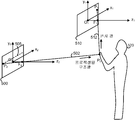
도 5(a)는 구조광 시스템에서 캡처된 프레임과 조명 프레임을 도시한다. 조명 프레임(500)은 조명기의 이미지 평면을 나타내는데, 조명기는 조명기의 시야에서 물체(520)에 구조광을 발산한다. 조명 프레임(500)은 x2, y2 및 z2 수직 축을 갖는 좌표계를 포함한다. F2는 조명기의 초점이고, O2는 조명 프레임(500)의 중심에서와 같은 좌표계의 원점이다. 발산된 구조광은 스트라이프, 스폿(spot) 또는 기타 알려진 조명 패턴을 포함할 수 있다. 유사하게, 캡처된 프레임(510)은 도 2와 관련하여 논의된 센서(24 또는 29)와 같은 센서의 이미지 평면을 나타낸다. 캡처된 프레임(510)은 x1, y1 및 z1 수직 축을 갖는 좌표계를 포함한다. F1은 센서의 초점이고 O1은 캡처된 프레임(510)의 중심에서와 같은 좌표계의 원점이다. 이 예에서, 단순성을 위하여, 이것이 필요한 것은 아니지만, y1과 y2는 동일선상에 정렬되고 z1과 z2는 병렬이다. 또한, 2 이상의 센서가 사용될 수 있지만 단순화를 위해 하나의 센서만 여기 도시된다.5 (a) shows a frame and an illumination frame captured in a structured light system.
조명 프레임(500) 상의 점 P2로부터 발산되는 예시적인 광선(502)와 같은 프로젝션된 구조광선이 조명기 평면에서 상이한 x2, y2 위치로부터 발산된다. 광선(502)은 점 P0에서 물체(520), 예를 들어 사람에 부딪히고, 많은 방향으로 반사된다. 광선(512)은 P0에서 캡처된 프레임(510) 상의 점 P1으로 이동하는 예시적인 반사 광선이다. P1은 센서 내 픽셀에 의해 나타내어져서, 그 x1, y1 위치가 알려진다. 기하학 원리에 의해, P2는 P1, F1 및 F2를 포함하는 평면에 있다. 조명 프레임(500)과 교차하는 이 평면의 부분은 에피-폴라(epi-polar) 라인(505)이다. 구조광의 어떤 부분이 P2에 의해 프로젝션되는지 식별함으로써, 에피-폴라 라인(505)을 따르는 P2의 위치가 식별될 수 있다. P2는 P1의 대응 점이다. 물체의 깊이가 가까울수록, 에피-폴라 라인의 길이가 길다. Projected structured light, such as
후속하여, z1 축에 따른 P0의 깊이는 삼각법(triangulation)으로 결정될 수 있다. 이는 깊이 맵에서 픽셀 P1에 할당되는 깊이 값이다. 조명 프레임(500)의 일부 점에 대해, 오클루젼에 기인하거나 센서의 제한된 시야에 기인하는 등으로 캡처된 프레임(510) 내에 대응 픽셀이 없을 수 있다. 조명 프레임(500)에서 대응 픽셀이 식별되는 캡처된 프레임(510) 내의 각각의 픽셀에 대해, 깊이 값이 획득될 수 있다. 캡처된 프레임(510)에 대한 깊이 값의 세트는 캡처된 프레임(510)에 대한 깊이 맵을 제공한다. 추가의 센서 및 그들 각각의 캡처된 프레임에 대해 유사한 프로세스가 수행될 수 있다. 또한, 비디오 데이터의 연속적인 프레임이 획득되는 때에, 각각의 프레임에 대해 프로세스가 수행될 수 있다.Subsequently, the depth of P 0 along the z 1 axis can be determined by triangulation. This is the depth value assigned to pixel P 1 in the depth map. For some points in the
도 5(b)는 스테레오스코픽 광 시스템 내의 2개의 캡처된 프레임을 도시한다. 스테레오스코픽 처리는, 2개의 프레임에서 대응되는 점이 식별된다는 점에서 도 5(a)에서 설명된 처리와 유사하다. 그러나, 이 경우, 2개의 캡처된 프레임 내의 대응되는 픽셀이 식별되고, 조명이 별도로 제공된다. 조명기(550)는 조명기의 시야에서 물체(520)에 프로젝션된 광을 제공한다. 이 광은 예를 들어 물체에 의해 반사되고 2개의 센서에 의해 감지된다. 제1 센서는 픽셀 데이터의 프레임(530)을 획득하는 반면, 제2 센서는 픽셀 데이터의 프레임(540)을 획득한다. 예시적인 광선(532)은 물체 상의 점 P0에서 프레임(530) 내 픽셀 P2까지 연장하여, 연관된 센서의 초점 F2를 통과한다. 유사하게, 예시적인 광선(542)은 물체 상의 점 P0에서 프레임(540) 내 픽셀 P1까지 연장하여, 연관된 센서의 초점 F1를 통과한다. 프레임(540)의 관점에서, 스테레오 매칭에는 P1에 대응하는 에피-폴라 라인(545) 상의 점 P2를 식별하는 것이 관여될 수 있다. 유사하게, 프레임(530)의 관점에서, 스테레오 매칭에는 P2에 대응하는 에피-폴라 라인(548) 상의 점 P1을 식별하는 것이 관여될 수 있다. 그러므로, 스테레오 매칭은 한 쌍의 프레임 중 각 프레임에 대해 한 번씩 별도로 수행될 수 있다. 일부 경우에, 제1 프레임으로부터 제2 프레임으로의 한 방향의 스테레오 매칭이 제2 프레임으로부터 제1 프레임으로의 다른 방향의 스테레오 매칭을 수행하지 않고 수행될 수 있다.5 (b) shows two captured frames in a stereoscopic optical system. Stereoscopic processing is similar to the processing described in FIG. 5 (a) in that corresponding points in two frames are identified. In this case, however, the corresponding pixels in the two captured frames are identified and the illumination is provided separately.
z1 축에 따른 P0의 깊이는 삼각법에 의해 결정될 수 있다. 이는 픽셀 깊이 맵에서 픽셀 P1에 할당되는 깊이 값이다. 프레임(540) 내 일부 점에 대해, 오클루젼에 기인하거나 센서의 제한된 시야에 기인하는 등으로 프레임(530) 내에 대응 픽셀이 없을 수 있다. 프레임(530)에서 대응 픽셀이 식별되는 프레임(540) 내의 각각의 픽셀에 대해, 깊이 값이 획득될 수 있다. 프레임(540)에 대한 깊이 값의 세트는 프레임(540)에 대한 깊이 맵을 제공한다. The depth of P 0 along the z 1 axis can be determined by trigonometry. This is the depth value assigned to pixel P 1 in the pixel depth map. For some points in
유사하게, z2 축에 따른 P2의 깊이는 삼각법에 의해 결정될 수 있다. 이는 픽셀 깊이 맵에서 픽셀 P2에 할당되는 깊이 값이다. 프레임(530) 내 일부 점에 대해, 오클루젼에 기인하거나 센서의 제한된 시야에 기인하는 등으로 프레임(540) 내에 대응 픽셀이 없을 수 있다. 프레임(540)에서 대응 픽셀이 식별되는 프레임(530) 내의 각각의 픽셀에 대해, 깊이 값이 획득될 수 있다. 프레임(530)에 대한 깊이 값의 세트는 프레임(530)에 대한 깊이 맵을 제공한다. Similarly, the depth of P 2 along the z 2 axis can be determined by trigonometry. This is the depth value assigned to pixel P 2 in the pixel depth map. For some points within
유사한 프로세스가 추가의 센서 및 그들 각각의 캡처된 프레임에 대해 수행될 수 있다. 또한, 비디오 데이터의 연속적인 프레임이 획득되는 때에, 각각의 프레임에 대해 프로세스가 수행될 수 있다.Similar processes can be performed for additional sensors and their respective captured frames. In addition, when successive frames of video data are obtained, a process may be performed for each frame.
도 6(a)는 조명기의 공통 측에 2개의 센서를 갖는 이미징 컴포넌트(600)를 도시한다. 조명기(26)는 구조광 패턴으로 시야 내의 사람 타겟이나 기타 물체를 조명하는 프로젝터이다. 광원은, 예를 들어, 0.75 ㎛ -1.4 ㎛의 파장을 갖는 근적외선 광, 3 ㎛ - 8 ㎛의 파장을 갖는 중파장 적외선 광 및 사람에 의해 발산되는 적외선 방사에 가장 가까운 열 이미징 영역인 8 ㎛ - 15 ㎛의 파장을 갖는 장파장 적외선 광을 포함하는 700 nm - 3,000 nm의 파장을 갖는 적외선 레이저일 수 있다. 조명기는 레이저광을 수신하고 다수의 산란된 광 빔을 출력하는 DOE(diffractive optical element)를 포함할 수 있다. 일반적으로, DOE는 단일의 시준된(collimated) 광 빔으로부터의, 1000개의 작은 광 빔과 같은 다수의 작은 광 빔을 제공하는데 사용된다. 각각의 작은 광 빔은 단일의 시준된 광 빔의 전력의 작은 부분을 갖고, 작은 산란 광 빔은 명목상(nominally) 동일한 강도를 가질 수 있다.6 (a) shows an
작은 광 빔은 희망의 사전결정된 패턴으로 조명기의 시야를 정의한다. DOE는 빔 복제기(replicator)이고, 그래서 모든 출력 빔은 입력 빔과 동일한 기하학적 구조(geometry)를 갖는다. 예를 들어, 모션 트래킹 시스템에서, 방 안에 서거나 앉아 있는 사람 타겟의 추적을 허용하는 방식으로 방을 조명하는 것이 바람직할 수 있다. 전체 사람 타겟을 추적하기 위해, 시야는 충분히 넓은 각도와, 높이 및 폭으로 확장되어 사람의 전체 높이와 넓이 그리고 사람이 모션 트래킹 시스템의 애플리케이션과 상호작용하는 때에 움직일 수 있는 영역을 조명하여야 한다. 팔을 머리 위로 올리거나 양 쪽으로 뻗을 때의 팔 범위, 사람이 애플리케이션과 상호작용하는 때에 움직일 수 있는 영역의 크기, 카메라로부터의 사람의 기대 거리와 카메라의 초점 길이를 포함하여, 사람의 기대 키와 넓이와 같은 인자에 기초하여 적당한 시야가 설정될 수 있다.The small light beam defines the field of view of the illuminator in the desired predetermined pattern. The DOE is a beam replicator, so all output beams have the same geometry as the input beams. For example, in a motion tracking system, it may be desirable to illuminate the room in a manner that allows tracking of a person target standing or sitting in the room. In order to track the entire human target, the field of view must expand to a wide enough angle, height and width to illuminate the overall height and width of the person and the area in which the person can move when interacting with the application of the motion tracking system. The height of the person's expectations, including the arm's range when the arm is raised above or extended to both sides, the size of the movable area when the person interacts with the application, the person's expected distance from the camera, and the camera's focal length; An appropriate field of view may be set based on factors such as area.
전술한 RGB 카메라(28)도 제공될 수 있다. RGB 카메라는 도 6(b) 및 6c에서도 제공될 수 있지만 단순화를 위해 도시되지 않는다.The above-described
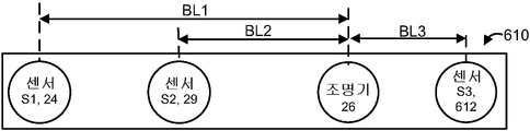
이 예에서, 센서(24와 29)는 조명기(26)의 공통측에 있다. 센서(24)는 조명기(26)로부터 베이스라인 거리(BL1)에 있고, 센서(29)는 조명기(26)로부터 베이스라인 거리(BL2)에 있다. 센서(29)는 더 작은 베이스라인에 의해 짧은 범위 이미징에 최적화되는 반면, 센서(24)는 더 긴 베이스라인에 의해 긴 범위 이미징에 최적화된다. 또한, 조명기의 일 측에 모든 센서를 배치함으로써, 크기가 제한된 하우징을 보통 포함하는 이미징 컴포넌트(600)의 고정된 크기에 대해, 조명기로부터 더 먼 센서에 대해 더 긴 베이스라인이 달성될 수 있다. 반면, 더 짧은 베이스라인은, 주어진 초점 길이를 가정하면, 센서가 더 가까운 물체에 초점을 맞출 수 있어서 짧은 거리에 대해 더 정확한 깊이 측정이 가능하게 되므로, 짧은 범위 이미징을 개선한다. 더 짧은 베이스라인은 더 작은 디스패리티(disparity)와 최소 오클루젼을 가져온다.In this example,
더 긴 베이스라인은, 대응하는 점의 광선 사이의 각이 더 크므로, 즉 이미지 픽셀이 더 작은 거리 차이를 검출할 수 있으므로, 긴 범위 이미징의 정확도를 개선한다. 예를 들어, 도 5(a)에서, 광(502와 512) 사이의 각도는 프레임(500과 510)이 더 멀리 떨어지면 더 커질 것이라는 것을 알 수 있다. 그리고, 도 5(b)에서, 광(532와 542) 사이의 각도는 프레임(530과 540)이 더 멀리 떨어지면 더 커질 것이라는 것을 알 수 있다. 센서가 더 멀리 떨어져서 광선 사이의 각도가 크면 깊이를 결정하기 위한 삼각법 프로세스가 더 정확하다.Longer baselines improve the accuracy of long range imaging because the angle between the rays of the corresponding points is greater, ie the image pixels can detect smaller distance differences. For example, in FIG. 5 (a), it can be seen that the angle between
짧은 범위 또는 긴 범위 이미징 중 어떤 것이 최적화되는지에 따라 센서에 대해 최적 베이스라인을 설정하는 것에 추가하여, 이미징 컴포넌트(600)의 하우징의 제한 내에서, 센서의 다른 특성이 짧거나 긴 범위 이미징을 최적화하기 위하여 설정될 수 있다. 예를 들어, 카메라의 공간 해상도가 최적화될 수 있다. CCD(charge-couple device)와 같은 센서의 공간 해상도는 픽셀의 수와 프로젝션된 이미지에 대한 그 크기의 함수이고, 센서에 의해 세부사항이 얼마나 정밀하게 측정되는지의 척도이다. 짧은 거리 이미징에 최적화된 센서에 대해, 긴 거리 이미징에 최적화된 센서에 비해 낮은 공간 해상도가 수용가능할 수 있다. 낮은 공간 해상도는 프레임 내에서 상대적으로 적은 수의 픽셀 및/또는 상대적으로 큰 픽셀을 사용함으로써 얻어질 수 있는데, 이는 시야 내 검출된 물체의 짧은 깊이 때문에 프로젝트 이미지에 대한 픽셀의 크기가 상대적으로 크기 때문이다. 이는 비용 절감과 에너지 소비 감소를 가져올 수 있다. 반면, 긴 범위 이미징에 최적화된 센서에 대해, 짧은 범위 이미징에 최적화된 센서에 비해 더 높은 공간 해상도가 사용되어야 한다. 더 높은 공간 해상도는 프레임 내의 상대적으로 많은 픽셀 및/또는 상대적으로 작은 픽셀을 이용함으로써 달성될 수 있는데, 이는 시야 내 검출된 물체의 긴 깊이 때문에 프로젝트 이미지에 대한 픽셀의 크기가 상대적으로 작기 때문이다. 더 높은 공간 해상도는 깊이 측정에 있어 더 높은 정확성을 가져온다.In addition to setting an optimal baseline for the sensor depending on whether short range or long range imaging is optimized, other characteristics of the sensor optimize short or long range imaging within the limits of the housing of the
짧거나 긴 범위 이미징을 최적화하기 위해 설정될 수 있는 센서의 다른 특성은 감도(sensitivity)이다. 감도는 입사 광에 센서가 반응하는 범위를 지칭한다. 감도의 한 가지 척도는 양자 효율성(quantum efficiency)인데, 이는 픽셀과 같은 센서의 광반응(photoreactive) 표면에 입사하여 전자-정공 쌍을 산출하는 광자의 퍼센티지이다. 짧은 범위 이미징에 최적화된 센서에 대해, 더 낮은 감도가 수용가능한데, 이는 센서로 광자를 반사하는 물체의 가까운 거리 때문에 더 많은 광자가 각각의 픽셀에 입사할 것이기 때문이다. 더 낮은 감도는, 예를 들어, 낮은 품질의 센서를 이용하여 달성할 수 있고, 이는 비용 절감 가져온다. 반면, 긴 범위 이미징을 위해 최적화된 센서에 대해, 짧은 거리 이미징에 최적화된 센서에 비해 더 높은 감도가 사용되어야 한다. 센서로 광자를 반사하는 물체의 먼 거리 때문에 상대적으로 더 적은 광자가 각각의 픽셀에 입사하는 경우에 검출을 가능하게 하기 위해, 높은 감도는 고품질 센서를 이용하여 달성될 수 있다.Another characteristic of sensors that can be set to optimize short or long range imaging is sensitivity. Sensitivity refers to the range in which the sensor responds to incident light. One measure of sensitivity is quantum efficiency, which is the percentage of photons that enter the photoreactive surface of a sensor, such as a pixel, to produce an electron-hole pair. For sensors optimized for short range imaging, lower sensitivity is acceptable because more photons will enter each pixel due to the close distance of the object reflecting the photons to the sensor. Lower sensitivity can be achieved, for example, using low quality sensors, which leads to cost savings. On the other hand, for sensors optimized for long range imaging, higher sensitivity should be used compared to sensors optimized for short distance imaging. High sensitivity can be achieved using high quality sensors to enable detection when relatively fewer photons enter each pixel due to the long distance of the object reflecting the photons to the sensor.
짧거나 긴 범위 이미징을 최적화하기 위해 설정될 수 있는 센서의 다른 특성은 노출 시간이다. 노출 시간은 이미지 데이터의 프레임을 획득하는 프로세스 동안 센서의 픽셀 상에 광이 떨어지도록 허용되는 시간, 예를 들어, 카메라 셔터가 열리는 시간이다. 노출 시간 동안, 센서의 픽셀은 전하를 축적 또는 집적한다. 더 긴 노출시간은 낮은 감도를 보상할 수 있다는 점에서 노출 시간은 감도와 관련된다. 그러나, 짧은 범위에서 모션 시퀀스를 정확하게 캡처하기 위해서는 짧은 노출 시간이 바람직한데, 이는 물체가 가까울 때에는 이미징되는 물체의 주어진 움직임이 더 큰 픽셀 오프셋으로 번역되기 때문이다. 짧은 범위 이미징에 최적화된 센서에 대해 짧은 노출 시간이 사용될 수 있는 반면, 긴 범위 이미징에 최적화된 센서에 대해 긴 노출 시가닝 사용될 수 있다. 적당한 노출시간을 사용함으로써, 가까운 물체의 과다노출(over exposure)/이미지 포화(saturation)와 먼 물체의 과소노출(under exposure)를 피할 수 있다.Another characteristic of the sensor that can be set to optimize short or long range imaging is exposure time. The exposure time is the time at which light is allowed to fall on the pixels of the sensor during the process of acquiring a frame of image data, for example the time when the camera shutter is opened. During the exposure time, the pixels of the sensor accumulate or accumulate charge. Exposure time is related to sensitivity in that longer exposure times can compensate for lower sensitivity. However, short exposure times are desirable for capturing motion sequences accurately in a short range, since given motion of the object being imaged translates to a larger pixel offset when the object is near. Short exposure times may be used for sensors optimized for short range imaging, while long exposure thinning may be used for sensors optimized for long range imaging. By using an appropriate exposure time, overexposure / image saturation of near objects and under exposure of distant objects can be avoided.
도 6(b)는 조명기의 일 측에 2개의 센서를 갖고 조명기의 반대측에 하나의 센서를 갖는 이미징 컴포넌트(610)를 도시한다. 이러한 방식으로 제3의 센서를 추가하는 것은 더 적은 오클루젼으로 객체를 이미징하게 할 수 있을 뿐만 아니라, 획득되는 추가의 깊이 측정치 때문에 더 정확한 이미징을 가져올 수 있다. 센서(612)와 같은 하나의 센서는 조명기에 가까이 위치될 수 있는 반면, 다른 2개의 센서는 조명기의 반대측에 있다. 이 예에서, 센서(24)는 조명기(26)로부터 베이스라인 거리(BL1)에 있고, 센서(29)는 조명기(26)로부터 베이스라인 거리(BL2)에 있으며, 제3 센서(612)는 조명기(26)로부터 베이스라인 거리(BL3)에 있다.6B shows an
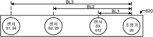
도 6(c)는 조명기의 공통 측에 3개의 센세를 갖는 이미징 컴포넌트(620)를 도시한다. 이러한 방식으로 제3의 센서를 부가하는 것은 획득되는 추가의 깊이 측정치 때문에 더 정확한 이미징을 가져올 수 있다. 또한, 각각의 센서는 상이한 깊이 범위에 대해 최적화될 수 있다. 예를 들어, 조명기로부터 긴 베이스라인 거리(BL3)에서 센서(24)는 긴 범위 이미징에 대해 최적화될 수 있다. 조명기로부터 중간 베이스라인 거리(BL2)에서 센서(29)는 중간 범위 이미징에 대해 최적화될 수 있다. 그리고, 조명기로부터 작은 베이스라인 거리(BL1)에서 센서(612)는 짧은 범위 이미징에 대해 최적화될 수 있다. 유사하게, 공간 해상도, 감도 및/또는 노출 시간은 센서(24)에 대해 긴 범위 레벨, 센서(29)에 대해 중간 범위 레벨, 그리고 센서(612)에 대해 짧은 범위 레벨에 최적화될 수 있다.6 (c) shows an
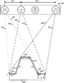
도 6(d)는 조명기의 반대측에 2개의 센서를 갖는 이미징 컴포넌트(630)를 도시하며, 2개의 센서가 물체의 상이한 부분을 감지하는 방법을 보여준다. 센서 S1(24)는 조명기(26)로부터 베이스라인 거리(BL1)에 있고, 짧은 범위 이미징에 대해 최적화된다. 센서 S2(29)는 조명기(26)로부터 베이스라인 거리(BL2 > BL1)에 있고, 긴 범위 이미징에 대해 최적화된다. RGB 카메라(28)도 도시된다. 물체(660)는 시야에 존재한다. 도면의 관점은 단순화로서, 이미징 컴포넌트(630)는 전면(front view)으로 도시되고 물체(660)는 평면(top view)으로 도시되는 것으로 수정됨을 유의하라. 광선(640 및 642)은 조명기(26)에 의해 프로젝션되는 예시적인 광선이다. 광선(632, 634 및 636)은 센서 S1(24)에 의해 감지되는 예시적 반사광선이고, 광선(650과 652)은 센서 S2(29)에 의해 감지되는 예시적 반사광선이다.6 (d) shows an
물체는 센서 S1(24)와 S2(29)에 의해 감지되는 5개의 표면을 포함한다. 그러나, 오클루젼에 의해, 모든 표면이 양 센서에 의해 감지되는 것은 아니다. 예를 들어, 표면(661)은 센서 S1(24)만에 의해 감지되고, 센서 S2(29)의 관점으로부터 가려진다(occluded). 표면(662)도 센서 S1(24)만에 의해 감지되고 센서 S2(29)의 관점으로부터 가려진다. 표면(663)은 센서 S1 및 S2 모두에 의해 감지된다. 표면(664)은 센서 S2만에 의해 감지되고 센서 S1의 관점으로부터 가려진다. 표면(665)은 센서 S2만에 의해 감지되고 센서 S1의 관점으로부터 가려진다. 표면(666)은 센서 S1과 S2 모두에 의해 감지된다. 이는 제2 센서 또는 기타 추가 센서의 부가가 그렇지 않으면 가려졌을 물체의 부분을 이미징하는데 사용될 수 있는 방법을 나타낸다. 또한, 오클루젼을 최소화하기 위해 조명기로부터 가능한 멀리 센서를 배치하는 것이 종종 바람직하다. The object includes five surfaces sensed by
도 7(a)는 시야의 깊이 맵을 획득하기 위한 프로세스를 도시한다. 단계(700)는 구조광의 패턴으로 시야를 조명하는 것을 포함한다. 코딩된 구조광을 포함하는 여하한 타입의 구조광이 사용될 수 있다. 단계 702와 704는 적어도 부분적으로 동시에 수행될 수 있다. 단계 702는 픽셀 데이터의 제1 프레임을 획득하기 위해 제1 센서에서 반사된 적외선 광을 검출하는 것을 포함한다. 이 픽셀 데이터는, 예를 들어, 시야로부터 픽셀에 입사된 광의 양의 표시로서, 노출 시간 동안 각각의 픽셀에 의해 누적된 전하의 양을 나타낼 수 있다. 유사하게, 단계 704는 픽셀 데이터의 제2 프레임을 획득하기 위해 제2 센서에서 반사된 적외선 광을 검출하는 것을 포함한다. 단계 706은 병합된 깊이 맵을 도출하기 위해 모든 프레임으로부터의 픽셀 데이터를 처리하는 것을 포함한다. 이는 도 7(b)-7e와 관련하여 더 설명하는 등의 다른 기술이 관여될 수 있다. 단계 708에서 병합된 깊이 맵에 기초하여 제어 입력을 애플리케이션으로 제공하는 것을 포함한다. 이 제어 입력은 디스플레이 상에서 아바타의 위치를 업데이트하는 것, 사용자 인터페이스(UI)에서 메뉴 아이템을 선택하는 것, 또는 많은 다른 가능한 동작 등의 다양한 목적으로 사용될 수 있다. 7A shows a process for obtaining a depth map of a field of view. Step 700 includes illuminating the field of view with a pattern of structured light. Any type of structured light can be used, including coded structured light. Steps 702 and 704 may be performed at least partially simultaneously. Step 702 includes detecting infrared light reflected at the first sensor to obtain a first frame of pixel data. This pixel data may, for example, be an indication of the amount of light incident on the pixel from the field of view, and may represent the amount of charge accumulated by each pixel during the exposure time. Similarly, step 704 includes detecting infrared light reflected at the second sensor to obtain a second frame of pixel data. Step 706 includes processing pixel data from all frames to derive the merged depth map. This may involve other techniques, such as further described with respect to FIGS. 7B-7E. And providing control inputs to the application based on the merged depth map at step 708. This control input can be used for a variety of purposes, such as updating the avatar's position on the display, selecting a menu item in a user interface (UI), or many other possible actions.
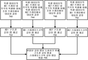
도 7(b)는 도 7(a)의 단계 706을 더 상세히 도시하는데, 여기서 2개의 구조광 깊이 맵이 병합된다. 이 접근에서, 제1 및 제2 구조광 깊이 맵이 각각 제1 및 제2 프레임으로부터 획득되고, 2개의 깊이 맵이 병합된다. 프로세스는 2 이상의 깊이 맵 중 여하한 수를 병합하는 것으로 확장될 수 있다. 구체적으로, 단계 720에서, (도 7(a)의 단계 702에서 획득된) 픽셀 데이터의 제1 프레임 내 각각의 픽셀에 대해, 구조광의 패턴을 매칭함으로서 조명 프레임 내 대응 점을 결정하려는 시도가 이루어진다. 일부 경우에, 오클루젼 또는 기타 요인에 의해, 조명 프레임 내의 대응 점은 제1 프레임의 하나 이상의 픽셀에 대해 성공적으로 결정되지 않을 수 있다. 단계 722에서, 제1 구조광 깊이 맵이 제공된다. 이 깊이 맵은 제1 프레임 내 각각의 픽셀과 대응하는 깊이 값을 식별할 수 있다. 유사하게, 단계724에서, (도 7(a)의 단계 704에서 획득된) 픽셀 데이터의 제2 프레임 내 각각의 픽셀에 대해, 조명 프레임 내 대응 점을 결정하려는 시도가 이루어진다. 일부 경우에, 오클루젼 또는 기타 요인에 의해, 조명 프레임 내의 대응 점은 제2 프레임의 하나 이상의 픽셀에 대해 성공적으로 결정되지 않을 수 있다. 단계 726에서, 제2 구조광 깊이 맵이 제공된다. 이 깊이 맵은 제2 프레임 내 각각의 픽셀과 대응하는 깊이 값을 식별할 수 있다. 단계 720 및 722는 단계 724 및 726과 적어도 부분적으로 동시에 수행될 수 있다. 단계 728에서, 구조광 깊이 맵이 병합되어 도 7(a)의 단계 706의 병합된 깊이 맵을 도출한다.FIG. 7B illustrates step 706 of FIG. 7A in more detail, where the two structured light depth maps are merged. In this approach, the first and second structured light depth maps are obtained from the first and second frames, respectively, and the two depth maps are merged. The process can be extended to merging any number of two or more depth maps. Specifically, in step 720, for each pixel in the first frame of pixel data (obtained in step 702 of FIG. 7A), an attempt is made to determine a corresponding point in the illumination frame by matching a pattern of structured light. . In some cases, due to occlusion or other factors, the corresponding point in the illumination frame may not be determined successfully for one or more pixels of the first frame. In step 722, a first structured light depth map is provided. This depth map can identify a depth value corresponding to each pixel in the first frame. Similarly, in step 724, for each pixel in the second frame of pixel data (obtained in step 704 of FIG. 7A), an attempt is made to determine the corresponding point in the illumination frame. In some cases, due to occlusion or other factors, the corresponding point in the illumination frame may not be determined successfully for one or more pixels of the second frame. In step 726, a second structured light depth map is provided. This depth map can identify a depth value corresponding to each pixel in the second frame. Steps 720 and 722 may be performed at least partially concurrently with steps 724 and 726. In step 728, the structured light depth map is merged to derive the merged depth map of step 706 of FIG. 7 (a).
병합은 비가중 평균, 가중 평균, 정확한 측정 및/또는 신뢰 척도가 관여되는 접근을 포함하는 다른 접근에 기초할 수 있다. 한 가지 접근에서, 각 픽셀에 대해, 2 이상의 깊이 맵 사이에서 깊이 값이 평균된다. 제1 프레임 내 i번째 픽셀에 대한 깊이 값 d1 및 제2 프레임 내 i 번째 픽셀에 대한 깊이 값 d2의 예시적인 비가중 평균은 (dl+d2)/2이다. 제1 프레임 내 i번째 픽셀에 대한 가중치 w1의 깊이 값 d1 및 제2 프레임 내 i 번째 픽셀에 대한 가중치 w2의 깊이 값 d2의 예시적인 가중 평균은 (wl *dl+w2*d2)/[(wl+w2)]이다. 깊이 값을 병합하는 한 가지 접근은, 센서와 조명기 사이의 베이스라인 거리에 기초하여 프레임의 깊이 값에 가중치를 할당하여, 더 높은 신뢰를 나타내는 더 높은 가중치가 베이스라인 거리가 클 때 할당되고, 더 낮은 신뢰를 나타내는 더 낮은 가중치가 베이스라인 거리가 작을 때 할당된다. 이는 더 큰 베이스라인 거리가 더 정확한 깊이 값을 낳기 때문이다. 예를 들어, 도 6(d)에서, 센서 S1으로부터의 깊이 값에 wl=BLl/(BLl+BL2)의 가중치를 할당하고 센서 S2로부터의 깊이 값에 w2=BL2/(BLl+BL2)의 가중치를 할당할 수 있다. 설명하면, BL=1이고 BL=2 거리 단위라고 가정하면, wl=l/3 이고 w2=2/3. 가중치는 픽셀마다 또는 깊이 값마다 적용될 수 있다.Merging may be based on other approaches, including those involving weighted averages, weighted averages, accurate measurements, and / or confidence measures. In one approach, for each pixel, the depth value is averaged between two or more depth maps. An exemplary unweighted average of the
상술한 예는 이미지의 센서 S1으로부터의 이미지를 도 6(d)의 거리 BL1+BL2에 기초하여 센서 S2로부터의 이미지로 스테레오스코픽 매칭하는 것으로부터 획득되는 깊이 값으로 증가될 수 있다. 이 경우, 센서 S1으로부터의 깊이 값에 wl=BLl/(BLl+BL2+BLl+BL2)를 할당하고, S2로부터의 깊이 값에 가중치 w2=BL2/(BLl+BL2+BLl+BL2)를 할당하고, S1을 S2으로 스테레오스코픽 매칭하는 것으로부터 얻어진 깊이 값에 가중치 w3=(BLl+BL2)/(BLl+BL2+BLl+BL2)를 할당할 수 있다. 설명하자면, BL=1이고 BL=2 거리 단위라고 가정하면, wl=l/6, w2=2/6 이고 w3=3/6이다. 추가의 증가에서, 이미지의 센서 S2로부터의 이미지를 도 6(d)의 센서 S1로부터의 이미지로 스테레오스코픽 매칭하는 것으로부터 깊이 값이 획득된다. 이 경우, S1으로부터의 깊이 값에 wl=BLl/(BLl+BL2+BLl+BL2+BLl+BL2)를 할당하고, S2로부터의 깊이 값에 가중치 w2=BL2/(BLl+BL2+BLl+BL2+BLl+BL2)를 할당하고, S1을 S2에 스테레오스코픽 매칭하는 것으로부터 획득된 깊이 값에 가중치 w3=(BLl+BL2)/(BLl+BL2+BLl+BL2+BLl+BL2)를 할당하고, S2를 S1에 스테레오스코픽 매칭하는 것으로부터 얻어진 깊이 값에 가중치 w4=(BLl+BL2)/(BLl+BL2+BLl+BL2+BLl+BL2)를 할당할 수 있다. 설명하자면, BL=1이고 BL=2 거리 단위라고 가정하면, wl=l/9, w2=2/9, w3=3/9 이고 w4=3/9이다. 이는 하나의 가능성일 뿐이다.The above-described example can be increased to a depth value obtained from stereoscopic matching of an image from sensor S1 of the image to the image from sensor S2 based on the distance BL1 + BL2 of FIG. 6 (d). In this case, wl = BLl / (BLl + BL2 + BLl + BL2) is assigned to the depth value from the sensor S1, and the weight w2 = BL2 / (BLl + BL2 + BLl + BL2) is assigned to the depth value from S2. , Weights w3 = (BLl + BL2) / (BLl + BL2 + BLl + BL2) can be assigned to depth values obtained from stereoscopic matching of S1 to S2. To explain, assuming that BL = 1 and BL = 2 distance units, wl = l / 6, w2 = 2/6 and w3 = 3/6. In a further increase, the depth value is obtained from stereoscopic matching of the image from sensor S2 of the image with the image from sensor S1 of FIG. 6 (d). In this case, wl = BLl / (BLl + BL2 + BLl + BL2 + BLl + BL2) is assigned to the depth value from S1, and the weight w2 = BL2 / (BLl + BL2 + BLl + BL2 + is assigned to the depth value from S2. Assigns BLl + BL2), assigns the weight w3 = (BLl + BL2) / (BLl + BL2 + BLl + BL2 + BLl + BL2) to the depth value obtained from stereoscopic matching S1 to S2, and S2 Can be assigned a weight w4 = (BLl + BL2) / (BLl + BL2 + BLl + BL2 + BLl + BL2) to the depth value obtained from stereoscopic matching of S1. To explain, assuming BL = 1 and BL = 2 distance units, wl = l / 9, w2 = 2/9, w3 = 3/9 and w4 = 3/9. This is only one possibility.
가중치는, 높은 신뢰 척도를 갖는 깊이 값이 높은 가중치를 할당받도록 신뢰 척도에 기초하여 제공될 수도 있다. 한 가지 접근에서, 초기 신뢰 척도가 각각의 픽셀에 할당되고, 프레임마다 물체의 깊이가 빨리 변화하지 않는다는 가정에 기초하여, 공차(tolerance) 내에서 깊이 값이 동일하거나 거의 동일한 각각의 새로운 프레임에 대해 신뢰 척도가 증가된다. 예를 들어, 초당 30 프레임의 프레임 레이트에서, 추적되는 사람은 프레임 사이에서 현저하게 움직이지 않을 것이다. 더 상세한 사항에 대해서는, 여기에 참조로 포함되는, 91년 8월 13일 발행 미국 특허 5,040,116, 명칭 "Visual navigation and obstacle avoidance structured light system"을 참조하라. 다른 접근에서, 신뢰 척도는 깊이 값에서의 노이즈 척도이다. 예를 들어, 실제로는 이웃하는 픽셀 사이에서 깊이 값의 큰 변화는 일어나기 어렵다는 가정 하에서, 이러한 깊이 값의 큰 변화는 큰 노이즈를 나타낼 수 있고, 낮은 신뢰 척도를 가져온다. 더 상세한 사항에 대해서는, 여기에 참조로 포함되는, 04년 6월 15일 발행 미국 특허 6,751,338, 명칭 "System and method of using range image data with machine vision tools"을 참조하라. 신뢰 척도를 할당하기 위한 다른 접근도 가능하다.The weight may be provided based on the confidence measure such that a depth value with a high confidence measure is assigned a high weight. In one approach, for each new frame with the same or nearly the same depth value within tolerance, based on the assumption that an initial confidence measure is assigned to each pixel and the depth of the object does not change quickly from frame to frame. The confidence measure is increased. For example, at a frame rate of 30 frames per second, the person tracked will not move significantly between frames. For further details, see U.S. Patent 5,040,116, entitled "Visual navigation and obstacle avoidance structured light system," issued August 13, 91, incorporated herein by reference. In another approach, the confidence measure is a measure of noise in the depth value. For example, under the assumption that large changes in depth values are unlikely to occur in practice between neighboring pixels, such large changes in depth values can represent large noise and lead to low confidence measures. For further details, see US Pat. No. 6,751,338, issued on June 15, 04, incorporated herein by reference, under the name “System and method of using range image data with machine vision tools”. Other approaches to assigning confidence measures are possible.
한 가지 접근에서 "마스터" 카메라 좌표계가 정의되고, 다른 깊이 이미지를 "마스터" 좌표계로 변환 및 재샘플링한다(resample). 이미지를 매칭하면, 신뢰를 가중할 수 있는 경우에 하나 이상의 샘플을 고려에 넣도록 선택할 수 있다. 평균은 하나의 해결책이지만, 각 카메라가 공간 내 다른 위치를 성공적으로 관찰하는 경우에 오클루젼을 해결하지 못하므로 반드시 최고의 해결책은 아니다. 신뢰 척도는 깊이 맵 내 각각의 깊이 값에 연관될 수 있다. 다른 접근은 이미지 픽셀이 존재하지 않는 경우에 3D 공간에서 데이터를 병합하는 것이다. 3-D에서, 용적측정(volumetric) 방법이 사용될 수 있다.In one approach a "master" camera coordinate system is defined, and another depth image is transformed and resampled into a "master" coordinate system. Once the image is matched, one or more samples can be taken into account where confidence can be weighted. The average is one solution, but it is not necessarily the best solution because it does not solve occlusion if each camera successfully observes different locations in space. The confidence measure may be associated with each depth value in the depth map. Another approach is to merge data in 3D space in the absence of image pixels. In 3-D, a volumetric method can be used.
픽셀이 정확하게 매칭되는 패턴을 갖고 그래서 정확한 깊이 데이터를 갖는지 여부를 결정하기 위해, 보통, 이미지와 알려진 프로젝션된 패턴 사이에서 상관(correlation) 또는 정규화된(normalized) 상관을 수행한다. 이는 센서와 조명기 사이의 에피-폴라 라인을 따라 이루어진다. 성공적인 매칭은 상관의 상대적으로 강한 국대(local maximum)에 의해 표시되는데, 이은 높은 신뢰 척도와 연관될 수 있다. 반면, 상대적으로 약한 상관의 국대는 낮은 신뢰 척도와 연관될 수 있다.In order to determine whether a pixel has a pattern that matches exactly and so has accurate depth data, a correlation or normalized correlation is usually performed between the image and the known projected pattern. This is done along the epi-polar line between the sensor and the illuminator. Successful matching is indicated by the relatively strong local maximum of correlation, which may be associated with a high confidence measure. On the other hand, relatively weak correlations may be associated with low confidence measures.
가중치는, 높은 정확성 척도를 갖는 깊이 값이 높은 가중치를 할당받도록 정확도 척도에 기초하여서도 제공될 수 있다. 예를 들어, 공간 해상도와 센서와 조명기 사이 및 센서 사이의 베이스라인 거리에 기초하여, 각각의 깊이 샘플에 대해 정확도 척도를 할당할 수 있다. 정확도 척도에 대해 다양한 기술이 알려져 있다. 예를 들어, 캐나다 BC 리치몬드의 Point Grey Research의 "Stereo Accuracy and Error Modeling" (2004.4.19), http://www.ptgrey.com/support/kb/data/kbStereoAccuracyShort.pdf를 참조하라. 그 후 이들 정확도에 기초하여 가중 평균을 계산할 수 있다. 예를 들어, 측정된 3D 점에 대해, 가중치 Wi = exp(-accuracy_i)를 할당하는데, 여기서, accuracy_i는 정확도 척도이고, 평균된 3D 점은 Pavg = sum(Wi*Pi) / sum(Wi)이다. 그러면, 이들 가중치를 이용하여, 3-D에서 근접한 점 샘플이 가중 평균을 이용하여 병합될 수 있다. The weight may also be provided based on the accuracy measure such that a depth value with a high accuracy measure is assigned a high weight. For example, an accuracy measure can be assigned to each depth sample based on spatial resolution and baseline distance between the sensor and the illuminator and between the sensor. Various techniques are known for accuracy measures. See, for example, "Stereo Accuracy and Error Modeling" (2004.4.19), http://www.ptgrey.com/support/kb/data/kbStereoAccuracyShort.pdf by Point Gray Research, Richmond, BC, Canada. The weighted average can then be calculated based on these accuracy. For example, for a measured 3D point, assign the weight Wi = exp (-accuracy_i), where accuracy_i is an accuracy measure and the averaged 3D point is Pavg = sum (Wi * Pi) / sum (Wi) . Then, using these weights, adjacent point samples in 3-D can be merged using weighted averages.
3D에서 깊이 값 데이터를 병합하기 위해, (X, Y, Z)=깊이*광선+원점을 이용하여 모든 깊이 이미지를 3D 공간에 프로젝션할 수 있는데, 여기서 광선은 픽셀로부터 센서의 초점까지의 3D 벡터이고, 원점은 3D 공간에서 센서의 초점의 위치이다. 3D 공간에서, 각각의 깊이 데이터 점에 대해 법선(normal) 방향을 계산한다. 또한, 각각의 데이터 점에 대해, 다른 소스로부터 근처 데이터 점을 찾는다. 다른 데이터 점이 충분히 가깝고 점의 법선 벡터들 사이의 내적(dop product)이 양(positive)이면, 이는 이들이 유사한 방향을 갖고 물체의 2개 측면이 아님을 의미하고, 이 점들을 단일의 점으로 병합한다. 이 병합은, 예를 들어, 점의 3D 위치의 가중 평균을 계산함으로써 수행될 수 있다. 가중치는 측정치의 신뢰에 의해 정의될 수 있고, 여기서 신뢰 척도는 상관 스코어에 기초할 수 있다.To merge depth value data in 3D, we can project all depth images into 3D space using (X, Y, Z) = depth * ray + origin, where the ray is a 3D vector from pixel to sensor focus The origin is the position of the focal point of the sensor in 3D space. In 3D space, the normal direction is calculated for each depth data point. Also, for each data point, find nearby data points from different sources. If the other data points are close enough and the dot product between the normals of the points is positive, this means that they have similar directions and are not two sides of the object, merging these points into a single point . This merging can be performed, for example, by calculating the weighted average of the 3D positions of the points. The weight may be defined by the confidence of the measurement, where the confidence measure may be based on the correlation score.
도 7(c)는 도 7(a)의 단계 706을 더 상세히 도시하고, 여기서 2개의 구조광 깊이 맵 및 2개의 스테레오스코픽 깊이 맴이 병합된다. 이 접근에서, 제1 및 제2 구조광 깊이 맵이 제1 및 제2 프레임 각각으로부터 획득된다. 추가적으로, 하나 이상의 스테레오스코픽 깊이 맵이 획득된다. 제1 및 제 구조광 깊이 맵과 하나 이상의 스테레오스코픽 깊이 맵이 병합된다. 프로세스는 2 이상의 깊이 맵 중 여하한 갯수를 병합하는데까지 확장될 수 있다. 단계 740과 742는 단계 744와 746, 단계 748과 750, 및 단계 752와 754와 적어도 부분적으로 동시에 수행될 수 있다. 단계 740에서, 픽셀 데이터의 제1 프레임 내 각각의 픽셀에 대해, 조명 프레임 내 대응 점을 결정하고, 단계 742에서 제1 구조광 깊이 맵을 제공한다. 단계 744에서, 픽셀 데이터의 제1 프레임 내 각각의 픽셀에 대해, 픽셀 데이터의 제2 프레임 내의 대응 픽셀을 결정하고, 단계 746에서 제1 스테레오스코픽 깊이 맵을 제공한다. 단계 748에서, 픽셀 데이터의 제2 프레임 내 각각의 픽셀에 대해, 조명 프레임 내 대응 점을 결정하고, 단계 750에서 제2 구조광 깊이 맵을 제공한다. 단계 752에서, 픽셀 데이터의 제2 프레임 내 각각의 픽셀에 대해, 픽셀 데이터의 제1 프레임 내의 대응 픽셀을 결정하고, 단계 754에서 제2 스테레오스코픽 깊이 맵을 제공한다. 단계 756은 상이한 깊이 맵들을 병합하는 것을 포함한다.FIG. 7C illustrates in more detail step 706 of FIG. 7A, where the two structured light depth maps and the two stereoscopic depth members are merged. In this approach, first and second structured light depth maps are obtained from the first and second frames, respectively. In addition, one or more stereoscopic depth maps are obtained. The first and first structured light depth maps and one or more stereoscopic depth maps are merged. The process can be extended to merge any number of two or more depth maps.
병합은, 비가중 평균, 가중 평균, 정확도 척도 및/또는 신뢰 척도가 관여되는 접근을 포함하는 상이한 접근에 기초할 수 있다.Merging may be based on different approaches, including those involving weighted averages, weighted averages, accuracy measures, and / or confidence measures.
이 접근에서, 2개의 스테레오스코픽 깊이 맵이 2개의 구조광 깊이 맵과 병합된다. 한 가지 옵션에서, 병합은 단일의 병합 단계에서 모든 깊이 맵을 함께 고려한다. 다른 가능한 접근에서, 병합은 다수의 단계에서 일어난다. 예를 들어, 구조광 깊이 맵은 제1 병합 깊이 맵을 획득하기 위해 병합될 수 있고, 스테레오스코픽 깊이 맵은 제2 병합 깊이 맵을 획득하기 위해 병합될 수 있으며, 제1 및 제2 병합 깊이 맵은 최종 병합 깊이 맵을 획득하기 위해 병합된다. 병합이 다수의 단계에서 일어나는 다른 옵션에서, 제1 병합 깊이 맵을 획득하기 위해 제1 구조광 깊이 맵이 제1 스테레오스코픽 깊이 맵과 병합되고, 제2 병합 깊이 맵을 획득하기 위해 제2 구조광 깊이 맵이 제2 스테레오스코픽 깊이 맵과 병합되고, 최종 병합 깊이 맵을 획득하기 위해 제1 및 제2 병합 깊이 맵이 병합된다. 다른 접근도 가능하다. In this approach, two stereoscopic depth maps are merged with two structured light depth maps. In one option, merging considers all depth maps together in a single merging step. In another possible approach, merging takes place in a number of steps. For example, the structured light depth map can be merged to obtain a first merged depth map, the stereoscopic depth map can be merged to obtain a second merged depth map, and the first and second merged depth maps. Are merged to obtain the final merge depth map. In another option where merging occurs in multiple steps, the first structured light depth map is merged with the first stereoscopic depth map to obtain a first merged depth map, and the second structured light is obtained to obtain a second merged depth map. The depth map is merged with the second stereoscopic depth map and the first and second merge depth maps are merged to obtain the final merge depth map. Other approaches are also possible.
다른 접근에서, 단 하나의 스테레오스코픽 깊이 맵이 2개의 구조광 깊이 맵과 병합된다. 하나 이상의 단계에서 병합이 일어날 수 있다. 다단계 접근에서, 제1 병합 깊이 맵을 획득하기 위해 제1 구조광 깊이 맵이 스테레오스코픽 깊이 맵과 병합되고, 최종 병합 깊이 맵을 획득하기 위해 제2 구조광 깊이 맵이 스테레오스코픽 깊이 맵과 병합된다. 또는, 제1 병합 깊이 맵을 획득하기 위해 2개의 구조광 깊이 맵이 병합되고, 최종 병합 깊이 맵을 획득하기 위해 제1 병합 깊이 맵이 스테레오스코픽 깊이 맵과 병합된다. 다른 접근이 가능하다.In another approach, only one stereoscopic depth map is merged with two structured light depth maps. Merging can occur in one or more steps. In a multilevel approach, the first structured light depth map is merged with the stereoscopic depth map to obtain a first merged depth map, and the second structured light depth map is merged with the stereoscopic depth map to obtain a final merged depth map. . Or, two structured light depth maps are merged to obtain a first merged depth map, and the first merged depth map is merged with a stereoscopic depth map to obtain a final merged depth map. Other approaches are possible.
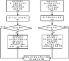
도 7(d)는 도 7(a)의 단계 706을 더 상세히 도시하는데, 여기서 깊이 값이 필요에 따라 스테레오스코픽 매칭을 이용하여 개선(refine)된다. 이 접근은 개선이 바람직함을 나타내는 조건을 검출하는데 응답하여 하나 이상의 깊이 값을 개선하기 위해 스테레오스코픽 매칭이 사용된다는 점에서 적응적(adaptive)이다. 스테레오스코픽 매칭은 프레임 내 픽셀의 부분집합에 대해서만 수행될 수 있다. 한 가지 접근에서, 픽셀이 구조광 패턴과 매칭될 수 없어 깊이 값이 널(null) 또는 디폴트 값일 때에 픽셀의 깊이 값의 개선이 바람직하다. 픽셀은 오클루젼, 음영(shadowing), 광 조건, 표면 질감 또는 기타 이유로 구조광 패턴에 매칭되지 않을 수 있다. 이 경우, 깊이 값이 이전에 획득되지 않은 경우에는 스테레오스코픽 매칭이 깊이 값을 제공할 수 있고, 또는 일부 경우에, 센서와 조명기 사이의 베이스라인 간격에 비해 더 큰 베이스라인으로 센서가 떨어져 있기 때문에 더 정확한 깊이 값을 제공할 수 있다. 예를 들어, 도 2, 6b 및 6d를 참조하라.FIG. 7D illustrates step 706 of FIG. 7A in more detail, where the depth value is refined using stereoscopic matching as needed. This approach is adaptive in that stereoscopic matching is used to improve one or more depth values in response to detecting a condition that an improvement is desired. Stereoscopic matching may only be performed on a subset of the pixels in the frame. In one approach, it is desirable to improve the depth value of a pixel when the pixel cannot match the structured light pattern so that the depth value is null or the default value. The pixels may not match the structured light pattern for occlusion, shadowing, light conditions, surface texture or other reasons. In this case, stereoscopic matching may provide a depth value if the depth value has not been previously obtained, or in some cases the sensor is separated by a larger baseline compared to the baseline spacing between the sensor and the fixture. More accurate depth values can be provided. See, for example, FIGS. 2, 6B and 6D.
다른 접근에서, 깊이 값이 문턱 거리를 초과하여 물체의 대응 점이 상대적으로 센서로부터 멀다는 것을 나타내는 때에, 픽셀의 깊이 값의 개선이 바람직하다. 이 경우, 센서 사이의 베이스라인이 각각의 센서와 조명기 사이의 베이스라인보다 큰 경우에 스테레오스코픽 매칭이 더 정확한 깊이 값을 제공할 수 있다.In another approach, an improvement in the depth value of the pixel is desirable when the depth value exceeds the threshold distance to indicate that the corresponding point of the object is relatively far from the sensor. In this case, stereoscopic matching can provide a more accurate depth value if the baseline between the sensors is larger than the baseline between each sensor and the illuminator.
개선에는, 이전에 깊이 값이 제공되지 않은 경우 깊이 값을 제공하는 것, 또는, 예를 들어, 비가중 평균, 가중 평균, 정확도 척도 및/또는 신뢰 척도가 관여되는 다른 접근에 기초하여 깊이 값을 병합하는 것이 관여될 수 있다. 또한, 개선은 깊이 값이 병합되기 전에 각각의 센서의 프레임에 대해 별도로 수행될 수 있다.The improvement may be based on providing a depth value if no depth value was previously provided, or based on another approach involving, for example, an unweighted average, weighted average, accuracy measure, and / or confidence measure. Merging may be involved. In addition, the improvement can be performed separately for the frame of each sensor before the depth values are merged.
개선이 바람직함을 나타내는 조건이 검출되는 픽셀에 대해서만 스테레오스코픽 매칭을 수행함으로써, 불필요한 처리를 피한다. 스테레오스코픽 매칭은 개선이 바람직함을 나타내는 조건이 검출되지 않은 픽셀에 대해 수행되지 않는다. 그러나, 프레임 내 하나 이상의 픽셀에 대해 개선이 바람직함을 나타내는 조건이 검출되는 때에 전체 프레임에 대해 스테레오스코픽 매칭을 수행하는 것도 가능하다. 한 가지 접근에서, 프레임 내 픽셀의 일부 중 최소 개수에 대해 개선이 표시되는 때에 전체 프레임에 대한 스테레오스코픽 매칭이 시작된다.By performing stereoscopic matching only on the pixels for which a condition indicating improvement is desired is avoided, unnecessary processing is avoided. Stereoscopic matching is not performed on pixels for which no condition was detected indicating that improvement is desired. However, it is also possible to perform stereoscopic matching over the entire frame when a condition is detected that indicates improvement is desirable for one or more pixels in the frame. In one approach, stereoscopic matching for the entire frame begins when an improvement is indicated for the minimum number of some of the pixels in the frame.
단계 760에서, 픽셀 데이터의 제1 프레임 내 각각의 픽셀에 대해, 조명 프레임 내의 대응 점을 결정하고, 단계 761에서, 대응하는 제1 구조광 깊이 맵을 제공한다. 결정 단계 762는 깊이 값의 개선이 표시되는지 여부를 결정한다. 기준은, 픽셀 데이터의 제1 프레임 내 각각의 픽셀에 대해 평가될 수 있고, 한 가지 접근에서, 픽셀과 연관된 깊이 값의 개선이 바람직한지 여부를 표시할 수 있다. 한 가지 접근에서, 관련 깊이 값이 사용가능하지 않거나 신뢰할 수 없을 때 개선이 바람직하다. 신뢰할 수 없음은 예를 들어 정확도 척도 및/또는 신뢰 척도에 기초할 수 있다. 신뢰 척도가 문턱 신뢰 척도를 초과하면, 깊이 값은 신뢰할 수 있는 것으로 간주될 수 있다. 또는, 정확도 척도가 문턱 정확도 척도를 초과하면, 깊이 값은 신뢰할 수 있는 것으로 간주될 수 있다. 다른 접근에서, 깊이 값이 신뢰할 수 있는 것으로 간주되기 위해 신뢰 척도 및 정확도 척도 모두가 각각의 문턱 수준을 초과하여야 한다.In
다른 접근에서, 깊이가 문턱 깊이를 넘는 때와 같이, 관련 깊이 값이 깊이가 상대적으로 멀다는 것을 나타내는 때에 개선이 바람직하다. 개선이 바람직하면, 단계 763는 픽셀 데이터의 제2 프레임 내 하나 이상의 픽셀에 대한 픽셀 데이터의 제1 프레임 내 하나 이상의 픽셀의 스테레오스코픽 매칭을 수행한다. 이는 픽셀 데이터의 제1 프레임의 하나 이상의 추가 깊이 값을 가져온다.In another approach, improvements are desirable when the associated depth value indicates that the depth is relatively far, such as when the depth exceeds the threshold depth. If an improvement is desired, step 763 performs stereoscopic matching of one or more pixels in the first frame of pixel data for one or more pixels in the second frame of pixel data. This results in one or more additional depth values of the first frame of pixel data.
유사하게, 픽셀 데이터의 제2 프레임에 대해, 단계 764에서, 픽셀 데이터의 제2 프레임 내 각각의 픽셀에 대해, 조명 프레임 내의 대응 점을 결정하고, 단계 765에서, 대응하는 제2 구조광 깊이 맵을 제공한다. 결정 단계 766은 깊이 값의 개선이 표시되는지 여부를 결정한다. 개선이 바람직하면, 단계 767은 픽셀 데이터의 제1 프레임 내 하나 이상의 픽셀에 대한 픽셀 데이터의 제2 프레임 내 하나 이상의 픽셀의 스테레오스코픽 매칭을 수행한다. 이는 픽셀 데이터의 제2 프레임의 하나 이상의 추가 깊이 값을 가져온다.Similarly, for a second frame of pixel data, in step 764, for each pixel in the second frame of pixel data, a corresponding point in the illumination frame is determined, and in step 765 the corresponding second structured light depth map To provide. Decision step 766 determines whether an improvement in the depth value is indicated. If an improvement is desired, step 767 performs stereoscopic matching of one or more pixels in the second frame of pixel data for one or more pixels in the first frame of pixel data. This results in one or more additional depth values of the second frame of pixel data.
단계 768은 픽셀 데이터의 제1 및 제2 프레임의 깊이 맵을 병합하는데, 여기서 병합은 단계 763 및/또는 767의 스테레오스코픽 매칭으로부터 획득되는 깊이 값을 포함한다. 병합은 비가중 평균, 가중 평균, 정확도 척도 및/또는 신뢰 척도가 관여되는 접근을 포함하여 다른 접근에 기초할 수 있다.Step 768 merges the depth maps of the first and second frames of pixel data, wherein the merging includes a depth value obtained from the stereoscopic matching of steps 763 and / or 767. Merging can be based on other approaches, including those involving weighted averages, weighted averages, accuracy measures, and / or confidence measures.
개선이 표시된 주어진 픽셀에 대해, 병합은 제1 구조광 깊이 맵으로부터의 깊이 값, 제2 구조광 깊이 맵으로부터의 깊이 값, 그리고 스테레오스코픽 매칭으로부터의 하나 이상의 깊이 값을 병합할 수 있음을 유의하라. 이 접근은 구조광 깊이 맵으로부터의 깊이 값을 폐기하고 스테레오스코픽 매칭으로부터의 깊이 값으로 대체하는 접근에 비해 더 신뢰할 수 있는 결과를 제공할 수 있다.Note that for a given pixel where an improvement is indicated, the merging can merge the depth value from the first structured light depth map, the depth value from the second structured light depth map, and one or more depth values from stereoscopic matching. . This approach can provide more reliable results than an approach that discards the depth value from the structured light depth map and replaces it with the depth value from stereoscopic matching.
도 7(e)는 도 7(a)의 단계 706에 대한 다른 접근을 더 상세히 도시하는데, 여기서 병합된 깊이 맵의 깊이 값은 필요에 따라 스테레오스코픽 매칭을 이용하여 개선된다. 이 접근에서, 구조광 패턴에 매칭함으로써 획득되는 깊이 맵의 병합은 개선 프로세스 전에 일어난다. 단계 760, 761, 764 및 765는 도 7(d)의 동일 번호의 단계와 동일하다. 단계 770는 구조광 깊이 맵을 병합한다. 병합은, 비가중 평균, 가중 평균, 정확도 척도 및/또는 신뢰도 척도가 관여되는 접근을 포함하여 다른 접근에 기초할 수 있다. 단계 771은 도 7(d)의 단계 762 및 766과 같고, 깊이 값의 개선이 표시되는지 여부를 결정하는 것을 포함한다.FIG. 7 (e) illustrates another approach to step 706 of FIG. 7 (a) in more detail, where the depth value of the merged depth map is improved using stereoscopic matching as needed. In this approach, the merging of the depth map obtained by matching the structured light pattern occurs before the improvement process.
기준은, 픽셀 데이터의 병합 깊이 맵 내 각각의 픽셀에 대해 평가될 수 있고, 한 가지 접근에서, 픽셀과 연관된 깊이 값의 개선이 바람직한지 여부를 표시할 수 있다. 한 가지 접근에서, 관련 깊이 값이 사용가능하지 않거나 신뢰할 수 없을 때 개선이 바람직하다. 신뢰할 수 없음은 예를 들어 정확도 척도 및/또는 신뢰 척도에 기초할 수 있다. 신뢰 척도가 문턱 신뢰 척도를 초과하면, 깊이 값은 신뢰할 수 있는 것으로 간주될 수 있다. 또는, 정확도 척도가 문턱 정확도 척도를 초과하면, 깊이 값은 신뢰할 수 있는 것으로 간주될 수 있다. 다른 접근에서, 깊이 값이 신뢰할 수 있는 것으로 간주되기 위해 신뢰 척도 및 정확도 척도 모두가 각각의 문턱 수준을 초과하여야 한다. 다른 접근에서, 깊이가 문턱 깊이를 넘는 때와 같이, 관련 깊이 값이 깊이가 상대적으로 멀다는 것을 나타내는 때에 개선이 바람직하다. 개선이 바람직하면, 단계 772 및/또는 773이 수행될 수 있다. 일부 경우에, 한 프레임 내 픽셀을 다른 프레임 내 픽셀에 매칭함으로써 한 방향의 스테레오스코픽 매칭이 수행되는 것으로 충분하다. 다른 경우에, 양 방향으로 스테레오스코픽 매칭이 수행될 수 있다. 단계 772는 픽셀 데이터의 제2 프레임 내 하나 이상의 픽셀에 대한 픽셀 데이터의 제1 프레임 내 하나 이상의 픽셀의 스테레오스코픽 매칭을 수행한다. 이는 픽셀 데이터의 제1 프레임의 하나 이상의 추가 깊이 값을 가져온다. 단계 773은 픽셀 데이터의 제1 프레임 내 하나 이상의 픽셀에 대한 픽셀 데이터의 제2 프레임 내 하나 이상의 픽셀의 스테레오스코픽 매칭을 수행한다. 이는 픽셀 데이터의 제2 프레임의 하나 이상의 추가 깊이 값을 가져온다. The criterion may be evaluated for each pixel in the merge depth map of the pixel data and, in one approach, may indicate whether an improvement in the depth value associated with the pixel is desired. In one approach, improvement is desirable when the relevant depth value is not available or reliable. Unreliability can be based on, for example, an accuracy measure and / or a confidence measure. If the confidence measure exceeds the threshold confidence measure, the depth value may be considered reliable. Or, if the accuracy measure exceeds the threshold accuracy measure, the depth value may be considered reliable. In another approach, both the confidence measure and the accuracy measure must exceed each threshold level in order for the depth value to be considered reliable. In another approach, improvements are desirable when the associated depth value indicates that the depth is relatively far, such as when the depth exceeds the threshold depth. If improvements are desired, steps 772 and / or 773 may be performed. In some cases, it is sufficient that stereoscopic matching in one direction is performed by matching pixels in one frame to pixels in another frame. In other cases, stereoscopic matching may be performed in both directions. Step 772 performs stereoscopic matching of one or more pixels in the first frame of pixel data for one or more pixels in the second frame of pixel data. This results in one or more additional depth values of the first frame of pixel data. Step 773 performs stereoscopic matching of one or more pixels in a second frame of pixel data for one or more pixels in a first frame of pixel data. This results in one or more additional depth values of the second frame of pixel data.
단계 774는 스테레오스코픽 매칭이 수행된 하나 이상의 선택된 픽셀에 대해 단계 770의 병합된 깊이 맵을 개선한다. 개선에는, 비가중 평균, 가중 평균, 정확도 척도 및/또는 신뢰도 척도가 관여되는 접근을 포함하여 다른 접근에 기초한 깊이 값 병합이 관여될 수 있다.Step 774 improves the merged depth map of
단계 771에서 개선이 바람직하지 않으면, 프로세스는 단계 775에서 끝난다.If no improvement is desired at
도 8은 도 7(a)의 단계 708에 제시된 제어 입력을 이용하여 사람 타겟을 추적하기 위한 예시적인 방법을 도시한다. 언급된 바와 같이, 깊이 카메라 시스템은 제스터와 같은 사용자의 움직임을 추적하는데 사용될 수 있다. 움직임은 애플리케이션에서 제어 입력으로서 처리될 수 있다. 예를 들어, 이는 도 1에 도시된 바와 같이 아바타가 사용자를 나타내는 경우에 디스플레이 상의 아바타의 위치를 업데이트하는 것, 사용자 인터페이스(UI)에서 메뉴 아이템을 선택하는 것 또는 기타 많은 가능한 동작을 포함할 수 있다.FIG. 8 illustrates an example method for tracking a human target using the control input presented in step 708 of FIG. 7A. As mentioned, the depth camera system can be used to track the movement of a user, such as a zester. The movement can be treated as control input in the application. For example, this may include updating the position of the avatar on the display, selecting a menu item in the user interface (UI), or many other possible actions when the avatar represents a user, as shown in FIG. 1. have.
예시적인 방법은, 예를 들어, 도 2-4와 관련하여 논의된 바와 같은 깊이 카메라 시스템(20) 및/또는 컴퓨팅 환경(12, 100 또는 420)을 이용하여 구현될 수 있다. 골격 모델, 매시 휴먼(mesh human) 모델 또는 기타 여하한 사람의 적당한 표현과 같은 모델을 생성하기 위해 하나 이상의 사람 타겟이 스캐닝될 수 있다. 골격 모델에서, 각각의 신체 부분은 골격 모델의 관절과 골격을 정의하는 수학적 벡터로 특징지워질 수 있다. 신체 부분은 관절에서 서로에 대해 움직일 수 있다.The example method may be implemented using, for example,
그러면 모델은 컴퓨팅 환경에 의해 실행되는 애플리케이션과 상호작용하는데 사용될 수 있다. 모델을 생성하기 위한 스캐닝은 애플리케이션이 시작 또는 론칭되는 때에, 또는 스캐닝되는 사람의 애플리케이션에 의해 제어되는 다른 시간에 일어날 수 있다.The model can then be used to interact with the application running by the computing environment. Scanning to generate the model may occur when the application is started or launched, or at other times controlled by the application of the person being scanned.
사용자의 물리적 움직임 또는 모션이 애플리케이션의 파라미터를 조정 및/또는 제어하는 실시간 사용자 인터페이스로서 동작하도록 추적될 수 있는 골격 모델을 생성하기 위해 사람이 스캐닝될 수 있다. 예를 들어, 사람의 추적된 움직임은, 전자 롤-플레잉 게임에서 아바타나 기타 스크린 상의 캐릭터를 움직이거나, 전자 레이싱 게임에서 스크린 상의 차량을 제어하거나, 가상 환경에서 건물이나 물체의 조직을 제어하거나, 애플리케이션의 여하한 기타 적당한 제어를 수행하는데 사용될 수 있다. A person can be scanned to generate a skeletal model that can be tracked so that the user's physical movement or motion acts as a real time user interface to adjust and / or control the parameters of the application. For example, a person's tracked movements can move an avatar or other character on the screen in an electronic role-playing game, control a vehicle on the screen in an electronic racing game, control the organization of a building or object in a virtual environment, It can be used to perform any other appropriate control of the application.
일 실시형태에 따르면, 단계 800에서, 예를 들어 깊이 카메라 시스템으로부터 깊이 정보가 수신된다. 깊이 카메라 시스템은 하나 이상의 타겟을 포함할 수 있는 시야를 캡처 또는 관찰할 수 있다. 깊이 정보는 복수의 관찰된 픽셀을 갖는 깊이 이미지 또는 맵을 포함할 수 있는데, 여기서 각각의 관찰된 픽셀은 논의된 바와 같이 관찰된 깊이 값을 갖는다.According to one embodiment, at step 800, depth information is received, for example, from a depth camera system. The depth camera system may capture or observe a field of view that may include one or more targets. The depth information may comprise a depth image or map having a plurality of observed pixels, where each observed pixel has an observed depth value as discussed.
깊이 이미지는 더 낮은 처리 해상도로 다운샘플링될 수 있어서 더 쉽게 사용되고 더 적은 연산 오버헤드로 처리될 수 있다. 또한, 하나 이상의 고분산(high-variance) 및/또는 잡음이 많은(noisy) 깊이 값이 깊이 이미지로부터 제거되거나 및/또는 평판화(smooth)될 수 있고; 누락 및/또는 제거된 깊이 정보의 부분이 채워지거나 및/또는 재구성될 수 있고; 및/또는 깊이 정보가 골격 모델(도 9 참조)과 같은 모델을 생성하는데 사용될 수 있도록 여하한 기타 적당한 처리가 수신된 깊이 정보에 대해 수행될 수 있다.Depth images can be downsampled to lower processing resolutions so that they can be used more easily and processed with less computational overhead. In addition, one or more high-variance and / or noisy depth values may be removed from the depth image and / or smoothed; Portions of the missing and / or removed depth information may be filled and / or reconstructed; And / or any other suitable processing may be performed on the received depth information such that the depth information can be used to generate a model such as a skeleton model (see FIG. 9).
단계 802는 사람 타겟이 깊이 이미지를 포함하는지 여부를 결정한다. 이는 깊이 이미지가 사람 타겟을 포함하는지를 판정하기 위해 각각의 타겟 또는 물체를 패턴에 비교하여 깊이 이미지 내 각각의 타겟이나 물체를 플러드 필링(flood filling)하는 것을 포함할 수 있다. 예를 들어, 상술한 바와 같이 타겟 또는 물체를 정의할 수 있는 에지(edge)를 결정하기 위해 선택된 영역 내의 픽셀의 다양한 깊이 값 또는 깊이 이미지의 점이 비교될 수 있다. Z 층의 가능한 Z 값이 결정된 에지에 기초하여 플러드 필링될 수 있다. 예를 들어, 결정된 에지와 관련된 픽셀 및 에지 내 영역의 픽셀은, 패턴과 비교될 수 있는 캡처된 영역 내 타겟 또는 물체를 정의하기 위해 서로 연관될 수 있는데, 이는 아래에서 더 상세히 설명한다.Step 802 determines whether the human target includes a depth image. This may include flood filling each target or object in the depth image by comparing each target or object to a pattern to determine whether the depth image includes a human target. For example, various depth values of the pixels within a selected area or points in the depth image may be compared to determine an edge that may define a target or object as described above. Possible Z values of the Z layer can be flood filled based on the determined edges. For example, the pixels associated with the determined edge and the pixels in the area within the edge may be associated with each other to define a target or object in the captured area that can be compared to the pattern, as described in more detail below.
결정 단계 804에서 깊이 이미지가 사람 타겟을 포함하면, 단계 806이 수행된다. 결정 단계 804가 부(false)이면, 추가의 깊이 정보가 단계 800에서 수신된다.If the depth image includes a human target at
각각의 타겟 또는 물체가 비교되는 패턴은, 총체적으로 보통의 신체를 정의하는 변수의 세트를 갖는 하나 이상의 데이터 구조를 포함할 수 있다. 예를 들어, 시야 내의 사람 타겟 및 사람이 아닌 타겟(non-human target)의 픽셀과 연관된 정보는 사람 타겟을 식별하기 위해 변수와 비교될 수 있다. 일 실시형태에서, 세트 내의 각각의 변수는 신체 부분에 기초하여 가중될 수 있다. 예를 들어, 패턴 내의 머리 및/또는 어깨와 같은 다양한 신체 부분은 다리와 같은 같은 신체 부분에 비해 더 클 수 있는 연관 가중치를 가질 수 있다. 일 실시형태에 따르면, 타겟이 사람인지 여부와 어떤 타겟이 사람인지를 결정하기 위해 타겟을 변수와 비교하는 때에 가중치가 사용될 수 있다. 예를 들어, 큰 가중치를 갖는 타겟 및 변수 사이의 매칭은 작은 가중치를 갖는 매칭에 비해 타겟이 사람일 가능성이 더 높다. The pattern with which each target or object is compared may comprise one or more data structures having a set of variables that collectively define an ordinary body. For example, information associated with pixels of human targets and non-human targets in the field of view may be compared to variables to identify human targets. In one embodiment, each variable in the set may be weighted based on the body part. For example, various body parts, such as the head and / or shoulders, in the pattern may have an associative weight that may be larger than body parts, such as legs. According to one embodiment, weights may be used when comparing a target with a variable to determine whether the target is a person and which target is a person. For example, a match between a variable having a large weight and a variable is more likely that the target is a person than a match having a small weight.
단계 806은 신체 부분에 대해 사람 타겟을 스캐닝하는 것을 포함한다. 사람의 정확한 모델을 제공하기 위해, 사람 타겟은 사람의 하나 이상의 신체 부분과 연관된 길이, 폭 등과 같은 척도를 제공하기 위해 스캐닝될 수 있다. 예시적인 실시형태에서, 사람 타겟이 고립(isolate)될 수 있고 하나 이상의 신체 부분에 대한 스캐닝을 위해 사람 타겟의 비트마스크(bitmask)가 생성될 수 있다. 비트마스크는, 예를 들어, 사람 타겟이 캡처 영역 요소 내 다른 타겟이나 물체와 분리될 수 있도록 사람 타겟을 플러드 필링함으로써 생성될 수 있다. 그러면 비트마스크는 사람 타겟의 골격 모델, 메시 휴먼 모델 등과 같은 모델을 생성하기 위해 하나 이상의 신체 부분에 대하여 분석될 수 있다. 예를 들어, 일 실시형태에 따르면, 스캐닝된 비트마스크에 의해 결정된 측정 값은 골격 모델에서 하나 이상의 관절을 정의하기 위해 사용될 수 있다. 하나 이상의 관절이 사람의 신체 부분에 대응할 수 있는 하나 이상의 뼈를 정의하는데 사용될 수 있다. Step 806 includes scanning the human target for the body part. To provide an accurate model of a person, a human target may be scanned to provide measures such as length, width, etc., associated with one or more body parts of the person. In an example embodiment, the human target can be isolated and a bitmask of the human target can be generated for scanning one or more body parts. The bitmask can be generated, for example, by flood peeling the human target so that the human target can be separated from other targets or objects in the capture area element. The bitmask can then be analyzed for one or more body parts to create a model, such as a skeletal model, a mesh human model, or the like of a human target. For example, according to one embodiment, the measured value determined by the scanned bitmask can be used to define one or more joints in the skeletal model. One or more joints may be used to define one or more bones that may correspond to a body part of a person.
예를 들어, 사람 타겟의 비트마스크의 정점(top)은 정수리(top of head) 위치에 연관될 수 있다. 정수리를 결정한 후에, 비트마스크가 아래쪽으로 스캐닝되고 그래서 목의 위치, 어깨의 위치 등을 결정할 수 있다. 예를 들어, 스캐닝되고 있는 위치에서, 비트마스크의 폭은, 예를 들어, 목, 어깨 등과 연관되는 통상의 폭의 문턱 값에 비교될 수 있다. 다른 실시형태에서, 스캐닝되고 비트마스크 내 신체 부분과 연관된 이전 위치로부터의 거리가 목, 어깨 등의 위치를 결정하는데 사용될 수 있다. 다리, 발 등의 일부 신체 부분은, 예를 들어, 다른 신체 부분의 위치에 기초하여 계산될 수 있다. 신체 부분의 값을 결정하는 때에, 신체 부분의 측정 값을 포함하는 데이터 구조가 생성된다. 데이터 구조는 깊이 카메라 시스템에 의해 다른 점에서 제공되는 다수의 깊이 이미지로부터 평균된 스캐닝 결과를 포함할 수 있다. For example, the top of the bitmask of the human target may be associated with a top of head position. After determining the crown, the bitmask is scanned downward so that the position of the neck, the position of the shoulder, and the like can be determined. For example, at the location being scanned, the width of the bitmask can be compared to a threshold of a typical width associated with, for example, the neck, shoulders, and the like. In another embodiment, the distance from the previous location that is scanned and associated with the body part in the bitmask can be used to determine the location of the neck, shoulder, and the like. Some body parts, such as legs, feet, etc. may be calculated based on the position of other body parts, for example. In determining the value of the body part, a data structure is generated that includes the measured values of the body part. The data structure may include scanning results averaged from multiple depth images provided at different points by the depth camera system.
단계 808는 사람 타겟의 모델을 생성하는 것을 포함한다. 일 실시형태에서, 스캐닝된 비트마스크에 의해 결정되는 측정 값은 골격 모델에서 하나 이상의 관절을 정의하는데 사용될 수 있다. 하나 이상의 관절은 사람의 신체 부분에 대응하는 하나 이상의 뼈를 정의하는데 사용될 수 있다.Step 808 includes generating a model of a human target. In one embodiment, the measurement value determined by the scanned bitmask can be used to define one or more joints in the skeletal model. One or more joints may be used to define one or more bones that correspond to body parts of a person.
더 정확한 골격 모델을 생성하기 위하여 관절이 사람의 신체 부분과 관절 사이의 통상의 거리 범위 내가 될 때까지 하나 이상의 관절이 조정될 수 있다. 모델은, 예를 들어, 사람 타겟과 연관된 키에 기초하여 더 조정될 수 있다.One or more joints may be adjusted until the joint is within the normal range of distance between the body part of the person and the joint to produce a more accurate skeletal model. The model may be further adjusted based on, for example, the key associated with the person target.
단계 810에서, 모델은 사람의 위치를 초당 수회 업데이트함으로써 추적된다. 사용자가 물리적 공간에서 움직임에 따라, 골격 모델이 사람을 나타내도록 골격 모델을 조정하기 위해 깊이 카메라 시스템으로부터의 정보가 사용된다. 특히, 물리적 공간에서의 사람 타겟의 포즈에 더 가깝게 대응하는 포즈로 골격 모델을 조정하기 위해 골격 모델의 하나 이상의 수력(force-receiving) 측면에 하나 이상의 힘이 가해질 수 있다. In step 810, the model is tracked by updating a person's location several times per second. As the user moves in physical space, information from the depth camera system is used to adjust the skeletal model such that the skeletal model represents a person. In particular, one or more forces may be applied to one or more force-receiving aspects of the skeletal model to adjust the skeletal model to a pose that corresponds more closely to the pose of the human target in physical space.
일반적으로, 사람의 움직임을 추적하기 위한 여하한 알려진 기술이 사용될 수 있다.In general, any known technique for tracking the movement of a person can be used.
도 9는 도 8의 단계 808에서 제시된 사람 타겟의 예시적 모델을 도시한다. 모델(900)은 도 1의 z 방향으로 깊이 카메라를 마주하고 있어서, 도시된 단면은 x-y 평면에 있다. 모델은, 예를 들어, 정수리(902), 머리 아래 또는 턱(913), 오른쪽 어깨(904), 오른쪽 팔꿈치(906), 오른쪽 손목(908) 및 손끝 영역으로 표시되는 오른손(910)과 같은 다수의 기준점을 포함한다. 오른쪽과 왼쪽은 카메라를 바라보는 사용자의 입장에서 정의된다. 모델은 또한 왼쪽 어깨(914), 왼쪽 팔꿈치(916), 왼쪽 손목(918) 및 왼손(920)을 포함한다. 허리 영역(922)도, 오른쪽 엉덩이(924), 오른쪽 무릎(926), 오른발(928), 왼쪽 엉덩이(930), 왼쪽 무릎(932) 및 왼발(934)과 함께 도시된다. 어깨선(912)은 어깨(904와 914) 사이의 통상 수평인 선이다. 점(922와 913) 사이에서 연장하는 상체 중심선(925)도 도시된다.9 illustrates an example model of a human target presented at
따라서, 많은 장점을 갖는 깊이 카메라 시스템이 제공됨을 알 수 있다. 하나의 장점은 오클루젼 감소이다. 더 넓은 베이스라인이 사용되므로, 하나의 센서는 다른 센서에게 가려진 정보를 볼 수 있다. 2개의 깊이 맵을 융합하는 것은 단일 센서에 의해 산출되는 맵에 비해 더 관찰가능한 물체를 갖는 3D 이미지를 산출한다. 다른 장점은 감소된 음영 효과이다. 구조광 방법은 내재적으로 센서에게는 보이지만 광원에게는 보이지 않는 위치에서 음영 효과를 만든다. 이들 영역에서 스테레오스코픽 매칭을 적용함으로서, 이 효과가 감소될 수 있다. 다른 장점은 외부 광에 대한 강인성이다. 외부 광이 구조광 카메라를 혼란시켜서 유효한 결과를 산출할 수 없는 많은 시나리오가 있다. 이들 경우에, 스테레오스코픽 데이터가 추가의 척도로서 획득되는데, 실제로 외부 광이 거리를 측정하는데 있어서 이를 도울 수 있기 때문이다. 외부 광은 동일한 장면에서 바라보는 동일한 카메라로부터 올 수 있음을 유의하라. 달리 말하면, 동일한 장면을 바라보는 2 이상의 제안된 카메라를 동작하는 것이 가능하다. 이는, 하나의 카메라에 의해 산출된 광 패턴이 다른 카메라가 패턴을 적절하게 매칭하는데 혼란을 줄 수 있더라도, 여전히 스테레오스코픽 매칭은 성공할 가능성이 높기 때문이다. 다른 장점은, 제안된 구성을 이용하여, 2개의 센서가 더 넓은 베이스라인을 갖는다는 사실 때문에 먼 거리에서 더 높은 정확도를 달성할 수 있다는 것이다. 구조광과 스테레오스코픽 층정 정확도는 모두 센서/프로젝터 사이의 거리에 크게 의존한다. Thus, it can be seen that a depth camera system having many advantages is provided. One advantage is occlusion reduction. Since a wider baseline is used, one sensor can see information hidden by the other. Fusing two depth maps yields a 3D image with a more observable object compared to the map produced by a single sensor. Another advantage is the reduced shading effect. The structured light method inherently produces a shading effect at locations that are visible to the sensor but not to the light source. By applying stereoscopic matching in these areas, this effect can be reduced. Another advantage is the robustness to external light. There are many scenarios in which external light can disrupt the structured light cameras and yield no valid results. In these cases, stereoscopic data is obtained as an additional measure, because in practice external light can help in measuring the distance. Note that the external light can come from the same camera looking in the same scene. In other words, it is possible to operate two or more proposed cameras looking at the same scene. This is because, even if the light pattern produced by one camera may confuse other cameras in matching the pattern properly, stereoscopic matching is still likely to succeed. Another advantage is that with the proposed configuration, higher accuracy can be achieved over long distances due to the fact that the two sensors have a wider baseline. Both structured light and stereoscopic stratification accuracy are highly dependent on the distance between the sensor / projector.
본 기술의 이상의 상세한 설명은 예시와 설명의 목적으로 제시되었다. 이는 망라적인 것이 아니고 정확히 개시된 형태로 본 기술을 제한하려는 것도 아니다. 위의 교시에 비추어 많은 수정과 변경이 가능하다. 설명된 실시형태는, 본 기술의 원리 및 그의 실제적 적용을 가장 잘 설명하여 당업자가 생각하는 구체적인 용도에 맞도록 다양한 실시형태에서 다양한 변경으로 본 기술을 가장 잘 이용할 수 있게 하기 위해서 선택되었다. 본 기술의 범위는 첨부된 청구범위에 의해 정의되도록 한 것이다.The foregoing detailed description of the technology has been presented for purposes of illustration and description. It is not intended to be exhaustive or to limit the technology to the precise form disclosed. Many modifications and variations are possible in light of the above teaching. The described embodiments were chosen to best explain the principles of the present technology and its practical application, so as to best utilize the present technology with various modifications in various embodiments to suit the specific uses contemplated by those skilled in the art. It is intended that the scope of the technology be defined by the claims appended hereto.
Claims (15)
픽셀 데이터의 제1 프레임을 획득하기 위해 상기 물체로부터 반사된 광을 감지하는 제1 센서-상기 제1 센서는 더 짧은 범위 이미징에 최적화됨-와,
픽셀 데이터의 제2 프레임을 획득하기 위해 상기 물체로부터 반사된 광을 감지하는 제2 센서-상기 제2 센서는 더 긴 범위 이미징에 최적화됨-와,
픽셀 데이터의 상기 제1 프레임을 상기 구조광의 상기 패턴과 비교함으로써 상기 물체의 제1 구조광 깊이 맵을 도출하고, 픽셀 데이터의 상기 제2 프레임을 상기 구조광의 상기 패턴과 비교함으로써 상기 물체의 제2 구조광 깊이 맵을 도출하고, 상기 제1 및 제2 구조광 깊이 맵에 기초하는 병합된 깊이 맵을 도출하는, 적어도 하나의 제어 회로를 포함하는
깊이 카메라 시스템.
Illuminators that illuminate objects in the field of vision in a pattern of structured light;
A first sensor for sensing light reflected from the object to obtain a first frame of pixel data, the first sensor being optimized for shorter range imaging;
A second sensor for sensing light reflected from the object to obtain a second frame of pixel data, the second sensor being optimized for longer range imaging;
Comparing the first frame of pixel data with the pattern of the structured light to derive a first structured light depth map of the object, and comparing the second frame of pixel data with the pattern of the structured light At least one control circuitry for deriving a structured light depth map and for deriving a merged depth map based on the first and second structured light depth maps;
Depth camera system.
상기 제1 센서와 상기 조명기 사이의 베이스라인 거리(BL1)는 상기 제2 센서와 상기 조명기 사이의 베이스라인 거리(BL2)보다 작은
깊이 카메라 시스템.The method of claim 1,
The baseline distance BL1 between the first sensor and the illuminator is smaller than the baseline distance BL2 between the second sensor and the illuminator.
Depth camera system.
상기 제1 센서의 노출 시간은 상기 제2 센서의 노출 시간보다 짧은
깊이 카메라 시스템.
3. The method of claim 2,
The exposure time of the first sensor is shorter than the exposure time of the second sensor.
Depth camera system.
상기 제1 센서의 감도는 상기 제2 센서의 감도보다 작은
깊이 카메라 시스템.
3. The method of claim 2,
The sensitivity of the first sensor is less than the sensitivity of the second sensor
Depth camera system.
상기 제1 센서의 공간 해상도는 상기 제2 센서의 공간 해상도보다 작은
깊이 카메라 시스템.
3. The method of claim 2,
The spatial resolution of the first sensor is less than the spatial resolution of the second sensor
Depth camera system.
상기 제2 구조광 깊이 맵은 깊이 값을 포함하고,
상기 병합된 깊이 맵을 도출하는데 있어서, 상기 제2 구조광 깊이 맵의 상기 깊이 값은 상기 제1 구조광 깊이 맵의 깊이 값보다 더 강하게 가중되는
깊이 카메라 시스템.
The method of claim 1,
The second structured light depth map includes a depth value,
In deriving the merged depth map, the depth value of the second structured light depth map is weighted more strongly than the depth value of the first structured light depth map.
Depth camera system.
상기 적어도 하나의 제어 회로는 상기 물체의 적어도 하나의 스테레오스코픽 깊이 맵에 기초하여 상기 병합된 깊이 맵을 도출하고,
상기 적어도 하나의 제어 회로는, (i)픽셀 데이터의 상기 제2 프레임에 픽셀 데이터의 상기 제1 프레임을 스테레오스코픽 매칭하는 것과 (ii)픽셀 데이터의 상기 제1 프레임에 픽셀 데이터의 상기 제2 프레임을 스테레오스코픽 매칭하는 것 중적어도 하나에 의해 상기 적어도 하나의 스테레오스코픽 깊이 맵을 도출하는
깊이 카메라 시스템.
The method of claim 1,
The at least one control circuit derives the merged depth map based on at least one stereoscopic depth map of the object,
The at least one control circuit comprises (i) stereoscopic matching of the first frame of pixel data to the second frame of pixel data and (ii) the second frame of pixel data to the first frame of pixel data. Deriving the at least one stereoscopic depth map by at least one of stereoscopic matching
Depth camera system.
상기 제1 및 제2 구조광 깊이 맵과 상기 적어도 하나의 스테레오스코픽 깊이 맵은 깊이 값을 포함하고,
상기 적어도 하나의 제어 회로는 상기 물체의 상기 제1 구조광 깊이 맵의 상기 깊이 값에 제1 세트의 가중치를 할당하고, 상기 물체의 상기 제2 구조광 깊이 맵의 상기 깊이 값에 제2 세트의 가중치를 할당하며, 상기 물체의 상기 스테레오스코픽 깊이 맵의 상기 깊이 값에 제3 세트의 가중치를 할당하고, 상기 제1, 제2 및 제3 세트의 가중치에 기초하여 상기 병합된 깊이 맵을 도출하는
깊이 카메라 시스템.
The method of claim 7, wherein
The first and second structured light depth maps and the at least one stereoscopic depth map include depth values,
The at least one control circuit assigns a first set of weights to the depth value of the first structured light depth map of the object, wherein the at least one control circuit assigns a second set of weights to the depth value of the second structured light depth map of the object. Assigning a weight, assigning a third set of weights to the depth values of the stereoscopic depth map of the object, and deriving the merged depth map based on the first, second, and third sets of weights.
Depth camera system.
상기 제1 세트의 가중치는 상기 제1 센서와 상기 조명기 사이의 베이스라인 거리에 기초하여 할당되고,
상기 제2 세트의 가중치는 상기 제2 센서와 상기 조명기 사이의 베이스라인 거리에 기초하여 할당되며,
상기 제3 세트의 가중치는 상기 제1 및 제2 센서 사이의 베이스라인 거리에 기초하여 할당되는
깊이 카메라 시스템.
The method of claim 8,
The first set of weights is assigned based on a baseline distance between the first sensor and the illuminator,
The second set of weights is assigned based on a baseline distance between the second sensor and the illuminator,
The third set of weights is assigned based on a baseline distance between the first and second sensors.
Depth camera system.
구조광의 패턴으로 시야 내 물체를 조명하는 단계와,
제1 센서에서, 픽셀 데이터의 제1 프레임을 획득하기 위해 상기 물체로부터 반사된 광을 감지하는 단계와,
제2 센서에서, 픽셀 데이터의 제2 프레임을 획득하기 위해 상기 물체로부터 반사된 광을 감지하는 단계와,
픽셀 데이터의 상기 제1 프레임을 상기 구조광의 상기 패턴과 비교함으로써 상기 물체의 제1 구조광 깊이 맵을 도출하는 단계-상기 제1 구조광 깊이 맵은 픽셀 데이터의 상기 제1 프레임의 픽셀에 대한 깊이 값을 포함함-와,
픽셀 데이터의 상기 제2 프레임을 상기 구조광의 상기 패턴과 비교함으로써 상기 물체의 제2 구조광 깊이 맵을 도출하는 단계-상기 제2 구조광 깊이 맵은 픽셀 데이터의 상기 제2 프레임의 픽셀에 대한 깊이 값을 포함-와,
픽셀 데이터 맵의 상기 제1 프레임의 하나 이상의 픽셀의 상기 깊이 값의 개선(refinement)이 희망되는지 여부를 결정하는 단계와,
상기 개선이 희망되는 경우, 픽셀 데이터의 상기 제1 프레임의 상기 하나 이상의 픽셀을 픽셀 데이터의 상기 제2 프레임의 하나 이상의 픽셀에 스테레오스코픽 매칭하는 것을 수행하는 단계를 포함하는
이미지 데이터 처리 방법.
A method of processing image data in a depth camera system,
Illuminating an object in the field of view with a pattern of structured light;
Sensing, at a first sensor, light reflected from the object to obtain a first frame of pixel data;
Sensing, at a second sensor, light reflected from the object to obtain a second frame of pixel data;
Deriving a first structured light depth map of the object by comparing the first frame of pixel data with the pattern of structured light, wherein the first structured light depth map is a depth for a pixel of the first frame of pixel data. Contains a value-and,
Deriving a second structured light depth map of the object by comparing the second frame of pixel data with the pattern of structured light, wherein the second structured light depth map is a depth for a pixel of the second frame of pixel data. Contains the value-and,
Determining whether refinement of the depth value of one or more pixels of the first frame of a pixel data map is desired;
If the improvement is desired, performing stereoscopic matching of the one or more pixels of the first frame of pixel data to one or more pixels of the second frame of pixel data.
How image data is processed.
픽셀 데이터의 상기 제1 프레임을 상기 구조광의 상기 패턴과 비교하는데 있어 픽셀 데이터의 상기 제1 프레임의 상기 하나 이상의 픽셀이 구조광의 상기 패턴에 성공적으로 매칭되지 않은 때에 상기 개선이 희망되는
이미지 데이터 처리 방법.
11. The method of claim 10,
The improvement is desired when comparing the first frame of pixel data with the pattern of structured light when the one or more pixels of the first frame of pixel data do not successfully match the pattern of structured light.
How image data is processed.
상기 개선은 상기 깊이 값이 문턱 거리를 초과하는 때에 희망되는
이미지 데이터 처리 방법.
11. The method of claim 10,
The improvement is desired when the depth value exceeds the threshold distance
How image data is processed.
상기 제1 및 제2 센서 사이의 베이스라인 거리(BL1+BL2)는 상기 제1 센서와 조명기 사이의 베이스라인 거리(BL1)보다 크고, 상기 제2 센서와 상기 조명기 사이의 베이스라인 거리(BL2)보다 큰
이미지 데이터 처리 방법.
11. The method of claim 10,
The baseline distance BL1 + BL2 between the first and second sensors is greater than the baseline distance BL1 between the first sensor and the illuminator, and the baseline distance BL2 between the second sensor and the illuminator Greater than
How image data is processed.
상기 스테레오스코픽 매칭은 상기 개선이 희망되는 픽셀 데이터의 상기 제1 프레임의 상기 하나 이상의 픽셀에 대해 수행되지만, 상기 개선이 희망되지 않는 픽셀 데이터의 상기 제1 프레임의 하나 이상의 다른 픽셀에 대해서는 수행되지 않는
이미지 데이터 처리 방법.
11. The method of claim 10,
The stereoscopic matching is performed on the one or more pixels of the first frame of pixel data for which the improvement is desired, but not for one or more other pixels of the first frame of pixel data for which the improvement is not desired.
How image data is processed.
상기 개선이 희망되는 경우, 상기 스테레오스코픽 매칭 및 상기 제1 및 제2 구조광 깊이 맵에 기초하여 병합 깊이 맵을 제공하는 단계를 더 포함하는
이미지 데이터 처리 방법.11. The method of claim 10,
If the improvement is desired, further comprising providing a merge depth map based on the stereoscopic matching and the first and second structured light depth maps.
How image data is processed.
Applications Claiming Priority (3)
| Application Number | Priority Date | Filing Date | Title |
|---|---|---|---|
| US12/877,595 | 2010-09-08 | ||
| US12/877,595 US20120056982A1 (en) | 2010-09-08 | 2010-09-08 | Depth camera based on structured light and stereo vision |
| PCT/US2011/046139 WO2012033578A1 (en) | 2010-09-08 | 2011-08-01 | Depth camera based on structured light and stereo vision |
Publications (1)
| Publication Number | Publication Date |
|---|---|
| KR20140019765A true KR20140019765A (en) | 2014-02-17 |
Family
ID=45770424
Family Applications (1)
| Application Number | Title | Priority Date | Filing Date |
|---|---|---|---|
| KR1020137005894A KR20140019765A (en) | 2010-09-08 | 2011-08-01 | Depth camera based on structured light and stereo vision |
Country Status (7)
| Country | Link |
|---|---|
| US (1) | US20120056982A1 (en) |
| EP (1) | EP2614405A4 (en) |
| JP (1) | JP5865910B2 (en) |
| KR (1) | KR20140019765A (en) |
| CN (1) | CN102385237B (en) |
| CA (1) | CA2809240A1 (en) |
| WO (1) | WO2012033578A1 (en) |
Cited By (11)
| Publication number | Priority date | Publication date | Assignee | Title |
|---|---|---|---|---|
| KR20150090679A (en) * | 2014-01-29 | 2015-08-06 | 엘지이노텍 주식회사 | Apparatus and method for detecting depth map |
| KR20150101749A (en) * | 2014-02-27 | 2015-09-04 | 엘지전자 주식회사 | Device for estimating three-dimensional shape of object and method thereof |
| KR20150124208A (en) * | 2014-04-28 | 2015-11-05 | (주)에프엑스기어 | Apparatus and method for physical simulation of cloth for virtual fitting based on augmented reality |
| KR20160015662A (en) * | 2014-07-31 | 2016-02-15 | 한국전자통신연구원 | Method of stereo matching and apparatus for performing the method |
| WO2017126711A1 (en) * | 2016-01-19 | 2017-07-27 | 전자부품연구원 | Illumination control method and system for optimal depth recognition of stereoscopic camera |
| WO2017195984A1 (en) * | 2016-05-13 | 2017-11-16 | (주)칼리온 | 3d scanning device and method |
| KR20170129882A (en) * | 2015-03-22 | 2017-11-27 | 페이스북, 인크. | Depth mapping of head-mounted displays using stereo cameras and structured light |
| KR20180019606A (en) * | 2015-06-25 | 2018-02-26 | 퀄컴 인코포레이티드 | Methods and apparatus for performing exposure estimation using a time-of-flight sensor |
| KR20190127870A (en) * | 2017-03-21 | 2019-11-13 | 매직 립, 인코포레이티드 | Depth Sensing Technology for Virtual, Augmented, and Mixed Reality Systems |
| WO2021061241A1 (en) * | 2019-09-27 | 2021-04-01 | Intel Corporation | Contextual memory map representation for 3d reconstruction |
| WO2022025458A1 (en) * | 2020-07-29 | 2022-02-03 | 삼성전자주식회사 | Electronic device and method for controlling same |
Families Citing this family (331)
| Publication number | Priority date | Publication date | Assignee | Title |
|---|---|---|---|---|
| US8121361B2 (en) | 2006-05-19 | 2012-02-21 | The Queen's Medical Center | Motion tracking system for real time adaptive imaging and spectroscopy |
| US11792538B2 (en) | 2008-05-20 | 2023-10-17 | Adeia Imaging Llc | Capturing and processing of images including occlusions focused on an image sensor by a lens stack array |
| EP4336447A1 (en) | 2008-05-20 | 2024-03-13 | FotoNation Limited | Capturing and processing of images using monolithic camera array with heterogeneous imagers |
| US8866920B2 (en) | 2008-05-20 | 2014-10-21 | Pelican Imaging Corporation | Capturing and processing of images using monolithic camera array with heterogeneous imagers |
| US8908995B2 (en) | 2009-01-12 | 2014-12-09 | Intermec Ip Corp. | Semi-automatic dimensioning with imager on a portable device |
| US8503720B2 (en) | 2009-05-01 | 2013-08-06 | Microsoft Corporation | Human body pose estimation |
| EP2480955B1 (en) * | 2009-09-22 | 2018-05-16 | Facebook Inc. | Remote control of computer devices |
| EP2502115A4 (en) | 2009-11-20 | 2013-11-06 | Pelican Imaging Corp | Capturing and processing of images using monolithic camera array with heterogeneous imagers |
| US20120012748A1 (en) | 2010-05-12 | 2012-01-19 | Pelican Imaging Corporation | Architectures for imager arrays and array cameras |
| US8330822B2 (en) * | 2010-06-09 | 2012-12-11 | Microsoft Corporation | Thermally-tuned depth camera light source |
| US8428342B2 (en) | 2010-08-12 | 2013-04-23 | At&T Intellectual Property I, L.P. | Apparatus and method for providing three dimensional media content |
| KR20120020627A (en) * | 2010-08-30 | 2012-03-08 | 삼성전자주식회사 | Apparatus and method for image processing using 3d image format |
| KR101708696B1 (en) * | 2010-09-15 | 2017-02-21 | 엘지전자 주식회사 | Mobile terminal and operation control method thereof |
| US10776635B2 (en) * | 2010-09-21 | 2020-09-15 | Mobileye Vision Technologies Ltd. | Monocular cued detection of three-dimensional structures from depth images |
| US8878950B2 (en) | 2010-12-14 | 2014-11-04 | Pelican Imaging Corporation | Systems and methods for synthesizing high resolution images using super-resolution processes |
| US20120192088A1 (en) * | 2011-01-20 | 2012-07-26 | Avaya Inc. | Method and system for physical mapping in a virtual world |
| US8942917B2 (en) | 2011-02-14 | 2015-01-27 | Microsoft Corporation | Change invariant scene recognition by an agent |
| US8718748B2 (en) * | 2011-03-29 | 2014-05-06 | Kaliber Imaging Inc. | System and methods for monitoring and assessing mobility |
| WO2012144339A1 (en) * | 2011-04-19 | 2012-10-26 | 三洋電機株式会社 | Information acquisition device and object detection device |
| US8760499B2 (en) * | 2011-04-29 | 2014-06-24 | Austin Russell | Three-dimensional imager and projection device |
| US8570372B2 (en) * | 2011-04-29 | 2013-10-29 | Austin Russell | Three-dimensional imager and projection device |
| KR101973822B1 (en) | 2011-05-11 | 2019-04-29 | 포토네이션 케이맨 리미티드 | Systems and methods for transmitting and receiving array camera image data |
| US20120287249A1 (en) * | 2011-05-12 | 2012-11-15 | Electronics And Telecommunications Research Institute | Method for obtaining depth information and apparatus using the same |
| US20120293630A1 (en) * | 2011-05-19 | 2012-11-22 | Qualcomm Incorporated | Method and apparatus for multi-camera motion capture enhancement using proximity sensors |
| RU2455676C2 (en) * | 2011-07-04 | 2012-07-10 | Общество с ограниченной ответственностью "ТРИДИВИ" | Method of controlling device using gestures and 3d sensor for realising said method |
| JPWO2013015145A1 (en) * | 2011-07-22 | 2015-02-23 | 三洋電機株式会社 | Information acquisition device and object detection device |
| EP2747641A4 (en) | 2011-08-26 | 2015-04-01 | Kineticor Inc | Methods, systems, and devices for intra-scan motion correction |
| US20130070060A1 (en) | 2011-09-19 | 2013-03-21 | Pelican Imaging Corporation | Systems and methods for determining depth from multiple views of a scene that include aliasing using hypothesized fusion |
| WO2013049699A1 (en) | 2011-09-28 | 2013-04-04 | Pelican Imaging Corporation | Systems and methods for encoding and decoding light field image files |
| US8660362B2 (en) * | 2011-11-21 | 2014-02-25 | Microsoft Corporation | Combined depth filtering and super resolution |
| US20130141433A1 (en) * | 2011-12-02 | 2013-06-06 | Per Astrand | Methods, Systems and Computer Program Products for Creating Three Dimensional Meshes from Two Dimensional Images |
| EP2817955B1 (en) | 2012-02-21 | 2018-04-11 | FotoNation Cayman Limited | Systems and methods for the manipulation of captured light field image data |
| US10937239B2 (en) | 2012-02-23 | 2021-03-02 | Charles D. Huston | System and method for creating an environment and for sharing an event |
| CA2864003C (en) | 2012-02-23 | 2021-06-15 | Charles D. Huston | System and method for creating an environment and for sharing a location based experience in an environment |
| US10600235B2 (en) | 2012-02-23 | 2020-03-24 | Charles D. Huston | System and method for capturing and sharing a location based experience |
| KR101862199B1 (en) * | 2012-02-29 | 2018-05-29 | 삼성전자주식회사 | Method and Fusion system of time-of-flight camera and stereo camera for reliable wide range depth acquisition |
| WO2013131232A1 (en) * | 2012-03-05 | 2013-09-12 | Microsoft Corporation | Generation of depth images based upon light falloff |
| JP2015522959A (en) * | 2012-04-26 | 2015-08-06 | ザ・トラスティーズ・オブ・コロンビア・ユニバーシティ・イン・ザ・シティ・オブ・ニューヨーク | Systems, methods, and media for providing interactive refocusing in images |
| US8462155B1 (en) * | 2012-05-01 | 2013-06-11 | Google Inc. | Merging three-dimensional models based on confidence scores |
| US9210392B2 (en) | 2012-05-01 | 2015-12-08 | Pelican Imaging Coporation | Camera modules patterned with pi filter groups |
| US9779546B2 (en) | 2012-05-04 | 2017-10-03 | Intermec Ip Corp. | Volume dimensioning systems and methods |
| US9007368B2 (en) * | 2012-05-07 | 2015-04-14 | Intermec Ip Corp. | Dimensioning system calibration systems and methods |
| US10007858B2 (en) | 2012-05-15 | 2018-06-26 | Honeywell International Inc. | Terminals and methods for dimensioning objects |
| EP2853097B1 (en) * | 2012-05-23 | 2018-07-11 | Intel Corporation | Depth gradient based tracking |
| US9724597B2 (en) | 2012-06-04 | 2017-08-08 | Sony Interactive Entertainment Inc. | Multi-image interactive gaming device |
| KR20150023907A (en) | 2012-06-28 | 2015-03-05 | 펠리칸 이매징 코포레이션 | Systems and methods for detecting defective camera arrays, optic arrays, and sensors |
| WO2014002415A1 (en) * | 2012-06-28 | 2014-01-03 | パナソニック株式会社 | Imaging device |
| US20140002674A1 (en) | 2012-06-30 | 2014-01-02 | Pelican Imaging Corporation | Systems and Methods for Manufacturing Camera Modules Using Active Alignment of Lens Stack Arrays and Sensors |
| US8896594B2 (en) | 2012-06-30 | 2014-11-25 | Microsoft Corporation | Depth sensing with depth-adaptive illumination |
| KR101896666B1 (en) * | 2012-07-05 | 2018-09-07 | 삼성전자주식회사 | Image sensor chip, operation method thereof, and system having the same |
| WO2014020604A1 (en) * | 2012-07-31 | 2014-02-06 | Inuitive Ltd. | Multiple sensors processing system for natural user interface applications |
| US10321127B2 (en) | 2012-08-20 | 2019-06-11 | Intermec Ip Corp. | Volume dimensioning system calibration systems and methods |
| KR102111181B1 (en) | 2012-08-21 | 2020-05-15 | 포토내이션 리미티드 | Systems and methods for parallax detection and correction in images captured using array cameras |
| US20140055632A1 (en) | 2012-08-23 | 2014-02-27 | Pelican Imaging Corporation | Feature based high resolution motion estimation from low resolution images captured using an array source |
| KR101893788B1 (en) | 2012-08-27 | 2018-08-31 | 삼성전자주식회사 | Apparatus and method of image matching in multi-view camera |
| JP6235022B2 (en) * | 2012-09-10 | 2017-11-22 | アエマス,インコーポレイテッド | Multi-dimensional data capture of the surrounding environment using multiple devices |
| WO2014052974A2 (en) | 2012-09-28 | 2014-04-03 | Pelican Imaging Corporation | Generating images from light fields utilizing virtual viewpoints |
| US9939259B2 (en) | 2012-10-04 | 2018-04-10 | Hand Held Products, Inc. | Measuring object dimensions using mobile computer |
| US9633263B2 (en) * | 2012-10-09 | 2017-04-25 | International Business Machines Corporation | Appearance modeling for object re-identification using weighted brightness transfer functions |
| US20140104413A1 (en) | 2012-10-16 | 2014-04-17 | Hand Held Products, Inc. | Integrated dimensioning and weighing system |
| KR101874482B1 (en) | 2012-10-16 | 2018-07-05 | 삼성전자주식회사 | Apparatus and method of reconstructing 3-dimension super-resolution image from depth image |
| US9064318B2 (en) | 2012-10-25 | 2015-06-23 | Adobe Systems Incorporated | Image matting and alpha value techniques |
| DE102012110460A1 (en) * | 2012-10-31 | 2014-04-30 | Audi Ag | A method for entering a control command for a component of a motor vehicle |
| US20140118240A1 (en) * | 2012-11-01 | 2014-05-01 | Motorola Mobility Llc | Systems and Methods for Configuring the Display Resolution of an Electronic Device Based on Distance |
| US9811880B2 (en) * | 2012-11-09 | 2017-11-07 | The Boeing Company | Backfilling points in a point cloud |
| US9304603B2 (en) * | 2012-11-12 | 2016-04-05 | Microsoft Technology Licensing, Llc | Remote control using depth camera |
| US9201580B2 (en) | 2012-11-13 | 2015-12-01 | Adobe Systems Incorporated | Sound alignment user interface |
| US9355649B2 (en) | 2012-11-13 | 2016-05-31 | Adobe Systems Incorporated | Sound alignment using timing information |
| US9143711B2 (en) | 2012-11-13 | 2015-09-22 | Pelican Imaging Corporation | Systems and methods for array camera focal plane control |
| US11509880B2 (en) | 2012-11-14 | 2022-11-22 | Qualcomm Incorporated | Dynamic adjustment of light source power in structured light active depth sensing systems |
| US9076205B2 (en) | 2012-11-19 | 2015-07-07 | Adobe Systems Incorporated | Edge direction and curve based image de-blurring |
| US10249321B2 (en) | 2012-11-20 | 2019-04-02 | Adobe Inc. | Sound rate modification |
| US9451304B2 (en) | 2012-11-29 | 2016-09-20 | Adobe Systems Incorporated | Sound feature priority alignment |
| US9135710B2 (en) * | 2012-11-30 | 2015-09-15 | Adobe Systems Incorporated | Depth map stereo correspondence techniques |
| US10455219B2 (en) | 2012-11-30 | 2019-10-22 | Adobe Inc. | Stereo correspondence and depth sensors |
| US10249052B2 (en) | 2012-12-19 | 2019-04-02 | Adobe Systems Incorporated | Stereo correspondence model fitting |
| US9208547B2 (en) | 2012-12-19 | 2015-12-08 | Adobe Systems Incorporated | Stereo correspondence smoothness tool |
| US9214026B2 (en) | 2012-12-20 | 2015-12-15 | Adobe Systems Incorporated | Belief propagation and affinity measures |
| US9857470B2 (en) | 2012-12-28 | 2018-01-02 | Microsoft Technology Licensing, Llc | Using photometric stereo for 3D environment modeling |
| US9323346B2 (en) | 2012-12-31 | 2016-04-26 | Futurewei Technologies, Inc. | Accurate 3D finger tracking with a single camera |
| SG11201504814VA (en) * | 2013-01-03 | 2015-07-30 | Saurav Suman | A method and system enabling control of different digital devices using gesture or motion control |
| US9305365B2 (en) | 2013-01-24 | 2016-04-05 | Kineticor, Inc. | Systems, devices, and methods for tracking moving targets |
| US10327708B2 (en) | 2013-01-24 | 2019-06-25 | Kineticor, Inc. | Systems, devices, and methods for tracking and compensating for patient motion during a medical imaging scan |
| US9717461B2 (en) | 2013-01-24 | 2017-08-01 | Kineticor, Inc. | Systems, devices, and methods for tracking and compensating for patient motion during a medical imaging scan |
| CN109008972A (en) | 2013-02-01 | 2018-12-18 | 凯内蒂科尔股份有限公司 | The motion tracking system of real-time adaptive motion compensation in biomedical imaging |
| US9052746B2 (en) | 2013-02-15 | 2015-06-09 | Microsoft Technology Licensing, Llc | User center-of-mass and mass distribution extraction using depth images |
| US9462164B2 (en) | 2013-02-21 | 2016-10-04 | Pelican Imaging Corporation | Systems and methods for generating compressed light field representation data using captured light fields, array geometry, and parallax information |
| US9940553B2 (en) | 2013-02-22 | 2018-04-10 | Microsoft Technology Licensing, Llc | Camera/object pose from predicted coordinates |
| WO2014133974A1 (en) | 2013-02-24 | 2014-09-04 | Pelican Imaging Corporation | Thin form computational and modular array cameras |
| US9135516B2 (en) | 2013-03-08 | 2015-09-15 | Microsoft Technology Licensing, Llc | User body angle, curvature and average extremity positions extraction using depth images |
| WO2014138697A1 (en) | 2013-03-08 | 2014-09-12 | Pelican Imaging Corporation | Systems and methods for high dynamic range imaging using array cameras |
| US8866912B2 (en) | 2013-03-10 | 2014-10-21 | Pelican Imaging Corporation | System and methods for calibration of an array camera using a single captured image |
| US9134114B2 (en) * | 2013-03-11 | 2015-09-15 | Texas Instruments Incorporated | Time of flight sensor binning |
| US20140267701A1 (en) * | 2013-03-12 | 2014-09-18 | Ziv Aviv | Apparatus and techniques for determining object depth in images |
| US9092657B2 (en) | 2013-03-13 | 2015-07-28 | Microsoft Technology Licensing, Llc | Depth image processing |
| US9080856B2 (en) | 2013-03-13 | 2015-07-14 | Intermec Ip Corp. | Systems and methods for enhancing dimensioning, for example volume dimensioning |
| US9124831B2 (en) | 2013-03-13 | 2015-09-01 | Pelican Imaging Corporation | System and methods for calibration of an array camera |
| US9519972B2 (en) | 2013-03-13 | 2016-12-13 | Kip Peli P1 Lp | Systems and methods for synthesizing images from image data captured by an array camera using restricted depth of field depth maps in which depth estimation precision varies |
| US9106784B2 (en) | 2013-03-13 | 2015-08-11 | Pelican Imaging Corporation | Systems and methods for controlling aliasing in images captured by an array camera for use in super-resolution processing |
| WO2014164909A1 (en) | 2013-03-13 | 2014-10-09 | Pelican Imaging Corporation | Array camera architecture implementing quantum film sensors |
| US9100586B2 (en) | 2013-03-14 | 2015-08-04 | Pelican Imaging Corporation | Systems and methods for photometric normalization in array cameras |
| US9142034B2 (en) | 2013-03-14 | 2015-09-22 | Microsoft Technology Licensing, Llc | Center of mass state vector for analyzing user motion in 3D images |
| US20140278455A1 (en) * | 2013-03-14 | 2014-09-18 | Microsoft Corporation | Providing Feedback Pertaining to Communication Style |
| WO2014159779A1 (en) | 2013-03-14 | 2014-10-02 | Pelican Imaging Corporation | Systems and methods for reducing motion blur in images or video in ultra low light with array cameras |
| US9159140B2 (en) | 2013-03-14 | 2015-10-13 | Microsoft Technology Licensing, Llc | Signal analysis for repetition detection and analysis |
| JP2016524125A (en) * | 2013-03-15 | 2016-08-12 | ペリカン イメージング コーポレイション | System and method for stereoscopic imaging using a camera array |
| US9497429B2 (en) | 2013-03-15 | 2016-11-15 | Pelican Imaging Corporation | Extended color processing on pelican array cameras |
| US9445003B1 (en) | 2013-03-15 | 2016-09-13 | Pelican Imaging Corporation | Systems and methods for synthesizing high resolution images using image deconvolution based on motion and depth information |
| US10122993B2 (en) | 2013-03-15 | 2018-11-06 | Fotonation Limited | Autofocus system for a conventional camera that uses depth information from an array camera |
| US20140307055A1 (en) * | 2013-04-15 | 2014-10-16 | Microsoft Corporation | Intensity-modulated light pattern for active stereo |
| JP2014230179A (en) | 2013-05-24 | 2014-12-08 | ソニー株式会社 | Imaging apparatus and imaging method |
| US10228452B2 (en) | 2013-06-07 | 2019-03-12 | Hand Held Products, Inc. | Method of error correction for 3D imaging device |
| US9239950B2 (en) | 2013-07-01 | 2016-01-19 | Hand Held Products, Inc. | Dimensioning system |
| US10497140B2 (en) * | 2013-08-15 | 2019-12-03 | Intel Corporation | Hybrid depth sensing pipeline |
| US9464885B2 (en) | 2013-08-30 | 2016-10-11 | Hand Held Products, Inc. | System and method for package dimensioning |
| US9898856B2 (en) | 2013-09-27 | 2018-02-20 | Fotonation Cayman Limited | Systems and methods for depth-assisted perspective distortion correction |
| US9565416B1 (en) | 2013-09-30 | 2017-02-07 | Google Inc. | Depth-assisted focus in multi-camera systems |
| EP2869263A1 (en) * | 2013-10-29 | 2015-05-06 | Thomson Licensing | Method and apparatus for generating depth map of a scene |
| US9264592B2 (en) | 2013-11-07 | 2016-02-16 | Pelican Imaging Corporation | Array camera modules incorporating independently aligned lens stacks |
| US9769459B2 (en) * | 2013-11-12 | 2017-09-19 | Microsoft Technology Licensing, Llc | Power efficient laser diode driver circuit and method |
| WO2015074078A1 (en) | 2013-11-18 | 2015-05-21 | Pelican Imaging Corporation | Estimating depth from projected texture using camera arrays |
| WO2015081279A1 (en) | 2013-11-26 | 2015-06-04 | Pelican Imaging Corporation | Array camera configurations incorporating multiple constituent array cameras |
| WO2015081213A1 (en) | 2013-11-27 | 2015-06-04 | Children's National Medical Center | 3d corrected imaging |
| US9154697B2 (en) | 2013-12-06 | 2015-10-06 | Google Inc. | Camera selection based on occlusion of field of view |
| EP2887029B1 (en) | 2013-12-20 | 2016-03-09 | Multipond Wägetechnik GmbH | Conveying means and method for detecting its conveyed charge |
| EP2887311B1 (en) | 2013-12-20 | 2016-09-14 | Thomson Licensing | Method and apparatus for performing depth estimation |
| US11265534B2 (en) * | 2014-02-08 | 2022-03-01 | Microsoft Technology Licensing, Llc | Environment-dependent active illumination for stereo matching |
| CN103810685B (en) * | 2014-02-25 | 2016-05-25 | 清华大学深圳研究生院 | A kind of super-resolution processing method of depth map |
| WO2015134996A1 (en) | 2014-03-07 | 2015-09-11 | Pelican Imaging Corporation | System and methods for depth regularization and semiautomatic interactive matting using rgb-d images |
| WO2015148391A1 (en) | 2014-03-24 | 2015-10-01 | Thomas Michael Ernst | Systems, methods, and devices for removing prospective motion correction from medical imaging scans |
| CN103869593B (en) * | 2014-03-26 | 2017-01-25 | 深圳科奥智能设备有限公司 | Three-dimension imaging device, system and method |
| JP6322028B2 (en) * | 2014-03-31 | 2018-05-09 | アイホン株式会社 | Surveillance camera system |
| WO2015152829A1 (en) | 2014-04-03 | 2015-10-08 | Heptagon Micro Optics Pte. Ltd. | Structured-stereo imaging assembly including separate imagers for different wavelengths |
| EP3132598A1 (en) * | 2014-04-17 | 2017-02-22 | Sony Corporation | Depth assisted scene recognition for a camera |
| WO2015161208A1 (en) | 2014-04-18 | 2015-10-22 | Cnh Industrial America Llc | Stereo vision for sensing vehicles operating environment |
| US9589359B2 (en) * | 2014-04-24 | 2017-03-07 | Intel Corporation | Structured stereo |
| US20150309663A1 (en) * | 2014-04-28 | 2015-10-29 | Qualcomm Incorporated | Flexible air and surface multi-touch detection in mobile platform |
| CN103971405A (en) * | 2014-05-06 | 2014-08-06 | 重庆大学 | Method for three-dimensional reconstruction of laser speckle structured light and depth information |
| US9684370B2 (en) * | 2014-05-07 | 2017-06-20 | Microsoft Technology Licensing, Llc | Reducing camera interference using image analysis |
| US20150334309A1 (en) * | 2014-05-16 | 2015-11-19 | Htc Corporation | Handheld electronic apparatus, image capturing apparatus and image capturing method thereof |
| US9311565B2 (en) * | 2014-06-16 | 2016-04-12 | Sony Corporation | 3D scanning with depth cameras using mesh sculpting |
| US20150381972A1 (en) * | 2014-06-30 | 2015-12-31 | Microsoft Corporation | Depth estimation using multi-view stereo and a calibrated projector |
| CN106714681A (en) | 2014-07-23 | 2017-05-24 | 凯内蒂科尔股份有限公司 | Systems, devices, and methods for tracking and compensating for patient motion during a medical imaging scan |
| CN107155341B (en) * | 2014-07-31 | 2020-01-10 | 惠普发展公司,有限责任合伙企业 | Three-dimensional scanning system and frame |
| US9823059B2 (en) | 2014-08-06 | 2017-11-21 | Hand Held Products, Inc. | Dimensioning system with guided alignment |
| CN105451011B (en) * | 2014-08-20 | 2018-11-09 | 联想(北京)有限公司 | The method and apparatus of regulation power |
| US9507995B2 (en) | 2014-08-29 | 2016-11-29 | X Development Llc | Combination of stereo and structured-light processing |
| EP3467776A1 (en) | 2014-09-29 | 2019-04-10 | Fotonation Cayman Limited | Systems and methods for dynamic calibration of array cameras |
| US10775165B2 (en) | 2014-10-10 | 2020-09-15 | Hand Held Products, Inc. | Methods for improving the accuracy of dimensioning-system measurements |
| US9779276B2 (en) | 2014-10-10 | 2017-10-03 | Hand Held Products, Inc. | Depth sensor based auto-focus system for an indicia scanner |
| US10810715B2 (en) | 2014-10-10 | 2020-10-20 | Hand Held Products, Inc | System and method for picking validation |
| US10060729B2 (en) | 2014-10-21 | 2018-08-28 | Hand Held Products, Inc. | Handheld dimensioner with data-quality indication |
| US9762793B2 (en) | 2014-10-21 | 2017-09-12 | Hand Held Products, Inc. | System and method for dimensioning |
| US9557166B2 (en) | 2014-10-21 | 2017-01-31 | Hand Held Products, Inc. | Dimensioning system with multipath interference mitigation |
| US9897434B2 (en) | 2014-10-21 | 2018-02-20 | Hand Held Products, Inc. | Handheld dimensioning system with measurement-conformance feedback |
| US9752864B2 (en) | 2014-10-21 | 2017-09-05 | Hand Held Products, Inc. | Handheld dimensioning system with feedback |
| TWI591514B (en) | 2014-11-07 | 2017-07-11 | 鴻海精密工業股份有限公司 | System and method for generating gestures |
| KR102305998B1 (en) * | 2014-12-08 | 2021-09-28 | 엘지이노텍 주식회사 | Image processing apparatus |
| WO2016095192A1 (en) * | 2014-12-19 | 2016-06-23 | SZ DJI Technology Co., Ltd. | Optical-flow imaging system and method using ultrasonic depth sensing |
| US10404969B2 (en) * | 2015-01-20 | 2019-09-03 | Qualcomm Incorporated | Method and apparatus for multiple technology depth map acquisition and fusion |
| US9958758B2 (en) | 2015-01-21 | 2018-05-01 | Microsoft Technology Licensing, Llc | Multiple exposure structured light pattern |
| US10185463B2 (en) * | 2015-02-13 | 2019-01-22 | Nokia Technologies Oy | Method and apparatus for providing model-centered rotation in a three-dimensional user interface |
| US20160255334A1 (en) * | 2015-02-26 | 2016-09-01 | Dual Aperture International Co. Ltd. | Generating an improved depth map using a multi-aperture imaging system |
| US9948920B2 (en) | 2015-02-27 | 2018-04-17 | Qualcomm Incorporated | Systems and methods for error correction in structured light |
| US10068338B2 (en) | 2015-03-12 | 2018-09-04 | Qualcomm Incorporated | Active sensing spatial resolution improvement through multiple receivers and code reuse |
| US9530215B2 (en) | 2015-03-20 | 2016-12-27 | Qualcomm Incorporated | Systems and methods for enhanced depth map retrieval for moving objects using active sensing technology |
| US10178374B2 (en) * | 2015-04-03 | 2019-01-08 | Microsoft Technology Licensing, Llc | Depth imaging of a surrounding environment |
| US10412373B2 (en) * | 2015-04-15 | 2019-09-10 | Google Llc | Image capture for virtual reality displays |
| US10567464B2 (en) | 2015-04-15 | 2020-02-18 | Google Llc | Video compression with adaptive view-dependent lighting removal |
| US10469873B2 (en) | 2015-04-15 | 2019-11-05 | Google Llc | Encoding and decoding virtual reality video |
| US10440407B2 (en) | 2017-05-09 | 2019-10-08 | Google Llc | Adaptive control for immersive experience delivery |
| US10444931B2 (en) | 2017-05-09 | 2019-10-15 | Google Llc | Vantage generation and interactive playback |
| US10540818B2 (en) | 2015-04-15 | 2020-01-21 | Google Llc | Stereo image generation and interactive playback |
| US10419737B2 (en) | 2015-04-15 | 2019-09-17 | Google Llc | Data structures and delivery methods for expediting virtual reality playback |
| US10341632B2 (en) | 2015-04-15 | 2019-07-02 | Google Llc. | Spatial random access enabled video system with a three-dimensional viewing volume |
| US10546424B2 (en) | 2015-04-15 | 2020-01-28 | Google Llc | Layered content delivery for virtual and augmented reality experiences |
| US9942474B2 (en) | 2015-04-17 | 2018-04-10 | Fotonation Cayman Limited | Systems and methods for performing high speed video capture and depth estimation using array cameras |
| US10066933B2 (en) * | 2015-05-04 | 2018-09-04 | Facebook, Inc. | Camera depth mapping using structured light patterns |
| CN106210698B (en) * | 2015-05-08 | 2018-02-13 | 光宝电子(广州)有限公司 | The control method of depth camera |
| US10488192B2 (en) | 2015-05-10 | 2019-11-26 | Magik Eye Inc. | Distance sensor projecting parallel patterns |
| US9786101B2 (en) | 2015-05-19 | 2017-10-10 | Hand Held Products, Inc. | Evaluating image values |
| US10785393B2 (en) | 2015-05-22 | 2020-09-22 | Facebook, Inc. | Methods and devices for selective flash illumination |
| US9683834B2 (en) * | 2015-05-27 | 2017-06-20 | Intel Corporation | Adaptable depth sensing system |
| WO2016191856A1 (en) * | 2015-05-29 | 2016-12-08 | Arb Labs Inc. | Systems, methods and devices for monitoring betting activities |
| KR101639227B1 (en) * | 2015-06-08 | 2016-07-13 | 주식회사 고영테크놀러지 | Three dimensional shape measurment apparatus |
| US10066982B2 (en) | 2015-06-16 | 2018-09-04 | Hand Held Products, Inc. | Calibrating a volume dimensioner |
| WO2016206004A1 (en) * | 2015-06-23 | 2016-12-29 | 华为技术有限公司 | Photographing device and method for acquiring depth information |
| US9857167B2 (en) | 2015-06-23 | 2018-01-02 | Hand Held Products, Inc. | Dual-projector three-dimensional scanner |
| US20160377414A1 (en) | 2015-06-23 | 2016-12-29 | Hand Held Products, Inc. | Optical pattern projector |
| US9646410B2 (en) * | 2015-06-30 | 2017-05-09 | Microsoft Technology Licensing, Llc | Mixed three dimensional scene reconstruction from plural surface models |
| US9835486B2 (en) | 2015-07-07 | 2017-12-05 | Hand Held Products, Inc. | Mobile dimensioner apparatus for use in commerce |
| DE102016208049A1 (en) * | 2015-07-09 | 2017-01-12 | Inb Vision Ag | Device and method for image acquisition of a preferably structured surface of an object |
| US10163247B2 (en) | 2015-07-14 | 2018-12-25 | Microsoft Technology Licensing, Llc | Context-adaptive allocation of render model resources |
| EP3396313B1 (en) | 2015-07-15 | 2020-10-21 | Hand Held Products, Inc. | Mobile dimensioning method and device with dynamic accuracy compatible with nist standard |
| US20170017301A1 (en) | 2015-07-16 | 2017-01-19 | Hand Held Products, Inc. | Adjusting dimensioning results using augmented reality |
| US10094650B2 (en) | 2015-07-16 | 2018-10-09 | Hand Held Products, Inc. | Dimensioning and imaging items |
| US9665978B2 (en) | 2015-07-20 | 2017-05-30 | Microsoft Technology Licensing, Llc | Consistent tessellation via topology-aware surface tracking |
| US9943247B2 (en) | 2015-07-28 | 2018-04-17 | The University Of Hawai'i | Systems, devices, and methods for detecting false movements for motion correction during a medical imaging scan |
| US9635339B2 (en) | 2015-08-14 | 2017-04-25 | Qualcomm Incorporated | Memory-efficient coded light error correction |
| US9846943B2 (en) | 2015-08-31 | 2017-12-19 | Qualcomm Incorporated | Code domain power control for structured light |
| CN105389845B (en) * | 2015-10-19 | 2017-03-22 | 北京旷视科技有限公司 | Method and system for acquiring image for three-dimensional reconstruction, three-dimensional reconstruction method and system |
| US10554956B2 (en) | 2015-10-29 | 2020-02-04 | Dell Products, Lp | Depth masks for image segmentation for depth-based computational photography |
| US10249030B2 (en) | 2015-10-30 | 2019-04-02 | Hand Held Products, Inc. | Image transformation for indicia reading |
| US10225544B2 (en) | 2015-11-19 | 2019-03-05 | Hand Held Products, Inc. | High resolution dot pattern |
| US10716515B2 (en) | 2015-11-23 | 2020-07-21 | Kineticor, Inc. | Systems, devices, and methods for tracking and compensating for patient motion during a medical imaging scan |
| US10021371B2 (en) | 2015-11-24 | 2018-07-10 | Dell Products, Lp | Method and apparatus for gross-level user and input detection using similar or dissimilar camera pair |
| US10007994B2 (en) * | 2015-12-26 | 2018-06-26 | Intel Corporation | Stereodepth camera using VCSEL projector with controlled projection lens |
| US10025314B2 (en) | 2016-01-27 | 2018-07-17 | Hand Held Products, Inc. | Vehicle positioning and object avoidance |
| US10229502B2 (en) * | 2016-02-03 | 2019-03-12 | Microsoft Technology Licensing, Llc | Temporal time-of-flight |
| US10254402B2 (en) * | 2016-02-04 | 2019-04-09 | Goodrich Corporation | Stereo range with lidar correction |
| CN109069132B (en) * | 2016-02-29 | 2021-07-13 | 派克赛斯有限责任公司 | System and method for assisted 3D scanning |
| US10841491B2 (en) * | 2016-03-16 | 2020-11-17 | Analog Devices, Inc. | Reducing power consumption for time-of-flight depth imaging |
| CN105869167A (en) * | 2016-03-30 | 2016-08-17 | 天津大学 | High-resolution depth map acquisition method based on active and passive fusion |
| US20170289515A1 (en) * | 2016-04-01 | 2017-10-05 | Intel Corporation | High dynamic range depth generation for 3d imaging systems |
| US10846826B2 (en) * | 2016-04-06 | 2020-11-24 | Sony Corporation | Image processing device and image processing method |
| US10136120B2 (en) | 2016-04-15 | 2018-11-20 | Microsoft Technology Licensing, Llc | Depth sensing using structured illumination |
| US10339352B2 (en) | 2016-06-03 | 2019-07-02 | Hand Held Products, Inc. | Wearable metrological apparatus |
| US9940721B2 (en) | 2016-06-10 | 2018-04-10 | Hand Held Products, Inc. | Scene change detection in a dimensioner |
| US10163216B2 (en) | 2016-06-15 | 2018-12-25 | Hand Held Products, Inc. | Automatic mode switching in a volume dimensioner |
| US10033949B2 (en) | 2016-06-16 | 2018-07-24 | Semiconductor Components Industries, Llc | Imaging systems with high dynamic range and phase detection pixels |
| KR102442594B1 (en) | 2016-06-23 | 2022-09-13 | 한국전자통신연구원 | cost volume calculation apparatus stereo matching system having a illuminator and method therefor |
| KR102529120B1 (en) * | 2016-07-15 | 2023-05-08 | 삼성전자주식회사 | Method and device for acquiring image and recordimg medium thereof |
| US9947099B2 (en) * | 2016-07-27 | 2018-04-17 | Microsoft Technology Licensing, Llc | Reflectivity map estimate from dot based structured light systems |
| US10574909B2 (en) | 2016-08-08 | 2020-02-25 | Microsoft Technology Licensing, Llc | Hybrid imaging sensor for structured light object capture |
| US10271033B2 (en) * | 2016-10-31 | 2019-04-23 | Verizon Patent And Licensing Inc. | Methods and systems for generating depth data by converging independently-captured depth maps |
| WO2018085797A1 (en) | 2016-11-04 | 2018-05-11 | Aquifi, Inc. | System and method for portable active 3d scanning |
| US10643498B1 (en) | 2016-11-30 | 2020-05-05 | Ralityworks, Inc. | Arthritis experiential training tool and method |
| CN106682584B (en) * | 2016-12-01 | 2019-12-20 | 广州亿航智能技术有限公司 | Unmanned aerial vehicle obstacle detection method and device |
| US10451714B2 (en) | 2016-12-06 | 2019-10-22 | Sony Corporation | Optical micromesh for computerized devices |
| US10554881B2 (en) | 2016-12-06 | 2020-02-04 | Microsoft Technology Licensing, Llc | Passive and active stereo vision 3D sensors with variable focal length lenses |
| US10469758B2 (en) | 2016-12-06 | 2019-11-05 | Microsoft Technology Licensing, Llc | Structured light 3D sensors with variable focal length lenses and illuminators |
| JP7133554B2 (en) | 2016-12-07 | 2022-09-08 | マジック アイ インコーポレイテッド | Range sensor with adjustable focus image sensor |
| US10536684B2 (en) | 2016-12-07 | 2020-01-14 | Sony Corporation | Color noise reduction in 3D depth map |
| US10909708B2 (en) | 2016-12-09 | 2021-02-02 | Hand Held Products, Inc. | Calibrating a dimensioner using ratios of measurable parameters of optic ally-perceptible geometric elements |
| CN108399633A (en) * | 2017-02-06 | 2018-08-14 | 罗伯团队家居有限公司 | Method and apparatus for stereoscopic vision |
| CN106959075B (en) * | 2017-02-10 | 2019-12-13 | 深圳奥比中光科技有限公司 | Method and system for accurate measurement using a depth camera |
| US10495735B2 (en) | 2017-02-14 | 2019-12-03 | Sony Corporation | Using micro mirrors to improve the field of view of a 3D depth map |
| US10628950B2 (en) * | 2017-03-01 | 2020-04-21 | Microsoft Technology Licensing, Llc | Multi-spectrum illumination-and-sensor module for head tracking, gesture recognition and spatial mapping |
| US10795022B2 (en) * | 2017-03-02 | 2020-10-06 | Sony Corporation | 3D depth map |
| US10666927B2 (en) | 2017-03-15 | 2020-05-26 | Baker Hughes, A Ge Company, Llc | Method and device for inspection of an asset |
| US11047672B2 (en) | 2017-03-28 | 2021-06-29 | Hand Held Products, Inc. | System for optically dimensioning |
| TWI672677B (en) * | 2017-03-31 | 2019-09-21 | 鈺立微電子股份有限公司 | Depth map generation device for merging multiple depth maps |
| US10979687B2 (en) | 2017-04-03 | 2021-04-13 | Sony Corporation | Using super imposition to render a 3D depth map |
| US10620316B2 (en) | 2017-05-05 | 2020-04-14 | Qualcomm Incorporated | Systems and methods for generating a structured light depth map with a non-uniform codeword pattern |
| US10474227B2 (en) | 2017-05-09 | 2019-11-12 | Google Llc | Generation of virtual reality with 6 degrees of freedom from limited viewer data |
| CN109314776B (en) * | 2017-05-17 | 2021-02-26 | 深圳配天智能技术研究院有限公司 | Image processing method, image processing apparatus, and storage medium |
| US10542245B2 (en) * | 2017-05-24 | 2020-01-21 | Lg Electronics Inc. | Mobile terminal and method for controlling the same |
| US10282857B1 (en) | 2017-06-27 | 2019-05-07 | Amazon Technologies, Inc. | Self-validating structured light depth sensor system |
| CN109284653A (en) * | 2017-07-20 | 2019-01-29 | 微软技术许可有限责任公司 | Slender body detection based on computer vision |
| US10733748B2 (en) | 2017-07-24 | 2020-08-04 | Hand Held Products, Inc. | Dual-pattern optical 3D dimensioning |
| US10482618B2 (en) | 2017-08-21 | 2019-11-19 | Fotonation Limited | Systems and methods for hybrid depth regularization |
| US10593712B2 (en) | 2017-08-23 | 2020-03-17 | Semiconductor Components Industries, Llc | Image sensors with high dynamic range and infrared imaging toroidal pixels |
| EP3451023A1 (en) * | 2017-09-01 | 2019-03-06 | Koninklijke Philips N.V. | Time-of-flight depth camera with low resolution pixel imaging |
| US10613228B2 (en) | 2017-09-08 | 2020-04-07 | Microsoft Techology Licensing, Llc | Time-of-flight augmented structured light range-sensor |
| US20190089939A1 (en) * | 2017-09-18 | 2019-03-21 | Intel Corporation | Depth sensor optimization based on detected distance |
| US10521881B1 (en) * | 2017-09-28 | 2019-12-31 | Apple Inc. | Error concealment for a head-mountable device |
| US10885761B2 (en) | 2017-10-08 | 2021-01-05 | Magik Eye Inc. | Calibrating a sensor system including multiple movable sensors |
| EP3692396A4 (en) | 2017-10-08 | 2021-07-21 | Magik Eye Inc. | Distance measurement using a longitudinal grid pattern |
| WO2019075473A1 (en) | 2017-10-15 | 2019-04-18 | Analog Devices, Inc. | Time-of-flight depth image processing systems and methods |
| US10679076B2 (en) | 2017-10-22 | 2020-06-09 | Magik Eye Inc. | Adjusting the projection system of a distance sensor to optimize a beam layout |
| CN107742631B (en) * | 2017-10-26 | 2020-02-14 | 京东方科技集团股份有限公司 | Depth imaging device, display panel, method of manufacturing depth imaging device, and apparatus |
| US10484667B2 (en) | 2017-10-31 | 2019-11-19 | Sony Corporation | Generating 3D depth map using parallax |
| US11393114B1 (en) * | 2017-11-08 | 2022-07-19 | AI Incorporated | Method and system for collaborative construction of a map |
| WO2019092730A1 (en) * | 2017-11-13 | 2019-05-16 | Carmel Haifa University Economic Corporation Ltd. | Motion tracking with multiple 3d cameras |
| CN108174180B (en) * | 2018-01-02 | 2019-07-30 | 京东方科技集团股份有限公司 | A kind of display device, display system and 3 D displaying method |
| US10948596B2 (en) * | 2018-01-24 | 2021-03-16 | Sony Semiconductor Solutions Corporation | Time-of-flight image sensor with distance determination |
| JP7067091B2 (en) * | 2018-02-02 | 2022-05-16 | 株式会社リコー | Image pickup device and control method of image pickup device |
| US10614292B2 (en) | 2018-02-06 | 2020-04-07 | Kneron Inc. | Low-power face identification method capable of controlling power adaptively |
| US10306152B1 (en) * | 2018-02-14 | 2019-05-28 | Himax Technologies Limited | Auto-exposure controller, auto-exposure control method and system based on structured light |
| EP3769505A4 (en) * | 2018-03-20 | 2021-12-01 | Magik Eye Inc. | Adjusting camera exposure for three-dimensional depth sensing and two-dimensional imaging |
| EP3769121A4 (en) | 2018-03-20 | 2021-12-29 | Magik Eye Inc. | Distance measurement using projection patterns of varying densities |
| DE102018002622A1 (en) * | 2018-03-29 | 2019-10-02 | Twinner Gmbh | 3-D object detection system |
| TWI719440B (en) * | 2018-04-02 | 2021-02-21 | 聯發科技股份有限公司 | Stereo match method and apparatus thereof |
| CN110349196B (en) * | 2018-04-03 | 2024-03-29 | 联发科技股份有限公司 | Depth fusion method and device |
| CN108564614B (en) * | 2018-04-03 | 2020-09-18 | Oppo广东移动通信有限公司 | Depth acquisition method and apparatus, computer-readable storage medium, and computer device |
| US10584962B2 (en) | 2018-05-01 | 2020-03-10 | Hand Held Products, Inc | System and method for validating physical-item security |
| US10663567B2 (en) | 2018-05-04 | 2020-05-26 | Microsoft Technology Licensing, Llc | Field calibration of a structured light range-sensor |
| US10931902B2 (en) | 2018-05-08 | 2021-02-23 | Semiconductor Components Industries, Llc | Image sensors with non-rectilinear image pixel arrays |
| US11040452B2 (en) | 2018-05-29 | 2021-06-22 | Abb Schweiz Ag | Depth sensing robotic hand-eye camera using structured light |
| WO2019236563A1 (en) | 2018-06-06 | 2019-12-12 | Magik Eye Inc. | Distance measurement using high density projection patterns |
| US10549186B2 (en) | 2018-06-26 | 2020-02-04 | Sony Interactive Entertainment Inc. | Multipoint SLAM capture |
| CN108921098B (en) * | 2018-07-03 | 2020-08-18 | 百度在线网络技术(北京)有限公司 | Human motion analysis method, device, equipment and storage medium |
| US11287262B2 (en) | 2018-07-13 | 2022-03-29 | Labrador Systems, Inc. | Visual navigation for mobile devices operable in differing environmental lighting conditions |
| JP7297891B2 (en) | 2018-07-19 | 2023-06-26 | アクティブ サージカル, インコーポレイテッド | Systems and Methods for Multimodal Sensing of Depth in Vision Systems for Automated Surgical Robots |
| WO2020019704A1 (en) * | 2018-07-27 | 2020-01-30 | Oppo广东移动通信有限公司 | Control system of structured light projector, and electronic device |
| WO2020033169A1 (en) | 2018-08-07 | 2020-02-13 | Magik Eye Inc. | Baffles for three-dimensional sensors having spherical fields of view |
| CN110855961A (en) * | 2018-08-20 | 2020-02-28 | 奇景光电股份有限公司 | Depth sensing device and operation method thereof |
| US10877622B2 (en) * | 2018-08-29 | 2020-12-29 | Facebook Technologies, Llc | Detection of structured light for depth sensing |
| US20200082160A1 (en) * | 2018-09-12 | 2020-03-12 | Kneron (Taiwan) Co., Ltd. | Face recognition module with artificial intelligence models |
| CN109389674B (en) * | 2018-09-30 | 2021-08-13 | Oppo广东移动通信有限公司 | Data processing method and device, MEC server and storage medium |
| US10901092B1 (en) | 2018-10-02 | 2021-01-26 | Facebook Technologies, Llc | Depth sensing using dynamic illumination with range extension |
| US11158074B1 (en) * | 2018-10-02 | 2021-10-26 | Facebook Technologies, Llc | Depth sensing using temporal coding |
| US10896516B1 (en) * | 2018-10-02 | 2021-01-19 | Facebook Technologies, Llc | Low-power depth sensing using dynamic illumination |
| US20210356552A1 (en) * | 2018-10-15 | 2021-11-18 | Nec Corporation | Information processing apparatus, sensing system, method, program, and recording medium |
| CN111091592B (en) * | 2018-10-24 | 2023-08-15 | Oppo广东移动通信有限公司 | Image processing method, image processing apparatus, electronic device, and readable storage medium |
| MX2021002808A (en) | 2018-11-09 | 2021-08-11 | Beijing Didi Infinity Technology & Dev Co Ltd | System and method for detecting in-vehicle conflicts. |
| CN109633661A (en) * | 2018-11-28 | 2019-04-16 | 杭州凌像科技有限公司 | A kind of glass inspection systems merged based on RGB-D sensor with ultrasonic sensor and method |
| US11483503B2 (en) | 2019-01-20 | 2022-10-25 | Magik Eye Inc. | Three-dimensional sensor including bandpass filter having multiple passbands |
| WO2020181136A1 (en) | 2019-03-05 | 2020-09-10 | Physmodo, Inc. | System and method for human motion detection and tracking |
| US11331006B2 (en) | 2019-03-05 | 2022-05-17 | Physmodo, Inc. | System and method for human motion detection and tracking |
| US10897672B2 (en) * | 2019-03-18 | 2021-01-19 | Facebook, Inc. | Speaker beam-steering based on microphone array and depth camera assembly input |
| WO2020197813A1 (en) | 2019-03-25 | 2020-10-01 | Magik Eye Inc. | Distance measurement using high density projection patterns |
| WO2020192021A1 (en) * | 2019-03-27 | 2020-10-01 | Guangdong Oppo Mobile Telecommunications Corp., Ltd. | Three-dimensional tracking using hemispherical or spherical visible light-depth images |
| US11361458B2 (en) * | 2019-04-19 | 2022-06-14 | Mitutoyo Corporation | Three-dimensional geometry measurement apparatus and three-dimensional geometry measurement method |
| CN110069006B (en) * | 2019-04-30 | 2020-12-25 | 中国人民解放军陆军装甲兵学院 | Holographic volume view synthesis parallax image generation method and system |
| WO2020231747A1 (en) | 2019-05-12 | 2020-11-19 | Magik Eye Inc. | Mapping three-dimensional depth map data onto two-dimensional images |
| JP2020193946A (en) * | 2019-05-30 | 2020-12-03 | 本田技研工業株式会社 | Optical device and grasping system |
| CN110297491A (en) * | 2019-07-02 | 2019-10-01 | 湖南海森格诺信息技术有限公司 | Semantic navigation method and its system based on multiple structured light binocular IR cameras |
| CN110441784A (en) * | 2019-08-27 | 2019-11-12 | 浙江舜宇光学有限公司 | Depth image imaging system and method |
| DE112020004391T5 (en) | 2019-09-17 | 2022-06-02 | Boston Polarimetrics, Inc. | SYSTEMS AND METHODS FOR SURFACE MODELING USING POLARIZATION FEATURES |
| US11639846B2 (en) | 2019-09-27 | 2023-05-02 | Honeywell International Inc. | Dual-pattern optical 3D dimensioning |
| JP2022552833A (en) | 2019-10-07 | 2022-12-20 | ボストン ポーラリメトリックス,インコーポレイティド | System and method for polarized surface normal measurement |
| US11107271B2 (en) * | 2019-11-05 | 2021-08-31 | The Boeing Company | Three-dimensional point data based on stereo reconstruction using structured light |
| WO2021108002A1 (en) | 2019-11-30 | 2021-06-03 | Boston Polarimetrics, Inc. | Systems and methods for transparent object segmentation using polarization cues |
| WO2021113135A1 (en) | 2019-12-01 | 2021-06-10 | Magik Eye Inc. | Enhancing triangulation-based three-dimensional distance measurements with time of flight information |
| US11450018B1 (en) | 2019-12-24 | 2022-09-20 | X Development Llc | Fusing multiple depth sensing modalities |
| US11580662B2 (en) | 2019-12-29 | 2023-02-14 | Magik Eye Inc. | Associating three-dimensional coordinates with two-dimensional feature points |
| EP4097681A1 (en) | 2020-01-05 | 2022-12-07 | Magik Eye Inc. | Transferring the coordinate system of a three-dimensional camera to the incident point of a two-dimensional camera |
| KR20220132620A (en) | 2020-01-29 | 2022-09-30 | 인트린식 이노베이션 엘엘씨 | Systems and methods for characterizing object pose detection and measurement systems |
| US11797863B2 (en) | 2020-01-30 | 2023-10-24 | Intrinsic Innovation Llc | Systems and methods for synthesizing data for training statistical models on different imaging modalities including polarized images |
| US11508088B2 (en) | 2020-02-04 | 2022-11-22 | Mujin, Inc. | Method and system for performing automatic camera calibration |
| CA3166988A1 (en) * | 2020-03-23 | 2021-09-30 | Ricoh Company, Ltd. | Information processing apparatus and method of processing information |
| US11953700B2 (en) | 2020-05-27 | 2024-04-09 | Intrinsic Innovation Llc | Multi-aperture polarization optical systems using beam splitters |
| CN112129262B (en) * | 2020-09-01 | 2023-01-06 | 珠海一微半导体股份有限公司 | Visual ranging method and visual navigation chip of multi-camera group |
| CN112033352B (en) * | 2020-09-01 | 2023-11-07 | 珠海一微半导体股份有限公司 | Multi-camera ranging robot and visual ranging method |
| CN112070700B (en) * | 2020-09-07 | 2024-03-29 | 深圳市凌云视迅科技有限责任公司 | Method and device for removing protrusion interference noise in depth image |
| EP4285325A1 (en) * | 2021-01-28 | 2023-12-06 | Visionary Machines Ptd Ltd | Systems and methods for combining multiple depth maps |
| US11954886B2 (en) | 2021-04-15 | 2024-04-09 | Intrinsic Innovation Llc | Systems and methods for six-degree of freedom pose estimation of deformable objects |
| US11290658B1 (en) | 2021-04-15 | 2022-03-29 | Boston Polarimetrics, Inc. | Systems and methods for camera exposure control |
| US11689813B2 (en) | 2021-07-01 | 2023-06-27 | Intrinsic Innovation Llc | Systems and methods for high dynamic range imaging using crossed polarizers |
| CN115049658B (en) * | 2022-08-15 | 2022-12-16 | 合肥的卢深视科技有限公司 | RGB-D camera quality detection method, electronic device and storage medium |
Family Cites Families (21)
| Publication number | Priority date | Publication date | Assignee | Title |
|---|---|---|---|---|
| US6229913B1 (en) * | 1995-06-07 | 2001-05-08 | The Trustees Of Columbia University In The City Of New York | Apparatus and methods for determining the three-dimensional shape of an object using active illumination and relative blurring in two-images due to defocus |
| US5818959A (en) * | 1995-10-04 | 1998-10-06 | Visual Interface, Inc. | Method of producing a three-dimensional image from two-dimensional images |
| US6269175B1 (en) * | 1998-08-28 | 2001-07-31 | Sarnoff Corporation | Method and apparatus for enhancing regions of aligned images using flow estimation |
| JP2001264033A (en) * | 2000-03-17 | 2001-09-26 | Sony Corp | Three-dimensional shape-measuring apparatus and its method, three-dimensional modeling device and its method, and program providing medium |
| JP2002013918A (en) * | 2000-06-29 | 2002-01-18 | Fuji Xerox Co Ltd | Three-dimensional image forming device and three- dimensional image forming method |
| JP2002152776A (en) * | 2000-11-09 | 2002-05-24 | Nippon Telegr & Teleph Corp <Ntt> | Method and device for encoding and decoding distance image |
| JP4405155B2 (en) * | 2001-04-04 | 2010-01-27 | インストロ プレシジョン リミテッド | Image analysis system |
| US7440590B1 (en) * | 2002-05-21 | 2008-10-21 | University Of Kentucky Research Foundation | System and technique for retrieving depth information about a surface by projecting a composite image of modulated light patterns |
| WO2003105289A2 (en) * | 2002-06-07 | 2003-12-18 | University Of North Carolina At Chapel Hill | Methods and systems for laser based real-time structured light depth extraction |
| JP2004265222A (en) * | 2003-03-03 | 2004-09-24 | Nippon Telegr & Teleph Corp <Ntt> | Interface method, system, and program |
| CA2435935A1 (en) * | 2003-07-24 | 2005-01-24 | Guylain Lemelin | Optical 3d digitizer with enlarged non-ambiguity zone |
| US20070189750A1 (en) * | 2006-02-16 | 2007-08-16 | Sony Corporation | Method of and apparatus for simultaneously capturing and generating multiple blurred images |
| US8139109B2 (en) * | 2006-06-19 | 2012-03-20 | Oshkosh Corporation | Vision system for an autonomous vehicle |
| US8090194B2 (en) * | 2006-11-21 | 2012-01-03 | Mantis Vision Ltd. | 3D geometric modeling and motion capture using both single and dual imaging |
| CA2670214A1 (en) * | 2006-11-21 | 2008-05-29 | Mantisvision Ltd. | 3d geometric modeling and 3d video content creation |
| DE102007031157A1 (en) * | 2006-12-15 | 2008-06-26 | Sick Ag | Optoelectronic sensor and method for detecting and determining the distance of an object |
| JP5120926B2 (en) * | 2007-07-27 | 2013-01-16 | 有限会社テクノドリーム二十一 | Image processing apparatus, image processing method, and program |
| CA2731680C (en) * | 2008-08-06 | 2016-12-13 | Creaform Inc. | System for adaptive three-dimensional scanning of surface characteristics |
| CN101556696B (en) * | 2009-05-14 | 2011-09-14 | 浙江大学 | Depth map real-time acquisition algorithm based on array camera |
| CN101582165B (en) * | 2009-06-29 | 2011-11-16 | 浙江大学 | Camera array calibration algorithm based on gray level image and spatial depth data |
| US9582889B2 (en) * | 2009-07-30 | 2017-02-28 | Apple Inc. | Depth mapping based on pattern matching and stereoscopic information |
-
2010
- 2010-09-08 US US12/877,595 patent/US20120056982A1/en not_active Abandoned
-
2011
- 2011-08-01 WO PCT/US2011/046139 patent/WO2012033578A1/en active Application Filing
- 2011-08-01 EP EP11823916.9A patent/EP2614405A4/en not_active Withdrawn
- 2011-08-01 CA CA2809240A patent/CA2809240A1/en not_active Abandoned
- 2011-08-01 KR KR1020137005894A patent/KR20140019765A/en not_active Application Discontinuation
- 2011-08-01 JP JP2013528202A patent/JP5865910B2/en not_active Expired - Fee Related
- 2011-09-07 CN CN201110285455.9A patent/CN102385237B/en not_active Expired - Fee Related
Cited By (15)
| Publication number | Priority date | Publication date | Assignee | Title |
|---|---|---|---|---|
| KR20150090679A (en) * | 2014-01-29 | 2015-08-06 | 엘지이노텍 주식회사 | Apparatus and method for detecting depth map |
| KR20150101749A (en) * | 2014-02-27 | 2015-09-04 | 엘지전자 주식회사 | Device for estimating three-dimensional shape of object and method thereof |
| KR20150124208A (en) * | 2014-04-28 | 2015-11-05 | (주)에프엑스기어 | Apparatus and method for physical simulation of cloth for virtual fitting based on augmented reality |
| KR20160015662A (en) * | 2014-07-31 | 2016-02-15 | 한국전자통신연구원 | Method of stereo matching and apparatus for performing the method |
| KR20170129882A (en) * | 2015-03-22 | 2017-11-27 | 페이스북, 인크. | Depth mapping of head-mounted displays using stereo cameras and structured light |
| KR20180019606A (en) * | 2015-06-25 | 2018-02-26 | 퀄컴 인코포레이티드 | Methods and apparatus for performing exposure estimation using a time-of-flight sensor |
| WO2017126711A1 (en) * | 2016-01-19 | 2017-07-27 | 전자부품연구원 | Illumination control method and system for optimal depth recognition of stereoscopic camera |
| WO2017195984A1 (en) * | 2016-05-13 | 2017-11-16 | (주)칼리온 | 3d scanning device and method |
| US11022435B2 (en) | 2016-05-13 | 2021-06-01 | Kallion, Inc. | Pattern projection depth value 3D scanning device and method |
| KR20190127870A (en) * | 2017-03-21 | 2019-11-13 | 매직 립, 인코포레이티드 | Depth Sensing Technology for Virtual, Augmented, and Mixed Reality Systems |
| KR20230019265A (en) * | 2017-03-21 | 2023-02-07 | 매직 립, 인코포레이티드 | Depth sensing techniques for virtual, augmented, and mixed reality systems |
| US11778318B2 (en) | 2017-03-21 | 2023-10-03 | Magic Leap, Inc. | Depth sensing techniques for virtual, augmented, and mixed reality systems |
| WO2021061241A1 (en) * | 2019-09-27 | 2021-04-01 | Intel Corporation | Contextual memory map representation for 3d reconstruction |
| US11238641B2 (en) | 2019-09-27 | 2022-02-01 | Intel Corporation | Architecture for contextual memories in map representation for 3D reconstruction and navigation |
| WO2022025458A1 (en) * | 2020-07-29 | 2022-02-03 | 삼성전자주식회사 | Electronic device and method for controlling same |
Also Published As
| Publication number | Publication date |
|---|---|
| EP2614405A4 (en) | 2017-01-11 |
| WO2012033578A1 (en) | 2012-03-15 |
| CA2809240A1 (en) | 2013-03-15 |
| EP2614405A1 (en) | 2013-07-17 |
| CN102385237A (en) | 2012-03-21 |
| US20120056982A1 (en) | 2012-03-08 |
| JP5865910B2 (en) | 2016-02-17 |
| JP2013544449A (en) | 2013-12-12 |
| CN102385237B (en) | 2015-09-16 |
Similar Documents
| Publication | Publication Date | Title |
|---|---|---|
| JP5865910B2 (en) | Depth camera based on structured light and stereoscopic vision | |
| US8602887B2 (en) | Synthesis of information from multiple audiovisual sources | |
| US8558873B2 (en) | Use of wavefront coding to create a depth image | |
| US8866898B2 (en) | Living room movie creation | |
| US9344707B2 (en) | Probabilistic and constraint based articulated model fitting | |
| JP5773944B2 (en) | Information processing apparatus and information processing method | |
| EP2724318B1 (en) | Fully automatic dynamic articulated model calibration | |
| US8279418B2 (en) | Raster scanning for depth detection | |
| US8654152B2 (en) | Compartmentalizing focus area within field of view | |
| US20110234481A1 (en) | Enhancing presentations using depth sensing cameras | |
| CN114051629A (en) | Caching and updating of dense 3D reconstruction data | |
| EP3317808A1 (en) | Mixed three dimensional scene reconstruction from plural surface models | |
| US20130129224A1 (en) | Combined depth filtering and super resolution | |
| CN109255749B (en) | Map building optimization in autonomous and non-autonomous platforms | |
| KR20160147495A (en) | Apparatus for controlling interactive contents and method thereof | |
| KR20120093197A (en) | Human tracking system | |
| WO2011087887A2 (en) | Tracking groups of users in motion capture system | |
| JP2013535717A (en) | Skeletal joint recognition and tracking system | |
| US11423602B2 (en) | Fast 3D reconstruction with depth information | |
| US20120311503A1 (en) | Gesture to trigger application-pertinent information |
Legal Events
| Date | Code | Title | Description |
|---|---|---|---|
| N231 | Notification of change of applicant | ||
| WITN | Application deemed withdrawn, e.g. because no request for examination was filed or no examination fee was paid |