KR20140010341A - Nuclear magnetic flowmeter - Google Patents
Nuclear magnetic flowmeter Download PDFInfo
- Publication number
- KR20140010341A KR20140010341A KR1020130082828A KR20130082828A KR20140010341A KR 20140010341 A KR20140010341 A KR 20140010341A KR 1020130082828 A KR1020130082828 A KR 1020130082828A KR 20130082828 A KR20130082828 A KR 20130082828A KR 20140010341 A KR20140010341 A KR 20140010341A
- Authority
- KR
- South Korea
- Prior art keywords
- magnetization
- carrier
- medium
- magnetic field
- segment
- Prior art date
Links
Images


Classifications
-
- G—PHYSICS
- G01—MEASURING; TESTING
- G01F—MEASURING VOLUME, VOLUME FLOW, MASS FLOW OR LIQUID LEVEL; METERING BY VOLUME
- G01F1/00—Measuring the volume flow or mass flow of fluid or fluent solid material wherein the fluid passes through a meter in a continuous flow
- G01F1/56—Measuring the volume flow or mass flow of fluid or fluent solid material wherein the fluid passes through a meter in a continuous flow by using electric or magnetic effects
-
- G—PHYSICS
- G01—MEASURING; TESTING
- G01F—MEASURING VOLUME, VOLUME FLOW, MASS FLOW OR LIQUID LEVEL; METERING BY VOLUME
- G01F1/00—Measuring the volume flow or mass flow of fluid or fluent solid material wherein the fluid passes through a meter in a continuous flow
- G01F1/704—Measuring the volume flow or mass flow of fluid or fluent solid material wherein the fluid passes through a meter in a continuous flow using marked regions or existing inhomogeneities within the fluid stream, e.g. statistically occurring variations in a fluid parameter
- G01F1/708—Measuring the time taken to traverse a fixed distance
- G01F1/716—Measuring the time taken to traverse a fixed distance using electron paramagnetic resonance [EPR] or nuclear magnetic resonance [NMR]
Landscapes
- Physics & Mathematics (AREA)
- Fluid Mechanics (AREA)
- General Physics & Mathematics (AREA)
- Measuring Volume Flow (AREA)
- Magnetic Resonance Imaging Apparatus (AREA)
Abstract
Description
본 발명은 측정 튜브를 통해 흐르는 매체의 유량을 측정하기 위한 핵자기 유량계로서, 핵자기 유량계는 측정 튜브의 종축에 따른 자화 거리에 걸쳐 측정 튜브를 흐르는 매체의 자화를 위한 자화 장치를 갖고, 매체를 자화하는데 사용되는 자기장을 생성하기 위한 자화 장치는 영구 자석들이 설치되고 측정 튜브의 종축의 방향에서 연속해서 위치된 적어도 2개의 자화 세그먼트들을 가지는, 핵자기 유량계에 관한 것이다.The present invention provides a nuclear magnetic flowmeter for measuring the flow rate of a medium flowing through a measurement tube, the nuclear magnetic flowmeter having a magnetization device for magnetization of the medium flowing through the measurement tube over a magnetization distance along the longitudinal axis of the measurement tube. A magnetization apparatus for generating a magnetic field used for magnetization relates to a nuclear magnetic flowmeter, with permanent magnets installed and having at least two magnetization segments positioned in succession in the direction of the longitudinal axis of the measuring tube.
핵 스핀(nuclear spin)을 갖는 원소들의 원자핵들은 또한 핵 스핀에 의해 야기되는 자기 모멘트를 가진다. 핵 스핀은 벡터로 기술될 수 있는 각운동량으로서 해석될 수 있고, 따라서, 자기 모멘트는 또한 각운동량의 벡터에 평행한 벡터에 의해 기술될 수 있다. 거시적인 자기장(macroscopic magnetic field)이 존재하는 데서 원자핵들의 자기 모멘트의 벡터는 원자핵들의 위치에서 거시적인 자기장의 벡터와 평행하게 정렬된다. 원자핵들의 자기 모멘트의 벡터는 원자핵들의 위치에서 거시적인 자기장의 벡터 주위에서 전진한다(precesse). 전진 주파수는 라머 주파수(Larmor frequency)로 불리고 자기장 강도(B)의 양에 비례한다. 라머 주파수는 ωL =γ· B에 따라 계산된다. 후자에서 γ는 수소핵에 대해 최대인 자기 회전비(gyromagnetic ratio)이다.The nuclei of elements with a nuclear spin also have a magnetic moment caused by the nuclear spin. Nuclear spin can be interpreted as an angular momentum that can be described as a vector, and thus the magnetic moment can also be described by a vector parallel to the vector of angular momentum. In the presence of a macroscopic magnetic field, the vector of magnetic moments of the nuclei is aligned parallel to the vector of the macroscopic magnetic field at the position of the nuclei. The vector of magnetic moments of the nuclei advances around the vector of the macroscopic magnetic field at the position of the nuclei. The advancing frequency is called the Larmor frequency and is proportional to the amount of magnetic field strength B. The rammer frequency is calculated according to ω L = γ · B. In the latter, γ is the largest magnetism for the hydrogen nucleus Gyromagnetic ratio.
거시적인 자기장이 존재하는 데서, 자기 모멘트와 함께 원자핵의 세차(precession) 특징을 이용하는 측정 및 분석 방법들은 핵자기 공명 측정 또는 분석 방법들로 불린다. 보통 여러 경계 조건들 하에서 처리 원자핵에 의해 센서 코일(sensor coil) 내로 유도되는 전압들은 측정 및 분석 방법들을 위한 출력 변수로서 사용된다. 핵자기 공명을 이용하는 측정 기구들에 대한 일례는 측정 튜브를 통해 흐르는 다상 매체의 유량을 측정하고 이 매체를 분석하는 핵자기 유량계들이다.In the presence of macroscopic magnetic fields, measurement and analysis methods that utilize the precession characteristics of the atomic nucleus with magnetic moments are called nuclear magnetic resonance measurement or analysis methods. Usually the voltages induced into the sensor coil by the processing nucleus under various boundary conditions are used as output variables for the measurement and analysis methods. One example of measurement instruments that use nuclear magnetic resonance are nuclear magnetic flowmeters that measure and analyze the flow rate of a multiphase medium flowing through a measurement tube.
핵자기 공명을 이용하는 분석의 전제조건은 분석되어야 하는 매체의 상들이 핵자기 공명들을 구분하기 위해 여기될 수 있다는 것이다. 분석은 다상 매체의 개개의 상들의 유속들 및 다상 매체에서의 개개의 상들의 상대 비율들을 포함할 수 있다. 핵자기 유량계들은 예를 들어 오일 소스들로부터 추출된 다상 매체를 분석하는 데 사용될 수 있다. 매체는 상 원유(phases crude oil), 천연 가스 및 염수(salt water)로 기본적으로 구성되고, 모든 상들은 수소 핵들을 포함한다.A prerequisite for analysis using nuclear magnetic resonance is that phases of the medium to be analyzed can be excited to distinguish nuclear magnetic resonances. The analysis may include the flow rates of the individual phases of the multiphase medium and the relative proportions of the individual phases in the multiphase medium. Nuclear magnetic flowmeters can be used, for example, to analyze multiphase media extracted from oil sources. The medium consists essentially of phases crude oil, natural gas and salt water, and all phases contain hydrogen nuclei.
오일 소스들로부터 추출된 매체는 또한 소위 시험 분리기들(test separators)로 분석될 수 있다. 이들은 추출된 매체의 작은 부분으로 나뉘고, 매체의 개개의 상들을 서로 분리하고, 매체에서 개개의 상들의 비율을 결정한다. 그러나, 시험 분리기들은 5%보다 작은 원유의 비율을 신뢰성 있게 측정할 수 없다. 각각의 소스의 원유의 비율은 연속해서 떨어지고 다수의 소스들의 원유의 비율이 이미 5%보다 작으므로, 시험 분리기들을 이용하여 이들 소스들을 경제적으로 활용하는 것은 현재 가능하지 않다. 또한 원유의 매우 작은 비율을 갖는 소스들을 더 활용할 수 있도록 하기 위해, 그에 상응하는 정확한 유량계들이 필요하다.The medium extracted from the oil sources can also be analyzed with so-called test separators. They are divided into small portions of the extracted medium, separate the individual phases of the medium from each other, and determine the proportion of the individual phases in the medium. However, test separators cannot reliably measure the proportion of crude oil less than 5%. Since the proportion of crude oil in each source drops continuously and the fraction of crude oil in multiple sources is already less than 5%, it is currently not possible to utilize these sources economically using test separators. Also, in order to be able to further utilize sources with very small proportions of crude oil, corresponding accurate flow meters are needed.
라머 주파수(ωL)가 연구된 매체에서의 거시적인 자기장의 자기장 강도(B)의 양에 비례하고, 따라서 자기장 강도의 양이 또한 센서 코일로 유도되는 전압의 주파수에 대해 직접적으로 작용하는, 라머 주파수(ωL)를 계산하는 식으로부터 바로 알 수 있다. 센서 코일의 배향에 관한 거시적인 자기장의 방향은 또한 센서 코일에 유도되는 전압들에 영향을 준다. 일반적으로, 균일 자기장의 이상으로부터 매체로 침투하는 거시적인 자기장의 편차들은 감소된 측정 품질로 이어지고 따라서 부정확한 측정 결과들로 이어진다.The rammer, where the rammer frequency ω L is proportional to the amount of the magnetic field strength B of the macroscopic magnetic field in the media studied, thus the amount of magnetic field strength also acts directly on the frequency of the voltage induced into the sensor coil. This can be seen directly from the equation for calculating the frequency ω L. The direction of the macroscopic magnetic field with respect to the orientation of the sensor coil also affects the voltages induced in the sensor coil. In general, the deviations of the macroscopic magnetic field penetrating into the medium from anomalies of the uniform magnetic field lead to reduced measurement quality and thus inaccurate measurement results.
매체에서의 자기장의 원하는 및 알려진 기울기들은 이들 원치 않는 편차들로부터 명확하게 제외된다.Desired and known slopes of the magnetic field in the medium are clearly excluded from these unwanted deviations.
기울기들을 갖는 자기장들의 검사는 생략되는데, 그 이유는 다음과 같은 설명들이 명백하게 기울기들을 갖는 자기장들에 가해질 수 있기 때문이다.The examination of magnetic fields with gradients is omitted because the following explanations can be made for magnetic fields with gradients clearly.
US 특허 개시 문헌 2008/0,174,309은 본 발명이 기초로 하는 핵자기 유량계를 개시한다. 그것은, 자화 요소들이 중공의 원통형으로 만들어지는 자화 장치에 속하고 이들 내부들에 균일 자기장을 가지는 자화 요소들에 적용한다. 자화 세그먼트들이 측정 튜브 상에 연속해서 배열되어 이들의 동심 종축들이 측정 튜브의 종축과 일치한다. 측정 튜브를 통해 흐르는 매체의 자화는 상이하게 설정될 수 있으므로, 서로에 대해 평행하거나 평행하지 않게 정렬되는 개개의 자화 세그먼트들의 균일 자기장들에 의해 변화될 수 있다.US patent publication 2008 / 0,174,309 discloses a nuclear magnetic flowmeter on which the present invention is based. It applies to magnetizing elements belonging to a magnetizing device in which the magnetizing elements are made of hollow cylinders and having a uniform magnetic field in their interiors. The magnetization segments are arranged in series on the measuring tube so that their concentric longitudinal axes coincide with the longitudinal axis of the measuring tube. Since the magnetization of the medium flowing through the measuring tube can be set differently, it can be varied by the uniform magnetic fields of the individual magnetization segments aligned parallel or non-parallel with respect to each other.
US 특허 개시 문헌 2008/0,174,309의 도 7은 특히 6개의 연속적으로 배열된 자화 세그먼트들을 갖는 자화 장치를 나타낸다. 스케치 a)에 따른 구현에 있어서, 모든 자화 세그먼트들은 개개의 자화 세그먼트들의 균일 자기장들이 매체에서 서로에 대해 평행하게 정렬되도록 설치된다. 역으로 스케치 b)에 따른 구현에 있어서, 3개의 자화 세그먼트들은 하나의 그룹으로 결합된다. 각각의 그룹 내에서, 자화 세그먼트들의 균일 자기장은 서로 평행하게 정렬되고, 그렇지만 하나의 그룹의 균일 자기장들은 다른 그룹의 균일 자기장들에 평행하지 않게 정렬된다. 끝으로 스케치 c)에 따라, 자화 세그먼트들의 2그룹들이 또한 형성되고, 그렇지만 하나의 그룹은 4개의 자화 세그먼트들을 갖고 다른 그룹은 2개의 자화 세그먼트들을 갖는다. 그것은 또한 여기서 하나의 그룹 내의 개개의 자화 세그먼트들의 균일 자기장들이 서로 평행하게 정렬되지만, 하나의 그룹의 개개의 자화 요소들의 균일 자기장들은 다른 그룹의 자화 세그먼트들의 균일 자기장들에 평행하지 않게 정렬되는 것을 적용한다.FIG. 7 of US patent publication 2008 / 0,174,309 in particular shows a magnetization device with six consecutively arranged magnetization segments. In the implementation according to sketch a) all magnetization segments are installed such that the uniform magnetic fields of the individual magnetization segments are aligned parallel to each other in the medium. Conversely, in the implementation according to sketch b), the three magnetization segments are combined into one group. Within each group, the uniform magnetic fields of the magnetization segments are aligned parallel to each other, but the uniform magnetic fields of one group are not parallel to the uniform magnetic fields of the other group. Finally according to sketch c) two groups of magnetization segments are also formed, but one group has four magnetization segments and the other group has two magnetization segments. It also applies here that the uniform magnetic fields of the individual magnetization segments in one group are aligned parallel to each other, but that the uniform magnetic fields of the individual magnetization elements of one group are not parallel to the uniform magnetic fields of the magnetization segments of the other group. do.
특히 위에 기재한 종래 기술에 기초하여, 이 발명의 목적은 측정 결과들의 얻을 수 있는 품질이 개선된 핵자기 유량계를 생각해 내는 것이다.In particular on the basis of the prior art described above, the object of this invention is to come up with a nuclear magnetic flowmeter with improved obtainable quality of measurement results.
본 발명에 청구된 것과 같은 핵자기 유량계는, 기본적으로, 우선 자기장이 동일한 방향을 가지거나 모든 자기장들이, 전체 자화 거리에 걸쳐 매체에서의 자화 거리의 길이에 걸쳐 상이한 자기장 강도에서 동일한 방향을 가지는 것을 특징으로 한다.Nuclear magnetic flowmeters as claimed in the present invention basically provide that the magnetic field has the same direction or that all the magnetic fields have the same direction at different magnetic field strengths over the length of the magnetization distance in the medium over the entire magnetization distance. It features.
측정의 얻을 수 있는 품질의 개선은 동일한 방향을 가지는 자기장에 의해, 또는 전체 자화 거리에 걸쳐 매체에서 자화 거리의 길이에 걸쳐 상이한 자기장 강도에서조차 동일한 방향을 가지는 모든 자기장들에 의해 생긴다. 본 발명에 청구된 것과 같이 만들어지는 핵자기 유량계는 예를 들어 매체의 개개의 상들의 유속들 및 측정 튜브 안에 있는 다상 매체에서 개개의 상들의 상대비들을, 본 발명에 청구된 것과 같이 만들어지지 않고, 예를 들어 특히 위에 기재한 것과 같이 만들어지는 핵자기 유량계보다 더 정확하게 결정한다.The improvement of the obtainable quality of the measurement is caused by a magnetic field having the same direction or by all magnetic fields having the same direction even at different magnetic field intensities over the length of the magnetization distance in the medium over the entire magnetization distance. A nuclear magnetic flowmeter made as claimed in the present invention does not produce, for example, the flow rates of the individual phases of the medium and the relative ratios of the individual phases in the multiphase medium in the measurement tube, as claimed in the present invention. For example, it is more precisely determined than a nuclear magnetic flowmeter, especially as described above.
그러나, 본 발명의 범위 내에서, 그것은 주로 본 발명에 청구된 것과 같은 핵자기 유량계 본 발명에 청구된 것과 같이 특징지워지는 핵자기 유량계이고, 이것은 핵자기 유량계들에 사용하는 것으로 제한되지 않고, 오히려 또한 몇몇 다른 방식으로, 예를 들의 상당히 일반적으로 석유화학 또는 화학 산업에 사용될 수 있다는 것이 여기서 지적되어야 한다.However, within the scope of the present invention, it is primarily a nuclear magnetic flowmeter as claimed in the present invention, which is characterized as being claimed in the present invention, which is not limited to use in nuclear magnetic flowmeters, but rather It should also be pointed out here that it can be used in some other ways, for example in the petrochemical or chemical industry quite generally.
물론 본 발명에 청구된 것과 같은 핵자기 유량계의 여러 가능한 실시예들 및 개발양상들이 있다.Of course there are several possible embodiments and developments of the nuclear magnetic flowmeter as claimed in the present invention.
만약 본 발명에 청구된 것과 같이 전체 자화 거리에 걸쳐 매체에서, 자기장이 동일한 방향을 가지거나 또는 모든 자기장이 동일한 방향을 가진다고 위에 기재된다면, 이것은 이러한 동일한 방향이 단지 상당히 특정한 것일 수 있다는 것을 의미하지 않는다. 오히려 자기장 또는 모든 자기장들은 이들 모두가 동일한 방향을 갖는 제한 하에서 어떠한 방향도 가질 수 있다.If, in the medium over the entire magnetization distance as claimed in the present invention, it is stated above that the magnetic fields have the same direction or all the magnetic fields have the same direction, this does not mean that this same direction may only be quite specific. . Rather, the magnetic field or all magnetic fields may have any direction under the constraint that they all have the same direction.
본 발명에 청구된 것과 같은 핵자기 유량계의 하나의 상당히 특별히 바람직한 실시예는 부가적으로 각각의 자화 세그먼트들이 영구 자석들이 장비되는 내측 캐리어 및 영구 자석들이 장비되는 외측 캐리어를 가지며, 내측 캐리어는 측정 튜브 주위에 배치되고 외측 캐리어는 내측 캐리어 주위에 배치되고, 매체에서의 자기장 강도의 변동 및 따라 또한 매체의 자화의 변동을 위해 내측 캐리어와 외측 캐리어 사이의 배향이 세그먼트의 회전축, 통상적으로 측정 튜브의 종축과 일치하는 세그먼트의 회전축 주위에서의 내측 캐리어 및/또는 외측 캐리어의 회전에 의해 조정될 수 있는 것을 특징으로 한다.One particularly particularly preferred embodiment of a nuclear magnetic flowmeter as claimed in the present invention additionally has each magnetization segment having an inner carrier equipped with permanent magnets and an outer carrier equipped with permanent magnets, the inner carrier having a measuring tube. The outer carrier is disposed around the inner carrier and the orientation between the inner carrier and the outer carrier is altered between the axis of rotation of the segment, typically the longitudinal axis of the And by rotation of the inner carrier and / or the outer carrier about the axis of rotation of the segment coinciding with.
마지막에 기재한 본 발명에 청구된 것과 같은 핵자기 유량계의 특히 바람직한 실시예에 있어서, 세그먼트의 회전축 주위에서의 내측 캐리어 및/또는 외측 캐리어의 회전에 의해, 내측 캐리어의 영구 자석들에 의해 발생되는 자기장 및 외측 캐리어의 영구 자석들에 의해 발생되는 자기장의 중첩에 의해 생기는 매체에서의 자기장 강도가 조정될 수 있다. 측정 튜브를 통해 흐르는 매체의 자화는 또한 자화 거리에 대한 자기장 강동의 이러한 조정능력에 의해 조정될 수 있다.In a particularly preferred embodiment of the nuclear magnetic flowmeter as claimed in the invention described last, it is generated by permanent magnets of the inner carrier by rotation of the inner and / or outer carrier around the axis of rotation of the segment. The magnetic field strength in the medium caused by the superposition of the magnetic field generated by the magnetic fields and the permanent magnets of the outer carrier can be adjusted. The magnetization of the medium flowing through the measuring tube can also be adjusted by this ability of the magnetic field fluctuations to the magnetization distance.
위에 기재한 것과 같이, 내측 매리어 및 외측 캐리어가 있는, 본 발명에 청구된 것과 같은 핵자기 유량계의 특별한 실시예에 있어서, 단지 내측 캐리어에 기인하는 자기장 강도 및 단지 외측 캐리어에 기인하는 자기장 강도는 상이할 수 있다. 그렇지만, 바람직하게는 단지 내측 캐리어에 기인하는 자기장 강도 및 단지 외측 캐리어에 기인하는 자기장 강도는 동일하다. 이때, 본 발명의 주된 사상을 고려하여, 내측 캐리어 및 외측 캐리어가 있는 핵자기 유량계의 위에 기재한 특별한 바람직한 실시예에서는 2개의 조정 가능성들이 있다. 하나의 조정 가능성은 내측 캐리어 및 외측 캐리어의 자기장들이 서로에 "부가되고(added)", 그러므로 얻어진 자기장은 내측 캐리어에 의해 구현되는 자기장 강도 및 외측 캐리어에 의해 구현되는 자기장 강도의 2배의 자기장 강도를 가지는 것을 특징으로 한다. 내측 캐리어와 외측 캐리어 사이의 배향(15)이 위에 기재한 조정 가능성에 비해 180°만큼 상이한 다른 조정 가능성에 있어서, 자기장들이 상호 서로에 대해 상쇄되어 자기장은 매체에서 활성이 아니다.As described above, in a particular embodiment of a nuclear magnetic flowmeter as claimed in the present invention with an inner carrier and an outer carrier, the magnetic field strength due to only the inner carrier and the magnetic field strength due to the outer carrier are Can be different. However, preferably the magnetic field strength due only to the inner carrier and the magnetic field strength only due to the outer carrier are the same. At this time, in consideration of the main idea of the present invention, there are two adjustment possibilities in the particular preferred embodiment described above of the nuclear magnetic flowmeter with the inner carrier and the outer carrier. One possibility of adjustment is that the magnetic fields of the inner and outer carriers are "added" to each other, so that the resulting magnetic field is twice the magnetic field strength embodied by the inner carrier and the magnetic field strength embodied by the outer carrier. Characterized in having a. In other adjustment possibilities where the
내측 캐리어와 외측 캐리어 사이의 배향은 내측 캐리어 및 외측 캐리어 모두가 세그먼트의 회전축 주위에서 회전되도록 구현될 수 있다. 그렇지만, 바람직하게는 측정 튜브에 대해 고정으로 구현되는 내측 캐리어(15), 및 내측 캐리어 주위에 동심으로 배치되는 외측 캐리어는 세그먼트의 회전축 주위에서 회전될 수 있다. 내측 캐리어(15)에 대해 회측 캐리어의 회전 구현은 외측 캐리어에 대한 내측 캐리어의 회전 배열에 비해 유리한데 그 이유는 외측 캐리어에 의해 덮이는 내측 캐리어(15) 및 그러므로 외측 캐리어의 작동이 내측 캐리어의 작동보다 더 용이하게 구현될 수 있기 때문이다.The orientation between the inner and outer carriers can be implemented such that both the inner and outer carriers are rotated around the axis of rotation of the segment. However, preferably the
세그먼트의 회전축 주위를 회전할 수 있도록 외측 캐리어를 장착하는 것은 하나의 세그먼트 캐리어에 한번헤 확실히 연결되는 세그먼트의 회전축에 대해 각각의 그것의 2개의 단부들 상의 내측 캐리어 및 적어도 하나의 액시얼 슬라이드 베어링을 형성하는 세그먼트 캐리어들을 갖는 외측 캐리어에 의해 구현될 수 있고, 한편, 내측 캐리어를 갖는 외측 캐리어는 적어도 하나의 래디얼 슬라이드 베어링을 형성한다. 액시얼 슬라이드 베어링 및 래디얼 슬라이드 베어링으로 인해 남아 있는 외측 캐리어의 이동 자유는 세그먼트의 회전축 주위를 회전시키는 외측캐리어의 능력이다.Mounting the outer carrier so as to be able to rotate around the axis of rotation of the segment carries the at least one axial slide bearing and the inner carrier on each of its two ends relative to the axis of rotation of the segment which is securely connected to one segment carrier once. It can be implemented by an outer carrier with forming segment carriers, while the outer carrier with the inner carrier forms at least one radial slide bearing. The freedom of movement of the outer carrier remaining due to the axial slide bearing and the radial slide bearing is the ability of the outer carrier to rotate around the axis of rotation of the segment.
피봇식으로 장착된 외측 캐리어의 작동은 액튜에이터에 의해 일어날 수 있다. 액튜에이터는 세그먼트의 회전축에 대해 동심으로 외측 캐리어 상에 배치된 링 기어, 링 기어와 결합하는 피니언, 및 피니언을 회전시키는 전기 모터를 포함할 수 있다. 전기 모터를 트리거함으로써, 전기 모터에 의해 가해진 토크가 피니언을 통해 링 기어로 전달되어 외측 캐리어가 내측 캐리어에 대해 회전된다. 전기 모터들은 동기 모터들, 및 바람직하게는 스텝핑 모터들일 수 있다.Operation of the pivotally mounted outer carrier can take place by an actuator. The actuator may include a ring gear disposed on the outer carrier concentrically about the axis of rotation of the segment, a pinion that engages the ring gear, and an electric motor that rotates the pinion. By triggering the electric motor, the torque applied by the electric motor is transmitted via the pinion to the ring gear so that the outer carrier rotates with respect to the inner carrier. The electric motors can be synchronous motors, and preferably stepping motors.
만약 피봇식으로 장착된 외측 캐리어를 작동시키기 위한 액튜에이터가 있다면, 액튜에이터는 또한 매체에서의 최대 회전 필드 및 매체에서의 최소 자기장으로 배향을 조정하기 위해 만들어질 수 있다. 스텝핑 모터를 사용할 경우, 매체에서 최대 자기장을 갖고 매체에서 최소 자기장을 갖는 배향은 알려진 초기 배향으로부터 진행해서, 주어진 회전 방향에서 스텝들의 수로 알려진다. 초기 배향은 외측 캐리어 상의 베인(vane) 및 부수적으로 회전하지 않는 광전자 배리어(photoelectric barrier)에 의해 검출될 수 있다. 대안으로, 매체에서 최대 자기장을 갖고 매체에서 최소 자기장을 갖는 배향은 또한 베인들 및 광전자 배리어들에 의해 시그널링될 수 있다. 이후 스텝핑 모터의 사용은 필요하지 않고 예를 들어 동기 모터가 사용될 수 있다. 물론 또한 내측 캐리어와 외측 캐리어 사이의 다른 배향들이 위에서 언급한 수단에 의해 재생적으로 조정될 수 있다.If there is an actuator for actuating a pivotally mounted outer carrier, the actuator can also be made to adjust the orientation to the maximum rotating field in the medium and the minimum magnetic field in the medium. When using a stepping motor, the orientation with the maximum magnetic field in the medium and with the minimum magnetic field in the medium proceeds from the known initial orientation and is known as the number of steps in a given direction of rotation. The initial orientation can be detected by vanes on the outer carrier and photoelectric barriers that do not rotate incidentally. Alternatively, the orientation with the maximum magnetic field in the medium and with the minimum magnetic field in the medium can also be signaled by vanes and optoelectronic barriers. The use of a stepping motor is then not necessary and for example a synchronous motor can be used. Of course also other orientations between the inner carrier and the outer carrier can be regeneratively adjusted by the above mentioned means.
본 발명의 다른 바람직한 실시예에 있어서, 매체는 영구 자석들이 장비되는 제 2 유형의 자화 세그먼트에 의해 자화되고, 여기서 자기 저항은 매체에서의 자기장 강도의 변동을 위해, 따라서 매체의 자화의 변을 위해 조정될 수 있다. 자기 저항의 조정능력은, 자화 세그먼트가 제 1 부분 세그먼트 및 제 2 부분 세그먼트로 구성되고 부분 세그먼트들에 의해 이격되는 것으로 예를 들어 구현될 수 있다. 간격으로 제 1 부분 세그먼트와 제 2 부분 세그먼트 사이에서 생기는 갭은 자화 세그먼트의 자기 저항을 구성하고 갭의 크기를 통해 조정될 수 있다. 그렇게 함으로써, 갭의 확대는 더 큰 자기 저항으로 이어지고 후자는 매체에서의 자기장 강도의 감소로 이어진다. 만약 매체를 침투하고 있는 자속이 또한 요크를 통해 흐르고 있으면, 이러한 요크에서의 자기 저항은 또한 영향 받을 수 있다. 예를 들어, 이러한 요크에는 자속이 흐르는 슬롯이 있을 수 있고, 양호한 자기 전도성을 갖는 필러(filler)를 슬롯으로 밀어 넣고 그것을 슬롯 밖으로 빼냄으로써 자기 저항이 조정될 수 있다.In another preferred embodiment of the present invention, the medium is magnetized by a second type of magnetization segment equipped with permanent magnets, where the magnetic resistance is for the variation of the magnetic field strength in the medium and thus for the sides of the magnetization of the medium. Can be adjusted. The ability to adjust the magnetoresistance can be implemented, for example, as the magnetization segment consists of a first partial segment and a second partial segment and is spaced apart by the partial segments. The gap occurring between the first partial segment and the second partial segment at intervals constitutes the magnetoresistance of the magnetization segment and can be adjusted through the size of the gap. In doing so, the expansion of the gap leads to greater magnetoresistance and the latter leads to a decrease in the magnetic field strength in the medium. If magnetic flux penetrating the medium is also flowing through the yoke, the magnetoresistance in this yoke can also be affected. For example, such a yoke may have a slot through which magnetic flux flows, and the magnetoresistance may be adjusted by pushing a filler with good magnetic conductivity into the slot and pulling it out of the slot.
본 발명의 다른 바람직한 실시예에 있어서, 자화 장치 또는 적어도 하나 자화 세그먼트는 측정 튜브의 종축을 따라 이동할 수 있도록 배열된다. 매체의 자화는 측정 장치까지 측정 튜브의 종축을 따라 자화 장치 또는 자화 세그먼트의 조정 가능한 거리에 의해 측정 장치 상에서 조정될 수 있다. 이러한 방식으로 매체의 상이한 자화들을 갖는 측정들이 행해질 수 있다.In another preferred embodiment of the invention, the magnetization device or at least one magnetization segment is arranged to be movable along the longitudinal axis of the measuring tube. The magnetization of the medium can be adjusted on the measuring device by the adjustable distance of the magnetizing device or magnetization segment along the longitudinal axis of the measuring tube up to the measuring device. In this way measurements with different magnetizations of the medium can be made.
지금까지 기재된 자화 장치에 의한 자기장의 발생에 관해, 영구 자석들에 의해 발생되는 것을 간단히 기재했다. 영구 자석들에 의해 자기장을 발생시키는 하나의 상당히 특별한 바람직한 가능성은 할바흐 배열로서의 영구 자석들의 배열에 의해 일어난다. 이때 자화 세그먼트에 있어서, 내측 캐리어의 양 영구 자석들은 할바흐 배열로서 배열되고 외측 캐리어의 영구 자석들도 할바흐 배열로서 배열된다. 여기서 내측 캐리어의 자기장은 내측 캐리어의 외측으로 기본적으로 내측 캐리어의 내부로 연장한다. 따라서, 외측 캐리어의 자기장은 외측 캐리어 외측으로 기본적으로 외측 캐리어의 내부로 연장한다.Regarding the generation of the magnetic field by the magnetization device described so far, what has been generated by the permanent magnets is briefly described. One fairly particular desirable possibility of generating a magnetic field by permanent magnets is by the arrangement of permanent magnets as a Halbach arrangement. In this magnetization segment, both permanent magnets of the inner carrier are arranged in a Halbach arrangement and the permanent magnets of the outer carrier are also arranged in a Halbach arrangement. The magnetic field of the inner carrier here extends essentially inside of the inner carrier to the outside of the inner carrier. Thus, the magnetic field of the outer carrier extends essentially out of the outer carrier to the inside of the outer carrier.
위에 제시된 본 발명에 청구된 것과 같은 자화 장치들에 있어서, 측정 튜브를 통해 흐르는 매체의 자화는 영구 자석들에 의해 발생된 자기장들에 의해서만 일어난다. 매체에서의 자기장 강도의 변동은 서로에 대한 외측 캐리어 및 내측 캐리어의 회전 및 선택적으로 자기 저항의 변동에 의해 일어난다. 여기서 자기장 강도의 변동은 자화 장치 상에서의 기계적 변경들에 의해 일어난다.In the magnetization devices as claimed in the present invention set forth above, the magnetization of the medium flowing through the measuring tube occurs only by the magnetic fields generated by the permanent magnets. The variation of the magnetic field strength in the medium is caused by the rotation of the outer and inner carriers relative to each other and optionally the variation of the magnetic resistance. The variation of the magnetic field strength here is caused by mechanical changes on the magnetizer.
본 발명의 하나의 대안의 실시예에 있어서, 매체에서의 자기장 강도를 변화시키고 따라서 매체의 자화를 변화시키기 위해, 전자석의 자기장이 자화 장치의 자기장에 평행하거나 평행하지 않게 정렬되는 자화 장치 상에 배열된 적어도 하나의 전자석이 있다. 따라서, 전자석은 전자석에 의해 발생된 자기장 강도에 의해 매체에 존재하는 자기장을 감소시키거나 전자석에 의해 발생된 자기장 강도에 의해 자기장 강도를 증가시키는 것을 가능하게 한다. 그러므로 매체에서의 자기장 강도의 변동을 위한 기계적 변경들이 더 이상 필요하지 않다.In one alternative embodiment of the invention, in order to change the magnetic field strength in the medium and thus the magnetization of the medium, the magnetic field of the electromagnet is arranged on a magnetization device which is aligned with or not parallel to the magnetic field of the magnetization device. There is at least one electromagnet. Thus, the electromagnet makes it possible to reduce the magnetic field present in the medium by the magnetic field strength generated by the electromagnet or to increase the magnetic field strength by the magnetic field strength generated by the electromagnet. Therefore, mechanical changes for the variation of the magnetic field strength in the medium are no longer necessary.
특히, 지금 본 발명에 청구된 것과 같은 핵자기 유량계를 개발 및 구현하기 위한 상이한 가능성들이 있다. 이를 위해, 청구항 1을 추종하는 청구항들 및 본 발명에 청구된 것과 같은 핵자기 유량계에 속하는 자화 장치의 도면들과 함께 하나의 바람직한 예시적인 실시예의 설명이 참조된다.In particular, there are different possibilities for developing and implementing a nuclear magnetic flowmeter as claimed in the present invention. To this end, reference is made to the description of one preferred exemplary embodiment together with the
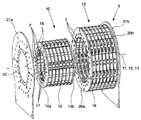
도 1a는 3개의 자화 세그먼트들을 갖는 자화 장치의 하나의 예시적인 실시예를 나타낸 도면.
도 1b는 도 la로부터의 자화 장치를 평면도를 나타낸 도면.
도 2a는 도 1a로부터의 자화 장치의 자화 세그먼트들 중 하나를 나타낸 도면.
도 2b는 도 2a의 자화 세그먼트를 분해도를 나타낸 도면.
도 3은 도 2b로부터 자화 세그먼트의 내측 자석 캐리어 및 외측 자석 캐리어를 나타낸 도면.
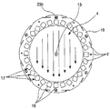
도 4a는 도 3으로부터의 내측 자석 캐리어의 내부에서의 자기장을 나타낸 도면.
도 4b는 도 3으로부터의 외측 자석 캐리어 내부에서의 자기장을 나타낸 도면.
도 5a는 내측 캐리어와 외측 캐리어 사이의 제 1 배향에서 도 2a로부터의 자화 세그먼트의 내측 캐리어의 내부를 초래하는 자기장을 나타낸 도면.
도 5b는 내측 캐리어와 외측 캐리어 사이의 제 2 배향에서 도 2a로부터의 자화 세그먼트의 내측 캐리어의 내부를 초래하는 자기장을 나타낸 도면.1A shows one exemplary embodiment of a magnetization device having three magnetization segments.
1b shows a plan view of the magnetization device from FIG.
FIG. 2A shows one of the magnetization segments of the magnetization device from FIG. 1A; FIG.
FIG. 2B is an exploded view of the magnetization segment of FIG. 2A; FIG.
FIG. 3 shows the inner magnet carrier and outer magnet carrier of the magnetization segment from FIG. 2B;
4A shows a magnetic field inside the inner magnet carrier from FIG. 3.
4b shows a magnetic field inside the outer magnet carrier from FIG.
5A shows a magnetic field resulting in the interior of the inner carrier of the magnetization segment from FIG. 2A in a first orientation between the inner and outer carriers.
FIG. 5B shows a magnetic field resulting in the interior of the inner carrier of the magnetization segment from FIG. 2A in a second orientation between the inner and outer carriers.
본 발명에 청구된 것과 같이, 그것은 측정 튜브(5)의 종축을 따라 자화 거리(7)에 걸쳐 측정 튜브(5)를 통해 흐르는 매체(6)의 자화를 위한 자화 장치(1)를 갖는, 측정 튜브(5)를 통해 흐르는 매체(6)를 측정하기 위한 핵자기 유량계이다. 여기서 매체(6)를 자화하기 위해 사용되는 자기장(3, 4)을 생성하기 위한 자화 장치(1)에는 영구 자석들(2)이 제공되고 자화 장치(1)는 측정 튜브(5)의 종축(8)의 방향에서 연속하여 위치된 적어도 2개의 자화 세그먼트들(9)을 가진다. 이것은 도면들에 크게 도시되어 있지 않은 데, 그 이유는 도면들은 본 발명에 청구된 것과 같은 핵자기 유량계에 속하는 자화 장치(1)를 기본적으로 나타내기 때문이다.As claimed in the invention, it has a magnetizing
본 발명에 청구된 것과 같이, 매체(6) 내의 자기장(3, 4)은 전체 자화 거리(7)에 걸쳐 동일한 방향을 가진다.As claimed in the present invention, the
도면들은 본 발명에 청구된 것과 같은 핵자기 유량계에 속하는 자화 장치(1)의 하나의 예시적인 실시예를 나타내고, 도 la는 그 전체가 자화 장치(1)를 나타낸다.The figures show one exemplary embodiment of a magnetizing
복수의 바 형상 영구 자석들(2) - 도 2a 내지 도 5b 참조 - 은 측정 튜브(5)를 통해 흐르는 매체(6)를 침투하는 자기장(3, 4)을 발생시킨다 - 도 1b 및 도 3 내지 도 5b 참조 -. 지구 자기장은 무시된다. 자기장(3, 4)에 의한 매체(6)의 침투(permeation)는 측정 튜브(5)의 종축(8)을 따라 연장하는 자화 거리(7)에 걸쳐 일어난다. 물론 측정 튜브(5)는, 적어도 자화 거리(7)에 걸쳐, 자기장들에 영향을 주지 않는 재료를 갖는다. 유동 매체(6)의 자화는 자화 거리(7)의 영역에서 매체(6)의 체류 시간 동안 일어나고, 체류 시간은 자화 거리(7)의 길이 및 매체(6)의 유속을 추종한다.The plurality of bar-shaped permanent magnets 2-see FIGS. 2A-5B-generate
자화 장치(1)는 개개의 자화 세그먼트들(9)로 구성되는 모듈식(modular)이고, 즉, 그것은 임의의 수의 자화 세그먼트들(9)을 포함할 수 있다. 예시적인 실시예는 3개의 자화 세그먼트들(9)을 포함하지만 - 도 la 참조 -, 모듈성(modularity)으로 인해, 또한 몇개 이상의 자화 세그먼트들(9)을 가질 수 있다.The
도시된 예시적인 실시예에 있어서, 3개의 자화 세그먼트들(9)은 각각 자화 거리(7)를 함께 형성하는 동일한 길이의 부분 자화 거리들을 형성한다. 자화 거리(7)에 걸쳐 매체(6)에서 영구 자석들(2)에 의해 발생된 자기장(3, 4)은 단지 단일 방향을 가진다 - 도 1b 참조. 만약 여기서 자화 거리(7)에 걸쳐 매체(6) 내의 자기장(3, 4)의 단일 방향이 다루어지면, 이것은 방향의 변동들(fluctuations)을 불가능하게 한다. 그러나, 방향의 변동들이 너무 작아 원하는 측정 정밀도가 달성된다. 자기장(3, 4)의 에지 효과들은, 예를 들어 자화 거리(7)의 단부들 상에서 발생하기 때문에, 도면들에 도시되지 않는다.In the exemplary embodiment shown, the three
도 2a 및 도 2b는 3개의 자화 세그먼트들(9)의 각각의 중요한 구성요소들을 나타내고, 도 2a는 조립된 상태로 자화 세그먼트(9)를 나타내고 도 2b는 자화 세그먼트(9)를 분해도로 나타낸다. 자화 세그먼트(9)는 그것의 동심 종축(11)을 갖는 기본적으로 중공 실린더 내측 캐리어(10) 및 그것의 동심 종축(13)을 갖는 기본적으로 중공 실린더 외측 캐리어(12)를 포함하고, 외측 캐리어(12)는 세그먼트의 회전축(14) 주위에서 회전시킬 수 있다.2a and 2b show the respective important components of the three
내측 캐리어(10)는 기본적으로 중공 실린더 내측 자석 캐리어(15) 및 2개의 디스크 링형상 내측 링들(168, 16b)로 기본적으로 구성되고, 내측 캐리어의 종축(11) 주위의 내측 캐리어(10)의 내경은 측정 튜브(5)의 외경보다 크다. 내측 자석 캐리어(15)에 복수의 막대 자석 리시버들(17)이 있다. 각각의 막대 자석 리시버들(17)은 내측 캐리어의 종축(11)에 평행한 축선을 가지며, 복수의 막대 자석 리세스들(18)에 동심으로 제공되는 복수의 막대 자석 리세스들(18)로 구성된다. 막대 자석 리시버들(17)은 내측 자석 캐리어(15)의 전체 길이에 걸쳐 연장하고, 막대 자석 리시버(17)에 속하는 모든 막대 자석 리세스들(18)은 동일한 직사각형 내단면을 가진다. 본체의 길이가 다루어질 경우, 본체의 종축에 따른 본체의 연장을 의미한다. 바-형상 영구 자석들(2)은 막대 자석 리시버들(17) 내에 삽입된다. 영구 자석들(2)은 내측 자석 캐리어(15)의 일 측면으로부터 또는 다른 측면으로부터 막대 자석 리시버들(17) 내로 가압되고, 삽입된 영구 자석들(2)의 길이는 내측 자석 캐리어(15)의 길이에 대응한다. 내측 자석 캐리어(15)가 이들 각각의 종축 주위를 회전할 수 있도록 막대 자석 리시버들(17)에 삽입된 영구 자석들(2)과 정렬하도록 막대 자석 리세스들(18)의 내단면들은 영구 자석들(2)의 외단면들에 매칭된다. 내측 자석 캐리어(15)는 내측 캐리어의 종축(11)의 방향에서 삽입된 영구 자석들(2)의 이동들을 방해하지 않는 데, 그 이유는 삽입된 영구 자석들(2)이 이 방향으로 이동될 수 있기 때문이다.The
내측 링(16a)은 일측면에 단단히 연결되고, 내측 링(16b)은 나사 연결들에 의해 내측 자석 캐리어(15)의 다른 측면에 연결된다. 내측 자석 캐리어(15)에 연결되는 내측 링들(16a, 16b)은 내측 캐리어의 종축(11)의 방향에서 삽입된 영구 자석들(2)의 이동을 방해한다. 삽입된 영구 자석들(2)은 표면들이 서로 매칭되는 삽입된 영구 자석들(2) 및 막대 자석 리시버들(18)의 횡단면들 및 내측 링들(16a, 16b)에 의해 완전히 고정된다. 외측을 가리키는 내측 링들(16a, 16b) 각각의 표면은 내측 캐리어의 종축(11)에 수직인 평면에 놓인다. 외측을 향하는 내측 링(16a)의 동심 표면 및 외측을 향하는 내측 링(16b)의 동심 표면은 내측 자석 캐리어(15)에 의해 관통되지 않는 공통의 내측 원형 실린더 표면에 놓인다. 내측 자석 캐리어(15) 및 그것에 연결되는 내측 링들(16a, 16b)은 내측 캐리어의 종축(11)에 동심으로 정렬된다.The
외측 캐리어(12)는 기본적으로 중공 실린더 외측 자석 캐리어(19) 및 2개의 디스크 링형상 외측링들(20a, 20b)로 기본적으로 구성된다. 외측 자석 캐리어(19)에는 복수의 막대 자석 리시버들(17)이 있다. 각각의 막대 자석 리시버들(17)은 외측 캐리어의 종축(13)에 평행한 축선을 가지며, 복수의 막대 자석 리세스들(18) 각각의 축선에 동심으로 제공되는 복수의 막대 자석 리세스들(18)로 구성된다. 막대 자석 리시버들(17)은 외측 자석 캐리어(19)의 전체 길이에 걸쳐 연장하고, 막대 자석 리시버(17)에 속하는 모든 막대 자석 리세스들(18)은 동일한 직사각형 내단면을 가진다. 직사각형 바-형상 영구 자석들(2)은 막대 자석 리시버들(17)에 삽입된다. 영구 자석들(2)은 외측 자석 캐리어(19) 또는 다른 것의 일측면으로부터 막대 자석 리시버들(17)로 밀리고, 삽입된 영구 자석들(2)의 길이는 외측 자석 캐리어(19)의 길이에 대응한다. 외측 자석 캐리어(19)이 막대 자석 리시버들(17) 각각의 종축 주위에서 회전할 수 있도록 막대 자석 리시버들(17)에 삽입되는 영구 자석들(2)을 정렬시키도록 막대 자석 리세스들(18)의 내단면들은 영구 자석들의 외단면들에 매칭된다. 내측 자석 캐리어(15)는 외측 캐리어의 종축(13)의 방향에서 삽입된 영구 자석들(2)의 이동들을 방해하지 않는데, 그 이유는 삽입된 영구 자석들(2)이 이 방향에서 이동될 수 있기 때문이다.The
외측링(20a)은 일측면에 단단히 연결되고, 외측링(20b)은 나사 연결들에 의해 외측 자석 캐리어(19)의 다른 측면에 연결된다. 외측 자석 캐리어(19)에 연결되는 외측링들(20a, 20b)은 외측 캐리어의 종축(13)의 방향에서 삽입된 영구 자석들(2)의 이동을 방해한다. 삽입된 영구 자석들(2)은 삽입된 영구 자석들(2), 및 표면들이 서로 매치되는 막대 자석 리세스들(18)의 횡단면들 및 외측링들(20a, 20b)에 의해 완전히 고정된다. 외측을 향하는 외측링들(20a, 20b) 각각의 표면은 외측 캐리어의 종축(13)에 수직인 평면에 놓인다. 내측을 향하는 외측링(20a)의 동심 표면 및 내측을 향하는 외측링(20b)의 동심 표면은 외측 자석 캐리어(19)에 의해 관통되지 않는 공통의 외측의 원형 실린더 표면에 놓인다. 외측 자석 캐리어(19), 및 그것에 연결되는 내측 링들(20a, 20b)은 외측 캐리어의 종축(13)에 동심으로 정렬된다.The
내측 캐리어(10)의 길이는 외측 캐리어(12)의 길이보다 보다 약간 작고 외측 원형 실린더 표면의 반경은 내측의 원형 실린더 표면의 반경보다 약간 크다. 내측 캐리어(10) 및 외측 캐리어(12)는 내측 캐리어 위에서 라우팅되는 외측 캐리어(12)에 의해 연결된다. 연결된 상태에서 내측 캐리어의 종축(11) 및 외측 캐리어의 종축(13)은 일치하고, 표면들이 외측을 향하는, 내측 링들(16a, 16b)의 표면들은 외측을 향하는 외측링들(20a, 20b)의 표면들 위로 약간 돌출한다.The length of the
각각의 자화 세그먼트들(9)은 내측 캐리어(10) 및 외측 캐리어(12) 외에 2개의 평판형 세그먼트 캐리어들(21a, 21b)을 기본적으로 포함한다. 각각의 세그먼트 캐리어들(21a, 21b)에는 측정 튜브(5)를 라우팅하기 위한 원형의 튜브 리세스(22)가 있다. 세그먼트 캐리어(21a)는 내측 링(16a)에 나사 연결들에 의해 확실하게 연결되고 세그먼트 캐리어(21b)는 내측 링(16b)에 나사 연결들에 의해 확실하게 연결된다. 내측 캐리어의 종축(11)에 수직인 일평면에서 세그먼트 캐리어들(21a, 21b)의 연장부는 이 평면에서 외측 캐리어(12)의 연장부 위로 돌출한다.Each
내측 캐리어(10)를 참조하여 외측 캐리어의 종축(13)에 반경방향인 방향에서 외측 캐리어(12)의 이동들은 2개의 레이디얼 슬라이드 베어링들에 방해를 받는다. 제 1의 레이디얼 슬라이드 베어링은 외측을 향하는 내측 링(16a)의 반경방향 표면들과 함께 내측을 향하는 외측링(20a)의 반경방향 표면에 의해 형성되고, 제 2 레이디얼 슬라이드 베어링은 외측을 향하는 내측 링(16b)의 반경방향 표면들과 함께 내측을 향하는 외측링(20b)의 반경방향 표면에 의해 형성된다.Movements of the
내측 캐리어(10)에 대한 외측 캐리어의 종축(13)에 축방향인 방향에서 외측 캐리어(12)의 이동들은 2개의 액시얼 슬라이드 베어링에 의해 방해를 받는다. 제 1의 액시얼 슬라이드 베어링은 내측을 향하는 세그먼트 캐리어(21a)의 표면과 함께 외측을 향하는 외측링(20a)의 측면의 표면에 의해 형성되고, 제 2의 액시얼 슬라이드 베어링은 내측을 향하는 세그먼트 캐리어(21b)의 표면과 함께 외측을 향하는 외측링(20b)의 측면의 표면에 의해 형성된다.Movements of the
내측 캐리어(10)에 대한 외측 캐리어(12)의 단독으로 남아 있는 이동 자유도는 외측 캐리어의 종축(13) 주위에서의 회전이다. 규정에 의해 세그먼트의 종축(14)은 외측 캐리어의 종축(13)과 일치한다. 외측 원형 실린더 표면 및 내측 원형 실린더 표면의 반경들의 위에서의 언급한 약간의 차이는 래디얼 슬라이드 베어링의 기능이 보장되게 하고 내측 캐리어(10) 및 외측 캐리어(12)의 길이들의 위에서 언급한 약간의 차이는 액시얼 슬라이드 베어링의 기능이 보장되게 한다. 서로 접촉하는 래디얼 슬라이드 베어링 및 액시얼 슬라이드 베어링의 표면들은 외측 캐리어(12)가 내측 캐리어(10)에 대해 회전할 때 마모 및 회전에 필요한 토크가 가능한 한 작게 한다.The remaining freedom of movement of the
도 3은 삽입된 영구 자석들(2)과 연결된 상태의 내측 자석 캐리어(15) 및 외측 자석 캐리어(19)를 나타낸다. 내측 자석 캐리어(15)의 원통형 내부의 자기장(3, 4)은 내측 자석 캐리어(15)의 영구 자석들(2)의 자기장(3) 및 외측 자석 캐리어(19)의 영구 자석들(2)의 자기장(4)의 중첩으로부터 생긴다. 세그먼트의 회전축(14)에 평행한 어떤 선에 따른 매체(6) 내에서의 자기장(3, 4)의 자기장 강도는 자화 세그먼트(9)의 길이에 걸쳐 일정하다. 더욱이, 자기장(3, 4)은 자화 세그먼트(9)의 길이에 걸쳐 균일하다. 만약 자화 세그먼트(9)의 길이에 걸쳐 매체(6) 내에서의 자기장(3, 4)의 균질성(homogeneity) 또는 일정한 자기장 강도가 여기서 다루어지면, 이것은 자기장(3, 4)의 균질성들 및 자기장 강도의 변동들을 불가능하게 하지 않는다. 그렇지만, 자기장 강도 및 균질성들의 변동들이 너무 작아 원하는 측정 정밀도가 달성된다.3 shows the
내측 자석 캐리어(15)에 대한 외측 자석 캐리어(19)의 배향은 내측 자석 캐리어(15) 면 상에 배향 마크(23a) 및 외측 자석 캐리어(19) 면 상에 배향 마크(23b)에 의해 특징지워진다. 측정 튜브(5)의 내측 자석 캐리어(15)의 반경방향 거리 및 내측 자석 캐리어(15)로부터의 외측 자석 캐리어(19)의 반경방향 거리는 가능한 한 작아야 한다. 짧은 거리들로 인해, 자기장(3, 4)이 침투되고 측정 튜브(5)가 위치되는 볼륨은 최소로 되고 따라서 따라서 영구 자석들(2)에 의해 가해지는 자속 또한 최소로 된다. 따라서, 반경방향 거리들이 크면 클수록 영구 자석 재료가 더 많이 필요하다.The orientation of the
도 4a는 삽입된 영구 자석들(2)을 갖는 내측 자석 캐리어(15)를 평면도로 나타낸다. 내측 자석 캐리어(15)는 자기장(3)이 기본적으로 내측 자석 캐리어(15)의 원통형 내부로 내측 자석 캐리어(15) 외부로 연장하고, 매체(6)에서 균일한 삽입된 영구 자석들(2)을 할바흐 배열(Halbach array)로 정렬한다. 도 4b는 삽입된 영구 자석들(2)을 갖는 외측 자석 캐리어(19)를 평면도로 나타낸다. 외측 자석 캐리어(19)는 삽입된 영구 자석들(2)을 마찬가지로 자기장(3)이 기본적으로 내측 자석 캐리어(15)의 원통형 내부로 내측 자석 캐리어(15) 외부로 연장하고, 매체(6)에서 균일한 삽입된 영구 자석들(2)을 할바흐 배열로 정렬한다. 매체(6)에서의 자기장(3) 및 자기장(4)의 강도들의 양들이 동일하도록 2개의 할바흐 배열들은 서로 매칭된다. 자기장(3)이 내측 캐리어(15)의 외부로 연장하지 않는 환경으로 인해, 단지 래디얼 슬라이드 베어링 및 액시얼 슬라이드 베어링의 마찰만이 외측 캐리어(12)를 회전시키기 위해 극복될 필요가 았다.4a shows, in plan view, an
도 5a는 서로에 대해 제 1 배향으로 삽입된 영구 자석들(2)을 갖는 내측 자석 캐리어(15) 및 외측 자석 캐리어(19)를 나타낸다. 자기장(3) 및 자기장(4)은 서로 평행하게 정렬된다. 따라서, 매체(6)에서, 중첩에 의해 생기는 자기장의 자기장 강도는 단독으로 고려되는 자기장(4) 또는 자기장(3)의 자기장 강도의 2배이다. 도 5b는 서로에 대해 제 2 배향으로 삽입된 영구 자석들(2)을 갖는 내측 자석 캐리어(15) 및 외측 자석 캐리어(19)를 나타낸다. 자기장(3) 및 자기장(4)은 서로 평행하지 않게 정렬된다. 그러므로, 매체(6) 내에는 자기장이 없다. 만약 매체(6) 내의 자기장의 존재가 다루어지면, 이것은 작은 자기장 강도를 갖는 매체(6) 내에 존재하는 자기장을 배제하지 않는다. 그렇지만, 나머지 자기장 강도는 너무 작아서 원하는 측정 정밀도가 달성된다.5a shows an
자화 장치(1)의 3개의 자화 세그먼트들(9)은 - 도 1a 참조 - 이들 세그먼트들의 회전축(14)이 측정 튜브(5)의 종축(8)과 일치하도록 서로 정렬된다. 또한, 내측 캐리어들(10)은 이들 자기장들(3)이 평행하도록 서로 배향된다. 각각의 외측 캐리어들(12)은 다른 외측 캐리어들(12)과 무관하게 측정 튜브(5)의 종축(8) 주위로 회전될 수 있고, 각각의 외측 캐리어들(12)의 회전은 도면에는 도시되지 않은 액튜에이터에 의해 일어난다. 액튜에이터들은 내측 캐리어들(10)에 대해 외측 캐리어들(12)의 임의의 배향을 설정할 수 있다.The three
자화 장치(1)를 동작시키기 위한 러스트 방법(rust method)에 있어서, 3개의 외측 캐리어들(12)은 자기장들(4)이 서로 평행하도록 항상 액튜에이터들에 의해 서로에 대해 배향된다. 따라서, 3개의 외측 캐리어들(12)의 회전들이 함께 그리고 균일하게 내측 캐리어들(10)에 대해 일어난다. 내측 캐리어들(10)에 대한 외측 캐리어들(12)의 회전들에 의해, 매체(6) 내의 자기장(3, 4)은 단독으로 관측된 자기장(3) 또는 자기장(4)의 자기장 강도의 2배 사이의 임의의 자기장 강도들까지 자화 거리(7)에 걸쳐 설정된다. 그 결과, 유동 매체(6)의 자화가 그에 따라 변한다. 자화 거리(7)에 걸친 매체(6) 내의 자기장(3, 4)은 단지 단일 방향을 가진다. 게다가, 매체(6) 내에서의 자기장(3, 4)의 자기장 강도는 자화 거리(7)에 걸쳐 측정 튜브의 종축(8)에 평행한 임의의 선을 따라 일정하다. 더욱이, 자기장(3, 4)은 자화 거리(7)에 걸쳐 균일하다.In the rust method for operating the
자화 장치(1)를 동작시키기 위한 제 2 방법에 있어서, 3개의 자화 세그먼트들(9)의 외측 캐리어들(12)은 서로에 대해 독립적으로 배향된다. 여기서 각각의 외측 캐리어들(12)의 단지 2개의 상이한 배향들이 그것의 내측 캐리어(10)에 대해 설정된다. 제 1 배향에서 각각의 자화 세그먼트(9)의 자기장(3) 및 자기장(4)은 평행하게 정렬된다. 매체(6) 내에서의 자기장(3, 4)의 자기장 강도는 단독으로 관측된 자기장(4) 또는 자기장(3)의 자기장 강도의 2배이다. 제 2 배향에서 자기장(3) 및 자기장(4)은 평행하지 않게 정렬된다. 매체(6) 내에서의 자기장 강도(3, 4)는 영이다. 이러한 방법으로 생성될 수 있는 매체(6)의 자화들을 위해, 자화는 항상 매체(6) 내에서 동일한 자기장 강도로 발생한다. 매체(6) 내에서의 자기장(3, 4)은 자화 거리(7)에 걸쳐 개개의 자화 세그먼트들(9)의 외측 캐리어(12)의 배향들과 무관하게, 단지 단일 방향을 가진다.In a second method for operating the
1: 자화 장치 2: 영구 자석
3, 4: 자기장 5: 측정 튜브
6: 매체 7: 자화 거리
8: 측정 튜브의 종축 9: 자화 세그먼트
10: 내측 캐리어 11: 내측 캐리어의 종축
12: 외측 캐리어 13: 외측 캐리어의 종축
14. 세그먼트의 회전 축선 15: 내측 자석 캐리어
16a, 16b: 내측 링 17: 막대 자석 리시버들
18: 막대 자석 리세스 19: 외측 자석 캐리어
20a, 20b: 외측링 21a, 2lb: 세그먼트 캐리어
22: 튜브 리세스 23a, 23b: 캐리어 배향 마크1: magnetization device 2: permanent magnet
3, 4: magnetic field 5: measuring tube
6: medium 7: magnetization distance
8: longitudinal axis of measuring tube 9: magnetization segment
10: inner carrier 11: longitudinal axis of the inner carrier
12: outer carrier 13: longitudinal axis of the outer carrier
14. Rotation axis of the segment 15: Inner magnet carrier
16a, 16b: inner ring 17: bar magnet receivers
18: bar magnet recess 19: outer magnet carrier
20a, 20b:
22:
Claims (16)
상기 자기장(3, 4)은 동일한 방향을 가지며, 또는 모든 자기장들(3, 4)은 상기 전체 자화 거리(7)에 걸쳐 상기 매체(6) 내에서의 상기 자화 거리(7)의 길이에 걸쳐 상이한 자기장 강도에서 동일한 방향을 가지는 것을 특징으로 하는, 핵자기 유량계.A nuclear magnetic flowmeter for measuring the flow rate of the medium 6 flowing through the measurement tube 5, the nuclear magnetic flowmeter measuring the measurement over the magnetization distance 7 along the longitudinal axis 8 of the measurement tube 5. Said magnetizing device (1) having a magnetizing device (1) for magnetizing said medium (6) flowing through a tube (5) and for generating said magnetic fields (3, 4) used to magnetize said medium (6) Is a nuclear magnetic flowmeter in which permanent magnets (2) are installed and have at least two magnetization segments (9) positioned continuously in the direction of the longitudinal axis (8) of the measuring tube (5),
The magnetic fields 3, 4 have the same direction, or all the magnetic fields 3, 4 over the entire magnetization distance 7 over the length of the magnetization distance 7 in the medium 6. A nuclear magnetic flow meter, characterized in that it has the same direction at different magnetic field intensities.
각각의 상기 자화 세그먼트들(9)은 영구 자석들(2)이 장비된 내측 캐리어(10) 및 영구 자석들(2)이 장비된 외측 캐리어(12)를 가지며, 상기 내측 캐리어(10)는 상기 측정 튜브(5) 주위에 배치되고, 상기 외측 캐리어(12)는 상기 내측 캐리어(10) 주위에 배치되고, 상기 내측 캐리어(10)와 상기 외측 캐리어(12) 사이의 배향은 상기 매체(6) 내에서의 상기 자기장 강도의 변동 및 따라서 또한 상기 매체(6)의 상기 자화의 변동을 위해 세그먼트의 회전축(14) 주위에서의 상기 내측 캐리어(10) 및/또는 상기 외측 캐리어(12)의 회전에 의해 조정될 수 있는, 핵자기 유량계.The method of claim 1,
Each of the magnetization segments 9 has an inner carrier 10 equipped with permanent magnets 2 and an outer carrier 12 equipped with permanent magnets 2, the inner carrier 10 being the Disposed around the measurement tube 5, the outer carrier 12 is disposed around the inner carrier 10, and the orientation between the inner carrier 10 and the outer carrier 12 is determined by the medium 6. Rotation of the inner carrier 10 and / or the outer carrier 12 around the axis of rotation 14 of the segment for variation of the magnetic field strength within the device and thus also of the magnetization of the medium 6. Nuclear magnetic flow meter, which can be adjusted by.
각각의 상기 자화 요소들(9)에 대해, 상기 내측 캐리어(10)와 상기 외측 캐리어(12) 사이의 상기 배향은 상기 매체(6) 내에서 상기 최대 필드 강도(3, 4)로 설정되고, 또는 상기 내측 캐리어(10)와 상기 외측 캐리어(12) 사이의 상기 배향은 상기 매체(6) 내에서 상기 최소 필드 강도(3, 4)로 설정되는, 핵자기 유량계.3. The method of claim 2,
For each of the magnetizing elements 9, the orientation between the inner carrier 10 and the outer carrier 12 is set to the maximum field strengths 3, 4 in the medium 6, Or the orientation between the inner carrier (10) and the outer carrier (12) is set to the minimum field strength (3, 4) in the medium (6).
상기 자화 세그먼트들(9) 중 적어도 하나에 있어서, 상기 내측 캐리어(10)의 상기 자기장(3) 및 상기 외측 캐리어(12)의 상기 자기장(4)은 상기 매체(6) 내에서 상기 최소 자기장 강도(3, 4)를 위한 상기 내측 캐리어(10)와 상기 외측 캐리어(12) 사이의 상기 배향에서, 상기 매체(6) 내에 자기장이 없도록 형성되는, 핵자기 유량계.4. The method according to any one of claims 1 to 3,
In at least one of the magnetization segments 9, the magnetic field 3 of the inner carrier 10 and the magnetic field 4 of the outer carrier 12 are the minimum magnetic field strength in the medium 6. A nuclear magnetic flow meter, formed so that there is no magnetic field in the medium (6) in the orientation between the inner carrier (10) and the outer carrier (12) for (3, 4).
상기 자화 세그먼트들(9) 중 적어도 하나에 있어서, 상기 내측 캐리어(10)는 상기 측정 튜브(5)에 관해 정지하고 상기 외측 캐리어(12)는 상기 세그먼트의 회전축(14) 주위에서 회전할 수 있도록 장착되는, 핵자기 유량계.5. The method according to any one of claims 2 to 4,
In at least one of the magnetization segments 9, the inner carrier 10 stops with respect to the measuring tube 5 and the outer carrier 12 is able to rotate about the axis of rotation 14 of the segment. Equipped, nuclear magnetic flowmeter.
상기 자화 세그먼트들(9) 중 적어도 하나에 있어서, 세그먼트의 상기 회전축(14)에 대해 각각의 자화 세그먼트의 2개의 단부들 상의 상기 내측 캐리어(10)는 한번에 하나의 세그먼트 캐리어(21a, 21b)에 확실하게 연결되고, 상기 내측 캐리어(10)를 갖는 상기 외측 캐리어(12)는 적어도 하나의 래디얼 슬라이드 베어링을 형성하고 상기 세그먼트 캐리어들(21a, 21b)을 갖는 상기 외측 캐리어(12)는 적어도 하나의 액시얼 슬라이드 베어링을 형성하는, 핵자기 유량계.6. The method according to any one of claims 2 to 5,
In at least one of the magnetization segments 9, the inner carrier 10 on the two ends of each magnetization segment with respect to the axis of rotation 14 of the segment is connected to one segment carrier 21a, 21b at a time. Securely connected, the outer carrier 12 with the inner carrier 10 forms at least one radial slide bearing and the outer carrier 12 with the segment carriers 21a, 21b is at least one. A nuclear magnetic flow meter, forming an axial slide bearing.
상기 자화 세그먼트들 중 적어도 하나에는, 상기 세그먼트의 상기 회전축(14) 주위에서의 상기 내측 캐리어(10) 및/또는 상기 외측 캐리어(12)의, 바람직하게는 상기 외측 캐리어(12)의 회전을 위한 액튜에이터가 있는, 핵자기 유량계.The method according to any one of claims 2 to 6,
At least one of the magnetization segments is adapted for rotation of the inner carrier 10 and / or the outer carrier 12, preferably for the outer carrier 12, around the axis of rotation 14 of the segment. Nuclear magnetic flowmeter with actuator.
상기 자화 세그먼트들(9) 중 적어도 하나에 있어서, 적어도, 상기 매체(6) 내에서 상기 최소 자기장(3, 4)을 갖는, 상기 내측 캐리어(10)와 상기 외측 캐리어(12) 사이의 상기 배향 및 상기 매체(6) 내에서 상기 최대 자기장(3, 4)을 갖는, 상기 내측 캐리어(10)와 상기 외측 캐리어(12) 사이의 상기 배향은 상기 액튜에이터에 의해 조정될 수 있는, 핵자기 유량계.The method of claim 7, wherein
In at least one of the magnetization segments 9, at least the orientation between the inner carrier 10 and the outer carrier 12, having the minimum magnetic fields 3, 4 in the medium 6. And said orientation between said inner carrier (10) and said outer carrier (12) having said maximum magnetic field (3, 4) in said medium (6) can be adjusted by said actuator.
영구 자석들(2)이 장비되는 적어도 추가의 하나의 자화 세그먼트(9)가 있고, 상기 추가의 자화 세그먼트(9)의 자기 저항은 상기 매체(6)에서의 상기 자기장 강도(3, 4)의 변동 및 따라서 또한 상기 매체(6)의 상기 자화의 변동을 위해 조정될 수 있는, 핵자기 유량계.The method according to any one of claims 1 to 8,
There is at least one further magnetization segment 9 equipped with permanent magnets 2, the magnetic resistance of the further magnetization segment 9 being of the magnetic field strength 3, 4 in the medium 6. A nuclear magnetic flowmeter, which can be adjusted for fluctuations and thus also for fluctuations in the magnetization of the medium (6).
상기 추가의 자화 세그먼트는 제 1 부분 세그먼트 및 제 2 부분 세그먼트로 구성되고 상기 2개의 부분 세그먼트들은 이격되어 있고, 상기 간격에 의해 상기 제 1 부분 세그먼트와 상기 제 2 부분 세그먼트 사이에서 생기는 갭은 조정 가능한 자기 저항을 구성하는, 핵자기 유량계.10. The method of claim 9,
The further magnetization segment consists of a first partial segment and a second partial segment and the two partial segments are spaced apart, and the gap created by the gap between the first partial segment and the second partial segment is adjustable. A nuclear magnetic flow meter, which constitutes a magnetoresistance.
상기 영구 자석들(2)은 할바흐 배열(Halbach array)로서 배열되는, 핵자기 유량계.11. The method according to any one of claims 1 to 10,
The permanent magnets (2) are arranged as a Halbach array.
상기 매체(6)에서 상기 자기장 강도를 변화시키고 따라서 또한 상기 매체(6)의 상기 자화를 변화시키기 위해, 상기 자화 장치(1) 상에는 적어도 하나의 전자석이 있고, 상기 전자석의 상기 자기장은 상기 자화 장치(1) 디바이스의 상기 자기장(3, 4)에 평행하거나 평행하지 않게 정렬되고, 상기 전자석에 의해 발생된 상기 자기장의 상기 강도는 조정될 수 있는, 핵자기 유량계.12. The method according to any one of claims 1 to 11,
In order to change the magnetic field strength in the medium 6 and thus also the magnetization of the medium 6, there is at least one electromagnet on the magnetization device 1, the magnetic field of the electromagnet being the magnetization device. (1) A nuclear magnetic flowmeter, aligned parallel or nonparallel to the magnetic field (3, 4) of the device, wherein the strength of the magnetic field generated by the electromagnet can be adjusted.
상기 자화 장치(1) 또는 적어도 하나 자화 세그먼트(9)는 상기 측정 튜브(5)의 상기 종축(8)을 따라 이동할 수 있도록 배열되고, 상기 매체(6)의 상기 자화는 측정 장치까지의 상기 측정 튜브(5)의 상기 종축(8)을 따라 상기 자화 장치(1) 또는 상기 자화 세그먼트(9)의 상기 조정 가능한 거리에 의해 상기 측정 장치 상에서 조정될 수 있는, 핵자기 유량계.13. The method according to any one of claims 1 to 12,
The magnetization device 1 or at least one magnetization segment 9 is arranged to be movable along the longitudinal axis 8 of the measurement tube 5, the magnetization of the medium 6 being the measurement up to the measurement device. A nuclear magnetic flowmeter, which can be adjusted on the measuring device by the adjustable distance of the magnetization device (1) or the magnetization segment (9) along the longitudinal axis (8) of the tube (5).
상기 자화 세그먼트들(9)은 상이한 길이의 부분 자화 거리들을 가지는, 핵자기 유량계.The method according to any one of claims 1 to 13,
The magnetization segments (9) have partial magnetization distances of different lengths.
상기 측정 튜브(5)의 상기 종축(8)에 평행한 임의의 선을 따라 상기 매체(6)에서 상기 영구 자석들(2)에 의해 발생된 상기 자기장의 상기 강도(3, 4)는 각각의 상기 자화 세그먼트들(9)의 상기 길이 또는 상기 자화 거리(7)에 걸쳐 일정한, 핵자기 유량계.15. The method according to any one of claims 1 to 14,
The strengths (3, 4) of the magnetic field generated by the permanent magnets (2) in the medium (6) along any line parallel to the longitudinal axis (8) of the measuring tube (5) are each A nuclear magnetic flow meter constant over the length of the magnetization segments (9) or the magnetization distance (7).
상기 매체(6) 내에서 상기 영구 자석들(2)에 의해 발생된 상기 자기장(3, 4)은 각각의 상기 자화 세그먼트들(9)의 상기 길이 또는 상기 자화 거리(7)에 걸쳐 균일한, 핵자기 유량계.16. The method according to any one of claims 1 to 15,
The magnetic fields 3, 4 generated by the permanent magnets 2 in the medium 6 are uniform over the length or magnetization distance 7 of the respective magnetization segments 9, Nuclear magnetic flowmeter.
Applications Claiming Priority (2)
| Application Number | Priority Date | Filing Date | Title |
|---|---|---|---|
| DE102012013935.7 | 2012-07-16 | ||
| DE102012013935.7A DE102012013935A1 (en) | 2012-07-16 | 2012-07-16 | Magnetization device and method for operating a magnetization device |
Publications (2)
| Publication Number | Publication Date |
|---|---|
| KR20140010341A true KR20140010341A (en) | 2014-01-24 |
| KR102031217B1 KR102031217B1 (en) | 2019-10-11 |
Family
ID=48782126
Family Applications (1)
| Application Number | Title | Priority Date | Filing Date |
|---|---|---|---|
| KR1020130082828A KR102031217B1 (en) | 2012-07-16 | 2013-07-15 | Nuclear magnetic flowmeter |
Country Status (14)
| Country | Link |
|---|---|
| US (1) | US9429456B2 (en) |
| EP (1) | EP2687825B1 (en) |
| JP (1) | JP6198497B2 (en) |
| KR (1) | KR102031217B1 (en) |
| CN (1) | CN103542899B (en) |
| AR (1) | AR091761A1 (en) |
| AU (1) | AU2013206720B2 (en) |
| BR (1) | BR102013018079A2 (en) |
| CA (1) | CA2820828C (en) |
| DE (1) | DE102012013935A1 (en) |
| MX (1) | MX2013008206A (en) |
| MY (1) | MY172631A (en) |
| RU (1) | RU2606546C2 (en) |
| SA (1) | SA113340718B1 (en) |
Families Citing this family (18)
| Publication number | Priority date | Publication date | Assignee | Title |
|---|---|---|---|---|
| US9395222B2 (en) * | 2011-11-20 | 2016-07-19 | Krohne Ag | Magnetization device for a nuclear magnetic flow meter |
| EP3011369B1 (en) | 2013-06-20 | 2019-12-11 | Aspect International (2015) Private Limited | An nmr/mri-based integrated system for analyzing and treating of a drilling mud for drilling mud recycling process and methods thereof |
| US9494503B2 (en) | 2013-11-06 | 2016-11-15 | Aspect Imaging Ltd. | Inline rheology/viscosity, density, and flow rate measurement |
| DE102015001161A1 (en) * | 2014-08-29 | 2016-03-03 | Krohne Ag | A method of operating a nuclear magnetic flowmeter and nuclear magnetic flowmeter |
| DE102015005300A1 (en) * | 2014-11-27 | 2016-06-02 | Krohne Ag | Method of operating a nuclear magnetic flowmeter |
| EP3245486B1 (en) * | 2015-01-16 | 2020-10-14 | Sanofi-Aventis Deutschland GmbH | Drug delivery device with flow rate sensor |
| WO2016116926A1 (en) | 2015-01-19 | 2016-07-28 | Aspect International (2015) Private Limited | Nmr-based systems for crude oil enhancement and methods thereof |
| CN106053299B (en) | 2015-04-12 | 2020-10-30 | 艾斯拜克特Ai有限公司 | NMR imaging of fluids in non-circular cross-section conduits |
| CN106324010A (en) | 2015-07-02 | 2017-01-11 | 艾斯拜克特Ai有限公司 | Analysis of fluids flowing in a conduit using MR equipment |
| US10655996B2 (en) | 2016-04-12 | 2020-05-19 | Aspect Imaging Ltd. | System and method for measuring velocity profiles |
| DE102016109993A1 (en) * | 2016-05-31 | 2017-11-30 | Krohne Ag | A method of operating a nuclear magnetic flowmeter and nuclear magnetic flowmeter |
| AU2017409020B2 (en) * | 2017-04-13 | 2024-03-07 | The University Of Queensland | Measurement magnet arrangement |
| US11460330B2 (en) | 2020-07-06 | 2022-10-04 | Saudi Arabian Oil Company | Reducing noise in a vortex flow meter |
| CN111759306B (en) * | 2020-08-04 | 2023-11-24 | 重庆邮电大学 | Unilateral magnetic particle imaging detection device |
| US11525723B2 (en) | 2020-08-31 | 2022-12-13 | Saudi Arabian Oil Company | Determining fluid properties |
| US11428557B2 (en) | 2020-08-31 | 2022-08-30 | Saudi Arabian Oil Company | Determining fluid properties |
| US11549836B2 (en) | 2021-05-26 | 2023-01-10 | Saudi Arabian Oil Company | Liquid NMR signal boost during NMR flow metering of wet gas flow using enhanced signal relaxation and/or dynamic nuclear polarisation using immobilised radicals |
| RU207846U1 (en) * | 2021-09-06 | 2021-11-19 | ООО "Мехатрон сервис" | ELECTROMAGNETIC FLOW METER |
Citations (3)
| Publication number | Priority date | Publication date | Assignee | Title |
|---|---|---|---|---|
| US4862128A (en) * | 1989-04-27 | 1989-08-29 | The United States Of America As Represented By The Secretary Of The Army | Field adjustable transverse flux sources |
| US20020140425A1 (en) * | 2001-03-28 | 2002-10-03 | Prammer Manfred G. | Magnetic resonance fluid analysis apparatus and method |
| US20080174309A1 (en) * | 2006-11-29 | 2008-07-24 | Spinlock Srl | Magnetic resonance based apparatus and method to analyze and to measure the bi-directional flow regime in a transport or a production conduit of complex fluids, in real time and real flow-rate |
Family Cites Families (14)
| Publication number | Priority date | Publication date | Assignee | Title |
|---|---|---|---|---|
| US4782295A (en) * | 1987-06-01 | 1988-11-01 | Lew Hyok S | Nuclear magnetic resonance flowmeter |
| GB2291198B (en) * | 1994-07-06 | 1999-01-13 | Alwin Bayer | Detection of magnetised fluid flows |
| RU2152006C1 (en) * | 1998-03-12 | 2000-06-27 | ТОО "Фирма "Юстас" | Nuclear-magnetic flow meter for multiphase medium |
| US6535092B1 (en) * | 1999-09-21 | 2003-03-18 | Magnetic Solutions (Holdings) Limited | Device for generating a variable magnetic field |
| US6320488B1 (en) * | 2000-07-31 | 2001-11-20 | The United States Of America As Represented By The Secretary Of The Army | Magic cylinder adjustable in field strength |
| US6577125B2 (en) * | 2000-12-18 | 2003-06-10 | Halliburton Energy Services, Inc. | Temperature compensated magnetic field apparatus for NMR measurements |
| US8248067B2 (en) * | 2004-09-24 | 2012-08-21 | Baker Hughes Incorporated | Apparatus and methods for estimating downhole fluid compositions |
| GB0421266D0 (en) * | 2004-09-24 | 2004-10-27 | Quantx Wellbore Instrumentatio | Measurement apparatus and method |
| US6989730B1 (en) * | 2005-05-24 | 2006-01-24 | The United States Of America As Represented By The Secretary Of The Army | Adjustable toroidal magnet |
| DE102006031425A1 (en) * | 2006-07-05 | 2008-01-10 | Forschungszentrum Jülich GmbH | Magnetic system with variable field strength |
| DE102006032896A1 (en) * | 2006-07-15 | 2008-01-17 | Fachhochschule Kiel | Device for volumetric flow rate measurement of electrically conductive liquid medium according to magnetic-inductive principle, has measuring tube through which medium flows and magnet, whose magnetic field intersperses measuring tube |
| KR20100099054A (en) * | 2009-03-02 | 2010-09-10 | 신에쓰 가가꾸 고교 가부시끼가이샤 | Permanent magnet type magnetic field generating apparatus |
| DE102014010324B3 (en) * | 2014-05-23 | 2015-02-05 | Krohne Ag | Nuclear magnetic flowmeter and method of operating a nuclear magnetic flowmeter |
| DE102014015943B3 (en) * | 2014-07-10 | 2015-07-09 | Krohne Ag | Method of operating a nuclear magnetic flowmeter |
-
2012
- 2012-07-16 DE DE102012013935.7A patent/DE102012013935A1/en not_active Ceased
-
2013
- 2013-07-03 EP EP13003370.7A patent/EP2687825B1/en active Active
- 2013-07-05 AU AU2013206720A patent/AU2013206720B2/en not_active Ceased
- 2013-07-11 MY MYPI2013701215A patent/MY172631A/en unknown
- 2013-07-11 CA CA2820828A patent/CA2820828C/en not_active Expired - Fee Related
- 2013-07-15 MX MX2013008206A patent/MX2013008206A/en active IP Right Grant
- 2013-07-15 KR KR1020130082828A patent/KR102031217B1/en active IP Right Grant
- 2013-07-15 RU RU2013132613A patent/RU2606546C2/en active
- 2013-07-15 AR ARP130102504 patent/AR091761A1/en active IP Right Grant
- 2013-07-15 SA SA113340718A patent/SA113340718B1/en unknown
- 2013-07-15 BR BRBR102013018079-3A patent/BR102013018079A2/en not_active IP Right Cessation
- 2013-07-16 US US13/943,108 patent/US9429456B2/en active Active
- 2013-07-16 JP JP2013147874A patent/JP6198497B2/en not_active Expired - Fee Related
- 2013-07-16 CN CN201310297215.XA patent/CN103542899B/en not_active Expired - Fee Related
Patent Citations (3)
| Publication number | Priority date | Publication date | Assignee | Title |
|---|---|---|---|---|
| US4862128A (en) * | 1989-04-27 | 1989-08-29 | The United States Of America As Represented By The Secretary Of The Army | Field adjustable transverse flux sources |
| US20020140425A1 (en) * | 2001-03-28 | 2002-10-03 | Prammer Manfred G. | Magnetic resonance fluid analysis apparatus and method |
| US20080174309A1 (en) * | 2006-11-29 | 2008-07-24 | Spinlock Srl | Magnetic resonance based apparatus and method to analyze and to measure the bi-directional flow regime in a transport or a production conduit of complex fluids, in real time and real flow-rate |
Also Published As
| Publication number | Publication date |
|---|---|
| RU2013132613A (en) | 2015-01-20 |
| AU2013206720A1 (en) | 2014-01-30 |
| EP2687825A2 (en) | 2014-01-22 |
| CN103542899B (en) | 2018-03-13 |
| MY172631A (en) | 2019-12-06 |
| CN103542899A (en) | 2014-01-29 |
| RU2606546C2 (en) | 2017-01-10 |
| DE102012013935A1 (en) | 2014-01-16 |
| EP2687825A3 (en) | 2015-06-24 |
| SA113340718B1 (en) | 2016-08-17 |
| CA2820828C (en) | 2018-12-11 |
| BR102013018079A2 (en) | 2015-06-30 |
| CA2820828A1 (en) | 2014-01-16 |
| EP2687825B1 (en) | 2020-08-26 |
| US9429456B2 (en) | 2016-08-30 |
| KR102031217B1 (en) | 2019-10-11 |
| JP6198497B2 (en) | 2017-09-20 |
| MX2013008206A (en) | 2014-01-21 |
| JP2014021118A (en) | 2014-02-03 |
| AR091761A1 (en) | 2015-02-25 |
| US20140028310A1 (en) | 2014-01-30 |
| AU2013206720B2 (en) | 2019-03-14 |
Similar Documents
| Publication | Publication Date | Title |
|---|---|---|
| KR102031217B1 (en) | Nuclear magnetic flowmeter | |
| AU2015200452B2 (en) | Nuclear magnetic flowmeter and method for operating a nuclear magnetic flowmeter | |
| RU2580838C2 (en) | Magnetiser for nuclear-magnetic flow meter | |
| US10151817B2 (en) | Flowmeter with a measuring device implementing a tomographic measuring principle | |
| RU2653588C2 (en) | Nuclear magnetic flowmeter and method for operating nuclear magnetic flowmeters | |
| KR20140010339A (en) | Nuclear magnetic flowmeter | |
| CA2795702C (en) | Magnet module for a nuclear magnetic flow meter | |
| CN103998945B (en) | Digital linear actuator rotor flux density scan Method and kit for | |
| CN208721168U (en) | Electromagnetic flowmeter | |
| US20230221385A1 (en) | Apparatus and method for measuring thickness of tubings in downhole applications | |
| KR100738321B1 (en) | Apparatus for measuring the magnetic moment | |
| WO2020204944A1 (en) | Reverse circular polarization based antenna orientation | |
| US9395222B2 (en) | Magnetization device for a nuclear magnetic flow meter | |
| Sasaki et al. | Study on field measurement and ground vibration for superconducting solenoid of new g-2 experiment at J-PARC | |
| CN109115821B (en) | Nuclear magnetic resonance fluid meter probe and fluid metering method | |
| CN100568016C (en) | The permanent magnet that is used for portable nuclear magnetic resonance instrument | |
| Tan et al. | Magnetic field mapping of the Belle solenoid | |
| RU2327171C2 (en) | Speed pickup | |
| Masi | Advanced measurement systems based on digital processing techniques for superconducting LHC magnets | |
| Russenschuck | Establishing a Consistent Basis for Beam Physics, Accelerator Magnet Design, and Magnetic Measurements | |
| Henrichsen | Magnetic Field Measurements in Beam Guiding Magnets |
Legal Events
| Date | Code | Title | Description |
|---|---|---|---|
| A201 | Request for examination | ||
| E902 | Notification of reason for refusal | ||
| E701 | Decision to grant or registration of patent right |