KR20140010042A - Load sense control with standby mode in case of overload - Google Patents
Load sense control with standby mode in case of overload Download PDFInfo
- Publication number
- KR20140010042A KR20140010042A KR1020137021724A KR20137021724A KR20140010042A KR 20140010042 A KR20140010042 A KR 20140010042A KR 1020137021724 A KR1020137021724 A KR 1020137021724A KR 20137021724 A KR20137021724 A KR 20137021724A KR 20140010042 A KR20140010042 A KR 20140010042A
- Authority
- KR
- South Korea
- Prior art keywords
- pump
- pressure
- hydraulic
- hydraulic actuator
- pressure limit
- Prior art date
Links
Images


Classifications
-
- F—MECHANICAL ENGINEERING; LIGHTING; HEATING; WEAPONS; BLASTING
- F15—FLUID-PRESSURE ACTUATORS; HYDRAULICS OR PNEUMATICS IN GENERAL
- F15B—SYSTEMS ACTING BY MEANS OF FLUIDS IN GENERAL; FLUID-PRESSURE ACTUATORS, e.g. SERVOMOTORS; DETAILS OF FLUID-PRESSURE SYSTEMS, NOT OTHERWISE PROVIDED FOR
- F15B20/00—Safety arrangements for fluid actuator systems; Applications of safety devices in fluid actuator systems; Emergency measures for fluid actuator systems
- F15B20/007—Overload
-
- B—PERFORMING OPERATIONS; TRANSPORTING
- B66—HOISTING; LIFTING; HAULING
- B66F—HOISTING, LIFTING, HAULING OR PUSHING, NOT OTHERWISE PROVIDED FOR, e.g. DEVICES WHICH APPLY A LIFTING OR PUSHING FORCE DIRECTLY TO THE SURFACE OF A LOAD
- B66F17/00—Safety devices, e.g. for limiting or indicating lifting force
-
- B—PERFORMING OPERATIONS; TRANSPORTING
- B66—HOISTING; LIFTING; HAULING
- B66F—HOISTING, LIFTING, HAULING OR PUSHING, NOT OTHERWISE PROVIDED FOR, e.g. DEVICES WHICH APPLY A LIFTING OR PUSHING FORCE DIRECTLY TO THE SURFACE OF A LOAD
- B66F9/00—Devices for lifting or lowering bulky or heavy goods for loading or unloading purposes
- B66F9/06—Devices for lifting or lowering bulky or heavy goods for loading or unloading purposes movable, with their loads, on wheels or the like, e.g. fork-lift trucks
- B66F9/075—Constructional features or details
- B66F9/20—Means for actuating or controlling masts, platforms, or forks
- B66F9/22—Hydraulic devices or systems
-
- F—MECHANICAL ENGINEERING; LIGHTING; HEATING; WEAPONS; BLASTING
- F15—FLUID-PRESSURE ACTUATORS; HYDRAULICS OR PNEUMATICS IN GENERAL
- F15B—SYSTEMS ACTING BY MEANS OF FLUIDS IN GENERAL; FLUID-PRESSURE ACTUATORS, e.g. SERVOMOTORS; DETAILS OF FLUID-PRESSURE SYSTEMS, NOT OTHERWISE PROVIDED FOR
- F15B20/00—Safety arrangements for fluid actuator systems; Applications of safety devices in fluid actuator systems; Emergency measures for fluid actuator systems
-
- F—MECHANICAL ENGINEERING; LIGHTING; HEATING; WEAPONS; BLASTING
- F15—FLUID-PRESSURE ACTUATORS; HYDRAULICS OR PNEUMATICS IN GENERAL
- F15B—SYSTEMS ACTING BY MEANS OF FLUIDS IN GENERAL; FLUID-PRESSURE ACTUATORS, e.g. SERVOMOTORS; DETAILS OF FLUID-PRESSURE SYSTEMS, NOT OTHERWISE PROVIDED FOR
- F15B2211/00—Circuits for servomotor systems
- F15B2211/20—Fluid pressure source, e.g. accumulator or variable axial piston pump
- F15B2211/205—Systems with pumps
- F15B2211/2053—Type of pump
- F15B2211/20546—Type of pump variable capacity
-
- F—MECHANICAL ENGINEERING; LIGHTING; HEATING; WEAPONS; BLASTING
- F15—FLUID-PRESSURE ACTUATORS; HYDRAULICS OR PNEUMATICS IN GENERAL
- F15B—SYSTEMS ACTING BY MEANS OF FLUIDS IN GENERAL; FLUID-PRESSURE ACTUATORS, e.g. SERVOMOTORS; DETAILS OF FLUID-PRESSURE SYSTEMS, NOT OTHERWISE PROVIDED FOR
- F15B2211/00—Circuits for servomotor systems
- F15B2211/20—Fluid pressure source, e.g. accumulator or variable axial piston pump
- F15B2211/25—Pressure control functions
- F15B2211/251—High pressure control
-
- F—MECHANICAL ENGINEERING; LIGHTING; HEATING; WEAPONS; BLASTING
- F15—FLUID-PRESSURE ACTUATORS; HYDRAULICS OR PNEUMATICS IN GENERAL
- F15B—SYSTEMS ACTING BY MEANS OF FLUIDS IN GENERAL; FLUID-PRESSURE ACTUATORS, e.g. SERVOMOTORS; DETAILS OF FLUID-PRESSURE SYSTEMS, NOT OTHERWISE PROVIDED FOR
- F15B2211/00—Circuits for servomotor systems
- F15B2211/60—Circuit components or control therefor
- F15B2211/63—Electronic controllers
- F15B2211/6303—Electronic controllers using input signals
- F15B2211/6306—Electronic controllers using input signals representing a pressure
- F15B2211/6309—Electronic controllers using input signals representing a pressure the pressure being a pressure source supply pressure
-
- F—MECHANICAL ENGINEERING; LIGHTING; HEATING; WEAPONS; BLASTING
- F15—FLUID-PRESSURE ACTUATORS; HYDRAULICS OR PNEUMATICS IN GENERAL
- F15B—SYSTEMS ACTING BY MEANS OF FLUIDS IN GENERAL; FLUID-PRESSURE ACTUATORS, e.g. SERVOMOTORS; DETAILS OF FLUID-PRESSURE SYSTEMS, NOT OTHERWISE PROVIDED FOR
- F15B2211/00—Circuits for servomotor systems
- F15B2211/60—Circuit components or control therefor
- F15B2211/63—Electronic controllers
- F15B2211/6303—Electronic controllers using input signals
- F15B2211/6306—Electronic controllers using input signals representing a pressure
- F15B2211/6313—Electronic controllers using input signals representing a pressure the pressure being a load pressure
-
- F—MECHANICAL ENGINEERING; LIGHTING; HEATING; WEAPONS; BLASTING
- F15—FLUID-PRESSURE ACTUATORS; HYDRAULICS OR PNEUMATICS IN GENERAL
- F15B—SYSTEMS ACTING BY MEANS OF FLUIDS IN GENERAL; FLUID-PRESSURE ACTUATORS, e.g. SERVOMOTORS; DETAILS OF FLUID-PRESSURE SYSTEMS, NOT OTHERWISE PROVIDED FOR
- F15B2211/00—Circuits for servomotor systems
- F15B2211/60—Circuit components or control therefor
- F15B2211/63—Electronic controllers
- F15B2211/6303—Electronic controllers using input signals
- F15B2211/6346—Electronic controllers using input signals representing a state of input means, e.g. joystick position
-
- F—MECHANICAL ENGINEERING; LIGHTING; HEATING; WEAPONS; BLASTING
- F15—FLUID-PRESSURE ACTUATORS; HYDRAULICS OR PNEUMATICS IN GENERAL
- F15B—SYSTEMS ACTING BY MEANS OF FLUIDS IN GENERAL; FLUID-PRESSURE ACTUATORS, e.g. SERVOMOTORS; DETAILS OF FLUID-PRESSURE SYSTEMS, NOT OTHERWISE PROVIDED FOR
- F15B2211/00—Circuits for servomotor systems
- F15B2211/60—Circuit components or control therefor
- F15B2211/665—Methods of control using electronic components
- F15B2211/6652—Control of the pressure source, e.g. control of the swash plate angle
-
- F—MECHANICAL ENGINEERING; LIGHTING; HEATING; WEAPONS; BLASTING
- F15—FLUID-PRESSURE ACTUATORS; HYDRAULICS OR PNEUMATICS IN GENERAL
- F15B—SYSTEMS ACTING BY MEANS OF FLUIDS IN GENERAL; FLUID-PRESSURE ACTUATORS, e.g. SERVOMOTORS; DETAILS OF FLUID-PRESSURE SYSTEMS, NOT OTHERWISE PROVIDED FOR
- F15B2211/00—Circuits for servomotor systems
- F15B2211/60—Circuit components or control therefor
- F15B2211/665—Methods of control using electronic components
- F15B2211/6653—Pressure control
-
- F—MECHANICAL ENGINEERING; LIGHTING; HEATING; WEAPONS; BLASTING
- F15—FLUID-PRESSURE ACTUATORS; HYDRAULICS OR PNEUMATICS IN GENERAL
- F15B—SYSTEMS ACTING BY MEANS OF FLUIDS IN GENERAL; FLUID-PRESSURE ACTUATORS, e.g. SERVOMOTORS; DETAILS OF FLUID-PRESSURE SYSTEMS, NOT OTHERWISE PROVIDED FOR
- F15B2211/00—Circuits for servomotor systems
- F15B2211/80—Other types of control related to particular problems or conditions
- F15B2211/875—Control measures for coping with failures
- F15B2211/8755—Emergency shut-down
Abstract
펌프와 유압 액튜에이터 및 펌프와 유압 액튜에이터 사이에 배치된 제어 밸브를 갖는 유압 회로를 제어하는 방법이 개시된다. 이 방법은, 유압 액튜에이터 유압 압력과 적어도 하나의 최대 압력 한계 값 사이의 관계에 기반해서, 작업 모드와 대기 모드 사이에서 유압 회로를 선택적으로 위치시키는 단계를 포함한다. 작업 모드는, 펌프와 유압 액튜에이터가 서로 유체 교통하도록 제어 밸브를 개방 위치로 이동하는 단계와, 측정된 유압 액튜에이터 유압 압력보다 큰 출력 압력 값을 생성하도록 펌프에 명령하는 단계를 포함한다. 작업 대기 모드는, 펌프가 유압 액튜에이터로부터 차폐되도록 제어 밸브를 폐쇄 위치로 이동시키는 단계와, 측정된 유압 액튜에이터 유압 압력에 독립적인 출력 압력 값을 생성하도록 펌프에 명령하는 단계를 포함한다. A method of controlling a hydraulic circuit having a pump and a hydraulic actuator and a control valve disposed between the pump and the hydraulic actuator is disclosed. The method includes selectively positioning the hydraulic circuit between the working mode and the standby mode based on the relationship between the hydraulic actuator hydraulic pressure and the at least one maximum pressure limit value. The mode of operation includes moving the control valve to an open position such that the pump and hydraulic actuator are in fluid communication with each other, and instructing the pump to produce an output pressure value that is greater than the measured hydraulic actuator hydraulic pressure. The work standby mode includes moving the control valve to the closed position such that the pump is shielded from the hydraulic actuator, and instructing the pump to generate an output pressure value that is independent of the measured hydraulic actuator hydraulic pressure.
Description
본 출원은, 미국을 제외한 모든 국가에 대한 출원인으로서 미국 국적의 코포레이션인 Eaton Corporation의 이름이 지정되고, 미국만의 출원인으로서 미국 시민인 Wade L. Gehlhoff이 지정된 PCT 국제 특허 출원으로서, 2012년 1월 10일 출원되었고, 본 명세서에 참조로 통합된 2011년 1월 10일 출원된 미국 예비 특허 출원 번호 제61/441,453호에 대한 우선권을 청구한다. This application is a PCT international patent application designated by Eaton Corporation, a United States national corporation, as an applicant for all countries except the United States, and designated by US citizen Wade L. Gehlhoff as an applicant for January, 2012. Claims priority to US preliminary patent application Ser. No. 61 / 441,453, filed Jan. 10, filed Jan. 10, 2011, incorporated herein by reference.
포크 리프트(포크 리프트), 휠 로더(wheel loader), 트랙 로더(track loader), 굴착기, 백호, 불도저 및 텔레핸들러(telehandler) 등의 작업 머신이 공지되어 있다. 작업 머신은 팰릿(pallet), 흙, 및/또는 잔해와 같은 재료를 이동하는데 사용될 수 있다. 전형적으로, 작업 머신은 작업 머신에 접속된 작업 도구(예를 들어, 포크)를 포함한다. 전형적으로, 작업 머신에 부착된 이 작업 도구는, 유압 시스템에 의해 파워를 갖게 된다. 유압 시스템은 디젤 엔진과 같은 원동기에 의해 파워를 갖는 유압 펌프를 포함할 수 있다. 이러한 머신에 있어서 유압 시스템 내의 다양한 밸브에 유체 파워를 제공하는 유압 펌프는 일반적이다. 개선에 대한 요구가 있다. 예를 들어, 포크 리프트 상에서의 포크와 같은 작업 도구는, 전형적으로, 제어 밸브를 통해 하나 이상의 유압 액튜에이터를 가동하는 레버의 동작에 의해 상승 및 하강한다. 다수의 밸브, 또는 다른 유체 파워 소비 장치가 동일 펌프로부터 가압된 유체가 공급되는 경우, 펌프는 최고 압력 요구로 밸브 또는 구성요소를 충족시키기에 충분한 압력에서 동작되어야 한다. 몇몇 경우, 작업 회로 내의 유압 액튜에이터는, 충분한 압력을 생성해서 부하를 실재적으로 리프트(lift)시키기 위해서, 펌프의 능력을 초과하는 외부의 유도된 부하에 대해서 노출된다. 몇몇 적용에 있어서, 이 상태는, 불충분한 압력 상태가 존재하게 되기 때문에, 유압 액튜에이터와 연관된 밸브가 폐쇄된 채로 있게 되더라도, 펌프가 그 최대 출력 값에서 동작하게 한다. 이것이 일어나는 곳에서, 에너지는 시스템 내에서 유체를 사용하는 다른 밸브에서 필요한 것보다 더 높은 압력을 생성하기 위해 불필요하게 소비된다. Work machines such as fork lifts (fork lifts), wheel loaders, track loaders, excavators, backhoes, bulldozers and telehandlers are known. The work machine can be used to move materials such as pallets, soil, and / or debris. Typically, a work machine includes a work tool (eg, a fork) connected to the work machine. Typically, this work tool attached to the work machine is powered by the hydraulic system. The hydraulic system may include a hydraulic pump powered by a prime mover such as a diesel engine. In such machines, hydraulic pumps that provide fluid power to various valves in the hydraulic system are common. There is a need for improvement. For example, a work tool, such as a fork on a fork lift, is typically raised and lowered by the action of a lever that drives one or more hydraulic actuators through a control valve. When multiple valves or other fluid power consuming devices are supplied with pressurized fluid from the same pump, the pump must be operated at a pressure sufficient to meet the valve or component with the highest pressure demand. In some cases, the hydraulic actuators in the working circuit are exposed to externally induced loads that exceed the pump's ability to generate sufficient pressure to actually lift the load. In some applications, this condition causes the pump to operate at its maximum output value even if the valve associated with the hydraulic actuator remains closed because an insufficient pressure condition exists. Where this happens, energy is unnecessarily consumed to generate higher pressure than is needed for other valves using fluids in the system.
개선이 요구된다. Improvement is required.
펌프와 유압 액튜에이터 및 펌프와 유압 액튜에이터 사이에 배치된 제어 밸브를 갖는 유압 회로를 제어하는 방법이 개시된다. 방법의 일 단계에 있어서, 작업 동작이 유압 회로 내의 작업 레버에 의해 요구되는 표시가 수신된다. 일 실시형태에 있어서, 이 작업 동작은 리프팅 동작이고, 작업 레버는 리프팅 레버이다. 방법의 다른 단계에 있어서, 측정된 유압 액튜에이터 유압 압력이 또한 수신된다. 본 발명은 또한 측정된 유압 액튜에이터 유압 압력이 제1최대 압력 한계 값 이하일 때, 작업 모드 내에 유압 회로를 위치시키는 단계를 포함한다. 작업 모드는, 펌프와 유압 액튜에이터가 서로 유체 교통하도록 제어 밸브를 개방 위치로 이동하는 단계를 포함한다. 작업 모드는 또한, 측정된 유압 액튜에이터 유압 압력이 최대 압력 한계 이하일 때, 측정된 유압 액튜에이터 유압 압력보다 큰 출력 압력 값을 생성하도록 펌프에 명령하는 단계를 포함한다. 또한, 방법은, 측정된 유압 액튜에이터 유압 압력이 제2최대 압력 한계 값 이상일 때, 유압 회로를 작업 대기 모드로 위치시키는 단계를 포함한다. 작업 대기 모드는, 펌프가 유압 액튜에이터로부터 차폐되도록 제어 밸브를 폐쇄 위치로 이동시키는 단계와, 측정된 유압 액튜에이터 유압 압력에 독립적인 출력 압력 값을 생성하도록 펌프에 명령하는 단계를 포함한다. A method of controlling a hydraulic circuit having a pump and a hydraulic actuator and a control valve disposed between the pump and the hydraulic actuator is disclosed. In one step of the method, an indication is received in which work operation is required by the work lever in the hydraulic circuit. In one embodiment, this working operation is a lifting operation and the working lever is a lifting lever. In another step of the method, the measured hydraulic actuator hydraulic pressure is also received. The invention also includes positioning the hydraulic circuit in the working mode when the measured hydraulic actuator hydraulic pressure is below the first maximum pressure limit value. The mode of operation includes moving the control valve to an open position such that the pump and the hydraulic actuator are in fluid communication with each other. The working mode also includes instructing the pump to produce an output pressure value that is greater than the measured hydraulic actuator hydraulic pressure when the measured hydraulic actuator hydraulic pressure is below the maximum pressure limit. The method also includes placing the hydraulic circuit in a work standby mode when the measured hydraulic actuator hydraulic pressure is above the second maximum pressure limit value. The work standby mode includes moving the control valve to the closed position such that the pump is shielded from the hydraulic actuator, and instructing the pump to generate an output pressure value that is independent of the measured hydraulic actuator hydraulic pressure.
이동 차량에서 사용하기 위한 유압 시스템이 개시된다. 일 실시형태에 있어서, 유압 시스템은 전자 제어기와, 적어도 하나의 유압 액튜에이터와, 전자 제어기와 통신하는 유압 펌프와, 전자 제어기와 통신하는 제어 밸브를 포함한다. 제어 밸브는, 펌프와 유압 액튜에이터 사이에 배치되고, 폐쇄 위치로부터 유압 액튜에이터와 유압 펌프가 서로 유체 교통으로 위치되는 개방 위치로 이동 가능하다. 또한, 제어 밸브는, 전자 제어기와 통신하고, 제어 밸브와 유압 액튜에이터 사이에서 유압 압력을 측정하기 위한 제1압력 센서가 포함된다. 또한, 전자 제어기와 통신하고, 펌프와 제어 밸브 사이의 유압 압력을 측정하기 위한 제2압력 센서가 제공된다. 일 실시형태에 있어서, 전자 제어기는, 작업 모드와 작업 대기 모드 사이에서 시스템을 동작시키도록 구성되는 전자 제어기로서, 작업 모드는, 제1압력 센서에서의 유압 압력이 제1최대 압력 한계 값 이하일 때 개시되고, 작업 대기 모드는, 제1압력 센서에서의 유압 압력에서의 유압 압력이 제2최대 압력 한계 값 이상일 때 개시되는, 전자 제어기가 구성된다. 일 실시형태에 있어서, 작업 모드는, 제어 밸브가 개방 위치이고, 펌프가 측정된 유압 액튜에이터 유압 압력보다 큰 출력 압력 값을 생성하도록 설정되는 것을 포함한다. 일 실시형태에 있어서, 작업 대기 모드는, 제어 밸브가 폐쇄 위치이고, 펌프가 측정된 유압 액튜에이터 유압 압력에 독립적인 출력 압력 값을 생성하도록 설정되는 것을 포함한다. Hydraulic systems for use in mobile vehicles are disclosed. In one embodiment, the hydraulic system includes an electronic controller, at least one hydraulic actuator, a hydraulic pump in communication with the electronic controller, and a control valve in communication with the electronic controller. The control valve is disposed between the pump and the hydraulic actuator, and is movable from the closed position to the open position in which the hydraulic actuator and the hydraulic pump are located in fluid communication with each other. The control valve also includes a first pressure sensor for communicating with the electronic controller and for measuring hydraulic pressure between the control valve and the hydraulic actuator. A second pressure sensor is also provided for communicating with the electronic controller and for measuring the hydraulic pressure between the pump and the control valve. In one embodiment, the electronic controller is an electronic controller configured to operate the system between a work mode and a work standby mode, wherein the work mode is when the hydraulic pressure at the first pressure sensor is less than or equal to the first maximum pressure limit value. An electronic controller is configured, wherein the work standby mode is started when the hydraulic pressure at the hydraulic pressure at the first pressure sensor is greater than or equal to the second maximum pressure limit value. In one embodiment, the mode of operation includes the control valve in an open position and the pump being set to produce an output pressure value that is greater than the measured hydraulic actuator hydraulic pressure. In one embodiment, the work standby mode includes the control valve being in the closed position and the pump being set to generate an output pressure value that is independent of the measured hydraulic actuator hydraulic pressure.
펌프와 유압 액튜에이터 및 펌프와 유압 액튜에이터 사이에 배치된 제어 밸브를 갖는 유압 회로에서 사용하기 위한 전자 제어기가 개시된다. 전자 제어기는, 넌-트랜전트 기억 매체와, 프로세서와, 넌-트랜전트 기억 매체 상에 기억되고 프로세서에 의해 실행 가능한 제어 알고리즘을 포함하여 구성된다. 일 실시형태에 있어서, 제어 알고리즘은, 상기된 바와 같이, 전자 제어기가 작업 모드와 작업 대기 모드 사이에서 유압 회로를 동작시키도록 구성된다. An electronic controller for use in a hydraulic circuit having a pump and a hydraulic actuator and a control valve disposed between the pump and the hydraulic actuator is disclosed. The electronic controller comprises a non-transient storage medium, a processor, and a control algorithm stored on the non-transient storage medium and executable by the processor. In one embodiment, the control algorithm is configured such that, as described above, the electronic controller operates the hydraulic circuit between the work mode and the work standby mode.
이러한 구성에 의해 상기 목적이 달성된다. This configuration achieves the above object.
비제한적이고 일반적인 실시형태가 이하의 도면을 참조로 개시되는데, 이 도면은 스케일과 관계없이, 동일 참조부호는 그 밖의 특정한 사항이 없는 한, 다양한 관점을 통해서 동일 부분을 언급한다.
도 1은 본 발명 개시의 원리에 따른 측면의 예인 형태를 갖는 작업 머신의 개략적인 도면이다.
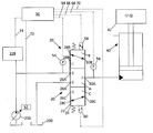
도 2는 도 1에 나타낸 작업 머신에서 사용하기 적합한 유압 회로의 부분을 개략적으로 나타낸 도면이다.
도 3은 도 2에 나타낸 유압 회로에 대한 전자 제어 시스템의 개략적인 도면이다.
도 4는 도 2에 나타낸 작업 회로의 동작의 방법을 나타낸 처리 흐름도이다.
도 5는 도 2에 나타낸 작업 회로의 동작의 방법을 나타낸 처리 흐름도이다.Non-limiting and general embodiments are described with reference to the following drawings, which, regardless of scale, the same reference numerals refer to the same parts from various points of view, unless otherwise specified.
1 is a schematic illustration of a working machine having a form that is an example of a side according to the principles of the present disclosure.
FIG. 2 is a schematic representation of a portion of a hydraulic circuit suitable for use in the work machine shown in FIG. 1.
FIG. 3 is a schematic diagram of an electronic control system for the hydraulic circuit shown in FIG. 2.
FIG. 4 is a process flowchart showing a method of operation of the working circuit shown in FIG. 2.
FIG. 5 is a process flowchart showing a method of operation of the working circuit shown in FIG. 2.
다양한 실시형태가 이하 도면을 참조로 상세히 설명되는데, 다수의 도면을 통해서 동일 부분 및 어셈블리는 동일 참조부호로 나타낸다. 다양한 실시형태의 참조는, 첨부된 청구항들의 범위를 제한하지 않는다. 더욱이, 본 명세서에서 설명된 소정의 예는 첨부된 청구항에 대한 많은 가능한 실시형태 중 몇몇을 설명하기 위한 것으로 이에 제한되지 않는다. Various embodiments are described in detail below with reference to the drawings, wherein like reference numerals refer to like parts and assemblies throughout the several views. Reference to various embodiments does not limit the scope of the appended claims. Moreover, certain examples described herein are intended to illustrate some of the many possible embodiments of the appended claims and are not limited thereto.
일반적인 설명General description
도 1에 묘사된 바와 같은 작업 머신(200)이 보인다. 작업 머신(200)은 다양한 작업 임무를 수행하기 위한 작업 부가 장치(202)를 포함한다. 일 실시형태에 있어서, 작업 머신(200)은 포크 리프트 트럭이고, 작업 부가 장치(202)는 2개의 포크를 포함하여 구성된다. 그런데, 본 기술 분야의 당업자는 작업 부가 장치가 소정의 유압으로 파워를 갖는 작업 도구일 수 있는 것으로 이해한다. A
또한, 작업 머신(200)은 적어도 하나의 드라이브 휠(204)과 적어도 하나의 스티어 휠(206: steer wheel)을 포함하는 것으로 보인다. 소정 실시형태에 있어서, 하나 이상의 드라이브 휠(204)은 하나 이상의 스티어 휠(206)과 결합될 수 있다. 드라이브 휠은 펌프(210 및 212)와 유체 교통하는 엔진(208)에 의해 파워를 갖는다. 펌프(210)는 기계적으로 엔진(208)에 결합되는 한편, 펌프(212)는 유압 시스템(214)을 통해 엔진(208)에 접속된다. 또한, 펌프(212)는, 액슬(216: axles), 차동 장치(218) 및 드라이브 샤프트(220)를 통해 드라이브 휠(204)에 기계적으로 결합된다.
또한, 작업 회로(222) 및 스티어링 회로(224)는 유압 시스템(214)과 유체 교통한다. 작업 회로(222)는 작업 부가 장치(22)를 가동시켜서 작업 임무가 수행될 수 있도록 하는 한편, 스티어링 회로(224)는 작업 머신(200)이 요구 방향으로 선택적으로 스티어링되게 한다.
작업 회로Work circuit
도 2를 참조하면, 유압 시스템의 작업 회로(222) 및 다른 구성요소의 예가 보인다. 작업 회로(222)는 작업 머신(200)의 작업 부가 장치(202)를 가동시키기 위한 것이다. 작업 회로(222)는, 부가 장치 리프트 기능과 같은 작업 기능을 가능하게 하기 위한 제1밸브 어셈블리(20)를 포함한다. 또한, 작업 회로(222)는, 유압 시스템(214) 내의 다른 기능을 가능하게 하기 위한 복수의 추가적인 밸브 및/또는 유체 파워 소비 구성요소(228)를 포함할 수 있다. 개시된 특정 실시형태에 있어서, 제1밸브 어셈블리(20)는 스플(24)이 배치된 슬리브(22)를 갖는 비례 밸브이다. 2, examples of working
제1밸브 어셈블리(20)는, 펌프(210)로부터 가압된 유체를, 작업 부가 장치(202)에 기계적으로 결합될 수 있는 하나 이상의 유압 액튜에이터(40)에 선택적으로 제공하도록 구성 및 배열된다. 용어 "유압 액튜에이터"의 사용은, 유압 실린더(예를 들어, 리프트 실린더), 유압 모터 등의 사용을 의미한다. 도 2에 나타낸 예시적인 실시형태에 있어서, 유압 액튜에이터(40)는 유압의 리프트 실린더이다. 제1밸브 어셈블리(20)의 동작은, 작업 부가 장치(202)가 작업 기능에서 선택적으로 가동되게 한다. 유압 액튜에이터(40)의 가동 속도는 제1밸브 어셈블리(20)를 통한 흐름의 결과이다. 제1밸브 어셈블리(20)를 통한 흐름은 밸브(20)의 스플(24)의 각각의 단부에서 작용하는 한 쌍의 가변 솔레노이드 액튜에이터(58, 60)에 의해 제어될 수 있다. 가변 솔레노이드 액튜에이터(58, 60)는 제어 라인(66, 70) 각각을 통해 제어 시스템(50)에 의해 동작될 수 있다.The
보이는 바와 같이, 제1밸브 어셈블리(20)는 펌프(210)와 탱크 저장소(230) 및 유압 액튜에이터(40)와 유체 교통하는 3-위치, 3-웨이 밸브이다. 본 기술 분야의 당업자는 단일의 3-웨이 밸브(20) 대신 2개의 밸브가 사용될 수 있는 것으로 인식한다. 한편, 단일의 밸브는, 도 1에 일반적으로 나타낸 바와 같이, 유압 액튜에이터에 동시에 들어가고 나오는 유체를 제어하는데 사용될 수 있다. 이러한 접근에 있어서, 하나의 밸브는 펌프(210)와 유압 액튜에이터(40)를 유체 교통하게 하는 한편, 제2밸브는 탱크 저장소(230)와 유압 액튜에이터(40)를 유체 교통하게 한다. 나타낸 실시형태에 있어서, 제1밸브 어셈블리(20)는 폐쇄 또는 중립 위치 A로부터 작업 위치 B로 그리고, 하강 위치 C로 이동 가능하다.As can be seen, the
폐쇄 위치 A에서, 포트 26A, 28A 및 30A는 폐쇄되어 펌프(210) 및 탱크 저장소(230) 모두가 유압 액튜에이터(40)로부터 차폐된다. 이 위치에 있어서, 작업 부가 장치(202)는 정지 위치이고 상승 또는 하강할 수 없다. In the closed position A,
작업 위치 B에서, 제1밸브 어셈블리(20)는 포트 26B 및 30B가 서로 유체 교통하게 위치되도록 위치된다. 이 위치는 펌프(210)가 유압 액튜에이터(40)와 유체 교통하도록 허용한다. 펌프 압력이 부하(42)에 의해 유도된 압력을 초과하는 곳에서, 유압 액튜에이터는 부하(42)가 상승하게 한다. 작업 위치에서, 탱크 저장소(230)는 포트 28B를 막는다.In working position B, the
하강 위치 C에서, 제1밸브 어셈블리(20)는, 포트 28C 및 30C가 서로 유체 교통하게 위치되도록 위치된다. 이 위치는 탱크 저장소(230)가 유압 액튜에이터(40)와 유체 교통하는 위치로 되게 허용한다. 하강 위치 C는 유체가 유압 액튜에이터(40)로부터 탱크 저장소(230)로 유출되어, 부하(42)가 하강하게 한다. In the lowered position C, the
또한, 작업 회로(222)는, 유압 액튜에이터(40)와 제1밸브 어셈블리(20) 사이에 배치된 제1압력 센서(56)를 갖는 것으로 보인다. 이 센서는 제어 라인(68)을 통해서 전자 제어기(50)와 통신하게 위치된다. 제1압력 센서(56)는 제어기(50)에 유압 액튜에이터(40) 내의 압력에 대한 입력을 제공한다. 제1밸브 어셈블리(20)가 폐쇄 위치일 때, 제1압력 센서(56)는 부하(42)에 의해 시스템 상에 유도된 압력에 대한 표시를 제공한다. The working
또한, 작업 회로(222)는 펌프(210)와 제1밸브 어셈블리(20) 사이에 배치된 제2압력 센서(54)를 갖는 것으로 보인다. 이 센서는 제어 라인(64)을 통해 전자 제어기(50)와 통신하게 위치된다. 제2압력 센서(54)는 제어기(50)에 펌프(210)에 의해 생성된 압력에 대한 입력을 제공한다. 펌프 출력 압력은 제어 라인(72)을 통해 전자 제어기(50)와 통신하는 펌프 제어기(52)에 의해 제어될 수 있다. The working
보이는 실시형태에 있어서, 다른 제어 밸브 또는 압력 소비 장치(228)가 작업 회로(222)의 부분이 되거나 되지 않을 수 있다. 또한, 이들 장치(228)는 제어 라인(74)을 통해 전자 제어기(50)와 통신하게 위치될 수 있다. In the embodiment shown, other control valves or
전자 제어 시스템 Electronic control system
유압 시스템(214)은 작업 머신(200) 상에 (예를 들어, 오퍼레이터에 의해) 위치되는 요구에 의존해서 다양한 모드에서 동작한다. 전자 제어 시스템은 다양한 모드가 적합한 시간에 개시되게 감시 및 허용한다. The
전자 제어기(50)는 가장 적합한 모드로 유압 시스템(214)을 구성하기 위해서, 유압 시스템(214)의 다양한 센서 및 동작 파라미터를 감시한다. 이 모드는, 작업 회로 작업 모드 및 작업 회로 대기 모드를 포함한다.The
도 3을 참조하면, 전자 제어기(50)는 프로세서(50A) 및 RAM, 플래시 드라이브 또는 하드 드라이브와 같은 넌-트랜전트 기억 매체 또는 메모리(50B)를 포함하는 것으로 개략적으로 보인다. 메모리(50B)는 실행 가능한 코드, 동작 파라미터, 오퍼레이터 인터페이스로부터의 입력을 기억하기 위한 것이며, 프로세서(50A)는 코드를 실행하기 위한 것이다. 또한, 전자 제어기(50)는 작업 회로 작업 모드와 작업 회로 대기 모드를 실행하기 위해 사용될 수 있는 다수의 입력 및 출력을 갖는 것으로 보인다. 상기된 바와 같이, 입력 중 하나는 압력 센서(52)에 의해 제공된 측정된 펌프 출력 압력(100)이다. 다른 입력은 압력 센서(56)에 의해 제공된 측정된 유압 액튜에이터 압력(102)이다. 본 기술 분야의 당업자는 많은 다른 입력이 가능한 것으로 이해한다. 예를 들어, 측정된 엔진 속도는 전자 제어기(50)로의 직접 입력으로서 제공되고, CAN(control area network)을 통해 제어 시스템의 다른 부분으로부터 수신될 수 있다. 예를 들어, 변위 피드백 센서를 통한 측정된 펌프 변위가 제공될 수도 있다. Referring to FIG. 3, the
전자 제어기(50) 내로의 다른 입력은, 작업 레버(62)로부터의 레버 위치 입력(104)이다. 일 실시형태에 있어서, 레버 위치 입력은 리프팅 레버와 같은 전자 레버로부터의 직접 디지털 신호이다. 작업 레버(62)는, 유압 액튜에이터(40)에 의한 부하 작업 동작이 요구되는 사용자 표시를 제어기(50)에 제공한다. Another input into the
도 3을 더 참조하면, 전자 제어기(50)로부터의 다수의 출력이 보인다. 하나의 출력은 펌프 출력 명령(106)인데, 이는 펌프(102)의 출력 압력을 조정하기 위한 것이다. 일 실시형태에 있어서, 펌프 압력 출력은 가변 변위 축의 피스톤 펌프에서 경사 판(swash plate)의 각도를 조정함으로써 제어될 수 있다. 또 다른 출력은 밸브 위치 명령(108)이다. 보이는 특정 실시형태에 있어서, 밸브 명령 출력(108)은 제어 라인(66, 70)을 통한 제어 밸브(20)의 솔레노이드 밸브(58, 60)에 대한 비례 신호이다. 추가적인 밸브 출력 위치 명령이 제어기(50)로부터 장치(228)로 보내질 수 있다. With further reference to FIG. 3, a number of outputs from the
또한, 전자 제어기(50)는, 제어기(502)의 입력과 출력을 상관하기 위해서, 다수의 맵(map) 또는 알고리즘을 포함할 수 있다. 예를 들어, 제어기(502)는 센서(54 및 56)에서 측정된 압력에 기반해서, 제1밸브 어셈블리(20)의 펌프 출력 압력 및 위치를 제어하기 위한 알고리즘을 포함할 수 있다. 일 실시형태에 있어서, 제어기(50)는, 이하 동작 방법의 섹션에서 더 개시된 바와 같이, 작업 모드와 작업 대기 모드에서 시스템을 제어하기 위한 알고리즘을 포함한다. The
또한, 전자 제어기(50)는, 각각의 모드가 개시 및/또는 종료될 때를 결정하기 위해, 다수의 사전에 규정된 및/또는 구성 가능한 파라미터 및 오프셋을 기억할 수 있다. 본 명세서에서, 용어, "구성 가능한(configurable)"은, 제어기(예를 들어, 딥스위치(dipswitch))에서 선택되거나 또는 제어기 내에서 조정될 수 있는 파라미터 또는 오프셋 값에 대해서 언급한다. In addition, the
동작의 방법Method of Operation
도 4를 참조하면, 펌프(210) 및 제어 밸브 어셈블리(20)를 동작하는 방법(1000)이 보인다. 도 4가 특정 순서로 방법 단계를 도해해서 나타내지만, 이 방법은 나타낸 순서로 수행되는 것에 한정되지 않는다. 게다가, 적어도 몇몇 나타낸 단계는 겹치는 방법, 다른 순서 및/또는 동시에 수행될 수 있다. Referring to FIG. 4, a
방법(1000)의 제1단계 1002에서, 전자 제어기(50)는, 동작의 작업 모드가 요구되는 표시를 사용자로부터 수신한다. 이 표시는 다양한 사용자 입력으로부터 들어올 수 있다. 예를 들어, 사용자는 유압 액튜에이터(40)와 연관된 레버를 이동할 수 있다. 다른 예는, 사용자가 모드를 직접 선택하거나 또는 제어 시스템(500)의 사용자 인터페이스의 사용을 통해 간접적으로 선택한다. 단순화를 위해서, 시스템은 단계 1002에서 작업 대기 모드로 될 수 있는데, 여기서 제1제어 밸브 어셈블리는 폐쇄 또는 중립 위치로 있고, 펌프 압력은 측정된 유압 액튜에이터 유압 압력에 독립적인 값으로 제어된다. 이와 같이, 작업 대기 모드에서, 제어 시스템은, 사용자가 작업 레버를 작업 위치로 이동했더라도, 펌프가 풀 압력 출력 동작 상태로 명령되는 것을 방지한다. In a
제2단계 1004에서, 전자 제어기(50)는, 예를 들어 압력 센서(56)로부터 측정된 유압 액튜에이터 압력을 수신한다. 부하가 이미 작업 도구(202) 상에 위치되는 곳에서, 이 압력은 부하(42)에 의해 야기된 유도된 압력에 대응한다. In a
제3단계 1006에 있어서, 결정이 측정된 유압 액튜에이터 압력이 제1최대 압력 한계 값 이하인 지에 관해서 행해진다. 일 실시형태에 있어서, 제1최대 압력 한계 값은 최대 허용된 펌프 압력 한계와 동등하다. 일 실시형태에 있어서, 제1최대 압력 한계 값은 제1오프셋 값과 합산된 최대 허용된 펌프 압력 한계와 동등하다. 일 실시예에 있어서, 제1오프셋 값은 제로로 설정된다. 제1최대 압력 한계 값과 제1오프셋 값 모두는 제어기(50) 내에서 구성 가능하며, 그 값이 시스템의 최상의 수행을 위해 조정되고 최적화될 수 있도록 한다. In a
측정된 유압 액튜에이터 압력이 제1최대 압력 한계 값 이하가 아니면, 프로세스는 시스템이 작업 대기 모드로 남아 있는 시작으로 복귀한다. 이 상태는, 부하(42)가 펌프(210)가 극복하기 너무 큰 유도된 압력을 가지는 곳에서 존재하게 된다. 이와 같이, 에너지 소모가 있게 되는, 펌프가 최대 압력 출력하도록 명령하기보다, 시스템은 부하 리프트 동작이 요구되는 표시에 응답하지 않는다. 작업 대기 모드에 있어서, 펌프는 유압 액튜에이터에 대해 요구된 압력에 독립적으로 대신 동작한다. If the measured hydraulic actuator pressure is not below the first maximum pressure limit value, the process returns to the beginning where the system remains in work standby mode. This condition is present where the
측정된 유압 액튜에이터가 제1최대 압력 한계 값 이하이면, 프로세스는 단계 1008로 진행하는데, 여기서 작업 모드가 개시된다. 작업 모드에서, 펌프는 측정된 유압 액튜에이터 유압 압력보다 큰 출력 압력 값을 생성하기 위해서 명령을 받는다. 펌프 압력이 이 값에 도달하면, 제어 밸브는 작업 위치로 개방되어, 유압 액튜에이터와 펌프(210)가 서로 유체 교통하게 위치되도록 한다. 일 실시형태에 있어서, 펌프 출력 압력 값은, 센서(56)에서 측정됨에 따라, 제3오프셋 값과 합산된 유압 액튜에이터 압력으로서 규정된다. 일례에 있어서, 제3오프셋 값은 대략 10 bar이다. 제3오프셋 값은 제어기(50) 내에서 구성 가능하여, 그 값이 시스템의 최상의 수행을 위해 조정되고 최적화될 수 있도록 한다.If the measured hydraulic actuator is less than or equal to the first maximum pressure limit value, the process proceeds to step 1008, where a work mode is initiated. In the working mode, the pump is commanded to produce an output pressure value that is greater than the measured hydraulic actuator hydraulic pressure. When the pump pressure reaches this value, the control valve opens to the working position, allowing the hydraulic actuator and the
단계 1010에서, 제2결정이 측정된 유압 액튜에이터 압력이 제2최대 압력 한계 값 이상인지에 관해서 행해진다. 일 실시형태에 있어서, 제2최대 압력 한계 값은 최대 허용된 펌프 압력 한계와 동등하다. 일 실시형태에 있어서, 제2최대 압력 한계 값은, 제2오프셋 값과 합산된 최대 허용된 펌프 압력 한계와 동등하다. 일례에 있어서, 제2오프셋 값은 대략 5 bar이다. 제2오프셋 값은 제어기(50) 내에 구성 가능할 수 있으며, 그 값이 시스템의 최상의 수행을 위해 조정되고 최적화될 수 있도록 한다. In
측정된 유압 액튜에이터 압력이 제2최대 압력 한계 값 이하이면, 제어기는 시스템이 작업 모드를 유지하게 하고, 프로세스는 단계 1008로 복귀하게 허용한다. 그런데, 측정된 유압 액튜에이터 압력이 제2최대 압력 한계 값 이상이면, 시스템은 단계 1012에서 작업 대기 모드로 복귀한다. 상기한 바와 같이, 작업 대기 모드는 밸브가 폐쇄되어, 펌프와 유압 액튜에이터가 서로 차폐되도록 하고, 펌프 압력 출력은 대기 압력 또는, 그렇지 않으면 유압 액튜에이터의 요구 조건에 독립적으로 동작하는 압력으로 설정되도록 한다. If the measured hydraulic actuator pressure is below the second maximum pressure limit value, the controller allows the system to remain in working mode and the process returns to step 1008. However, if the measured hydraulic actuator pressure is above the second maximum pressure limit value, the system returns to the work standby mode in
도 5를 참조하면, 펌프(210) 및 제어 밸브 어셈블리(20)를 동작하는 제2방법(1100)이 보인다. 도 5가 특정 순서로 방법 단계를 도해해서 나타내지만, 이 방법은 나타낸 순서로 수행되는 것에 한정되지 않는다. 게다가, 적어도 몇몇 나타낸 단계는 겹치는 방법, 다른 순서 및/또는 동시에 수행될 수 있다. 많은 단계들이 방법(1000)에 대해서 개시된 것과 유사한 형태를 포함하에 따라, 방법(1000)에 대한 개시 내용의 실체가 참조로 방법(1100)에 대한 설명에 참조로 통합된다. Referring to FIG. 5, there is shown a
단계 1102 및 1104는 방법(1000)의 단계 1002 및 1004와 동일하며, 그러므로 이하 더 상세히 논의한다.
단계 1106에서, 오프셋 값과 측정된 리프트 실린더 압력을 합산함으로써, 펌프 압력 요구 값이 계산된다. 일 실시형태에 있어서, 오프셋 값은 대략 10 bar이다.In
단계 1108에서, 펌프 압력 요구 값과 최대 허용된 펌프 압력 한계 값 마이너스 제2오프셋 값 사이의 비교가 행해진다. 일 실시형태에 있어서, 제2오프셋 값은 대략 5 bar이다. 펌프 압력 요구 값이 펌프 압력 한계 마이너스 제2오프셋 값 미만이면, 회로는 단계 1108에서 작업 모드에 위치된다. 그렇지 않으면, 회로는 작업 대기 모드를 유지하고, 프로세스는 단계 1102로 복귀한다. In
단계 1110에서, 펌프는 펌프 압력 요구 값을 달성하도록 명령을 받고, 제어 밸브는 작업 위치로 개방되어, 펌프와 유압 액튜에이터가 서로 유체 교통하게 위치되도록 한다. In
단계 1112에서, 펌프 압력 요구 값과 최대 허용된 펌프 압력 사이의 제2비교가 행해진다. 펌프 압력 요구 값이 펌프 압력 한계 미만이면, 회로는 작업 모드 내에 유지되도록 계속되고, 프로세스는 단계 1110으로 복귀한다. 펌프 압력 요구 값이 펌프 압력 한계보다 크면, 회로는 작업 모드로부터 벗어나 단계 1114에서 대기 모드에 위치된다.In
단계 1114에서, 밸브는 중립 위치로 폐쇄되어 펌프와 유압 액튜에이터가 서로 차폐된다. 또한, 펌프 압력은 구성 가능한 대기 압력과 동등한 공급 압력 요구로 설정되거나, 시스템 내의 다른 구성요소를 충족하기에 충분한 압력과 동등하게 설정하거나 또는, 그렇지 않으면 유압 액튜에이터 압력에 독립적인 값으로 설정된다. In
인식되는 바와 같이, 상기된 프로세스 및 연관된 개시 내용은, 펌프가 리프팅 동작과 같은 작업 동작에 요구되는 압력을 실재적으로 생산할 수 있기 전에 미리 이를 확신할 수 있을 때, 출력 압력을 증가하도록 펌프에 명령하는 것만으로, 시스템이 펌프를 더 경제적인 방식으로 동작하게 한다. As will be appreciated, the above-described process and associated disclosures instruct the pump to increase the output pressure when it can be convinced in advance before the pump can actually produce the pressure required for a working operation such as a lifting operation. Just make the system operate the pump in a more economical way.
상기된 다양한 실시형태가 첨부된 청구항을 제한하지 않고, 예시적으로 제공되었다. 본 기술 분야의 당업자는 다양한 변형 및 변경이 본 개시 내용의 정신 및 범위로부터 벗어남이 없이 가능한 것으로 인식한다. The various embodiments described above are provided by way of example and not limitation of the appended claims. Those skilled in the art will recognize that various modifications and changes are possible without departing from the spirit and scope of the present disclosure.
20 - 밸브 어셈블리,
40 - 유압 액튜에이터,
50 - 전자 제어기,
40 - 유압 액튜에이터.20-valve assembly,
40-hydraulic actuator,
50-electronic controller,
40-hydraulic actuator.
Claims (27)
(a) 작업 동작이 유압 회로 내에서 작업 레버에 의해 요구되는 표시를 수신하는 단계와;
(b) 측정된 유압 액튜에이터 유압 압력을 수신하는 단계와;
(c) 측정된 유압 액튜에이터 유압 압력이 제1최대 압력 한계 값 이하일 때, 작업 모드 내에 유압 회로를 위치시키는 단계로서, 작업 모드가:
i. 펌프와 유압 액튜에이터가 서로 유체 교통하도록 제어 밸브를 작업 위치로 이동하는 단계와;
ii. 측정된 유압 액튜에이터 유압 압력이 최대 압력 한계 이하일 때, 측정된 유압 액튜에이터 유압 압력보다 큰 출력 압력 값을 생성하도록 펌프에 명령하는 단계를 포함하는, 위치시키는 단계와;
(d) 측정된 유압 액튜에이터 유압 압력이 최대 압력 한계 값 이상일 때, 유압 회로를 대기 모드로 위치시키는 단계로서, 대기 모드가:
i. 펌프가 유압 액튜에이터로부터 차폐되도록 제어 밸브를 폐쇄 위치로 이동시키는 단계와;
ii. 측정된 유압 액튜에이터 유압 압력에 독립적인 출력 압력 값을 생성하도록 펌프에 명령하는 단계를 포함하는, 위치시키는 단계를 포함하여 구성되는 것을 특징으로 하는 방법. A method of controlling a hydraulic circuit having a pump and a hydraulic actuator and a control valve disposed between the pump and the hydraulic actuator:
(a) receiving an indication that a work operation is required by the work lever in the hydraulic circuit;
(b) receiving the measured hydraulic actuator hydraulic pressure;
(c) when the measured hydraulic actuator hydraulic pressure is below the first maximum pressure limit value, positioning the hydraulic circuit in the working mode, wherein the working mode is:
i. Moving the control valve to a working position such that the pump and the hydraulic actuator are in fluid communication with each other;
ii. Positioning the pump to produce an output pressure value that is greater than the measured hydraulic actuator hydraulic pressure when the measured hydraulic actuator hydraulic pressure is below the maximum pressure limit;
(d) placing the hydraulic circuit in standby mode when the measured hydraulic actuator hydraulic pressure is above the maximum pressure limit value, the standby mode being:
i. Moving the control valve to the closed position such that the pump is shielded from the hydraulic actuator;
ii. And positioning the pump to produce an output pressure value independent of the measured hydraulic actuator hydraulic pressure.
제1최대 압력 한계 값은 허용 가능한 최대 허용된 펌프 압력 한계를 포함하는 것을 특징으로 하는 방법. The method of claim 1,
And the first maximum pressure limit value comprises an allowable maximum allowed pump pressure limit.
제1최대 압력 한계는 제1오프셋 값과 합산된 최대 허용된 펌프 압력 한계를 포함하는 것을 특징으로 하는 방법. 3. The method of claim 2,
And the first maximum pressure limit comprises a maximum allowed pump pressure limit summed with the first offset value.
제2최대 압력 한계 값은 허용 가능한 최대 허용된 펌프 압력 한계를 포함하는 것을 특징으로 하는 방법. The method of claim 1,
And the second maximum pressure limit value comprises an allowable maximum allowed pump pressure limit.
제1최대 압력 한계는 제2오프셋 값과 합산된 최대 허용된 펌프 압력 한계를 포함하는 것을 특징으로 하는 방법. 5. The method of claim 4,
Wherein the first maximum pressure limit comprises a maximum allowed pump pressure limit summed with a second offset value.
제1최대 압력 한계는 제2오프셋 값과 합산된 최대 허용된 펌프 압력 한계를 포함하는 것을 특징으로 하는 방법.The method of claim 3,
Wherein the first maximum pressure limit comprises a maximum allowed pump pressure limit summed with a second offset value.
제1오프셋 값은 대략 0 bar이고, 제2오프셋 값은 대략 5 bar인 것을 특징으로 하는 방법.The method according to claim 6,
And the first offset value is approximately 0 bar and the second offset value is approximately 5 bar.
작업 모드의 펌프의 출력 압력 값이 제3오프셋 값과 합산된 측정된 유압 액튜에이터 유압 압력과 동등하게 설정되는 것을 특징으로 하는 방법.The method of claim 1,
The output pressure value of the pump in the working mode is set equal to the measured hydraulic actuator hydraulic pressure summed with the third offset value.
(a) 전자 제어기와;
(b) 적어도 하나의 유압 액튜에이터와;
(c) 전자 제어기와 통신하는 유압 펌프와;
(d) 전자 제어기와 통신하고, 펌프와 유압 액튜에이터 사이에 배치되고, 폐쇄 위치로부터 유압 액튜에이터와 유압 펌프가 서로 유체 교통으로 위치되는 작업 위치로 이동 가능한 제어 밸브와;
(e) 전자 제어기와 통신하고, 제어 밸브와 유압 액튜에이터 사이에서 유압 압력을 측정하기 위한 제1압력 센서와;
(f) 전자 제어기와 통신하고, 펌프와 제어 밸브 사이의 유압 압력을 측정하기 위한 제2압력 센서와;
(g) 작업 모드와 작업 대기 모드 사이에서 시스템을 동작시키도록 구성되는 전자 제어기로서, 작업 모드는, 제1압력 센서에서의 유압 압력이 제1최대 압력 한계 값 이하일 때 개시되고, 작업 대기 모드는, 제1압력 센서에서의 유압 압력에서의 유압 압력이 제2최대 압력 한계 값 이상일 때 개시되는, 전자 제어기를 포함하여 구성되고;
(h) 작업 모드는:
i. 제어 밸브가 작업 위치;
ii. 펌프가 측정된 유압 액튜에이터 유압 압력보다 큰 출력 압력 값을 생성하도록 설정되는 것을 포함하고;
(i) 작업 대기 모드는:
i. 제어 밸브가 폐쇄 위치;
ii. 펌프가 측정된 유압 액튜에이터 유압 압력에 독립적인 출력 압력 값을 생성하도록 설정되는 것을 포함하는 것을 특징으로 하는 방법.As a hydraulic system for use in mobile vehicles:
(a) an electronic controller;
(b) at least one hydraulic actuator;
(c) a hydraulic pump in communication with the electronic controller;
(d) a control valve in communication with the electronic controller, the control valve being disposed between the pump and the hydraulic actuator, the control valve being movable from a closed position to a working position in which the hydraulic actuator and the hydraulic pump are located in fluid communication with each other;
(e) a first pressure sensor in communication with the electronic controller and for measuring hydraulic pressure between the control valve and the hydraulic actuator;
(f) a second pressure sensor in communication with the electronic controller and for measuring hydraulic pressure between the pump and the control valve;
(g) an electronic controller configured to operate the system between a work mode and a work standby mode, wherein the work mode is initiated when the hydraulic pressure at the first pressure sensor is less than or equal to the first maximum pressure limit value; And an electronic controller, initiated when the hydraulic pressure at the hydraulic pressure at the first pressure sensor is greater than or equal to the second maximum pressure limit value;
(h) The working mode is:
i. Control valve working position;
ii. The pump is set to produce an output pressure value that is greater than the measured hydraulic actuator hydraulic pressure;
(i) The job standby mode is:
i. Control valve closed position;
ii. And the pump is set to produce an output pressure value that is independent of the measured hydraulic actuator hydraulic pressure.
제1최대 압력 한계 값은 허용 가능한 최대 허용된 펌프 압력 한계를 포함하는 것을 특징으로 하는 방법. 10. The method of claim 9,
And the first maximum pressure limit value comprises an allowable maximum allowed pump pressure limit.
제1최대 압력 한계는 제1오프셋 값과 합산된 최대 허용된 펌프 압력 한계를 포함하는 것을 특징으로 하는 방법. The method of claim 10,
And the first maximum pressure limit comprises a maximum allowed pump pressure limit summed with the first offset value.
제2최대 압력 한계 값은 허용 가능한 최대 허용된 펌프 압력 한계를 포함하는 것을 특징으로 하는 방법. 10. The method of claim 9,
And the second maximum pressure limit value comprises an allowable maximum allowed pump pressure limit.
제1최대 압력 한계는 제2오프셋 값과 합산된 최대 허용된 펌프 압력 한계를 포함하는 것을 특징으로 하는 방법. The method of claim 12,
Wherein the first maximum pressure limit comprises a maximum allowed pump pressure limit summed with a second offset value.
제1최대 압력 한계는 제2오프셋 값과 합산된 최대 허용된 펌프 압력 한계를 포함하는 것을 특징으로 하는 방법.12. The method of claim 11,
Wherein the first maximum pressure limit comprises a maximum allowed pump pressure limit summed with a second offset value.
제1오프셋 값은 대략 0 bar이고, 제2오프셋 값은 대략 5 bar인 것을 특징으로 하는 방법.15. The method of claim 14,
And the first offset value is approximately 0 bar and the second offset value is approximately 5 bar.
작업 모드의 펌프의 출력 압력 값이 제3오프셋 값과 합산된 측정된 유압 액튜에이터 유압 압력과 동등하게 설정된 것을 특징으로 하는 방법.10. The method of claim 9,
The output pressure value of the pump in the working mode is set equal to the measured hydraulic actuator hydraulic pressure summed with the third offset value.
(a) 넌-트랜전트 기억 매체와;
(b) 프로세서와;
(c) 넌-트랜전트 기억 매체 상에 기억되고 프로세서에 의해 실행 가능한 제어 알고리즘과;
(d) 전자 제어기가 작업 모드와 작업 대기 모드 사이에서 유압 회로를 동작시키도록 구성되는 제어 알고리즘으로서, 작업 모드는, 유압 액튜에이터와 연관된 측정된 유압 압력이 제1최대 압력 한계 값 이하일 때 개시되고, 작업 대기 모드는, 측정된 유압 압력이 제2최대 압력 한계 값 이상일 때 개시되는, 제어 알고리즘을 포함하여 구성되고;
(e) 작업 모드는:
i. 제어 밸브가 작업 위치;
ii. 펌프가 측정된 유압 액튜에이터 유압 압력보다 큰 출력 압력 값을 생성하도록 설정되는 것을 포함하고;
(f) 작업 대기 모드는:
i. 제어 밸브가 폐쇄 위치;
ii. 펌프가 측정된 유압 액튜에이터 유압 압력에 독립적인 출력 압력 값을 생성하도록 설정되는 것을 포함하는 것을 특징으로 하는 전자 제어기.As an electronic controller for use in a hydraulic circuit having a pump and a hydraulic actuator and a control valve disposed between the pump and the hydraulic actuator:
(a) a non-transient storage medium;
(b) a processor;
(c) a control algorithm stored on the non-transient storage medium and executable by the processor;
(d) a control algorithm, wherein the electronic controller is configured to operate the hydraulic circuit between the working mode and the working standby mode, wherein the working mode is initiated when the measured hydraulic pressure associated with the hydraulic actuator is less than or equal to the first maximum pressure limit value; The work standby mode comprises a control algorithm, initiated when the measured hydraulic pressure is above the second maximum pressure limit value;
(e) The working mode is:
i. Control valve working position;
ii. The pump is set to produce an output pressure value that is greater than the measured hydraulic actuator hydraulic pressure;
(f) The job standby mode is:
i. Control valve closed position;
ii. And the pump is set to produce an output pressure value that is independent of the measured hydraulic actuator hydraulic pressure.
제1최대 압력 한계 값은 허용 가능한 최대 허용된 펌프 압력 한계를 포함하는 것을 특징으로 하는 방법. 18. The method of claim 17,
And the first maximum pressure limit value comprises an allowable maximum allowed pump pressure limit.
제1최대 압력 한계는 제1오프셋 값과 합산된 최대 허용된 펌프 압력 한계를 포함하는 것을 특징으로 하는 방법. 19. The method of claim 18,
And the first maximum pressure limit comprises a maximum allowed pump pressure limit summed with the first offset value.
제2최대 압력 한계 값은 허용 가능한 최대 허용된 펌프 압력 한계를 포함하는 것을 특징으로 하는 방법. 18. The method of claim 17,
And the second maximum pressure limit value comprises an allowable maximum allowed pump pressure limit.
제1최대 압력 한계는 제2오프셋 값과 합산된 최대 허용된 펌프 압력 한계를 포함하는 것을 특징으로 하는 방법. 21. The method of claim 20,
Wherein the first maximum pressure limit comprises a maximum allowed pump pressure limit summed with a second offset value.
제1최대 압력 한계는 제2오프셋 값과 합산된 최대 허용된 펌프 압력 한계를 포함하는 것을 특징으로 하는 방법.20. The method of claim 19,
Wherein the first maximum pressure limit comprises a maximum allowed pump pressure limit summed with a second offset value.
제1오프셋 값 및 제2오프셋 값은 제어기 내에 구성 가능한 것을 특징으로 하는 방법.The method of claim 22,
And the first offset value and the second offset value are configurable in the controller.
제1오프셋 값은 대략 0 bar이고, 제2오프셋 값은 대략 5 bar인 것을 특징으로 하는 방법.The method of claim 22,
And the first offset value is approximately 0 bar and the second offset value is approximately 5 bar.
작업 모드의 펌프의 출력 압력 값이 제3오프셋 값과 합산된 측정된 유압 액튜에이터 유압 압력과 동등하게 설정되는 것을 특징으로 하는 방법.18. The method of claim 17,
The output pressure value of the pump in the working mode is set equal to the measured hydraulic actuator hydraulic pressure summed with the third offset value.
제3오프셋 값이 제어기 내에 구성 가능한 것을 특징으로 하는 방법.26. The method of claim 25,
And the third offset value is configurable in the controller.
제3오프셋 값은 대략 10 bar인 것을 특징으로 하는 방법. The method of claim 26,
And the third offset value is approximately 10 bar.
Applications Claiming Priority (3)
| Application Number | Priority Date | Filing Date | Title |
|---|---|---|---|
| US201161441453P | 2011-02-10 | 2011-02-10 | |
| US61/441,453 | 2011-02-10 | ||
| PCT/US2012/024681 WO2012109558A1 (en) | 2011-02-10 | 2012-02-10 | Load sense control with standby mode in case of overload |
Publications (1)
| Publication Number | Publication Date |
|---|---|
| KR20140010042A true KR20140010042A (en) | 2014-01-23 |
Family
ID=45819267
Family Applications (1)
| Application Number | Title | Priority Date | Filing Date |
|---|---|---|---|
| KR1020137021724A KR20140010042A (en) | 2011-02-10 | 2012-02-10 | Load sense control with standby mode in case of overload |
Country Status (9)
| Country | Link |
|---|---|
| US (1) | US20120204549A1 (en) |
| EP (1) | EP2673515A1 (en) |
| JP (1) | JP2014506662A (en) |
| KR (1) | KR20140010042A (en) |
| CN (1) | CN103459860A (en) |
| BR (1) | BR112013020389A2 (en) |
| CA (1) | CA2826759A1 (en) |
| MX (1) | MX2013009261A (en) |
| WO (1) | WO2012109558A1 (en) |
Families Citing this family (4)
| Publication number | Priority date | Publication date | Assignee | Title |
|---|---|---|---|---|
| EP2804992B1 (en) * | 2012-01-20 | 2018-12-12 | Eaton Corporation | Electronic load drop protection for hydraulic fluid system |
| US10611403B2 (en) | 2015-06-23 | 2020-04-07 | Eaton Intelligent Power Limited | Steering device for construction/transport/farm machine |
| CN107100916B (en) * | 2017-06-20 | 2018-09-11 | 合肥一航机械科技股份有限公司 | A kind of lifting machine load control system |
| US11085532B2 (en) * | 2019-03-12 | 2021-08-10 | GM Global Technology Operations LLC | Method for controlling a hydraulic system |
Family Cites Families (9)
| Publication number | Priority date | Publication date | Assignee | Title |
|---|---|---|---|---|
| DE2164628C3 (en) * | 1971-12-24 | 1978-03-16 | Siegfried Dipl.-Ing. Dr.-Ing. 4930 Detmold Gross | Overload cut-off device for hydraulic lifting and lifting devices coupled in series. Adjustment mechanisms |
| JPS56139316A (en) * | 1980-01-07 | 1981-10-30 | Komatsu Ltd | Power loss reduction controller for oil-pressure type construction machine |
| FR2534643B1 (en) * | 1982-10-15 | 1986-12-26 | Bennes Marrel | LOAD STATE CONTROLLER WITH TORQUE CAPACITY LIMITER FOR A HYDRAULIC CIRCUIT, ESPECIALLY ON A CRANE |
| EP0708053A1 (en) * | 1994-08-26 | 1996-04-24 | Hiab Export A/S | Overload protection system for hydraulic boom cranes, especially of the type used on motor vehicles |
| US6662705B2 (en) * | 2001-12-10 | 2003-12-16 | Caterpillar Inc | Electro-hydraulic valve control system and method |
| SE521188C2 (en) * | 2002-02-11 | 2003-10-07 | Kalmar Ind Sverige Ab | Hydraulic system for a vehicle, a vehicle comprising such a hydraulic system and an additional unit for such a vehicle |
| US7779628B2 (en) * | 2007-05-10 | 2010-08-24 | Eaton Corporation | Hydraulic drive system with exiting from pumping and motoring |
| JP5453857B2 (en) * | 2009-03-11 | 2014-03-26 | 株式会社豊田自動織機 | Cargo handling vehicle |
| CN201442834U (en) * | 2009-06-19 | 2010-04-28 | 威海市怡和专用设备制造有限公司 | Overloading detection device of working platform |
-
2012
- 2012-02-10 WO PCT/US2012/024681 patent/WO2012109558A1/en active Application Filing
- 2012-02-10 US US13/370,948 patent/US20120204549A1/en not_active Abandoned
- 2012-02-10 CA CA2826759A patent/CA2826759A1/en not_active Abandoned
- 2012-02-10 JP JP2013553599A patent/JP2014506662A/en active Pending
- 2012-02-10 KR KR1020137021724A patent/KR20140010042A/en not_active Application Discontinuation
- 2012-02-10 MX MX2013009261A patent/MX2013009261A/en not_active Application Discontinuation
- 2012-02-10 BR BR112013020389A patent/BR112013020389A2/en not_active IP Right Cessation
- 2012-02-10 EP EP12708610.6A patent/EP2673515A1/en not_active Withdrawn
- 2012-02-10 CN CN2012800085189A patent/CN103459860A/en active Pending
Also Published As
| Publication number | Publication date |
|---|---|
| CN103459860A (en) | 2013-12-18 |
| JP2014506662A (en) | 2014-03-17 |
| EP2673515A1 (en) | 2013-12-18 |
| WO2012109558A1 (en) | 2012-08-16 |
| CA2826759A1 (en) | 2012-08-16 |
| BR112013020389A2 (en) | 2017-07-18 |
| MX2013009261A (en) | 2013-08-29 |
| US20120204549A1 (en) | 2012-08-16 |
Similar Documents
| Publication | Publication Date | Title |
|---|---|---|
| US10408238B2 (en) | Control strategy for hydraulic actuator with a pair of independent metering valves | |
| US7797934B2 (en) | Anti-stall system utilizing implement pilot relief | |
| US9382923B2 (en) | Load energy assist and horsepower management system | |
| US9932993B2 (en) | System and method for hydraulic energy recovery | |
| EP3505688B1 (en) | System for controlling construction machinery and method for controlling construction machinery | |
| EP3280847B1 (en) | A load sensing hydraulic system for a working machine, and a method for controlling a load sensing hydraulic system | |
| US9423800B2 (en) | Fail operational modes for an electro-hydraulic system | |
| KR20140010042A (en) | Load sense control with standby mode in case of overload | |
| EP2901025B1 (en) | Twin priority valve | |
| EP2635747A1 (en) | A method for controlling a hydraulic system of a working machine | |
| US20140033698A1 (en) | Meterless hydraulic system having force modulation | |
| US20140033697A1 (en) | Meterless hydraulic system having force modulation | |
| KR102411520B1 (en) | Low noise control algorithm for hydraulic systems | |
| US10662621B2 (en) | Control of variable gravity driven hydraulic loads | |
| EP3599382B1 (en) | Hydraulic system and method for controlling the speed and pressure of a hydraulic cylinder |
Legal Events
| Date | Code | Title | Description |
|---|---|---|---|
| WITN | Application deemed withdrawn, e.g. because no request for examination was filed or no examination fee was paid |