KR20130143574A - Connection device with releasable clamping modules - Google Patents
Connection device with releasable clamping modules Download PDFInfo
- Publication number
- KR20130143574A KR20130143574A KR1020137010595A KR20137010595A KR20130143574A KR 20130143574 A KR20130143574 A KR 20130143574A KR 1020137010595 A KR1020137010595 A KR 1020137010595A KR 20137010595 A KR20137010595 A KR 20137010595A KR 20130143574 A KR20130143574 A KR 20130143574A
- Authority
- KR
- South Korea
- Prior art keywords
- end part
- connection
- movement
- module
- flange
- Prior art date
Links
Images


Classifications
-
- F—MECHANICAL ENGINEERING; LIGHTING; HEATING; WEAPONS; BLASTING
- F16—ENGINEERING ELEMENTS AND UNITS; GENERAL MEASURES FOR PRODUCING AND MAINTAINING EFFECTIVE FUNCTIONING OF MACHINES OR INSTALLATIONS; THERMAL INSULATION IN GENERAL
- F16L—PIPES; JOINTS OR FITTINGS FOR PIPES; SUPPORTS FOR PIPES, CABLES OR PROTECTIVE TUBING; MEANS FOR THERMAL INSULATION IN GENERAL
- F16L37/00—Couplings of the quick-acting type
- F16L37/08—Couplings of the quick-acting type in which the connection between abutting or axially overlapping ends is maintained by locking members
- F16L37/12—Couplings of the quick-acting type in which the connection between abutting or axially overlapping ends is maintained by locking members using hooks, pawls or other movable or insertable locking members
-
- B—PERFORMING OPERATIONS; TRANSPORTING
- B63—SHIPS OR OTHER WATERBORNE VESSELS; RELATED EQUIPMENT
- B63B—SHIPS OR OTHER WATERBORNE VESSELS; EQUIPMENT FOR SHIPPING
- B63B27/00—Arrangement of ship-based loading or unloading equipment for cargo or passengers
- B63B27/24—Arrangement of ship-based loading or unloading equipment for cargo or passengers of pipe-lines
- B63B27/25—Arrangement of ship-based loading or unloading equipment for cargo or passengers of pipe-lines for fluidised bulk material
-
- B—PERFORMING OPERATIONS; TRANSPORTING
- B63—SHIPS OR OTHER WATERBORNE VESSELS; RELATED EQUIPMENT
- B63B—SHIPS OR OTHER WATERBORNE VESSELS; EQUIPMENT FOR SHIPPING
- B63B27/00—Arrangement of ship-based loading or unloading equipment for cargo or passengers
- B63B27/24—Arrangement of ship-based loading or unloading equipment for cargo or passengers of pipe-lines
-
- F—MECHANICAL ENGINEERING; LIGHTING; HEATING; WEAPONS; BLASTING
- F16—ENGINEERING ELEMENTS AND UNITS; GENERAL MEASURES FOR PRODUCING AND MAINTAINING EFFECTIVE FUNCTIONING OF MACHINES OR INSTALLATIONS; THERMAL INSULATION IN GENERAL
- F16L—PIPES; JOINTS OR FITTINGS FOR PIPES; SUPPORTS FOR PIPES, CABLES OR PROTECTIVE TUBING; MEANS FOR THERMAL INSULATION IN GENERAL
- F16L23/00—Flanged joints
- F16L23/02—Flanged joints the flanges being connected by members tensioned axially
- F16L23/036—Flanged joints the flanges being connected by members tensioned axially characterised by the tensioning members, e.g. specially adapted bolts or C-clamps
-
- F—MECHANICAL ENGINEERING; LIGHTING; HEATING; WEAPONS; BLASTING
- F16—ENGINEERING ELEMENTS AND UNITS; GENERAL MEASURES FOR PRODUCING AND MAINTAINING EFFECTIVE FUNCTIONING OF MACHINES OR INSTALLATIONS; THERMAL INSULATION IN GENERAL
- F16L—PIPES; JOINTS OR FITTINGS FOR PIPES; SUPPORTS FOR PIPES, CABLES OR PROTECTIVE TUBING; MEANS FOR THERMAL INSULATION IN GENERAL
- F16L37/00—Couplings of the quick-acting type
- F16L37/08—Couplings of the quick-acting type in which the connection between abutting or axially overlapping ends is maintained by locking members
- F16L37/12—Couplings of the quick-acting type in which the connection between abutting or axially overlapping ends is maintained by locking members using hooks, pawls or other movable or insertable locking members
- F16L37/1205—Couplings of the quick-acting type in which the connection between abutting or axially overlapping ends is maintained by locking members using hooks, pawls or other movable or insertable locking members using hooks hinged about an axis placed behind a flange and which act behind the other flange
-
- F—MECHANICAL ENGINEERING; LIGHTING; HEATING; WEAPONS; BLASTING
- F16—ENGINEERING ELEMENTS AND UNITS; GENERAL MEASURES FOR PRODUCING AND MAINTAINING EFFECTIVE FUNCTIONING OF MACHINES OR INSTALLATIONS; THERMAL INSULATION IN GENERAL
- F16L—PIPES; JOINTS OR FITTINGS FOR PIPES; SUPPORTS FOR PIPES, CABLES OR PROTECTIVE TUBING; MEANS FOR THERMAL INSULATION IN GENERAL
- F16L37/00—Couplings of the quick-acting type
- F16L37/62—Couplings of the quick-acting type pneumatically or hydraulically actuated
Abstract
본 발명은 제1 단부 부품(4.1) 및 제2 단부 부품(4.2) 그리고 다수의 클램핑 모듈(7)을 포함하고, 각각의 상기 모듈은 제2 단부 부품(4.2)의 플랜지(12)의 뒤에 고정되도록 또한 서로 멀어지도록 배치된다. 따라서 각각의 모듈(7)은, 제2 이동에서, 단부 부품들(4.1, 4.2)을 서로에 대해 고정할 수 있는 보유 위치로부터 이것을 더 이상 수행하지 않는 해제 위치까지 이동 가능하게 장착된다.The present invention comprises a first end part (4.1) and a second end part (4.2) and a plurality of clamping modules (7), each said module being fixed behind the flange (12) of the second end part (4.2) As far away from each other as possible. Each module 7 is thus movably mounted in a second movement from a holding position in which the end parts 4.1, 4.2 can be fixed relative to one another, to a release position in which it no longer does this.
Description
본 발명은 연결장치에 관한 것으로, 연결장치는 부유식 터미널과 같이 가스 터미널과 용기 사이로 연안(해상)에서 액화 천연 가스(LNG)를 이송시키기 위한 용도로 특히, 그러나 배타적이지는 않게 사용된다. 하나의 유체 운송 장치는 가스 터미널과의 연결이 가능한 LNG 연결-분리장치의 단부에서, 극저온 가요관으로 형성되고, 부유식 터미널로 지지된다.
The present invention relates to a connecting device, which is used in particular but not exclusively for the purpose of transferring liquefied natural gas (LNG) offshore (sea) between a gas terminal and a vessel, such as a floating terminal. One fluid transport device is formed as a cryogenic flexible tube at the end of an LNG connection-separator capable of connection with a gas terminal and supported by a floating terminal.
일반적인 의미의 LNG 연결-분리장치(또는 LNG 결합/해제장치)는 파이프라인의 두 부분 사이의 연결을 신속하게 분리시키는 것이 가능한 연결을 제공하기 위해 설계된 장치이다.In the general sense, an LNG connection-separator (or LNG coupling / disengagement device) is a device designed to provide a connection capable of quickly disconnecting a connection between two parts of a pipeline.
LNG 연결-분리장치는 두 용기들 사이의 연결을 가능하게 하는 클램핑 모듈을 포함하는 작동 연결-분리장치(일반적으로 QC/DC로 알려짐)를 포함하며, 또한 파이프라인이 두 개의 폐쇄부(일반적으로 ERS로 알려짐)로 분리되는 것을 가능하게 하는 비상분리 장치를 포함하고, 두 개의 분리 밸브를 포함하고, 상기 분리밸브들 사이에서 파이프라인이 칼라(collar) 개방부(일반적으로 ERC로 알려짐)를 관통하여 유체의 손실 없이 분리될 수 있다. 종래의 KSB사 및 Eurodim사에서 개발된 것과 같이(유럽 특허 제1405003호), 상기 ERS 장치는 특히 유체의 횡방향 유동 단면의 개방 위치와 폐쇄 위치 사이에서 피봇축 주위의 단부 내부에 피봇식으로 설치된 디스크를 각각 구비하는 두 개의 나비형 밸브 및 파이프라인의 축에 수직하게 연장되고 다른 하나와 평행한 피보팅(pivoting)을 조정하기 위한 외부 장치로 구성된다. 제1 나비형 밸브는 제1 단부 부품의 제1 단부에 설치되고, 제2 나비형 밸브는 제2 단부 부품의 단부에 설치되며, 두 나비형 밸브의 면들은 다른 하나와 마주하도록 전환된다. 상대적으로 가볍고 매우 밀집된다는 장점을 가진 이 장치는 폐쇄된 위치에서 두 나비형 밸브 사이의 매우 작은 부피로 인해 비상 분리 과정에서 유체의 아주 적은 손실만을 가능하게 한다. 이는 특히, 나비형 밸브의 이동 중의 나비형 밸브의 중첩 및 그것으로 인한 두 개의 조작 샤프트(manoeuvring shaft) 사이의 작은 거리를 특징으로 한다.The LNG connection-separator comprises an actuating connection-separator (commonly known as QC / DC) which includes a clamping module that enables the connection between two vessels, and the pipeline also has two closures (usually An emergency separation device that enables separation by means of ERS, comprising two separation valves, between which the pipeline passes through a collar opening (commonly known as ERC) Can be separated without loss of fluid. As developed by conventional KSB and Eurodim (European Patent No. 1405003), the ERS device is pivotally installed inside the end around the pivot axis, in particular between the open and closed positions of the transverse flow cross section of the fluid. It consists of two butterfly valves each having a disk and an external device for adjusting pivoting extending perpendicular to the axis of the pipeline and parallel to the other. The first butterfly valve is installed at the first end of the first end part, the second butterfly valve is installed at the end of the second end part, and the faces of the two butterfly valves are switched to face the other. The advantage of being relatively light and very compact is that the device allows only very little loss of fluid during the emergency separation due to the very small volume between the two butterfly valves in the closed position. This is especially characterized by the overlap of the butterfly valves during the movement of the butterfly valves and the resulting small distance between the two manoeuvring shafts.
공개되지 않은 프랑스 특허 출원 제10/01499호 및 제10/01500호는 이러한 ERS(ERC 칼라 없음)를 부피가 보다 작고 가벼운 형태의 연결-분리 장치로 사용하는 것을 개시하며, QC/DC와 ERS 장치를 같은 인터페이스로 재구성하며, 이것들은 통상의 연결-분리뿐만 아니라 비상분리까지 가능하게 하는 종래의 QC/DC 클램핑 모듈이다. 또한, 제3 나비형 밸브는 LNG 이송을 위해 필요한 가요성 파이프라인의 단부에 이중 밀봉 차단부를 가능하게 하기 위해 가요성 파이프라인의 단부 부품에 위치한다.The unpublished
그러나 이러한 클램핑 모듈들은 독립적으로서, 그들 중 하나에 결함이 발생한다면 연결-분리 장치의 두 단부 부품의 분리를 막을 수 있고, 이는 비상 분리 상황에서 위험할 수 있다. 또한, 비상 분리 장치는 활성화 이후 2초 안에 작동하여야 하며, 이는 복수의 클램핑 모듈로 구성된 장치에서 매우 달성하기 어렵다. 본 발명의 목적은 따라서 이러한 약점들을 극복하는 것이다.However, these clamping modules are independent and can prevent the separation of the two end parts of the connection-disconnect device if one of them fails, which can be dangerous in an emergency disconnect situation. In addition, the emergency disconnect device must operate within 2 seconds after activation, which is very difficult to achieve in a device consisting of a plurality of clamping modules. It is therefore an object of the present invention to overcome these weaknesses.
본 발명은 종래의 연결-분리 및 비상 분리 기능을 단일 인터페이스로 재구성하는 연결-분리 장치이고, 가스 터미널에 연결되는 제1 단부 부품 및 가요성 파이프라인에 연결되는 제2 단부 부품 그리고 다수의 클램핑 모듈을 포함하며, 각각의 모듈은 각각 제1 단부 부품 위에 지지체에 의해 설치되고, 작동 모드에서 연결의 개방 시에는 서로 멀어지도록 이동하고 연결의 폐쇄 시에는 상기 제2 단부 부품의 플랜지 뒤에 고정되도록 회전 구성요소와의 제1 이동을 따라 배치되고, 비상 모드에서는, 각각의 모듈은 보유 위치에 의해 고정되는, 단부 부품들을 서로에 대해 고정할 수 있는 곳의 보유 위치로부터 이것을 더 이상 수행하지 않는 해제 위치까지 제2 이동을 따라 이동 가능하게 장착되며, 제2 이동은 모듈과 제2 단부 부품의 방향을 따라 점점 더 단부 부품들의 축으로부터 그들을 제거하는 모듈의 지지체의 일괄적인 병진 운동인 것을 특징으로 한다.The present invention is a connection-separation device for reconfiguring conventional connection-disconnection and emergency disconnection functions into a single interface, a first end part connected to a gas terminal and a second end part connected to a flexible pipeline and a plurality of clamping modules. Each module is installed by a support on each of the first end parts, and configured to move away from each other when the connection is opened in the operating mode and to be fixed behind the flange of the second end part when the connection is closed Disposed in accordance with the first movement with the element, in the emergency mode, each module is secured by a retaining position from a retaining position where the end parts can be fixed relative to each other from a retaining position that no longer does this. Movably mounted along a second movement, the second movement being increasingly end portions along the direction of the module and the second end component. Characterized in that it is a batch translational movement of the support of the module to remove them from the axes of the arms.
본 발명에 따르면, 개방 위치에서, 비상 모드에서, 이러한 조립체 부분이 이동할 뿐만 아니라, 모듈도 지지체와 함께 단일 유닛으로 이동하고, 이러한 이동부 구획은 별개의 작동이 필요하여 고장의 원인이 된다.According to the invention, in the open position, in the emergency mode, not only this part of the assembly is moved, but also the module is moved together with the support in a single unit, and this moving compartment section requires a separate operation and causes a failure.
해상에서 유체가 이송되는 경우, 가요성 파이프라인에 의해 연결 시스템으로 전달되는 힘은 매우 중요할 수 있다.When fluid is transported at sea, the force delivered to the connection system by the flexible pipeline can be very important.
미국 특허 제3586350호(도 5)에서, 조오(jaw)(51)는 본체(15)의 플랜지(17)와의 관계에서 다른 플랜지(19)를 고정하는 모든 힘을 부담한다. 견인력 또는 가요성 모멘트의 경우에, 플랜지(19)는 다른 플랜지(17)로부터 이격되려는 경향이 있고, 조오(51)는 반시계 방향으로 그것의 피봇축(52) 주위에 피봇하려는 경향이 있다. 이는 조오(51)의 면(58)과 롤러(57) 사이의 매우 중요한 접촉력을 생성한다.In U. S. Patent No. 3586350 (FIG. 5), jaws 51 bear all the forces for securing the
비상 분리가 발생했다면, 피스톤(64)의 유압 공급원(hydraulic power supply)은 피스톤을 위로 구동하며, 반시계 방향으로 아암(53)의 피봇축(54) 주위로 아암(53)의 피보팅을 구동해야 하고, 따라서 조오(51)를 그것의 피봇축(52) 주위로 반시계 방향으로 회전하면서 해제하며, 이는 플랜지(19)의 해제를 가능하게 한다. 미국 특허 제3586350호는 피스톤(64)에 공급되는 유압이 조오(51)의 면(58)과 롤러(57) 사이의 마찰력을 극복하기에 충분해야 한다는 사실을 제시하고 있다.If an emergency disconnect has occurred, the hydraulic power supply of the piston 64 drives the piston upwards and must drive the pivoting of the arm 53 around the pivot axis 54 of the arm 53 in the counterclockwise direction. Thus, the jaw 51 is released while rotating counterclockwise around its pivot axis 52, which enables the release of the
그러나 상기 제시된 바와 같이, 이러한 접촉력은 매우 중요할 수 있고, 거친 바다에서 가요성 파이프라인을 통한 이송이 있는 때, 롤러(57)와 면(58) 사이의 오버 타임 매팅(over time matting)이 발생할 수 있다. 피스톤(64)은 또한 스프링(59)의 압축력을 극복해야 한다. 영하 163℃(-163℃)의 LNG(액화 천연 가스)를 이송할 때, 얼음이 생성될 수 있고 기구의 운동을 막을 수 있다.However, as suggested above, this contact force can be very important, and when there is transfer through the flexible pipeline in rough seas, over time matting between the roller 57 and the face 58 will occur. Can be. The piston 64 must also overcome the compressive force of the spring 59. When transporting LNG (liquefied natural gas) at minus 163 ° C. (−163 ° C.), ice may be produced and movement of the apparatus may be prevented.
이렇게 크게 세 가지 요인들이 비상 분리가 발생하는 것을 막는 장애를 조장하고, 가장 우선이 되는 설치의 안전성을 저해한다.These three major factors contribute to the obstacles that prevent emergency separation from occurring and undermine the safety of the first installation.
본 발명에 따르면, 클램핑 모듈은 냉기 밖으로 위치한(유체관으로부터 이격됨) 홈들과 리브(ribs)의 협동을 이용하여 전환된다. 가요성 파이프라인의 견인력은 분리를 용이하게 한다.(미국 특허 제3586350호에서는 반대가 된다.)According to the invention, the clamping module is switched using the cooperation of ribs with grooves located out of the cold air (separated from the fluid tube). The traction of the flexible pipeline facilitates separation (as opposed to US Patent No. 3586350).
양호하게, 보유 장치는 제1 단부 부품의 플랜지 위에서 각각의 모듈의 플랜지를 체결하는 모듈 모두에 통상적으로 쓰이는 클램핑 칼라를 포함하고, 제2 이동은 가요성 파이프라인의 본체 무게에 의해 발생되며, 상기 이동은 연결-분리 장치의 축의 횡방향에 대하여 상당한 경사각을 가능하게 하고, 제1 단부 부품은 제2 단부 부품보다 높아지고 두 단부 부품들은 다른 하나로부터 동축 방향 방식으로 분리된다. 칼라는 상기 전환을 가능하게 하고, 힘의 근원이므로 실패하기 어려운 가요성 파이프라인의 무게는 이를 작동시킨다.Preferably, the retaining device comprises a clamping collar which is commonly used for all modules fastening the flanges of each module over the flanges of the first end part, the second movement being caused by the body weight of the flexible pipeline, The movement allows a significant angle of inclination with respect to the transverse direction of the axis of the connection-separating device, wherein the first end part is higher than the second end part and the two end parts are separated in the coaxial direction from the other. The collar enables this transition and the weight of the flexible pipeline, which is a source of force and difficult to fail, drives it.
미국 특허 제3586350호에서, 각각의 클램핑 모듈은, 유압 가요성 파이프라인(66, 71, 72)에 의해 펌프로부터 보내지는 유압에 의해, 특히 피스톤(64)의 구비를 통하여, 비상 분리에서 조오(51)를 개방시키기 위한 자체적인 장치를 갖는다. In U. S. Patent No. 3586350, each clamping module is operated by means of hydraulic pressure sent from the pump by hydraulic flexible pipelines 66, 71, 72, in particular through the provision of a piston 64, in an emergency separation. 51) has its own device for opening.
경험적으로 장치가 적절하게 기능하지 않는다는 사실을 알 수 있다. 사실 플랜지(19)에 의해 전송되는 힘은 각각의 모듈에서 다르다. 예를 들어, 두 플랜지들 사이의 가요성 모멘트가 발생하는 경우에, 어떤 모듈은 견인력을 가지며, 다른 모듈은 압축력을 받게 된다. 이에 따라 아암(53)을 회전시키기 위해 피스톤(64)에 의해 필요한 압력은 하나의 모듈과 그 옆의 모듈이 서로 달라진다. 각각은 유압의 동일한 근원을 가지기 때문에 비상 분리로 과정에서 조오(51)는 동시에 개방되지 않는다. 결과적으로, 마지막으로 개방되는 조오에 플랜지(19)에 의해 전달되는 모든 힘이 가해지고, 조오의 개방을 막는 경향을 가지므로 우리에게 1차적인 결함을 가져온다. 조오 스스로에 대한 손상은 가요성 파이프라인의 단부에서 플랜지의 힘으로 인해 발생할 가능성이 높다. 비상 분리를 위해서 요구되는 최대 2초의 지속시간은 이러한 경우에 매번 기대될 수 없게 된다. Empirically it can be seen that the device does not function properly. In fact the forces transmitted by the
본 발명에 따르면, 모듈들은 재료에 대한 손상이나 폐쇄의 뒤틀림 없이 짧은 시간에 그리고 동시에 해제된다.According to the invention, the modules are released in a short time and simultaneously without damaging the material or twisting the closure.
작동 및 비상 기능의 재구성에 의해, 연결-분리 장치는 이미 통상의 연결-분리 장치를 뛰어넘는, 질량 및 필요 공간의 감소와 같은, 수많은 장점을 가지며, 특히 가요성 파이프라인의 단부에서, 단일 유압원으로 장치 전체를 구동시키면서, 제3 나비형 밸브 삽입을 통해 가요성 파이프라인의 단부에서 통상의 분리뿐만 아니라 비상 분리 후에도 제2 밀봉 차단부가 보장되게 한다.By the reconfiguration of the actuation and emergency functions, the connection-disconnecting device already has numerous advantages, such as a reduction in mass and the space required, over conventional connection-disconnecting devices, especially at the end of the flexible pipeline, While driving the entire device in a circle, a third butterfly valve insert ensures a second sealing shutoff after emergency disconnect as well as normal separation at the end of the flexible pipeline.
본 발명에 따른 장치는, 비상 분리에서, 활성화 이후 클램핑 모듈만으로 구성된 장치보다 훨씬 짧은 반응 시간을 가지는 것이 가능하고, 통상의 연결-분리 장치와 동일하며, 이는 ERC 칼라의 개방 시간에 대응되기 때문이다. 본 발명에 따른 장치는 통상의 연결-분리 장치와 비교하여 추가적인 안전성 제공하고, 일반적으로 비상 분리를 위한 단일 장치(ERC 칼라)만을 가진다. 결과적으로, ERC 유형 칼라를 개방하는 동작이 연결-분리 장치의 단부 부품의 분리를 가능하게 하기에 충분할지라도, 클램핑 모듈 및 ERC 유형 칼라의 개방부를 결합하는 것이 가능하고, 이는 비상 분리를 가능하게 하며 장치 중 하나의 결함이 있는 경우에도, 특히 이송 시스템의 위험 평가에서 매우 유리하다.It is possible for the device according to the invention to have a much shorter reaction time in the emergency disconnection than a device consisting only of the clamping module after activation, which is the same as a conventional connection-disconnect device, since it corresponds to the opening time of the ERC collar. . The device according to the invention provides additional safety compared to conventional connection-disconnecting devices and generally has only a single device (ERC collar) for emergency disconnection. As a result, even if the operation of opening the ERC type collar is sufficient to enable the separation of the end parts of the connection-separation device, it is possible to combine the opening of the clamping module and the ERC type collar, which enables emergency separation Even in the event of a fault in one of the devices, it is particularly advantageous in the risk assessment of the transport system.
따라서 본 장치의 수많은 장점과 함께, 더욱 밀집되고 더욱 견고한 연결-분리 장치는 부유식 가요성 파이프라인 뿐만 아니라 공중 가요성 파이프라인 시스템에도 사용될 수 있으며, 또한 마지막으로 본 발명은 두 용기 중 하나는 운항(navigation) 용기인 두 용기 사이의 부유식 또는 공중식 가요성 파이프라인을 통해 유체를 이송하기 위한 설비에서 본 발명을 따르는 연결-분리 장치의 사용에 관련된다.Thus, with the numerous advantages of the device, more dense and more robust connection-disengagement devices can be used not only for floating flexible pipelines, but also for flexible aerial systems, and finally the present invention is one of Navigation relates to the use of a connection-separation device according to the invention in a facility for conveying fluid through a floating or airborne flexible pipeline between two vessels.
양호하게, 본 출원에서 본 발명에 따른 장치는 제1 단부 부품의 단부에 설치 되고 제2 단부 부품을 향하여 선회되는 제1 나비형 밸브, 제2 단부 부품의 단부에 설치되고 제1 단부를 향하여 선회되는 제2 나비형 밸브 및 제1 단부 부품으로부터 이격되어 제2 단부 부품의 단부에 설치된 제3 나비형 밸브를 특징으로 한다.Preferably, the device according to the invention in the present application is a first butterfly valve installed at the end of the first end part and pivoted towards the second end part, installed at the end of the second end part and pivoted towards the first end. And a third butterfly valve disposed at an end of the second end component and spaced apart from the second butterfly valve being the first end component.
오직 예시를 위해 제공된 첨부 도면을 참조한다.
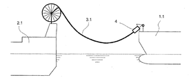
도 1은 가스 터미널과 부유식 터미널 사이로 공중식 가요성 파이프라인을 경유하는 탠덤(tandem) 유형의 액화 천연 가스(LNG) 이송을 위한 설비의 개략도이다.
도 2는 가스 터미널과 부유식 터미널 사이로 부유식 가요성 파이프라인을 경유하는 액화 천연 가스(LNG) 이송을 위한 설비의 개략도이다.
도 3은 클램핑 모듈이 폐쇄된 위치에 있는 본 발명에 따른 연결-분리 장치의 단면도이다.
도 4는 클램핑 모듈이 개방된 위치에 있는 연결-분리 장치의 단면도이다.
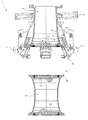
도 5는 비상 분리 후의 연결-분리 장치의 단면도이다.
도 6은 비상 분리 후의 연결-분리 장치의 사시도이다.
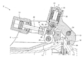
도 7, 도 8 및 도 9는 클램핑 모듈의 대칭면을 따라 도시된 클램핑 모듈의 단면도이다.
도 10은 도 9의 A-A선을 따라 도시된 단면도이다.
도 11은 도 9의 B-B선을 따라 도시된 단면도이다. Reference is made to the accompanying drawings for illustrative purposes only.
1 is a schematic diagram of a facility for the transfer of tandem type liquefied natural gas (LNG) via a aerial flexible pipeline between a gas terminal and a floating terminal.
2 is a schematic diagram of a facility for the transfer of liquefied natural gas (LNG) via a floating flexible pipeline between a gas terminal and a floating terminal.
3 is a cross-sectional view of the connection-disengagement device according to the invention with the clamping module in the closed position.
4 is a cross-sectional view of the connection-disengagement device with the clamping module in the open position.
5 is a cross-sectional view of the connection-disconnection device after emergency disconnection.
6 is a perspective view of the connection-separation device after emergency disconnection.
7, 8 and 9 are cross-sectional views of the clamping module shown along the plane of symmetry of the clamping module.
FIG. 10 is a cross-sectional view taken along line AA of FIG. 9.
FIG. 11 is a cross-sectional view taken along line BB of FIG. 9.
본 발명은 특히 도 1 및 도 2에 도시된 액화 천연 가스(LNG) 이송을 위한 설비로 통합될 수 있다.The invention can in particular be incorporated into a plant for the liquefied natural gas (LNG) transfer shown in FIGS. 1 and 2.
도 1은 개략적으로 부유식 터미널(2.1)과 가스 터미널(1.1) 사이에서 탠덤 유형(프랑스 특허 제2837190호에서 유로딤사에 의해 개시된 바와 같이)의 액화 천연 가스(LNG) 이송을 위한 설비를 개략적으로 도시하며, 이는 하중이 부과되거나 또는 부과되지 않을 수 있고, 해저에 위치한 파이프들에 의해 가스 네트워크와 연결되며, 상기 설비는 특히 하늘 높이 배치되고 부유식 터미널(2.1)에 의해 지지되는 공중식 극저온 가요성 파이프라인(3.1)을 포함하며, 연결-분리 장치(4)는 가스 터미널(1.1)과 공중식 극저온 가요성 파이프라인(3.1) 사이의 연결을 보장하는 것을 가능하게 한다.1 schematically shows a plant for the transfer of liquefied natural gas (LNG) of tandem type (as disclosed by Eurodimsa in French Patent No. 2837190) between a floating terminal 2.1 and a gas terminal 1.1. It is shown, which may or may not be charged, is connected to the gas network by pipes located at the bottom of the sea, and the installation is in particular airborne cryogenic flexible which is placed high above the sky and supported by the floating terminal 2.1. It comprises a castle pipeline 3.1, the connection-separating
도 2는 개략적으로 부유식 터미널(2.2)과 가스 터미널(1.2)사이에서 액화 천연 가스(LNG) 이송을 위한 설비를 개략적으로 도시하며, 이는 하중이 부과되거나 또는 부과되지 않을 수 있고, 해저에 위치한 파이프들에 의해 가스 네트워크와 연결되며, 상기 설비는 특히 부유식 터미널(2.2)에 의해 지지되는 부유식 극저온 가요성 파이프라인(3.2)을 포함하고, 그로 인해 연결-분리 장치(4)는 부유식 극저온 가요성 파이프라인(3.2)과 가스 터미널(1.2) 사이의 연결을 보장하는 것을 가능하게 한다.FIG. 2 schematically illustrates a facility for the transfer of liquefied natural gas (LNG) between floating terminal 2.2 and gas terminal 1.2, which may or may not be charged and located on the seabed. Connected to the gas network by pipes, the installation comprises in particular a floating cryogenic flexible pipeline 3. 2 which is supported by a floating terminal 2.2, whereby the connection-separating
도 3은 본 발명에 따른 연결-분리 장치(4)의 단면을 도시한다.3 shows a cross section of a connection-separating
이것은 두 개의 단부 부품(4.1, 4.2)으로 구성되며, 단부 부품(4.1)은 매니폴드와 연결된 가스 터미널(1) 위에 위치하지만, 다른 단부 부품(4.2)은 극저온 가요성 파이프라인(3)의 단부에 고정된다. 단부 부품(4.1, 4.2) 각각의 단부에서, 그들의 인터페이스에서, 나비형 밸브(각각은 도면부호 5.1, 5.2)는 폐쇄되어 도시된 것과 같이 위치되고, 각각 피봇 축(또는 조작 샤프트)(각각은 도면부호 6.1, 6.2)의 주위로 단부 부품의 내부에서 피봇 가능하게 설치된 디스크를 유체의 유동의 횡방향 단면의 개방 위치와 폐쇄된 위치의 사이에서 구비하고, 그리고 피보팅을 조정하기 위한 외부 장치를 구비하고, 피봇 축들은 파이프라인의 축(XX')에 수직하게 연장되고 서로 평행하게 된다. 두 나비형 밸브들(5.1, 5.2)의 면은 서로를 향하여 방향 전환된다. 제3 나비형 밸브(5.3)는 밸브의 조작 샤프트(6.3) 주위로 피봇하는 단부 부품(4.2)의 다른 단부에 위치하고, 조작 샤프트(6.1, 6.2)에 평행하며, 또한 폐쇄된 것으로 도시된 것과 같이, 제3 나비형 밸브(5.3)는 연결-분리 장치(4)의 두 단부 부품(4.1, 4.2)의 분리를 따라 극저온 가요성 파이프라인(3)의 단부에서 이중 밀봉 차단부를 제공하는 것을 가능하게 한다. 두 단부 부품(4.1, 4.2)의 접근 및 안내 시스템(도시되지 않음)은 분리 동작의 개시 및 연결 동작의 끝에서, 특히 다른 하나와의 관계에 있어서 완벽한 위치선정을 가능하게 하는 두 단부 부품(4.1, 4.2)의 동축도(coaxiality) 및 각도 배향을 보장한다.It consists of two end parts (4.1, 4.2), the end part (4.1) is located above the gas terminal (1) connected to the manifold, while the other end part (4.2) is at the end of the cryogenic flexible pipeline (3). Is fixed to. At the end of each of the
단부 부품(4.1)의 주위로 균일하게 분포된 다수의 동일한 클램핑 모듈(7)은 선 YY'를 지나는 파이프라인의 축에 방사상 면에 위치한 단부 부품의 인터페이스 레벨에서 두 단부 부품(4.1, 4.2)을 연결 또는 분리시키는 것을 가능하게 하고, 이는 부유식 터미널(2)의 파이프라인을 가스 터미널(1)의 파이프라인에 연결하기 위함이다. 각각의 클램핑 모듈(7)은 두 개의 측방향 면들 위에 홈(9)을 구비한 'U' 모양의 지지체(8)에 충분히 통합되며, 클램핑 모듈은 제1 단부 부품(4.1)에 결합된 리브(10)와 협동할 수 있도록 한다. 상기 리브(10)는 파이프라인의 축(XX')에 상대적으로 경사지도록 배치되고, 이는 클램핑 모듈(7)은(위치에 고정되지 않은 때) 리브(10)의 견부(19)와 접촉한 'U' 모양의 지지체(8)에 결합된 멈춤쇠(18) 위까지, 단부 부품(4.2)의 방향에서 리브(10)를 따라 병진운동으로 이동될 때, 이 축(XX')과 떨어져 이동하기 위함이다.A number of
ERC 유형 칼라(16)의 원추형 네크에 의해 클램핑 되는 방법과 같이, 클램핑 모듈(7)의 다른 단부는 플랜지(14)에 의해 형성되고, 단부 부품(4.1)의 본체 위로 통합된 플랜지(15)와 협동한다. 따라서 폐쇄된 때에 ERC 유형의 칼라(16)는 단부 부품(4.1) 위의 고정된 위치에서 클램핑 모듈(7)의 조립체를 유지한다. 이송 과정에서 본 클램핑 모듈에 의해 계속되는 힘은 리브(10) 및 ERC 유형 칼라(16)에 의해 단부 부품(4.1)의 레벨에서 전달된다.As with the method of clamping by the conical neck of the
이러한 클램핑 모듈들(7)은 유압 액츄에이터(11)에 의해 작용되고, 이는 단부 부품(4.1)에 대하여 다른 단부 부품(4.2)의 플랜지(12)를 체결하거나, 역으로 분리 또는 연결의 경우에 각각 해제 또는 통로를 보장한다. 체결된 상황에서, 각각의 클램핑 모듈(7)의 슈(shoe)(13)는 단부 부품(4.2)의 플랜지(12) 위에서 다른 단부 부품(4.1)을 향하여 축(XX')과 평행한 힘을 가한다. These clamping
도 3은 단부 부품(4.2)의 플랜지(12)에 대하여 폐쇄된 위치에 ERC 유형 칼라(16)의 병진 운동으로 고정된 클램핑 모듈(7)을 도시한다.3 shows the
도 4는 액츄에이터들(11)의 조립체의 로드의 복귀 이후의 연결-분리 장치(4)의 단면이며, 클램핑 모듈(7)의 조립체의 개방부를 포함한다. 파이프라인의 축(XX')에 대해 슈들(shoes)(13)의 거리는 연결에서 자유로운 통로 또는 단부 부품(4.2)의 플랜지(12)의 분리에서 해제를 허용한다. 나비형 밸브(5.1, 5.2, 5.3)는 도 4에서 폐쇄된 위치에 있다.4 is a cross section of the connection-disconnecting
통상의 분리 과정에서 단부 부품(4.2)은 가요성 파이프라인의 조작을 허용하는 연결-분리 윈치 케이블(도시되지 않음)에 의해 다른 단부 부품(4.1)과 접촉한 상태로 있게 된다. 클램핑 모듈(7)의 조립체의 완전한 개방 이후에만 연결-분리 윈치의 해제로 단부 부품(4.1)으로부터 다른 단부 부품(4.2)을 제거할 수 있게 된다.In the normal disconnection process, the end part 4.2 remains in contact with the other end part 4.1 by means of a connection-separating winch cable (not shown) which allows the manipulation of the flexible pipeline. Only after the full opening of the assembly of the
도 5는 비상 분리 이후의 연결-분리 장치(4)의 단면이다. ERC 유형 칼라(16)의 개방(나비형 밸브(5.1, 5.2, 5.3)의 폐쇄가 선행됨)은 슈(13)를 이용하여 클램핑 모듈(7) 전체의 이동을 포함하는 단부 부품(4.2)의 플랜지(12)의 추력의 영향 아래 경사진 리브(10)를 따라 활주할 수 있는 클램핑 모듈(7)의 해제를 가능하게 한다. 이러한 플랜지(12)의 추력은 수평방향에 대하여 연결-분리 장치(4)의 현저한 경사에 의해 가능하게 되고, 추가적으로 자체 하중으로 강하하는 극저온 가요성 파이프라인(3), 부유식 가요성 파이프라인을 통해 이송하는 동안 수직한 위치가 된다. 따라서, 단부 부품(4.2)은 유도 시스템(도시되지 않음)을 이용하여 동축 방향 방식으로 다른 단부 부품(4.1)으로부터 스스로 분리한다. 그러므로 단부 부품(4.2)의 플랜지(12)는 플랜지(12)의 외부 직경보다 축(XX')과의 관계에서 가장 낮은 지점의 레벨의 슈(13)의 반경이 커질 때까지 각각의 클램핑 모듈(7)의 슈(13)와 접촉하며, 이는 슈(13)의 분리를 용이하게 하는 모따기(20)가 구비된다. 제1 단부 부품(4.1)의 본체의 견부(19)와 접촉하게 되는 멈춤쇠(18)는 플랜지(12)의 분리를 따라 리브(10)에서 그 홈들(9)을 통해 병진 운동하는 클램핑 모듈(7)을 정지시킨다.5 is a cross section of the connection-separating
도 6은 비상 분리 후의 연결-분리 장치(4)의 사시도이다. 두 개의 단부 부품(4.1, 4.2)을 유도하기 위한 시스템 및 나비형 밸브(5.1, 5.2, 5.3)를 구동시키기 위한 장치는 도시되지 않았다.6 is a perspective view of the connection-disconnecting
그러므로, 폐쇄된 위치로 클램핑 모듈(7)이 활주함에 의해 ERC 유형 칼라(16)의 개방은 연결-분리 장치(4)의 신속한 분리를 가능하게 한다. 그러나, 비상 분리의 경우에 추가적인 고정을 제공하기 위하여, ERC 유형 칼라(16)의 개방에 더하여, 클램핑 모듈(7)의 개방(도 4에 도시됨)이 작동되고, 두 장치 모두의 가능한 고장을 수용한다.Therefore, the opening of the
최소한 세 개의, 클램핑 모듈(7)은 나비형 밸브들(5.1, 5.2)의 네크(17.1, 17.2)와 간섭하지 않는 방법으로 단부 부품(4.1) 주위로 균일하게 분포한다. At least three clamping
'U' 모양의 지지체(8)에 대한 저널(41)의 주위로 피봇 연결된 액츄에이터(11)는 피스톤(22)의 단부에 고정된 커버 부품(24)을 구비한다. 커버 부품(24)의 단부에 위치한 축(25)은 한편으로는 두 개의 연결 로드들(28)과 함께, 축(26) 주위의 'U' 모양의 지지체(8)와 다른 단부에서 피봇 연결로 피봇 연결을 형성하는 것을 가능하게 하고, 다른 한편으로는, 중앙 연결 로드(29)와 함께, 축(27) 주위의 플런저(30)와 다른 단부에서 피봇 연결을 가능하게 한다. 조오(13)의 내부로 나사 결합되고 커버(31)의 보어(33) 뿐만 아니라 조오(13)의 보어(37)에서도 유도되는 상기 플런저(30)는 견부(43)에 의해 도면부호 u를 향하여, 견부(42)에 의해 도면부호 u'를 향하여 제한되는, 축(uu')을 따라 병진 운동을 하게 된다. 스프링(32)의 하우징은 플런저(30)의 병진운동이 스프링을 압축 또는 압축하지 않는 것을 가능하게 하는 방식으로 커버(31)의 내부에 위치하게 된다. 하나의 단부에서는 축(34) 주위의 조오(13)와 피봇 연결되고, 다른 하나의 단부에서는 축(26) 주위로 'U' 모양 안의 지지체(8)와 피봇 연결된 두 개의 측방향 로드(35)는 그들 사이에서 고정된 멈춤쇠(38)를 구비하고, 멈춤쇠(38)는 상부면(23)에서 조오(13)와 접촉하고 측방향 면(21)에서 커버 부품(24)과 접촉할 수 있다. 조오(13)는 단부 부품(4.2)의 플랜지(12)와 접촉할 수 있는 두개의 패드(36)를 조오의 단부에서 구비한다. 축(27)은 각각의 단부에서 두 개의 롤러가 구비되며, 소형 롤러(44)는 'U' 모양의 지지체(8)의 커브(39, 40)와 접촉하고, 대형 롤러(45)는 측면의 연결 로드들(35)의 상부면에 접촉할 수 있다. 'U' 모양의 지지체(8)의 상기 커브(39, 40)는 도 3 및 도 4에서 볼 수 있다.The
도 7, 도 8 및 도 9는 대칭 면을 따른 클램핑 모듈(7)의 단면도이다. 7, 8 and 9 are cross-sectional views of the
도 7은 클램핑 모듈(7)의 개방 위치에 대응된다. 이 위치는 연결-분리 장치(4)의 유도 시스템(도시되지 않음)을 이용하여 동축 방향 방식으로, 단부 부품(4.1)의 관계에서 다른 단부 부품(4.2)의 플랜지(12)의 제거 또는 접근을 가능하게 하는 연결-분리 장치(4)의 구동상의 연결 또는 분리를 가능하게 한다.7 corresponds to the open position of the
클램핑 모듈(7)의 폐쇄는 액츄에이터(11)의 피스톤(22)의 방출에 의해 시작되며, 이는 커버 부품(24)을 이용하여 축(25)의 이동을 포함하고, 그로 인하여 다른 축들(26, 27)의 사이로 축이 이동하기 쉽게 되고, 측방향 연결 로드(35)의 상부 부분과 단부에 고정된 대형 롤러(45) 사이의 접촉에 의해 허용된 축(27)을 높은 위치에 고정함으로써 이루어지고, 이는 또한 캡(31)과 조오(13)의 내부의 플런저(30)의 상부를 향한 이동을 야기시키며, 스프링(32)의 하우징의 압축을 포함한다. 'U' 모양의 지지체(8)의 소형 롤러(44)가 접촉하게 되는 커브(39, 40)의 모양은 축(27)의 적절한 위치 선정을 가능하게 한다. 측면(21)의 레벨에서 'U' 모양의 지지체(8)와 멈춤쇠(38)가 접촉할 때 축(34)의 위치가 설정된다. 따라서 추가적인 피스톤(11)의 이동은 축(27)의 리프팅을 야기시키고, 소형 롤러(44)는 'U' 모양의 지지체(8)의 슬로프(40)의 레벨에 위치하게 되며, 단부 부품(4.1)에 대해 다른 단부 부품(4.2)의 플랜지(12)를 체결하고 패드들(36)과 접촉할 때까지 축(34) 주위로 조오(13)의 시계방향 회전을 포함한다. 도 8은 이에 따라 폐쇄된 위치의 클램핑 모듈(7)을 도시한다.The closing of the
액츄에이터(11)의 피스톤(22)의 방출을 추적하는 것은 첫 단계로 축(25, 26, 27)을 정렬하는 것을 포함하고, 그에 따라 최대로 압축된 스프링(32)의 하우징은, 도 9에서 도시된 바와 같이, 멈춤쇠(38)의 측방향 면(46)에 구비한 커버 부품(24)이 접촉할 때까지, 축들(26, 27)을 지나는 평면의 우측으로 축(25)을 움직이게 한다. 따라서, 스프링(32)의 하우징은 이전 위치와 비교하여 미세하게 압축이 풀리게 되지만, 선 uu'에서 도면부호 u' 방향으로 작용하는 주된 힘은 버팀대에 의해 기계적으로 운동을 고정하는 것이 가능하며, 조오(13)에 의해 흡수되는 힘에 관계없이 축(25)은 더 이상 액츄에이터(11)의 작동 없이 축들(26, 27)을 지나는 평면의 좌측에 위치할 수 없게 된다. 따라서 LNG를 이송하는 동안, 안전장치로서, 액츄에이터(11)에 유압을 공급하는 것에 결함이 발생할지라도, 클램핑 모듈(7)의 폐쇄 및 고정된 위치가 기계적으로 보장된다. Tracking the release of the
따라서 클램핑 모듈의 재개방은 축들(26, 27)을 지나는 평면의 좌측으로 축(25)의 이동에 의해 시스템의 운동의 지지대 부재를 야기하는 액츄에이터(11)의 피스톤(22)의 귀환에 의해 시작되며, 'U' 모양의 지지대(8)의 커브(40)에 대해서 단부에 고정된 소형 롤러(44)의 접촉에 의해 제자리의 축(27)을 고정함으로써 가능하게 된다. 피스톤(22)의 복귀를 추적하는 것은 특히 중앙 연결 로드(29)를 이용하여, 'U' 모양의 지지체(8)의 커브(39, 40)를 따라 소형 롤러(44)의 이동 및 축(27)의 이동을 포함한다. 도 7에 도시된 바와 같이, 이는 축(34) 주위로 조오(13)의 반시계 방향 회전을 가능하게 하고 그리고 나서 축(26) 주위의 측방향 연결 로드(35)가 회전할 수 있게 되며, 클램핑 모듈(7)의 개방을 가능하게 하고, 피스톤(22)이 완전히 복귀한 때 완료된다. 단부 부품(4.1) 위의 조오(13)의 위치에 따른 중력의 영향은, 한편으로는, 위로 기울어지는 것을 막는 'U' 모양의 지지체(8)의 커브(39)와 소형 롤러(44)의 접촉에 의해 그리고 다른 한편으로는, 아래로 기울어지는 것을 막고 그로인해 개방 위치에서 고정시키는 멈춤쇠(38)에 의해 조정된다.The reopening of the clamping module thus starts by the return of the
도 10에 도시된 바와 같이, 이는 도 9의 선 A-A에 따른 단면도이며, 각각의 클램핑 모듈(7)은 지지체가 단부 부품(4.1)의 본체에 결합된 두 개의 리브(10)와 협동하도록 두 측방향 면 위로 홈(9)과 같이 구비되는 'U' 모양의 지지체(8)로 완전히 통합되고, 단부 부품(4.1)과의 관계에서 각각의 클램핑 모듈(7)이 활주되도록 한다.As shown in FIG. 10, this is a cross sectional view along the line AA of FIG. 9, with each clamping
도 11은 도 9의 B-B선을 따르는 단면이며, 특히 롤러들(44, 45) 및 그와 접촉하게 되는 부품들을 시각화할 수 있도록 한다.FIG. 11 is a cross section along line B-B of FIG. 9, which makes it possible in particular to visualize the
4 : 연결-분리 장치
4.1 : 제1 단부 부품
4.2 : 제2 단부 부품
5.1 : 제1 나비형 밸브
5.2 : 제2 나비형 밸브
8 : 지지체
9 : 홈
10 : 리브
11 : 액츄에이터
12 : 플랜지
13 : 조오
14 : 플랜지
16 : 클램핑 칼라
18 : 멈춤쇠
19 : 견부
39 : 커브4: connection-disconnector
4.1: First end part
4.2: second end part
5.1: first butterfly valve
5.2: second butterfly valve
8: support
9: Home
10: rib
11: Actuator
12: Flange
13: jao
14: flange
16: clamping collar
18: detent
19: shoulder
39: curve
Claims (5)
가요성 파이프라인에 연결된 제1 단부 부품(4.1) 및 제2 단부 부품(4.2) 그리고 다수의 클램핑 모듈(7)을 포함하고,
각각의 모듈은 지지체에 의해 상기 제1 단부 부품(4.1)에 설치되고, 작동 모드에서 연결의 개방 시에는 서로 멀어지도록 이동하고 연결의 폐쇄시에는 상기 제2 단부 부품(4.2)의 플랜지(12) 뒤에 고정되도록 회전 구성요소와의 제1 이동을 따라 배치되고,
비상 모드에서는, 각각의 모듈(7)은 보유 장치(16)에 의해 고정되는, 단부 부품들(4.1, 4.2)을 서로에 대해 고정할 수 있는 보유 위치로부터 이것을 더 이상 수행하지 않는 해제 위치까지 제2 이동을 따라 이동 가능하게 장착되며,
상기 제2 이동은 상기 모듈(7)과 상기 제2 단부 부품(4.2)의 방향을 따라 점점 더 상기 단부 부품들(4.1, 4.2)의 축으로부터 그들을 제거하는 지지체의 일괄적인 병진 운동인 것을 특징으로 하는 연결-분리 장치.Connection-disconnection device,
A first end part (4.1) and a second end part (4.2) and a plurality of clamping modules (7) connected to the flexible pipeline,
Each module is installed on the first end part 4.1 by means of a support, which moves away from each other when the connection is opened in the operating mode and the flange 12 of the second end part 4.2 when the connection is closed. Disposed along a first movement with the rotating component to be secured to the back,
In the emergency mode, each module 7 is moved from a holding position, which can hold the end parts 4. 1, 4.2, which are fixed by the holding device 16 to each other, to a release position which no longer does this. 2 is equipped to move along the movement,
Said second movement is a collective translational movement of the support which removes them more and more from the axis of the end parts 4. 1, 4.2 along the direction of the module 7 and the second end part 4. 2. Connection-disconnection device.
상기 제2 이동은 상기 제1 단부 부품(4.1)의 축의 관계에서 경사지고 상기 제1 단부 부품(4.1)에 결합된 두 개의 리브(10)와 상기 모듈(7)의 두 측방향 면들 위로 난 홈(9)의 협동작용으로 얻어지며,
상기 제2 이동은 가요성 파이프라인(3.1, 3.2)의 본체 무게에 의해 발생하고,
상기 제2 이동은 상기 연결-분리 장치(4)의 축의 횡방향에 대하여 급격한 경사에 의해 가능하고,
상기 제1 단부 부품(4.1)은 상기 제2 단부 부품(4.2)보다 높이 위치하며 두 개의 상기 단부 부품들은 동축 방향 방식으로 다른 하나와 분리되는 것을 특징으로 하는 연결-분리 장치.3. The method according to claim 1 or 2,
The second movement is inclined in relation to the axis of the first end part 4.1 and is grooved over the two ribs 10 and the two lateral faces of the module 7 coupled to the first end part 4.1. Obtained by cooperation of (9),
The second movement is caused by the body weight of the flexible pipelines 3.1 and 3.2,
The second movement is made possible by a sharp inclination with respect to the transverse direction of the axis of the connection-separating device 4,
The first end part (4.1) is located higher than the second end part (4.2) and the two end parts are separated from one another in a coaxial direction.
상기 제2 단부 부품(4.2)을 향하여 선회되는 상기 제1 단부 부품(4.1)의 단부에 제1 나비형 밸브(5.1)가 설치되고,
상기 제1 단부 부품(4.1)을 향하여 선회되는 상기 제2 단부 부품(4.2)의 단부에 제2 나비형 밸브(5.2)가 설치되고,
상기 제1 단부 부품(4.1)으로부터 이격되어 상기 제2 단부 부품(4.2)의 단부에 제3 나비형 밸브(5.3)가 설치된 것을 특징으로 하는 연결-분리 장치.4. The method according to any one of claims 1 to 3,
A first butterfly valve (5.1) is provided at the end of the first end component (4.1) which is pivoted towards the second end component (4.2),
A second butterfly valve 5.2 is installed at the end of the second end part 4.2 which is pivoted towards the first end part 4.1.
A connecting-disconnecting device, characterized in that a third butterfly valve (5.3) is provided at the end of the second end part (4.2) away from the first end part (4.1).
Either one is in a facility for conveying fluid through a floating flexible pipeline (3.1) or a floating flexible pipeline (3.2) between two vessels (1, 2), which are nautical vessels (1). Method of use of the connection-separating device (4) according to any of the preceding claims.
Applications Claiming Priority (3)
| Application Number | Priority Date | Filing Date | Title |
|---|---|---|---|
| FR1004201 | 2010-10-26 | ||
| FR1004201A FR2966553B1 (en) | 2010-10-26 | 2010-10-26 | CONNECTING DEVICE WITH FREEZING CLAMP MODULES. |
| PCT/FR2011/000572 WO2012056123A1 (en) | 2010-10-26 | 2011-10-25 | Connection device with releasable clamping modules |
Publications (2)
| Publication Number | Publication Date |
|---|---|
| KR20130143574A true KR20130143574A (en) | 2013-12-31 |
| KR101787158B1 KR101787158B1 (en) | 2017-10-18 |
Family
ID=44356292
Family Applications (1)
| Application Number | Title | Priority Date | Filing Date |
|---|---|---|---|
| KR1020137010595A KR101787158B1 (en) | 2010-10-26 | 2011-10-25 | Connection device with releasable clamping modules |
Country Status (8)
| Country | Link |
|---|---|
| EP (1) | EP2632790B1 (en) |
| JP (1) | JP5912123B2 (en) |
| KR (1) | KR101787158B1 (en) |
| CN (1) | CN103249641B (en) |
| BR (1) | BR112013010137A2 (en) |
| DK (1) | DK2632790T3 (en) |
| FR (1) | FR2966553B1 (en) |
| WO (1) | WO2012056123A1 (en) |
Families Citing this family (11)
| Publication number | Priority date | Publication date | Assignee | Title |
|---|---|---|---|---|
| NO2473769T3 (en) * | 2009-09-03 | 2018-05-26 | ||
| CN102865428A (en) * | 2012-09-27 | 2013-01-09 | 李宏 | Ultralow temperature vacuum insulation quick connector and production method thereof |
| CN105658570B (en) | 2013-10-18 | 2017-11-17 | 国际壳牌研究有限公司 | For conveying the loading assembly of forced air and using the switching system in loading assembly |
| CN104251367B (en) * | 2014-08-18 | 2016-03-30 | 中国科学院高能物理研究所 | A kind of very low temperature flow transfer line vacuum separation device |
| MY186902A (en) * | 2014-11-19 | 2021-08-26 | Shell Int Research | Loading assembly for conveying a pressurized gas stream and a switching system for use in such a loading assembly |
| CN104405988B (en) * | 2014-11-30 | 2016-03-02 | 连云港远洋流体装卸设备有限公司 | Synchronous mode Quick Connect Kit |
| EP3048403B1 (en) * | 2015-01-20 | 2017-11-29 | LOI Thermprocess GmbH | Support roller exchange device and method |
| EP3048404B1 (en) | 2015-01-20 | 2018-04-11 | LOI Thermprocess GmbH | Support roller exchange device and method for exchanging support rollers |
| NO341918B1 (en) * | 2016-05-04 | 2018-02-19 | Cefront Tech As | Offshore loading hose coupling |
| TWI614440B (en) * | 2017-06-02 | 2018-02-11 | Li yue lin | Anti-loose buckle and pipe joint applying the same |
| CN116533895B (en) * | 2023-07-05 | 2023-09-15 | 荣成康派斯新能源车辆股份有限公司 | Caravan sewage draining device with vibration function and use method thereof |
Family Cites Families (22)
| Publication number | Priority date | Publication date | Assignee | Title |
|---|---|---|---|---|
| US2199588A (en) * | 1936-12-10 | 1940-05-07 | Flight Refueling Ltd | Apparatus for refueling aircraft in the air |
| FR1001500A (en) | 1946-05-22 | 1952-02-25 | Intermediaire De Credit Et De | Thermal machine applying hyperdialysis of helium below the lambda point |
| FR1001499A (en) | 1946-05-22 | 1952-02-25 | Advanced semi-automatic lighter | |
| US2825583A (en) * | 1953-07-20 | 1958-03-04 | Shell Dev | Pipe coupler with shut-off valve |
| US3445127A (en) * | 1967-05-26 | 1969-05-20 | Hydrasearch Co Inc | Universal flange connector |
| GB1198153A (en) * | 1967-06-10 | 1970-07-08 | Giorgio Bormioli | Pipe-Connecting Device |
| US3586350A (en) * | 1969-05-23 | 1971-06-22 | Youngstown Sheet And Tube Co | Coupler |
| US3642307A (en) * | 1969-09-26 | 1972-02-15 | Abner A Brickhouse | Quick-release coupling |
| GB1604826A (en) * | 1978-05-31 | 1981-12-16 | Ashlow Steel & Eng Co | Pipe couplings |
| FR2572786B1 (en) * | 1984-11-07 | 1988-01-15 | Amri | EMERGENCY DISCONNECTOR FOR LOADING OR UNLOADING ARM OF A FLUID TRANSPORT VEHICLE |
| IT1201176B (en) * | 1987-01-21 | 1989-01-27 | Giorgio Bormioli | QUICK COUPLING DEVICE FOR CONDUCTURES |
| JPH0617864Y2 (en) * | 1988-11-09 | 1994-05-11 | 株式会社大林組 | Connecting device for pumping mud pipe for ground excavator |
| JPH0712796Y2 (en) * | 1991-11-15 | 1995-03-29 | 株式会社新潟鉄工所 | Emergency disconnection device for fluid handling equipment |
| FR2827033B1 (en) | 2001-07-03 | 2004-08-20 | Eurodim Sa | ARRANGEMENT FOR CONNECTING AND DISCONNECTING TWO PIPE LINES OF A FLUID TRANSFER SYSTEM |
| FR2834043B1 (en) | 2001-12-21 | 2004-10-15 | Fmc Technologies Sa | IMPROVED TIGHTENING ASSEMBLY AND HYDRAULIC COUPLER COMPRISING SAME |
| FR2837190B1 (en) | 2002-03-15 | 2004-10-08 | Eurodim Sa | SYSTEM FOR TRANSFERRING A FLUID PRODUCT, ESPECIALLY LIQUEFIED NATURAL GAS, BETWEEN A FLUID TRANSPORT VESSEL AND A STORAGE STATION |
| FR2903653B1 (en) * | 2006-07-13 | 2009-04-10 | Eurodim Sa | SYSTEM FOR TRANSFERRING A FLUID SUCH AS LIQUEFIED NATURAL GAS BETWEEN A SHIP, SUCH AS A SHUTTLE METHANIER AND A FLOATING OR FIXED UNIT. |
| FR2903753B1 (en) * | 2006-07-13 | 2012-01-20 | Eurodim Sa | DEVICE FOR CONNECTING THE END OF A DEFORMABLE CONDUIT FOR DELIVERING A FLUID TO A FIXED PIPING SYSTEM SUCH AS THE MANIFOLD OF A SHIP. |
| JP5448541B2 (en) * | 2008-11-25 | 2014-03-19 | 株式会社ハタノ製作所 | Pipe connection equipment |
| NO2473769T3 (en) * | 2009-09-03 | 2018-05-26 | ||
| FR2965559B1 (en) * | 2010-10-05 | 2012-09-21 | Ksb Sas | FLUID TRANSFER INSTALLATION |
| JP6017864B2 (en) | 2012-07-04 | 2016-11-02 | 株式会社シマノ | Cylindrical member for fishing rod and its manufacturing method |
-
2010
- 2010-10-26 FR FR1004201A patent/FR2966553B1/en active Active
-
2011
- 2011-10-25 BR BR112013010137A patent/BR112013010137A2/en active Search and Examination
- 2011-10-25 KR KR1020137010595A patent/KR101787158B1/en active IP Right Grant
- 2011-10-25 WO PCT/FR2011/000572 patent/WO2012056123A1/en active Application Filing
- 2011-10-25 JP JP2013535478A patent/JP5912123B2/en active Active
- 2011-10-25 CN CN201180050999.5A patent/CN103249641B/en active Active
- 2011-10-25 EP EP11785043.8A patent/EP2632790B1/en active Active
- 2011-10-25 DK DK11785043.8T patent/DK2632790T3/en active
Also Published As
| Publication number | Publication date |
|---|---|
| KR101787158B1 (en) | 2017-10-18 |
| CN103249641A (en) | 2013-08-14 |
| CN103249641B (en) | 2015-11-25 |
| FR2966553A1 (en) | 2012-04-27 |
| FR2966553B1 (en) | 2015-01-02 |
| EP2632790B1 (en) | 2014-12-10 |
| JP2013545943A (en) | 2013-12-26 |
| DK2632790T3 (en) | 2015-02-16 |
| WO2012056123A1 (en) | 2012-05-03 |
| EP2632790A1 (en) | 2013-09-04 |
| JP5912123B2 (en) | 2016-04-27 |
| BR112013010137A2 (en) | 2016-09-06 |
Similar Documents
| Publication | Publication Date | Title |
|---|---|---|
| KR101787158B1 (en) | Connection device with releasable clamping modules | |
| RU2551826C2 (en) | Fluid transfer line with locking modules | |
| US9534716B2 (en) | Structural connector diverting loads away from the cool connector | |
| RU2527819C2 (en) | Connecting device | |
| AU2008333268B2 (en) | Connector with an integrated quick/connect disconnect and emergency release system | |
| US10132440B2 (en) | Launch system for a pressurized pipeline | |
| DK2691682T3 (en) | Autonomous, electric rørforingsværktøj | |
| KR20160117504A (en) | Connection device for connecting two fluid circuits | |
| US4142740A (en) | Quick disconnect coupler | |
| DK2625093T3 (en) | Device for controlling the valves in a connection / separation device | |
| CN106061832B (en) | System for liquefied natural gas to be delivered to a facility from a ship | |
| EP3234432B1 (en) | Coupling assembly for conveying pressurized gas with emergency release system | |
| JPH0646880Y2 (en) | Emergency release device for fluid handling equipment | |
| CN104285090A (en) | Coupling for connecting fluid-conducting lines |
Legal Events
| Date | Code | Title | Description |
|---|---|---|---|
| A201 | Request for examination | ||
| E902 | Notification of reason for refusal | ||
| E701 | Decision to grant or registration of patent right | ||
| GRNT | Written decision to grant |