KR20130143105A - Method for deciding resource-specific transmission mode in wireless communication system and apparatus for same - Google Patents
Method for deciding resource-specific transmission mode in wireless communication system and apparatus for same Download PDFInfo
- Publication number
- KR20130143105A KR20130143105A KR1020137019735A KR20137019735A KR20130143105A KR 20130143105 A KR20130143105 A KR 20130143105A KR 1020137019735 A KR1020137019735 A KR 1020137019735A KR 20137019735 A KR20137019735 A KR 20137019735A KR 20130143105 A KR20130143105 A KR 20130143105A
- Authority
- KR
- South Korea
- Prior art keywords
- base station
- subframe
- transmission mode
- signal
- transmission
- Prior art date
Links
Images


Classifications
-
- H—ELECTRICITY
- H04—ELECTRIC COMMUNICATION TECHNIQUE
- H04L—TRANSMISSION OF DIGITAL INFORMATION, e.g. TELEGRAPHIC COMMUNICATION
- H04L5/00—Arrangements affording multiple use of the transmission path
- H04L5/0091—Signaling for the administration of the divided path
-
- H—ELECTRICITY
- H04—ELECTRIC COMMUNICATION TECHNIQUE
- H04B—TRANSMISSION
- H04B7/00—Radio transmission systems, i.e. using radiation field
- H04B7/02—Diversity systems; Multi-antenna system, i.e. transmission or reception using multiple antennas
- H04B7/04—Diversity systems; Multi-antenna system, i.e. transmission or reception using multiple antennas using two or more spaced independent antennas
- H04B7/06—Diversity systems; Multi-antenna system, i.e. transmission or reception using multiple antennas using two or more spaced independent antennas at the transmitting station
- H04B7/0613—Diversity systems; Multi-antenna system, i.e. transmission or reception using multiple antennas using two or more spaced independent antennas at the transmitting station using simultaneous transmission
- H04B7/0615—Diversity systems; Multi-antenna system, i.e. transmission or reception using multiple antennas using two or more spaced independent antennas at the transmitting station using simultaneous transmission of weighted versions of same signal
- H04B7/0619—Diversity systems; Multi-antenna system, i.e. transmission or reception using multiple antennas using two or more spaced independent antennas at the transmitting station using simultaneous transmission of weighted versions of same signal using feedback from receiving side
- H04B7/0621—Feedback content
- H04B7/0632—Channel quality parameters, e.g. channel quality indicator [CQI]
-
- H—ELECTRICITY
- H04—ELECTRIC COMMUNICATION TECHNIQUE
- H04W—WIRELESS COMMUNICATION NETWORKS
- H04W72/00—Local resource management
- H04W72/04—Wireless resource allocation
-
- H—ELECTRICITY
- H04—ELECTRIC COMMUNICATION TECHNIQUE
- H04B—TRANSMISSION
- H04B7/00—Radio transmission systems, i.e. using radiation field
- H04B7/02—Diversity systems; Multi-antenna system, i.e. transmission or reception using multiple antennas
- H04B7/022—Site diversity; Macro-diversity
- H04B7/024—Co-operative use of antennas of several sites, e.g. in co-ordinated multipoint or co-operative multiple-input multiple-output [MIMO] systems
-
- H—ELECTRICITY
- H04—ELECTRIC COMMUNICATION TECHNIQUE
- H04B—TRANSMISSION
- H04B7/00—Radio transmission systems, i.e. using radiation field
- H04B7/02—Diversity systems; Multi-antenna system, i.e. transmission or reception using multiple antennas
- H04B7/04—Diversity systems; Multi-antenna system, i.e. transmission or reception using multiple antennas using two or more spaced independent antennas
- H04B7/06—Diversity systems; Multi-antenna system, i.e. transmission or reception using multiple antennas using two or more spaced independent antennas at the transmitting station
- H04B7/0613—Diversity systems; Multi-antenna system, i.e. transmission or reception using multiple antennas using two or more spaced independent antennas at the transmitting station using simultaneous transmission
- H04B7/0615—Diversity systems; Multi-antenna system, i.e. transmission or reception using multiple antennas using two or more spaced independent antennas at the transmitting station using simultaneous transmission of weighted versions of same signal
- H04B7/0619—Diversity systems; Multi-antenna system, i.e. transmission or reception using multiple antennas using two or more spaced independent antennas at the transmitting station using simultaneous transmission of weighted versions of same signal using feedback from receiving side
- H04B7/0636—Feedback format
- H04B7/0639—Using selective indices, e.g. of a codebook, e.g. pre-distortion matrix index [PMI] or for beam selection
-
- H—ELECTRICITY
- H04—ELECTRIC COMMUNICATION TECHNIQUE
- H04B—TRANSMISSION
- H04B7/00—Radio transmission systems, i.e. using radiation field
- H04B7/02—Diversity systems; Multi-antenna system, i.e. transmission or reception using multiple antennas
- H04B7/10—Polarisation diversity; Directional diversity
-
- H—ELECTRICITY
- H04—ELECTRIC COMMUNICATION TECHNIQUE
- H04J—MULTIPLEX COMMUNICATION
- H04J11/00—Orthogonal multiplex systems, e.g. using WALSH codes
- H04J11/0023—Interference mitigation or co-ordination
- H04J11/005—Interference mitigation or co-ordination of intercell interference
- H04J11/0053—Interference mitigation or co-ordination of intercell interference using co-ordinated multipoint transmission/reception
-
- H—ELECTRICITY
- H04—ELECTRIC COMMUNICATION TECHNIQUE
- H04W—WIRELESS COMMUNICATION NETWORKS
- H04W72/00—Local resource management
- H04W72/04—Wireless resource allocation
- H04W72/044—Wireless resource allocation based on the type of the allocated resource
- H04W72/0446—Resources in time domain, e.g. slots or frames
-
- H—ELECTRICITY
- H04—ELECTRIC COMMUNICATION TECHNIQUE
- H04W—WIRELESS COMMUNICATION NETWORKS
- H04W72/00—Local resource management
- H04W72/50—Allocation or scheduling criteria for wireless resources
- H04W72/54—Allocation or scheduling criteria for wireless resources based on quality criteria
- H04W72/542—Allocation or scheduling criteria for wireless resources based on quality criteria using measured or perceived quality
Abstract
Description
본 발명은 무선 통신 시스템에 관한 것으로서, 보다 상세하게는, 무선 통신 시스템에서 자원 특정 전송 모드 결정 방법 및 이를 위한 장치에 관한 것이다.The present invention relates to a wireless communication system, and more particularly, to a method and apparatus for determining a resource specific transmission mode in a wireless communication system.
본 발명이 적용될 수 있는 무선 통신 시스템의 일례로서 3GPP LTE (3rd Generation Partnership Project Long Term Evolution; 이하 "LTE"라 함) 통신 시스템에 대해 개략적으로 설명한다.As an example of a wireless communication system to which the present invention can be applied, a 3GPP LTE (Third Generation Partnership Project) Long Term Evolution (LTE) communication system will be schematically described.
도 1은 무선 통신 시스템의 일례로서 E-UMTS 망구조를 개략적으로 도시한 도면이다. E-UMTS(Evolved Universal Mobile Telecommunications System) 시스템은 기존 UMTS(Universal Mobile Telecommunications System)에서 진화한 시스템으로서, 현재 3GPP에서 기초적인 표준화 작업을 진행하고 있다. 일반적으로 E-UMTS는 LTE(Long Term Evolution) 시스템이라고 할 수도 있다. UMTS 및 E-UMTS의 기술 규격(technical specification)의 상세한 내용은 각각 "3rd Generation Partnership Project; Technical Specification Group Radio Access Network"의 Release 7과 Release 8을 참조할 수 있다.1 is a diagram schematically showing an E-UMTS network structure as an example of a wireless communication system. The Evolved Universal Mobile Telecommunications System (E-UMTS) system evolved from the existing Universal Mobile Telecommunications System (UMTS), and is currently undergoing basic standardization work in 3GPP. In general, E-UMTS may be referred to as an LTE (Long Term Evolution) system. For details of the technical specifications of UMTS and E-UMTS, refer to
도 1을 참조하면, E-UMTS는 단말(User Equipment; UE)과 기지국(eNode B; eNB, 네트워크(E-UTRAN)의 종단에 위치하여 외부 네트워크와 연결되는 접속 게이트웨이(Access Gateway; AG)를 포함한다. 기지국은 브로드캐스트 서비스, 멀티캐스트 서비스 및/또는 유니캐스트 서비스를 위해 다중 데이터 스트림을 동시에 전송할 수 있다.1, the E-UMTS includes an Access Gateway (AG) located at the end of a User Equipment (UE) and a base station (eNode B, eNB, E-UTRAN) The base station may simultaneously transmit multiple data streams for the broadcast service, the multicast service, and / or the unicast service.
한 기지국에는 하나 이상의 셀이 존재한다. 셀은 1.25, 2.5, 5, 10, 15, 20Mhz 등의 대역폭 중 하나로 설정돼 여러 단말에게 하향 또는 상향 전송 서비스를 제공한다. 서로 다른 셀은 서로 다른 대역폭을 제공하도록 설정될 수 있다. 기지국은 다수의 단말에 대한 데이터 송수신을 제어한다. 하향링크(Downlink; DL) 데이터가 전송될 시간/주파수 영역, 부호화, 데이터 크기, HARQ(Hybrid Automatic Repeat and reQuest) 관련 정보 등을 알려준다. 또한, 상향링크(Uplink; UL) 데이터에 대해 기지국은 상향링크 스케줄링 정보를 해당 단말에게 전송하여 해당 단말이 사용할 수 있는 시간/주파수 영역, 부호화, 데이터 크기, HARQ 관련 정보 등을 알려준다. 기지국간에는 사용자 트래픽 또는 제어 트래픽 전송을 위한 인터페이스가 사용될 수 있다. 핵심망(Core Network; CN)은 AG와 단말의 사용자 등록 등을 위한 네트워크 노드 등으로 구성될 수 있다. AG는 복수의 셀들로 구성되는 TA(Tracking Area) 단위로 단말의 이동성을 관리한다.One or more cells exist in one base station. The cell is set to one of the bandwidths of 1.25, 2.5, 5, 10, 15, 20Mhz and the like to provide downlink or uplink transmission service to a plurality of UEs. Different cells may be configured to provide different bandwidths. The base station controls data transmission and reception for a plurality of terminals. Downlink (DL) data informs the time / frequency domain to be transmitted, encoding, data size, and HARQ (Hybrid Automatic Repeat and reQuest) related information. In addition, the base station transmits uplink scheduling information to uplink (UL) data, and notifies the UE of time / frequency domain, coding, data size, and HARQ related information that the UE can use. An interface for transmitting user traffic or control traffic may be used between base stations. The Core Network (CN) can be composed of an AG and a network node for user registration of the UE. The AG manages the mobility of the UE in units of a tracking area (TA) composed of a plurality of cells.
무선 통신 기술은 WCDMA를 기반으로 LTE까지 개발되어 왔지만, 사용자와 사업자의 요구와 기대는 지속적으로 증가하고 있다. 또한, 다른 무선 접속 기술이 계속 개발되고 있으므로 향후 경쟁력을 가지기 위해서는 새로운 기술 진화가 요구된다. 비트당 비용 감소, 서비스 가용성 증대, 융통성 있는 주파수 밴드의 사용, 단순구조와 개방형 인터페이스, 단말의 적절한 파워 소모 등이 요구된다.Wireless communication technologies have been developed to LTE based on WCDMA, but the demands and expectations of users and operators are continuously increasing. In addition, as other radio access technologies continue to be developed, new technological evolution is required to be competitive in the future. Reduced cost per bit, increased service availability, the use of flexible frequency bands, simple structure and open interface, and adequate power consumption of the terminal are required.
상술한 바와 같은 논의를 바탕으로 이하에서는 무선 통신 시스템에서 자원 특정 전송 모드 결정 방법 및 이를 위한 장치를 제안하고자 한다.Based on the above discussion, a method and apparatus for determining a resource specific transmission mode in a wireless communication system will now be proposed.
본 발명의 일 양상인One aspect of the present invention
본 발명의 실시예에 따르면 단말은 자원 특정 측정 기법을 효과적으로 수행할 수 있다.According to an embodiment of the present invention, the UE can effectively perform a resource specific measurement technique.
본 발명에서 얻을 수 있는 효과는 이상에서 언급한 효과들로 제한되지 않으며, 언급하지 않은 또 다른 효과들은 아래의 기재로부터 본 발명이 속하는 기술분야에서 통상의 지식을 가진 자에게 명확하게 이해될 수 있을 것이다.The effects obtained by the present invention are not limited to the above-mentioned effects, and other effects not mentioned can be clearly understood by those skilled in the art from the following description will be.
도 1은 무선 통신 시스템의 일례로서 E-UMTS 망구조를 개략적으로 도시한 도면.
도 2는 3GPP 무선 접속망 규격을 기반으로 한 단말과 E-UTRAN 사이의 무선 인터페이스 프로토콜(Radio Interface Protocol)의 제어평면(Control Plane) 및 사용자평면(User Plane) 구조를 나타내는 도면.
도 3은 3GPP 시스템에 이용되는 물리 채널들 및 이들을 이용한 일반적인 신호 전송 방법을 설명하기 위한 도면.
도 4는 LTE 시스템에서 사용되는 무선 프레임의 구조를 예시하는 도면.
도 5는 LTE 시스템에서 사용되는 하향링크 무선 프레임의 구조를 예시하는 도면.
도 6은 LTE 시스템에서 사용되는 상향링크 서브프레임의 구조를 도시하는 도면.
도 7은 일반적인 다중 안테나(MIMO) 통신 시스템의 구성도.
도 8은 본 발명의 실시예에 따라 자원 특정 전송 모드를 적용한 예를 도시.
도 9은 본 발명의 일 실시예에 따른 통신 장치의 블록 구성도를 예시한다.1 schematically illustrates an E-UMTS network structure as an example of a wireless communication system.
FIG. 2 is a diagram illustrating a control plane and a user plane structure of a radio interface protocol between a terminal and an E-UTRAN based on the 3GPP radio access network standard. FIG.
FIG. 3 is a diagram for explaining physical channels used in a 3GPP system and a general signal transmission method using the same. FIG.
4 is a diagram illustrating a structure of a radio frame used in an LTE system.
5 is a diagram illustrating a structure of a downlink radio frame used in the LTE system.
6 is a diagram illustrating a structure of an uplink subframe used in an LTE system.
7 is a block diagram of a general multiple antenna (MIMO) communication system.
8 illustrates an example of applying a resource specific transmission mode according to an embodiment of the present invention.
9 illustrates a block diagram of a communication device according to an embodiment of the present invention.
이하에서 첨부된 도면을 참조하여 설명된 본 발명의 실시예들에 의해 본 발명의 구성, 작용 및 다른 특징들이 용이하게 이해될 수 있을 것이다. 이하에서 설명되는 실시예들은 본 발명의 기술적 특징들이 3GPP 시스템에 적용된 예들이다.Hereinafter, the structure, operation and other features of the present invention will be readily understood by the embodiments of the present invention described with reference to the accompanying drawings. The embodiments described below are examples in which technical features of the present invention are applied to a 3GPP system.
본 명세서는 LTE 시스템 및 LTE-A 시스템을 사용하여 본 발명의 실시예를 설명하지만, 이는 예시로서 본 발명의 실시예는 상기 정의에 해당되는 어떤 통신 시스템에도 적용될 수 있다. 또한, 본 명세서는 FDD 방식을 기준으로 본 발명의 실시예에 대해 설명하지만, 이는 예시로서 본 발명의 실시예는 H-FDD 방식 또는 TDD 방식에도 용이하게 변형되어 적용될 수 있다.Although the present specification describes an embodiment of the present invention using an LTE system and an LTE-A system, embodiments of the present invention may be applied to any communication system corresponding to the above definition. In addition, although the present invention is described with reference to the FDD scheme, the embodiments of the present invention can be easily modified to the H-FDD scheme or the TDD scheme.
도 2는 3GPP 무선 접속망 규격을 기반으로 한 단말과 E-UTRAN 사이의 무선 인터페이스 프로토콜(Radio Interface Protocol)의 제어평면(Control Plane) 및 사용자평면(User Plane) 구조를 나타내는 도면이다. 제어평면은 단말(User Equipment; UE)과 네트워크가 호를 관리하기 위해서 이용하는 제어 메시지들이 전송되는 통로를 의미한다. 사용자평면은 애플리케이션 계층에서 생성된 데이터, 예를 들어, 음성 데이터 또는 인터넷 패킷 데이터 등이 전송되는 통로를 의미한다.2 is a diagram showing a control plane and a user plane structure of a radio interface protocol between a UE and an E-UTRAN based on the 3GPP radio access network standard. The control plane refers to a path through which control messages used by a UE and a network are transferred. The user plane means a path through which data generated in the application layer, for example, voice data or Internet packet data, is transmitted.
제1계층인 물리계층은 물리채널(Physical Channel)을 이용하여 상위 계층에게 정보 전송 서비스(Information Transfer Service)를 제공한다. 물리계층은 상위에 있는 매체접속제어(Medium Access Control) 계층과는 전송채널(Transport Channel)을 통해 연결되어 있다. 상기 전송채널을 통해 매체접속제어 계층과 물리계층 사이에 데이터가 이동한다. 송신측과 수신측의 물리계층 사이는 물리채널을 통해 데이터가 이동한다. 상기 물리채널은 시간과 주파수를 무선 자원으로 활용한다. 구체적으로, 물리채널은 하향링크에서 OFDMA(Orthogonal Frequency Division Multiple Access) 방식으로 변조되고, 상향링크에서 SC-FDMA(Single Carrier Frequency Division Multiple Access) 방식으로 변조된다.The physical layer as the first layer provides an information transfer service to an upper layer using a physical channel. The physical layer is connected to a medium access control layer (upper layer) through a transport channel. Data moves between the MAC layer and the physical layer over the transport channel. Data is transferred between the transmitting side and the receiving side physical layer through the physical channel. The physical channel utilizes time and frequency as radio resources. Specifically, the physical channel is modulated in an OFDMA (Orthogonal Frequency Division Multiple Access) scheme in a downlink, and is modulated in an SC-FDMA (Single Carrier Frequency Division Multiple Access) scheme in an uplink.
제2계층의 매체접속제어(Medium Access Control; MAC) 계층은 논리채널(Logical Channel)을 통해 상위계층인 무선링크제어(Radio Link Control; RLC) 계층에 서비스를 제공한다. 제2계층의 RLC 계층은 신뢰성 있는 데이터 전송을 지원한다. RLC 계층의 기능은 MAC 내부의 기능 블록으로 구현될 수도 있다.제2계층의 PDCP(Packet Data Convergence Protocol) 계층은 대역폭이 좁은 무선 인터페이스에서 IPv4나 IPv6와 같은 IP 패킷을 효율적으로 전송하기 위해 불필요한 제어정보를 줄여주는 헤더 압축(Header Compression) 기능을 수행한다.The Medium Access Control (MAC) layer of the second layer provides a service to a radio link control (RLC) layer, which is an upper layer, through a logical channel. The RLC layer of the second layer supports reliable data transmission. The Packet Data Convergence Protocol (PDCP) layer of the second layer is used to efficiently transmit IP packets such as IPv4 and IPv6 on a wireless interface with a narrow bandwidth, And performs header compression to reduce information.
제3계층의 최하부에 위치한 무선 자원제어(Radio Resource Control; RRC) 계층은 제어평면에서만 정의된다. RRC 계층은 무선베어러(Radio Bearer; RB)들의 설정(Configuration), 재설정(Re-configuration) 및 해제(Release)와 관련되어 논리채널, 전송채널 및 물리채널들의 제어를 담당한다. RB는 단말과 네트워크 간의 데이터 전달을 위해 제2계층에 의해 제공되는 서비스를 의미한다. 이를 위해, 단말과 네트워크의 RRC 계층은 서로 RRC 메시지를 교환한다. 단말과 네트워크의 RRC 계층 사이에 RRC 연결(RRC Connected)이 있을 경우, 단말은 RRC 연결 상태(Connected Mode)에 있게 되고, 그렇지 못할 경우 RRC 휴지 상태(Idle Mode)에 있게 된다. RRC 계층의 상위에 있는 NAS(Non-Access Stratum) 계층은 세션 관리(Session Management)와 이동성 관리(Mobility Management) 등의 기능을 수행한다.The Radio Resource Control (RRC) layer located at the bottom of the third layer is defined only in the control plane. The RRC layer is responsible for the control of logical channels, transport channels and physical channels in connection with the configuration, re-configuration and release of radio bearers (RBs). RB denotes a service provided by the second layer for data transmission between the UE and the network. To this end, the terminal and the RRC layer of the network exchange RRC messages with each other. If there is an RRC connection (RRC Connected) between the UE and the RRC layer of the network, the UE is in the RRC Connected Mode, otherwise it is in the RRC Idle Mode. The Non-Access Stratum (NAS) layer at the top of the RRC layer performs functions such as session management and mobility management.
기지국(eNB)을 구성하는 하나의 셀은 1.25, 2.5, 5, 10, 15, 20Mhz 등의 대역폭 중 하나로 설정되어 여러 단말에게 하향 또는 상향 전송 서비스를 제공한다. 서로 다른 셀은 서로 다른 대역폭을 제공하도록 설정될 수 있다.One cell constituting the base station eNB is set to one of the bandwidths of 1.25, 2.5, 5, 10, 15, 20Mhz and the like to provide a downlink or uplink transmission service to a plurality of terminals. Different cells may be configured to provide different bandwidths.
네트워크에서 단말로 데이터를 전송하는 하향 전송채널은 시스템 정보를 전송하는 BCH(Broadcast Channel), 페이징 메시지를 전송하는 PCH(Paging Channel), 사용자 트래픽이나 제어 메시지를 전송하는 하향 SCH(Shared Channel) 등이 있다. 하향 멀티캐스트 또는 방송 서비스의 트래픽 또는 제어 메시지의 경우 하향 SCH를 통해 전송될 수도 있고, 또는 별도의 하향 MCH(Multicast Channel)을 통해 전송될 수도 있다. 한편, 단말에서 네트워크로 데이터를 전송하는 상향 전송채널로는 초기 제어 메시지를 전송하는 RACH(Random Access Channel), 사용자 트래픽이나 제어 메시지를 전송하는 상향 SCH(Shared Channel)가 있다. 전송채널의 상위에 있으며, 전송채널에 매핑되는 논리채널(Logical Channel)로는 BCCH(Broadcast Control Channel), PCCH(Paging Control Channel), CCCH(Common Control Channel), MCCH(Multicast Control Channel), MTCH(Multicast Traffic Channel) 등이 있다.A downlink transmission channel for transmitting data from a network to a terminal includes a BCH (Broadcast Channel) for transmitting system information, a PCH (Paging Channel) for transmitting a paging message, a downlink SCH (Shared Channel) for transmitting user traffic or control messages, have. In case of a traffic or control message of a downlink multicast or broadcast service, it may be transmitted through a downlink SCH, or may be transmitted via a separate downlink multicast channel (MCH). Meanwhile, the uplink transmission channel for transmitting data from the UE to the network includes a random access channel (RACH) for transmitting an initial control message and an uplink SCH (shared channel) for transmitting user traffic or control messages. A logical channel mapped to a transport channel is a broadcast control channel (BCCH), a paging control channel (PCCH), a common control channel (CCCH), a multicast control channel (MCCH) Traffic Channel).
도 3은 3GPP 시스템에 이용되는 물리 채널들 및 이들을 이용한 일반적인 신호 전송 방법을 설명하기 위한 도면이다.FIG. 3 is a diagram for describing physical channels used in a 3GPP system and a general signal transmission method using the same.
단말은 전원이 켜지거나 새로이 셀에 진입한 경우 기지국과 동기를 맞추는 등의 초기 셀 탐색(Initial cell search) 작업을 수행한다(S301). 이를 위해, 단말은 기지국으로부터 주 동기 채널(Primary Synchronization Channel; P-SCH) 및 부 동기 채널(Secondary Synchronization Channel; S-SCH)을 수신하여 기지국과 동기를 맞추고, 셀 ID 등의 정보를 획득할 수 있다. 그 후, 단말은 기지국으로부터 물리 방송 채널(Physical Broadcast Channel)를 수신하여 셀 내 방송 정보를 획득할 수 있다. 한편, 단말은 초기 셀 탐색 단계에서 하향링크 참조 신호(Downlink Reference Signal; DL RS)를 수신하여 하향링크 채널 상태를 확인할 수 있다.When the terminal is turned on or newly enters a cell, the terminal performs an initial cell search operation such as synchronizing with the base station (S301). To this end, the terminal receives a primary synchronization channel (P-SCH) and a secondary synchronization channel (S-SCH) from a base station and synchronizes with the base station and acquires information such as a cell ID have. Then, the terminal can receive the physical broadcast channel from the base station and acquire the in-cell broadcast information. Meanwhile, the UE can receive the downlink reference signal (DL RS) in the initial cell search step to check the downlink channel state.
초기 셀 탐색을 마친 단말은 물리 하향링크 제어 채널(Physical Downlink Control Channel; PDCCH) 및 상기 PDCCH에 실린 정보에 따라 물리 하향링크 공유 채널(Physical Downlink Control Channel; PDSCH)을 수신함으로써 좀더 구체적인 시스템 정보를 획득할 수 있다(S302).Upon completion of the initial cell search, the UE receives more detailed system information by receiving a Physical Downlink Control Channel (PDCCH) and a Physical Downlink Control Channel (PDSCH) according to the information on the PDCCH (S302).
한편, 기지국에 최초로 접속하거나 신호 전송을 위한 무선 자원이 없는 경우 단말은 기지국에 대해 임의 접속 과정(Random Access Procedure; RACH)을 수행할 수 있다(단계 S303 내지 단계 S306). 이를 위해, 단말은 물리 임의 접속 채널(Physical Random Access Channel; PRACH)을 통해 특정 시퀀스를 프리앰블로 전송하고(S303 및 S305), PDCCH 및 대응하는 PDSCH를 통해 프리앰블에 대한 응답 메시지를 수신할 수 있다(S304 및 S306). 경쟁 기반 RACH의 경우, 추가적으로 충돌 해결 절차(Contention Resolution Procedure)를 수행할 수 있다.On the other hand, if the base station is initially connected or there is no radio resource for signal transmission, the mobile station can perform a random access procedure (RACH) on the base station (steps S303 to S306). To do this, the UE transmits a specific sequence through a Physical Random Access Channel (PRACH) (S303 and S305), and receives a response message for the preamble on the PDCCH and the corresponding PDSCH S304 and S306). In case of the contention-based RACH, a contention resolution procedure can be additionally performed.
상술한 바와 같은 절차를 수행한 단말은 이후 일반적인 상/하향링크 신호 전송 절차로서 PDCCH/PDSCH 수신(S307) 및 물리 상향링크 공유 채널(Physical Uplink Shared Channel; PUSCH)/물리 상향링크 제어 채널(Physical Uplink Control Channel; PUCCH) 전송(S308)을 수행할 수 있다. 특히 단말은 PDCCH를 통하여 하향링크 제어 정보(Downlink Control Information; DCI)를 수신한다. 여기서 DCI는 단말에 대한 자원 할당 정보와 같은 제어 정보를 포함하며, 그 사용 목적에 따라 포맷이 서로 다르다.The UE having performed the procedure described above transmits PDCCH / PDSCH reception (S307), Physical Uplink Shared Channel (PUSCH) / Physical Uplink Control Channel Control Channel (PUCCH) transmission (S308). In particular, the UE receives downlink control information (DCI) through the PDCCH. Here, the DCI includes control information such as resource allocation information for the UE, and formats are different according to the purpose of use.
한편, 단말이 상향링크를 통해 기지국에 전송하는 또는 단말이 기지국으로부터 수신하는 제어 정보는 하향링크/상향링크 ACK/NACK 신호, CQI(Channel Quality Indicator), PMI(Precoding Matrix Index), RI(Rank Indicator) 등을 포함한다. 3GPP LTE 시스템의 경우, 단말은 상술한 CQI/PMI/RI 등의 제어 정보를 PUSCH 및/또는 PUCCH를 통해 전송할 수 있다.Meanwhile, the control information that the UE transmits to the base station through the uplink or receives from the base station includes a downlink / uplink ACK / NACK signal, a channel quality indicator (CQI), a precoding matrix index (PMI) ) And the like. In the case of the 3GPP LTE system, the UE can transmit control information such as CQI / PMI / RI as described above through PUSCH and / or PUCCH.
도 4는 LTE 시스템에서 사용되는 무선 프레임의 구조를 예시하는 도면이다.4 is a diagram illustrating a structure of a radio frame used in an LTE system.
도 4를 참조하면, 무선 프레임(radio frame)은 10ms(327200×Ts)의 길이를 가지며 10개의 균등한 크기의 서브프레임(subframe)으로 구성되어 있다. 각각의 서브프레임은 1ms의 길이를 가지며 2개의 슬롯(slot)으로 구성되어 있다. 각각의 슬롯은 0.5ms(15360×Ts)의 길이를 가진다. 여기에서, Ts 는 샘플링 시간을 나타내고, Ts=1/(15kHz×2048)=3.2552×10-8(약 33ns)로 표시된다. 슬롯은 시간 영역에서 복수의 OFDM 심볼을 포함하고, 주파수 영역에서 복수의 자원블록(Resource Block; RB)을 포함한다. LTE 시스템에서 하나의 자원블록은 12개의 부반송파×7(6)개의 OFDM 심볼을 포함한다. 데이터가 전송되는 단위시간인 TTI(Transmission Time Interval)는 하나 이상의 서브프레임 단위로 정해질 수 있다. 상술한 무선 프레임의 구조는 예시에 불과하고, 무선 프레임에 포함되는 서브프레임의 수 또는 서브프레임에 포함되는 슬롯의 수, 슬롯에 포함되는 OFDM 심볼의 수는 다양하게 변경될 수 있다.Referring to FIG. 4, a radio frame has a length of 10 ms (327200 × T s ) and is composed of 10 equal sized subframes. Each subframe has a length of 1 ms and is composed of two slots. Each slot has a length of 0.5 ms (15360 x T s ). Here, T s represents the sampling time, and is represented by Ts = 1 / (15 kHz x 2048) = 3.2552 x 10 -8 (about 33 ns). A slot includes a plurality of OFDM symbols in a time domain and a plurality of resource blocks (RB) in a frequency domain. In the LTE system, one resource block includes 12 subcarriers x 7 (6) OFDM symbols. A TTI (Transmission Time Interval), which is a unit time at which data is transmitted, may be defined in units of one or more subframes. The structure of the radio frame is merely an example, and the number of subframes included in a radio frame, the number of slots included in a subframe, and the number of OFDM symbols included in a slot can be variously changed.
도 5는 하향링크 무선 프레임에서 하나의 서브프레임의 제어 영역에 포함되는 제어 채널을 예시하는 도면이다.5 is a diagram illustrating a control channel included in a control region of one subframe in a downlink radio frame.
도 5를 참조하면, 서브프레임은 14개의 OFDM 심볼로 구성되어 있다. 서브프레임 설정에 따라 처음 1 내지 3개의 OFDM 심볼은 제어 영역으로 사용되고 나머지 13∼11개의 OFDM 심볼은 데이터 영역으로 사용된다. 도면에서 R1 내지 R4는 안테나 0 내지 3에 대한 기준 신호(Reference Signal(RS) 또는 Pilot Signal)를 나타낸다. RS는 제어 영역 및 데이터 영역과 상관없이 서브프레임 내에 일정한 패턴으로 고정된다. 제어 채널은 제어 영역 중에서 RS가 할당되지 않은 자원에 할당되고, 트래픽 채널도 데이터 영역 중에서 RS가 할당되지 않은 자원에 할당된다. 제어 영역에 할당되는 제어 채널로는 PCFICH(Physical Control Format Indicator CHannel), PHICH(Physical Hybrid-ARQ Indicator CHannel), PDCCH(Physical Downlink Control CHannel) 등이 있다.Referring to FIG. 5, a subframe is composed of 14 OFDM symbols. According to the subframe setting, the first to third OFDM symbols are used as a control area and the remaining 13 to 11 OFDM symbols are used as a data area. In the figure, R1 to R4 represent a reference signal (RS) or pilot signal for
PCFICH는 물리 제어 포맷 지시자 채널로서 매 서브프레임 마다 PDCCH에 사용되는 OFDM 심볼의 개수를 단말에게 알려준다. PCFICH는 첫 번째 OFDM 심볼에 위치하며 PHICH 및 PDCCH에 우선하여 설정된다. PCFICH는 4개의 REG(Resource Element Group)로 구성되고, 각각의 REG는 셀 ID(Cell IDentity)에 기초하여 제어 영역 내에 분산된다. 하나의 REG는 4개의 RE(Resource Element)로 구성된다. RE는 하나의 부반송파×하나의 OFDM 심볼로 정의되는 최소 물리 자원을 나타낸다. PCFICH 값은 대역폭에 따라 1 내지 3 또는 2 내지 4의 값을 지시하며 QPSK(Quadrature Phase Shift Keying)로 변조된다.The PCFICH is a physical control format indicator channel and informs the UE of the number of OFDM symbols used for the PDCCH in every subframe. The PCFICH is located in the first OFDM symbol and is set prior to the PHICH and PDCCH. The PCFICH is composed of four Resource Element Groups (REGs), and each REG is distributed in a control region based on a Cell ID (Cell IDentity). One REG is composed of four resource elements (REs). RE denotes a minimum physical resource defined by one subcarrier x one OFDM symbol. The PCFICH value indicates a value of 1 to 3 or 2 to 4 depending on the bandwidth and is modulated by Quadrature Phase Shift Keying (QPSK).
PHICH는 물리 HARQ(Hybrid - Automatic Repeat and request) 지시자 채널로서 상향링크 전송에 대한 HARQ ACK/NACK을 나르는데 사용된다. 즉, PHICH는 UL HARQ를 위한 DL ACK/NACK 정보가 전송되는 채널을 나타낸다. PHICH는 1개의 REG로 구성되고, 셀 특정(cell-specific)하게 스크램블(scrambling) 된다. ACK/NACK은 1 비트로 지시되며, BPSK(Binary phase shift keying)로 변조된다. 변조된 ACK/NACK은 확산인자(Spreading Factor; SF) = 2 또는 4로 확산된다. 동일한 자원에 매핑되는 복수의 PHICH는 PHICH 그룹을 구성한다. PHICH 그룹에 다중화되는 PHICH의 개수는 확산 코드의 개수에 따라 결정된다. PHICH (그룹)은 주파수 영역 및/또는 시간 영역에서 다이버시티 이득을 얻기 위해 3번 반복(repetition)된다.The PHICH is used as a physical HARQ (Hybrid Automatic Repeat and Request) indicator channel to carry HARQ ACK / NACK for uplink transmission. That is, the PHICH indicates a channel through which DL ACK / NACK information for UL HARQ is transmitted. The PHICH consists of one REG and is cell-specific scrambled. The ACK / NACK is indicated by 1 bit and is modulated by BPSK (Binary Phase Shift Keying). The modulated ACK / NACK is spread with a spreading factor (SF) = 2 or 4. A plurality of PHICHs mapped to the same resource constitute a PHICH group. The number of PHICHs multiplexed into the PHICH group is determined by the number of spreading codes. The PHICH (group) is repetitized three times to obtain the diversity gain in the frequency domain and / or the time domain.
PDCCH는 물리 하향링크 제어 채널로서 서브프레임의 처음 n개의 OFDM 심볼에 할당된다. 여기에서, n은 1 이상의 정수로서 PCFICH에 의해 지시된다. PDCCH는 하나 이상의 CCE로 구성된다. PDCCH는 전송 채널인 PCH(Paging channel) 및 DL-SCH(Downlink-shared channel)의 자원할당과 관련된 정보, 상향링크 스케줄링 그랜트(Uplink Scheduling Grant), HARQ 정보 등을 각 단말 또는 단말 그룹에게 알려준다. PCH(Paging channel) 및 DL-SCH(Downlink-shared channel)는 PDSCH를 통해 전송된다. 따라서, 기지국과 단말은 일반적으로 특정한 제어 정보 또는 특정한 서비스 데이터를 제외하고는 PDSCH를 통해서 데이터를 각각 전송 및 수신한다.The PDCCH is allocated to the first n OFDM symbols of the subframe as the physical downlink control channel. Here, n is an integer of 1 or more and is indicated by the PCFICH. The PDCCH consists of one or more CCEs. The PDCCH notifies each terminal or group of terminals of information related to resource allocation of a paging channel (PCH) and a downlink-shared channel (DL-SCH), an uplink scheduling grant, and HARQ information. A paging channel (PCH) and a downlink-shared channel (DL-SCH) are transmitted through the PDSCH. Therefore, the BS and the MS generally transmit and receive data via the PDSCH, except for specific control information or specific service data.
PDSCH의 데이터가 어떤 단말(하나 또는 복수의 단말)에게 전송되는 것이며, 상기 단말들이 어떻게 PDSCH 데이터를 수신하고 디코딩(decoding)을 해야 하는 지에 대한 정보 등은 PDCCH에 포함되어 전송된다. 예를 들어, 특정 PDCCH가 "A"라는 RNTI(Radio Network Temporary Identity)로 CRC 마스킹(masking)되어 있고, "B"라는 무선자원(예, 주파수 위치) 및 "C"라는 DCI 포맷 즉, 전송 형식 정보(예, 전송 블록 사이즈, 변조 방식, 코딩 정보 등)를 이용해 전송되는 데이터에 관한 정보가 특정 서브프레임을 통해 전송된다고 가정한다. 이 경우, 셀 내의 단말은 자신이 가지고 있는 RNTI 정보를 이용하여 검색 영역에서 PDCCH를 모니터링, 즉 블라인드 디코딩하고, "A" RNTI를 가지고 있는 하나 이상의 단말이 있다면, 상기 단말들은 PDCCH를 수신하고, 수신한 PDCCH의 정보를 통해 "B"와 "C"에 의해 지시되는 PDSCH를 수신한다.PDSCH data is transmitted to a terminal (one or a plurality of terminals), and information on how the terminals receive and decode PDSCH data is included in the PDCCH and transmitted. For example, a specific PDCCH is CRC masked with a Radio Network Temporary Identity (RNTI) of "A", a radio resource (eg, frequency location) of "B" and a DCI format of "C", that is, a transmission format. It is assumed that information about data transmitted using information (eg, transport block size, modulation scheme, coding information, etc.) is transmitted through a specific subframe. In this case, the terminal in the cell monitors, that is, blindly decodes, the PDCCH in the search region by using the RNTI information of the cell, and if there is at least one terminal having an "A" RNTI, the terminals receive and receive the PDCCH. The PDSCH indicated by "B" and "C" is received through the information of one PDCCH.
도 6은 LTE 시스템에서 사용되는 상향링크 서브프레임의 구조를 도시하는 도면이다.6 is a diagram illustrating a structure of an uplink subframe used in an LTE system.
도 6을 참조하면, 상향링크 서브프레임은 제어정보를 나르는 PUCCH(Physical Uplink Control CHannel)가 할당되는 영역과 사용자 데이터를 나르는 PUSCH(Physical Uplink Shared CHannel)가 할당되는 영역으로 나눌 수 있다. 서브프레임의 중간 부분이 PUSCH에 할당되고, 주파수 영역에서 데이터 영역의 양측 부분이 PUCCH에 할당된다. PUCCH 상에 전송되는 제어정보는 HARQ에 사용되는 ACK/NACK, 하향링크 채널 상태를 나타내는 CQI(Channel Quality Indicator), MIMO를 위한 RI(Rank Indicator), 상향링크 자원 할당 요청인 SR(Scheduling Request) 등이 있다. 한 단말에 대한 PUCCH는 서브프레임 내의 각 슬롯에서 서로 다른 주파수를 차지하는 하나의 자원블록을 사용한다. 즉, PUCCH에 할당되는 2개의 자원블록은 슬롯 경계에서 주파수 호핑(frequency hopping)된다. 특히 도 6은 m=0인 PUCCH, m=1인 PUCCH, m=2인 PUCCH, m=3인 PUCCH가 서브프레임에 할당되는 것을 예시한다.Referring to FIG. 6, the uplink subframe can be divided into a region to which a Physical Uplink Control CHannel (PUCCH) for carrying control information and a PUSCH (Physical Uplink Shared CHannel) to transmit user data are allocated. The middle part of the subframe is allocated to the PUSCH, and both parts of the data area are allocated to the PUCCH in the frequency domain. The control information transmitted on the PUCCH includes an ACK / NACK used for HARQ, a channel quality indicator (CQI) indicating a downlink channel state, a rank indicator (RI) for MIMO, a scheduling request (SR) . The PUCCH for one UE uses one resource block occupying different frequencies in each slot in a subframe. That is, the two resource blocks allocated to the PUCCH are frequency hopped at the slot boundary. In particular, FIG. 6 illustrates that a PUCCH with m = 0, a PUCCH with m = 1, a PUCCH with m = 2, and a PUCCH with m = 3 are allocated to a subframe.
이하 MIMO 시스템에 대하여 설명한다. MIMO(Multiple-Input Multiple-Output)는 복수개의 송신안테나와 복수개의 수신안테나를 사용하는 방법으로서, 이 방법에 의해 데이터의 송수신 효율을 향상시킬 수 있다. 즉, 무선 통신 시스템의 송신단 혹은 수신단에서 복수개의 안테나를 사용함으로써 용량을 증대시키고 성능을 향상 시킬 수 있다. 이하 본 문헌에서 MIMO를 '다중 안테나'라 지칭할 수 있다.Hereinafter, the MIMO system will be described. MIMO (Multiple-Input Multiple-Output) is a method of using a plurality of transmission antennas and a plurality of reception antennas, and the transmission / reception efficiency of data can be improved by this method. That is, by using a plurality of antennas at the transmitting end or receiving end of the wireless communication system, the capacity can be increased and the performance can be improved. Hereinafter, MIMO may be referred to as 'multiple antennas' in this document.
다중 안테나 기술에서는, 하나의 전체 메시지를 수신하기 위해 단일 안테나 경로에 의존하지 않는다. 그 대신 다중 안테나 기술에서는 여러 안테나에서 수신된 데이터 조각(fragment)을 한데 모아 병합함으로써 데이터를 완성한다. 다중 안테나 기술을 사용하면, 특정된 크기의 셀 영역 내에서 데이터 전송 속도를 향상시키거나, 또는 특정 데이터 전송 속도를 보장하면서 시스템 커버리지(coverage)를 증가시킬 수 있다. 또한, 이 기술은 이동통신 단말과 중계기 등에 폭넓게 사용할 수 있다. 다중 안테나 기술에 의하면, 단일 안테나를 사용하던 종래 기술에 의한 이동 통신에서의 전송량 한계를 극복할 수 있다.In multi-antenna technology, it does not rely on a single antenna path to receive a whole message. Instead, in multi-antenna technology, the data is completed by combining the data fragments received from the various antennas. With multi-antenna technology, it is possible to increase the data transmission rate within a cell area of a specified size, or to increase system coverage while ensuring a certain data transmission rate. Further, this technique can be widely used for mobile communication terminals, repeaters, and the like. The multi-antenna technique can overcome the transmission limit in the conventional mobile communication using a single antenna.
일반적인 다중 안테나(MIMO) 통신 시스템의 구성도가 도 7에 도시되어 있다. 송신단에는 송신 안테나가 NT개 설치되어 있고, 수신단에서는 수신 안테나가 NR개가 설치되어 있다. 이렇게 송신단 및 수신단에서 모두 복수개의 안테나를 사용하는 경우에는, 송신단 또는 수신단 중 어느 하나에만 복수개의 안테나를 사용하는 경우보다 이론적인 채널 전송 용량이 증가한다. 채널 전송 용량의 증가는 안테나의 수에 비례한다. 따라서, 전송 레이트가 향상되고, 주파수 효율이 향상된다 하나의 안테나를 이용하는 경우의 최대 전송 레이트를 Ro라고 한다면, 다중 안테나를 사용할 때의 전송 레이트는, 이론적으로, 아래 수학식 1과 같이 최대 전송 레이트 Ro에 레이트 증가율 Ri를 곱한 만큼 증가할 수 있다. 여기서 Ri는 NT와 NR 중 작은 값이다.7 is a block diagram of a general MIMO communication system. N T transmission antennas are provided at the transmitting end and N R reception antennas are provided at the receiving end. When a plurality of antennas are used in both the transmitting end and the receiving end, the theoretical channel transmission capacity is increased as compared with the case where a plurality of antennas are used for either the transmitting end or the receiving end. The increase in the channel transmission capacity is proportional to the number of antennas. Therefore, the transmission rate is improved and the frequency efficiency is improved. Assuming that the maximum transmission rate in the case of using one antenna is R o , the transmission rate when using multiple antennas is theoretically expressed by the following equation Can be increased by multiplying the rate R o by the rate increase R i . Where R i is the smaller of N T and N R.
![]()
![]()
예를 들어, 4개의 송신 안테나와 4개의 수신 안테나를 이용하는 MIMO 통신 시스템에서는, 단일 안테나 시스템에 비해 이론상 4배의 전송 레이트를 획득할 수 있다. 이와 같은 다중 안테나 시스템의 이론적 용량 증가가 90 년대 중반에 증명된 이후, 실질적으로 데이터 전송률을 향상시키기 위한 다양한 기술들이 현재까지 활발히 연구되고 있으며, 이들 중 몇몇 기술들은 이미 3 세대 이동 통신과 차세대 무선랜 등의 다양한 무선 통신의 표준에 반영되고 있다.For example, in a MIMO communication system using four transmit antennas and four receive antennas, the transmission rate can be theoretically four times that of a single antenna system. Since the theoretical capacity increase of such a multi-antenna system was proved in the mid-1990s, various techniques for practically improving the data transmission rate have been actively researched so far. Some of these technologies have already been used for the third generation mobile communication and the next generation wireless LAN And the like.
현재까지의 다중안테나 관련 연구 동향을 살펴보면 다양한 채널 환경 및 다중접속 환경에서의 다중안테나 통신 용량 계산 등과 관련된 정보 이론 측면 연구, 다중안테나 시스템의 무선 채널 측정 및 모형 도출 연구, 그리고 전송 신뢰도 향상 및 전송률 향상을 위한 시공간 신호 처리 기술 연구 등 다양한 관점에서 활발한 연구가 진행되고 있다.The research trends related to multi-antennas to date include information theory studies related to calculation of multi-antenna communication capacity in various channel environments and multiple access environments, research on wireless channel measurement and modeling of multi-antenna systems, and improvement of transmission reliability and transmission rate And research on space-time signal processing technology for various applications.
다중 안테나 시스템에 있어서의 통신 방법을 보다 구체적인 방법으로 설명하기 위해 이를 수학적으로 모델링 하는 경우 다음과 같이 나타낼 수 있다. 도 7에 도시된 바와 같이 NT개의 송신 안테나와 NR개의 수신 안테나가 존재하는 것을 가정한다. 먼저, 송신 신호에 대해 살펴보면, NT개의 송신 안테나가 있는 경우 최대 전송 가능한 정보는 NT개이므로, 전송 정보를 하기의 수학식 2와 같은 벡터로 나타낼 수 있다.In order to explain the communication method in the multi-antenna system more specifically, it can be expressed as follows when it is mathematically modeled. As shown in FIG. 7, it is assumed that there are N T transmit antennas and N R receive antennas. First of all, regarding transmission signals, if there are N T transmission antennas, the maximum transmission possible information is N T , so that the transmission information can be represented by a vector as shown in the following

한편, 각각의 전송 정보 ![]()
![]()
![]()
![]()

또한, ![]()
![]()
![]()
![]()

한편, 전송전력이 조정된 정보 벡터 ![]()
![]()
![]()
![]()
![]()
![]()
![]()
![]()
![]()
![]()
![]()
![]()
![]()
![]()

일반적으로, 채널 행렬의 랭크의 물리적인 의미는, 주어진 채널에서 서로 다른 정보를 보낼 수 있는 최대 수라고 할 수 있다. 따라서 채널 행렬의 랭크(rank)는 서로 독립인(independent) 행(row) 또는 열(column)의 개수 중에서 최소 개수로 정의되므로, 행렬의 랭크는 행(row) 또는 열(column)의 개수보다 클 수 없게 된다. 수식적으로 예를 들면, 채널 행렬 H의 랭크(rank(H))는 수학식 6과 같이 제한된다.In general, the physical meaning of the rank of a channel matrix is the maximum number that can transmit different information in a given channel. Therefore, since the rank of a channel matrix is defined as the minimum number of independent rows or columns, the rank of the matrix is larger than the number of rows or columns. Can not. For example, the rank ( H ( H )) of the channel matrix H is limited as shown in Equation (6).
![]()
![]()
또한, 다중 안테나 기술을 사용해서 보내는 서로 다른 정보 각각을 '전송 스트림(Stream)' 또는 간단하게 '스트림' 으로 정의하기로 하자. 이와 같은 '스트림' 은 '레이어 (Layer)' 로 지칭될 수 있다. 그러면 전송 스트림의 개수는 당연히 서로 다른 정보를 보낼 수 있는 최대 수인 채널의 랭크 보다는 클 수 없게 된다. 따라서, 채널 행렬이 H는 아래 수학식 7과 같이 나타낼 수 있다.In addition, each of the different information sent using the multi-antenna technology will be defined as a 'stream' or simply 'stream'. Such a 'stream' may be referred to as a 'layer'. The number of transport streams can then, of course, be no greater than the rank of the channel, which is the maximum number that can send different information. Therefore, the channel matrix H can be expressed by Equation (7) below.
![]()
![]()
여기서 "# of streams"는 스트림의 수를 나타낸다. 한편, 여기서 한 개의 스트림은 한 개 이상의 안테나를 통해서 전송될 수 있음에 주의해야 한다.Here, "# of streams" represents the number of streams. Note, however, that one stream may be transmitted over more than one antenna.
한 개 이상의 스트림을 여러 개의 안테나에 대응시키는 여러 가지 방법이 존재할 수 있다. 이 방법을 다중 안테나 기술의 종류에 따라 다음과 같이 설명할 수 있다. 한 개의 스트림이 여러 안테나를 거쳐 전송되는 경우는 공간 다이버시티 방식으로 볼 수 있고, 여러 스트림이 여러 안테나를 거쳐 전송되는 경우는 공간 멀티플렉싱 방식으로 볼 수 있다. 물론 그 중간인 공간 다이버시티와 공간 멀티플렉싱의 혼합(Hybrid)된 형태도 가능하다.There may be several ways to map one or more streams to multiple antennas. This method can be described as follows according to the type of the multi-antenna technique. When one stream is transmitted through multiple antennas, it can be viewed as a space diversity scheme. When multiple streams are transmitted through multiple antennas, it can be regarded as a spatial multiplexing scheme. Of course, a hybrid of spatial diversity and spatial multiplexing is possible.
한편, 차세대 이동통신 시스템의 표준인 LTE-A 시스템에서는 데이터 전송률 향상을 위해 기존 표준에서는 지원되지 않았던 CoMP(Coordinated Multi Point) 전송 방식을 지원할 것으로 예상된다. 여기서, CoMP 전송 방식은 음영 지역에 있는 단말 및 기지국(셀 또는 섹터) 간의 통신성능을 향상시키기 위해 2 개 이상의 기지국 혹은 셀이 서로 협력하여 단말과 통신하기 위한 전송 방식을 말한다.On the other hand, LTE-A system, which is the standard of the next generation mobile communication system, is expected to support Coordinated Multi Point (CoMP) transmission method which is not supported by the existing standard for improving the data transmission rate. Here, the CoMP transmission scheme refers to a transmission scheme in which two or more base stations or cells cooperate with each other to communicate with a terminal in order to improve communication performance between a terminal and a base station (cell or sector) in a shaded area.
CoMP 전송 방식은 데이터 공유를 통한 협력적 MIMO 형태의 조인트 프로세싱(CoMP-Joint Processing, CoMP-JP) 및 협력 스케줄링/빔포밍(CoMP-Coordinated Scheduling/beamforming, CoMP-CS/CB) 방식으로 구분할 수 있다.The CoMP transmission method can be classified into cooperative MIMO type joint processing (CoMP-Joint Processing, CoMP-JP) and CoMP-Coordinated Scheduling / beamforming (CoMP-CS / CB) .
하향링크의 경우 조인트 프로세싱(CoMP-JP) 방식에서, 단말은 CoMP 전송 방식을 수행하는 각 기지국으로부터 데이터를 순간적으로 동시에 수신할 수 있으며, 각 기지국으로부터의 수신한 신호를 결합하여 수신 성능을 향상시킬 수 있다 (Joint Transmission; JT). 또한, CoMP 전송 방식을 수행하는 기지국들 중 하나가 특정 시점에 상기 단말로 데이터를 전송하는 방법도 고려할 수 있다 (DPS; Dynamic Point Selection). 이와 달리, 협력 스케줄링/빔포밍 방식(CoMP-CS/CB)에서, 단말은 빔포밍을 통해 데이터를 순간적으로 하나의 기지국, 즉 서빙 기지국을 통해서 수신할 수 있다.In the case of downlink, in a joint processing (CoMP-JP) scheme, the UE may simultaneously receive data from each base station performing a CoMP transmission scheme and combine the received signals from each base station to improve reception performance. Joint Transmission (JT). In addition, one of the base stations performing the CoMP transmission scheme may also consider a method for transmitting data to the terminal at a specific time point (DPS; Dynamic Point Selection). Alternatively, in the cooperative scheduling / beamforming scheme (CoMP-CS / CB), the UE can receive data instantaneously through beamforming through one base station, i.e., the serving base station.
상향링크의 경우 조인트 프로세싱(CoMP-JP) 방식에서, 각 기지국은 단말로부터 PUSCH 신호를 동시에 수신할 수 있다 (Joint Reception; JR). 이와 달리, 협력 스케줄링/빔포밍 방식(CoMP-CS/CB)에서, 하나의 기지국만이 PUSCH 를 수신하는데 이때 협력 스케줄링/빔포밍 방식을 사용하기로 하는 결정은 협력 셀(혹은 기지국)들에 의해 결정된다.In the case of the uplink, in the joint processing (CoMP-JP) scheme, each base station can simultaneously receive the PUSCH signal from the terminal (Joint Reception; JR). In contrast, in cooperative scheduling / beamforming scheme (CoMP-CS / CB), only one base station receives a PUSCH, where the decision to use the cooperative scheduling / beamforming scheme is determined by the cooperative cells (or base stations). Is determined.
이하에서는, 채널 상태 정보 (channel state information; CSI) 보고에 관하여 설명한다. 현재 LTE 표준에서는 채널 정보 없이 운용되는 개루프(open-loop) MIMO 와 채널 정보에 기반하여 운용되는 폐루프(closed-loop) MIMO 두 가지 송신 방식이 존재한다. 특히, 폐루프 MIMO 에서는 MIMO 안테나의 다중화 이득(multiplexing gain)을 얻기 위해 기지국 및 단말 각각은 채널 상태 정보를 바탕으로 빔포밍을 수행할 수 있다. 기지국은 채널 상태 정보를 단말로부터 얻기 위해, 단말에게 참조 신호를 전송하고, 이에 기반하여 측정한 채널 상태 정보를 PUCCH(Physical Uplink Control CHannel) 또는 PUSCH(Physical Uplink Shared CHannel)를 통하여 피드백 하도록 명령한다.Hereinafter, channel state information (CSI) reporting will be described. There are currently two types of transmission schemes in the LTE standard: open-loop MIMO that operates without channel information and closed-loop MIMO that operates based on channel information. In particular, in the closed loop MIMO, each of the base station and the mobile station can perform beamforming based on the channel state information in order to obtain the multiplexing gain of the MIMO antenna. In order to obtain channel state information from the UE, the Node B transmits a reference signal to the UE and instructs the UE to feedback the measured channel state information through a Physical Uplink Control CHannel (PUCCH) or a Physical Uplink Shared CHannel (PUSCH).
CSI 는 RI(Rank Indicator), PMI(Precoding Matrix Index), CQI(Channel Quality Indication) 세가지 정보로 크게 분류된다. 우선, RI 는 상술한 바와 같이 채널의 랭크 정보를 나타내며, 단말이 동일 주파수-시간 자원을 통해 수신할 수 있는 스트림의 개수를 의미한다. 또한, RI 는 채널의 롱텀 페이딩(long term fading)에 의해 결정되므로 PMI, CQI 값 보다 통상 더 긴 주기로 기지국으로 피드백 된다.CSI is roughly divided into three categories: RI (Rank Indicator), PMI (Precision Matrix Index), and CQI (Channel Quality Indication). First, RI represents rank information of a channel as described above, and it means the number of streams that the terminal can receive through the same frequency-time resource. Also, since the RI is determined by long term fading of the channel, it is fed back to the base station at a period longer than the PMI and the CQI value.
두 번째로, PMI 는 채널의 공간 특성을 반영한 값으로 SINR 등의 메트릭(metric)을 기준으로 단말이 선호하는 기지국의 프리코딩 행렬 인덱스를 나타낸다. 마지막으로, CQI 는 채널의 세기를 나타내는 값으로 통상 기지국이 PMI 를 이용했을 때 얻을 수 있는 수신 SINR 을 의미한다.Second, the PMI is a value reflecting the spatial characteristics of the channel, and represents a precoding matrix index of a base station preferred by the UE based on a metric such as SINR. Finally, the CQI is a value indicating the strength of a channel, which means a reception SINR that can be obtained when a base station normally uses PMI.
LTE-A 표준과 같은 보다 진보된 통신 시스템에서는 MU-MIMO (multi-user MIMO)를 이용한 추가적인 다중 사용자 다이버시티(multi-user diversity)를 얻는 것이 추가되었다. MU-MIMO 에서는 안테나 도메인에서 다중화되는 단말들 간의 간섭이 존재하기 때문에, CSI 의 정확성 여부는 CSI 를 보고한 단말뿐만 아니라, 다중화되는 다른 단말의 간섭에도 큰 영향을 미칠 수 있다. 따라서, MU-MIMO 에서는 SU-MIMO 에 비하여 보다 정확한 CSI 보고가 요구된다.In more advanced communication systems, such as the LTE-A standard, it has been added to obtain additional multi-user diversity using multi-user MIMO (MU-MIMO). In MU-MIMO, since there is interference between terminals multiplexed in the antenna domain, the accuracy of CSI may have a significant effect on the interference of not only the UE reporting the CSI but also other multiplexed terminals. Therefore, MU-MIMO requires more accurate CSI reporting than SU-MIMO.
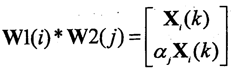
이에, LTE-A 표준에서는 최종 PMI 를 롱텀(long term) 및/또는 광대역(wideband) PMI 인 W1 와 숏텀(short term) 및/또는 서브밴드(sub-band) PMI 인 W2 둘로 나누어 설계하는 것으로 결정되었다.Accordingly, the LTE-A standard decides to design the final PMI by dividing it into W1, which is a long term and / or wideband PMI, and W2, which is a short term and / or sub-band PMI. It became.
상기 W1 및 W2 정보로부터 하나의 최종 PMI 를 구성하는 구조적 코드북 변환(hierarchical codebook transformation) 방식의 예시로 아래 수학식 8 과 같이 채널의 롱텀 공분산 행렬(long-term covariance matrix)를 이용할 수 있다.As an example of a hierarchical codebook transformation method constituting one final PMI from the W1 and W2 information, a long-term covariance matrix of a channel may be used as shown in
![]()
![]()
위 수학식 1에서 W2는 숏텀 PMI로서, 숏텀 채널 정보를 반영하기 위해 구성된 코드북의 코드워드이고, W은 최종 코드북의 코드워드이며, norm(A) 은 행렬 A 의 각 열의 노름(norm)이 1로 정규화(normalization)된 행렬을 의미한다.In
기존 W1과 W2의 구체적인 구조는 다음 수학식 9와 같다.The concrete structure of the existing W1 and W2 is expressed by the following equation (9).

수학식 9에서 코드워드의 구조는 교차 편파 안테나(cross polarized antenna)를 사용하고 안테나 간 간격이 조밀한 경우, 예를 들어, 통상 인접 안테나 간 거리가 신호 파장의 반 이하인 경우, 발생하는 채널의 상관관계(correlation) 특성을 반영하여 설계한 구조이다. 교차 편파 안테나의 경우 안테나를 수평 안테나 그룹(horizontal antenna group)과 수직 안테나 그룹(vertical antenna group)으로 구분 할 수 있는데, 각 안테나 그룹은 ULA(uniform linear array) 안테나의 특성을 가지며, 두 안테나 그룹은 공존(co-located)한다.The structure of the codeword in Equation (9) can be expressed by a cross polarized antenna, and when the spacing between antennas is dense, for example, when the distance between adjacent antennas is usually half or less of the signal wavelength, It is a structure that is designed by reflecting the characteristics of correlation. In the case of a cross-polarized antenna, antennas can be divided into horizontal antenna groups and vertical antenna groups. Each antenna group has characteristics of a uniform linear array (ULA) antenna. Co-located.
따라서 각 그룹의 안테나 간 상관관계 은 동일한 선형 위상 증가(linear phase increment) 특성을 가지며, 안테나 그룹 간 상관관계는 위상 회전(phase rotation)된 특성을 갖는다. 결국, 코드북은 채널을 양자화(quantization)한 값이기 때문에 채널의 특성을 그대로 반영하여 코드북을 설계하는 것이 필요하다. 설명의 편의를 위해 상기 상술한 구조로 만든 랭크 1 코드워드를 아래 수학식 10과 같이 예시할 수 있다.Therefore, the correlation between antennas of each group has the same linear phase increment characteristic, and the correlation between antenna groups has phase rotation characteristic. After all, since the codebook is a quantized value of the channel, it is necessary to design the codebook to reflect the characteristics of the channel. For convenience of description, the
위 수학식 10에서 코드워드는 송신 안테나의 개수 ![]()
![]()
![]()
![]()
![]()
![]()
![]()
![]()
LTE-A 표준과 같은 보다 진보된 통신 시스템에서는 MU-MIMO (multi-user MIMO)를 이용한 추가적인 다중 사용자 다이버시티(multi-user diversity)를 얻는 것이 추가되었다. MU-MIMO 에서는 안테나 도메인에서 다중화되는 단말들 간의 간섭이 존재하기 때문에, CSI 의 정확성 여부는 CSI 를 보고한 단말뿐만 아니라, 다중화되는 다른 단말의 간섭에도 큰 영향을 미칠 수 있다. 따라서, MU-MIMO 에서는 SU-MIMO 에 비하여 보다 정확한 CSI 보고가 요구된다.In more advanced communication systems, such as the LTE-A standard, it has been added to obtain additional multi-user diversity using multi-user MIMO (MU-MIMO). In MU-MIMO, since there is interference between terminals multiplexed in the antenna domain, the accuracy of CSI may have a significant effect on the interference of not only the UE reporting the CSI but also other multiplexed terminals. Therefore, MU-MIMO requires more accurate CSI reporting than SU-MIMO.
또한, CoMP JT 의 경우 여러 기지국이 특정 단말에게 동일한 데이터를 협력 전송하므로 이론적으로 안테나가 지리적으로 분산되어 있는 MIMO 시스템으로 간주할 수 있다. 즉, JT 에서 MU-MIMO 를 하는 경우도 단일 셀-MU-MIMO 와 마찬가지로 협력 스케줄링되는 단말들 간 간섭을 피하기 위해 높은 정확성의 채널 상태 정보가 요구 된다. CoMP CB 의 경우에도 역시 인접 셀이 서빙 셀에게 주는 간섭을 회피하기 위해서 정교한 채널 상태 정보가 요구된다.In addition, in the case of CoMP JT, since several base stations cooperatively transmit the same data to a specific terminal, it may theoretically be regarded as a MIMO system in which antennas are geographically dispersed. That is, in the case of MU-MIMO in JT, like the single cell-MU-MIMO, high accuracy channel state information is required in order to avoid interference between co-scheduled terminals. In the case of CoMP CB, sophisticated channel state information is also required to avoid interference caused by neighboring cells to the serving cell.
이하, 자원 특정 측정 기법에 관하여 설명한다.The resource specific measurement technique will be described below.
셀 간 간섭을 감소시키기 위한 하나의 방법으로서, 간섭 셀이 일부 물리 채널의 전송 전력을 줄이거나 채널 자체를 전송하지 않는 침묵 서브프레임 (이하, ABS(almost blank subframe)라고 지칭)을 사용하고, 피 간섭 셀이 이를 고려하여 UE 를 스케줄링하는 시간 도메인에서의 셀 간 간섭 완화 기법이 제안되었다. 여기서, ABS 로 지정된 서브프레임에서는 CRS 만 전송할 수 있도록 설정되는 것이 일반적이다.As one method for reducing inter-cell interference, an interfering cell uses a silent subframe (hereinafter referred to as an almost blank subframe) that does not reduce the transmit power of some physical channels or transmit the channel itself, An intercell interference mitigation technique in the time domain in which an interfering cell schedules a UE has been proposed. Here, it is common to set only CRS to be transmitted in a subframe designated by ABS.
이 경우 피 간섭 셀의 UE 입장에서는 간섭 정도가 서브프레임에 따라서 크게 변화하게 되는데, 각 서브프레임에서의 보다 정확한 RLM(radio link monitoring) 동작이나 RSRP(Reference Signal Received Power)/RSRQ(Reference Signal Received Quality) 등을 측정하는 RRM(radio resource management) 동작을 수행하거나, CSI(channel state information)를 측정하기 위해서, 상기 RLM 동작/ RRM 동작이 균일한 간섭 특성을 지니는 서브프레임들의 집합에서 수행되도록 제한되어야 한다. 따라서, 현재 3GPP LTE 표준문서에서는 자원 특정 측정을 위하여 2 개의 CSI 서브프레임 세트를 정의하고 있다.In this case, the interference level of the UE to be interfered with varies significantly depending on the subframe, and more accurate radio link monitoring (RLM) operation or reference signal received power (RSRP) / reference signal received quality (RSRQ) in each subframe. In order to perform RRM (radio resource management) operation for measuring CSI, etc., or to measure channel state information (CSI), the RLM operation / RRM operation should be limited to be performed in a set of subframes having uniform interference characteristics. . Therefore, the 3GPP LTE standard document currently defines two sets of CSI subframes for resource specific measurement.
이하, 전송 모드에 관하여 예시한다.Hereinafter, the transmission mode will be exemplified.
현재 3GPP LTE 표준문서, 구체적으로 3GPP TS 36.213 문서에서는 아래 표 1 및 표 2 와 같이 하향링크 전송 모드에 관하여 정의하고 있다. 또한, 아래 전송 모드는 상위 계층 시그널링, 즉 RRC 시그널링을 통하여 단말에게 설정된다.The current 3GPP LTE standard document, specifically the 3GPP TS 36.213 document, defines the downlink transmission mode as shown in Tables 1 and 2 below. Also, the lower transmission mode is set to the UE through higher layer signaling, i.e., RRC signaling.
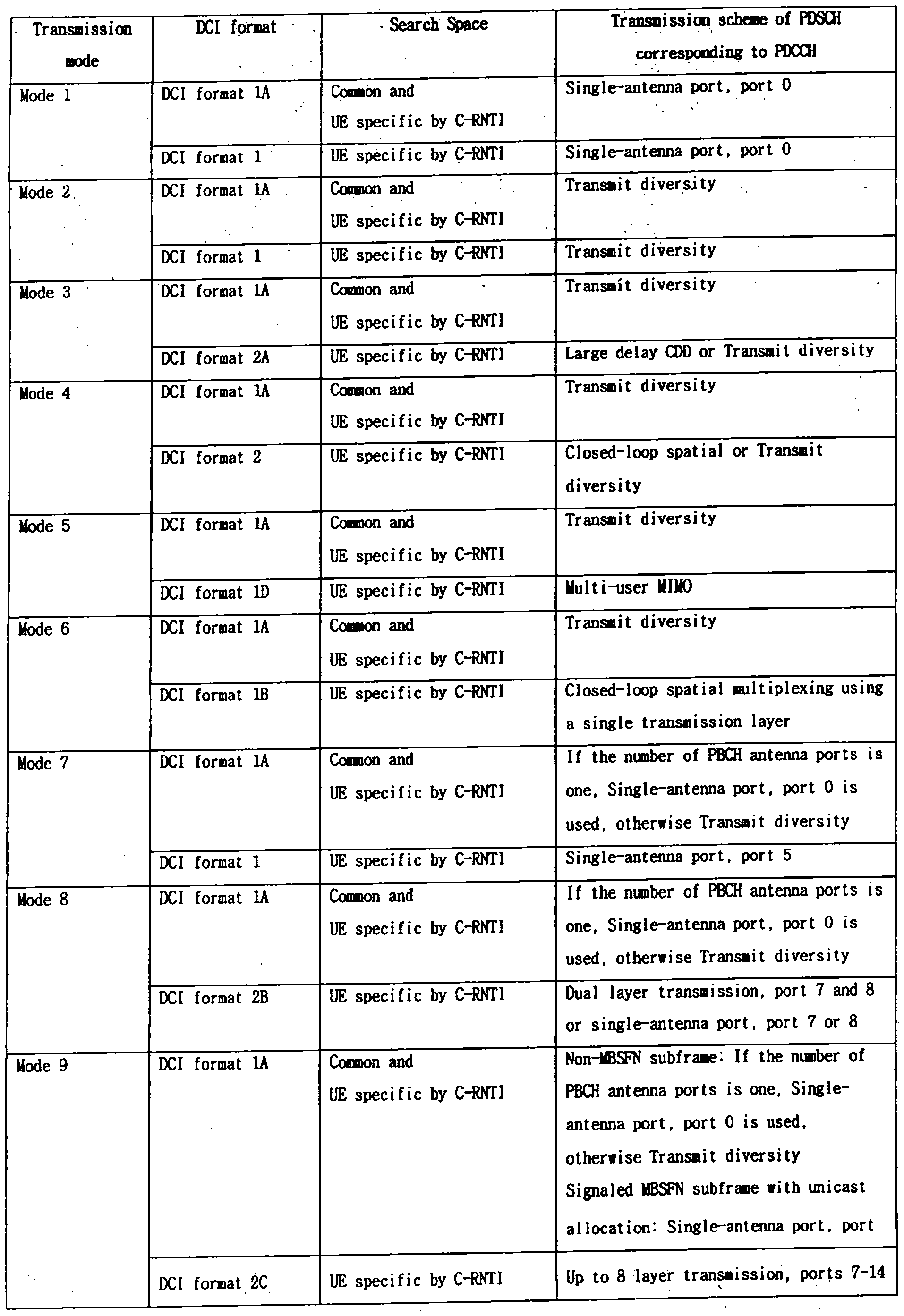

현재 3GPP LTE 표준문서에서는, PDCCH 를 마스킹된 RNTI 의 종류에 따른 DCI 포맷이 나타나 있으며, 특히 C-RNTI 와 SPS C-RNTI 의 경우, 전송 모드와 이에 대응하는 DCI 포맷, 즉 전송 모드 기반 DCI 포맷을 도시하고 있다. 또한, 각각의 전송 모드에 무관하게 적용될 수 있는 DCI 포맷 1A 가 정의되어 있다. 상기 표 1 은 PDCCH 를 마스킹된 RNTI 의 종류가 C-RNTI 인 경우를 예시한 것이며, 상기 표 2 는 PDCCH 를 마스킹된 RNTI 의 종류가 SPS C-RNTI 인 경우를 예시한 것이다.In the current 3GPP LTE standard document, the DCI format according to the type of the RNTI masked with the PDCCH is shown. Especially, in case of C-RNTI and SPS C-RNTI, the transmission mode and the corresponding DCI format, Respectively. In addition, a DCI format 1A is defined that can be applied regardless of each transmission mode. Table 1 illustrates a case where the type of the RNTI masked with the PDCCH is C-RNTI, and Table 2 illustrates a case where the type of the RNTI masked with the PDCCH is the SPS C-RNTI.
예를 들면, 표 1 에서 C-RNTI 로 마스킹된 PDCCH 를 단말 특정 검색 영역에서 블라인드 디코딩한 결과 DCI 포맷 1B 가 검출된다면, 단일 레이어를 이용한 폐루프 공간 다중화 기법으로 PDSCH 가 전송되었다고 가정하여 PDSCH 를 디코딩한다.For example, if the DCI format 1B is detected as a result of blind decoding of the PDCCH masked with the C-RNTI in Table 1, the PDSCH is decoded assuming that the PDSCH is transmitted using the closed-loop spatial multiplexing technique using a single layer do.
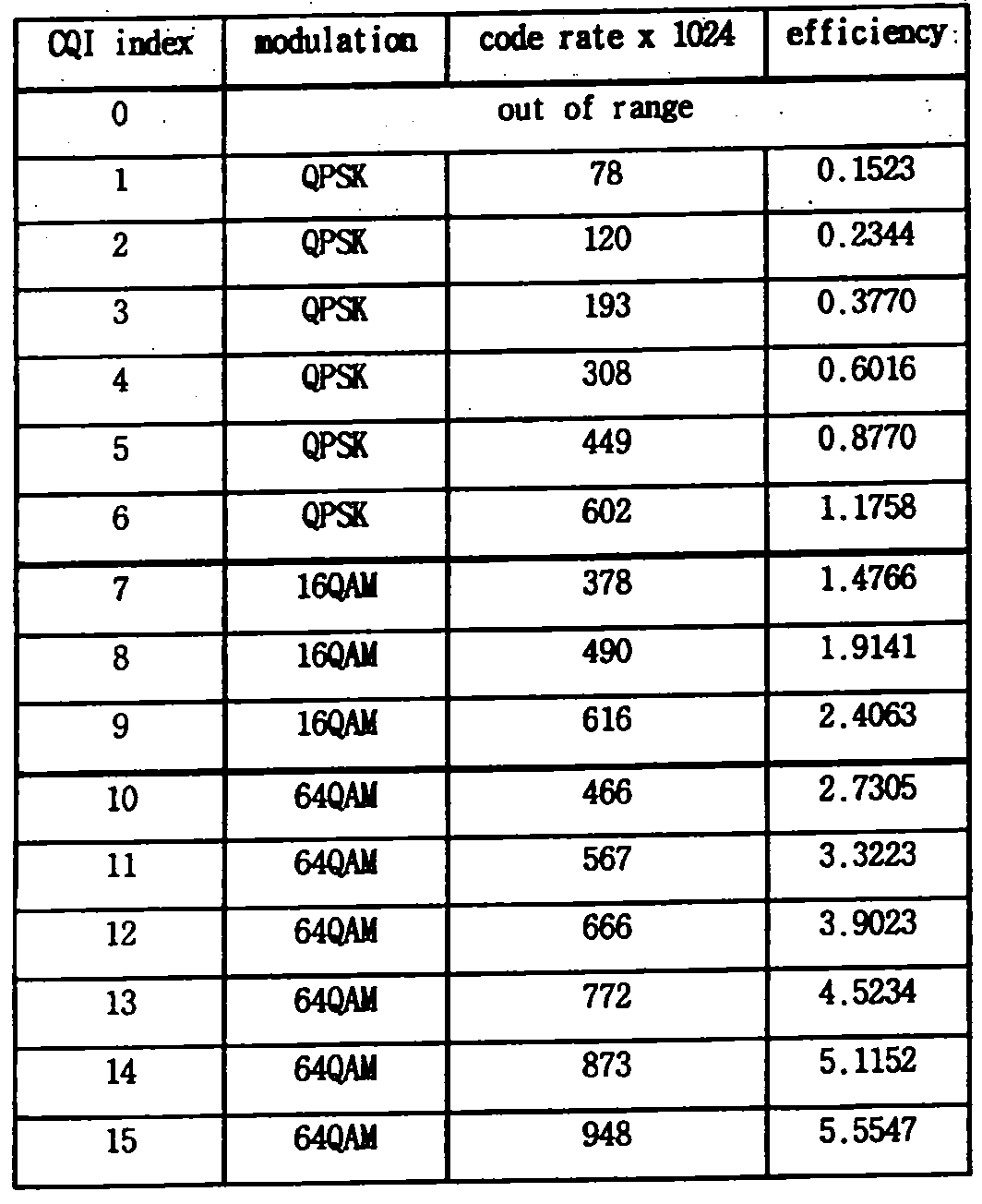
한편, 채널 품질 지시자(Channel Quality Indicator; CQI)를 기지국으로 보고하기 위하여, 단말은 기지국이 아래 표 3과 같은 전송 모드로 참조 신호를 전송한다는 가정하에 채널을 측정하여 CQI를 정보를 생성한다. 즉, 아래 표 3은 단말이 CQI 측정을 위하여 가정하는 기지국의 PDSCH 전송 모드를 나타낸다.Meanwhile, in order to report a channel quality indicator (CQI) to a base station, the terminal generates a CQI by measuring a channel under the assumption that the base station transmits a reference signal in a transmission mode as shown in Table 3 below. That is, Table 3 below shows the PDSCH transmission mode of the base station that the terminal assumes for CQI measurement.

예를 들어, 표 3에서 전송 모드 7은 빔포밍 전송 모드로 지칭되며, 단일 데이터 스트림, 즉 랭크 1의 전송을 지원한다. PBCH 안테나 포트가 복수개인 경우, CQI 측정을 위하여 기지국의 PDSCH 전송 모드는 전송 다이버시티(transmit diversity)로 가정된다. 또한, CQI는 아래 표 4와 같이 인덱스 형태로 기지국으로 피드백되며, 각 CQI 인덱스는 기지국은 피드백된 CQI에 대응하는 변조 기법 및 코딩 레이트와 같은 전송 포맷을 결정하여 단말로 하향링크 전송을 수행한다.For example, in Table 3,
본 발명에서는 기지국이 상향링크 자원(예를 들어, 상향링크 서브프레임) 또는 하향링크 자원(예를 들어, 하향링크 서브프레임)을 두 개 이상의 집합으로 구분한 상태에서 하향링크 데이터를 수신하거나 상향링크 데이터를 송신할 때 사용하는 전송 모드를 각 집합마다 별도로 설정하여, 서로 다른 서브프레임 집합에서는 서로 다른 전송 모드로 동작하도록 하는 것을 제안한다.In the present invention, the base station receives downlink data or receives uplink data in a state in which an uplink resource (for example, an uplink subframe) or a downlink resource (for example, a downlink subframe) is divided into two or more sets. It is proposed to set a transmission mode used for transmitting data separately for each set, so that different subframe sets operate in different transmission modes.
구체적으로, 기지국은 사전에 단말에게 RRC 시그널링과 같은 상위 계층 신호를 통해서 상항링크 자원 또는 하향링크 자원을 복수의 집합으로 구분할 수 있다. 예를 들어, 기지국은 전체 하항링크 서브프레임들을 서브프레임 집합 1 및 서브프레임 집합 2 로 구분하고, 단말로 하여금 각각의 서브프레임 집합에 대한 CSI(channel state information)를 피드백하도록 지시할 수 있다. 이러한 자원 분류의 이유 중 하나는 셀 간 간섭 차원에서 각 자원의 집합에서 단말이 겪는 간섭의 수준이 다르기 때문이다. 즉, 인접한 간섭 셀이 특정한 서브프레임 집합으로 ABS 을 설정한다면, 피 간섭 셀의 단말 입장에서는 간섭 셀의 ABS 전송 여부에 따라 채널 품질이 달라지게 된다. 따라서, 각 서브프레임마다 정확한 CSI 측정을 위해서는 서브프레임 집합 에 적합한, 즉 서브프레임 집합 특정 측정 기법이 적용되어야 한다. 다시 말해, 서로 다른 서브프레임 집합에서는 서로 다른 간섭이 존재한다는 가정하에 측정이 이루어져야 한다는 것이다.In detail, the base station may divide the uplink resource or the downlink resource into a plurality of sets in advance through a higher layer signal such as RRC signaling to the terminal. For example, the base station may divide all downlink subframes into subframe set 1 and subframe set 2, and instruct the terminal to feed back channel state information (CSI) for each subframe set. One of the reasons for such a resource classification is that the level of interference experienced by the UE in each resource set differs in terms of interference between cells. That is, if the adjacent interfering cells set the ABS to a specific subframe set, the channel quality of the interfering cell depends on whether the interfering cell transmits ABS. Therefore, for accurate CSI measurement in each subframe, a subframe set specific measurement technique suitable for the subframe set should be applied. In other words, measurements should be made on the assumption that different interferences exist in different sets of subframes.
따라서, 본 발명에서는 단말의 상항링크 전송 모드 또는 하향링크 전송 모드를 별도로 구분된 자원 집합, 즉 서브프레임 집합마다 별도로 설정할 것을 제안한다. 이런 자원 집합 특정 전송 모드의 설정은 아래와 같은 장점이 있다.Accordingly, the present invention proposes to separately set the uplink transmission mode or the downlink transmission mode of the UE for each resource set, that is, a subframe set. This resource set specific transmission mode configuration has the following advantages.
각 자원 집합 마다 단말이 겪는 간섭 수준이 다르므로, 각 자원 집합의 간섭 수준에 맞는 최적의 전송 모드를 개별적으로 설정할 수 있다. 예를 들어 인접 셀에서는 ABS 를 전송하도록 설정되어 매우 낮은 간섭이 발생하는 서브프레임 집합에서는 보다 안정적인 CSI 측정 및 피드백이 가능하다. 따라서, 전송 모드 9 과 같이 높은 전송 랭크를 지원할 수 있는 방식이 적절할 수 있다. 표 1 을 참조하면, 전송 모드 9 는 안테나 포트 7 내지 14 (여기서, 안테나 포트 7 내지 14 는 단말 특정 참조 신호인 DM-RS 의 안테나 포트를 지칭)에 기반하여 최대 8 레이어 전송을 지원함을 알 수 있다.Since the interference level experienced by the UE is different for each resource set, an optimal transmission mode suitable for the interference level of each resource set can be individually set. For example, neighboring cells are configured to transmit ABS, so that more stable CSI measurement and feedback are possible in a subframe set in which very low interference occurs. Therefore, a scheme capable of supporting a high transmission rank such as
반면, 인접 셀에서 ABS 가 전송되지 않도록 설정되어 간섭이 높아지는 서브프레임 집합에서는 인접 셀의 프리코딩 방식 등에 따라 발생 가능한 간섭 수준이 예측하기 어려울 정도로 변화할 수 있다. 이런 상황에서도 신뢰성 있는 패킷 전송이 가능한, 예를 들어, 전송 모드 2 의 전송 다이버시티 기법이 적절할 수 있다. 표 1 에서 전송 모드 2 는 전송 다이버시티를 지원함을 알 수 있다.On the other hand, in a subframe set in which interference is increased because ABS is not transmitted in a neighboring cell, an interference level that may occur according to a precoding scheme of the neighboring cell may change to be difficult to predict. In such a situation, for example, a transmission diversity scheme of
이하 도면을 참조하여, 보다 상세히 설명한다.With reference to the drawings, it will be described in more detail.
도 8 은 본 발명의 실시예에 따라 자원 특정 전송 모드를 적용한 예를 도시한다.8 illustrates an example of applying a resource specific transmission mode according to an embodiment of the present invention.
도 8 을 참조하면, 기지국이 지리적으로 떨어진 위치에 RRH(remote radio head)를 가지고 있는 경우에는 기지국과 RRH 의 협력 전송 방식 및/또는 참조 신호 설정(reference signal configuration)에 따라서 각 자원 집합의 속성에 적합한 전송 모드를 개별적으로 설정할 수 있다.Referring to FIG. 8, when the base station has a remote radio head (RRH) at a geographically separated location, attributes of each resource set are determined according to a cooperative transmission scheme and / or reference signal configuration between the base station and the RRH. The appropriate transmission mode can be set individually.
예를 들어, 도 8 의 (a)와 같이 기지국과 RRH 가 동일한 셀 식별자를 가지고 CRS 를 함께 전송하는 경우에, 제 1 서브프레임 집합이 CRS 를 데이터 영역에도 포함하는 서브프레임들로 구성되어 있다면, 제 1 서브프레임 집합에서는 기지국과 RRH 가 함께 전송하는 CRS 를 기반으로 하여 PDSCH 역시 기지국과 RRH 가 동시에 전송하도록 동작(이를 두 전송 포인트로부터의 협력 전송이라고 볼 수 있다)하는 것 바람직하다. 구체적으로, 도 8 의 (a)와 같은 경우에는 기지국과 RRH 는 모두 제 1 서브프레임 집합에서는 전송 모드 4 와 같이 CRS 기반의 PDSCH 전송을 수행하는 것이 바람직하다.For example, when the base station and the RRH transmit the CRS together with the same cell identifier as shown in FIG. 8A, if the first subframe set includes subframes including the CRS in the data region, In the first subframe set, it is preferable that the PDSCH also operates to simultaneously transmit the base station and the RRH based on the CRS transmitted by the base station and the RRH (which may be referred to as cooperative transmission from two transmission points). Specifically, in the case of (a) of FIG. 8, it is preferable that both the base station and the RRH perform CRS-based PDSCH transmission as in
반면, 도 8 의 (b)와 같이 제 2 서브프레임 집합이 CRS 를 데이터 영역에 포함하지 않는 MBSFN 서브프레임들로 구성되어 있다면, 제 2 서브프레임 집합에서는 단말 특정 참조 신호를 기반으로 PDSCH 가 전송되어야 한다. 이 경우, 기지국과 RRH 가 각각에게 가깝게 위치한 서로 다른 단말을 적절한 빔 포밍등의 프로세싱을 통하여 전송하는 것이, 시간/주파수 자원을 공간적으로 재활용하는 셀 스플릿팅 이득(cell splitting gain)을 얻을 수 있다는 점에서 바람직하다. 구체적으로, 도 8 의 (b)와 같은 경우에는 단말 특정 참조 신호 전송을 지원하는 전송 모드 9 으로 하향링크 전송을 이루어지는 것이 바람직하다.On the other hand, as shown in (b) of FIG. 8, if the second subframe set includes MBSFN subframes that do not include the CRS in the data region, the PDSCH should be transmitted based on the UE-specific reference signal in the second subframe set. do. In this case, transmitting different terminals located close to each other by the base station and the RRH through appropriate beamforming or the like can obtain a cell splitting gain that spatially recycles time / frequency resources. Preferred at Specifically, in the case of (b) of FIG. 8, it is preferable to perform downlink transmission in
한편, 자원 집합 특정 전송 모드를 적용하기 위하여는 아래와 같은 동작이 필요하다.Meanwhile, the following operation is required to apply a resource set specific transmission mode.
1) CSI 측정 및 CQI 산출1) CSI measurement and CQI calculation
단말은 각 자원 집합에 대한 CSI 를 측정하고 피드백하는 경우, 해당 자원 집합에 대하여 설정된 전송 모드를 가정하고 이에 따른 CQI 산출을 수행해야 한다. 여기에는 단말 특정 참조 신호의 오버헤드나 기지국의 프리코딩 방식 등이 포함될 수 있다. 단말은 매 CSI 보고 시점에서의 CSI 참조 자원을 포함하는 자원 집합에 설정된 전송 모드를 가정하고 CSI 를 측정하도록 구현된다.When measuring and feeding back CSI for each resource set, the UE assumes a transmission mode set for the corresponding resource set and performs CQI calculation accordingly. This may include the overhead of the UE-specific reference signal or the precoding scheme of the base station. The UE is implemented to assume the transmission mode set in the resource set including the CSI reference resource at every CSI reporting time and measure the CSI.
예를 들어, 비주기적 CSI 보고 동작의 경우, CSI 보고를 트리거링한 PDCCH 가 특정 서브프레임에서 전송된 경우, 상기 특정 서브프레임이 포함된 서브프레임 집합에 설정된 전송 모드를 가정하고 CSI 를 측정하도록 구현된다.For example, in the case of the aperiodic CSI reporting operation, when the PDCCH triggering the CSI reporting is transmitted in a specific subframe, it is implemented to assume the transmission mode set in the subframe set including the specific subframe and measure the CSI. .
2) 설정된 자원 집합 이외의 자원에서의 전송 모드2) Transmission mode in resources other than set resource set
기지국이 설정한 자원 집합이 모든 상향링크 자원 또는 하향링크 자원을 포함하지 못하는 경우가 발생할 수 있다. 이런 경우에도 해당 자원에 대한 전송 모드가 결정되어야 하며, 기지국이 어떠한 자원 집합에서 속하지 않는 자원을 위하여 전송 모드를 별도로 RRC 시그널링과 같은 상위 계층 신호를 통하여 알려줄 수 있다. 혹은 특정 자원 집합, 예를 들어 첫 번째 인덱스의 자원 집합의 전송 모드와 동일하다고 가정하는 방법도 고려할 수 있다.A resource set configured by a base station may not include all uplink resources or downlink resources. Even in this case, the transmission mode for the corresponding resource should be determined, and the base station may inform the transmission mode separately through an upper layer signal such as RRC signaling for a resource that does not belong to any resource set. Alternatively, a method may be considered that is assumed to be the same as a transmission mode of a specific resource set, for example, the resource set of the first index.
다른 예로는 특정 전송 모드를 기본 전송 모드로 설정하되, 특정 자원 집합에서 적용될 수 있는 전송 모드를 해당 자원 집합 정보 (예를 들어 서브프레임 패턴 정보)와 함께 시그널링할 수도 있다. 이러한 경우라면, 기지국이 설정한 자원 집합에 모든 상향링크 자원 또는 하향링크 자원을 포함하지 못하는 경우가 발생하지 않는다.As another example, a specific transmission mode may be set as a basic transmission mode, but a transmission mode applicable to a specific resource set may be signaled along with corresponding resource set information (for example, subframe pattern information). In such a case, the case in which all uplink resources or downlink resources are not included in the resource set configured by the base station does not occur.
3) 상향링크 전송 모드의 결정3) Determination of Uplink Transmission Mode
상향링크 전송 모드는 하향링크 서브프레임의 자원 집합 구분에 의하여 결정될 수 있다. 서브프레임 #n 에서 상향링크 스케줄링 정보인 UL 그랜트를 수신할 경우 이를 이용한 PUSCH 를 서브프레임 #n+k 에서 전송한다고 가정할 때, PUSCH 의 전송 모드는 해당 서브프레임에 대한 UL 그랜트를 전송하는 하향링크 서브프레임이 어떠한 서브프레임 집합, 즉 자원 집합에 포함되는 지 여부에 따라서 결정될 수 있다.The uplink transmission mode may be determined by classifying resource sets of downlink subframes. When a UL grant, which is uplink scheduling information, is received in subframe #n, assuming that a PUSCH using the UL grant is transmitted in subframe # n + k, the transmission mode of the PUSCH is a downlink that transmits a UL grant for the corresponding subframe. The subframe may be determined according to which subframe set, that is, included in the resource set.
예를 들어 서브프레임 #n 이 제 1 자원 집합에 속해있다면, 서브프레임 #n+k 에서는 제 1 자원 집합에 대하여 설정된 상향링크 전송 모드를 사용할 수 있다. 만일 제 1 자원 집합이 간섭 셀이 ABS 로 설정하는 서브프레임들이라면, 서브프레임 #n+k 에서는 인접 셀에서는 상향링크 전송이 없을 것이므로 간섭에 대한 고려 없이 UL MIMO 를 사용하는 전송 모드를 사용할 수 있다.For example, if the subframe #n belongs to the first resource set, the uplink transmission mode configured for the first resource set may be used in the subframe # n + k. If the first resource set is subframes in which the interfering cell is set to ABS, since there will be no uplink transmission in the neighboring cell in subframe # n + k, a transmission mode using UL MIMO may be used without considering interference.
반면 서브프레임 #n 이 제 2 자원 집합에 속해 있다면, 서브프레임 #n+k 에서는 제 2 자원 집합에 대해서 설정된 상향링크 전송 모드를 사용할 수 있는데, 만일 제 2 자원 집합이 간섭 셀이 ABS 로 설정하지 않는 일반 서브프레임들이라면, 일정 수준 이상의 간섭이 예상되므로 서브프레임 #n+k 에서는 MIMO 전송을 사용하지 않는 전송 모드가 바람직할 수 있다.On the other hand, if the subframe #n belongs to the second resource set, the uplink transmission mode configured for the second resource set may be used in the subframe # n + k, if the second resource set does not set the interference cell to ABS. In general subframes that do not have a certain level of interference, a transmission mode that does not use MIMO transmission may be preferable in subframe # n + k.
상기 설명한 본 발명의 변형의 하나로, 기지국과 단말은 각 서브프레임의 MBSFN 서브프레임 설정 여부에 따라서 각 서브프레임의 전송 모드를 설정할 수 있다. 기지국은 두 개의 전송 모드를 단말에게 설정하고 비(非)-MBSFN 서브프레임, 예를 들어 일반 서브프레임에서는 첫 번째 전송 모드(예를 들어, CRS 를 기반으로 하는 전송 모드)를, MBSFN 서브프레임에서는 두 번째 전송 모드(예를 들어, 단말 특정 참조 신호를 기반으로 하는 전송 모드)를 사용할 것을 지시할 수도 있다.As a variation of the present invention described above, the base station and the terminal may set the transmission mode of each subframe according to whether the MBSFN subframe of each subframe is set. The base station sets two transmission modes to the terminal and the first transmission mode (for example, a transmission mode based on CRS) in a non-MBSFN subframe, for example, in a normal subframe, and in a MBSFN subframe. It may be indicated to use a second transmission mode (eg, a transmission mode based on a UE-specific reference signal).
상기 설명한 바와 같이 최적의 전송 모드가 서브프레임 집합, 즉 자원 집합 별로 상이한 경우라면, 전송 모드 설정 및 CSI 보고 설정에 관련된 각종 파라미터들, 예를 들어 코드북 서브셋 제한 필드(codebook subset restriction field) 역시 자원 집합 별로 상이하게 설정해야 할 필요가 있다.As described above, if the optimal transmission mode is different for each subframe set, that is, for each resource set, various parameters related to the transmission mode setting and the CSI reporting setting, for example, a codebook subset restriction field, may also be used. It needs to be set differently.
단말은 기지국의 하향링크 데이터 전송에 적용될 프리코딩에 대한 정보를 제공하기 위한 목적으로 채널의 공간적 (다른 의미로 다중 안테나적) 특성을 피드백 함에 있어서 사전에 정의된 코드북을 사용한다. 여기서 코드북을 사용한다는 것은, 기지국과 단말은 유한한 개수의 코드워드가 정의된 코드북을 사전에 정의하고, 매 채널 정보 보고 시점에 있어서 기지국과 단말 사이의 채널을 효과적으로 표현할 수 있는 코드워드에 대한 인덱스를 피드백한다는 의미이다. 참고로, 하나의 코드워드는 한가지 채널 특성을 표현할 수 있다.The terminal uses a predefined codebook in feeding back the spatial (in other words, multi-antennaic) characteristics of the channel for the purpose of providing information on precoding to be applied to downlink data transmission of the base station. Here, using a codebook means that a base station and a terminal define a codebook in which a finite number of codewords are defined in advance, and an index for a codeword that can effectively express a channel between the base station and the terminal at every channel information report point. It means to feed back. For reference, one codeword may express one channel characteristic.
여기서 코드북 서브셋 제한이란 기지국은 일련의 코드워드로 구성된 코드북 서브셋을 단말로 전송하고, 단말로 하여금 해당 코드북 서브셋에 포함된 코드워드만을 사용하여 채널 보고 동작을 수행할 것을 지시하는 동작을 의미한다. 이러한 코드북 서브셋 제한에 의하면, 기지국은 특정한 방향의 코드워드만을 프리코딩에 활용하면서, 이러한 사실을 단말에게 알려서 적절한 채널 보고를 수행하도록 할 수 있다.Here, the codebook subset restriction refers to an operation of transmitting a codebook subset consisting of a series of codewords to a terminal and instructing the terminal to perform a channel report operation using only codewords included in the corresponding codebook subset. According to the codebook subset limitation, the base station may use only the codewords in a specific direction for precoding, and inform the terminal of this fact so as to perform an appropriate channel report.
상기 설명한 코드북 서브셋 제한에 있어서, 기지국은 자원 집합 별로 서로 다른 코드북 서브셋을 알려주는 동작이 도움이 될 수 있다. 일례로, 제 1 기지국이 제 1 서브프레임 집합에서는 제 2 기지국과 셀 간 간섭 완화 동작을 수행하고, 제 2 서브프레임 집합에서는 제 3 기지국과 셀 간 간섭 완화 동작을 수행하는 경우를 가정한다. 이러한 가정 하에서, 제 1 기지국이 제 2 기지국 및 제 3 기지국과 같은 협력 기지국들 각각에 간섭을 미치는 프리코딩 행렬이 상이하기 때문에, 두 서브프레임 집합에서 사용할 수 있는 코드북 서브셋은 상이할 수 있다. 따라서 보다 효과적인 채널 측정 보고를 위해서 기지국은 복수의 코드북 서브셋 제한 필드를 단말에게 전송하고, 단말은 각 자원 (혹은 서브프레임) 집합 별로 서로 다른 코드북 서브셋을 사용하도록 동작하는 것이 바람직하다.In the codebook subset limitation described above, it may be helpful for the base station to inform different codebook subsets for each resource set. For example, it is assumed that the first base station performs the interference mitigation operation between the second base station and the cell in the first subframe set, and performs the interference mitigation operation between the third base station and the cell in the second subframe set. Under this assumption, because the precoding matrix that the first base station interferes with each of the cooperative base stations, such as the second base station and the third base station, is different, the codebook subset that can be used in the two subframe sets may be different. Accordingly, for more effective channel measurement reporting, the base station transmits a plurality of codebook subset restriction fields to the terminal, and the terminal is operable to use different codebook subsets for each resource (or subframe) set.
구현 예로서, 기지국은 각 자원 (혹은 서브프레임) 집합에서 활용될 코드북 서브셋 제한 필드를 전송하되, 이러한 자원 집합과 코드북 서브셋 제한 필드를 여러 개 전송할 수 있도록 허용하는 방안이 있다.As an implementation example, the base station transmits a codebook subset restriction field to be utilized in each resource (or subframe) set, but allows a plurality of such resource set and codebook subset restriction fields to be transmitted.
경우에 따라서 기지국이 설정한 모든 자원 집합이 모든 하향링크 자원을 포함하지 못할 수도 있으며, 이런 경우에는 특정 자원이 어느 자원 집합에도 포함되지 않을 수 있다. 이런 경우에도 해당 자원에 대한 코드북 서브셋 제한이 결정되어야 하며, 기지국이 어느 자원 집합에도 속하지 않는 자원에 대한 코드북 서브셋을 별도로 RRC 시그널링과 같은 상위 계층 신호를 통하여 알려줄 수도 있다. 혹은 특정 자원 집합(예를 들어 첫번째 인덱스를 가지는 자원 집합)의 코드북 서브셋과 동일하다고 가정할 수 있다.In some cases, all resource sets set by the base station may not include all downlink resources. In this case, a specific resource may not be included in any resource set. In this case, the codebook subset restriction on the corresponding resource should be determined, and the base station may separately inform the codebook subset of the resource not belonging to any resource set through higher layer signals such as RRC signaling. Or it may be assumed to be the same as the codebook subset of a specific resource set (for example, the resource set having the first index).
다른 방법으로는 특정한 코드북 서브셋을 기본 코드북 서브셋로 설정하되 특정한 자원 집합에서 적용이 될 코드북 서브셋을 별도로 해당 자원 집합 정보와 함께 시그널링할 수도 있다.Alternatively, a specific codebook subset may be set as a basic codebook subset, but a codebook subset to be applied in a specific resource set may be separately signaled along with corresponding resource set information.
자원 특정적인 코드북 서브셋 제한을 적용하는 경우, 단말은 하향링크에 대한 프리코딩 정보를 피드백 할 때 해당 피드백 시점에서 타겟팅하는 자원 집합에 대해서 사용하도록 규정된 코드북 서브셋을 사용해야 한다. 예를 들어, 단말은 매 피드백 시점에서, 해당 시점의 CSI 참조 자원을 포함하는 자원 집합에서 사용하도록 규정된 코드북 서브셋을 사용하여, 해당 코드북 서브셋에서 허용된 코드워드만을 피드백하도록 동작할 수 있다.When the resource-specific codebook subset restriction is applied, the terminal should use a codebook subset defined to be used for a resource set that is targeted at the corresponding feedback point when feeding back downlink precoding information. For example, the UE may operate to feed back only the codewords allowed in the codebook subset by using the codebook subset defined to be used in the resource set including the CSI reference resource at that time point at every feedback time point.
상기 설명한 전송 모드 설정 및 CSI 보고 설정에 관련된 각종 파라미터의 또 다른 하나로 상향링크 채널 정보 획득을 위한 (혹은 하향링크와 상향링크 사이의 대칭성을 이용하여 하향링크 채널 정보 획득을 위한) 사운딩 참조 신호(SRS) 관련 파라미터가 있다.The sounding reference signal for acquiring uplink channel information (or for acquiring downlink channel information using symmetry between downlink and uplink) is another one of various parameters related to the transmission mode setting and the CSI report setting described above. SRS) related parameters.
기지국은 복수의 SRS 파라미터 집합(예를 들어, SRS 전송 주기, 서브프레임 오프셋, 주파수 호핑 패턴, SRS 콤(comb) 인덱스, SRS 전송 대역폭, 프리코딩 정보 등)를 단말에게 알려주고, SRS 가 전송되는 자원 집합에 따라서 서로 다른 파라미터 집합을 사용하도록 동작할 수 있다. 특히 PDCCH 에 의해서 전송이 트리거링되는 비주기적(aperiodic) SRS 의 경우에, SRS 전송을 트리거링하는 PDCCH 가 전송된 자원 집합에 맵핑되는 SRS 파라미터 집합을 사용하는 방식으로 자원 특정적 SRS 전송을 구현할 수 있다.The base station informs the user equipment of a plurality of SRS parameter sets (eg, SRS transmission period, subframe offset, frequency hopping pattern, SRS comb index, SRS transmission bandwidth, precoding information, etc.), and a resource for transmitting the SRS. Depending on the set, you can operate to use different sets of parameters. In particular, in the case of an aperiodic SRS in which transmission is triggered by the PDCCH, resource-specific SRS transmission may be implemented by using an SRS parameter set mapped to a resource set in which the PDCCH triggering the SRS transmission is transmitted.
한편, 본 발명은 동적 자원 할당 기법에도 적용할 수 있다. 구체적으로, 시스템 정보로 설정된 상향링크 자원(예를 들어, FDD 인 경우 상향 링크 밴드, TDD 인 경우 상향링크 서브프레임)을 동적으로 하향링크 자원으로 변경하는 경우, 혹은 시스템 정보로 설정된 하향링크 자원을 동적으로 상향링크 자원으로 변경하는 경우에도 본 발명이 적용될 수 있다. 이러한 동적 자원 변경 방법은 하향링크 데이터가 순간적으로 증가한 경우 혹은 상향링크 데이터가 순간적으로 증가한 경우에 대처할 수 있는 유용한 기법이다.Meanwhile, the present invention can also be applied to a dynamic resource allocation scheme. In detail, when an uplink resource (eg, an uplink band in case of FDD, an uplink subframe in case of TDD) is dynamically changed to a downlink resource, or when the downlink resource set in system information is changed. The present invention can be applied even when dynamically changing to uplink resources. This dynamic resource change method is a useful technique to cope with the case where the downlink data is instantaneously increased or the uplink data is instantaneously increased.
상향링크 자원을 동적으로 하향링크 자원으로 변경하는 경우를 예시하면, 하향링크 자원 자체를 1) 원래 하향 링크 자원으로 설정된 것과 2) 원래는 상향 링크 자원으로 설정되었으나 하향 링크 자원으로 차용되는 것으로 구분할 수 있다. 이 경우, 각 자원의 간섭 속성 등이 상이할 것이므로 서로 다른 전송 모드를 사용하는 것이 유리하다.For example, when an uplink resource is dynamically changed to a downlink resource, the downlink resource itself may be classified into 1) an original downlink resource and 2) an original uplink resource but borrowed as a downlink resource. have. In this case, it is advantageous to use different transmission modes because interference properties of each resource will be different.
도 9 은 본 발명의 일 실시예에 따른 통신 장치의 블록 구성도를 예시한다.9 illustrates a block diagram of a communication device according to an embodiment of the present invention.
도 9 을 참조하면, 통신 장치(900)는 프로세서(910), 메모리(920), RF 모듈(930), 디스플레이 모듈(940) 및 사용자 인터페이스 모듈(950)을 포함한다.Referring to FIG. 9, the
통신 장치(900)는 설명의 편의를 위해 도시된 것으로서 일부 모듈은 생략될 수 있다. 또한, 통신 장치(900)는 필요한 모듈을 더 포함할 수 있다. 또한, 통신 장치(900)에서 일부 모듈은 보다 세분화된 모듈로 구분될 수 있다. 프로세서(910)는 도면을 참조하여 예시한 본 발명의 실시 예에 따른 동작을 수행하도록 구성된다. 구체적으로, 프로세서(910)의 자세한 동작은 도 1 내지 도 8 에 기재된 내용을 참조할 수 있다.The
메모리(920)는 프로세서(910)에 연결되며 오퍼레이팅 시스템, 어플리케이션, 프로그램 코드, 데이터 등을 저장한다. RF 모듈(930)은 프로세서(910)에 연결되며 기저대역 신호를 무선 신호를 변환하거나 무선신호를 기저대역 신호로 변환하는 기능을 수행한다. 이를 위해, RF 모듈(930)은 아날로그 변환, 증폭, 필터링 및 주파수 상향 변환 또는 이들의 역과정을 수행한다. 디스플레이 모듈(940)은 프로세서(910)에 연결되며 다양한 정보를 디스플레이한다. 디스플레이 모듈(940)은 이로 제한되는 것은 아니지만 LCD(Liquid Crystal Display), LED(Light Emitting Diode), OLED(Organic Light Emitting Diode)와 같은 잘 알려진 요소를 사용할 수 있다. 사용자 인터페이스 모듈(950)은 프로세서(910)와 연결되며 키패드, 터치 스크린 등과 같은 잘 알려진 사용자 인터페이스의 조합으로 구성될 수 있다.The
이상에서 설명된 실시예들은 본 발명의 구성요소들과 특징들이 소정 형태로 결합된 것들이다. 각 구성요소 또는 특징은 별도의 명시적 언급이 없는 한 선택적인 것으로 고려되어야 한다. 각 구성요소 또는 특징은 다른 구성요소나 특징과 결합되지 않은 형태로 실시될 수 있다. 또한, 일부 구성요소들 및/또는 특징들을 결합하여 본 발명의 실시예를 구성하는 것도 가능하다. 본 발명의 실시예들에서 설명되는 동작들의 순서는 변경될 수 있다. 어느 실시예의 일부 구성이나 특징은 다른 실시예에 포함될 수 있고, 또는 다른 실시예의 대응하는 구성 또는 특징과 교체될 수 있다. 특허청구범위에서 명시적인 인용 관계가 있지 않은 청구항들을 결합하여 실시예를 구성하거나 출원 후의 보정에 의해 새로운 청구항으로 포함시킬 수 있음은 자명하다.The embodiments described above are those in which the elements and features of the present invention are combined in a predetermined form. Each component or feature shall be considered optional unless otherwise expressly stated. Each component or feature may be implemented in a form that is not combined with other components or features. It is also possible to construct embodiments of the present invention by combining some of the elements and / or features. The order of the operations described in the embodiments of the present invention may be changed. Some configurations or features of certain embodiments may be included in other embodiments, or may be replaced with corresponding configurations or features of other embodiments. It is clear that the claims that are not expressly cited in the claims may be combined to form an embodiment or be included in a new claim by an amendment after the application.
본 문서에서 기지국에 의해 수행된다고 설명된 특정 동작은 경우에 따라서는 그 상위 노드(upper node)에 의해 수행될 수 있다. 즉, 기지국을 포함하는 복수의 네트워크 노드들(network nodes)로 이루어지는 네트워크에서 단말과의 통신을 위해 수행되는 다양한 동작들은 기지국 또는 기지국 이외의 다른 네트워크 노드들에 의해 수행될 수 있음은 자명하다. 기지국은 고정국(fixed station), Node B, eNode B(eNB), 억세스 포인트(access point) 등의 용어에 의해 대체될 수 있다.The specific operation described herein as being performed by the base station may be performed by its upper node, in some cases. That is, it is apparent that various operations performed for communication with a terminal in a network including a plurality of network nodes including a base station can be performed by a network node other than the base station or the base station. A base station may be replaced by terms such as a fixed station, a Node B, an eNode B (eNB), an access point, and the like.
본 발명에 따른 실시예는 다양한 수단, 예를 들어, 하드웨어, 펌웨어(firmware), 소프트웨어 또는 그것들의 결합 등에 의해 구현될 수 있다. 하드웨어에 의한 구현의 경우, 본 발명의 일 실시예는 하나 또는 그 이상의 ASICs(application specific integrated circuits), DSPs(digital signal processors), DSPDs(digital signal processing devices), PLDs(programmable logic devices), FPGAs(field programmable gate arrays), 프로세서, 콘트롤러, 마이크로 콘트롤러, 마이크로 프로세서 등에 의해 구현될 수 있다.Embodiments in accordance with the present invention may be implemented by various means, for example, hardware, firmware, software, or a combination thereof. In the case of hardware implementation, an embodiment of the present invention may include one or more application specific integrated circuits (ASICs), digital signal processors (DSPs), digital signal processing devices (DSPDs), programmable logic devices (PLDs) field programmable gate arrays, processors, controllers, microcontrollers, microprocessors, and the like.
펌웨어나 소프트웨어에 의한 구현의 경우, 본 발명의 일 실시예는 이상에서 설명된 기능 또는 동작들을 수행하는 모듈, 절차, 함수 등의 형태로 구현될 수 있다. 소프트웨어 코드는 메모리 유닛에 저장되어 프로세서에 의해 구동될 수 있다. 상기 메모리 유닛은 상기 프로세서 내부 또는 외부에 위치하여, 이미 공지된 다양한 수단에 의해 상기 프로세서와 데이터를 주고 받을 수 있다.In the case of implementation by firmware or software, an embodiment of the present invention may be implemented in the form of a module, procedure, function, etc. that performs the functions or operations described above. The software code can be stored in a memory unit and driven by the processor. The memory unit may be located inside or outside the processor, and may exchange data with the processor by various well-known means.
본 발명은 본 발명의 특징을 벗어나지 않는 범위에서 다른 특정한 형태로 구체화될 수 있음은 당업자에게 자명하다. 따라서, 상기의 상세한 설명은 모든 면에서 제한적으로 해석되어서는 아니되고 예시적인 것으로 고려되어야 한다. 본 발명의 범위는 첨부된 청구항의 합리적 해석에 의해 결정되어야 하고, 본 발명의 등가적 범위 내에서의 모든 변경은 본 발명의 범위에 포함된다.It will be apparent to those skilled in the art that the present invention may be embodied in other specific forms without departing from the spirit of the invention. Accordingly, the above detailed description should not be construed as limiting in all aspects and should be considered as illustrative. The scope of the invention should be determined by reasonable interpretation of the appended claims, and all changes within the equivalent scope of the invention are included in the scope of the invention.
[산업상 이용가능성][Industrial applicability]
상술한 바와 같은 무선 통신 시스템에서 자원 특정 전송 모드 결정 방법 및 이를 위한 장치는 3GPP LTE 시스템에 적용되는 예를 중심으로 설명하였으나, 3GPP LTE 시스템 이외에도 다양한 무선 통신 시스템에 적용하는 것이 가능하다.Although the method and apparatus for determining a resource specific transmission mode in the wireless communication system as described above have been described with reference to an example applied to the 3GPP LTE system, it is possible to apply to various wireless communication systems in addition to the 3GPP LTE system.
Claims (10)
상기 기지국으로부터 복수의 서브프레임 집합에 관한 정보를 수신하는 단계;
상기 기지국으로부터 상기 복수의 서브프레임 집합 각각에 대응하는 전송 모드에 관한 정보를 수신하는 단계; 및
상기 복수의 서브프레임 집합 중 특정 서브프레임 집합에 속하는 서브프레임에서, 상기 특정 서브프레임 집합에 대응하는 전송 모드에 기반하여, 상기 기지국으로부터 신호를 송수신하는 단계를 포함하는 것을 특징으로 하는,
신호 송수신 방법.A method for transmitting and receiving signals between a terminal and a base station in a wireless communication system,
Receiving information regarding a plurality of subframe sets from the base station;
Receiving information on a transmission mode corresponding to each of the plurality of subframe sets from the base station; And
And transmitting and receiving a signal from the base station in a subframe belonging to a specific subframe set among the plurality of subframe sets, based on a transmission mode corresponding to the specific subframe set.
/ RTI >
상기 복수의 서브프레임 집합 각각은,
인접 기지국으로 인하여 발생할 수 있는 간섭 레벨이 서로 다른 것을 특징으로 하는,
신호 송수신 방법.The method of claim 1,
Each of the plurality of subframe sets,
Characterized in that the interference level may be caused by the neighboring base station is different,
/ RTI >
상기 신호를 송수신하는 단계는,
상기 기지국으로부터 특정 서브프레임에서 하향링크 신호를 수신하는 경우, 상기 특정 서브프레임이 속하는 서브프레임 집합에 대응하는 전송 모드로 상기 하향링크 신호가 수신되는 가정하여, 상기 하향링크 신호를 디코딩하는 단계를 포함하는 것을 특징으로 하는,
신호 송수신 방법.The method of claim 1,
The step of transmitting /
Decoding the downlink signal assuming that the downlink signal is received in a transmission mode corresponding to a set of subframes to which the specific subframe belongs when receiving a downlink signal from the base station in a specific subframe; Characterized by
/ RTI >
상기 신호를 송수신하는 단계는,
상기 기지국으로 특정 서브프레임에서 상향링크 신호를 송신하는 경우, 상기 특정 서브프레임과 연계된 하향링크 서브프레임이 속하는 서브프레임 집합에 대응하는 전송 모드로 상기 상향링크 신호를 송신하는 단계를 포함하는 것을 특징으로 하는,
신호 송수신 방법.The method of claim 1,
The step of transmitting /
When transmitting an uplink signal in a specific subframe to the base station, transmitting the uplink signal in a transmission mode corresponding to a set of subframes to which the downlink subframe associated with the specific subframe belongs. Made,
/ RTI >
상기 복수의 서브프레임 중 하나에 대응하는 전송 모드는,
셀 특정 참조 신호에 기반하여, 상기 기지국과 인접 기지국으로부터 협력 전송 신호를 수신하기 위한 전송 모드이고,
상기 복수의 서브프레임 중 다른 하나에 대응하는 전송 모드는,
단말 특정 참조 신호에 기반하여, 상기 기지국으로부터 신호를 수신하기 위한 전송 모드인 것을 특징으로 하는,
신호 송수신 방법.The method of claim 1,
Transmission mode corresponding to one of the plurality of subframes,
A transmission mode for receiving a cooperative transmission signal from the base station and a neighboring base station based on a cell specific reference signal,
The transmission mode corresponding to the other one of the plurality of subframes is:
Based on a terminal specific reference signal, characterized in that the transmission mode for receiving a signal from the base station,
/ RTI >
기지국과 신호를 송수신하기 위한 무선 통신 모듈; 및
상기 신호를 처리하기 위한 프로세서를 포함하고,
상기 무선 통신 모듈은,
기지국으로부터 복수의 서브프레임 집합에 관한 정보를 수신하고, 상기 기지국으로부터 상기 복수의 서브프레임 집합 각각에 대응하는 전송 모드에 관한 정보를 수신하고,
상기 프로세서는,
상기 복수의 서브프레임 집합 중 특정 서브프레임 집합에 속하는 서브프레임에서, 상기 특정 서브프레임 집합에 대응하는 전송 모드에 기반하여, 상기 기지국으로부터 신호를 송수신하도록 상기 무선 통신 모듈을 제어하는 것을 특징으로 하는,
단말 장치.As a terminal device in a wireless communication system,
A wireless communication module for transmitting and receiving a signal with a base station; And
And a processor for processing the signal,
The wireless communication module includes:
Receiving information about a plurality of subframe sets from a base station, receiving information about a transmission mode corresponding to each of the plurality of subframe sets from the base station,
The processor comprising:
And controlling the wireless communication module to transmit and receive a signal from the base station in a subframe belonging to a specific subframe set among the plurality of subframe sets, based on a transmission mode corresponding to the specific subframe set.
Terminal device.
상기 복수의 서브프레임 집합 각각은,
인접 기지국으로 인하여 발생할 수 있는 간섭 레벨이 서로 다른 것을 특징으로 하는,
단말 장치.The method according to claim 6,
Each of the plurality of subframe sets,
Characterized in that the interference level may be caused by the neighboring base station is different,
Terminal device.
상기 프로세서는,
상기 기지국으로부터 특정 서브프레임에서 하향링크 신호를 수신하는 경우, 상기 특정 서브프레임이 속하는 서브프레임 집합에 대응하는 전송 모드로 상기 하향링크 신호가 수신되는 가정하여, 상기 하향링크 신호를 디코딩하는 것을 특징으로 하는,
단말 장치.The method according to claim 6,
The processor comprising:
When the downlink signal is received from the base station in a specific subframe, the downlink signal is decoded on the assumption that the downlink signal is received in a transmission mode corresponding to the subframe set to which the specific subframe belongs. doing,
Terminal device.
상기 프로세서는,
상기 기지국으로 특정 서브프레임에서 상향링크 신호를 송신하는 경우, 상기 특정 서브프레임과 연계된 하향링크 서브프레임이 속하는 서브프레임 집합에 대응하는 전송 모드로 상기 상향링크 신호를 송신하도록 상기 무선 통신 모듈을 제어하는 것을 특징으로 하는,
단말 장치.The method according to claim 6,
The processor comprising:
When the uplink signal is transmitted to the base station in a specific subframe, the wireless communication module is controlled to transmit the uplink signal in a transmission mode corresponding to a set of subframes to which the downlink subframe associated with the specific subframe belongs. Characterized by
Terminal device.
상기 복수의 서브프레임 중 하나에 대응하는 전송 모드는,
셀 특정 참조 신호에 기반하여, 상기 기지국과 인접 기지국으로부터 협력 전송 신호를 수신하기 위한 전송 모드이고,
상기 복수의 서브프레임 중 다른 하나에 대응하는 전송 모드는,
단말 특정 참조 신호에 기반하여, 상기 기지국으로부터 신호를 수신하기 위한 전송 모드인 것을 특징으로 하는,
단말 장치.The method according to claim 6,
Transmission mode corresponding to one of the plurality of subframes,
A transmission mode for receiving a cooperative transmission signal from the base station and a neighboring base station based on a cell specific reference signal,
The transmission mode corresponding to the other one of the plurality of subframes is:
Based on a terminal specific reference signal, characterized in that the transmission mode for receiving a signal from the base station,
Terminal device.
Applications Claiming Priority (5)
| Application Number | Priority Date | Filing Date | Title |
|---|---|---|---|
| US201161469079P | 2011-03-29 | 2011-03-29 | |
| US61/469,079 | 2011-03-29 | ||
| US201161479413P | 2011-04-27 | 2011-04-27 | |
| US61/479,413 | 2011-04-27 | ||
| PCT/KR2012/002211 WO2012134140A2 (en) | 2011-03-29 | 2012-03-27 | Method for deciding resource-specific transmission mode in wireless communication system and apparatus for same |
Publications (2)
| Publication Number | Publication Date |
|---|---|
| KR20130143105A true KR20130143105A (en) | 2013-12-30 |
| KR101835331B1 KR101835331B1 (en) | 2018-03-07 |
Family
ID=46932101
Family Applications (1)
| Application Number | Title | Priority Date | Filing Date |
|---|---|---|---|
| KR1020137019735A KR101835331B1 (en) | 2011-03-29 | 2012-03-27 | Method for deciding resource-specific transmission mode in wireless communication system and apparatus for same |
Country Status (7)
| Country | Link |
|---|---|
| US (1) | US10499372B2 (en) |
| EP (1) | EP2675082B1 (en) |
| JP (3) | JP5735666B2 (en) |
| KR (1) | KR101835331B1 (en) |
| CN (2) | CN105610483B (en) |
| CA (1) | CA2827075C (en) |
| WO (1) | WO2012134140A2 (en) |
Families Citing this family (25)
| Publication number | Priority date | Publication date | Assignee | Title |
|---|---|---|---|---|
| EP2764224B1 (en) | 2011-10-03 | 2019-04-17 | Volvo Truck Corporation | Internal combustion engine system and method for increasing the temperature in at least one part of the internal combustion engine system |
| CN110049573B (en) * | 2012-01-17 | 2022-09-09 | 中兴通讯股份有限公司 | Wireless communication method, communication device and communication system |
| US20130303230A1 (en) * | 2012-05-10 | 2013-11-14 | Samsung Electronics Co., Ltd | Method and apparatus for aggregated cqi for coordinated multipoint transmission |
| CN114944892A (en) | 2013-01-03 | 2022-08-26 | 苹果公司 | User equipment and base station |
| US9521670B2 (en) * | 2013-03-05 | 2016-12-13 | Marvell World Trade Ltd. | Signal decoding in the presence of almost-blank subframes (ABS) |
| CN104521301B (en) * | 2013-08-02 | 2018-10-19 | 华为技术有限公司 | Configure the method and apparatus of wireless telecommunication system signal transmission mode |
| CN105340191B (en) * | 2013-12-30 | 2021-08-20 | 华为技术有限公司 | Data transmission method and device |
| WO2015126027A1 (en) * | 2014-02-18 | 2015-08-27 | 엘지전자 주식회사 | Method for transreceiving signal using user-specific flexible tdd technology in wireless communication system and device for same |
| US9775071B2 (en) * | 2014-02-24 | 2017-09-26 | Qualcomm Incorporated | TDD configurations and eIMTA in LTE |
| WO2015170924A1 (en) | 2014-05-09 | 2015-11-12 | 엘지전자 주식회사 | Method for transmitting and receiving d2d signal in wireless communication system, and apparatus therefor |
| CN104066196B (en) * | 2014-06-30 | 2018-07-13 | 华为技术有限公司 | Determine the method and apparatus for drawing and selecting radio frequency unit RRU |
| CN105515732B (en) * | 2014-09-24 | 2018-01-09 | 上海朗帛通信技术有限公司 | A kind of method and apparatus for multi-antenna communication in UE, base station |
| US10383155B2 (en) * | 2015-05-07 | 2019-08-13 | Lg Electronics Inc. | Method and apparatus for performing sidelink transmission based on contention based scheduling request in wireless communication system |
| US9705580B2 (en) | 2015-05-14 | 2017-07-11 | Sprint Communications Company L.P. | Wireless communication device control over wireless network antenna configurations |
| US10763925B2 (en) | 2015-11-11 | 2020-09-01 | Samsung Electronics Co., Ltd. | Method and apparatus for reduced feedback MIMO |
| EP3193468B1 (en) * | 2016-01-13 | 2018-08-22 | Mitsubishi Electric R&D Centre Europe B.V. | Method for quantizing an interference profile for a wireless telecommunication system along a path that a moving device takes |
| KR20180112796A (en) * | 2016-02-24 | 2018-10-12 | 삼성전자주식회사 | Method and apparatus for channel state information(csi) reporting |
| JP6749465B2 (en) * | 2016-07-07 | 2020-09-02 | 華為技術有限公司Huawei Technologies Co.,Ltd. | Data transmission method, user equipment, and base station |
| US20180124830A1 (en) * | 2016-11-03 | 2018-05-03 | Huawei Technologies Co., Ltd. | Random access channel design, methods, and apparatus |
| WO2018170886A1 (en) | 2017-03-24 | 2018-09-27 | 华为技术有限公司 | Data transmission method, device, and system |
| WO2019052479A1 (en) * | 2017-09-12 | 2019-03-21 | Mediatek Inc. | Codebook-based uplink transmission in wireless communications |
| US11317243B2 (en) * | 2017-11-09 | 2022-04-26 | Everynet Bv | Adaptive geolocation quality optimization in wireless networks |
| CN109787668B (en) | 2017-11-15 | 2023-10-20 | 华为技术有限公司 | Communication method, communication device and communication system |
| US11108473B2 (en) | 2018-06-11 | 2021-08-31 | Samsung Electronics Co., Ltd. | Methods for terminal-specific beamforming adaptation for advanced wireless systems |
| US11601242B2 (en) * | 2019-10-03 | 2023-03-07 | Qualcomm Incorporated | Fast adaptation of transmission properties of SRS resource sets |
Family Cites Families (25)
| Publication number | Priority date | Publication date | Assignee | Title |
|---|---|---|---|---|
| US8094595B2 (en) * | 2005-08-26 | 2012-01-10 | Qualcomm Incorporated | Method and apparatus for packet communications in wireless systems |
| US9344259B2 (en) * | 2007-06-20 | 2016-05-17 | Google Technology Holdings LLC | Control channel provisioning and signaling |
| KR101481583B1 (en) * | 2008-04-18 | 2015-01-13 | 엘지전자 주식회사 | Method For Transmitting and Receiving Downlink Control Information |
| US9867203B2 (en) * | 2008-07-11 | 2018-01-09 | Qualcomm Incorporated | Synchronous TDM-based communication in dominant interference scenarios |
| PL2342942T3 (en) | 2008-09-29 | 2021-12-06 | Electronics And Telecommunications Research Institute | Apparatus and method for transmitting and receiving data in wireless communication system using relay |
| KR101435846B1 (en) * | 2008-10-30 | 2014-08-29 | 엘지전자 주식회사 | Method of controlling interference in a wireless communication system having multiple antennas |
| US8767843B2 (en) | 2008-11-10 | 2014-07-01 | Motorola Mobility Llc | Employing cell-specific and user entity-specific reference symbols in an orthogonal frequency-division multiple access |
| US8755807B2 (en) * | 2009-01-12 | 2014-06-17 | Qualcomm Incorporated | Semi-static resource allocation to support coordinated multipoint (CoMP) transmission in a wireless communication network |
| JP5059800B2 (en) | 2009-03-16 | 2012-10-31 | 株式会社エヌ・ティ・ティ・ドコモ | Radio base station apparatus, mobile station apparatus, and radio communication method |
| US20100238984A1 (en) | 2009-03-19 | 2010-09-23 | Motorola, Inc. | Spatial Information Feedback in Wireless Communication Systems |
| KR20100107278A (en) | 2009-03-25 | 2010-10-05 | 세원텔레텍 주식회사 | Method for operating relay station |
| US20100271970A1 (en) * | 2009-04-22 | 2010-10-28 | Interdigital Patent Holdings, Inc. | Method and apparatus for transmitting uplink control information for carrier aggregated spectrums |
| US8938247B2 (en) * | 2009-04-23 | 2015-01-20 | Qualcomm Incorporated | Sounding reference signal for coordinated multi-point operation |
| KR101349840B1 (en) * | 2009-06-22 | 2014-01-09 | 엘지전자 주식회사 | Method and apparatus of transmitting and receiving data in a wireless system |
| US8670432B2 (en) * | 2009-06-22 | 2014-03-11 | Qualcomm Incorporated | Methods and apparatus for coordination of sending reference signals from multiple cells |
| US8923143B2 (en) | 2009-06-29 | 2014-12-30 | Qualcomm Incorporated | Open loop channel reporting in a wireless communication system |
| US8588801B2 (en) | 2009-08-21 | 2013-11-19 | Qualcomm Incorporated | Multi-point equalization framework for coordinated multi-point transmission |
| US9374148B2 (en) * | 2009-11-17 | 2016-06-21 | Qualcomm Incorporated | Subframe dependent transmission mode in LTE-advanced |
| US8804586B2 (en) * | 2010-01-11 | 2014-08-12 | Blackberry Limited | Control channel interference management and extended PDCCH for heterogeneous network |
| US9515773B2 (en) * | 2010-04-13 | 2016-12-06 | Qualcomm Incorporated | Channel state information reporting in a wireless communication network |
| US8509338B2 (en) * | 2010-05-05 | 2013-08-13 | Motorola Mobility Llc | Method and precoder information feedback in multi-antenna wireless communication systems |
| HUE046967T2 (en) * | 2010-10-04 | 2020-04-28 | Samsung Electronics Co Ltd | Method and apparatus for transmitting and receiving codebook subset restriction bitmap |
| US8837358B2 (en) * | 2010-10-18 | 2014-09-16 | Nokia Siemens Networks Oy | UL ACK/NACK for inter-radio access technology carrier aggregation |
| JP5265657B2 (en) | 2010-12-27 | 2013-08-14 | シャープ株式会社 | Base station apparatus, terminal apparatus, communication system, and communication method |
| US8761062B2 (en) * | 2011-01-11 | 2014-06-24 | Texas Instruments Incorporated | CSI measurement, reporting and collision-handling |
-
2012
- 2012-03-27 JP JP2013558798A patent/JP5735666B2/en active Active
- 2012-03-27 US US13/984,499 patent/US10499372B2/en active Active
- 2012-03-27 CN CN201610017943.4A patent/CN105610483B/en active Active
- 2012-03-27 EP EP12765481.2A patent/EP2675082B1/en active Active
- 2012-03-27 WO PCT/KR2012/002211 patent/WO2012134140A2/en active Application Filing
- 2012-03-27 CA CA2827075A patent/CA2827075C/en active Active
- 2012-03-27 CN CN201280013873.5A patent/CN103444099B/en active Active
- 2012-03-27 KR KR1020137019735A patent/KR101835331B1/en active IP Right Grant
-
2015
- 2015-04-16 JP JP2015084146A patent/JP5909298B2/en active Active
-
2016
- 2016-03-23 JP JP2016057998A patent/JP6181796B2/en active Active
Also Published As
| Publication number | Publication date |
|---|---|
| JP2015165691A (en) | 2015-09-17 |
| US10499372B2 (en) | 2019-12-03 |
| CN105610483B (en) | 2019-03-12 |
| JP5909298B2 (en) | 2016-04-26 |
| EP2675082A2 (en) | 2013-12-18 |
| EP2675082A4 (en) | 2014-09-03 |
| CA2827075C (en) | 2016-05-10 |
| KR101835331B1 (en) | 2018-03-07 |
| CA2827075A1 (en) | 2012-10-04 |
| WO2012134140A3 (en) | 2013-01-03 |
| CN103444099B (en) | 2016-02-03 |
| CN103444099A (en) | 2013-12-11 |
| WO2012134140A2 (en) | 2012-10-04 |
| CN105610483A (en) | 2016-05-25 |
| JP5735666B2 (en) | 2015-06-17 |
| EP2675082B1 (en) | 2017-05-10 |
| US20130315192A1 (en) | 2013-11-28 |
| JP2014512745A (en) | 2014-05-22 |
| JP6181796B2 (en) | 2017-08-16 |
| JP2016136768A (en) | 2016-07-28 |
Similar Documents
| Publication | Publication Date | Title |
|---|---|---|
| KR101835331B1 (en) | Method for deciding resource-specific transmission mode in wireless communication system and apparatus for same | |
| KR101600494B1 (en) | Method for feeding back channel state information in wireless communication system and apparatus therefor | |
| KR101997459B1 (en) | Method for transmitting uplink multi-antenna in wireless communication system and apparatus therefor | |
| KR101833829B1 (en) | Method for reporting channel status information in a multi-cell cooperative wireless communication system, and device for same | |
| KR102182168B1 (en) | Method for reporting channel state information for three dimensional beamforming in wireless communication system and apparatus for same | |
| JP6216059B2 (en) | Channel state information reporting method and apparatus therefor for partial antenna array based beamforming in a wireless communication system | |
| KR101946370B1 (en) | Method for reporting channel state information in wireless communication system, and apparatus therefor | |
| JP6159423B2 (en) | Method and apparatus for reporting channel state information for vertical beamforming in a multi-cell based wireless communication system | |
| KR20150140266A (en) | Method and apparatus for performing fractional beamforming by large-scale mimo in a wireless communication system | |
| KR101706967B1 (en) | Method for determining bit length of rank index in wireless communications system and apparatus therefor | |
| KR20150121002A (en) | Method and apparatus for configuring qcl between antenna | |
| JP6356332B2 (en) | Signal transmission method using precoder circulation technique based on terminal mobility in wireless communication system and apparatus therefor | |
| KR20150140276A (en) | Method and apparatus for providing control information for fractional beamforming in a wireless communication system | |
| KR20160039572A (en) | Method for performing antenna shuffling using partial antenna array based beamforming in wireless communication system, and apparatus therefor | |
| KR20150118166A (en) | Method and apparatus for providing antenna configuration information for massive multiple input multiple output in a wireless communication system | |
| KR20160113621A (en) | Method for transmitting reference signal based on adaptive antenna scaling in wireless communication system, and apparatus therefor | |
| KR20160008497A (en) | Method for configuring reference signal for multi-antenna-based beamforming in wireless communication system and device for same | |
| KR20160130742A (en) | Method and apparatus for measuring channel variation for massive antenna array based beamforming in wireless communication system | |
| WO2012081843A1 (en) | Method for reporting channel status information in a multi antenna wireless communication system and device for same | |
| KR101909034B1 (en) | Method for reporting channel state information in a multi-cell cooperative wireless communication system, and apparatus therefor |
Legal Events
| Date | Code | Title | Description |
|---|---|---|---|
| A201 | Request for examination | ||
| E701 | Decision to grant or registration of patent right |