KR20130138267A - Method and system for producing video archive on film - Google Patents
Method and system for producing video archive on film Download PDFInfo
- Publication number
- KR20130138267A KR20130138267A KR1020137012476A KR20137012476A KR20130138267A KR 20130138267 A KR20130138267 A KR 20130138267A KR 1020137012476 A KR1020137012476 A KR 1020137012476A KR 20137012476 A KR20137012476 A KR 20137012476A KR 20130138267 A KR20130138267 A KR 20130138267A
- Authority
- KR
- South Korea
- Prior art keywords
- film
- data
- video
- archive
- video data
- Prior art date
Links
- 238000000034 method Methods 0.000 title claims abstract description 69
- 238000012512 characterization method Methods 0.000 claims abstract description 113
- 230000009466 transformation Effects 0.000 claims abstract description 25
- 230000002123 temporal effect Effects 0.000 claims abstract description 14
- 238000006243 chemical reaction Methods 0.000 claims description 13
- 238000012545 processing Methods 0.000 claims description 7
- 238000005516 engineering process Methods 0.000 abstract description 2
- 230000008569 process Effects 0.000 description 30
- 239000000463 material Substances 0.000 description 23
- 239000003086 colorant Substances 0.000 description 18
- 239000000975 dye Substances 0.000 description 12
- 238000013507 mapping Methods 0.000 description 12
- 230000000694 effects Effects 0.000 description 11
- 230000006870 function Effects 0.000 description 10
- 238000012360 testing method Methods 0.000 description 10
- 230000008859 change Effects 0.000 description 9
- 230000007547 defect Effects 0.000 description 9
- 230000003679 aging effect Effects 0.000 description 7
- 229920006395 saturated elastomer Polymers 0.000 description 7
- 239000011159 matrix material Substances 0.000 description 6
- 238000013459 approach Methods 0.000 description 5
- 238000004519 manufacturing process Methods 0.000 description 5
- 238000007639 printing Methods 0.000 description 5
- 238000011084 recovery Methods 0.000 description 5
- 230000032683 aging Effects 0.000 description 4
- 230000008901 benefit Effects 0.000 description 3
- 238000004364 calculation method Methods 0.000 description 3
- 235000021384 green leafy vegetables Nutrition 0.000 description 3
- 230000035945 sensitivity Effects 0.000 description 3
- 230000015556 catabolic process Effects 0.000 description 2
- 238000012937 correction Methods 0.000 description 2
- 238000006731 degradation reaction Methods 0.000 description 2
- 238000009826 distribution Methods 0.000 description 2
- 238000013213 extrapolation Methods 0.000 description 2
- 230000014509 gene expression Effects 0.000 description 2
- 238000005259 measurement Methods 0.000 description 2
- 230000008447 perception Effects 0.000 description 2
- 238000013139 quantization Methods 0.000 description 2
- 238000002310 reflectometry Methods 0.000 description 2
- 230000004044 response Effects 0.000 description 2
- 238000012546 transfer Methods 0.000 description 2
- 238000002834 transmittance Methods 0.000 description 2
- 230000000007 visual effect Effects 0.000 description 2
- 230000002745 absorbent Effects 0.000 description 1
- 239000002250 absorbent Substances 0.000 description 1
- 230000006399 behavior Effects 0.000 description 1
- 230000005540 biological transmission Effects 0.000 description 1
- 238000007796 conventional method Methods 0.000 description 1
- 238000013461 design Methods 0.000 description 1
- 238000001514 detection method Methods 0.000 description 1
- 238000011161 development Methods 0.000 description 1
- 230000018109 developmental process Effects 0.000 description 1
- 238000010586 diagram Methods 0.000 description 1
- 230000009977 dual effect Effects 0.000 description 1
- 239000000428 dust Substances 0.000 description 1
- 238000005562 fading Methods 0.000 description 1
- 238000001914 filtration Methods 0.000 description 1
- 238000007667 floating Methods 0.000 description 1
- 210000004392 genitalia Anatomy 0.000 description 1
- 238000009499 grossing Methods 0.000 description 1
- 230000036039 immunity Effects 0.000 description 1
- 238000012886 linear function Methods 0.000 description 1
- 230000008520 organization Effects 0.000 description 1
- 235000012736 patent blue V Nutrition 0.000 description 1
- 238000009877 rendering Methods 0.000 description 1
- 230000002441 reversible effect Effects 0.000 description 1
- 238000005070 sampling Methods 0.000 description 1
- 238000000926 separation method Methods 0.000 description 1
- 238000003860 storage Methods 0.000 description 1
- 239000000126 substance Substances 0.000 description 1
- 230000001360 synchronised effect Effects 0.000 description 1
- 238000000844 transformation Methods 0.000 description 1
- 238000010200 validation analysis Methods 0.000 description 1
- 238000012795 verification Methods 0.000 description 1
Images


Classifications
-
- H—ELECTRICITY
- H04—ELECTRIC COMMUNICATION TECHNIQUE
- H04N—PICTORIAL COMMUNICATION, e.g. TELEVISION
- H04N5/00—Details of television systems
- H04N5/76—Television signal recording
- H04N5/84—Television signal recording using optical recording
- H04N5/87—Producing a motion picture film from a television signal
-
- G—PHYSICS
- G03—PHOTOGRAPHY; CINEMATOGRAPHY; ANALOGOUS TECHNIQUES USING WAVES OTHER THAN OPTICAL WAVES; ELECTROGRAPHY; HOLOGRAPHY
- G03B—APPARATUS OR ARRANGEMENTS FOR TAKING PHOTOGRAPHS OR FOR PROJECTING OR VIEWING THEM; APPARATUS OR ARRANGEMENTS EMPLOYING ANALOGOUS TECHNIQUES USING WAVES OTHER THAN OPTICAL WAVES; ACCESSORIES THEREFOR
- G03B21/00—Projectors or projection-type viewers; Accessories therefor
- G03B21/10—Projectors with built-in or built-on screen
- G03B21/11—Projectors with built-in or built-on screen for microfilm reading
-
- G—PHYSICS
- G03—PHOTOGRAPHY; CINEMATOGRAPHY; ANALOGOUS TECHNIQUES USING WAVES OTHER THAN OPTICAL WAVES; ELECTROGRAPHY; HOLOGRAPHY
- G03B—APPARATUS OR ARRANGEMENTS FOR TAKING PHOTOGRAPHS OR FOR PROJECTING OR VIEWING THEM; APPARATUS OR ARRANGEMENTS EMPLOYING ANALOGOUS TECHNIQUES USING WAVES OTHER THAN OPTICAL WAVES; ACCESSORIES THEREFOR
- G03B27/00—Photographic printing apparatus
-
- G—PHYSICS
- G11—INFORMATION STORAGE
- G11B—INFORMATION STORAGE BASED ON RELATIVE MOVEMENT BETWEEN RECORD CARRIER AND TRANSDUCER
- G11B20/00—Signal processing not specific to the method of recording or reproducing; Circuits therefor
- G11B20/10—Digital recording or reproducing
- G11B20/12—Formatting, e.g. arrangement of data block or words on the record carriers
- G11B20/1261—Formatting, e.g. arrangement of data block or words on the record carriers on films, e.g. for optical moving-picture soundtracks
-
- G—PHYSICS
- G11—INFORMATION STORAGE
- G11B—INFORMATION STORAGE BASED ON RELATIVE MOVEMENT BETWEEN RECORD CARRIER AND TRANSDUCER
- G11B23/00—Record carriers not specific to the method of recording or reproducing; Accessories, e.g. containers, specially adapted for co-operation with the recording or reproducing apparatus ; Intermediate mediums; Apparatus or processes specially adapted for their manufacture
- G11B23/38—Visual features other than those contained in record tracks or represented by sprocket holes the visual signals being auxiliary signals
- G11B23/40—Identifying or analogous means applied to or incorporated in the record carrier and not intended for visual display simultaneously with the playing-back of the record carrier, e.g. label, leader, photograph
-
- G—PHYSICS
- G11—INFORMATION STORAGE
- G11B—INFORMATION STORAGE BASED ON RELATIVE MOVEMENT BETWEEN RECORD CARRIER AND TRANSDUCER
- G11B27/00—Editing; Indexing; Addressing; Timing or synchronising; Monitoring; Measuring tape travel
- G11B27/02—Editing, e.g. varying the order of information signals recorded on, or reproduced from, record carriers
- G11B27/031—Electronic editing of digitised analogue information signals, e.g. audio or video signals
-
- G—PHYSICS
- G11—INFORMATION STORAGE
- G11B—INFORMATION STORAGE BASED ON RELATIVE MOVEMENT BETWEEN RECORD CARRIER AND TRANSDUCER
- G11B7/00—Recording or reproducing by optical means, e.g. recording using a thermal beam of optical radiation by modifying optical properties or the physical structure, reproducing using an optical beam at lower power by sensing optical properties; Record carriers therefor
- G11B7/002—Recording, reproducing or erasing systems characterised by the shape or form of the carrier
- G11B7/003—Recording, reproducing or erasing systems characterised by the shape or form of the carrier with webs, filaments or wires, e.g. belts, spooled tapes or films of quasi-infinite extent
- G11B7/0032—Recording, reproducing or erasing systems characterised by the shape or form of the carrier with webs, filaments or wires, e.g. belts, spooled tapes or films of quasi-infinite extent for moving-picture soundtracks, i.e. cinema
-
- H—ELECTRICITY
- H04—ELECTRIC COMMUNICATION TECHNIQUE
- H04N—PICTORIAL COMMUNICATION, e.g. TELEVISION
- H04N7/00—Television systems
- H04N7/01—Conversion of standards, e.g. involving analogue television standards or digital television standards processed at pixel level
-
- G—PHYSICS
- G11—INFORMATION STORAGE
- G11B—INFORMATION STORAGE BASED ON RELATIVE MOVEMENT BETWEEN RECORD CARRIER AND TRANSDUCER
- G11B20/00—Signal processing not specific to the method of recording or reproducing; Circuits therefor
- G11B20/10—Digital recording or reproducing
- G11B20/12—Formatting, e.g. arrangement of data block or words on the record carriers
- G11B2020/1291—Formatting, e.g. arrangement of data block or words on the record carriers wherein the formatting serves a specific purpose
- G11B2020/1298—Enhancement of the signal quality
Abstract
비디오 콘텐츠를 필름에 아카이브하고 필름 아카이브로부터 비디오를 복구하는 방법 및 시스템이 개시된다. 비디오 콘텐츠와 이 콘텐츠와 연관된 특성화 패턴은 인코딩된 데이터로 제공되고, 이 인코딩된 데이터는 필름에 기록되고 처리되어 필름 아카이브를 생성한다. 비디오 코드와 필름 밀도 코드 사이에 비선형 변환을 사용하여 비디오 데이터를 인코딩하는 것에 의해 최종 필름 아카이브는 다른 필름 아카이브 기술에 비해 고품질로 필름 프린트가 생성될 수 있게 한다. 특성화 패턴은 비디오 콘텐츠에 관한 공간적, 시간적 및 컬러메트릭적 정보를 포함하며, 필름 아카이브로부터 비디오 콘텐츠를 복구하는 기초를 제공한다.A method and system for archiving video content to film and recovering video from a film archive is disclosed. The video content and the characterization pattern associated with the content are provided as encoded data, which is then recorded on the film and processed to produce a film archive. By encoding video data using a nonlinear transformation between the video code and the film density code, the final film archive allows film prints to be produced with higher quality than other film archive technologies. The characterization pattern includes spatial, temporal and colormetric information about the video content and provides the basis for recovering the video content from the film archive.
Description
관련 출원에 대한 상호 참조Cross-reference to related application
본 특허 출원은 미국 가특허 출원 제61/393,865호(출원일; 2010년 10월 15일, 발명의 명칭: "Method and System for Producing Video Archive on Film") 및 미국 가특허 출원 제61/393,858호(출원일; 2010년 10월 15일, 발명의 명칭: "Method and System of Archiving Video to Film")로부터의 우선권의 이익을 청구한다. 이들 가특허 출원의 기술은 그 전체 내용이 본 명세서에 참조로 명백히 병합된다.This patent application is filed under US Provisional Patent Application No. 61 / 393,865 (filed date; October 15, 2010, entitled “Method and System for Producing Video Archive on Film”) and US Provisional Patent Application No. 61 / 393,858 ( Filed on October 15, 2010, titled "Method and System of Archiving Video to Film". The techniques of these provisional patent applications are expressly incorporated herein by reference in their entirety.
기술 분야Technical field
본 발명은 비디오 콘텐츠의 필름 아카이브(film archive)를 생성하고 이 필름 아카이브로부터 비디오 콘텐츠를 복구하는 방법 및 시스템에 관한 것이다.The present invention relates to a method and system for creating a film archive of video content and recovering video content from the film archive.
아카이브를 위하여 사용될 수 있는 매체 포맷이 많이 있지만, 필름 아카이브는 50년 동안 증명된 아카이브 수명을 포함하여 다른 포맷에 비해 이점을 여전히 구비한다. 열화 문제와는 별도로, 비디오 테이프와 디지털 포맷과 같은 다른 매체는 마그네틱 또는 디지털 포맷을 판독하는 장비가 미래에 여전히 이용가능한지에 대한 잠재적인 우려로 인해 또한 진부한 것으로 될 수 있다.While there are many media formats that can be used for archiving, film archives still have advantages over other formats, including an archive life span of 50 years. Apart from degradation issues, other media, such as video tapes and digital formats, can also become obsolete due to the potential concern that equipment that reads magnetic or digital formats is still available in the future.
비디오를 필름으로 전달하는 전통적인 방법은 디스플레이 모니터에 있는 비디오 콘텐츠를 사진 촬영하는 것을 수반한다. 일부 경우에, 이것은 별개의 컬러 필터를 통해 흑백 모니터 상에 디스플레이된 컬러 비디오를 사진 촬영하는 것을 의미한다. 그 결과 비디오 이미지를 사진 촬영한 것이 된다. 텔레시네(telecine)는 아카이브 사진 촬영으로부터 비디오 이미지를 검색하거나 복구하는데 사용된다. 필름의 각 프레임은 비디오 카메라로 보여져 최종 비디오 이미지는 생방송되거나 레코딩될 수 있다. 이 아카이브 및 검색 공정의 단점은 최종 비디오가 원래의 비디오와 동일하지 않은 "비디오 디스플레이를 사진 촬영한 비디오 카메라의 이미지"라는 것이다.The traditional method of delivering video to film involves photographing video content on a display monitor. In some cases, this means taking pictures of color video displayed on a monochrome monitor via separate color filters. The result is a photo shoot of the video image. Telecine is used to retrieve or recover video images from archive photo shoots. Each frame of film is viewed with a video camera so that the final video image can be broadcast or recorded. The disadvantage of this archiving and retrieval process is that the final video is an "image of a video camera photographed with a video display," which is not identical to the original video.
이런 유형의 필름 아카이브로부터 비디오 콘텐츠를 복구하는 것은 일반적으로 컬러 및 원래의 이미지 품질을 복구하는데 수동적 기술적 개입을 요구한다. 이후에도 복구된 비디오는 종종 공간적, 시간적 및/또는 컬러메트릭적 결함(colorimetric artifacts)을 나타낸다. 공간적 결함은 여러 이유로 인해, 예를 들어 비디오 디스플레이의 사진 캡처 또는 사진 아카이브의 비디오 카메라 캡처에서 비디오 이미지를 디스플레이할 때 공간적 오정렬이 있는 경우 발생할 수 있다.Restoring video content from this type of film archive generally requires manual technical intervention to recover color and original image quality. Subsequently recovered video often shows spatial, temporal and / or colorimetric artifacts. Spatial defects can occur for a variety of reasons, such as when there is a spatial misalignment when displaying a video image in a photo capture of a video display or a video camera capture of a photo archive.
시간적 결함은 인접한 라인 쌍이 캡쳐되는 시간의 차이로 인해 인터레이싱된 비디오 디스플레이의 사진으로부터 발생할 수 있다. 비디오 프레임 율과 필름 프레임 율이 1:1이 아닌 경우에, 필름 이미지는 프레임 율 미스매칭, 예를 들어, 텔레시네 떨림(telecine judder)으로부터 발생하는 시간적 결함을 생성할 수 있다. 이것은 예를 들어, 필름이 초당 24프레임(frames per second)(fps)의 프레임률을 가지는 경우 그리고 비디오가 60fps(미국에서)의 프레임률을 가지거나 또는 50fps(유럽에서)의 프레임률을 가지는 경우 발생할 수 있고, 필름의 하나의 프레임은 2개 이상의 비디오 프레임에 대해 반복된다.Temporal defects can arise from photos of an interlaced video display due to the difference in time when adjacent line pairs are captured. If the video frame rate and the film frame rate are not 1: 1, the film image may create temporal defects resulting from frame rate mismatching, eg, telecine judder. This is the case, for example, if the film has a frame rate of 24 frames per second (fps) and if the video has a frame rate of 60 fps (in the United States) or a frame rate of 50 fps (in Europe). Can occur, and one frame of film is repeated for two or more video frames.
추가적으로 컬러메트릭 결함은 디스플레이, 필름, 및 비디오 카메라 사이에 메타메리즘(metamerism)으로 인해 도입되며, 즉 디스플레이에 의해 생성된 상이한 컬러가 필름에서는 동일한 컬러로 보일 수 있고 다시 아카이브 필름에서 상이한 컬러는 비디오 카메라에서 동일한 컬러로 보일 수 있다.In addition, colormetric defects are introduced due to metamerism between the display, the film, and the video camera, ie different colors produced by the display may appear the same color on the film and again different colors on the archive film. May look the same color on the camera.
이 종래 기술의 접근법에서 이들 문제는, 자체 문서화가능(self-documenting)하고, 정밀 복구가능하고, 내열화성인 및 사람이 판독가능한 포맷으로 디지털 비디오 데이터를 보존하는데 필름 매체의 동적 범위(dynamic range)를 사용하느 본 발명의 원리의 방법에서 극복된다. 본 발명의 원리에 따라, 필름 아카이브는, 적어도 디지털 비디오 데이터를 비선형 관계에 기초하여(예를 들어, 컬러 룩업 테이블을 사용하여) 필름 밀도 코드(film density codes)로 인코딩하고, 아카이브를 디코딩할 때 사용하기 위해 비디오 데이터와 연관된 특성화 패턴(characterization pattern)을 제공하는 것에 의해 생성된다. 특성화 패턴은 컬러 룩업 테이블로 인코딩될 수도 있고 또는 인코딩되지 않을 수도 있다. 그 결과 아카이브는, 원래의 비디오에 비해 무시할 수 있는 공간적, 시간적 및 컬러메트릭적 결함으로 비디오를 복구할 수 있게 하면서 원래의 비디오에 정밀하게 근접하며 컬러 복구(color restoration) 또는 색 영역 재맵핑(gamut remapping)에 사람의 개입을 필요로 하지 않는 필름 이미지의 비디오를 생성하는 텔레시네 또는 필름 프린터에 사용하기에 충분히 적합한 품질을 제공한다.In this prior art approach these problems address the dynamic range of the film media in preserving digital video data in self-documenting, precisely recoverable, thermally resistant and human readable formats. It is overcome in the method of principle of the present invention. In accordance with the principles of the present invention, a film archive encodes at least digital video data into film density codes based on a non-linear relationship (eg, using a color lookup table) and when decoding the archive. By providing a characterization pattern associated with the video data for use. The characterization pattern may or may not be encoded with the color lookup table. As a result, the archive can be repaired with spatial, temporal, and color- metric defects that are negligible compared to the original video, while providing close proximity to the original video, and color restoration or gamut remapping. It provides a quality suitable for use in telecine or film printers that produce video of film images that do not require human intervention in remapping.
본 발명의 일 측면은 필름 상에 비디오 콘텐츠를 아카이브하는 방법으로서, 디지털 비디오 데이터를 비선형 변환에 기초하여 필름 밀도 코드로 적어도 변환하는 것에 의해 디지털 비디오 데이터를 인코딩하는 단계; 인코딩된 디지털 비디오 데이터를 포함하는 인코딩된 데이터와 디지털 비디오 데이터와 연관된 특성화 패턴을 제공하는 단계; 필름 밀도 코드에 따라 필름 상에 인코딩된 데이터를 기록하는 단계; 및 기록된 인코딩된 데이터를 가지는 필름으로부터 필름 아카이브를 생성하는 단계를 포함하는 방법을 제공한다.One aspect of the invention is a method of archiving video content on a film, comprising the steps of: encoding digital video data by at least converting the digital video data into a film density code based on a nonlinear transformation; Providing a characterization pattern associated with the digital video data and the encoded data comprising the encoded digital video data; Recording the encoded data on the film according to the film density code; And generating a film archive from the film having the recorded encoded data.
본 발명의 다른 측면은 필름 아카이브로부터 비디오 콘텐츠를 복구하는 방법으로서, 필름 기반 데이터로 인코딩된 디지털 비디오 데이터와 이 디지털 비디오 데이터와 연관된 특성화 패턴을 포함하는 필름 아카이브의 적어도 일부를 스캔하는 단계로서, 상기 디지털 비디오 데이터는 비선형 변환에 의하여 필름 기반 데이터로 인코딩된 것인, 스캔하는 단계; 및 특성화 패턴에 포함된 정보에 기초하여 필름 아카이브를 디코딩하는 단계를 포함하는 방법을 제공한다.Another aspect of the invention is a method of recovering video content from a film archive, comprising scanning at least a portion of a film archive comprising digital video data encoded with film-based data and a characterization pattern associated with the digital video data. Scanning, wherein the digital video data is encoded into film-based data by nonlinear conversion; And decoding the film archive based on the information included in the characterization pattern.
본 발명의 또 다른 측면은 필름 상에 비디오 콘텐츠를 아카이브하는 시스템으로서, 디지털 비디오 데이터에 대응하는 필름 기반 데이터를 포함하는 인코딩된 데이터와 이 비디오 데이터와 연관된 특성화 패턴을 생성하는 인코더로서, 상기 디지털 비디오 데이터와 특성화 패턴의 픽셀 값은 비선형 변환에 의하여 필름 기반 데이터로 인코딩되는 것인, 인코더; 필름에 인코딩된 데이터를 기록하는 필름 레코더; 및 필름을 처리하여 필름 아카이브를 생성하는 필름 프로세서를 포함하는 시스템을 제공한다.Another aspect of the invention is a system for archiving video content on film, comprising: an encoder for generating encoded data comprising film-based data corresponding to digital video data and a characterization pattern associated with the video data; The pixel values of the data and the characterization pattern are encoded into film-based data by nonlinear transformation; A film recorder for recording the encoded data on the film; And a film processor for processing the film to produce a film archive.
본 발명의 또 다른 측면은 필름 아카이브로부터 비디오 콘텐츠를 복구하는 시스템으로서, 필름 아카이브를 스캔하여 필름 기반 데이터를 생성하는 필름 스캐너; 필름 기반 데이터로부터 특성화 패턴을 식별하고 이 특성화 패턴에 기초하여 필름 기반 데이터를 디코딩하여 비디오 콘텐츠를 복구하는데 사용하는 비디오 데이터를 생성하는 디코더로서, 필름 기반 데이터는 비선형 변환에 의하여 비디오 데이터와 관련된 것인, 디코더를 포함하는 것을 시스템을 제공한다.Another aspect of the invention is a system for recovering video content from a film archive, comprising: a film scanner that scans the film archive to produce film based data; A decoder that identifies a characterization pattern from film-based data and generates video data for use in recovering video content by decoding film-based data based on the characterization pattern, wherein the film-based data is associated with the video data by nonlinear transformation. It provides a system that includes a decoder.
본 발명의 기술은 첨부 도면을 참조하여 이하 상세한 설명을 고려하는 것에 의해 보다 용이하게 이해될 수 있을 것이다.
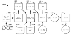
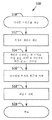
도 1a는 텔레시네에 사용하거나 또는 프린트하는데 적합한 필름으로 비디오를 아카이브하는 시스템을 도시한 도면;
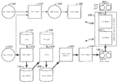
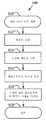
도 1b는 이전에 필름으로 아카이브된 비디오를 복구하는 시스템 및 아카이브로부터 필름 프린트를 생성하는 시스템을 도시한 도면;
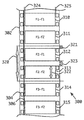
도 2는 필름으로 아카이브된 비디오의 순차 프레임의 시퀀스를 도시한 도면;
도 3은 필름으로 아카이브된 비디오의 필드 인터레이싱된 프레임의 시퀀스를 도시한 도면;
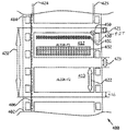
도 4a는 필름 상 순차 프레임 비디오 아카이브의 헤드에 사용하기 위한 특성화 패턴을 도시한 도면;
도 4b는 도 4a의 일부 확대도;
도 5는 비디오 데이터와 특성화 패턴에 대한 컬러 룩업 테이블(cLUT: color look-up table)을 사용하여 비디오의 필름 아카이브를 생성하는 공정을 도시한 도면;
도 6은 도 5의 공정에 의하여 생성된 필름 아카이브로부터 비디오를 복구하는 공정을 도시한 도면;
도 7은 비디오 데이터에 대해서만 cLUT를 사용하여 비디오의 필름 아카이브를 생성하는 공정을 도시한 도면;
도 8은 도 7의 공정에 의해 생성된 필름 아카이브로부터 비디오를 복구하는 공정을 도시한 도면;
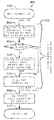
도 9는 필름 프린트를 제조하는데 적합한 필름 아카이브를 생성하는 방법에 사용하는 cLUT의 제1예를 생성하는 공정을 도시한 도면;
도 10은 필름 프린트를 제조하는데 적합한 필름 아카이브를 생성하는 방법에 사용하는데 적합한 cLUT의 다른 예를 생성하는 공정을 도시한 도면;
도 11은 예시적인 cLUT를 나타내는 그래프;
도 12a 내지 도 12b는 일부 필름 물질(film stocks)의 특성 곡선을 도시한 도면.The technique of the present invention will be more readily understood by considering the following detailed description with reference to the accompanying drawings.
1A illustrates a system for archiving video to film suitable for use in telecine or for printing;
FIG. 1B shows a system for restoring previously archived video to film and a system for generating film prints from an archive; FIG.
2 shows a sequence of sequential frames of video archived into film;
3 shows a sequence of field interlaced frames of video archived to film;
4A shows a characterization pattern for use in the head of a sequential frame video archive on film;
4B is an enlarged view of a portion of FIG. 4A;
FIG. 5 illustrates a process of generating a film archive of a video using a color look-up table (cLUT) for video data and characterization patterns; FIG.
FIG. 6 shows a process for recovering video from a film archive created by the process of FIG. 5; FIG.
FIG. 7 shows a process for creating a film archive of a video using cLUT only for video data; FIG.
8 shows a process for recovering video from a film archive created by the process of FIG.
FIG. 9 shows a process for creating a first example of a cLUT for use in a method of creating a film archive suitable for producing a film print; FIG.
FIG. 10 illustrates a process for creating another example of a cLUT suitable for use in a method of creating a film archive suitable for making a film print. FIG.
11 is a graph showing an example cLUT;
12A-12B show characteristic curves of some film stocks.
본 발명의 원리는 비디오 콘텐츠의 필름 아카이브를 생성하고 이 아카이브로부터 비디오 콘텐츠를 복구하는 방법 및 시스템을 제공한다. 비디오 데이터가 인코딩된 후에 비디오 데이터와 연관된 특성화 패턴과 함께 필름 상에 기록되어 원래의 비디오 데이터의 복구를 가능하게 한다. 비디오 데이터는 필름 아카이브로부터 생성된 텔레시네 또는 필름 프린트가 원래의 비디오 데이터의 복구가능성에 약간의 손상만으로 원래의 비디오에 더 잘 근접한 비디오 또는 필름 이미지를 생성할 수 있도록 인코딩된다. 예를 들어, 비디오 데이터의 적어도 일부에 대해 양자화 잡음이 증가할 수 있다. 일부 실시예에서, 비디오 데이터의 일부 부분에 대해서는 양자화 잡음이 감소하지만 전체적으로는 순수하게 증가할 수 있다. 필름이 현상(developed)될 때, 최종 필름은 텔레시네를 통해 판독되거나 사진 촬영으로 프린트될 수 있는 아카이브 품질 저장 매체를 제공한다. 아카이브가 복구를 위해 스캔될 때 특성화 패턴은 필름 프레임을 비디오로 디코딩하는 기초를 제공한다. 필름 프레임 스캔 데이터를 이후 디코딩하는 것은 필름 염료(film dyes)가 수 십년 퇴색된 경우에도 원래의 비디오와 유사한 비디오를 생성한다.The principles of the present invention provide a method and system for creating a film archive of video content and recovering video content from the archive. After the video data is encoded, it is recorded on the film with a characterization pattern associated with the video data to enable recovery of the original video data. Video data is encoded such that telecines or film prints generated from film archives can produce video or film images that are closer to the original video with only minor damage to the recoverability of the original video data. For example, quantization noise may increase for at least a portion of the video data. In some embodiments, the quantization noise is reduced for some portions of the video data but may increase purely overall. When the film is developed, the final film provides an archive quality storage medium that can be read through telecine or printed by photographing. Characterization patterns provide the basis for decoding film frames into video when the archive is scanned for recovery. Subsequent decoding of the film frame scan data produces a video similar to the original video even when film dyes have been faded for decades.
예를 들어, 키네스코프 또는 시네 카메라를 사용하여 모니터 상에 디스플레이되는 각 비디오 프레임의 화상을 취함으로써 필름 상에 기록된 화상으로 비디오 콘텐츠를 렌더링하는 종래 기술과는 달리, 본 발명의 아카이브 제작 시스템은 수치적 데이터로 비디오 신호를 처리하여 특성화 패턴을 사용하는 것에 의해 상당한 정밀도로 복구될 수 있다.Unlike the prior art, for example, using a kinescope or cine camera to take a picture of each video frame displayed on a monitor to render the video content into an image recorded on film, the archive production system of the present invention By processing the video signal with numerical data and using the characterization pattern, it can be recovered with considerable precision.
도 1a는 비디오 콘텐츠(108)와 특성화 패턴(110)을 포함하는 인코딩된 파일(114)을 제공하는 인코더(112), 인코딩된 파일을 기록하는 필름 레코더(116), 및 기록된 파일을 처리하여 비디오 콘텐츠의 필름 아카이브(126)를 생성하는 필름 프로세서(124)를 포함하는 본 발명의 필름 아카이브 시스템(100)의 일 실시예를 도시한다. 인코더(112)의 전체 활동과 연관하여 본 명세서에 사용된 바와 같이, "인코딩"이라는 용어는 비디오 데이터 포맷으로부터 필름 데이터 포맷으로, 예를 들어, 레코드 709 코드(Rec. 709 codes)(비디오 디스플레이 3원색의 비율 기여를 나타냄)로부터 필름 밀도 코드(필름 음화에서 3가지 염료의 각 밀도, 예를 들어, 0 내지 1023의 범위의 값을 가지는 시네온(Cineon) 코드를 나타냄)로 변환하고, (예를 들어, 비디오 데이터(108)와 특성화 패턴(110)에서 픽셀이 필름 레코더(116)의 이미지 공간에서 적절한 픽셀로 맵핑되므로) 공간적 및 시간적 포맷화를 포함한다. 이 문맥에서, 시간적 포맷화는 비디오 데이터의 시간 시퀀스에 따라 비디오로부터 필름 이미지 공간으로 픽셀을 맵핑하는 것을 말하며, 예를 들어 비디오의 연속적인 화상은 필름의 연속적인 프레임으로 맵핑된다. 순차 비디오에서 각 비디오 프레임은 단일 필름 프레임으로 기록되는 반면, 인터레이싱된 비디오는 별개의 필드, 예를 들어, 하나의 필드를 형성하는 픽셀의 홀수 행과 다른 필드를 형성하는 픽셀의 짝수행으로 기록되며, 프레임의 별개의 필드는 동일한 필름 프레임 내에 기록된다.1A illustrates an
원래의 비디오 콘텐츠(102)는 비디오 소스(104)를 통해 시스템(100)에 제공된다. 이 콘텐츠의 예로는 디지털 형태이든 아날로그 형태이든 비디오 테이프에 현재 저장된 텔레비전 쇼(shows)를 포함한다. 원래의 비디오 콘텐츠(102)의 포맷과 사용하기에 적합한 비디오 소스(104)(예를 들어, 비디오 테이프 플레이어)는 콘텐츠를 비디오 디지타이저(video digitizer)(106)에 제공하여 비디오 데이터(108)를 생성한다. 일 실시예에서, 비디오 데이터(108)는 이들이 다른 포맷에 비해 무시할 수 있는 결함을 초래하므로 RGB(적색, 녹색, 청색) 코드값이거나 이 코드값으로 변환가능하다. 비디오 데이터(108)가 비 RGB 포맷으로, 예를 들어 휘도값(luminance values)과 색차 값(chrominance values)으로 인코더(112)에 제공될 수 있으나, 이들 포맷을 사용하여 아카이브 및 비디오 변환 공정시 여러 불완전함과 혼선이 복구된 비디오에서 결함을 야기할 수 있다.The
비디오 데이터(108)는 수치 값을 사용하여 비디오 픽셀을 인코딩하는 규약(convention)을 제공하는 "레코드 709"와 같은 예를 들어 고선명 포맷(high-definition formats)을 포함하는 상이한 비디오 포맷으로 디지타이저(106)에 의해 제공될 수 있다. 레코드 709 표준(Recommendation BT.709, 스위스 제네바의 International Telecommunications Union, Radiocommunication Sector, 또는 ITU-R에 의해 간행됨)에 따라, 호환가능한 비디오 디스플레이는 2.4 멱 함수(power function)(또한 2.4의 감마를 가지는 것으로 언급됨)를 비디오 데이터에 적용하여 (예를 들어, 디지타이저(106)로부터) RGB 코드값(x)을 가지는 픽셀이 적절히 디스플레이될 때 x2.4에 비례하는 광 출력을 생성하게 한다. 다른 비디오 표준은 다른 멱 함수를 제공하며, 예를 들어, sRGB 표준과 호환되는 모니터는 2.2의 감마를 가진다. 소스로부터 오는 비디오 콘텐츠가 이미 디지털 형식, 예를 들어, 전문가 등급의 비디오 테이프 플레이어에 SDI 비디오 출력("Serial Digital Interface")로 제공되는 경우, 비디오 디지타이저(106)는 생략될 수 있다.
일부 구성에서, 원래의 비디오 콘텐츠(102)는 휘도값과 색차값으로, 즉 YCrCb 코드로 (또는 아날로그 표현으로, YPrPb로) 또는 RGB 코드값으로 변환가능한 다른 인코딩으로 표현될 수 있다. 나아가, 원래의 비디오 콘텐츠(102)는 예를 들어, 4:2:2로 서브샘플링되어(여기서, 각 4개의 픽셀에서 휘도 "Y"는 4개의 샘플로 표현되지만 색차 성분 "Cr" 및 "Cb"은 각각 2번만 샘플링된다), 이미지 품질에 상당한 영향을 미침이 없이 요구되는 대역폭을 1/3만큼 감소시킬 수 있다.In some configurations, the
콘텐츠의 비디오 데이터와 연관되고 도 4a 내지 도 4b와 연관하여 상세히 후술되는 특성화 패턴(110)이 인코더(112)에 제공되어 그 생성시에 아카이브의 공간적, 컬러메트릭적 및/또는 시간적 구성(또는 이들 구성 중 적어도 하나)을 수립하게 한다.
나아가, 컬러 룩업 테이블(cLUT)(128)이 인코더(112)에 제공되며 이 인코더는 특성화 패턴(110)과 cLUT(128)에 따라 비디오 데이터(108)를 인코딩한다. 비디오 데이터는 cLUT(128)를 사용하여 인코딩되거나 처리되며 cLUT는 디지털 비디오 코드를 필름 밀도 코드로 비디오 데이터를 변환하는 비선형 변환을 제공한다.Furthermore, a color lookup table (cLUT) 128 is provided to the
인코딩된 파일(114)은 도 5 및 도 7과 관련하여 후술되는 cLUT(128)로 처리 또는 인코딩되거나 되지 않을 수 있는 인코딩된 비디오 데이터와 특성화 패턴(110)을 포함한다. 필름 아카이브를 디코딩하는 디코더에 이용가능한 정보가 충분히 있는 한, 인코딩된 파일에 특성화 패턴의 일부만을 포함하는 것도 가능하다.Encoded
인코딩된 파일(114)에서, 특성화 패턴(110)은 예를 들어, 도 4a 내지 도 4b에서와 같이 인코딩된 비디오 데이터에 앞서 위치되거나 또는 인코딩된 비디오 데이터(미도시)와 동일한 필름 프레임으로 제공될 수 있다. cLUT 또는 보다 일반적으로 비선형 변환을 사용하는 것은 이 방법에서 상대적으로 고 품질의 필름 프린트를 만드는데 최적으로 적합한 필름 아카이브를 생성한다. 이 필름 프린트는 원하는 경우 필름 아카이브로부터 복구된 비디오 콘텐츠와 시각적으로 비교하기 위해 사영(projected)될 수 있다.In the encoded
인코더(112)에 의한 공간적 및 시간적 인코딩은 특성화 패턴(110)으로 제공되며 이 특성화 패턴은 비디오 정보의 각 프레임이 아카이브의 각 프레임에서 발견되는 곳을 나타낸다. 인터레이싱된 필드가 비디오 콘텐츠(102)에 존재하는 경우, 특성화 패턴(110)은 시간적으로 별개의 필드의 인코더(112)에 의해 수행되는 공간적 인코딩을 또한 나타낸다.Spatial and temporal encoding by the
이 정보는 패턴(110)에 포함된 데이터 또는 텍스트로 제공되거나, 또는 어느 것이 기계 또는 사람의 판독가능성에 적절한 것인 패턴의 공간적 구성이나 레이아웃에 기초한 것이다. 예를 들어, 패턴(110)은 이미지 데이터의 위치와 레이아웃에 관한 텍스트, 예를 들어, 말하자면 "이미지 데이터는 완전히 적색 경계 내에 및 밖에 있다"(예를 들어, 도 4b를 참조하면 요소(451))를 포함할 수 있고, 이 특정 정보는 아카이브 포맷과 친숙하지 않은 사람에게 특히 도움이 될 수 있다. 텍스트는 원래의 비디오의 포맷, 예를 들어, "1920×1080, 인터레이싱된, 60Hz"를 나타내는 주석을 패턴에 적용하는데 또한 사용될 수 있고, 각 프레임에 대해 시간 코드는 프린트될 수 있다(여기서, 교정 패턴의 적어도 일부는 아카이브를 통해 주기적으로 제공된다).This information is based on the spatial configuration or layout of the pattern, which is provided in the data or text contained in the
나아가, 특정 요소(예를 들어, 경계 또는 지시 라인)를 사용하여 데이터의 물리적 범위나 위치를 인코더(112)에 지시할 수 있으며, 프레임에서 2개의 데이터 영역에 대응하는 2개의 이러한 요소(또는 하나의 2배 높이 요소)의 존재는 프레임마다 인터레이싱되는 2개의 필드의 존재를 나타내는데 사용될 수 있다.In addition, certain elements (eg, boundaries or indicator lines) may be used to indicate to
다른 실시예에서 이진값(binary value)의 집합과 같은 데이터는 기하학적 기준 마크(reference mark)(기준 프레임과 수평 좌표와 수직 좌표에 대해 스케일을 나타냄)와 선택적으로 결합된 밝은 및 어두운 픽셀(light and dark pixel)로 제공될 수 있다. 이 수치에 기초한 위치와 스케일은 데이터 영역에 대해 그래프로 도시된 경계 대신에 사용될 수 있다. 이 이진 패턴은 각 프레임에 대해 적절한 SMPTE 시간 코드를 또한 나타낼 수 있다.In another embodiment, data, such as a set of binary values, is a light and dark pixel that is optionally combined with geometric reference marks (indicating scales for the reference frame and the horizontal and vertical coordinates). pixel). Positions and scales based on these values can be used instead of the graphically depicted boundaries for the data area. This binary pattern may also indicate an appropriate SMPTE time code for each frame.
인코더(112)에 의한 컬러메트릭적 인코딩에서, 특성화 패턴(110)은 선택된 코드값의 미리 결정된 공간적 배열을 형성하는 패치(patch)를 포함한다. 선택된 코드값(예를 들어, 비디오 백색, 흑색, 그레이색, 크로마 블루(chroma blue), 크로마 그린(chroma green), 여러 살색톤(flesh tone), 어스 톤(earth tone), 스카이색(sky blue) 및 다른 컬러)들이 이미지의 올바른 기술적 렌더링에 중요하거나, 사람의 인식에 중요하거나, 또는 폭넓은 컬러 범위를 예시하므로 선택될 수 있다. 각 미리 결정된 컬러는 미리 결정된 위치(예를 들어, 이 컬러가 패치 내에서 렌더링되는 위치)를 가져서 디코더가 이것이 있는 곳을 알 수 있게 한다. 이 패치에 사용되는 코드값은 각 컬러 성분에 대해 극단의 또는 극단 부근의 값을 포함하여 비디오 코드값의 전체 범위를 실질적으로 커버하도록 선택되어 특히 커버리지가 성긴(sparse) 경우에 적절한 정밀도로 비선택된 값의 내삽 또는 외삽을 가능하게 한다. 특성화 패턴이 cLUT를 사용하여 또한 인코딩된 경우, (아카이브된 비디오 콘텐츠에 대응하는) 비디오 코드의 전체 범위는 cLUT에 의해 인코딩되기 전에 패치로 표현될 수 있고, 예를 들어, 코드값은 비디오 코드의 실질적으로 전체 범위의 성긴 표현으로 선택된다. 특성화 패턴이 cLUT를 사용하여 인코딩되거나 처리되지 않은 경우에, 패치는 미리 결정된 밀도 값을 가져서 이로부터의 편차를 사용하여 (예를 들어, 에이징으로부터 또는 필름 처리시 변동으로부터) 아카이브에서 유동의 보상을 결정할 수 있다. 이렇게 결정된 보상은 역 cLUT와 연관하여 사용될 때 원래의 비디오 데이터 코드의 정확한 복구를 가능하게 한다. 특성화 패턴(110)에 공급된 패치의 서브세트는 그 값이 고정되거나 제로(0)인 다른 성분과 별개로 또는 독립적으로 컬러 성분을 제공하거나 및/또는 가변 조합(예를 들어, 모든 성분이 동일한 값을 가지는 그레이 스케일; 및/또는 비 그레이 값의 상이한 집합)으로 컬러 성분을 제공할 수 있다.In colormetric encoding by
성분을 별개로 제공하는 특성화 패턴(110)을 사용하는 것은 염료 혼선에 영향과 함께 아카이브가 에이징될 때 컬러 염료의 퇴색과 선형성의 용이한 특성화를 가능하게 한다. 그러나, 컬러 성분의 여러 조합을 가지는 패치는 유사한 정보를 전달하는데에도 사용될 수 있다. 특성화 패턴에서 컬러 패치의 코드값과 공간적 배열은 필름 아카이브로부터 비디오를 복구하는데 사용하기 위해 디코더에 이용가능하게 이루어진다. 예를 들어, 패치의 위치(기준 위치에 대해 상대적으로 또는 절대적으로) 및 그 컬러 또는 코드값 표현에 관한 정보는 디코더로 하여금 전체 처리 변동 또는 아카이브 에이징에 따른 문제에 개입함과 상관없이 패치를 적절히 해석할 수 있게 한다.Using the
비디오 디지타이저(106)가 RGB 또는 일부 다른 표현의 코드값을 생성하는지에 상관없이 비디오 데이터(108)는 RGB 코드값이거나 이로 변환될 수 있는 코드값을 포함한다. RGB 코드값은 일반적으로 10비트 표현이지만 이 표현은 더 작거나 더 클 수 있다(예를 들어, 8비트 또는 12비트).Regardless of whether
(예를 들어, 비디오 디지타이저(106)의 구성에 의해, 또는 RGB로 변환될 때 선택된 처리에 의해 결정되거나 또는 원래의 비디오 콘텐츠(102)나 비디오 소스(104)의 표현에 의해 미리 결정된) 비디오 데이터(108)의 RGB 코드의 범위는 특성화 패턴(110)으로 표현된 코드의 범위에 대응해야 한다. 다시 말해, 특성화 패턴은 바람직하게는 비디오 픽셀 값이 사용할 수 있는 코드의 범위를 적어도 커버하여 이 범위를 외삽할 필요성이 없다. (이 외삽은 매우 정확한 것일 것 같지 않다. 예를 들어, 패턴이 100 내지 900의 범위의 코드를 커버하지만, 비디오가 64 내지 940의 범위를 커버하는 경우, 비디오의 종단 서브 범위 64 내지 100 및 900 내지 940에서는 최근접한 2개 또는 3개의 이웃(neighbor)으로부터 외삽할 필요성이 있다(이는 예를 들어 매 100개의 카운트일 수 있다). 이 문제는 비디오 코드(64)에서의 필름 거동이 비디오 코드(100, 200) 등에 대응하는 방식과 유사한 방식으로 광에 대응하는 것을 가정하여 비디오 코드(100, 200, 300 등)에 대한 변환에 기초하여 비디오 코드(64)에 대한 변환을 추정하는 것으로부터 발생하며, 그러나 이러한 가정은 필름의 특성 곡선이 일반적으로 로우(low) 및 하이(high) 노출 한계 부근에서는 비선형 응답을 가지기 때문에 사실상 그렇지 않다.Video data (e.g., determined by the configuration of the
예를 들어, 특성화 패턴(110)이 10비트 코드값을 사용하고 및 비디오 데이터(108)에 대한 코딩이 단 8비트인 경우, 인코더(112)에 의한 인코딩 동작의 일부로서 비디오 데이터(108)는 좌로 이동되고 제로(0)가 패딩되어 10비트 값을 생성할 수 있는데, 여기서 8개의 최상위 비트는 원래의 8비트 값에 대응한다. 다른 예에서, 특성화 패턴(110)이 비디오 데이터(108)의 표현보다 더 적은 수의 비트를 사용하는 경우, 비디오 데이터(108)의 남는 최하위 비트는 (라운딩을 하거나 또는 라운딩 없이) 절삭되어 특성화 패턴 표현의 사이즈와 매칭될 수 있다.For example, if the
패턴의 특정 구현이나 설계에 따라, cLUT(128)로 인코딩된 특성화 패턴(110)을 인코딩된 파일(114)에 포함하는 것은 아카이브에 대한 에이지의 효과를 포함하여 아카이브를 해석하는데 자체 문서화 또는 충분한 자체 정보를 제공할 수 있다. 예를 들어, 에이지의 효과는 특성화 패턴에서 요소들이 아카이브에서 비디오 이미지와 동일한 에이징 효과를 가질 수 있으므로 비디오 데이터에 대한 코드값의 전체 범위를 나타내는 밀도 그래디언트와 같은 컬러메트릭적 요소에 기초하여 고려될 수 있다. 컬러 패턴이 비디오 콘텐츠에 대한 전체 컬러 범위를 나타내는 것으로 설계된 경우, 디코더가 패턴에 관한 사전 지식 또는 미리 결정된 정보를 가짐이 없이 알고리즘적으로 또는 학습적으로 패턴을 디코딩하는 것이 또한 가능하다. 다른 실시예에서, 아카이브 해석을 위한 텍스트 명령은 특성화 패턴에 포함될 수 있으며 이에 따라 디코더는 패턴에 관한 사전 지식 없이 아카이브를 디코딩할 수 있다.Depending on the particular implementation or design of the pattern, the inclusion of the
특성화 패턴(110)이 cLUT(128)로 인코딩되지 않은 (그러나, 대신, 디지털 픽셀 값과 필름 밀도 코드 사이에 선형 변환을 사용하거나 밀도 변환을 사용하여 인코딩된) 실시예에서, 아카이브에 대한 에이지의 효과는 특성화 패턴에 밀도 그래디언트를 사용하는 것에 의해 고려되지만 원래의 cLUT(128)나 그 역(도 1b에서 요소(148))의 형태의 추가적인 문서 또는 지식이 아카이브 해석에 필요할 수 있다.In embodiments where the
메모리 디바이스(미도시)에 저장되었는지 및 차후에 인코더(112)가 동작할 때 실시간으로 호출되거나 스트리밍되었는지에 상관없이 인코딩된 파일(114)은 필름 레코더(116)에 제공되고, 이 필름 레코더는 인코딩된 파일 데이터에 따라 컬러 필름 물질(118)을 노출시켜 잠재 아카이브 데이터를 가지는 필름 출력(122)(즉, 노출된 필름)을 생성하고 이는 화학적 필름 프로세서(124)에서 현상되고 고착되어 필름 아카이브(126)를 생성한다.The encoded
필름 레코더(116)의 목적은 인코딩된 파일(114)에서 각 픽셀에 대한 밀도 코드값을 수용하고 필름 물질(118)에 노출을 생성하여 필름 프로세서(124)에 의해 처리된 특정 컬러 필름 밀도를 필름 아카이브(126)에 초래하는 것이다. 필름 레코더(116)에 제공되는 코드값과 필름 아카이브 상의 최종 밀도 사이에 관계 또는 상관성을 개선시키기 위하여 필름 레코더(116)는 교정 절차로부터 데이터(120)를 사용하여 교정된다. 필름 밀도 코드를 필름 밀도로 변환하는 룩업 테이블에 제공될 수 있는 교정 데이터(120)는 필름 물질(118)의 특정 제조 및 필름 프로세서(124)의 예상되는 설정에 따라 좌우된다. 필름 물질(118)이 그 특성 곡선에서 임의의 비선형성, 즉 log10 노출(lux-sec 단위로)과 밀도(투과율의 역수의 log10인 밀도) 사이의 관계를 가지는 정도까지, 교정 데이터(120)는 선형화를 생성하여 밀도 코드값의 주어진 변화로 밀도 코드값의 전체 범위에 걸쳐 밀도의 고정된 변화를 생성한다. 나아가, 교정 데이터는 염료 감도에서 혼선을 위한 보상 매트릭스를 포함할 수 있다.The purpose of the
일 실시예에서, 필름 물질(118)은 중간 필름 물질(예를 들어, Eastman Color Internegative II Film 5272, 뉴욕주의 로체스터시에 소재한 Kodak사 제품), 특히 필름 레코더에 사용하도록 설계된 것(예를 들어, Kodak VISION3 Color Digital Intermediate Film 5254, Kodak사 제품)이고, 더 선형인 특성 곡선을 가지도록 설계된다. 도 12a는 특정 노출 및 처리 조건에서 청색, 녹색 및 적색 컬러에 대해 이 필름의 특성 곡선을 도시한다.In one embodiment, the
다른 유형의 필름 물질이 상이한 대응하는 교정 데이터(120)에 사용될 수 있다. 도 12b는 도 12a의 것에 비해 더 짧은 선형 영역, 즉 선형 영역(BC) 내에서 더 작은 범위의 노출 값을 나타낼 수 있는 이들 물질의 특성 곡선(예를 들어, 하나의 컬러에 대한)의 다른 예를 도시한다. 나아가, 특성 곡선은, 낮은 노출에서, 즉 증분 노출(incremental exposure)이 선형 영역(BC)에 비해 상대적으로 작은 증분 밀도를 생성하는 곡선에서 더 작은 슬로프에서 감소된 필름 감도를 가지는 보다 상당한 (예를 들어, 더 큰 범위의 노출에 걸쳐) "발가락(toe)" 영역(AB)을 구비하며, 더 높은 노출에서 노출의 함수로서 유사하게 감소된 필름 감도를 가지는 "어깨"(shoulder) 영역(CD)을 구비한다. 이들 물질에서, 전체 특성 곡선은 보다 명확한 S자 형상을 가진다. 그럼에도 불구하고, 대응하는 교정 데이터(120)는 필름 아카이브에 기록되는 픽셀 코드값과 밀도 사이에 관계를 선형화하는데 사용될 수 있다. 그러나, 최종 필름 아카이브(126)는 필름 프로세서(124)와 필름 레코더(116)의 정밀도의 변동에 보다 민감하다. 나아가, 이 특성 곡선의 선형 영역(BC)은 코닥 매개 음화 II 필름 5272(Kodak Internegative II Film 5272)의 것보다 더 가파르므로, 즉 밀도의 변동이 노출 시 주어진 증분 변화에 더 크므로, 이 물질은 이 중간 영역의 잡음에 보다 더 취약하다(그리고 낮거나 높은 노출 영역에서는 덜 그렇다).Other types of film materials may be used for different
따라서, 필름 아카이브를 생성하기 위하여 (예를 들어, 픽셀의 컬러의 적색 원색의 양에 대응하는) 인코딩된 파일(114)로부터 수치적 밀도 코드값 'c'이 교정 데이터(120)에 기초한 대응하는 필름 기반 파라미터, 예를 들어, (종종 "상태-M"이라고 언급되는 유닛으로 측정된) 필름 밀도로 변환하기 위해 필름 레코더(116)에 제공된다. 교정은 밀도 코드값 'c'과 최종 밀도 사이의 정밀한 미리 결정된 선형 관계를 제공한다. 하나의 일반적으로 사용되는 예에서, 필름 레코더는 증분 코드값마다 0.002의 증분 밀도를 제공하도록 교정된다. 원하는 필름 밀도를 생성하는데 필요한 노출은 필름 특성 곡선(도 12a 및 도 12b와 유사한)으로부터 결정되고 필름 물질에 적용되어 필름 프로세서(124)에 의해 처리된 후의 필름 아카이브를 생성한다. 필름 아카이브로부터 비디오 콘텐츠를 검색하기 위해, 필름 밀도는 도 1b의 아카이브 검색 시스템에서 후술되는 바와 같이 교정되는 필름 스캐너에 의해 코드값 'c'로 다시 변환된다.Thus, the numerical density code value 'c' from the encoded file 114 (e.g., corresponding to the amount of red primary color of the color of the pixel) to produce a film archive corresponds to the corresponding correction based on the
도 1b는 필름 아카이브, 예를 들어 아카이브 제작 시스템(100)에 의해 생성된 필름 아카이브(126)로부터 비디오를 복구하는 아카이브 판독 또는 검색 시스템(130)의 일례를 도시한다. 필름 아카이브(126)는 최근에 필름 아카이브 시스템(100)에 의해 이루어진 것이거나 상당히 에이징된 것일 수 있다(즉, 아카이브 판독 시스템(130)은 아카이브 생성 50년 후에 아카이브(126)에 동작할 수 있다). 비디오 데이터는 디지털 비디오로부터 비선형 변환에 기초하여, 예를 들어 cLUT를 사용하여 필름 밀도 코드로 변환되므로, 본 발명의 필름 아카이브는 (비디오 데이터와 필름 밀도 코드 사이에 선형 변환을 사용하는 다른 아카이브에 비해) 개선된 품질을 가져서 필름 프린트 출력 시스템(160)에 의해 아카이브로부터 생성된 필름 프린트는 사영이나 디스플레이를 하는데 충분히 적합한 품질을 제공한다.FIG. 1B shows an example of an archive reading or
필름 아카이브(126)는 필름 스캐너(132)에 의해 스캔되어 필름 밀도를 밀도 코드값으로 표현된 필름 데이터(136)로 변환한다. 필름 스캐너(132)는 교정 데이터(120)와 유사하게 필름 밀도에 대해 스캐너의 응답을 선형화하고 정규화하는 파라미터 값(예를 들어, 오프셋, 비선형일 수 있는 스케일링, 혹 자기 자신의 컬러 룩업 테이블)의 집합인 교정 데이터(134)를 가진다. 교정된 스캐너를 가지고, 필름 아카이브(126) 상의 밀도가 측정되고 필름 데이터(136)에 선형 코드값을 생성하며, 즉 증분 코드값은 필름 아카이브(126)에서 적어도 밀도 범위 전체에 걸쳐 동일한 밀도 변화를 나타낸다. 다른 실시예에서, 교정 데이터(134)는 필름 스캐너(132)에 의해 측정가능한 밀도 범위 전체에 걸쳐 밀도 코드를 선형화할 수 있다. 적절히 교정된 스캐너로 (예를 들어, 밀도 코드값과 필름 밀도 사이에 선형 관계를 가지고), 인코딩된 파일(114)로부터 코드값 'C'에 대응하는 밀도로 기록된 이미지 부분은 스캐너(132)로 판독되거나 측정되고, 에이징 효과 또는 처리 유동을 제외하고 최종 수치적 밀도 코드값이 정확치는 않지만 대략 'C'와 같다.The
공간적 및 시간적 디코딩를 위한 파라미터를 수립하기 위해, 디코더(138)는 필름 데이터(136)를 판독하고 조사하여 특성화 패턴(110)에 대응하는 부분을 발견하며 이는 데이터 영역의 위치, 즉 필름 데이터(136) 내 비디오 데이터(108)의 표현을 포함하는 영역을 식별하기 위해 더 조사된다. 이 조사는 비디오 데이터(108)가 순차 래스터를 포함하는지 또는 인터레이싱된 래스터를 포함하는지 여부를 나타내며 여기서 프레임이나 필드에 대응하는 데이터 영역이 발견된다.To establish parameters for spatial and temporal decoding,
필름 아카이브의 컬러메트리를 디코딩하기 위하여, 즉 필름 밀도나 필름 밀도 코드를 디지털 비디오 코드로 변환하기 위하여, 컬러메트릭 룩업 테이블이 특성화 패턴(110)으로부터 오는 정보에 기초하여 디코더에 의하여 수립될 수 있다. 특성화 패턴이 아카이브로 원래 인코딩된 방식에 따라(즉, 비디오 데이터와 동일한 cLUT를 사용하여 인코딩되었는지 여부에 따라), 이 룩업 테이블은 필름 아카이브에서 이미지 데이터를 디코딩하는 정보 또는 변환을 획득하는데 사용될 수 있다.In order to decode the colormetry of the film archive, ie convert film density or film density code to digital video code, a color metric lookup table can be established by the decoder based on the information coming from the
아카이브에서 특성화 패턴이 cLUT(128)를 사용하여 인코딩된 경우, 디코더(138)는 (특성화 패턴에 관한 또는 특성화 패턴으로부터 획득된 사전 지식이나 정보에 기초하여) 필름 데이터(136)에서 어느 밀도 코드값이 특성화 패턴(110)에서 원래의 픽셀 코드에 대응하는지 및 컬러메트릭 룩업 테이블이 디코더(138) 내에서 생성되는지를 인식한다. 예를 들어, 패턴에 관한 사전 지식은 미리 결정되거나 디코더에 별도로 제공될 수 있고 또는 정보는 명시적이거나 규약상 알려진 패턴 그 자체에 포함될 수 있다. 성길 수 있는 이 룩업 테이블은 특히 필름 데이터(136)를 디코딩하는데 사용하기 위해 생성된다. 이후 비디오 콘텐츠 데이터에 대응하는 필름 데이터(136)의 부분에서 판독된 밀도 코드값이 디코딩되는데, 즉 필요에 따라 내삽에 의한 것을 포함하여 이 룩업 테이블을 사용하여 비디오 데이터로 변환될 수 있다. 특성화 패턴은 디코더가 디코딩 활동의 일부로서 역 cLUT를 구성하는데 충분한 정보를 포함하기 때문에, 외부적으로 제공된 역 cLUT(148)는 이 실시예에서 아카이브를 디코딩하는데 필요치 않다. 이것은 원래의 특성화 패턴(110)으로 표현된 비디오 코드값 각각에 대해 필름 아카이브(126)로부터 복구된 필름 데이터(136)에 매립된 특성화 패턴이 대응하는 실제 필름 밀도 값을 이제 포함하기 때문이다. 미리 결정된 비디오 데이터 값과 및 대응하는 관측된 필름 밀도 값의 집합은 이들 값에서는 정확한 역 cLUT이고 이들 값은 내부적으로 구성된 역 cLUT로 표현되지 않은 값을 처리하기 위해 내삽될 수 있다. 이 디코딩 접근법은 도 6과 관련하여 더 설명되고 도시된다.If the characterization pattern in the archive has been encoded using
아카이브에서 특성화 패턴(110)이 cLUT(128)를 사용하여 인코딩되지 않았다면, 디코더(138)는 필름 데이터(136)에서 어느 밀도 코드값이 (다시, 패턴에 관한 사전 지식 또는 패턴으로부터 획득된 정보에 기초하여) 특성화 패턴(110)의 원래의 픽셀 코드에 대응하는지를 인식하고, 성길 수 있는 룩업 테이블이 디코더(138) 내에 생성된다. 이 룩업 테이블은 역 cLUT(148)를 통해 곱셈되어 비디오 데이터(108)에 대응하는 필름 데이터(136)의 부분에 특히 적합한 디코딩 변환을 생성한다. 이후, 필름 데이터(136)의 부분에서 대응하는 비디오 데이터(108)의 밀도 코드값이 디코딩되는데, 즉 필요에 따라 내삽에 의한 것을 포함하여 디코딩 변환을 사용하여 비디오 데이터 포맷으로 변환될 수 있다. 이 디코딩 절차는 1) 아카이브의 에이징 효과가 패턴에 기초하여 생성된 룩업 테이블을 사용하여 필름 밀도 코드값을 변환하는 것에 의해 고려되는 것, 및 2) 역 cLUT가 "디에이징된"(de-aged)(즉, 에이징 효과가 제거된) 밀도 코드값을 비디오 코드값으로 변환하는 것으로 이해될 수 있다.If the
이 실시예에서, (비디오 데이터를 인코딩하는데 사용되는 cLUT(128)의 역인) 역 cLUT(148)는 원래의 비디오 데이터를 복구하는데 필요하다. 이 디코딩 접근법은 도 8 및 도 11과 관련하여 더 도시되고 설명된다.In this embodiment, an inverse cLUT 148 (inverse of the
따라서, 비디오 데이터는 적절한 경우 필드마다인지 또는 프레임마다인지에 상관없이 필름 데이터(136)로부터 디코더(138)에 의해 추출되고 컬러메트릭적으로 디코딩된다. 복구된 비디오 데이터(140)는 비디오 출력 디바이스(142)에 의해 판독되고 이 디바이스는 비디오 데이터(140)를 비디오 레코더(144)에 적절한 비디오 신호로 포맷하여 재생성된 비디오 콘텐츠(146)를 생성할 수 있다.Thus, video data is extracted and colormetrically decoded from the
비디오 레코더(144)는 예를 들어, 비디오 테이프 또는 디지털 비디오 디스크 레코더일 수 있다. 대안적으로, 비디오 레코더(144) 대신에, 방송 또는 콘텐츠 스트리밍 시스템이 사용될 수 있고, 복구된 비디오 데이터(140)가 중간 기록된 형태 없이 디스플레이를 위해 직접 제공될 수 있다.
아카이브 제조 및 아카이브 판독 시스템(100, 130)에 대해 품질 체크 또는 유효성의 입증으로 원래의 비디오 콘텐츠(102)와 및 재생성된 비디오 콘텐츠(146)가 비디오 비교 시스템(150)에서 조사될 수 있고 이 시스템은 디스플레이(152, 154)를 포함하여 오퍼레이터로 하여금 원래의 비디오와 및 복구된 비디오를 나란히 표현하여 볼 수 있게 한다. 비교 시스템(150)의 다른 실시예에서, A/B 스위치는 공통 디스플레이 상에 하나의 비디오와 다른 비디오를 교번하며 보여줄 수 있다. 또 다른 실시예에서, 2개의 비디오는 동일한 디스플레이 상에 원래의 비디오의 하나의 절반을 제공하고 복구된 비디오의 동일한 절반의 미러 이미지를 제공하는 "버터플라이(butterfly)" 디스플레이로 보여질 수 있다. 이 디스플레이는 2개의 비디오의 대응하는 부분들이 유사한 환경(예를 들어, 각 배경에 대해 유사한 콘트라스트를 가짐)으로 제공되어 2개의 비디오 사이에 시각적 비교를 용이하게 하므로 듀얼(예를 들어, 나란히) 디스플레이하는 것에 비해 이점을 제공한다. 본 발명에 따른 필름 아카이브로부터 생성된 비디오 콘텐츠(146)는 원래의 비디오 콘텐츠(102)의 것과 실질적으로 동일하다.The
추가적으로, 필름 프린트 출력 시스템(160)은 필름 아카이브(126)를 특정 필름 프린트 물질(162)을 사용하여 잘 조절된 필름 프린터(164)(별도로 도시되지 않은 개발 프로세서를 포함함)로 공급하여 필름 프린트(166)를 생성하며 이 필름 프린트는 사영 시스템(168)을 사용하여 사영된다. 필름 프린트(166)의 사영이 원래의 비디오 콘텐츠(102) 또는 재생성된 비디오 콘텐츠(146)의 디스플레이와 함께 보여질 때, 오퍼레이터는, 필름 아카이브(126)도 필름 프린트(166)도 실질적으로 에이징되지 않은 한, 2개의 표현에 상당한 매칭이 있는 것(즉, 필름 컬러의 재타이밍이 비디오 디스플레이(152/154)와 매칭하는데 필요치 않을 수 있다)을 발견하게 된다.Additionally, film
도 2 및 도 3은 필름 아카이브(126) 내에서 인코딩된 비디오 데이터의 프레임의 예시적인 실시예를 도시한다. 필름 아카이브(200)에서, 여러 순차 스캔 비디오 프레임은 필름 상에 프레임(F1, F2 및 F3)으로 인코딩되고, 필름 아카이브(300)에 있는 인터레이싱된 스캔 비디오 프레임은 F1-f1, F2-f2 등과 같은 분리된 연속적인 필드로 인코딩되고 여기서 F1-f1 및 F2-f2는 동일한 프레임(F1) 내 서로 다른 필드(f1, f2)를 나타낸다. 필름 아카이브(200, 300)는 예시적인 필름 프레임(220, 320)의 각 위치와 간격을 수립하는 204와 304와 같은 대응하는 천공(perforation)을 가지는 필름 물질(202, 302) 위에 각각 저장되거나 기록된다. 각 필름 아카이브는 아날로그 또는 디지털 또는 이들 둘 모두일 수 있는 선택적 사운드트랙(206, 306) 또는 개별적으로 아카이브된 오디오 트랙과 동기화된 시간 코드 트랙(미도시)을 구비할 수 있다.2 and 3 show exemplary embodiments of frames of video data encoded within
필름 아카이브(200)의 데이터 영역(210, 211, 212)과 필름 아카이브(300)의 데이터 영역(310, 311, 312, 313, 314, 315)은 그 대응하는 필름 프레임(프레임(220, 320)은 예시적인 것임) 내에 이격된 각 비디오 필드의 표현을 포함한다. 이들 데이터 영역은 대응하는 필름 프레임의 에지로부터 수평 간격(224, 225, 324, 325), 대응하는 필름 프레임의 시작부터 수직 간격(221, 321), 수직 높이(222, 322) 및 필드간 분리 거리(323)를 가지는 인터페이싱된 필드를 구비한다. 이들 파라미터 또는 차원은 특성화 패턴에 제공된 공간적 및 시간적 기술에 의해 모두 식별되고 도 4a 및 도 4b와 관련하여 상세히 후술된다.The
도 4a는 이 예에서 인터레이싱된 필드를 가지는 원래의 비디오 콘텐츠(102)에 대해 필름 아카이브(126) 내 헤더(400)로 기록된 특성화 패턴(110)을 도시한다. 필름 프레임 높이(420)는 종래의 4-천공("4-천공") 필름 프레임을 형성하는 4개의 천공(천공(404)으로 도시됨)의 연속과 동일한 길이이다. 대안적인 실시예에서, 상이한 정수개의 필름 천공이 필름 프레임 높이로 선택될 수 있다.4A shows the
도시된 실시예에서, 각 4-천공 필름 프레임에서, 데이터 영역(412, 413)은 2개의 비디오 필드(예를 들어, 필름 아카이브(300)에서 필드(312, 313)와 유사함)의 표현을 포함하며, 각 경계에 의해 한정될 수 있다. 이 예에서, 데이터 영역의 각 경계는 데이터 영역(412)의 경계를 형성하는 직사각형(451, 452, 453)의 코어 부분에 대응하는 영역(450)의 확대도를 도시하는 도 4b에 보다 상세히 도시된 바와 같이 3개의 직사각형으로 표시된다. 다시 말해, 코너 영역(450)을 구비하는 도 4a에서의 직사각형은 픽셀로 필름(400) 위에 그려진 3개의 직사각형(451, 452, 453)을 포함하며, 예를 들어 각 직사각형은 하나의 픽셀 두께이다. 직사각형(452)은 인접한 직사각형(451, 453)으로부터 컬러 및/또는 필름 밀도가 상이하며, 해쉬 패턴(hash pattern)으로 도시된다. 이 예에서, 필드(412)를 위한 데이터 영역은 직사각형(452) 상에 또는 내에 위치된 픽셀(즉, 직사각형(453)의 것을 포함하는 직사각형(452) 내부 영역(412))을 포함하지만, 직사각형(451) 안의 것 또는 외부 것을 배제한다. 직사각형(451)은 데이터 대(versus) 비 데이터 영역 사이 경계의 검출을 용이하게 하기 위해 용이하게 인식가능한 컬러, 예를 들어, 적색으로 제공될 수 있다.In the illustrated embodiment, in each four-perforated film frame,
따라서, 필름 아카이브(300)의 각 데이터-포함 프레임에서, 영역(412, 413)이 특성화 패턴 프레임(420) 내에 (경계 직사각형(452)에 이르는 것을 포함하여) 배치된 것과 정확히 동일하게 제1 및 제2 필드(예를 들어, F2-f1 및 F2-f2)가 대응하는 필름 프레임(예를 들어, 프레임(320))에 배치된다. 이 실시예에서, 필름 레코더(116)와 필름 스캐너(132)는 정확하고 반복적으로 필름 물질(118)과 필름 아카이브(126)를 각각 위치시켜 인코딩된 파일(114)을 필름 아카이브로 및 비디오 복구 동안에는 필름 아카이브로부터 필름 데이터(136)로 재생가능하고 정확히 맵핑하는 것을 보장하는데 필요하다.Thus, in each data-bearing frame of the
따라서, 스캐너(132)에 의해 판독될 때, 직사각형(451 내지 453)은 각 필름 프레임에서 제1 필드의 위치 또는 경계를 정확히 지정한다. 필름 레코더 및 필름 스캐너는 서브 픽셀 정밀도로 천공에 대해 필름을 위치시킬 수 있는 원리로 동작한다. 따라서, 필름(300)의 4개의 천공(304)에 대해, 각 제1 필드(예를 들어, F1-f1, F2-f2 및 F3-f1)는 다른 홀수 필드와 같이 그 프레임의 4개의 천공에 동일한 공간적 관계를 구비하며 이는 제2 필드(F1-f2, F2-f2 및 F3-f2)에 대해서도 그러하다. 이 동일한 공간적 관계는 제1 필드와 제2 필드가 위치된 영역을 한정하는 특성화 패턴(400)에 대해서도 그러하다. 따라서, (직사각형(451, 452, 453)과 같은) 특정 경계 구성으로 표현된 영역(412)은 제1 필드(F1-f1, F2-f1 및 F3-f1 등)의 위치를 지정한다.Thus, when read by
유사하게, 데이터 영역(413) 주위에 직사각형은 각 제2 필드(예를 들어, F1-f2, F2-f2 및 F3-f2)가 발견되는 곳을 지정할 수 있다. 순차 스캔 실시예에서, 대응하는 경계(예를 들어, 도 4b에 상술된 것과 유사한 직사각형)를 가지는 단일 데이터 영역은 순차 프레임 비디오 데이터 영역(예를 들어, 210 내지 212)가 후속 필름 프레임(예를 들어, 220)에서 발견될 수 있는 곳을 지정할 수 있다.Similarly, a rectangle around
제1 필드(412)의 상부(412T)는 도 4a 및 도 4b에 도시되고 헤드 갭(421)을 한정한다. 사이드 갭(424, 425) 및 영역(413) 아래 테일 갭(tail gap)(426)을 따라, 상부 갭(421)이 데이터 영역(412, 413)이 필름 프레임(420) 내에 충분히 끼워지는 것을 보장하여 필름 레코더(116)가 기록할 전체 데이터 영역(412, 413)을 신뢰성있게 어드레스할 수 있도록 선택되고, 필름 스캐너(132)는 판독할 전체 데이터 영역에 신뢰성있게 액세스할 수 있다. 필드 인터레이싱된 비디오 콘텐츠의 아카이브에서 (제1 및 제2 필드(412, 413)에 비해 과장된 비율로 도시된) 필드간 갭(423)의 존재는 스캐너에서 필름의 오정렬로부터 발생할 수 있는 스캔된 이미지에 상당한 에러를 도입함이 없이 각 필드가 정밀하고 별개로 저장되고 복구될 수 있는 것을 보장한다. 다른 실시예에서, 2개의 필드가 서로 접하는 것인 필드간 갭(423), 즉 효과적으로 제로(0)인 갭이 없는 것이 가능하다. 그러나, 필드간 갭(423) 없이, 스캐너에서 오정렬은 하나의 필드의 에지 부근 픽셀이 인접한 필드의 픽셀로 판독되거나 스캔되는 것을 초래할 수 있다.Top 412T of
필름 프레임(420)에서 특성화 패턴은 예를 들어, 컬러메트릭적 요소(430 내지 432)를 포함한다. 컬러메트릭적 요소는, 일례에서 컬러 염료 각각에서 최소로부터 최대로 (예를 들어, 이 밀도가 새로운 필름 아카이브(126) 내 필름 물질(118)로부터 달성가능하다고 가정하면 약 0.15의 단차(step)로 약 0.05의 밀도로부터 3.05의 밀도로) 밀도 범위를 커버하는 21-단계 그레이스케일인 천연 그래디언트(neutral gradient)(430)를 포함할 수 있다. 전술된 바와 같이, 밀도 그래디언트는 에이징 효과를 위한 자가 교정 툴로 사용될 수 있다. 예를 들어, 그래디언트(430)의 밝은 단부(즉, 최소 밀도)가 미래에 언젠가 스캔될 때 10% 더 조밀한 것으로 발견되면, 디코더(138)는 대응하는 양만큼 아카이브 필름에서 가장 밝거나 가장 낮은 밀도를 감소시키는 것에 의해 이 에이징 효과를 보정할 수 있다. 그래디언트의 어두운 단부(즉, 최대 밀도)가 5% 덜 조밀하다면, 아카이브 필름에서 유사한 어두운 픽셀은 대응하는 양만큼 증가될 수 있다. 나아가, 임의의 밀도 값에 대한 선형 내삽은 그래디언트로부터 2개의 판독값에 기초하여 이루어질 수 있고, 그래디언트(430)에 걸쳐 추가적인 판독값을 사용하는 것에 의해 시스템은 비선형 에이징 효과를 보상할 수 있다.The characterization pattern in the
컬러메트릭적 요소는, 일례에서 제1 최소 밀도로부터 실질적으로 단 하나의 염료(제1 컬러를 측정하기 위한) 또는 2개의 염료(제2 컬러를 측정하기 위한)의 최대 밀도로 21-단계 스케일인 하나 이상의 제1 또는 제2 컬러 그래디언트(431)를 더 포함할 수 있다. 천연 밀도 그래디언트에 대해 전술된 것과 유사하게, 각 염료의 에이징으로부터 발생하는 밀도 유동이 더 측정되고 보상이 제공될 수 있다.The colormetric element is, in one example, 21-step scale from the first minimum density to a maximum density of substantially only one dye (to measure the first color) or two dyes (to measure the second color). One or more first or
보다 완전한 특성화를 위해, 컬러메트릭적 요소는 특정 컬러를 나타내는 패치(432)의 집합을 포함할 수 있다. 예시적인 컬러의 집합은 컬러 전달 및 조절을 위한 ANSI IT8 표준, 예를 들어, 스캐너를 교정하는데 통상 사용되는 워싱턴 DC 소재 어메리칸 내셔널 표준 인스티튜트사(American National Standards Institute, Washington, DC)에서 발행한, 입력 스캐너 교정을 위한 IT8.7/1 R2003 그래픽 테크놀로지사의 컬러 전달 타겟(Graphic Technology - Color Transmission Target); 또는 미시간주의 그랜드 래피즈시에 소재한 X-Rite 사에서 시판하는 문셀 컬러체커(Munsell ColorChecker)에서 발견되는 것과 일반적으로 유사할 수 있다. 이 컬러는 컬러 색 영역(color gamut)의 보다 자연적인 부분을 강조하여 그레이스케일이나 순수한 제1 또는 제2 컬러보다 살색 톤과 나뭇잎을 더 잘 나타내는 컬러 샘플을 제공한다.For more complete characterization, the color metric element may include a set of
특성화 패턴은 단일 필름 프레임(420)의 헤더에 제공될 수 있다. 대안적인 실시예에서, 프레임(420)의 특성화 패턴은 다수의 판독값과 적절한 필터링에 기초하여 (예를 들어, 필름 기록, 처리 또는 스캔에 영향을 미치는 먼지 얼룩으로부터) 잡음이 거부될 수 있다는 이점과 함께 여러 추가적인 프레임 각각에서 동일하게 재생될 수 있다. 다른 실시예에서, 특성화 패턴은 예를 들어, 더 많은 특성화 정보(예를 들어, 추가적인 컬러 패치 또는 단차진 그래디언트)를 제공하기 위해 필름 프레임(420)에 더하여 다수의 필름 프레임(미도시)에 걸친 헤더에 제공될 수 있다. 예를 들어, 특성화 패턴은 다수의 필름 프레임에 걸쳐 제공된 상이한 테스트 패턴, 예를 들어, 그레이스케일을 테스트하기 위해 제1 프레임에 있는 테스트 패턴, 각 컬러를 테스트하기 위해 3개의 프레임에 있는 3개의 상이한 테스트 패턴(예를 들어, 각각 적색, 녹색 및 청색)의 시퀀스를 포함할 수 있고, 테스트 패턴을 가지는 4개 더 많은 프레임은 유용한 나뭇잎과 피부색 팔레트(skin tone palettes)를 커버한다. 이 특성화 패턴은 8개의 프레임에 걸쳐 연장하는 것으로 또는 대안적으로 8개의 프레임에 제공된 상이한 특성화 패턴으로 고려될 수 있다.The characterization pattern may be provided in the header of the
도 5는 필름 상에 프린트가능한 비디오 아카이브를 생성하는 공정(500)의 일례를 도시한다. 도 1a의 것과 같은 필름 아카이브 시스템에 의해 구현될 수 있는 공정(500)은 단계(510)에서 시작하고, 여기서 디지털 비디오 데이터(108)는 인코더(112)에 제공된다(또는 인코더에 의해 수용된다). 단계(512)에서, 비디오 데이터와 연관된 대응하는 특성화 패턴(110)이 또한 제공된다. 인코더와 호환가능한(및 또한 비디오를 복구하는 디코더와 호환가능한) 포맷을 가지는 특성화 패턴이 비디오 데이터와 관련된 정보를 가지는 텍스트 파일로 또는 비디오 프레임에 포함되는 이미지(들)로 제공될 수 있다. 이 포함은 (특성화 패턴을 가지는 리더(leader)를 형성하는) 헤더로 미리 계류 중인 것에 의해 수행되거나 또는 이미지 데이터의 하나 이상의 프레임과 복합물로 또는 이에 포함될 수 있으나, 프레임 내 갭 영역과 같은 이미지 데이터를 포함하지 않는 판독가능한/기록가능한 영역에 포함될 수 있다. 특성화 패턴은 다음 사항, 즉 특히 비디오 포맷, 비디오 프레임을 위한 시간 코드, 데이터 영역의 위치, 컬러 또는 밀도 값, 필름 아카이브 에이징, 필름 레코더 및/또는 스캐너의 비선형 또는 왜곡 중 하나 이상에 관한 정보를 운반하도록 설계된 하나 이상의 요소를 포함한다.5 shows an example of a
단계(514)에서, 비디오 데이터(108)(예를 들어, 레코드 709 포맷)와 특성화 패턴(110)의 모든 픽셀 값이 cLUT(128)를 사용하여 인코딩되어 (그 생성은 도 9 및 도 10과 관련하여 후술됨) 각 픽셀 값에 대응하는 밀도 코드값인 인코딩된 데이터(114)를 생성한다. 특성화 패턴에 의해 설명된 레이아웃에 따라 특성화 패턴과 비디오 데이터 픽셀은 인코딩된 데이터(114)의 하나 이상의 프레임에 존재하거나 공동 존재(co-resident)하거나 또는 패턴과 비디오 데이터 픽셀은 (예를 들어, 헤더로 패턴을 미리 계류하는 경우에서와 같이) 별개의 프레임을 차지할 수 있다.In step 514, all pixel values of video data 108 (e.g., record 709 format) and
cLUT를 사용하여 특성화 패턴이나 비디오 데이터의 픽셀 값을 인코딩하는 것은 패턴이나 비디오의 데이터가 비선형 변환에 기초하여 대응하는 밀도 코드값으로 변환되는 것을 의미한다. 도 11의 곡선(1130)은 비디오 코드값과 밀도 코드값 사이에 비선형 맵핑이나 상관을 제공하는 cLUT의 일례이다. 이 예에서, 특성화 패턴에서 여러 요소, 예를 들어, 자연 그래디언트(430), 제1 또는 제2 컬러 그래디언트(431) 또는 특정 컬러 패치(432)로부터 원래의 픽셀 코드가 곡선(1130) 상의 실제 데이터 점(도트)에 의해 표현된다.Encoding pixel values of a characterization pattern or video data using a cLUT means that the data of the pattern or video is converted to the corresponding density code value based on the nonlinear transformation.
단계(516)에서, 인코딩된 데이터(114)는 필름 레코더(116)에 의하여 필름 물질(118)로 기록된다. 레코더가 밀도 코드값(예를 들어, 시네온 코드값)과 필름 밀도 값 사이에 선형 관계에 기초하여 교정된 후에, 잠재 이미지가 각 밀도 코드값에 따라 적절한 노출에 의해 필름 음화 상에 형성된다. 단계(518)에서, 노출된 필름 물질이 알려지거나 종래의 기술을 사용하여 처리되거나 현상되어 단계(520)에서 필름 아카이브(126)를 생성한다.In
프린트가능한 필름 아카이브(126)는 사용되는 cLUT(128)에 따라 필름에 프린트되거나 또는 텔레시네를 통해 비디오로 직접 변환될 수 있다. cLUT(128)는 특정 필름 물질로 프린트하거나, 또는 특정 교정을 가지는 텔레시네에 사용하도록 최적화될 수 있다. 상이한 필름 물질에 프린트하거나 또는 상이하게 교정된 텔레시네에서 사용하는 것은 예측가능하게 더 낮은 충실도 결과를 가진다. cLUT의 목적은 원래의 비디오 레코드 709 코드값을 타깃 응용에 직접 사용하는데 최상으로 적합한 필름 밀도 값 세트로 맵핑하여 원래의 레코드 709 코드값의 복구를 허용하는 것이 여전히 가능하다.The
도 6은 아카이브 생성 공정(500)에 의해 이루어진 프린트가능한 필름 아카이브(에이징된 아카이브일 수 있음)로부터 비디오 콘텐츠를 복구하는 공정(600)의 일례를 도시한다.6 illustrates an example of a
단계(610)에서, 필름 아카이브, 예를 들어, 도 1a로부터 아카이브(126)는 필름 스캐너에 제공되고, 이 필름 스캐너는 필름 아카이브 상의 밀도를 판독하고 이를 시네온 코드와 같은 대응하는 필름 밀도 코드값으로 변환하는 것에 의해 필름 데이터(136)를 생성한다. 특정 아카이브 및 특성화 패턴에 따라, 전체 필름 아카이브를 스캔하거나 판독하는 것이 필요치 않으나, 대신 적어도 하나 이상의 데이터 영역, 즉 비디오 콘텐츠에 대응하는 데이터를 포함하는 부분을 스캔하거나 판독하는 것이 필요하다. 예를 들어, 특성화 패턴이 비디오 데이터에 관한 공간적 및 시간적 정보만을 포함(컬러메트릭적 정보 없이)하는 경우, 특성화 패턴 그 자체를 스캔을 하는 일 없이 올바른 비디오 데이터 부분을 식별하는 것이 가능할 수 있다. (필름 레코더와 유사하게, 스캐너는 밀도 코드값과 필름 밀도 값 사이에 선형 관계에 기초하여 또한 교정된다.)In
단계(614)에서, 특성화 패턴에 관한 사전 지식에 기초하여, 디코더(138)는 필름 데이터(136)로부터 특성화 패턴(110)의 기록을 픽업하거나 식별한다. 단계(616)에서, 디코더(138)는 특성화 패턴 및/또는 여러 요소(예를 들어, 백색에서 시작하여 10개의 선형 단계에서 진행하는 그레이스케일 그래디언트에 대응하는 특정 패치 또는 특정 컬러 정렬 세트를 나타내는 특정 패치)의 구성에 관한 다른 사전 지식을 사용하여 데이터 영역의 위치와 타이밍 및/또는 컬러메트리에 대한 사양을 포함하는 필름 데이터(136)에 적절한 정보를 디코딩할 것을 결정한다. 전술된 바와 같이, 이 실시예에서 특성화 패턴은 비디오 데이터에 대한 것과 동일한 cLUT를 사용하여 인코딩되므로, 이 특성화 패턴은 디코더가 디코딩 활동의 일부로서 역 cLUT를 획득하거나 구성하는 데 충분한 정보를 포함한다. 단계(618)에서, 디코더(138)는 단계(616)로부터 디코딩 정보를 사용하여 비디오 데이터를 포함하는 아카이브(126) 내 데이터 영역을 디코딩하고, 필름 밀도 코드값을 변환하여 비디오 데이터를 생성한다. 공정(600)은 비디오가 비디오 데이터로부터 복구되는 단계(620)에서 완료된다.In
도 7은 필름 상에 프린트가능한 비디오 아카이브를 생성하는 다른 공정(700)을 도시한다. 단계(710)에서, 디지털 비디오 데이터(108)는 인코더에 제공되거나 이에 의해 수신된다. 단계(712)에서 비디오 데이터(108)의 각 픽셀의 값은 cLUT(128)를 사용하여 인코딩되고, 즉 비디오 데이터는 디지털 비디오 포맷(예를 들어, 레코드 709 코드값)으로부터 밀도 코드값과 같은 필름 기반 포맷으로 변환된다. 다시, 도 11의 곡선(1130)은 cLUT의 일례이다.7 shows another process 700 for creating a printable video archive on a film. In
단계(714)에서, 대응하는 특성화 패턴(110), 즉 비디오 데이터와 연관된 패턴은 또한 인코더에 제공된다. 인코딩된 데이터(114)는 cLUT를 사용하여 인코딩된 비디오 데이터와 cLUT(128)를 사용하여 인코딩되지 않은 특성화 패턴을 포함한다. 대신, 특성화 패턴은 패턴의 컬러 패치의 비디오 코드값을 밀도 코드값으로 변환하는 선형 맵핑과 같은 미리 결정된 관계를 사용하여 인코딩된다.In step 714, the corresponding
일 실시예에서, 패턴의 데이터는 레코드 709 코드값으로부터 도 11에서 라인(1120)으로 표현된 선형 함수에 기초하여 밀도 코드값으로 변환하는 것에 의해 인코딩된다(이 예시적인 경우에, 라인(1120)은 1의 슬로프를 구비하여 레코드 709 코드값이 밀도 코드값과 정확히 동일하다).In one embodiment, the data of the pattern is encoded by converting from record 709 code values to density code values based on a linear function represented by
전술된 바와 같이, 특성화 패턴과 비디오 데이터는 상이한 프레임에서 (예를 들어, 도 4에서와 같이) 별개로 제공될 수 있거나 특성화 패턴은 예를 들어 비-이미지 데이터 영역에서 (프레임 내 갭(323)에서와 같이) 이미지 데이터를 또한 포함하는 프레임에 포함될 수 있다.As described above, the characterization pattern and the video data may be provided separately in different frames (eg, as in FIG. 4) or the characterization pattern may be provided in the non-image data area (eg,
단계(716)에서, 인코딩된 데이터(114)는 필름 레코더(116)로 필름 물질(118)에 기록되고, 필름 물질은 단계(178)에서 처리되어 필름 아카이브(126)를 생성한다. 프린트가능한 아카이브 생성 공정(700)은 단계(720)에서 완료된다. 이 실시예에서, 특성화 패턴은 단계(712)에서 cLUT(128)로 인코딩되지 않는다.In
공정(500)의 생산물과 같이, 공정(700)으로부터 아카이브(126)는 필름에 프린트될 수 있거나 텔레시네를 통해 비디오로 직접 변환되어 유사한 결과를 제공할 수 있다.Like the product of
도 8은 아카이브 생성 공정(700)에 의해 이루어진 프린트가능한 필름 아카이브(126)로부터 비디오를 복구하는 공정(800)을 도시한다. 단계(810)에서, 프린트가능한 필름 아카이브(126)(예를 들어, "에이징"된 아카이브일 수 있음)는 도 1b의 필름 스캐너(132)와 같은 스캐너에 제공된다. 단계(812)에서, 필름 데이터(136)는 필름 밀도로부터 밀도 코드값으로 스캔된 판독값을 변환하는 것에 의해 생성된다. 단계(814)에서, 특성화 패턴에 관한 사전 지식에 기초하여, 디코더(138)는 필름 데이터(136)로부터 특성화 패턴을 픽업하거나 식별한다. 단계(816)에서, 특성화 패턴, 및/또는 이 패턴에서 여러 요소에 관한 사전 지식은 필름 데이터(136)에 적절한 정보를 디코딩할 것을 결정하는데 사용된다. 디코딩 정보는 데이터 영역의 위치와 타이밍, 정규화된 컬러메트리에 대한 사양, 및 이 컬러메트리 사양을 완료하기 위해 역 cLUT(148)(필름 아카이브 생성 동안 비디오 데이터를 인코딩하는데 사용되는 cLUT의 역)을 포함한다. 단계(818)에서, 디코더(138)는 단계(816)로부터 디코딩 정보를 사용하여 비디오 데이터를 포함하는 아카이브(126) 내 데이터 영역을 디코딩하고 필름 밀도 코드로부터 변환하여 비디오 데이터를 생성한다. 이 비디오는 단계(820)에서 비디오 데이터로부터 복구된다.8 shows a
도 7 및 도 8의 이 인코딩-디코딩 방법(비디오 데이터만이 도 11의 곡선(1130)과 같은 cLUT로 인코딩되고, 패턴은 도 11의 라인(1120)과 같은 선형 변환에 기초하여 인코딩됨)은 필름의 전체 밀도 범위가 에이지로 이동되거나 유동되는 방식을 특성화하는 반면, 도 5 내지 도 6의 방법(비디오 데이터와 특성화 패턴은 cLUT를 사용하여 인코딩된다)은 이미지 데이터를 인코딩하는데 사용되는 필름 밀도 값의 서브 범위가 유동된 방식 및 역 cLUT를 구현하는 방식을 특성화하여, 디코딩할 때 역 cLUT가 별개로 요구되거나 적응되지 않는다. 도 7 내지 도 8의 방법에서, 도 11의 곡선(1130)에서 dlow, dhigh 및 dmid의 위치는 역 룩업을 위해 비디오 데이터를 인코딩하는데 사용된 원래의 cLUT를 유지함이 없이 특성화 패턴으로부터 결정될 수 없다.This encoding-decoding method of FIGS. 7 and 8 (only video data is encoded with a cLUT such as
상기 공정의 다른 변동은 인코딩 목적으로 사용되고 인코딩된 파일에 제공된다 하더라도 필름 아카이브로부터 특성화 패턴 또는 그 일부를 생략하는 것을 포함할 수 있다. 이 경우에, 추가적인 정보는 디코더가 필름 아카이브를 적절히 디코딩하는데 필요할 수 있다. 예를 들어, 이미지의 위치와 밀도가 표준으로 미리 규정되는 경우, 필름 아카이브에 특성화 패턴을 포함할 필요가 없다. 대신, 표준 또는 다른 규약의 사전 지식이 디코딩시에 사용하기 위한 추가적인 정보를 제공한다. 특성화 패턴을 스캔할 것을 요구하지 않는 이 상황 및 다른 상황에서, 공정(600)과 공정(800)에 있는 단계(614)와 단계(814)는 생략될 수 있다. 다른 예는 필름 아카이브에서 패턴, 예를 들어, 컬러 패치의 일부만을 포함하는 것을 수반할 수 있다. 패치를 해석하는 추가적인 정보는 아카이브를 디코딩하는데 필름 아카이브와는 별도로 디코더에 이용가능하게 이루어질 수 있다.Other variations of the process may include omitting characterization patterns or portions thereof from the film archive, even if used for encoding purposes and provided in the encoded file. In this case, additional information may be needed for the decoder to properly decode the film archive. For example, if the location and density of an image is predefined as a standard, it is not necessary to include a characterization pattern in the film archive. Instead, prior knowledge of the standard or other protocol provides additional information for use in decoding. In this and other situations that do not require scanning of the characterization pattern, steps 614 and 814 in
본 발명의 필름 아카이브를 생성하는데 사용하기 위한 cLUT를 생성하는 방법을 설명하기 전에, cLUT에 관한 추가적인 상세 및 배경이 후술된다. cLUT를 사용하는 것은 컴퓨터 그래픽 및 이미지 처리분야에서 알려져 있다. cLUT는 제1 픽셀 값(소스)으로부터 제2 픽셀 값(목적지)으로 맵핑을 제공한다. 일례에서, cLUT는 레코드 709 코드값의 스칼라 값을 밀도 코드의 스칼라 값으로 맵핑한다(예를 들어, 도 11에서 라인(1130), 레코드 709 코드는 픽셀의 적색, 녹색, 또는 청색 중 하나의 것과 같은 단일 컬러 성분만을 나타낸다). 단일 값 LUT은 혼선이 없거나 장래에 무시할 수 있는 시스템에 적절하다. 이 cLUT는 1차원 매트릭스로 표현될 수 있으며 이 경우에 각 원색(적색, 녹색, 청색)이 각각 처리되고 예를 들어 10의 적색 값을 가지는 소스 픽셀은 소스 픽셀의 녹색과 청색 값에 상관없이 20의 적색 값을 가지는 목적지 픽셀로 변환될 수 있다.Before describing a method of generating a cLUT for use in creating a film archive of the present invention, further details and background regarding the cLUT are described below. The use of cLUT is known in the field of computer graphics and image processing. The cLUT provides a mapping from the first pixel value (source) to the second pixel value (destination). In one example, the cLUT maps the scalar value of the record 709 code value to the scalar value of the density code (e.g.,
다른 예에서, cLUT는 소스 값을 나타내는 픽셀의 컬러 트리플릿(color triplet)(예를 들어, R, G, B에 대한 3개의 레코드 709 코드값)을 밀도 코드의 대응하는 트리플릿으로 맵핑한다. 이 표현은 (예를 들어, 녹색 민감 염료가 적색 광에도 약간 민감한 경우 또는 현상될 때 녹색 민감 염료가 녹색 광과는 다른 광은 흡수를 하지 않을 때 초래될 수 있는 적색 민감 및 녹색 민감 필름 염료들 사이에 혼선으로 인해) 3개의 컬러 축이 실제 직교하지 않을 때 적절하다.In another example, the cLUT maps a color triplet of pixels representing the source value (eg, three record 709 code values for R, G, and B) to the corresponding triplet of density codes. This expression refers to red sensitive and green sensitive film dyes that may result, for example, when the green sensitive dye is slightly sensitive to red light or when developed, when the green sensitive dye does not absorb light other than green light. This is appropriate when the three color axes are not really orthogonal (due to crosstalk between them).
이 cLUT는 3차원(3D) 매트릭스로 표현될 수 있으며, 이 경우에 3개의 원색이 목적지 픽셀로 변환되는 소스 컬러 큐브(color cube)에서 3D 좌표로 처리된다. 3D cLUT에서, 소스 픽셀에서 각 원색의 값은 목적지 픽셀에서 이 원색들 중 어느 하나 또는 전부에 영향을 미치거나 또는 그 어느 것에도 영향을 미치지 않을 수 있다. 예를 들어, 10의 적색 값을 가지는 소스 픽셀은 녹색 및/또는 청색 성분의 값에 따라 20, 0, 50 등의 적색 값을 가지는 목적지 픽셀로 변환될 수 있다.This cLUT can be represented as a three-dimensional (3D) matrix, in which case the three primary colors are processed as 3D coordinates in the source color cube, where the three primary colors are converted into destination pixels. In a 3D cLUT, the value of each primary color in the source pixel may or may not affect any or all of these primary colors in the destination pixel. For example, a source pixel having a red value of 10 may be converted into a destination pixel having a red value of 20, 0, 50, etc. according to values of green and / or blue components.
종종, 특히, 각 컬러 성분(예를 들어, 10 이상)을 나타내는 다수의 비트를 가지는 시스템에서 cLUT는 성길 수 있으며, 즉 단지 몇 개의 값만이 LUT에 제공되고, 다른 값은 필요에 따라 그 사용시에 보간된다. 이것은 메모리와 액세스 시간을 절감한다. 예를 들어, 10비트 원색 값을 가지는 조밀한 3D cLUT는 각 가능한 소스 픽셀 값에 대한 맵핑을 제공하는데 (2^10)^3(여기서 2^10은 2의 10 제곱(power)을 나타냄)을 요구하거나 또는 10억개를 약간 더 초과하는 엔트리를 요구한다. 잘 거동하는, 즉 극단적인 곡률도 없고 불연속성도 없는 cLUT에서, 성긴 cLUT가 생성될 수 있고 목적지 픽셀에 대한 값은 관련 소스 픽셀로부터 대응하는 소스 픽셀의 상대적 거리에 기초하여 최근접한 이웃(nearest neighbor)(또는 최근접한 이웃과 그 이웃)을 할당하는 것을 수반하는 잘 알려진 방법에 의해 보간된다. 레코드 709 값에 대한 성긴 cLUT에 대한 종종 합리적인 밀도는 17^3이고, 즉 컬러 큐브의 각 축을 따라 각 컬러 원색에 대한 17개의 값이며, 이는 cLUT에서 5000개보다 약간 미만의 목적지 픽셀 엔트리를 초래한다.Often, especially in systems with multiple bits representing each color component (e.g., 10 or more), the cLUT may be sparse, ie only a few values are provided to the LUT, while other values are used at that time as needed. Interpolated. This saves memory and access time. For example, a dense 3D cLUT with 10-bit primary color values provides a mapping for each possible source pixel value, where 2 ^ 10 represents 3 power of 10. Demands, or slightly more than 1 billion entries. In a cLUT that behaves well, i.e. without extreme curvature and no discontinuity, a coarse cLUT can be generated and the value for the destination pixel is the nearest neighbor based on the relative distance of the corresponding source pixel from the associated source pixel. Interpolated by well-known methods involving assigning (or the nearest neighbor and its neighbors). Often a reasonable density for a sparse cLUT for record 709 values is 17 ^ 3, i.e. 17 values for each color primary along each axis of the color cube, resulting in fewer than 5000 destination pixel entries in the cLUT. .
도 9는 본 발명에서 사용하기 위한 적절한 cLUT, 예를 들어, 도 1a에 있는 cLUT(128)를 생성하는 공정(900)을 도시한다. 이 예의 의도는 필름 레코더(116)에서 음화 물질(118)을 노출하는데 적합한 필름 밀도 코드값으로 비디오 코드값을 변환하는 cLUT를 생성하여, 최종 필름 아카이브(126)가 필름 프린트(166)를 제조하는데 최적으로 적합하여, 사영 시스템(168)과 디스플레이(152, 154)로부터의 출력을 조사하는 오퍼레이터가 상당한 매치를 인식할 수 있게 하는 것이다.9 illustrates a
공정(900)은 시작(910)에서 시작하며, 여기서 원래 비디오 코드 공간, 이 예에서 레코드 709는 장면과 관련된(scene-referred) 것으로 특정된다.
단계(911)에서, 비디오 데이터는 원래의 컬러 공간(예를 들어, 레코드 709)으로부터 1931 CIE 색도도(chromaticity diagram)의 좌표계인 XYZ와 같은 관찰자와 관련된(observer-referred) 컬러 공간으로 변환된다. 이것은 레코드 709 코드값에 지수(exponent)(예를 들어, 텔레비전 시청에 사용되는 일반적인 거실이나 침실을 나타내는 것으로 고려된 "딤 서라운드"(dim surround) 시청 환경에 적절한 감마 값으로 2.35 또는 2.4)를 적용하여 수행된다. 관찰자와 관련된 컬러 공간으로 변환을 하는 이유는 cLUT의 목적이 관찰자에 제공될 때 가능한 한 근접하여 비디오와 같이 보이게 필름을 제조하는 것이기 때문이다. 이것은 기준 점으로 관찰자를 처리하는 컬러 공간에서 가장 편리하게 달성된다(그리하여, "관찰자와 관련된"이라고 언급된다).In
이 기술 분야에 통상의 지식을 가진 자에게 알려진 "장면과 관련된(scene-referred)" 또는 "출력과 관련된(output-referred)"이라는 용어는 주어진 컬러 공간에서 실제로 코드값이 한정하는 것이 무엇인지를 나타내는데 사용된다. 레코드 709의 경우에 "장면과 관련된"이란 카메라에 비춰 교정 카드(특별히 프린트되는, 구체적으로 그 위에 있는 컬러 매트 패치를 가지는 교정 보드의 물리적 시트)에서 반사되는 광의 양에 구체적으로 관한 장면에 있는 어떤 것과 관련된다는 것을 의미한다(카드의 백색은 코드값(940)이고, 카드의 흑색은 코드값(64)이고, 특정 그레이 패치가 더 한정되어 지수 곡선에 대한 파라미터를 설정한다). "출력과 관련된"이란 코드값이 모니터 또는 사영 스크린 상에 특정 양의 광을 생성하는 것을 의미한다. 예를 들어, 얼마나 많은 풋-람베르트(foot-Lamberts of light)의 광이 코드에 대해 스크린에서 방출되어야 한다. 레코드 709는 무슨 컬러 원색이 사용되어야 하는지 및 무슨 컬러가 백색에 대응하는지를 지정하여서 표준에서 "출력과 관련된" 일부 장면이 있으나, 코드값에 대한 키 정의는 "장면과 관련"된다.) "관찰자와 관련된"이란 사람이 광과 컬러를 인식하는 정도와 관련된다. XYZ 컬러 공간은 사람이 컬러를 인식하는 정도의 측정값에 기초하고 시스템이 이미지를 캡처하거나 디스플레이하는데 사용하는 원색 컬러와 같은 것에 의해 영향을 받지 않는다. XYZ 공간에서 한정된 컬러는 이것이 생산되는 방식에 상관없이 동일한 것을 볼 수 있다. 따라서, 동일한 XYZ 값에 대응하는 2개의 표현(예를 들어, 필름과 비디오)이 동일한 것을 볼 수 있다. 1931 CIE 데이터로부터 또는 약간 변경된 특정 상세를 가지는 보다 현대적인 개선예로부터 모두 유도된 관찰자와 관련된 다른 컬러 공간, 예를 들어, Yuv, Yxy 등이 있다.The terms "scene-referred" or "output-referred", known to those skilled in the art, indicate what the code values actually limit in a given color space. Used to indicate. In the case of record 709, "scene related" means any scene in the scene that specifically relates to the amount of light reflected from the calibration card (the physical sheet of the calibration board with a specially printed color matte patch on it). (The white of the card is the
단계(912)에서, 최종 색 영역, 즉 관찰자와 관련된 컬러 공간(XYZ1로 식별된)으로 변환한 후 이미지 데이터의 색 영역이 필름으로 표현가능한 것을 상당히 초과하는지 여부("상당히"를 구성할 수 있는 것은 특히 필름 색 영역이 초과할 수 있는 정도와 지속기간에 관한 것일 수 있는 정책적인 사항이다)에 대해 체크 또는 질문이 이루어진다. 필름 색 영역이 상당히 초과하지 않는다고 결정되면, 관찰자와 관련된 코드(색 영역 XYZ1에서)가 단계(914)로 전달된다. 필름 색 영역은 필름 매체로 표현될 수 있는 모든 컬러의 위치를 말한다. 필름 색 영역은 필름으로 표현될 수 없는 컬러가 언급될 때 "초과"된다. 필름 색 영역이 일부 곳에서 비디오의 것(예를 들어, 포화된 시안, 황색, 마젠타)을 초과하고, 비디오의 색 영역이 다른 곳에서 필름의 것(예를 들어, 포화된 적색, 녹색 및 청색)을 초과한다.In
그렇지 않고, 단계(912)에서 XYZ1에서 색 영역이 필름 프린트(166)의 것을 상당히 초과할 수 있다는 우려가 있다면, 색 영역은 단계(913)에서 재맵핑되어 재형성된 색 영역(여전히 XYZ 컬러 공간에서, 그러나 이제 XYZ2로 식별된)에서 코드를 생성한다. 색 영역이 컬러 공간이 아니라 컬러 공간에서의 값의 위치인 것이 주목된다. 필름의 색 영역은 필름으로 표현가능한 모든 가능한 컬러이고, 비디오의 색 영역은 비디오로 표현가능한 모든 가능한 컬러이며, 특정 비디오 데이터의 색 영역(예를 들어, 비디오 데이터(108))은 전체 비디오 데이터에 실제 사용되는 고유한 컬러의 집합이다. 이를 XYZ 컬러 공간으로 표현하는 것에 의해, 그렇지 않은 다른 이미지의 색 영역(필름은 흡수성 매체이고, 비디오 디스플레이는 방출성이다)이 비교될 수 있다.Otherwise, if there is a concern that the color gamut at XYZ 1 may significantly exceed that of the
색 영역 재맵핑을 위한 기술은 수많이 알려져 있고, 대부분 성공적인 것은 색 영역의 상이한 영역에서 상이한 기술로부터 결과를 조합한 하이브리드이다. 일반적으로 색 영역 재맵핑은 인식적으로 균일한 컬러 공간(관찰자와 관련된 컬러 공간의 특별한 서브세트)에서 최상으로 수행되며, CIE 1976(L*, a*, b*) 컬러 공간(CIELAB)이 특히 잘 적합하다. 따라서, 색 영역 재맵핑 단계(913)의 일 실시예에서, XYZ1 색 영역에서 코드는 레코드 709 백색점(발광체)을 사용하여 CIELAB로 변환되고, 그 결과 코드는 실질적으로 필름 색 영역을 초과하지 않게 재맵핑된 후에 XYZ 컬러 공간으로 다시 재변환되어 수정된 색 영역(XYZ2)을 생성하며, 이는 이제 이용가능한 필름 색 영역을 상당히 초과하지 않는 특성을 가진다.Many techniques for color gamut remapping are known and most successful are hybrids that combine results from different techniques in different regions of the color gamut. In general, color gamut remapping is best performed in a perceptually uniform color space (a special subset of the color space associated with the observer), with the CIE 1976 (L *, a *, b *) color space (CIELAB) especially Well suited. Thus, in one embodiment of color
XYZ 컬러 공간보다 CIELAB의 색 영역을 재맵핑하는 가치나 이점은 특정 스케일의 특정 컬러에 이루어진 변화가 색 영역에서 다른 곳, 즉 다른 컬러에 동일한 스케일의 변화가 이루어진 것 같이 변화된 인식 정도가 유사하다(이는 인식적으로 균일하므로 CIELAB의 특성이다)는 것이다. 다시 말해, CIELAB 공간에서, 임의의 방향으로 컬러 공간에서 임의의 축을 따라 특정 양만큼 동일한 변화가 사람에 의해 "동일한 사이즈"의 변화로 인식된다. 이것은 컬러가 색 영역의 일부 영역에서 일 방향으로 수정되고 색 영역의 다른 영역에서 다른 방향(또는 전부는 아닌)으로 수정될 때 불일치 또는 초과 결함을 생성하지 않는 색 영역 재맵핑을 제공하는 것을 도와준다. (비디오 디스플레이가 필름 색 영역과는 다른 컬러 색 영역을 가지므로, 필름 색 영역에 없는 비디오 색 영역의 특정 컬러가 있을 수 있다. 따라서, 비디오 색 영역에서 밝은 포화된 녹색이 필름 색 영역에서 찾을 수 없는 경우 이 녹색 컬러는 XYZ 공간에서 (일반적으로 말해서) 마이너스-y 방향으로 이를 이동시키는 것에 의해 재맵핑될 수 있다. 이것은 특정 녹색이 덜 포화되게 하는 경향이 있는 (XYZ 공간에 대해 CIE 차트의 백색 영역을 향해 "백색 쪽"을 이동시키는) 효과를 제공한다. 그러나, 색 영역에서 녹색이 연 녹색으로 재맵핑되므로, 원래의 비디오 색 영역에서 다른 녹색 컬러가 또한 유사한 방향으로 다른 양만큼 이동되거나 수정되어 색 영역에서 다소 국부적인 효과를 유지할 필요가 있다.)The value or advantage of remapping the color gamut of CIELAB over the XYZ color space is that the degree of perception is changed, as changes made in a particular color of a particular scale are changed elsewhere in the color gamut, i.e. This is a characteristic of CIELAB since it is cognitively uniform). In other words, in CIELAB space, the same change by a certain amount along any axis in the color space in any direction is perceived by the person as a change of "same size". This helps to provide color gamut remapping that does not create inconsistencies or excess defects when colors are modified in one direction in some areas of the gamut and in other directions (or not all) in other areas of the gamut. . (Since the video display has a different color gamut than the film gamut, there may be certain colors in the video gamut that are not in the film gamut. Therefore, bright saturated green in the video gamut may be found in the film gamut. If absent, this green color can be remapped by moving it in the minus-y direction (typically speaking) in the XYZ space, which is the white of the CIE chart for the XYZ space that tends to make certain greens less saturated. Effect, which shifts the "white side" toward the area, but because green is remapped to light green in the color gamut, other green colors in the original video color gamut are also shifted or corrected by a different amount in a similar direction. To maintain a somewhat local effect in the color gamut.)
예를 들어, 특정 포화된 녹색이 비디오 데이터(108)에서 요구되지만, 이들이 필름 프린트(166)에 의해 재현가능한 색 영역 밖에 있는 경우, 비디오 데이터(108)에서 이들 포화된 녹색은 재맵핑 단계(913) 동안 덜 포화 및/또는 덜 밝게 만들어질 수 있다. 그러나, 이용가능한 필름 색 영역을 초과하지 않을 수 있는 다른 근접 값에서 재맵핑은 재맵핑되어야 하는 값과 중복을 피할 필요가 있다. 나아가, 중복을 단지 피하는 것 이상으로 가시적 결함(예를 들어, Mach bands)의 가능성을 최소화하기 위하여 (인식 컬러 공간에서) 가능한 한 평활하게 재맵핑을 하는 노력이 이루어져야 한다.For example, if certain saturated greens are required in the
단계(914)에서, 자연 색 영역(XYZ1) 또는 재맵핑된 색 영역(XYZ2)에서의 코드는 역 필름 프린트 에뮬레이션(iFPE)을 통해 처리된다. iFPE는 다른 cLUT가 (다른 이유로 그리고 다른 경험에 기초하여) 형성되는 것과 같이 함수 또는 함수를 표현하는 cLUT로 표현될 수 있다. 이 경우에, iFPE를 표현하는 cLUT는 XYZ 컬러 값을 필름 밀도 코드로 변환하며 3D cLUT로 구현될 수 있다. 필름 프린트 에뮬레이션(FPE: film print emulation)은 필름 물질(118, 162)을 특성화하는 것이며 필름 레코더(116)에 제공되었을 수 있는 밀도 값 세트(예를 들어, 시네온 코드)를 사영 시스템(168)을 시청할 때 측정될 것으로 예상되는 컬러 값으로 변환하는 사영 시스템(168)의 발광체(사영 램프 및 반사기 광학기기)를 특성화하는 것이다. FPE는 이들이 디지털 모니터로부터 동작시키는 오퍼레이터로 하여금 샷(shot)에 컬러 보정을 하게 하고 디지털 및 필름 기반 영화의 배급 시 올바르게 보는 보정을 기대하게 하므로 동화상 산업에서 디지털 중간 제작 작업에 잘 알려져 있다.In
상기 성긴 cLUT의 설명에서와 같이, FPE는 우수한 결과를 제공하는 17×17×17 성긴 cLUT로 적절히 표현될 수 있다. 이것은 FPE를 역변환하여 iFPE를 생성하는 (이 기술 분야에 통상의 지식 내에서) 수리적으로 간단한 수학적 연산이다. 그러나, 많은 경우에, 17×17×17 cLUT의 역은 적절한 평활화 특성 및/또는 잘 한정된 경계 효과를 제공하지 않을 수 있다. 이 경우에 역변환될 FPE는 덜 성긴 매트릭스, 예를 들어, 34×34×34로 모델링되거나 또는 더 높은 변화율을 나타내는 영역에서 더 조밀한 샘플링을 가지는 비균일한 매트릭스를 사용하여 모델링될 수 있다.As in the description of the coarse cLUT, the FPE may be appropriately expressed as a 17 × 17 × 17 coarse cLUT which gives good results. This is a mathematically simple mathematical operation (within common knowledge in the art) to invert FPE to produce iFPE. In many cases, however, the inverse of the 17 × 17 × 17 cLUT may not provide adequate smoothing properties and / or well defined boundary effects. In this case the FPE to be inversely transformed can be modeled using a less coarse matrix, for example 34 × 34 × 34 or using a non-uniform matrix with denser sampling in the region showing higher rate of change.
단계(914)에서 iFPE의 결과는 제공된 색 영역, 즉 레코드 709의 색 영역의 XYZ 값에 대응하는 필름 밀도 코드(예를 들어, 시네온 코드)를 생성하는 것이다. 따라서, 결합 변환(aggregate transform)(915)은 비디오 코드값(예를 들어, 레코드 709)을 인코딩된 파일(114)에 사용가능한 밀도 코드로 변환하여 필름 음화를 생성하며, 이는 프린트될 때 프린트(166)에서와 같이 필름 상 원래의 비디오 콘텐츠(102)의 지능적인 근사화를 생성할 수 있다. 단계(910)에서 초기 비디오 코드에 대응하는 필름 밀도 코드는 cLUT(128)로 단계(916)에 저장된다. cLUT 생성 공정(900)은 생성된 cLUT(128)를 가지는 단계(917)에서 종료된다. cLUT는 1D 또는 3D일 수 있다.The result of the iFPE in
도 10은 (일례로서, 다시 레코드 709를 사용하는) 비디오 코드를 가지는 단계(1010)에서 시작하는 다른 cLUT 생성 공정(1000)을 도시한다. 단계(1015)에서, 결합 함수(aggregate function)(915)의 더 간단한 근사화가 (일례로서, 다시 시네온 코드를 사용하여) 비디오 코드 공간으로부터 필름 밀도 데이터로 변환을 나타내는데 사용된다. 하나의 간단한 예는 단계(912, 913)를 스킵하는 것이다. 다른 간단한 예는 밀도 데이터에 대해 XYZ에 대한 레코드 709를, 필름 색 영역을 초과하지 않는 것을 보장하는 데 충분한 스케일링을 포함할 수 있는 단일 감마 지수 및 3×3 매트릭스에 결합하는 것일 수 있다. 그러나, 이러한 간단한 예는 아카이브를 프린트할 때 이미지의 품질의 저하를 생성할 수 있다는 것이 주목된다. 이러한 간단한 예는 복구된 비디오 데이터의 품질을 변화시킬 수도 있고 변화시키지 않을 수도 있다. 단계(1016)에서, 값은 단계(916)에서만큼 조밀할 수 있는 간단한 cLUT로 식재되거나 또는 더 간단히, 예를 들어 각 원색에 대해 1차원(1D) LUT로 모델링될 수 있다. 단계(1017)에서, 이 간단한 cLUT는 cLUT(128)로 사용하는데 이용가능하다.10 illustrates another
도 11은 레코드 709 코드값(1111)을 시네온 밀도 코드값(1112)으로 예시적인 변환을 표현하는 그래프(1110)를 도시한다.FIG. 11 shows a
선형 맵핑 또는 함수(1120)는 그 특성이 최적이거나 근 최적인 잡음 분포를 가지는 코드값을 (필름 레코더(116)와 필름 스캐너(132)를 통해) 기록하고 복구하는 능력을 최적화하도록 의도되어 있으므로 프린트되도록 의도되지 않은 비디오 콘텐츠의 필름 아카이브를 만드는데 사용될 수 있다(즉, 기록된 각 코드값은 필름 상에 동일한 사이즈의 밀도 값 범위로 표현된다). 이 예에서, 선형 맵핑(1120)은 레코드 709 코드값의 범위(64 내지 940)를 동일한 값(및 "법적", 즉 레코드 709와 호환됨)의 시네온 코드값(64 내지 940)으로 맵핑한다. 이러한 접근법을 포함하는 방법은 미국 가특허 출원 제61/393,858호(발명자: Kutcka 등, 발명의 명칭: "Method and System of Archiving Video to Film")에 개시되어 있다. 그러나, 어두운 컬러는 흑색이 아닌 경우 너무 어두워 보이고 밝은 컬러는 백색으로 클립핑되지 않은 경우 너무 밝아 보일 수 있으므로, 선형 맵핑(1120)은 필름 프린트(166) 또는 텔레시네 변환이 이루어질 것으로 예상되는 필름 아카이브에 적합지 않다.The linear mapping or
cLUT(128)(명료화를 위해 여기서 1D cLUT로 도시된)로 기술될 수 있는 비선형 맵핑 또는 함수(1130)는 공정(900)의 단일 차원(3D가 아님)의 결과이다. 이 예에서, 즉 이 표준 선형 광 값으로 정규화되고 ![]()
![]()
[수식 1][Equation 1]

여기서, vlow = 64 및 vhigh = 940은 하부 및 상부 코드값이고, 각각은 선형 광 값 lLOW=90% 및 lHIGH=1%에 각각 대응한다. 이것은 레코드 709의 사양으로부터 오며 64의 값이 흑색(1% 반사율) 테스트 패치에 할당된 코드값이고, 940의 값은 백색(90% 반사율) 테스트 패치에 할당된 코드값이어서, 레코드 709는 전술된 바와 같이"장면과 관련된"것이다. 다른 비디오 데이터 코드를 사용하는 실시예에서 다른 값이나 수식이 사용될 수 있다는 것이 주목된다.Here, v low = 64 and v high = 940 are lower and upper code values, respectively, corresponding to the linear light values l LOW = 90% and l HIGH = 1%, respectively. This is from the specification of record 709 where the value of 64 is the code value assigned to the black (1% reflectance) test patch and the value of 940 is the code value assigned to the white (90% reflectance) test patch, so record 709 is As is "scene related". It is noted that other values or equations may be used in embodiments that use different video data codes.
필름 밀도 코드로 변환하기 위하여 그레이(18% 반사율) 테스트 패치, 즉 다음 수식을 만족시키는 것에 대응하는 비디오 코드값에 대응하는 중간점 비디오 코드(vMID)가 결정된다:A midpoint video code (v MID ) corresponding to a gray (18% reflectivity) test patch, ie, a video code value corresponding to satisfying the following equation, is determined to convert to a film density code:
[수식 2][Equation 2]
![]()
![]()
수식 1과 수식 2를 vMID에 대해 풀면 약 431의 값이 얻어진다. 시네온 필름 밀도 코드에서, 그레이(18% 반사율) 테스트 패치에 또한 대응하는 필름 밀도 코드값(dMID)은 445이다. 공통 필름 감마는 ![]()
![]()
[수식 3][Equation 3]
![]()
![]()
그래프(1110)에서 비선형 맵핑(1130)은 64 내지 940의 범위에서 비디오 코드에 대해 d(v)의 그래프이다. 예를 들어, dLOW = d(vLOW = 64) = 68, dMID = d(vMID = 431) = 445 및 dHIGH = d(vHIGH = 940) = 655이다. 밀도 코드는 최근접한 정수 값으로 라운딩될 수 있다는 것이 주목된다.
곡선(1130)의 비선형 특성에서 약 256 미만인 비디오 코드값(v)에 대해 증분 비디오 코드 "v"는 이 영역에서 곡선(1130)의 슬로프가 1보다 더 크므로 비연속적인 필름 밀도 코드 "d"를 생성할 수 있다. (예를 들어, 연속적이거나 증분적인 비디오 코드에 대응하는 1, 2 및 3과 같은 연속적인 필름 밀도 코드를 가지는 대신에, 시퀀스에서 밀도 코드는 1, 4, 7일 수 있다. 밀도 판독이 약간의 잡음을 가지고 필름 아카이브를 스캔하는 것에 의해 이루어질 때, 3, 4 또는 5의 밀도 판독값은 4의 밀도 코드에 대응하는 비디오 코드로 모두 맵핑될 수 있다. 그리하여, 이들 밀도 판독값은 일부 잡음 면역 정도를 가지고 있다.) 256을 초과하는 비디오 코드값에서, 곡선(1130)의 슬로프는 1 미만이고 증분하는 비디오 코드는 정수로 라운딩될 때 중복하는 밀도 코드를 생성할 수 있으며, 즉 동일한 밀도 코드값을 가지는 256을 초과하는 2개의 상이한 비디오 코드값이 있을 수 있다. (일례로, 701의 밀도 코드에서 이 밀도 코드에 대응하는 2개의 상이한 비디오 코드가 있을 수 있다. 밀도 코드가 밀도에서 하나의 카운트의 에러로 다시 판독되는 경우, 이것은 여러 카운트만큼 상이할 수 있는 비디오 코드를 초래할 수 있다. 따라서, 이 영역에서, 판독과 변환은 다시 여분의 잡음이 있다.) 그 결과, 필름 아카이브(126)로부터 비디오 코드를 복구할 때, 이미지의 더 밝은 부분은 1:1 선형 변환(1120)을 사용하여 필름 상의 비디오 아카이브로부터 복구된 비디오 코드보다 약간 더 잡음이 있으나 이미지의 어두운 부분은 약간 덜 잡음이 있다. 그러나, 이 트레이드오프는 필름에 아카이브를 프린트하거나 텔레시네로 스캔하는 능력이 요구될 때 가치가 있다. (선형 변환 함수(1120)가 곡선(1130)에 비해 더 큰 최대 밀도를 가지므로, 이 선형 변환 접근법으로부터 필름 아카이브는 밝은 컬러가 두드러지게 되는, 즉 과도하게 밝을 수 있는 필름 프린트를 초래한다. 유사하게, 필름 프린트의 어두운 컬러는 곡선(1130)을 사용하여 이루어진 필름 프린트의 대응하는 어두운 컬러보다 더 어두울 수 있다. 이 효과는 선형 변환(1120)을 사용하여 이루어진 필름 아카이브로부터 프린트하는 것이 예를 들어 이미지의 대부분이 너무 어둡거나 너무 밝은 점까지 너무 높은 콘트라스트로 필름 프린트를 생성한다는 것이다.)For video code values v less than about 256 in the nonlinear nature of
상기 예에서 LUT는 계산가능한 함수로서 선택적으로 모델링될 수 있는 보다 일반적인 변환을 커버하는 "속기(shorthand)"로서 효과적인 계산 도구 또는 방법으로 사용된다. 원하는 경우, 이 변환을 나타내는 실제 수식이 결정될 수 있고, 계산은 변환되는 각 픽셀이나 값에 대해 대응하는 코드값을 얻기 위해 반복적으로 이루어질 수 있다. 1D 또는 3D, 성기거나 또는 성기지 않건 간에 cLUT는 변환을 처리하는 가능한 구현예이다. cLUT의 사용은 일반적으로 프레임마다 1백만 회 일어날 수 있는 계산에서 사용시 저렴하여 유리하다. 그러나, 상이한 cLUT를 생성하는 것은 상이한 양의 계산(또는 실제 변환이 미지이거나, 계산이 너무 어렵거나, 또는 파라미터를 얻기 어려워서 cLUT를 경험적으로 형성해야 하는 경우 상이한 개수와 유형의 측정)을 요구할 수 있다.In this example, the LUT is used as an effective computational tool or method as a "shorthand" covering a more general transformation that can be optionally modeled as a calculable function. If desired, the actual equation representing this transform can be determined, and the calculation can be iteratively obtained to obtain the corresponding code value for each pixel or value to be transformed. Whether in 1D or 3D, genital or non-generic, cLUT is a possible implementation for handling transformations. The use of cLUT is generally inexpensive and advantageous when used in calculations that can occur one million times per frame. However, generating different cLUTs may require different amounts of calculations (or different numbers and types of measurements if the actual transformation is unknown, too difficult to calculate, or difficult to obtain parameters to empirically form cLUTs). .
전술된 바는 본 발명의 여러 실시예에 관한 것이지만, 본 발명의 다른 실시예가 기본 범위를 벗어남이 없이 고안될 수 있다. 예를 들어, 상기 예에서 설명된 하나 이상의 특징은 상이한 조합으로 수정, 생략 및/또는 사용될 수 있다. 따라서, 본 발명의 적절한 범위는 이하 청구범위에 따라 결정되어야 한다.While the foregoing has been directed to various embodiments of the invention, other embodiments of the invention may be devised without departing from the basic scope thereof. For example, one or more features described in the above examples may be modified, omitted and / or used in different combinations. Accordingly, the appropriate scope of the invention should be determined in accordance with the claims below.
Claims (15)
디지털 비디오 데이터를 비선형 변환에 기초하여 필름 밀도로 적어도 변환하는 것에 의해 디지털 비디오 데이터를 인코딩하는 단계;
상기 인코딩된 디지털 비디오 데이터를 포함하는 인코딩된 데이터와, 상기 디지털 비디오 데이터와 연관된 특성화 패턴을 제공하는 단계;
상기 필름 밀도 코드에 따라 필름 상에 상기 인코딩된 데이터를 기록하는 단계; 및
상기 기록된 인코딩된 데이터를 가지는 상기 필름으로부터 필름 아카이브를 생성하는 단계를 포함하는, 비디오 콘텐츠의 아카이브 방법.A method of archiving video content on film,
Encoding the digital video data by at least converting the digital video data to a film density based on a nonlinear transformation;
Providing encoded data comprising the encoded digital video data and a characterization pattern associated with the digital video data;
Recording the encoded data on a film according to the film density code; And
Generating a film archive from the film having the recorded encoded data.
원래의 컬러 공간으로부터 상기 디지털 비디오 데이터를 상기 필름의 컬러 색 영역(color gamut)을 초과하는 컬러 색 영역을 가지는 관찰자 언급된 컬러 공간으로 변환하는 단계;
상기 관찰자 언급된 컬러 공간의 상기 디지털 비디오 데이터의 코드값을 역 필름 프린트 에뮬레이션 변환을 사용하여 필름 밀도 코드로 변환하는 단계; 및
상기 비선형 변환으로 사용하기 위해 상기 변환된 필름 밀도 코드를 저장하는 단계를 포함하는 것인, 비디오 콘텐츠의 아카이브 방법.The method of claim 1, wherein the nonlinear transformation,
Converting the digital video data from an original color space into an observer-referenced color space having a color gamut beyond the color gamut of the film;
Converting code values of the digital video data in the observer mentioned color space into film density codes using an inverse film print emulation transformation; And
Storing the converted film density code for use with the non-linear conversion.
필름 기반 데이터로 인코딩된 디지털 비디오 데이터와 상기 디지털 비디오 데이터와 연관된 특성화 패턴을 포함하는 상기 필름 아카이브의 적어도 일부를 스캔하는 단계로서, 상기 디지털 비디오 데이터는 비선형 변환에 의하여 필름 기반 데이터로 인코딩된 것인, 스캔하는 단계; 및
상기 특성화 패턴에 포함된 정보에 기초하여 상기 필름 아카이브를 디코딩하는 단계를 포함하는, 비디오 콘텐츠의 복구 방법.As a method of recovering video content from a film archive,
Scanning at least a portion of the film archive comprising digital video data encoded with film-based data and a characterization pattern associated with the digital video data, wherein the digital video data is encoded into film-based data by nonlinear conversion. Scanning; And
Decoding the film archive based on information included in the characterization pattern.
디지털 비디오 데이터에 대응하는 필름 기반 데이터를 포함하는 인코딩된 데이터와 상기 비디오 데이터와 연관된 특성화 패턴을 생성하는 인코더로서, 상기 디지털 비디오 데이터와 상기 특성화 패턴의 픽셀 값은 비선형 변환에 의하여 상기 필름 기반 데이터로 인코딩되는 것인, 인코더;
상기 인코딩된 데이터를 필름에 기록하는 필름 레코더; 및
상기 필름을 처리하여 필름 아카이브를 생성하는 필름 프로세서를 포함하는 것인, 비디오 콘텐츠의 아카이브 시스템.A system for archiving video content on film,
An encoder for generating encoded data comprising film-based data corresponding to digital video data and a characterization pattern associated with the video data, wherein pixel values of the digital video data and the characterization pattern are converted to the film-based data by nonlinear transformation. An encoder;
A film recorder for recording the encoded data on a film; And
And a film processor for processing the film to produce a film archive.
상기 필름 아카이브를 스캔하여 필름 기반 데이터를 생성하는 필름 스캐너;
상기 필름 기반 데이터로부터 특성화 패턴을 식별하고 상기 특성화 패턴에 기초하여 상기 필름 기반 데이터를 디코딩하여 상기 비디오 콘텐츠를 복구하는데 사용하하는 비디오 데이터를 생성하는 디코더로서, 상기 필름 기반 데이터는 비선형 변환에 의하여 상기 비디오 데이터와 관련된 것인, 디코더를 포함하는 것인, 비디오 콘텐츠의 복구 시스템.A system for recovering video content from film archives,
A film scanner that scans the film archive to generate film based data;
A decoder that identifies a characterization pattern from the film-based data and generates video data for decoding the film-based data based on the characterization pattern and used to recover the video content, wherein the film-based data is generated by the nonlinear transformation. And a decoder associated with the video data.
Applications Claiming Priority (5)
| Application Number | Priority Date | Filing Date | Title |
|---|---|---|---|
| US39385810P | 2010-10-15 | 2010-10-15 | |
| US39386510P | 2010-10-15 | 2010-10-15 | |
| US61/393,858 | 2010-10-15 | ||
| US61/393,865 | 2010-10-15 | ||
| PCT/US2011/056269 WO2012051486A1 (en) | 2010-10-15 | 2011-10-14 | Method and system for producing video archive on film |
Publications (1)
| Publication Number | Publication Date |
|---|---|
| KR20130138267A true KR20130138267A (en) | 2013-12-18 |
Family
ID=44860564
Family Applications (2)
| Application Number | Title | Priority Date | Filing Date |
|---|---|---|---|
| KR1020137009472A KR20130122621A (en) | 2010-10-15 | 2011-10-14 | Method and system of archiving video to film |
| KR1020137012476A KR20130138267A (en) | 2010-10-15 | 2011-10-14 | Method and system for producing video archive on film |
Family Applications Before (1)
| Application Number | Title | Priority Date | Filing Date |
|---|---|---|---|
| KR1020137009472A KR20130122621A (en) | 2010-10-15 | 2011-10-14 | Method and system of archiving video to film |
Country Status (11)
| Country | Link |
|---|---|
| US (2) | US20130194416A1 (en) |
| EP (2) | EP2628294A1 (en) |
| JP (2) | JP2013543182A (en) |
| KR (2) | KR20130122621A (en) |
| CN (2) | CN103155545A (en) |
| BR (2) | BR112013008742A2 (en) |
| CA (2) | CA2813777A1 (en) |
| MX (2) | MX2013004152A (en) |
| RU (2) | RU2013122104A (en) |
| TW (2) | TW201230803A (en) |
| WO (2) | WO2012051486A1 (en) |
Families Citing this family (4)
| Publication number | Priority date | Publication date | Assignee | Title |
|---|---|---|---|---|
| US10785496B2 (en) * | 2015-12-23 | 2020-09-22 | Sony Corporation | Video encoding and decoding apparatus, system and method |
| JP2017198913A (en) * | 2016-04-28 | 2017-11-02 | キヤノン株式会社 | Image forming apparatus and method for controlling image forming apparatus |
| RU169308U1 (en) * | 2016-11-07 | 2017-03-14 | Федеральное государственное бюджетное образовательное учреждение высшего образования "Юго-Западный государственный университет" (ЮЗГУ) | Device for operative restoration of video signal of RGB-model |
| US11418724B1 (en) * | 2021-11-29 | 2022-08-16 | Unity Technologies Sf | Increasing dynamic range of a virtual production display |
Family Cites Families (19)
| Publication number | Priority date | Publication date | Assignee | Title |
|---|---|---|---|---|
| US5086310A (en) * | 1988-05-09 | 1992-02-04 | Canon Kabushiki Kaisha | Print control apparatus for effective multiple printing of images onto a common printing frame |
| DE69114083T2 (en) * | 1990-08-29 | 1996-04-04 | Sony Uk Ltd | Method and device for converting a film into video signals. |
| US5430489A (en) * | 1991-07-24 | 1995-07-04 | Sony United Kingdom, Ltd. | Video to film conversion |
| CA2327070C (en) * | 1992-07-01 | 2001-12-25 | Avid Technology, Inc. | Electronic film editing system using both film and videotape format |
| US5667944A (en) * | 1995-10-25 | 1997-09-16 | Eastman Kodak Company | Digital process sensitivity correction |
| JPH11164245A (en) * | 1997-12-01 | 1999-06-18 | Sony Corp | Video recording device, video reproducing device and video recording and reproducing device |
| US6697519B1 (en) * | 1998-10-29 | 2004-02-24 | Pixar | Color management system for converting computer graphic images to film images |
| EP1037459A3 (en) * | 1999-03-16 | 2001-11-21 | Cintel International Limited | Telecine |
| US6866199B1 (en) * | 2000-08-09 | 2005-03-15 | Eastman Kodak Company | Method of locating a calibration patch in a reference calibration target |
| US20030081118A1 (en) * | 2001-10-29 | 2003-05-01 | Cirulli Robert J. | Calibration of a telecine transfer device for a best light video setup |
| US7167280B2 (en) * | 2001-10-29 | 2007-01-23 | Eastman Kodak Company | Full content film scanning on a film to data transfer device |
| WO2004114655A1 (en) * | 2003-06-18 | 2004-12-29 | Thomson Licensing S.A. | Apparatus for recording data on motion picture film |
| DE102004001295A1 (en) * | 2004-01-08 | 2005-08-11 | Thomson Broadcast And Media Solutions Gmbh | Adjustment device and method for color correction of digital image data |
| JP2005215212A (en) * | 2004-01-28 | 2005-08-11 | Fuji Photo Film Co Ltd | Film archive system |
| US20080158351A1 (en) * | 2004-06-16 | 2008-07-03 | Rodriguez Nestor M | Wide gamut film system for motion image capture |
| US7221383B2 (en) * | 2004-06-21 | 2007-05-22 | Eastman Kodak Company | Printer for recording on a moving medium |
| US7298451B2 (en) * | 2005-06-10 | 2007-11-20 | Thomson Licensing | Method for preservation of motion picture film |
| US7636469B2 (en) * | 2005-11-01 | 2009-12-22 | Adobe Systems Incorporated | Motion picture content editing |
| JP4863767B2 (en) * | 2006-05-22 | 2012-01-25 | ソニー株式会社 | Video signal processing apparatus and image display apparatus |
-
2011
- 2011-10-14 CA CA2813777A patent/CA2813777A1/en not_active Abandoned
- 2011-10-14 US US13/878,648 patent/US20130194416A1/en not_active Abandoned
- 2011-10-14 WO PCT/US2011/056269 patent/WO2012051486A1/en active Application Filing
- 2011-10-14 JP JP2013534023A patent/JP2013543182A/en active Pending
- 2011-10-14 CA CA2813774A patent/CA2813774A1/en not_active Abandoned
- 2011-10-14 RU RU2013122104/08A patent/RU2013122104A/en not_active Application Discontinuation
- 2011-10-14 TW TW100137381A patent/TW201230803A/en unknown
- 2011-10-14 MX MX2013004152A patent/MX2013004152A/en active IP Right Grant
- 2011-10-14 CN CN2011800496694A patent/CN103155545A/en active Pending
- 2011-10-14 RU RU2013122105/08A patent/RU2013122105A/en not_active Application Discontinuation
- 2011-10-14 JP JP2013534020A patent/JP2013543181A/en active Pending
- 2011-10-14 TW TW100137382A patent/TW201230817A/en unknown
- 2011-10-14 EP EP11774163.7A patent/EP2628294A1/en not_active Withdrawn
- 2011-10-14 EP EP11775876.3A patent/EP2628295A2/en not_active Withdrawn
- 2011-10-14 CN CN2011800497470A patent/CN103155546A/en active Pending
- 2011-10-14 WO PCT/US2011/056265 patent/WO2012051483A2/en active Application Filing
- 2011-10-14 KR KR1020137009472A patent/KR20130122621A/en not_active Application Discontinuation
- 2011-10-14 BR BR112013008742A patent/BR112013008742A2/en not_active IP Right Cessation
- 2011-10-14 MX MX2013004154A patent/MX2013004154A/en active IP Right Grant
- 2011-10-14 BR BR112013008741A patent/BR112013008741A2/en not_active IP Right Cessation
- 2011-10-14 KR KR1020137012476A patent/KR20130138267A/en not_active Application Discontinuation
- 2011-10-14 US US13/878,653 patent/US20130194492A1/en not_active Abandoned
Also Published As
| Publication number | Publication date |
|---|---|
| CN103155546A (en) | 2013-06-12 |
| EP2628295A2 (en) | 2013-08-21 |
| KR20130122621A (en) | 2013-11-07 |
| WO2012051483A3 (en) | 2012-08-02 |
| JP2013543181A (en) | 2013-11-28 |
| CA2813774A1 (en) | 2012-04-19 |
| WO2012051483A2 (en) | 2012-04-19 |
| US20130194416A1 (en) | 2013-08-01 |
| BR112013008741A2 (en) | 2016-06-28 |
| EP2628294A1 (en) | 2013-08-21 |
| RU2013122105A (en) | 2014-11-20 |
| TW201230803A (en) | 2012-07-16 |
| US20130194492A1 (en) | 2013-08-01 |
| TW201230817A (en) | 2012-07-16 |
| CA2813777A1 (en) | 2012-04-19 |
| WO2012051486A1 (en) | 2012-04-19 |
| CN103155545A (en) | 2013-06-12 |
| MX2013004152A (en) | 2013-05-14 |
| MX2013004154A (en) | 2013-10-25 |
| BR112013008742A2 (en) | 2016-06-28 |
| JP2013543182A (en) | 2013-11-28 |
| RU2013122104A (en) | 2014-11-20 |
Similar Documents
| Publication | Publication Date | Title |
|---|---|---|
| US9294750B2 (en) | Video conversion device, photography system of video system employing same, video conversion method, and recording medium of video conversion program | |
| KR101176341B1 (en) | Encoding decoding and representing high dynamic range images | |
| EP1237379B1 (en) | Image processing for digital cinema | |
| US7327382B2 (en) | System and method for processing electronically captured images to emulate film tonescale and color | |
| US6285784B1 (en) | Method of applying manipulations to an extended color gamut digital image | |
| KR101352761B1 (en) | Recording apparatus, recording method, information processing device, information processing method, image pickup apparatus and video system | |
| JP2019513323A (en) | Method and apparatus for encoding high dynamic range pictures, corresponding encoding method and encoding apparatus | |
| JP4105426B2 (en) | Image information transmission method and image information processing apparatus | |
| US6317153B1 (en) | Method and system for calibrating color correction instructions between color correction devices | |
| US20050280842A1 (en) | Wide gamut film system for motion image capture | |
| KR20130138267A (en) | Method and system for producing video archive on film | |
| JP4315176B2 (en) | Printing apparatus, printing method, and printing program | |
| US5710644A (en) | Color expressing method and image processing apparatus thereof | |
| US20080158351A1 (en) | Wide gamut film system for motion image capture | |
| JP2008086029A (en) | Image information transmission method and image information processor | |
| EP2005730A1 (en) | Device, system and method for characterizing a colour device | |
| WO2001078368A2 (en) | Film and video bi-directional color matching system and method | |
| Brendel | 55‐3: Invited Paper: Delivering Content for HDR | |
| JP2004178428A (en) | Image processing method | |
| JP2006180477A (en) | Image signal processing method and apparatus | |
| MADDEN | COLOR ENCODING| N THE PHOTO CD SYSTEM |
Legal Events
| Date | Code | Title | Description |
|---|---|---|---|
| WITN | Application deemed withdrawn, e.g. because no request for examination was filed or no examination fee was paid |