KR20130137152A - Laser optical fiber storage - Google Patents
Laser optical fiber storage Download PDFInfo
- Publication number
- KR20130137152A KR20130137152A KR1020137006138A KR20137006138A KR20130137152A KR 20130137152 A KR20130137152 A KR 20130137152A KR 1020137006138 A KR1020137006138 A KR 1020137006138A KR 20137006138 A KR20137006138 A KR 20137006138A KR 20130137152 A KR20130137152 A KR 20130137152A
- Authority
- KR
- South Korea
- Prior art keywords
- laser
- optical fiber
- fiber
- tube
- long flexible
- Prior art date
Links
Images


Classifications
-
- A—HUMAN NECESSITIES
- A61—MEDICAL OR VETERINARY SCIENCE; HYGIENE
- A61B—DIAGNOSIS; SURGERY; IDENTIFICATION
- A61B18/00—Surgical instruments, devices or methods for transferring non-mechanical forms of energy to or from the body
- A61B18/18—Surgical instruments, devices or methods for transferring non-mechanical forms of energy to or from the body by applying electromagnetic radiation, e.g. microwaves
- A61B18/20—Surgical instruments, devices or methods for transferring non-mechanical forms of energy to or from the body by applying electromagnetic radiation, e.g. microwaves using laser
- A61B18/22—Surgical instruments, devices or methods for transferring non-mechanical forms of energy to or from the body by applying electromagnetic radiation, e.g. microwaves using laser the beam being directed along or through a flexible conduit, e.g. an optical fibre; Couplings or hand-pieces therefor
-
- A—HUMAN NECESSITIES
- A61—MEDICAL OR VETERINARY SCIENCE; HYGIENE
- A61B—DIAGNOSIS; SURGERY; IDENTIFICATION
- A61B50/00—Containers, covers, furniture or holders specially adapted for surgical or diagnostic appliances or instruments, e.g. sterile covers
- A61B50/30—Containers specially adapted for packaging, protecting, dispensing, collecting or disposing of surgical or diagnostic appliances or instruments
-
- A—HUMAN NECESSITIES
- A61—MEDICAL OR VETERINARY SCIENCE; HYGIENE
- A61B—DIAGNOSIS; SURGERY; IDENTIFICATION
- A61B90/00—Instruments, implements or accessories specially adapted for surgery or diagnosis and not covered by any of the groups A61B1/00 - A61B50/00, e.g. for luxation treatment or for protecting wound edges
- A61B90/50—Supports for surgical instruments, e.g. articulated arms
- A61B90/57—Accessory clamps
-
- G—PHYSICS
- G02—OPTICS
- G02B—OPTICAL ELEMENTS, SYSTEMS OR APPARATUS
- G02B6/00—Light guides; Structural details of arrangements comprising light guides and other optical elements, e.g. couplings
- G02B6/44—Mechanical structures for providing tensile strength and external protection for fibres, e.g. optical transmission cables
- G02B6/4401—Optical cables
- G02B6/4429—Means specially adapted for strengthening or protecting the cables
-
- G—PHYSICS
- G02—OPTICS
- G02B—OPTICAL ELEMENTS, SYSTEMS OR APPARATUS
- G02B6/00—Light guides; Structural details of arrangements comprising light guides and other optical elements, e.g. couplings
- G02B6/44—Mechanical structures for providing tensile strength and external protection for fibres, e.g. optical transmission cables
- G02B6/4439—Auxiliary devices
- G02B6/444—Systems or boxes with surplus lengths
-
- A—HUMAN NECESSITIES
- A61—MEDICAL OR VETERINARY SCIENCE; HYGIENE
- A61B—DIAGNOSIS; SURGERY; IDENTIFICATION
- A61B18/00—Surgical instruments, devices or methods for transferring non-mechanical forms of energy to or from the body
- A61B18/18—Surgical instruments, devices or methods for transferring non-mechanical forms of energy to or from the body by applying electromagnetic radiation, e.g. microwaves
- A61B18/20—Surgical instruments, devices or methods for transferring non-mechanical forms of energy to or from the body by applying electromagnetic radiation, e.g. microwaves using laser
- A61B18/22—Surgical instruments, devices or methods for transferring non-mechanical forms of energy to or from the body by applying electromagnetic radiation, e.g. microwaves using laser the beam being directed along or through a flexible conduit, e.g. an optical fibre; Couplings or hand-pieces therefor
- A61B2018/2205—Characteristics of fibres
-
- A—HUMAN NECESSITIES
- A61—MEDICAL OR VETERINARY SCIENCE; HYGIENE
- A61B—DIAGNOSIS; SURGERY; IDENTIFICATION
- A61B90/00—Instruments, implements or accessories specially adapted for surgery or diagnosis and not covered by any of the groups A61B1/00 - A61B50/00, e.g. for luxation treatment or for protecting wound edges
- A61B90/04—Protection of tissue around surgical sites against effects of non-mechanical surgery, e.g. laser surgery
- A61B2090/049—Protection of tissue around surgical sites against effects of non-mechanical surgery, e.g. laser surgery against light, e.g. laser
-
- A—HUMAN NECESSITIES
- A61—MEDICAL OR VETERINARY SCIENCE; HYGIENE
- A61N—ELECTROTHERAPY; MAGNETOTHERAPY; RADIATION THERAPY; ULTRASOUND THERAPY
- A61N5/00—Radiation therapy
- A61N5/06—Radiation therapy using light
- A61N2005/063—Radiation therapy using light comprising light transmitting means, e.g. optical fibres
Abstract
긴 유연성 레이저 광섬유(12)의 자유 단부(12a)를 일시적으로 저장하기 위한 레이저 광섬유 디바이스(10, 100)가 제공된다. 개방 단부(116)를 구비한 저장 하우징(14, 114)은 레이저 광이 저장 하우징으로부터 빠져나오는 것을 방지하기 위해 긴 유연성 레이저 광 섬유를 수용하도록 저장 하우징 안에 배치되는 긴 유연성 튜브(28, 128)를 갖는다. 저장 하우징 안의 흐름 제한장치(32, 117a, 117b)는 긴 유연성 튜브의 내부 직경을 줄인다. 게다가, 긴 유연성 레이저 광섬유(12)의 자유 단부2a)를 일시적으로 저장하기 위한 레이저 광섬유 저장 디바이스(40, 100)가 클램프(42, 123)와 함께 제공된다. 저장 하우징(41, 114)은 개방 단부(41a, 116) 및 레이저 광이 저장 하우징으로부터 빠져나오는 것을 방지하기 위해 긴 유연성 광섬유를 수용하도록 저장 하우징 안에 배치되는 긴 유연성 튜브(28, 128)를 갖는다. 레이저 광 클램프(42, 123)가 개방 단부에 장착되어 레이저 광섬유를 고정한다.
Laser optical fiber devices 10, 100 are provided for temporarily storing the free ends 12a of the long flexible laser optical fiber 12. Storage housings 14, 114 with open ends 116 have long flexible tubes 28, 128 disposed within the storage housing to receive the long flexible laser light fibers to prevent laser light from escaping from the storage housing. Have Flow restrictors 32, 117a and 117b in the storage housing reduce the inner diameter of the long flexible tube. In addition, laser optical fiber storage devices 40, 100 are provided with clamps 42, 123 for temporarily storing the free end 2a of the long flexible laser optical fiber 12. The storage housings 41, 114 have open ends 41a, 116 and elongate flexible tubes 28, 128 arranged in the storage housing to receive the long flexible optical fiber to prevent laser light from escaping from the storage housing. Laser light clamps 42 and 123 are mounted at the open ends to fix the laser optical fiber.
Description
본 발명은 레이저 광섬유 저장에 관한 것으로, 특히 결합된 클램프를 이용하여 레이저 광섬유를 저장하여 레이저의 돌발적인 방전에 의해 발생하는 레이저광이 레이저 광섬유 저장 디바이스를 벗어나지 않도록 하는 방법 및 디바이스에 관한 것이다.
FIELD OF THE INVENTION The present invention relates to laser optical fiber storage, and more particularly, to a method and device for storing a laser optical fiber using a coupled clamp such that the laser light generated by the sudden discharge of the laser does not leave the laser optical fiber storage device.
수술용 레이저 디바이스 또는 시스템은 레이저 광섬유 전달 시스템과 같은 에너지 전달 시스템 또는 굴절 암과 같은 도파관을 통해 레이저 소스로부터 환자의 조직에 에너지를 공급한다. 많은 경우, 에너지 전달 시스템의 말단부에는 프로브가 연결되어 치료될 조직에 집중된 치료 에너지 전달을 촉진한다.
A surgical laser device or system supplies energy to a patient's tissue from a laser source through a waveguide, such as an articulated arm or an energy delivery system, such as a laser fiber optic delivery system. In many cases, a probe is connected to the distal end of the energy delivery system to facilitate delivery of therapeutic energy focused on the tissue to be treated.
수술용 카테터를 수용하고 분배하기 위한 저장 디바이스가 본 발명이 속한 기술분야에 잘 알려져 있다. 이 디바이스는 일반적으로 깨지기 쉽고 비싼 수술용 카테터를 위한 보호 커버를 제공한다. 일부 이러한 디바이스는 저장 기능을 강조하고, 다른 것들은 봉입된 카테터를 수술중에 분배하도록 전문화며, 또 다른 것들은 두 기능을 모두 수행하도록 디자인된다. 게다가, 이러한 디바이스는 다양한 상이한 카테터 타입을 수용하도록 디자인될 수 있다.
Storage devices for receiving and dispensing surgical catheters are well known in the art. The device generally provides a protective cover for a fragile and expensive surgical catheter. Some such devices emphasize the storage function, others specialize in dispensing the enclosed catheter during surgery, and others are designed to perform both functions. In addition, such devices can be designed to accommodate a variety of different catheter types.
조직과 접촉하여 사용하기 위해 디자인된 레이저 디바이스 또는 시스템은 일반적으로 레이저 에너지 전달 시스템에 부착된 섬유 광케이블을 포함한다. 이러한 디바이스는 자유 빔 에너지 전달 시스템 이상의 많은 장점을 제공하는데, 디바이스는 조직으로부터 레이저 에너지의 후방산란으로부터 발생하는 낭비를 상당히 줄이고; 명확하고 정확한 조사 영역을 정의하고; 디바이스는 레이저 광 섬유 또는 다른 에너지 전달 시스템을 오염으로부터 보호하고; 촉각 피드백을 외과의사에게 제공한다. 아마도 가장 중요하게는, 프로브가 레이저 에너지를 흡수 또는 산란하도록 처리되거나, 흡수와 산란을 모두 하도록 처리되어, 방사된 광자 에너지 및 도전 열 에너지 모두가 조직으로 전달될 수 있다.
Laser devices or systems designed for use in contact with tissue generally include fiber optical cables attached to a laser energy delivery system. Such devices offer many advantages over free beam energy delivery systems, which significantly reduce the waste resulting from backscattering of laser energy from tissue; Define a clear and accurate investigation area; The device protects the laser optical fiber or other energy delivery system from contamination; Provide tactile feedback to the surgeon. Perhaps most importantly, the probe can be treated to absorb or scatter laser energy, or both to absorb and scatter, so that both emitted photon energy and conductive thermal energy can be delivered to the tissue.
수술용 레이저 디바이스 또는 시스템은 섬유 광 전달 시스템과 같은 에너지 전달 시스템 또는 굴절 암과 같은 도파관을 통해 레이저 소스로부터 환자의 조직에 에너지를 공급한다. 많은 경우, 에너지 전달 시스템의 말단부에는 프로브가 연결되어 치료될 조직에 집중된 치료 에너지 전달을 촉진한다. 일반적으로 관점에서, 수술용 레이저 디바이스 또는 시스템은 두 개의 카테고리로 나눠지는데, 조직과 접촉하여 사용하기 위해 디자인된 것과, 조직과 접촉하지 않고 사용하기 위해 디자인된 것이다.
Surgical laser devices or systems supply energy to a patient's tissue from a laser source through a energy delivery system, such as a fiber light delivery system, or a waveguide, such as a refractive arm. In many cases, a probe is connected to the distal end of the energy delivery system to facilitate delivery of therapeutic energy focused on the tissue to be treated. In general terms, surgical laser devices or systems fall into two categories: one designed for use in contact with tissue and one designed for use without contact with tissue.
본 발명의 일 양태는 수술용 레이저 광섬유를 적절하고 비용효율이 높게 일시적으로 저장하고 분배하기 위한 디바이스 및 개선된 방법을 제공하는 것을 포함한다.
One aspect of the present invention includes providing a device and an improved method for temporarily storing and dispensing a surgical laser optical fiber appropriately and cost-effectively.
본 발명의 다른 양태는 적어도 바람직한 시간간격으로 의료용 레이저 빔에 의한 용락(burn-through)을 견딜 수 있는 디바이스를 제공하기 위한 것이다.
Another aspect of the invention is to provide a device capable of withstanding burn-through by a medical laser beam at least at preferred time intervals.
본 발명의 또 다른 양태는 광 레이저 광섬유의 예기치않은 화재로부터 병원직원 및 환자를 보호하기 위한 안전 메커니즘을 제공하기 위한 것이다.
Another aspect of the present invention is to provide a safety mechanism for protecting hospital staff and patients from unexpected fires in optical laser optical fibers.
본 발명의 또 다른 양태는 시술 또는 수술 중에 요관경과 같은 비-레이저 전달 시스템을 보호하기 위한 것이다.
Another aspect of the invention is to protect a non-laser delivery system such as a ureteroscope during a procedure or surgery.
본 발명의 또 다른 양태는 시술 중에 레이저 광섬유의 멸균율을 유지하는 디바이스를 제공하기 위한 것이다.
Another aspect of the invention is to provide a device for maintaining the sterilization rate of a laser optical fiber during a procedure.
본 발명의 다른 양태는 사용중에 또는 시술 중에 섬유가 추가로 필요한 가능성을 줄이는 비용효율이 높은 시스템을 제공하기 위한 것이다.
Another aspect of the present invention is to provide a cost-effective system that reduces the likelihood of additional fibers being needed during use or during a procedure.
본 발명의 다른 양태는 수술용 레이저 광섬유가 디바이스 안에 삽입될 수 있고 적어도 소정의 시간 간격 동안 의료용 레이저 빔에 의한 용락(burn-through)을 견딜 수 있는, 실리콘 튜브와 같은 튜브를 디바이스 안에 제공하기 위한 것이다.
Another aspect of the present invention is to provide a tube, such as a silicone tube, in a device in which a surgical laser fiber can be inserted into the device and capable of withstanding burn-through by a medical laser beam for at least a predetermined time interval. will be.
긴 유연성 레이저 광 섬유의 자유 단부를 일시적으로 저장하기 위한 레이저 광섬유 저장 디바이스는 개방 단부를 갖는 저장 하우징을 포함한다. 바람직하게는 실리콘 고무로 구성되는 긴 유연성 튜브는 긴 유연성 레이저 광섬유를 수용하기 위해 저장 하우징내에 배치되어 레이저 광이 저장 하우징으로부터 빠져나오는 것을 방지한다. 저장 하우징 내의 흐름 제한장치는 긴 유연성 튜브의 내부 직경을 줄여준다.
A laser optical fiber storage device for temporarily storing a free end of a long flexible laser optical fiber includes a storage housing having an open end. A long flexible tube, preferably made of silicone rubber, is disposed in the storage housing to receive the long flexible laser optical fiber to prevent laser light from escaping from the storage housing. Flow restrictors in the storage housing reduce the inner diameter of the long flexible tube.
또한, 긴 유연성 레이저 광섬유의 자유 단부를 일시적으로 저장하기 위한 방법이 공개된다. 이 방법은 개방 단부를 갖는 저장 하우징을 제공하는 단계, 저장 하우징 내에 긴 유연성 튜브를 배치하는 단계, 저장 하우징으로부터 레이저 광이 빠져나오는 것을 방지하기 위해 긴 유연성 튜브 안으로 긴 유연성 레이저 광섬유의 자유 단부를 삽입하는 단계, 및 광섬유의 자유 단부가 맞물리도록 긴 유연성 튜브의 내부 직경을 줄이는 단계를 포함한다.
Also disclosed is a method for temporarily storing the free end of a long flexible laser fiber. The method includes providing a storage housing having an open end, placing a long flexible tube in the storage housing, and inserting the free end of the long flexible laser fiber into the long flexible tube to prevent laser light from escaping from the storage housing. And reducing the inner diameter of the elongate flexible tube to engage the free end of the optical fiber.
또 공개된 것은 긴 유연성 레이저 광섬유의 자유 단부를 일시적으로 저장하기 위한 레이저 광섬유 저장 디바이스이다. 이 디바이스는 개방 단부를 갖는 저장 하우징, 저장 하우징으로부터 레이저 광이 빠져나오는 것을 방지하기 위해 긴 유연성 레이저 광섬유를 수용하도록 적응된 저장 하우징내에 배치되는 긴 유연성 튜브, 및 레이저 광섬유를 고정하도록 적응된 자유 단부에 장착되는 레이저 섬유 클램프를 포함한다.
Also disclosed is a laser fiber optic storage device for temporarily storing the free end of a long flexible laser fiber. The device includes a storage housing having an open end, a long flexible tube disposed within the storage housing adapted to receive a long flexible laser fiber to prevent laser light from escaping from the storage housing, and a free end adapted to fix the laser fiber It includes a laser fiber clamp mounted to.
다른 방법이 긴 유연성 레이저 광섬유의 자유 단부를 일시적으로 저장하기 위해 공개된다. 이 방법은 개방 단부를 갖는 저장 하우징을 제공하는 단계, 레이저 섬유 클램프 내에 긴 유연성 레이저 광섬유를 고정하는 단계. 및 저장 하우징의 개방 단부에 레이저 섬유 클램프를 장착하는 단계를 포함하고, 그로 인하여, 긴 유연성 레이저 광섬유가 저장 하우징 내에 배치되어 저장 하우징으로부터 레이저 광이 빠져나오는 것을 방지한다. Another method is disclosed for temporarily storing the free end of a long flexible laser fiber. The method includes providing a storage housing having an open end, and securing the long flexible laser optical fiber in the laser fiber clamp. And mounting a laser fiber clamp at the open end of the storage housing, whereby a long flexible laser optical fiber is disposed in the storage housing to prevent laser light from escaping from the storage housing.
본 발명에 따르는 레이저 광섬유 저장 디바이스는 수술용 레이저 광섬유를 적절하고 비용효율이 높게 일시적으로 저장하고, 의료용 레이저 빔에 의한 용락(burn-through)을 견딜 수 있으며, 병원직원 및 환자를 보호할 수 있고, 시술 중에 레이저 광섬유의 멸균율을 유지할 수 있다.
The laser optical fiber storage device according to the present invention can temporarily and surgically store surgical laser optical fibers, can withstand burn-through by medical laser beams, protect hospital staff and patients, The sterilization rate of the laser fiber can be maintained during the procedure.
본 발명의 구조, 동작 및 장점은 첨부되는 도면과 함께하는 다음의 설명을 고려하여 명확해질 것이다. 도면들은 예시를 위한 것이지 제한하기 위한 것이 아니다. 명확한 설명을 위해, 일부 도면의 특정 요소는 생략되거나, 크기를 변경하지 않고 예시된다. 횡단면도는 명확한 설명을 위해 실제 횡단면도로 보일수 있는 특정 배경선을 생략하고, "일부분" 또는 "근시안적인" 횡단면도의 형태일 수 있다.
명암이나 교차 해칭이 사용되는 경우, 다른 것으로부터 하나의 요소를(인접한 명암처리되지 않은 요소로부터 교차 해칭 요소) 구분하기 위해 사용되는 것이다. 도면의 명암이나 교차 해칭으로 인해 본 게시물을 제한하기 위한 것이 아니라는 것이 이해되어야 한다.
이어지는 설명과 함께하는 도면에서, 참조번호와 범례가 모두 요소를 확인하기 위해 사용될 수 있다. 법례가 제공되는 경우, 이것은 단순히 독자를 돕기 위한 것이지, 어떤 식으로든 제한으로 해석되어서는 안 된다.
도1은 본 발명에 따르는, 레이저 광섬유를 저장하기 위한 장치의 측면, 삼차원 모양을 나타낸다.
도2는 본 발명에 따르는, 레이저 광섬유를 저장하기 위한 장치의 측면, 횡단면 모양을 나타낸다.
도3은 본 발명에 따르는 도1의 3-3을 관통하는 모양이다.
도3a는 본 발명에 따르는 도1의 3-3을 관통하는 모양을 나타내는 다른 실시예이다.
도4는 본 발명에 따르는, 제리저 광섬유를 저장하기 위한 디바이스와 함께 사용하기 위해 디자인된 흐름 제한장치의 측면, 횡단면 모양을 나타낸다.
도5는 본 발명에 따르는, 레이저 광섬유를 저장하기 위한 디바이스의 삼차원 모양을 나타낸다.
도6은 본 발명에 따르는, 레이저 광섬유를 저장하기 위한 디바이스의 정면, 삼차원 모양을 나타낸다.
도7은 본 발명에 따르는, 레이저 광섬유를 저장하기 위한 디바이스와 함께 사용하는 레이저 광섬유 클램프의 측면, 삼차원 모양을 나타낸다.
도8은 본 발명에 따르는, 레이저 광섬유를 저장하기 위한 디바이스에 클램프를 장착하기 위한 전면 인서트 및 레이저 광섬유의 측면, 삼차원 모양을 나타낸다.
도9는 본 발명에 따르는, 개방 위치의 레이저 광섬유 클램프의 측면, 삼차원 모양을 나타낸다.
도10은 본 발명에 따르는, 레이저 광섬유 클램프의 고무 탭의 전면 삼차원 모양을 나타낸다.
도11은 본 발명에 따르는, 레이저 광섬유를 저장하기 위한 디바이스의 전면 인서트에 맞물린 레이저 광섬유 클램프의 측면, 횡단면 모양을 나타낸다.
도12는 본 발명에 따르는, 레이저 광섬유를 저장하기 위한 디바이스의 다른 실시예의 측면, 횡단면 모양을 나타낸다.
도13은 본 발명에 따르는, 레이저 광섬유를 저장하기 위한 디바이스의 다른 실시예의 전개된 모양을 나타낸다.
도14는 본 발명에 따르는, 레이저 광섬유를 저장하기 위한 디바이스의 다른 실시예의 일 측면을 나타내는 측면도이다.
도15는 본 발명에 따르는, 레이저 광섬유를 저장하기 위한 디바이스의 다른 실시예의 입구의 축면도이다.The structure, operation and advantages of the present invention will become apparent in light of the following description taken in conjunction with the accompanying drawings. The drawings are for illustration only and not limitation. For clarity, certain elements in some drawings are omitted or illustrated without changing in size. Cross-sectional views may be in the form of "partial" or "shortsighted" cross-sectional views, omitting certain background lines that may appear to be actual cross-sectional views for clarity.
When contrast or cross hatching is used, it is used to distinguish one element from another (cross hatching elements from adjacent unshaded elements). It should be understood that the contrast or hatching in the figures is not intended to limit this post.
In the drawings that accompany the following description, both reference numerals and legends may be used to identify elements. Where statutes are provided, this is merely to assist the reader and should not be construed as a limitation in any way.
1 shows a side, three-dimensional shape of an apparatus for storing a laser optical fiber according to the present invention.
Figure 2 shows a side, cross-sectional view of an apparatus for storing a laser optical fiber according to the present invention.
Figure 3 is a view through 3-3 of Figure 1 in accordance with the present invention.
Figure 3a is another embodiment showing the shape through 3-3 of Figure 1 in accordance with the present invention.
4 shows a side, cross-sectional view of a flow restrictor designed for use with a device for storing a jersey optical fiber, in accordance with the present invention.
5 shows a three dimensional shape of a device for storing laser optical fibers, according to the present invention.
Figure 6 shows a front, three-dimensional shape of a device for storing laser optical fibers, in accordance with the present invention.
Figure 7 shows a side, three-dimensional shape of a laser fiber optic clamp for use with a device for storing a laser fiber, in accordance with the present invention.
8 shows a side, three-dimensional shape of a laser fiber and a front insert for mounting a clamp on a device for storing a laser fiber according to the invention.
9 shows a side, three-dimensional shape of a laser fiber optic clamp in an open position, in accordance with the present invention.
Figure 10 shows a front three dimensional shape of the rubber tab of a laser fiber optic clamp in accordance with the present invention.
Figure 11 shows a side, cross-sectional view of a laser fiber optic clamp engaged with a front insert of a device for storing a laser fiber, according to the present invention.
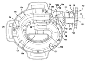
Figure 12 shows a side, cross-sectional view of another embodiment of a device for storing laser optical fibers, in accordance with the present invention.
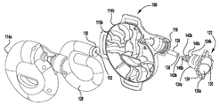
Figure 13 shows an expanded view of another embodiment of a device for storing a laser optical fiber in accordance with the present invention.
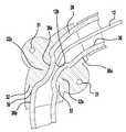
Figure 14 is a side view showing one aspect of another embodiment of a device for storing laser optical fibers, in accordance with the present invention.
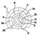
Figure 15 is an axial view of the inlet of another embodiment of a device for storing laser optical fibers, in accordance with the present invention.
이어지는 기재에서, 수많은 세부사항이 본 발명의 철저한 이해를 제공하기 위해 명시된다. 이러한 특정 세부사항의 변형은 본 발명의 결과를 달성하기 위해 가능하다는 것을 당업자는 이해할 것이다. 본 발명의 기재를 쓸데없이 모호하게 하는 것을 피하기 위해, 잘 알려진 처리 단계 및 물질들은 일반적으로 상세하기 기재되지 않는다.
In the following description, numerous details are set forth in order to provide a thorough understanding of the present invention. Those skilled in the art will understand that variations of these specific details are possible to achieve the results of the present invention. In order to avoid unnecessarily obscuring the substrate of the present invention, well known processing steps and materials are generally not described in detail.
이어지는 기재에서, 예시적인 치수는 본 발명의 예시적인 실시예에 대해 제공될 수 있다. 이 치수는 제한하기 위한 것으로 해석되지 않아야 한다. 치수는 바율의 의미를 제공하기 위해 포함되어 있다. 일반적으로 말하면, 그것들이 배치되어 있는 곳의 다양한 요소, 대조적인 구성요소 사이의 관계이고, 중요한 그들의 상대적인 크기이다.
In the description that follows, exemplary dimensions may be provided for exemplary embodiments of the invention. This dimension is not to be construed as limiting. Dimensions are included to provide the meaning of the bar percentage. Generally speaking, it is the relationship between the various elements, the contrasting elements, where they are placed, and their relative size, which is important.
도1 및 2를 살펴보면, 레이저 광섬유를 일시적으로 저장하기 위한 디바이스(10, 이하 "디바이스")가 표시된다. 디바이스(10)는 긴 유연성 레이저 광섬유(12)의 자유단 부분(12a)을 일시적으로 저장하기 위한 레이저 광섬유 저장 디바이스로 설계된다. 디바이스(10)는 자유 단부(16)를 갖는 저장 하우징(14)을 포함한다.저장 하우징(14) 안에 레이저 광섬유(12)의 자유 단부를 일시적으로 배치함으로써, 이 자유 단부가 모든 잠재적 오염원 또는 잠재적 파손으로부터 보호될 수 있고, 레이저 광섬유로부터 우연히 방전되는 임의의 레이저 광이 저장 하우징 안에 안전하게 보관된다. 바람직하게는 디바이스(10)는 레이저 방사선을 방출하기 위해 레이저 소스(표시되지 않음)에 연결되는 레이저 광섬유를 내과의사가 사용하는 의료시술 중에 사용되도록 설계된다. 디바이스(10)는 일회용 기구로 설계되거나, 살균되어 여러 번 사용되도록 설계될 수 있다. 바람직하게는 디바이스(10)가 의료 시술 중에 사용되기는 하지만, 모든 종류의 환경에서 레이저 광섬유를 보호하기 위해 사용되는 것은 본 발명의 범위 안에 있다.
1 and 2, a device 10 (hereinafter " device ") for temporarily storing a laser optical fiber is shown. The
디바이스(10)의 상부, 측면, 하부에 부착될 수 있는 링형 돌출부(17)가 다수 개 있다. 링(17)은 벨크로 띠, 유연한 탄성 양면 접착제 또는 다른 모든 적합한 부착 수단을 수단으로 환자에게 디바이스(10)를 부착하기 위해 사용된다. 디바이스(10)은 일반적으로 환자의 다리에 부착하도록 설계되지만, 환자 신체의 다른 부분 또는 소독 또는 수술실에 인접한 비-환자 위치에 디바이스(10)를 부착하는 것은 본 발명의 범위 안에 있다.
There are a number of ring-shaped
바람직하게는 디바이스(10)는 개방 단부(16)를 갖는 하우징(14)으로 구성된다. 저장 하우징(14)은 서로의 거울 이미지인 두 개의 우묵한 저장 하우징 부분(14a, 14b)으로 구성될 수 있다. 하우징 부분(14a, 14b)이 도1, 2, 5에 표시된 바와 같이 서로 접합되면, 나선형 채널(18)을 구성한다. 나사(19)가 하우징 부분(14a, 14b)을 서로 접합하기 위한 수단으로 표시되었지만, 접착제를 사용하는 것처럼 모든 바람직한 방법으로 접합하는 것은 본 발명의 범위 안에 있다. 저장 하우징(14)은 예를 들어 플라스틱, 실리콘, 중합체 및 알루미늄과 같은, 그러나 이에 한정되지는 않는 다양한 물질로 제작될 수 있다.
Preferably the
하우징(14)의 개방 단부(16)는 개방 단부를 따라 연장되는 통로(22)를 갖는 깔때기(20)를 수용한다. 통로(22)의 일단은 광구(20a)를 구성하고 통로의 반대쪽 끝은 긴 유연성 튜브(28)를 따르는 통로(30)에 맞추어 조정된다. 광구 맞은 편 깔때기의 단부로부터 연장되는 원통형 단부 커넥터를 제공하는 것처럼, 그러나 이에 한정되지는 않은 모든 소정의 수단에 의해 하우징(14) 내에 배치되는 깔때기(20)의 단부에 튜브(28)의 일단부가 부착될 수 있는데, 긴 유연성 튜브(28)의 통로(30)가 그 위에 강제로 놓일 수 있다. 깔때기(20)의 재질은 하우징(14)의 나머지처럼, 레이저 에너지 불투과성으로 설계된다. 바람직하게는 모든 플라스틱 구성요소는 내열성이지만, 반드시 레이저 에너지 불투과성은 아니다.
The
깔때기(20)를 관통하는 내부 통로(22)는 튜브(28)를 관통하는 통로(30)에 맞추어 조정된다. 예시적인 튜브(28)에서, 튜브(28)의 통로(30)는 약 1.7㎝의 직경, 약 0,1㎝ 내지 약 1㎝의 내부 직경, 튜브의 약 0.3㎝ 내지 약 1㎝일 수 있는 벽 뚜께를 갖는다. 기재된 이러한 크기는 다른 적합한 크기의 사용을 불가능하게 하기 위한 것이 아니다.
The
도2를 살펴보면, 저장 하우징(14)의 일 측면(14b)이 보인다. 도5에 보이는 바와 같이, 하우징(14)은 긴 유연성 레이저 광섬유(12)의 자유 단부(12a)를 일시적으로 저장하기 위해 저장 하우징(14) 또는 리셉터클을 구성하는 두 개의 마주보는 결합부(14a, 14b)를 포함한다. 긴 섬유(12)는 깔때기(20)를 통해 연장되는 통로(22)를 통해 저장 하우징(14) 안에 삽입된다. 깔때기의 광구(20a)는 레이저 광섬유(12)의 말단(12b)을 저장 하우징(14) 내에 바람직하게는 나선형 구조로 배치되는 긴 고무 튜브(28) 안으로 안내한다. 하우징(14)은 실리콘 고부 튜브(28) 내에 감긴 구조로 레이저 광 섬유(12)의 자유 단부(12a)를 삽입하고 유지하여 레이저 광섬유의 자유 단부를 하우징으로부터 완전히 제거할 수 있도록 한다.
2, one
도2에 보이는 바와 같이, 결합 측면부(14b)로부터 연장되는 다수의 이격된 리브(24b)와 측면부(14a)의 내부 측면으로부터 밖으로 향해 연장되는 다수의 이격된 리브(24a)의 매칭이 있다. 각각의 리브(24a, 24b)는 이하 기재되는, 각각 튜브(24)를 수용하는 크기인 반원형 컷아웃(26a, 표시되지 않음)을 가지기 때문에, 두 측면(14a, 14b)이 함께 고정되는 경우, 튜브(28)는 결합하는 한 쌍의 리브(24a, 24b)가 서로 맞물리는 경우 구성되는 반원형 컷아웃(26a, 26b)에 의해 구성되는 원형 개구(29, 도3 참조)에 의해 둘러싸인다. 원형 개구(29)는 감긴 구조로 긴 유연성 튜브(28)를 구성하기 위해 나선형 경로를 구성한다.
As shown in FIG. 2, there is a matching of a number of spaced
리브(24a, 24b)는 저장 하우징(14) 안에 튜브(28)를 배치하는 역할을 한다. 도2를 살펴보면, 리브(24a, 24b)는 깔때기(20)의 원통형 스템(20b)으로부터 하우징 내에서 나선형을 그리며 튜브(28)가 돌도록 하여 튜브(28)를 관통하는 통로(30)의 내부 직경을 통로(22)에 맞춰 조정한다. 통로(22)는 튜브 통로(30)보다 작은 직경을 가지기 때문에 긴 섬유(12)의 말단(12b)이 통로(33)를 통해 튜브 통로(30) 안으로 들어가는 경우, 쉽게 통로(30)를 통해 그 안으로 이동할 것이다.
긴 유연성 튜브(28)는 대체로 레이저 광섬유(12)를 통해 발사된 의료용 레이저빔에 노출되는 경우 불이 나지 않도록 선택된다. 또한, 튜브(28)는 적어도 약 1초 내지 5초의 소정의 시간 동안 의료용 레이저 빔에 노출되는 경우 용락을 견딜 수 있다.
The elongate
긴 유연성 튜브(28)가 소정의 시간 동안 의료용 레이저 빔에 노출되는 경우 용락을 견딜 수 있는 어떤 소정의 물질로 제작될 수 있지만, 바람직한 물질은 백금 경화 실리콘 고무 튜브처럼, 실리콘이다.
The long
튜브(28)의 제 1 부분(28a)은 깔때기(20)의 원통형 스템(20b)과 흐름 제한장치(32, 추후 기재) 사이로 연장된다. 튜브(28)의 제 1 부분(28a)은 튜브(28)의 나머지 보다 두꺼운 벽을 가질 수 있다. 더 두꺼운 이 벽은 도3a에 보이는 바와 같이 튜브(28)를 둘러싸는 추가 튜브(34)에 의해 구성될 수 있다. 그 대신에, 도3a에 보이는 바와 같이 튜브(28a)의 더 두꺼운 벽을 생성하기 위해 오버몰딩에 의해 부분(28a)이 구성될 수 있다. 물론, 부분(28a)에서, 튜브형 통로(30)는 튜브(28)의 나머지 부분을 통해 동일한 직경을 갖는다.
The
튜브(28)의 적어도 일부(28a)를 더 큰 벽 두께로 구성하는 목적은 측면 발사형 레이저 광섬유(12)로부터 방출된 레이저 광으로부터의 용락을 방지하기 위한 것이다. 측면 발사 레이저 광섬유가 일반적으로 섬유의 단부 바깥으로부터 직접 레이저 빔을 방출하는 종래의 레이저 광섬유보다 큰 직경을 갖는 것은, 이후 논의되는 것처럼, 흐름 제한장치(32) 안에 배치되는 튜브(30)의 섹션을 마주하는 경우 측면 발사형 레이저 광섬유(12)가 잡힐 경향이 있다는 것이다.
The purpose of constructing at least a
도4를 살펴보면, 흐름 제한장치(32)를 따라 긴 유연성 튜브(28)가 보인다. 흐름제한장치(32)는 도2에 보이는 바와 같이 튜브(28)가 젖혀지는 영역에서 저장 하우징(14) 내에 배치될 수 있다. 흐름 제한장치(32)는 흐름 제한장치의 양 측면상에 홀(31)을 따라 나사를 포함하는 다양한 수단에 의해 저장 하우징에 부착될 수 있다. 흐름 제한장치(32)는 튜브(28)를 수용하도록 크기가 적응된 내부 보어(36, bore)를 갖는다. 흐름 제한장치(32)의 마주보는 측면에 있는 내부 보어(36)의 원통형 부분(36a, 36b)은 일반적으로 원형이고 튜브(28)의 외부 직경에 해당하는 직경을 갖는다. 흐름 제한장치(32)의 중심부에서, 내부 보어(36)의 중심부(36c)는 목이 좁아져서(neck-down) 튜브(28)의 직경과 튜브(28)를 따르는 통로(30)의 내부 직경이 도4에 보이는 바와 같이, 중심부(32a)에서 모두 줄어든다.
4, a long
흐름 제한장치(32)가 예시되어 있지만, 튜브(28)를 밀어넣기 위해 리브(24a, 24b)를 사용하도록 하는 본 발명의 개념 안에 존재한다. 이것은 하나 이상의 인접한 매칭 리브 쌍(24a, 24b) 안의 컷아웃 쌍(26a, 26b)에 의해 구성된 개구부(29)를 생성함으로써 달성될 수 있다. 이 실시예에서, 하우징(14)의 양쪽(14a, 14b)이 하우징(14)의 하나의 반쪽(14a 또는 14b) 안에 있는 긴 유연성 튜브(28)과 조립되는 경우, 하나 이상의 매칭 리브 쌍(24a, 24b) 안의 컷아웃 쌍(26a, 26b)에 의해 구성된 개구부(29)의 직경이 감소하는 부분에서 더 작은 작경 안으로 긴 유연성 튜브(28)가 밀어 넣어질 수 있다.
Although
흐름 제한제한장치(32)를 구비한 튜브(28)의 내부 직경을 감소시키는 목적은 도4에 일반적으로 보이는 바와 같이 원통형 부분(36a)을 따라 연장되는 더 큰 레이저 광섬유(12)의 단부(12b)를 잡기 위한 것이다. 튜브(28)의 넥다운부에서 단부(12)가 멈추게 하는 것은 측면 발사 레이저 광섬유가 우연히 잘못 발사되는 경우, 광이 튜브(28)의 더 두꺼운 부분(28a)으로만 향하여, 어떤 레이저 광도 하우징(14)로부터 빠져나오지 못하게 한다. 더 작은 직경을 갖는 레이저 광섬유(12)를 사용하면, 섬유는 튜브의 목이 좁아진 부분을 따라 더욱 쉽게 통과하고 이하 기재된 바와 같이 튜브를 계속 내려뜨릴 것이다.
The purpose of reducing the inner diameter of the
도2를 살펴보면, 튜브(28)의 부분(28c)은 흐름 제한장치(32)를 지나 하우징(14)의 내부 주변부를 따라 감기는 것을 지속하고, 하우징의 개구(16)의 일반적인 방향으로 연장된다. 다음으로, 리브(24a, 24b)의 배치 때문에, 튜브의 부분(28d)은 흐름 제한장치(32) 방향으로 되돌아간다. 마지막으로, 튜브(28)의 부분(28e)의 단부는 개구(16) 방향으로 연장되고 플러그(도시되지 않음)와 같은 어떤 수단에 의해 또는 튜브를 뒤로 접음으로써 막을 수 있다.
2, the
더욱 얇은 광 필라멘트가 흐름 제한장치(32)를 따라 통과하는 경우, 단부(28e)까지 도달하는 것이 가능할 것이다. 레이저 광의 우연한 방전 사고시, 광은 폐쇄 단부(28f)를 따라갈 수 없을 것이고, 따라서 레이저 광은 하우징(14)으로부터 빠져나오지 못할 것이다.
If thinner light filaments pass along the
하우징(14)의 추가적인 모양, 즉 하우징의 3차원 모양이 도5에 보이고, 도6은 하우징의 측면도으로, 하우징의 저면도이다.
An additional shape of the
디바이스(40, 디바이스(10)과 유사한)의 다른 실시예가 도7에 디스플레이되는데, 저장 하우징(41, 하우징(14)과 유사한)과 함께 사용하는 레이저 광섬유 클램프의 측면 삼차원도이다. 레이저 광섬유 클램프(42)의 목적은 시술 도중에 디바이스(40)를 사용하는 동안 레이저 광섬유(121)가 저장 하우징(41) 안의 제자리에 남아있도록 하는 것이다. 레이저 광섬유 클램프(42)의 클램핑 메커니즘은 2 및 4 파운드 사이의 압박하는 힘에 의해 꽉 물려 있는 레이저 광섬유(12)의 움직임을 방지한다.
Another embodiment of device 40 (similar to device 10) is displayed in FIG. 7, which is a side three-dimensional view of a laser fiber optic clamp for use with storage housing 41 (similar to housing 14). The purpose of the laser
시술 도중에, 레이저 광섬유(12)와 같은 레이저 광섬유는 레이저 에너지 소스(43)에 일 단부(12a)에서 고정된다. 레이저 광섬유의 반대쪽 단부(12b)는 보통 수술기구(도시되지 않음)에 연결된다. 그러나, 레이저 광섬유(12)의 자유 단부(12b)가 수술기구로부터 분리되는 경우, 반대쪽 단부(12a)가 여전히 레이저 에너지 소스(43)에 연결되어 있어도, 자유 단부(12b)는 시술 도중에 헐거워지고 자유롭게 움직이게 된다. 이러한 자유로운 움직임은 쉽게 레이저 광섬유(12)가 부러지거나 무균상태를 잃게 할 수 있다. 또한, 이하 논의되는 바와 같이, 자유로운 레이저 광섬유(12)는 레이저 광섬유가 우연히 꺼지는 사고시 환자 또는 의료 인력의 심각한 상해를 초래할 수 있다.
During the procedure, a laser optical fiber, such as laser
현재, 레이저 에너지 소스에 부착되어, 수술실의 환자, 의료 인력 또는 일부 디바이스에 손상을 주거나 멸균이 유지되지 않은 상태가 되도록 하는 파손을 당하지 않도록 하는, 레이저 광섬유의 자유 단부를 고정시키도록 설계된 디바이스는 의료 시장에 존재하지 않는다. 일부 장소에서 레이저 광섬유(12)의 자유 단부(12b)를 보호하기 위해 자유 단부의 움직임이 제어될 수 있도록 하는 것이 바람직할 것이다. 저장 하우징(41)과 레이저 광섬유 클램프(42)의 조합은 이 문제를 완화시키는데, 레이저 광섬유(12) 상의 임의의 위치에 고정되어 섬유를 안정화시키고 저장 하우징(41)으로부터의 움직임을 방지한다. 레이저 광섬유(12)의 안정화는 시술을 지휘하는 의료진에게 상당한 혜택이다.
Currently, devices designed to secure a free end of a laser fiber that are attached to a laser energy source to prevent damage to the patient, medical personnel, or some devices in the operating room or to leave them sterile are not maintained. It doesn't exist in the market. It may be desirable to allow the movement of the free end to be controlled in some places to protect the
레이저 광섬유 클램프(42)는 바람직하게는 플라스틱 폴리머로 제조된다. 디바이스(10)와 마찬가지로, 레이저 광섬유 클램프(42)는 클램프 내에 배치된 섬유 부분을 통해 레이저 광섬유(12)의 우연한 오발이 있을 수 있는 환자 및 의료진을 보호하는 능력을 갖는다. 본 실시예에 예시된 바와 같이 레이저 광섬유 클램프(42)가 레이저 광섬유의 길이를 따르는 어떤 위치에 레이저 광섬유(12)를 고정하는데 효과적이고 레이저 광섬유(12)의 움직임을 제한하도록 설계되었지만, 저장 하우징(41)을 갖는 임의의 형태 또는 디자인의 클램프를 저장 하우징(41)과 결합하기 위한 본 발명의 조항 안에 있다.
The laser
도8 및 도11을 살펴보면, 레이저 광섬유 클램프(42)의 구성요소의 상세한 모양이 도시된다. 정렬되어 레이저 광섬유 클램프(42)가 닫힐 경우 도7에 도시된 바와 같이 레이저 광섬유(12)를 고정할 수 있는 된 두 개의 동일한 클램핑 섹션(42a, 42b)이 존재한다. 각각의 클램핑 섹션(42a, 42b)은 각각(도11에 도시된 바와 같이) 마주보는 클램핑 섹션의 움푹 패인 팬 리셉터클(46a, 도시되지 않음) 안에 선회할 수 있도록 배치되는 곡면을 구비하여 움푹 패인 리셉터클에 대해 클램핑 섹션이 선회할 수 있는, 하나의 돌출부(44a, 44b(도시되지 않음))를 갖는다.
8 and 11, the detailed shape of the components of the laser
두 개의 클램핑 섹션(42a, 42b)이 서로 고정되어 돌출부(44a, 44b)가 움푹 패인 리셉터클(46a, 46b) 내에 배치되는 경우, 두 개의 클램핑 섹션(42a, 42b)은 일반적으로 u-형 스프링(48)에 의해 함께 선회하도록 고정된다. 스프링(48)은 각각의 클램핑 섹션(42a, 42b)의 핸들 부분(52a, 52b) 안에 각각 구성된 개방 중심 슬롯(50a, 50b) 내에 배치된다. 클램핑 섹션(42a, 42b)을 함께 누르는 스프링 바이어스 힘을 가하기 위해 스프링(48)의 개방 단부(48a, 48b)가 클램핑 섹션(42a, 42b)의 외부 절단 섹션(54a, 54b) 안에 각각 배치되어, 각각의 클램핑 섹션(42a, 42b)의 안쪽을 향하는, 마주보는 면(42c, 42d)은 거기를 따라 연장되는 마주보는 오목면(42e, 42f)에 의해 구성되고 레이저 광섬유(12)를 수용하도록 적응된 중공의 중심 통과 통로(58, 도11 참조)를 갖는 원통형 클램프(42)를 구성한다. 스프링(48)은 두 개의 클램핑 섹션(42a, 42b)이 함께 조여지게 하는 스프링 인가 힘을 제공한다. 사용자는 클램핑 섹션(42a, 42b)의 두 개의 핸들 부분(52a, 52b)에 압력을 인가함으로써 레이저 광섬유 클램프(42)를 작동시켜 클램핑 섹션이 도9에 도시된 바와 같이 개방 조건으로 선회하도록 한다.
When the two clamping
각각의 클램핑 섹션(42a, 42b)은 각각 고무줄(62a, 62b, 상세한 모양은 도9에 도시됨)을 수용하는 클램핑 섹션의 중심부를 따라 개구(60a, 60b)를 갖는다. 각각 고무줄(62a, 62b)은 각각 스프링(48)의 자유 단부(48a, 48b)에 의해 개구(60a, 60b)의 제자리에 고정된다. 레이저 광섬유 클램프(42)가 조립되는 경우, 두 개의 고무줄(62a, 62b)은 도7 및 도11에 도시된 바와 같이 맞물린다. 스프링(48)에 의해 생성된 힘 때문에, 고무줄(62a, 62b)은 서로에 대해 단단하게 눌러진다. 사용시에, 레이저 광섬유(12)는 중공 중심(58) 안쪽과 고무줄(62a, 62b) 사이에 배치되어 레이저 광섬유(12)가 특히 시술 중에 디바이스(10) 내에 배치되는 경우, 서로 움직이지 않도록 한다.
Each
클램핑 섹션(42a, 42b)의 각각의 단부에는 돌출부(64a, 64b, 64c, 64d)가 존재한다. 이 돌출부들(64a ~ 64d)은 전면 삽입부(70)를 통해 저장 하우징(41)에 레이저 광섬유 클램프(42)를 단단하게 장착하도록 설계된다. 원통형 구조물(46)의 마주보는 단부 상에 배치된 돌출부(64a ~ 64d)는 전면 삽입부(70) 내에 레이저 광섬유 클램프(42)의 두 단부가 고정되는 것을 허용한다.
At each end of the clamping
도7에 도시된 바와 같이, 전면 삽입부(70)는 제 1 단부(70)에서 저장 하우징(41)의 개방 단부(41a)에 고정된다. 전면 삽입부(70)는 제 1 단부(70)로부터 제 2 단부(70b)로 연장되는 중공의 중심 구멍(72)을 갖는다. 레이저 섬유 클램프(42)는 저장 하우징(41)의 건너편의, 제 2 단부(72b)에서 개구(74)에 제거가능하게 장착된다. 전면 삽입부(70)는 도8에 도시된 바와 같이 리시버 키(76)를 갖는데, 원통형 구조물(46)의 양단부의 돌출부(64a, 64c) 또는 돌출부(64b, 64d)를 수용한다. 원통형 구조물(46)이 전면 삽입부(70)의 리시버 키(76) 안으로 삽입되는 경우, 레이저 광섬유 클램프(42)는 전면 삽입부에 대해 약 90°회전시킴으로써 단단하게 고정된다.
As shown in FIG. 7, the
돌출부(56a, 56c) 또는 돌출부(56b, 56d)는 저장 하우징(41) 내에 레이저 광섬유 클램프(42)를 고정하여 리시버 키(76)로부터 돌출부(56a, 56c) 또는 돌출부(56b, 56d)가 풀리게 하도록 양방향으로 90°회전할 때까지는 레이저 광섬유 클램프(42)를 제거할 수 없도록 한다.
The protrusions 56a and 56c or the protrusions 56b and 56d hold the laser
레이저 광섬유 클램프(42)를 활용하기 위해, 사용자는 먼저 두 개의 핸들 부분(52a, 52b)을 잡아당겨 도9에 도시된 바와 같이 개방 위치에 레이저 광섬유 클램프(42)가 놓이도록 한다. 원통형 구조물(46)은 서로로부터 내부를 향하는, 마주보는 표면(42c, 42d)을 분리하기 위해 15°및 35°사이의 범위에서 개방될 수 있다. 다음으로, 레이저 광섬유(12)는 원통형 구조물(46) 내에 놓이고, 핸들 부분(52a, 52b)이 풀려서 레이저 광섬유(12)가 고무줄(62a, 62b) 사이에 단단하게 고정된다. 레이저 광섬유 클램프(42)로부터 돌출되는 레이저 광섬유(12)의 단부는 저장 하우징(41) 내에 꼭 맞도록 충분히 길어 저장 하우징 안에 고정되도록 한다. 다음으로, 원통형 구조물(46)은 전면 삽입부(70) 안으로 삽입되어 레이저 광섬유(12)가 도7에 도시된 바와 같이 저장 하우징(41) 안으로 상당 거리 연장된다. 다음으로, 원통형 구조물(46)은 전면 삽입부(70) 내에서 약 90°회전하여 돌출부(64a, 64c)가 리시버 키(76) 내에 원통형 구조물(46)을 고정하도록 한다. 일단 클램프(42)가 전면 삽입부(70) 내에 고정되면, 클램프는 열리지 않는다.
To utilize the laser
레이저 광섬유 클램프(42)가 저장 하우징(41)과 결합하여 사용되도록 도시되고 기재되었지만, 레이저 광섬유가 고정될 필요가 있는 다양한 애플리케이션에서 별도로 사용하기 위해 본 발명의 용어 내에 있다.
Although the laser
도12 및 도13을 살펴보면, 레이저 광섬유(12)를 일시적으로 저장하기 위한 다른 구현 디바이스(100, 이하 "디바이스")가 도시된다. 디바이스(100)은 디바이스(10)와 동일한 기능을 수행하지만 이하 논의되는 바와 같이 몇몇 추가적인 특성을 포함한다는 것에 주목하라. 디아비스(100)는 긴 유연성 레이저 광섬유(12)의 자유 단부 섹션(12a)을 저장하기 위한 레이저 광섬유 저장 시스템으로 설계된다. 디바이스(100)는 개방 단부(116)를 갖는 저장 하우징(114)을 포함한다. 디바이스(10)처럼, 레이저 광섬유(12)의 자유 단부(12a)를 저장 하우징(114)에 일시적으로 배치함으로써, 자유 단부가 오염 또는 잠재적 파손의 임의의 잠재적인 소스로부터 보호되고, 레이저 광섬유로부터의 우연히 방전된 모든 레이저 광이 저장 하우징 내에 안전하게 보관된다.
12 and 13, another implementation device 100 (hereinafter “device”) for temporarily storing a laser
디바이스(100)의 상면, 측면, 저면에 부착될 수 있고 다른 적합한 부착 수단에 의해 환자에게 디바이스(100)를 부착하도록 사용될 수 있는 링형 돌출부(118)가 다수개 있다.
There are a number of ring-shaped
디바이스(100)는 바람직하게는 서로에 대해 거울상인, 두 개의 중공의 저장 하우징 섹션(114a, 114b)로 구성된 저장 하우징(114)로서 제작된다. 하우징 섹션(114a, 114b)이 도12에 도시된 바와 같이 함께 연결되면, 하우징 섹션(114a, 114b) 안에 구성된 리브(115a, 115b)는 각각 서로 맞물리고 나선형 채널(119)을 구성한다. 하우징 섹션(114a, 114b)는 스크류와 같은 임의의 수단에 의해 함께 연결된다. 저장 하우징(114)은 예를 들어 플라스틱, 실리콘, 폴리머 및 알루미늄과 같은 다양한 물질, 그러나 이에 한정되지는 않는 물질로 제작될 수 있다.
The
하우징(114)의 개방 단부(116)는 도14에 도시된 바와 같이 깔때기 형상의, 내부 섹션(122)와 연결되는 나삿니가 있는 섹션(120)을 갖는다. 깔때기 형상의 내부 섹션(122)는 나선형 채널(119) 내에 고정된 긴 유연성 튜브(128)를 따라 연장되는 통로(126)의 개방 단부에 맞추어 적응되는 배출구(122a)를 갖는다.
The
레이저 광섬유 클램프(123)는 시술 중에 디바이스(100)를 사용하는 중 저장 하우징(114) 내에서 레이저 광섬유(12)가 제자리에 유지되는 것을 보장하도록 개구(126)에서 하우징(114)에 제공된다. 레이저 광섬유 클램프(123)의 클램핑 메커니즘은 2 내지 4 파운드사이의 힘으로 압박함으로써 꽉 물려진 레이저 광섬유(12)의 이동을 방지한다.
The laser
클램프(123)는 나삿니가 있는 섹션(120) 내에 클램프를 나사모양으로 장착하기 위해 원통형 섹션(124a)으로부터 바깥쪽으로 연장되는 나사산(132)과 원통형 섹션(124a)을 따라 연장되는 내경(130, 도13 참조)을 갖는 나삿니가 있는 캡(124)를 포함한다. 내경(130)의 일단(130a)은 넓은 입구를 구성하는 반면 보어(130)의 반대쪽 단(130b)은 유연성 튜브(138)를 따라 연장되는 통로(136)에 개방되는데, 유연성 튜브(138)는 탄성 중합체 또는 실리콘 고무 처럼, 레이저 에너지를 투과시킬 수 없도록 설계되는 물질로 제작될 수 있다. 유연성 튜브(138)는 원통형 색션(124a)의 단부(124b)로부터 바깥쪽으로 돌출된 한쌍의 외팔보형, 컴플라이언트 아암(140a, 140b) 사이에 배치된다. 컴플라이언트 아암(140a, 140b)은 도15에 도시된 바와 같이 유연성 튜브(138)를 수용하는 오목한 내부 표면(142a, 142b)을 가질 수 있다. 각각의 컴플라이언트 아암(140a, 140b)은 도15에 도시되고 이하 기재되는 바와 같이 컴플라이언트 아암이 튜브(138)를 압축하고 서로를 향해 이동할 수 있게 하도록 액티브 힌지를 제공하는 슬롯(144a, 144b)을 가질 수 있다.
도14에 도시된 바와 같이, 광섬유(12)는 클램프(123)를 따라 연장되는 내경(130) 안에 삽입될 수 있다. 넓은 입구 섹션(130a)은 도13에 도시된 바와 같이, 섬유를 내경 안으로 인도한다. 섬유가 단부(130)를 따라 내경(130)을 나오면, 유연성 튜브(138)를 따라 내경(136) 안으로 인도한다(도13 참조). 섬유가 캡(123) 및 튜브(138)를 따라 삽입되는 경우, 깔때기형 내부 섹션(122)의 벽은 배출구(122a)를 따라 섬유를 인도한다.
As shown in FIG. 14, the
교차하는 다수의 슬릿(152)을 가진 유연성 디스크(150)는 유연성 튜브(128)를 따라 관통하는 통로(126)의 주입구(126a)와 깔때기 모양 내부 섹션(122)의 배출구(122a) 사이에 배치된다. 유연성 디스크(150)은 리브(115)에 의해 제자리에 제거가능하게 고정될 수 있다. 유연성 디스크(150)의 목적은 교차하는 슬릿(152)을 구부림으로써 형성되는 개구를 따라 섬유가 움직이는 동안 사용자가 섬유(12)의 존재를 느낄 수 있도록 하는 것이다.
A
긴 유연성 튜브(128)는 약 1.7㎝의 외경을 갖고, 내부 통로(126)는 약 0.1㎝ 내지 약 1㎝의 직경을 가지며, 튜브(128)의 벽 두께는 약 0.3㎝ 내지 약 1㎝일 수 있다.The long
도13 및 도14를 살펴보면, 저장 하우징(114)의 일 측면(114b)가 도시된다. 하우징(114)은 레이저 광섬유의 자유 단부 섹션의 제거를 완료할 수 있게 하기 위해서 실리콘 고무 튜브(128) 내의 코일형 구조안에 레이저 광섬유(12)의 자유 단부 섹션(12a)를 삽입하고 보유하도록 구성된다.
13 and 14, one
도13 및 도14에 도시된 바와 같이, 일치하는 측면 섹션(114b)으로부터 연장되는 이격된 다수의 리브(115b) 및 측면 섹션(114a)의 내부 측면으로부터 외부로 연장되는 이격된 다수의 매칭되는 리브(115a, 도시되지 않음)가 존재한다. 각각의 리브(115a, 115b)는 각각 튜브(128)을 수용할 수 있는 크기의 반원형 컷아웃(117a, 117b)을 갖기 때문에, 이하 기재된 바와 같이, 두 측면(114a, 114b)이 함께 고정되는 경우, 튜브(128)는 매칭되는 리브 쌍(115a, 115b)이 서로 맞물리는 경우 구성되는 반원형 컷아웃(117a, 117b)에 의해 구성된 원형 개구로 둘러싸인다. 원형 개구는 도13에 도시된 바와 같이 나선형 경로를 구성하여 코일형 구조안에 긴 유연성 튜브(128)를 형성하도록 한다.
As shown in Figures 13 and 14, a plurality of spaced apart
긴 유연성 튜브(128)는 레어지 광섬유(12)를 따라 발사된 의료용 레이저 빔에 노출되는 경우 대체로 타지않도록 선택된다. 게다가, 튜브(128)는 적어도 약 1초 내지 약 5초의 시간 동안 의료용 레이저 빔에 노출되는 경우 용락을 견딜 수 있다.
The elongate
긴 유연성 튜브(28)는 적어도 소정의 시간 동안 의료용 레이저 빔에 노출되는 경우 용락을 견딜 수 있는 임의의 소정의 물질로 제작될 수 있는데, 바람직한 물질은 백금 경화형 실리콘 고무 튜빙과 같이, 실리콘이다.
The elongate
제 1 실시예의 튜브(28)와 마찬가지로, 튜브(128)의 내경은 튜브(128)를 압박함으로써 줄어든다. 이것은 섹션(128a)에서 튜브(128)의 내경을 더 작은 직경으로 밀어넣기에 크기가 알맞은 반원형 컷아웃(117a, 117b)에 의해 구성된 원형 개구의 섹션을 생성함으로써 달성될 수 있다.
As with the
앞서 언급한 바와 같이, 튜빙(128)의 내경을 줄이는 목적은 도14에 일반적으로 도시된 바와 같이 섹션(128a)를 따라 연장되는 더 큰 레이저 광섬유(12)의 단부(12b)를 잡는 것이다. 이하 서술하는 바와 같이, 더 작은 직경을 갖는 레이저 광섬유(12)를 사용하면, 섬유는 튜브의 목이 좁아지는 섹션을 더욱 쉽게 통과하고 튜브를 내리는 것을 지속할 것이다.
As mentioned above, the purpose of reducing the inner diameter of the
튜브(128)의 단부 섹션(128b)는 플러그(도시되지 않음)와 같은 임의의 수단에 의해 또는 반원형 컷아웃(117a, 117b)에 의해 구성된 원형 개구의 직경을 감소시킴으로써 섹션(128a)에서 튜브의 내경을 더 작은 직경안으로 밀어넣음으로써 폐쇄될 수 있다.
The
얇은 광 필라멘트가 튜브(128)의 섹션(128a)을 통과하는 경우, 단부 섹션(128b)까지 가는 것이 가능할 것이다. 레이저 광의 우연한 방전 사고시, 광은 폐쇄된 단부(128b)를 통과하지 못할것이며, 따라서 레이저 광은 하우징(114)로부터 빠져나오지 못할 것이다.
If a thin light filament passes through the
시술 도중과 같은 작동시, 레이저 광섬유(12)와 같은 레이저 광 섬유는 일 단부(12a)에서 레이저 에너지 소스(43)에 고정된다(도7 참고). 레이저 광섬유의 마주보는 단부(12b)는 일반적으로 수술 도구(도시되지 않음)에 연결된다. 그러나, 레이저 광섬유(12)의 자유 단부(12b)가 수술 도구로부터 분리되는 경우, 마주보는 단부(12a)가 여전히 레이저 에너지 소스(43)에 고정되어 있더라도, 자유 단부(12b)는 시술중에 이동하도록 헐거워지고 자유로워진다. 이러한 이동의 자유는 쉽게 레이저 광섬유(12)가 파손되거나 무균성을 잃게 만든다. 또한, 앞서 논의된 바와 같이, 자유로운 레이저 광섬유(12)는 레이저 광섬유가 우연히 발사되는 사고시 환자 또는 의료진에게 심각한 상해를 야기할 수 있다.
In operation as during the procedure, a laser optical fiber, such as laser
자유 단부의 움직임을 제어할 수 있도록 어떤 위치에 레이저 광섬유(12)의 자유 단부를 고정하는 것이 바람직하다. 저장 하우징(114)과 레이저 광섬유 클램프(123)의 결합은 이러한 문제를 완화시키는데, 레이저 광섬유 상의 임의의 위치에 고정되어 섬유를 안정시키고 저장 하우징(114)으로부터의 움직임을 방지한다. 레이저 광섬유(12)의 안정화는 시술을 수행하는 의료진에게 아주 큰 혜택이다.
It is desirable to fix the free end of the laser
도14에 도시된 바와 같이, 광섬유(12)가 클램프(123)을 따라 연장되는 내경(130) 안으로 삽입될 수 있다. 넓은 입구 섹션(130a)은 도13에 도시된 바와 같이, 섬유를 내경 안으로 인도한다. 섬유가 단부(130b)를 따라 내경(130)을 나오면, 유연성 튜브(138)를 따라 내경(136) 안으로 인도된다(도13 참조). 섬유가 나삿니가 있는 캡(124) 및 튜브(138)를 따라 삽입된 후, 깔때기형 내부 섹션(122)의 벽은 배출구(122a)를 따라 섬유를 인도한다. 섬유가 하우징(114) 내에 고정되면, 디스크(150)를 통과한 다음 튜브(128)의 섹션(128a)에 접촉하거나 섬유가 단부(128a)까지 튜브(128) 안으로 더 이동한 후 섬유의 촉감에 의해 판단할 수 있는데, 나삿니가 있는 캡(124)은 도14에 도시된 위치로부터 회전하며, 여기에서 컴플라이언트 아암(140, 140b)은 서로 이격되어 섬유가 튜브(138)를 통과할 수 있도록 한다. 다음으로, 섬유(12)가 소정의 위치로 삽입되면, 나삿니가 있는 캡은 약 90°회전하여, 외팔보형 컴플라이언트 아암(140a, 140b)은 도15에 도시된 바와 같이 깔때기 모양 내부 섹션(122)의 벽에 대한 아암의 캠 동작에 의해 접촉된다. 컴플라이언트 아암은 튜브(138)를 압박하고 움켜쥐거나 광섬유를 제자리에 고정시킨다. 레이저 광섬유 클램프(123)의 클램핑 메커니즘은 고정된 레이저 광섬유(12)가 2 및 4 파운드 사이의 잡아당기는 힘에 의해 움직이는 것을 방지한다.
As shown in FIG. 14,
운전자가 섬유을 제거하고 싶으면, 나삿니가 있는 캡(123)은 반대 방향으로 약 90°회전하여 외팔보형 컴플라이언트 아암(140a, 140b)이 도14에 도시된 바와 같이 서로 분리되며 섬유(12)는 섬유에 어떤 손상도 야기하지 않고 제거될 수 있다.
If the operator wants to remove the fiber, the threaded
본 발명은 특정의 바람직한 실시예 또는 실시예에 대해 도시되고 서술되어 있지만, 이 명세서 및 첨부된 도면을 읽고 이해할 때 당업자에게 특정의 상응하는 변경 또는 수정이 발생할 것이다. 특히 전술된 구성요소(조립체, 디바이스 등)에 의해 수행되는 다양한 기능에 대해, 이러한 구성요소를 설명하기 위해 사용되는 용어("수단"을 참고로 포함)는 특별히 명시하지 않는 한, 여기에 도시된 본 발명의 예시적인 실시예에서 기능을 수행하는 개시된 구조와 구조적으로 동일하지는 않더라도, 기재된 구성요소(즉, 기능적으로 동일한)의 특정 기능을 수행하는 임의의 구성요소에 대응하기 위한 것이다. 또한, 본 발명의 특징 기능이 여러 실시예 중 하나에 대해 개시되어 있더라도, 이러한 기능은 임의의 주어진 또는 특정 응용에 대한 장점이 될 수 있는 다른 실시예의 하나 이상의 기능과 결합될 수 있다.While the present invention has been shown and described with respect to particular preferred embodiments or embodiments, certain corresponding changes or modifications will occur to those skilled in the art upon reading and understanding this specification and the accompanying drawings. In particular, for the various functions performed by the aforementioned components (assemblies, devices, etc.), the terms used to describe these components (including by reference to "means") are shown herein unless specifically indicated. Although not structurally identical to the disclosed structures for performing the functions in the exemplary embodiments of the present invention, it is intended to correspond to any component that performs a particular function of the described component (ie, functionally identical). In addition, although a feature function of the present invention may be disclosed for one of several embodiments, this function may be combined with one or more functions of other embodiments that may be advantageous for any given or particular application.
10, 100 : 레이저 광섬유 저장 디바이스
12 : 레이저 광섬유 14, 114 : 저장 하우징
28, 128 : 긴 유연성 튜브 32, 117a, 117b : 흐름 제한 장치
41 : 저장 하우징 42, 123 : 레이저 섬유 클램프
48 : 스프링 62a, 62b : 고무줄10, 100: laser optical fiber storage device
12:
28, 128: long
41:
48:
Claims (33)
상기 저장 하우징으로부터 빠져 나오는 레이저 광을 차단하기 위해 상기 긴 유연성 레이저 광섬유를 수용하도록 구성되는 상기 저장 하우징 내에 배치되는 긴 유연성 튜브(28, 128); 및
상기 긴 유연성 튜브의 내경을 줄이기 위한 상기 저장 하우징 내의 흐름 제한 장치(32, 117a, 117b)를 포함하는,
긴 유연성 레이저 광섬유(12)의 자유 단부(12a)을 일시적으로 저장하기 위한 레이저 광섬유 저장 디바이스(10, 100).
Storage housings 14, 114 having free ends 116;
An elongate flexible tube (28, 128) disposed within said storage housing configured to receive said elongate flexible laser optical fiber to block laser light exiting from said storage housing; And
Comprising flow restrictors 32, 117a, 117b in the storage housing to reduce the inner diameter of the elongate flexible tube,
Laser optical fiber storage device 10, 100 for temporarily storing the free end 12a of long flexible laser optical fiber 12.
상기 긴 유연성 레이저 광섬유(12)를 상기 저장 하우징 안으로 인도하도록 상기 저장 하우징(14, 114)의 개방 단부(16, 116) 내에 배치되는 깔때기(20, 122)를 더 포함하는
레이저 광섬유 저장 디바이스.
The method of claim 1,
And a funnel 20, 122 disposed in the open ends 16, 116 of the storage housing 14, 114 to guide the long flexible laser fiber 12 into the storage housing.
Laser optical fiber storage device.
깔때기(20)를 관통하는 접근 통로(22)는 긴 유연성 튜브(28)를 관통하는 통로(30)보다 작은 직경을 가져 상기 긴 유연성 레이저 광섬유(12)가 긴 유연성 튜브를 관통하는 통로로 들어갈 수 있도록 하는
레이저 광섬유 저장 디바이스.
3. The method of claim 2,
The access passage 22 through the funnel 20 has a smaller diameter than the passage 30 through the long flexible tube 28 so that the long flexible laser fiber 12 can enter the passage through the long flexible tube. So that
Laser optical fiber storage device.
상기 흐름 제한 장치(32)는 튜브(28)를 수용하는 내부 보어(36)를 포함하고, 상기 내부 보어는 튜브의 외경에 상응하는 직경을 갖는 두 개의 외부 섹션(36a, 36b)과, 통로(30)의 내부 직경 및 튜브의 직경을 줄이기 위해 상기 외경보다 작은 직경으로 목이 좁아지는 중심 섹션을 갖는
레이저 광섬유 저장 디바이스.
The method of claim 1,
The flow restrictor 32 includes an inner bore 36 for receiving a tube 28, the inner bore having two outer sections 36a, 36b having a diameter corresponding to the outer diameter of the tube, and a passageway ( 30) having a central section that narrows the neck to a diameter smaller than the outer diameter to reduce the inner diameter and the diameter of the tube.
Laser optical fiber storage device.
상기 흐름 제한 장치(32)는 상기 하우징(14)에 장착되는
레이저 광섬유 저장 디바이스.
The method of claim 1,
The flow restrictor 32 is mounted to the housing 14.
Laser optical fiber storage device.
상기 저장 하우징(14, 114)은 서로에 대해 거울상인 두 개의 중공 저장 하우징 반쪽(114a, 114b, 114a, 114b)으로 구성되는
레이저 광섬유 저장 디바이스.
The method of claim 1,
The storage housings 14, 114 consist of two hollow storage housing halves 114a, 114b, 114a, 114b that are mirror images of one another.
Laser optical fiber storage device.
두 개의 중공 저장 하우징 반쪽(114a, 114b, 114a, 114b)은 저장 하우징으로부터 연장되고 반원형 컷아웃(26a, 26b, 117a, 117b)을 갖는 이격된 다수의 리브(24a, 24b, 115a, 115b)를 각각 가져서, 두 개의 중공 저장 하우징 반쪽이 저장 하우징(14, 114)을 구성하기 위해 결합되는 경우, 이격된 리브 쌍들이 서로 일치하여 리브의 일치하는 쌍의 반원형 컷아웃이 튜브(28)를 감싸는 제 1 직경을 갖는 다수의 원형 개구(29)를 구성하는
레이저 광섬유 저장 디바이스.
The method according to claim 6,
The two hollow storage housing halves 114a, 114b, 114a, 114b extend from the storage housing and have a plurality of spaced ribs 24a, 24b, 115a, 115b having semicircular cutouts 26a, 26b, 117a, 117b. In each case, when two hollow storage housing halves are joined to form the storage housing 14, 114, the spaced rib pairs coincide with each other such that a matching pair of semi-circular cutouts of ribs surrounds the tube 28. Which constitutes a plurality of circular openings 29 having a diameter
Laser optical fiber storage device.
튜브의 직경 및 통로(30, 126)의 내부 직경을 줄이도록 튜브(28, 128)를 압박하기 위해 원형 개구(29)의 섹션은 제 1 직경보다 작은 제 2 직경을 갖는
레이저 광섬유 저장 디바이스.
The method of claim 7, wherein
The section of the circular opening 29 has a second diameter smaller than the first diameter to squeeze the tubes 28, 128 to reduce the diameter of the tube and the inner diameter of the passages 30, 126.
Laser optical fiber storage device.
원형 개구(29)는 나선형 경로를 구성하여 긴 유연성 튜브(28)를 코일형 구조로 형성하는
레이저 광섬유 저장 디바이스.
The method of claim 7, wherein
Circular openings 29 form a helical path to form long flexible tube 28 in a coiled configuration.
Laser optical fiber storage device.
깔때기(20)와 흐름 제한 장치(32) 사이의 튜브(28)의 제 1 섹션(28a)은 튜브의 나머지 부분보다 큰 벽 두께를 가져서 측면 발사 광섬유로부터 방출되는 레이저 광으로부터의 용락을 방지하는
레이저 광섬유 저장 디바이스.
3. The method of claim 2,
The first section 28a of the tube 28 between the funnel 20 and the flow restrictor 32 has a greater wall thickness than the rest of the tube to prevent melting from the laser light emitted from the side firing fiber.
Laser optical fiber storage device.
튜브(28)의 제 1 섹션(28a)은 외부 튜브(34)에 의해 덮이는
레이저 광섬유 저장 디바이스.
11. The method of claim 10,
The first section 28a of the tube 28 is covered by the outer tube 34.
Laser optical fiber storage device.
긴 유연성 튜브(28, 128)는 적어도 소정의 시간 동안 레이저 빔에 노출되는 경우 대체로 타지 않는 실리콘 고무로 제작되는
레이저 광섬유 저장 디바이스.
3. The method of claim 2,
The long flexible tubes 28, 128 are made of silicone rubber, which generally does not burn when exposed to the laser beam for at least some time.
Laser optical fiber storage device.
저장 하우징(14, 114)의 개방 단부(16, 116)에 장착되는 클램프(42, 123)를 더 포함하는
레이저 광섬유 저장 디바이스.
The method of claim 1,
Further comprising clamps 42, 123 mounted to the open ends 16, 116 of the storage housing 14, 114.
Laser optical fiber storage device.
저장 하우징 내에 긴 유연성 튜브를 배치하는 단계;
저장 하우징으로부터 레이저 광이 빠져나오는 것을 방지하기 위해 긴 유연성 튜브 안으로 긴 유연성 레이저 광섬유의 자유 단부를 삽입하는 단계; 및
광섬유의 자유 단부가 맞물리도록 긴 유연성 튜브의 내부 직경을 감소시키는 단계를 포함하는
긴 유연성 레이저 광섬유의 개방 단부를 일시적으로 저장하는 방법.
Providing a storage housing having an open end;
Placing the elongate flexible tube in the storage housing;
Inserting a free end of the long flexible laser optical fiber into the long flexible tube to prevent laser light from escaping from the storage housing; And
Reducing the inner diameter of the elongate flexible tube to engage the free end of the optical fiber;
A method of temporarily storing the open end of a long flexible laser fiber.
깔때기를 관통하여 긴 유연성 튜브 안으로 긴 유연성 레이저 광섬유를 인도하는 단계를 더 포함하는
긴 유연성 레이저 광섬유의 개방 단부를 일시적으로 저장하는 방법.
15. The method of claim 14,
Directing the long flexible laser optical fiber through the funnel into the long flexible tube;
A method of temporarily storing the open end of a long flexible laser fiber.
저장 하우징 안에 긴 유연성 튜브를 코일형 구조로 형성하는 단계를 더 포함하는
긴 유연성 레이저 광섬유의 개방 단부를 일시적으로 저장하는 방법.
The method of claim 15,
Further comprising forming a long flexible tube into a coiled structure in the storage housing;
A method of temporarily storing the open end of a long flexible laser fiber.
측면 발사 광섬유로부터 방출되는 레이저 광으로부터 용락을 방지하기 위해 튜브의 나머지 부분 보다 큰 벽 두께를 갖는 유연성 튜브의 제 1 섹션을 깔때기와 감소된 내부 직경 사이에 제공하는 단계를 더 포함하는
긴 유연성 레이저 광섬유의 개방 단부를 일시적으로 저장하는 방법.
The method of claim 15,
Providing a first section of the flexible tube having a wall thickness greater than the remainder of the tube between the funnel and the reduced inner diameter to prevent melting from laser light emitted from the side firing optical fiber;
A method of temporarily storing the open end of a long flexible laser fiber.
적어도 소정의 시간 동안 레이저 빔에 노출되는 경우 대체로 불에 안타는 실리콘 고무의 유연성 튜브를 제작하는 단계를 더 포함하는
긴 유연성 레이저 광섬유의 개방 단부를 일시적으로 저장하는 방법.
The method of claim 15,
Fabricating a flexible tube of silicone rubber that is generally burnt when exposed to the laser beam for at least a predetermined time;
A method of temporarily storing the open end of a long flexible laser fiber.
저장 하우징의 개방 단부에 긴 유연성 레이저 광섬유를 클램핑하는 단계를 더 포함하는
긴 유연성 레이저 광섬유의 개방 단부를 일시적으로 저장하는 방법.
The method of claim 15,
Clamping the long flexible laser optical fiber to the open end of the storage housing;
A method of temporarily storing the open end of a long flexible laser fiber.
개방 단부(41a, 116)를 갖는 저장 하우징(41, 114);
저장 하우징으로부터 레이저 광이 빠져나오는 것을 방지하기 위해 긴 유연성 레이저 광섬유를 수용하도록 적응된 저장 하우징 내에 배치된 긴 유연성 튜브(28, 128); 및
유연성 튜브 내에서 레이저 광섬유를 고정하도록 조정된 개방 단부에 장착된 레이저 섬유 클램프(42, 123)를 포함하는
레이저 광섬유 저장 디바이스.
In the laser optical fiber storage device 40, 100 for temporarily storing the free end 12a of the long flexible laser optical fiber 12,
Storage housings 41 and 114 having open ends 41a and 116;
Long flexible tubes 28, 128 disposed in the storage housing adapted to receive a long flexible laser fiber to prevent laser light from escaping from the storage housing; And
A laser fiber clamp 42, 123 mounted at an open end adapted to secure the laser fiber within the flexible tube.
Laser optical fiber storage device.
상기 레이저 섬유 클램프(42)는
관통하는 중공의 중심 보어(58)를 갖는 두 개의 클램핑 섹션(42a, 42b)로 구성된 원통형 구조물(46);
클램핑 섹션을 압박하는 스프링 바이어스 힘을 가하기 위해 스프링에 의해 선회하도록 함께 고정된 두 개의 클램핑 섹션;
스프링(48)의 자유 단부(48a, 48b)에 의해 제자리에 유지되는 두 개의 클램핑 섹션을 관통하여 개구(60a, 60b)에 설치되는 두 개의 고무줄(62a, 62b); 및
클램핑 섹션을 중심축으로 개방하도록 적응하여 고무줄이 서로 이격되는, 각각의 클램핑 섹션의 핸들 부분(52a, 52b)을 더 포함하는
레이저 광섬유 저장 디바이스.
21. The method of claim 20,
The laser fiber clamp 42
A cylindrical structure 46 consisting of two clamping sections 42a, 42b having a hollow central bore 58 therethrough;
Two clamping sections fixed together to pivot by a spring to apply a spring biasing force to urge the clamping section;
Two rubber bands 62a, 62b installed in the openings 60a, 60b through two clamping sections held in place by the free ends 48a, 48b of the spring 48; And
Further comprising handle portions 52a, 52b of each clamping section, adapted to open the clamping sections centrally so that the rubber bands are spaced from each other.
Laser optical fiber storage device.
돌출부(64a, 64d)는 상기 원통형 구조물(46)의 마주보는 단부상에 배치되어 레이저 섬유 클램프(42)의 양 단부가 저장 하우징(41)의 개방 단부(41a) 내의 제 1 단부(70a)에서 고정된 전면 삽입부(70) 내에 고정되도록 하는
레이저 광섬유 저장 디바이스.
22. The method of claim 21,
The protrusions 64a and 64d are disposed on opposite ends of the cylindrical structure 46 such that both ends of the laser fiber clamp 42 are at the first end 70a in the open end 41a of the storage housing 41. To be fixed within the fixed front insert 70
Laser optical fiber storage device.
상기 전면 삽입부(70)는 제 2 단부(70b)의 개구(74)를 관통하는 중공의 중심(72)을 갖고,
제 2 단부(70b) 내의 리시버 키(76)에는 원통형 구조물(46)의 돌출부(64a-64d)가 제거가능하도록 장착되는
레이저 광섬유 저장 디바이스.
23. The method of claim 22,
The front inserting portion 70 has a hollow center 72 passing through the opening 74 of the second end 70b,
The receiver key 76 in the second end 70b is removably mounted with projections 64a-64d of the cylindrical structure 46.
Laser optical fiber storage device.
긴 유연성 튜브(28, 128)의 내경을 줄이기 위해 저장 하우징 내에 흐름 제한 장치(32, 117a, 117b)를 더 포함하는
레이저 광섬유 저장 디바이스.
21. The method of claim 20,
Further comprising flow restrictors 32, 117a, 117b in the storage housing to reduce the inner diameter of the elongate flexible tubes 28, 128.
Laser optical fiber storage device.
하우징(114)의 개방 단부(116)는 긴 유연성 튜브(128)를 관통하여 연장되는 통로(126)의 개방 단부(126a)와 정렬하는 배출구(122a)를 갖는 깔때기형 내부 섹션과 연결되는 나삿니가 있는 섹션(120)을 갖는
레이저 광섬유 저장 디바이스.
21. The method of claim 20,
The open end 116 of the housing 114 is threaded in connection with a funnel inner section having an outlet 122a that aligns with the open end 126a of the passage 126 extending through the elongate flexible tube 128. Having a section 120
Laser optical fiber storage device.
상기 레이저 섬유 클램프(123)는,
나삿니가 있는 섹션(120)내에 경사지게 장착되고 나삿니가 있는 섹션(120)을 관통하여 연장되는 보어(130)를 갖는 나삿니가 있는 캡(124);
나삿니가 있는 캡(124)의 일 단부(124b)로부터 외부로 돌출된 한 쌍의 외팔보형 컴플라이언트 아암(140a, 140b);
컴플라이언트 아암(140a, 140b) 사이에 배치된 통로(136)를 갖는 유연성 튜브(138)를 포함하고, 상기 통로는 레이저 광섬유 저장 디바이스 내에 일시적으로 저장된 자유 단부(12a)를 갖는 긴 유연성 레이저 광섬유를 수용하도록 적응된
레이저 광섬유 저장 디바이스.
The method of claim 25,
The laser fiber clamp 123,
A threaded cap 124 having a bore 130 mounted obliquely within the threaded section 120 and extending through the threaded section 120;
A pair of cantilevered compliant arms 140a and 140b projecting outwardly from one end 124b of the threaded cap 124;
A flexible tube 138 having a passageway 136 disposed between the compliant arms 140a, 140b, the passageway comprising a long flexible laser fiber with a free end 12a temporarily stored within the laser fiber storage device. Adapted to accommodate
Laser optical fiber storage device.
관통하는 다수의 교차 슬릿(152)을 갖는 유연성 디스크(150)를 더 포함하고,
상기 유연성 디스크는 유연성 튜브(128)를 관통하여 통로(126)의 주입구(126a)과 깔때기형 내부 섹션의 배출구(122a) 사이에 배치되는
레이저 광섬유 저장 디바이스.
27. The method of claim 26,
Further comprising a flexible disk 150 having a plurality of crossing slits 152 therethrough,
The flexible disk is disposed between the inlet 126a of the passage 126 and the outlet 122a of the funnel inner section through the flexible tube 128.
Laser optical fiber storage device.
저장 하우징의 자유 단부에 레이저 섬유 클램프를 장착하는 단계;
레이저 섬유 클램프 내에 긴 유연성 레이저 광섬유를 고정함으로써 긴 유연성 레이저 광섬유가 저장 하우징 내에 배치되어 저장 하우징으로부터 레이저 광이 빠져나오는 것을 방지하는, 레이저 섬유 클램프 내에 긴 유연성 레이저 광섬유를 고정하는 단계를 포함하는
긴 유연성 레이저 광섬유의 자유 단부를 일시적으로 저장하는 방법.
Providing a storage housing having a free end;
Mounting a laser fiber clamp at the free end of the storage housing;
Securing the long flexible laser fiber in the laser fiber clamp by securing the long flexible laser fiber within the laser fiber clamp to prevent the long flexible laser fiber from being disposed in the storage housing to prevent laser light from escaping from the storage housing.
A method of temporarily storing the free end of a long flexible laser fiber.
저장 하우징의 자유 단부 내에 배치된 전면 삽입부 안으로 레이저 섬유 클램프를 삽입하는 단계; 및
전면 삽입부 내에 클램프를 고정하도록 제 1 방향으로 레이저 섬유 클램프를 회전시키는 단계를 더 포함하는
긴 유연성 레이저 광섬유의 자유 단부를 일시적으로 저장하는 방법.
29. The method of claim 28,
Inserting a laser fiber clamp into the front insert disposed in the free end of the storage housing; And
Rotating the laser fiber clamp in a first direction to secure the clamp in the front insert;
A method of temporarily storing the free end of a long flexible laser fiber.
전면 삽입부로부터 클램프를 풀도록 제 2 방향으로 레이저 섬유 클램프를 회전시키는 단계;
전면 삽입부 안으로부터 레이저 섬유 클램프를 빼내는 단계;
클램프를 열고 클램프로부터 긴 유연성 레이저 광섬유를 제거하는 단계를 더 포함하는
긴 유연성 레이저 광섬유의 자유 단부를 일시적으로 저장하는 방법.
30. The method of claim 29,
Rotating the laser fiber clamp in a second direction to release the clamp from the front insert;
Removing the laser fiber clamp from within the front insert;
Opening the clamp and removing the long flexible laser optical fiber from the clamp further comprising
A method of temporarily storing the free end of a long flexible laser fiber.
배출구를 갖는 깔때기형 내부 섹션과 연결되는 나삿니가 있는 섹션을 갖는 개방 단부를 구비한 저장 하우징을 제공하는 단계;
개방 단부의 나삿니가 있는 섹션 내에 레이저 섬유 클램프의 나삿니가 있는 캡을 배치하는 단계;
깔때기형 내부 섹션의 벽이 맞물리게 하도록 나삿니가 있는 캡의 일 단부 상에 이격된 컴플라이언트 아암을 제공하는 단계;
관통하는 보어를 갖는 유연성 튜브를 컴플라이언트 아암 사이에 배치하는 단계;
나삿니가 있는 캡을 관통하고, 하우징 안으로 유연성 튜브를 관통하여 광섬유를 삽입하는 단계;
나삿니가 있는 갭을 제 1 방향으로 회전시켜 컴플라이언트 아암이 깔때기형 내부 섹션의 벽에 대한 아암의 캠 동작에 의해 서로 접촉시킴으로써 유연성 튜브는 압박되고 광섬유는 제자리에 고정되는, 나삿니가 있는 갭을 제 1 방향으로 회전시키는 단계; 및
나삿니가 있는 갭을 제 2 방향으로 회전시켜 컴플라이언트 아암을 서로 이격시켜 광섬유가 클램프로부터 빠질 수 있는, 나삿니가 있는 갭을 제 2 방향으로 회전시키는 단계를 더 포함하는
긴 유연성 레이저 광섬유의 자유 단부를 일시적으로 저장하는 방법.
29. The method of claim 28,
Providing a storage housing having an open end having a threaded section in connection with a funnel inner section having an outlet;
Placing the threaded cap of the laser fiber clamp in the threaded section of the open end;
Providing a spaced compliant arm on one end of the threaded cap to engage the wall of the funnel inner section;
Disposing a flexible tube having a through bore between the compliant arms;
Inserting the optical fiber through the threaded cap and through the flexible tube into the housing;
Rotating the threaded gap in the first direction to bring the compliant arms into contact with each other by cam motion of the arms relative to the wall of the funnel inner section, thereby squeezing the threaded gap where the flexible tubes are pressed and the optical fiber is held in place. Rotating in one direction; And
Rotating the threaded gap in a second direction to space the compliant arms from each other to rotate the threaded gap in a second direction, from which the optical fiber can be pulled out of the clamp;
A method of temporarily storing the free end of a long flexible laser fiber.
관통하는 중공의 중심 보어(58)를 구비한 두 개의 클램핑 섹션으로 구성된 원통형 구보물(46);
클램핑 섹션을 압박하는 스프링 바이어스 힘을 가하기 위해 스프링에 의해 함께 선회하도록 고정된 두 개의 클램핑 섹션;
스프링(48)의 자유 단부(48a, 48b)에 의해 제자리에 유지되는 두 개의 클램핑 섹션을 관통하는 개구(60a, 60b)에 설치되는 두 개의 고무줄(62a, 62b); 및
고무줄이 서로 이격되도록 클램핑 섹션이 선회할 수 있게 개방되도록 적응된 각각의 클램핑 섹션의 핸들 부분(52a, 52b)을 포함하는
레이저 광 클램프.
In the laser light clamp 42,
A cylindrical structure 46 consisting of two clamping sections with a penetrating hollow center bore 58;
Two clamping sections fixed to pivot together by a spring to apply a spring biasing force to urge the clamping section;
Two rubber bands 62a, 62b installed in openings 60a, 60b through two clamping sections held in place by the free ends 48a, 48b of the spring 48; And
A handle portion 52a, 52b of each clamping section adapted to open so that the clamping sections can pivot so that the rubber bands are spaced apart from each other.
Laser light clamp.
레이저 섬유 클램프(42)의 양단이 저장 하우징(41)의 전면 삽입부(70) 내에 고정되는것을 허용하는 원통형 구조물(46)의 마주보는 단부상에 배치되는 돌출부(64a-64d)를 더 포함하는
레이저 광 클램프.
33. The method of claim 32,
It further comprises projections 64a-64d disposed on opposite ends of the cylindrical structure 46 allowing both ends of the laser fiber clamp 42 to be secured within the front insert 70 of the storage housing 41.
Laser light clamp.
Applications Claiming Priority (5)
| Application Number | Priority Date | Filing Date | Title |
|---|---|---|---|
| US37215010P | 2010-08-10 | 2010-08-10 | |
| US61/372,150 | 2010-08-10 | ||
| US201161466216P | 2011-03-22 | 2011-03-22 | |
| US61/466,216 | 2011-03-22 | ||
| PCT/US2011/047273 WO2012021636A2 (en) | 2010-08-10 | 2011-08-10 | Laser optical fiber storage |
Publications (2)
| Publication Number | Publication Date |
|---|---|
| KR20130137152A true KR20130137152A (en) | 2013-12-16 |
| KR101884036B1 KR101884036B1 (en) | 2018-07-31 |
Family
ID=45568175
Family Applications (1)
| Application Number | Title | Priority Date | Filing Date |
|---|---|---|---|
| KR1020137006138A KR101884036B1 (en) | 2010-08-10 | 2011-08-10 | Laser optical fiber storage |
Country Status (8)
| Country | Link |
|---|---|
| US (1) | US8917965B2 (en) |
| EP (1) | EP2624778B1 (en) |
| JP (1) | JP5856167B2 (en) |
| KR (1) | KR101884036B1 (en) |
| CN (1) | CN103153222B (en) |
| BR (1) | BR112013003338A2 (en) |
| CA (1) | CA2807492C (en) |
| WO (1) | WO2012021636A2 (en) |
Families Citing this family (2)
| Publication number | Priority date | Publication date | Assignee | Title |
|---|---|---|---|---|
| US8594478B2 (en) * | 2009-03-20 | 2013-11-26 | Patient Pocket, Llc | Method and apparatus for storing a laser optical fiber |
| JP7384711B2 (en) | 2020-03-06 | 2023-11-21 | アンリツ株式会社 | Probe holder and fixture |
Citations (5)
| Publication number | Priority date | Publication date | Assignee | Title |
|---|---|---|---|---|
| JPS61231509A (en) * | 1985-04-05 | 1986-10-15 | Matsushita Electric Ind Co Ltd | Optical fiber cable |
| JPH02296201A (en) * | 1989-05-11 | 1990-12-06 | Topcon Corp | Cassette type optical fiber cable for surgical operation |
| JPH05253233A (en) * | 1990-01-12 | 1993-10-05 | Laserscope Corp | Clamp device and clamp for instrument |
| JPH08503635A (en) * | 1992-11-25 | 1996-04-23 | プレミア レーザー システムズ インコーポレイテッド | Method and device for sealing luminal tissue |
| US20020064328A1 (en) * | 1999-03-30 | 2002-05-30 | Ceramoptec Industries, Inc. | Optical fiber-handpiece combination for medical laser treatments |
Family Cites Families (22)
| Publication number | Priority date | Publication date | Assignee | Title |
|---|---|---|---|---|
| DE3444823C2 (en) * | 1984-12-08 | 1986-10-02 | Messerschmitt-Bölkow-Blohm GmbH, 8012 Ottobrunn | Detachable connection between an optical fiber and a laser device |
| US4952012A (en) | 1988-11-17 | 1990-08-28 | Stamnitz Timothy C | Electro-opto-mechanical cable for fiber optic transmission systems |
| US5219650A (en) | 1990-10-16 | 1993-06-15 | Laser Shields | Flexible shield against laser radiation |
| US5269777A (en) * | 1990-11-01 | 1993-12-14 | Pdt Systems, Inc. | Diffusion tip for optical fibers |
| US5263585A (en) | 1992-05-07 | 1993-11-23 | Myriadlase, Inc. | Package for an elongated flexible fiber |
| US5352221A (en) * | 1992-11-04 | 1994-10-04 | Fumich Robert M | Guide tip apparatus for laser surgery |
| US5402508A (en) * | 1993-05-04 | 1995-03-28 | The United States Of America As Represented By The United States Department Of Energy | Fiber optic probe having fibers with endfaces formed for improved coupling efficiency and method using same |
| US5953477A (en) | 1995-11-20 | 1999-09-14 | Visionex, Inc. | Method and apparatus for improved fiber optic light management |
| US5951544A (en) * | 1996-12-04 | 1999-09-14 | Laser Industries Ltd. | Handpiece assembly for laser apparatus |
| US5873865A (en) | 1997-02-07 | 1999-02-23 | Eclipse Surgical Technologies, Inc. | Spiral catheter with multiple guide holes |
| NL1009440C2 (en) | 1998-06-18 | 1999-12-21 | Johannes Alphonsus Van Hegelso | Assembly for fixing a tube for medical purposes in a patient's mouth. |
| US7672713B2 (en) * | 2002-06-19 | 2010-03-02 | Infraredx, Inc. | Multi-channel catheter tip |
| US7485116B2 (en) * | 2004-09-22 | 2009-02-03 | Densen Cao | Laser systems, with a fiber storage and dispensing unit, useful in medicine and dentistry |
| US7695469B2 (en) | 2007-01-25 | 2010-04-13 | Biolase Technology, Inc. | Electromagnetic energy output system |
| US9144462B2 (en) | 2007-01-30 | 2015-09-29 | Merit Medical Systems, Inc. | Introducer sheath and hub assembly |
| US8277442B2 (en) | 2008-05-05 | 2012-10-02 | Zila, Inc. | Disposable tip apparatus for laser surgical device |
| US20100004642A1 (en) | 2008-07-02 | 2010-01-07 | Lumpkin Christopher F | Selectively bendable laser fiber for surgical laser probe |
| KR20080081222A (en) * | 2008-07-10 | 2008-09-09 | 원테크놀로지 주식회사 | High power laser handpiece |
| US8535300B2 (en) * | 2008-10-24 | 2013-09-17 | Zila, Inc. | Surgical laser tip apparatus with alignment assembly |
| EP2224270A1 (en) * | 2009-02-26 | 2010-09-01 | Viacheslav Artyushenko | Fibre optic probe comprising a mode converting fibre |
| US8594478B2 (en) * | 2009-03-20 | 2013-11-26 | Patient Pocket, Llc | Method and apparatus for storing a laser optical fiber |
| US8477298B2 (en) * | 2009-09-30 | 2013-07-02 | Corning Incorporated | Angle-cleaved optical fibers and methods of making and using same |
-
2011
- 2011-08-10 US US13/577,781 patent/US8917965B2/en not_active Expired - Fee Related
- 2011-08-10 EP EP11816995.2A patent/EP2624778B1/en active Active
- 2011-08-10 JP JP2013524210A patent/JP5856167B2/en not_active Expired - Fee Related
- 2011-08-10 BR BR112013003338A patent/BR112013003338A2/en not_active Application Discontinuation
- 2011-08-10 WO PCT/US2011/047273 patent/WO2012021636A2/en active Application Filing
- 2011-08-10 CA CA2807492A patent/CA2807492C/en not_active Expired - Fee Related
- 2011-08-10 KR KR1020137006138A patent/KR101884036B1/en active IP Right Grant
- 2011-08-10 CN CN201180048621.1A patent/CN103153222B/en not_active Expired - Fee Related
Patent Citations (5)
| Publication number | Priority date | Publication date | Assignee | Title |
|---|---|---|---|---|
| JPS61231509A (en) * | 1985-04-05 | 1986-10-15 | Matsushita Electric Ind Co Ltd | Optical fiber cable |
| JPH02296201A (en) * | 1989-05-11 | 1990-12-06 | Topcon Corp | Cassette type optical fiber cable for surgical operation |
| JPH05253233A (en) * | 1990-01-12 | 1993-10-05 | Laserscope Corp | Clamp device and clamp for instrument |
| JPH08503635A (en) * | 1992-11-25 | 1996-04-23 | プレミア レーザー システムズ インコーポレイテッド | Method and device for sealing luminal tissue |
| US20020064328A1 (en) * | 1999-03-30 | 2002-05-30 | Ceramoptec Industries, Inc. | Optical fiber-handpiece combination for medical laser treatments |
Also Published As
| Publication number | Publication date |
|---|---|
| WO2012021636A3 (en) | 2012-05-24 |
| WO2012021636A2 (en) | 2012-02-16 |
| EP2624778A4 (en) | 2014-06-11 |
| US20130129297A1 (en) | 2013-05-23 |
| EP2624778B1 (en) | 2020-10-07 |
| US8917965B2 (en) | 2014-12-23 |
| EP2624778A2 (en) | 2013-08-14 |
| CA2807492C (en) | 2019-01-22 |
| CN103153222B (en) | 2016-04-13 |
| KR101884036B1 (en) | 2018-07-31 |
| CN103153222A (en) | 2013-06-12 |
| JP2013535302A (en) | 2013-09-12 |
| CA2807492A1 (en) | 2012-02-16 |
| BR112013003338A2 (en) | 2017-10-24 |
| JP5856167B2 (en) | 2016-02-09 |
Similar Documents
| Publication | Publication Date | Title |
|---|---|---|
| US9304271B2 (en) | Connecting element for connecting a fiber-optic light guide to a light source one time and detaching the fiber-optic light guide from a light source one time | |
| US5971916A (en) | Video camera cover | |
| CA1312512C (en) | Rigid video endoscope with heat sterilizable sheath | |
| EP0520743B1 (en) | Sheath for endoscope | |
| JP6277131B2 (en) | Device for securing the line to the patient | |
| JP6387479B2 (en) | Endoscope cover and endoscope | |
| WO2018012280A1 (en) | Optical output monitoring device, optical output monitoring method, protective cap, and adapter | |
| US8594478B2 (en) | Method and apparatus for storing a laser optical fiber | |
| KR20130137152A (en) | Laser optical fiber storage | |
| WO2005016133A1 (en) | Flexible fibreoptic endoscope | |
| US20140114128A1 (en) | Applicator for an endoscope | |
| US8944994B2 (en) | Device for sterilization check | |
| US5476107A (en) | Method and apparatus for disinfecting electronic surgical probes | |
| WO2012078245A1 (en) | Light-diffusing safety cap | |
| JP2013172843A (en) | Endoscope | |
| JP4602728B2 (en) | UV irradiation equipment | |
| KR101881226B1 (en) | Catheter Assembly for Endoscope | |
| CN116115163B (en) | Hard mirror assembly and endoscope equipment | |
| KR101308576B1 (en) | Endoscope management apparatus | |
| CN117137409A (en) | Medical insertion device system, capsule, and method for sterilizing insertion device |
Legal Events
| Date | Code | Title | Description |
|---|---|---|---|
| E902 | Notification of reason for refusal | ||
| E902 | Notification of reason for refusal | ||
| E701 | Decision to grant or registration of patent right | ||
| GRNT | Written decision to grant |