KR20130137007A - Transferring electric energy to a vehicle by induction - Google Patents
Transferring electric energy to a vehicle by induction Download PDFInfo
- Publication number
- KR20130137007A KR20130137007A KR1020137016289A KR20137016289A KR20130137007A KR 20130137007 A KR20130137007 A KR 20130137007A KR 1020137016289 A KR1020137016289 A KR 1020137016289A KR 20137016289 A KR20137016289 A KR 20137016289A KR 20130137007 A KR20130137007 A KR 20130137007A
- Authority
- KR
- South Korea
- Prior art keywords
- shield
- magnetic core
- lines
- vehicle
- line
- Prior art date
Links
Images


Classifications
-
- B—PERFORMING OPERATIONS; TRANSPORTING
- B60—VEHICLES IN GENERAL
- B60L—PROPULSION OF ELECTRICALLY-PROPELLED VEHICLES; SUPPLYING ELECTRIC POWER FOR AUXILIARY EQUIPMENT OF ELECTRICALLY-PROPELLED VEHICLES; ELECTRODYNAMIC BRAKE SYSTEMS FOR VEHICLES IN GENERAL; MAGNETIC SUSPENSION OR LEVITATION FOR VEHICLES; MONITORING OPERATING VARIABLES OF ELECTRICALLY-PROPELLED VEHICLES; ELECTRIC SAFETY DEVICES FOR ELECTRICALLY-PROPELLED VEHICLES
- B60L53/00—Methods of charging batteries, specially adapted for electric vehicles; Charging stations or on-board charging equipment therefor; Exchange of energy storage elements in electric vehicles
- B60L53/10—Methods of charging batteries, specially adapted for electric vehicles; Charging stations or on-board charging equipment therefor; Exchange of energy storage elements in electric vehicles characterised by the energy transfer between the charging station and the vehicle
- B60L53/12—Inductive energy transfer
-
- B—PERFORMING OPERATIONS; TRANSPORTING
- B60—VEHICLES IN GENERAL
- B60L—PROPULSION OF ELECTRICALLY-PROPELLED VEHICLES; SUPPLYING ELECTRIC POWER FOR AUXILIARY EQUIPMENT OF ELECTRICALLY-PROPELLED VEHICLES; ELECTRODYNAMIC BRAKE SYSTEMS FOR VEHICLES IN GENERAL; MAGNETIC SUSPENSION OR LEVITATION FOR VEHICLES; MONITORING OPERATING VARIABLES OF ELECTRICALLY-PROPELLED VEHICLES; ELECTRIC SAFETY DEVICES FOR ELECTRICALLY-PROPELLED VEHICLES
- B60L5/00—Current collectors for power supply lines of electrically-propelled vehicles
- B60L5/005—Current collectors for power supply lines of electrically-propelled vehicles without mechanical contact between the collector and the power supply line
-
- B—PERFORMING OPERATIONS; TRANSPORTING
- B60—VEHICLES IN GENERAL
- B60L—PROPULSION OF ELECTRICALLY-PROPELLED VEHICLES; SUPPLYING ELECTRIC POWER FOR AUXILIARY EQUIPMENT OF ELECTRICALLY-PROPELLED VEHICLES; ELECTRODYNAMIC BRAKE SYSTEMS FOR VEHICLES IN GENERAL; MAGNETIC SUSPENSION OR LEVITATION FOR VEHICLES; MONITORING OPERATING VARIABLES OF ELECTRICALLY-PROPELLED VEHICLES; ELECTRIC SAFETY DEVICES FOR ELECTRICALLY-PROPELLED VEHICLES
- B60L50/00—Electric propulsion with power supplied within the vehicle
- B60L50/50—Electric propulsion with power supplied within the vehicle using propulsion power supplied by batteries or fuel cells
- B60L50/53—Electric propulsion with power supplied within the vehicle using propulsion power supplied by batteries or fuel cells in combination with an external power supply, e.g. from overhead contact lines
-
- B—PERFORMING OPERATIONS; TRANSPORTING
- B60—VEHICLES IN GENERAL
- B60L—PROPULSION OF ELECTRICALLY-PROPELLED VEHICLES; SUPPLYING ELECTRIC POWER FOR AUXILIARY EQUIPMENT OF ELECTRICALLY-PROPELLED VEHICLES; ELECTRODYNAMIC BRAKE SYSTEMS FOR VEHICLES IN GENERAL; MAGNETIC SUSPENSION OR LEVITATION FOR VEHICLES; MONITORING OPERATING VARIABLES OF ELECTRICALLY-PROPELLED VEHICLES; ELECTRIC SAFETY DEVICES FOR ELECTRICALLY-PROPELLED VEHICLES
- B60L9/00—Electric propulsion with power supply external to the vehicle
-
- B—PERFORMING OPERATIONS; TRANSPORTING
- B60—VEHICLES IN GENERAL
- B60M—POWER SUPPLY LINES, AND DEVICES ALONG RAILS, FOR ELECTRICALLY- PROPELLED VEHICLES
- B60M1/00—Power supply lines for contact with collector on vehicle
- B60M1/30—Power rails
- B60M1/34—Power rails in slotted conduits
-
- B—PERFORMING OPERATIONS; TRANSPORTING
- B60—VEHICLES IN GENERAL
- B60M—POWER SUPPLY LINES, AND DEVICES ALONG RAILS, FOR ELECTRICALLY- PROPELLED VEHICLES
- B60M7/00—Power lines or rails specially adapted for electrically-propelled vehicles of special types, e.g. suspension tramway, ropeway, underground railway
- B60M7/003—Power lines or rails specially adapted for electrically-propelled vehicles of special types, e.g. suspension tramway, ropeway, underground railway for vehicles using stored power (e.g. charging stations)
-
- H—ELECTRICITY
- H01—ELECTRIC ELEMENTS
- H01F—MAGNETS; INDUCTANCES; TRANSFORMERS; SELECTION OF MATERIALS FOR THEIR MAGNETIC PROPERTIES
- H01F41/00—Apparatus or processes specially adapted for manufacturing or assembling magnets, inductances or transformers; Apparatus or processes specially adapted for manufacturing materials characterised by their magnetic properties
- H01F41/02—Apparatus or processes specially adapted for manufacturing or assembling magnets, inductances or transformers; Apparatus or processes specially adapted for manufacturing materials characterised by their magnetic properties for manufacturing cores, coils, or magnets
-
- H—ELECTRICITY
- H02—GENERATION; CONVERSION OR DISTRIBUTION OF ELECTRIC POWER
- H02J—CIRCUIT ARRANGEMENTS OR SYSTEMS FOR SUPPLYING OR DISTRIBUTING ELECTRIC POWER; SYSTEMS FOR STORING ELECTRIC ENERGY
- H02J50/00—Circuit arrangements or systems for wireless supply or distribution of electric power
- H02J50/10—Circuit arrangements or systems for wireless supply or distribution of electric power using inductive coupling
- H02J50/12—Circuit arrangements or systems for wireless supply or distribution of electric power using inductive coupling of the resonant type
-
- B—PERFORMING OPERATIONS; TRANSPORTING
- B60—VEHICLES IN GENERAL
- B60L—PROPULSION OF ELECTRICALLY-PROPELLED VEHICLES; SUPPLYING ELECTRIC POWER FOR AUXILIARY EQUIPMENT OF ELECTRICALLY-PROPELLED VEHICLES; ELECTRODYNAMIC BRAKE SYSTEMS FOR VEHICLES IN GENERAL; MAGNETIC SUSPENSION OR LEVITATION FOR VEHICLES; MONITORING OPERATING VARIABLES OF ELECTRICALLY-PROPELLED VEHICLES; ELECTRIC SAFETY DEVICES FOR ELECTRICALLY-PROPELLED VEHICLES
- B60L2200/00—Type of vehicles
- B60L2200/26—Rail vehicles
-
- B—PERFORMING OPERATIONS; TRANSPORTING
- B60—VEHICLES IN GENERAL
- B60Y—INDEXING SCHEME RELATING TO ASPECTS CROSS-CUTTING VEHICLE TECHNOLOGY
- B60Y2200/00—Type of vehicle
- B60Y2200/10—Road Vehicles
-
- B—PERFORMING OPERATIONS; TRANSPORTING
- B60—VEHICLES IN GENERAL
- B60Y—INDEXING SCHEME RELATING TO ASPECTS CROSS-CUTTING VEHICLE TECHNOLOGY
- B60Y2200/00—Type of vehicle
- B60Y2200/30—Railway vehicles
-
- B—PERFORMING OPERATIONS; TRANSPORTING
- B60—VEHICLES IN GENERAL
- B60Y—INDEXING SCHEME RELATING TO ASPECTS CROSS-CUTTING VEHICLE TECHNOLOGY
- B60Y2200/00—Type of vehicle
- B60Y2200/90—Vehicles comprising electric prime movers
- B60Y2200/91—Electric vehicles
-
- Y—GENERAL TAGGING OF NEW TECHNOLOGICAL DEVELOPMENTS; GENERAL TAGGING OF CROSS-SECTIONAL TECHNOLOGIES SPANNING OVER SEVERAL SECTIONS OF THE IPC; TECHNICAL SUBJECTS COVERED BY FORMER USPC CROSS-REFERENCE ART COLLECTIONS [XRACs] AND DIGESTS
- Y10—TECHNICAL SUBJECTS COVERED BY FORMER USPC
- Y10T—TECHNICAL SUBJECTS COVERED BY FORMER US CLASSIFICATION
- Y10T29/00—Metal working
- Y10T29/49—Method of mechanical manufacture
- Y10T29/49002—Electrical device making
- Y10T29/4902—Electromagnet, transformer or inductor
- Y10T29/49075—Electromagnet, transformer or inductor including permanent magnet or core
Abstract
본 발명은 차량, 특히 도로 자동차 또는 경량 철도 차량과 같은 트랙 바운드 차량에 전기 에너지를 전달하는 시스템에 관한 것이며, 시스템은, 자기장을 생성하고, 이것에 의해 차량에 에너지를 전달하는 전기 도체 배열 (37) 을 포함하며, 전기 도체 배열 (37) 은 적어도 하나의 전류 라인 (37a, 37b, 37c) 을 포함하고, 각각의 전류 라인 (37a, 37b, 37c) 은 자기장을 생성하는 전류를 반송하도록 구성되거나, 자기장을 생성하는 병렬 전류들 중 하나를 반송하도록 구성되며,
- 전류 라인 또는 라인들 (37a, 37b, 37c) 은 제 1 높이 레벨에서 연장되고,
- 시스템은 자기장을 차폐하는 도전성 실드 (20) 로서, 트랙 아래에서 연장되고, 제 1 높이 레벨 아래에서 연장되는, 상기 실드 (20) 를 포함하며,
- 자기 코어 (39) 가 제 2 높이 레벨에서 상기 트랙을 따라 연장되고, 상기 실드 (20) 위에서 연장된다.FIELD OF THE INVENTION The present invention relates to a system for delivering electrical energy to a vehicle, in particular a track bound vehicle such as a road car or a light rail vehicle, wherein the system generates an electrical field and thereby transfers energy to the vehicle. Electrical conductor array 37 comprises at least one current line 37a, 37b, 37c, each current line 37a, 37b, 37c configured to carry a current that generates a magnetic field, or Is configured to carry one of the parallel currents generating a magnetic field,
The current line or lines 37a, 37b, 37c extend at the first height level,
The system comprises a conductive shield 20 shielding a magnetic field, which extends under the track and extends below the first height level,
A magnetic core 39 extends along the track at a second height level and above the shield 20.

Description
본 발명은 차량, 특히 도로 자동차 또는 경량 철도 차량 (예를 들어, 트램) 과 같은 트랙 바운드 차량에 전기 에너지를 전달하기 위한 시스템에 관한 것이다. 트랙 바운드 차량들의 예들은 종래의 철도 차량들, 모노레일 차량들, 지하철 및 (철도 이외의 선택적 수단 또는 기계적 수단에 의해 트랙 상에서 안내될 수도 있는) 버스들이다. The present invention relates to a system for delivering electrical energy to a vehicle, in particular a track bound vehicle such as a road car or a light rail vehicle (eg a tram). Examples of track bound vehicles are conventional rail vehicles, monorail vehicles, subways and buses (which may be guided on the track by optional or mechanical means other than railroads).
트랙 바운드 차량들, 특히 대중 교통을 위한 차량들은 항상 전기 레일 또는 오버헤드 라인과 같은, 트랙을 따른 라인 도체와 기계적 및 전기적으로 접촉하는 접촉자를 포함한다. 통상, 차량들의 보드 상의 적어도 하나의 추진 모터는 외부 트랙 또는 라인으로부터 전력이 공급되고 기계적 추진 에너지를 생성한다. 추가적으로 또는 대안적으로, 전달된 에너지는 차량의 보조 시스템들을 동작시키는데 사용될 수 있다. 차량의 견인을 생성하지 않는 그러한 보조 시스템들은 예를 들어 조명 시스템들, 가열 및/또는 에어콘 시스템, 환기 및 승객 정보 시스템들이다. 트랙 바운드 차량들 (예를 들어, 트램들) 뿐아니라 도로 자동차들 (예를 들어 도로 위에서 드라이브하기 위한 타이어들을 갖는 4 개의 바퀴들을 가짐) 이 전기 에너지를 사용하여 동작될 수 있다.Track bound vehicles, especially those for public transportation, always include contacts which are in mechanical and electrical contact with the line conductors along the track, such as electric rails or overhead lines. Typically, at least one propulsion motor on the board of vehicles is powered from an external track or line and generates mechanical propulsion energy. Additionally or alternatively, the delivered energy can be used to operate auxiliary systems of the vehicle. Such auxiliary systems that do not produce towing of the vehicle are for example lighting systems, heating and / or air conditioning systems, ventilation and passenger information systems. Road-bound cars (eg with four wheels with tires for driving on the road) as well as track bound vehicles (eg trams) can be operated using electrical energy.
이동하는 차량과 루트를 따른 전기 레일 또는 와이어 사이의 연속적인 전기적 접촉이 원해지지 않는 경우, 전기 에너지는 탑재된 에너지 저장장치로부터 인출될 수 있거나 루트의 전기 라인들의 배열로부터 유도에 의해 수신될 수 있다.If continuous electrical contact between the moving vehicle and the electrical rail or wire along the route is not desired, electrical energy can be drawn from the mounted energy storage or can be received by induction from an array of electrical lines in the route. .
유도에 의한 차량으로의 전기 에너지의 전달은 본 발명의 배경을 형성한다. 루트측 (일차측) 도체 배열은 특히 교번 전자기장의 컴포넌트인 자기장을 생성한다. 그 자기장은 유도에 의해 전압을 생성하도록 차량의 보드 상의 코일 (이차측) 에 의해 수신된다. 전달된 에너지는 차량의 추진을 위해 및/또는 차량의 보조 시스템들 (예를 들어, 가열 및 환기 시스템) 에 에너지를 제공하는 것과 같은 다른 목적들을 위해 사용될 수도 있다. The transfer of electrical energy to the vehicle by induction forms the background of the present invention. The root-side (primary-side) conductor arrangement produces a magnetic field, in particular a component of an alternating electromagnetic field. The magnetic field is received by a coil (secondary side) on the board of the vehicle to generate a voltage by induction. The delivered energy may be used for propulsion of the vehicle and / or for other purposes, such as providing energy to the vehicle's auxiliary systems (eg, heating and ventilation system).
일반적으로 말해서, 차량은 예를 들어 전기적으로 동작되는 구동 모터를 갖는 차량일 수도 있다. 그러나, 차량은 또한 하이브리드 구동 시스템, 예를 들어 전기 에너지에 의해 또는 연료 (예를 들어, 천연가스, 디젤 연료, 휘발유 또는 수소) 를 사용하여 제공된 에너지와 같은 다른 에너지에 의해 동작될 수 있는 시스템을 갖는 차량일 수도 있다. Generally speaking, the vehicle may for example be a vehicle having an electrically operated drive motor. However, the vehicle also has a hybrid drive system, for example a system that can be operated by electrical energy or by other energy such as energy provided using fuel (eg natural gas, diesel fuel, gasoline or hydrogen). It may be a vehicle having.
WO 95/30556 A2 는 전기 차량들이 철로로부터 에너지가 공급되는 시스템을 기술한다. 모든 전기 차량은 전류로부터 획득된 에너지로 급속히 충전되거나 공급될 수 있는 하나 이상의 탑재된 에너지 저장 엘리먼트들 또는 디바이스들, 예를 들어 전기기계적 배터리들의 네트워크를 갖는다. 에너지 저장 엘리먼트들은 차량이 동작 중인 동안 충전될 수도 있다. 충전은 트랙에 임베딩된 전력 커플링 엘리먼트들, 예를 들어 코일들의 네트워크를 통해 발생한다. 유도 코일들은 승객 안전성을 증가시키기 위해 승객 정거장들에 위치된다. WO 95/30556 A2 describes a system in which electric vehicles are energized from railroads. Every electric vehicle has a network of one or more mounted energy storage elements or devices, for example electromechanical batteries, which can be rapidly charged or supplied with energy obtained from current. The energy storage elements may be charged while the vehicle is in operation. Charging takes place via a network of power coupling elements, eg coils, embedded in the track. Induction coils are located at the passenger stations to increase passenger safety.
US 4,836,344 는 전기 모듈 철로 시스템 상에서 이동하는 유도적으로 커플링된 차량들로 전력을 송신 및 제어하도록 구성된 전기 모듈 철로 시스템을 개시한다. 그 시스템은 연속적인 차량 경로를 형성하기 위해 정렬된 단부 대 단부 이격된 순서로 배열된 복수의 기다란 전기적으로 연결된 인덕터 모듈들을 포함한다. 각각의 모듈은 도로 표면 상에 연장되는 자기장을 생성하는 자기 코어 및 전력 권선들을 갖는다. 모듈들은 그라운드에 임베딩되어 차량이 이동할 수 있는 도로 표면과 동일면이 된다. 각각의 모듈은 대량으로 용이하게 제조될 수 있고 최소의 노동과 장비로 노반에 용이하게 설치될 수 있도록 균일한 폭 및 두께의 기다란 구조이다. 각각의 모듈은 철심을 포함하며, 그 철심 둘레에 일련의 코일들을 포함하는 전력 권선이 싸여있다. US 4,836,344 discloses an electric module rail system configured to transmit and control power to inductively coupled vehicles moving on the electric module rail system. The system includes a plurality of elongate electrically connected inductor modules arranged in ordered end-to-end spaced order to form a continuous vehicle path. Each module has a magnetic core and power windings that produce a magnetic field extending on the road surface. The modules are embedded in the ground so they are flush with the road surface on which the vehicle can travel. Each module is an elongated structure of uniform width and thickness that can be easily manufactured in large quantities and can be easily installed on the roadbed with minimal labor and equipment. Each module includes an iron core and is wrapped around a power winding containing a series of coils around the iron core.
전력 도체들이 그라운드의 바로 위에 배열되거나 그라운드에 매설되지만, 도체 배열 아래에 시스템들 또는 디바이스들이 존재할 수도 있고, 결과적으로 전자기 적합성 (electromagnetic compatibility: EMC) 은 전자기장들 또는 자기장들의 세기들이 작게 유지될 것을 요구한다.Although power conductors are arranged directly above or buried in the ground, there may be systems or devices beneath the conductor arrangement, and consequently electromagnetic compatibility (EMC) requires that the strengths of the electromagnetic or magnetic fields be kept small. do.
본 발명의 목적은 도체 배열 아래의 전자기장 세기들을 감소시키고 차량으로의 유도에 의한 에너지의 전달의 효율을 상당히 열화시키지 않는, 상술된 종류의 시스템 및 그러한 시스템을 구축하는 방법을 제공하는 것이다. 또, 강자성 재료와 같은 고가의 재료의 양이 적게 유지될 것이다.It is an object of the present invention to provide a system of the kind described above and a method of building such a system, which reduces the field strengths under the conductor arrangement and does not significantly degrade the efficiency of the transfer of energy by induction into the vehicle. In addition, the amount of expensive materials such as ferromagnetic materials will be kept low.
본 발명의 기본적인 아이디어는 도체 배열에 의해 생성된 필드를 차폐하는 실드 (shield) 와 자기 코어의 콤비네이션을 사용하는 것이다. The basic idea of the present invention is to use a combination of shield and magnetic core to shield the field produced by the conductor arrangement.
원칙적으로, 실드, 예를 들어 알루미늄 시트들의 층은 통상 도체 배열 아래의 필드 세기들을 감소시키기에 충분하다. 따라서, 실드는 페라이트와 같은 고가의 강자성 재료의 사용을 회피하는 것을 도울 수 있다. 그러나, 특히 차량의 이차측 상의 각 도체 배열의 공진 주파수들인 주파수들에서 교류를 사용하여 동작되는 바람직한 도체 배열들의 경우, 실드는 일차측 및 이차측 도체 배열로 이루어지는 총 배열을 (이차측의 공진 주파수에서 발생해야하는) 에너지의 효과적인 전달에 대해 조화를 이루지 못하게 한다. 또, 도전성 재료의 차폐 효과는 와전류들에 의해 생성되어, 차폐 효과가 에너지 손실들을 야기한다.In principle, a shield, for example a layer of aluminum sheets, is usually sufficient to reduce the field strengths under the conductor arrangement. Thus, the shield can help to avoid the use of expensive ferromagnetic materials such as ferrite. However, in the case of preferred conductor arrangements which are operated using alternating current at frequencies which are the resonant frequencies of each conductor array on the secondary side of the vehicle, however, the shield has a total array of primary and secondary conductor arrays (resonant frequency of the secondary side). Inconsistent with the effective transfer of energy). In addition, the shielding effect of the conductive material is created by the eddy currents, so that the shielding effect causes energy losses.
한편, 자기 코어 재료의 단독 사용은 자속을 증가시킬 것이지만, 또한 일차측/이차측 도체 배열을 조화를 이루지 못하게 할 것이다. 원칙적으로, 도체 배열 아래에 자기 코어 재료 (강자성 재료) 의 층을 제공함으로써 일차측 도체 배열 아래의 필드 세기를 감소시키는 것이 가능하다. 강자성 특성들에 기인하여, 자속선들은 층 표면들에 거의 평행하게 층 내에서 안내되어, 자기 코어 재료 아래 또는 너머의 자속은 거의 제로가 될 것이다. 그러나, 특히 도체 배열의 전기 라인들이 (바람직한, 이하 참조) 이동의 방향으로 연장되는 구불구불한 경로를 따르는 경우, 이것은, (수평 방향의) 층 폭이 일차측 도체 배열의 폭만큼 클 필요가 있기 때문에, 자기 코어 재료의 실질적인 양을 필요로 할 것이다. 따라서, 도체 배열의 폭은 통상적인 철도나 전동 차량 루트의 경우 수십 센티미터의 범위에 있을 것이며, 자기 코어 재료의 요구되는 양은 극히 많을 것이다.On the other hand, the use of a magnetic core material alone will increase the magnetic flux, but will also make the primary / secondary conductor arrangement unbalanced. In principle, it is possible to reduce the field strength below the primary side conductor arrangement by providing a layer of magnetic core material (ferromagnetic material) under the conductor arrangement. Due to the ferromagnetic properties, the flux lines will be guided in the layer almost parallel to the layer surfaces such that the magnetic flux below or beyond the magnetic core material will be nearly zero. However, especially if the electrical lines of the conductor array follow a serpentine path that extends in the direction of movement (preferably, see below), this requires that the (horizontal) layer width be as large as the width of the primary conductor array. Therefore, a substantial amount of magnetic core material will be required. Thus, the width of the conductor arrangement will be in the range of tens of centimeters for conventional rail or electric vehicle routes, and the required amount of magnetic core material will be extremely high.
따라서, (강자성이 아닌) 도전성 재료의 실드와 자기 코어의 콤비네이션이 사용된다. 바람직하게는, 자기 코어 재료의 양과 자기 코어와 실드로 이루어지는 배열의 기하학적 구성 (configuration) 은, 차량 내의 또는 차량 상의 일차측 도체 배열 및 이차측 도체 배열의 총 시스템이 전자기 에너지의 공진 주파수 전달에 대해 조화를 이루는 방식으로 구성된다. 즉 일차측 도체 배열에 의해 생성되는 전자기장의 주파수가 이차측 도체 배열의 공진 주파수에서 전자기 전류의 유도를 야기한다. 도전성 실드 재료는 공진 주파수를 감소시키는 효과를 갖고, 자기 코어 재료는 공진 주파수를 증가시키는 효과를 갖는다. 따라서, 실드와 자기 코어의 콤비네이션은 보상 효과들로 인한 이차측 도체 배열의 공진 주파수를 변경하지 않는 배열을 생성할 수 있다. Thus, a combination of a shield of conductive material (not ferromagnetic) and a magnetic core is used. Preferably, the amount of magnetic core material and the geometry of the arrangement consisting of the magnetic core and the shield is such that the total system of primary and secondary conductor arrangements in or on the vehicle is adapted to the resonant frequency transfer of electromagnetic energy. It is organized in a harmonious way. That is, the frequency of the electromagnetic field generated by the primary conductor array causes the induction of electromagnetic currents at the resonant frequency of the secondary conductor array. The conductive shield material has the effect of reducing the resonance frequency, and the magnetic core material has the effect of increasing the resonance frequency. Thus, the combination of shield and magnetic core can produce an arrangement that does not change the resonant frequency of the secondary conductor array due to compensation effects.
실제로, 실드가 먼저 제공될 수 있고, 자기 코어 재료의 양 및/또는 기하학적 배열이 공진 주파수에 원하는 효과를 미치는 (즉, 바람직하게는 어떠한 효과도 미치지 않는) 실드 및 자기 코어의 콤비네이션을 발견하도록 변화될 수 있다. In practice, the shield may be provided first, and the amount and / or geometry of the magnetic core material is changed to find a combination of the shield and the magnetic core that has the desired effect on the resonant frequency (ie preferably does not have any effect). Can be.
특히, 자기 코어 재료는 전자기장을 생성하는 일차측 도체 배열의 전기 라인 또는 라인들 아래에 배치된다. US 4,836,344 에 개시된 배열 (상술된 것을 참조) 과는 대조적으로, 일차측 전기 라인 또는 라인들은 자기 코어 주위에 감기지 않는다. 오히려, 일차측 도체 배열의 전기 라인 또는 라인들은 실질적으로 수평으로 연장되는 것이 바람직하고, 이것은 전기 라인 또는 라인들의 곡선들 및 만곡들이 실질적으로 수평 평면 내에서 연장되는 것을 의미한다. "수평" 은 차량이 이동하는 트랙 또는 도로가 경사를 갖지 않는 경우를 지칭한다. 그러한 경사가 존재한다면, 수평 평면은 바람직하게는 또한 트랙 또는 루트의 경사 및 연장을 따르도록 경사진다. 실질적으로 수평인 평면 내의 전기 라인 또는 라인들의 연장은, 예를 들어 US 4,836,344 에 따라 자기 코어 주위에 감겨지는 전기 라인의 하강 및 상승하는 연장과 대조적이다. In particular, the magnetic core material is disposed below the electrical line or lines of the primary conductor arrangement that generates the electromagnetic field. In contrast to the arrangement disclosed in US Pat. No. 4,836,344 (see above), the primary electrical line or lines are not wound around the magnetic core. Rather, the electrical line or lines of the primary side conductor arrangement preferably extend substantially horizontally, which means that the curves and curvatures of the electrical line or lines extend substantially within the horizontal plane. "Horizontal" refers to the case where the track or road on which the vehicle moves does not have a slope. If such a slope exists, the horizontal plane is preferably also tilted to follow the slope and extension of the track or route. The extension of the electric line or lines in a substantially horizontal plane is in contrast to the falling and rising extension of the electric line wound around the magnetic core, for example according to US 4,836,344.
바람직하게는, 자기 코어는 이동의 방향으로, 특히 연속적으로, 즉 중단 없이 연장된다. 그러나, 자기 코어 재료의 연속적인 블록들 사이의 작은 갭들은 중단들인 것으로 간주되지 않는다. 한편, 중단은 일차측 도체 배열의 전기 라인 또는 라인들의 폭보다 더 넓은 갭일 것이다.Preferably, the magnetic core extends in the direction of movement, in particular continuously, ie without interruption. However, small gaps between successive blocks of magnetic core material are not considered to be interruptions. On the other hand, the interruption will be a gap wider than the width of the electrical line or lines of the primary conductor arrangement.
특히, 자기 코어는 (트랙 또는 루트의 옆에서 디바이스들로의 임의의 전기적 연결들을 배제하는) 일차측 도체 배열의 폭의 30 % 미만, 바람직하게는 20 % 미만의 폭을 가질 수도 있다. 이동의 방향으로 연장되는 좁은 자기 코어를 사용하는 아이디어를 뒷받침하는 기본 발견은, 도체 배열의 폭과 동일한 정도의 크기의 폭을 갖는 도전성 재료의 실드가 자기장들에 대항하여 실드 아래의 영역들을 충분히 차폐하고, 비록 자기 코어가 좁을지라도, 자기 코어는 실드의 효과를 충분히 보상한다는 것이다. 상술한 바와 같이, 보상은 총 시스템을 이차측의 공진 주파수에 대해 조화를 이루게 유지하기 위한 것 뿐아니라, 보상은 또한 일차측과 이차측 사이의 범위에서의 필드의 자속이 실드 없는 자속보다 작지 않거나 상당히 작지 않는 효과를 갖는다. 도체 배열의 전기 라인 또는 라인들의 라인 섹션들이 이동의 방향에 대해 가로질러 연장되는 바람직한 실시형태의 경우, 좁은 자기 코어는 자기 코어 위의 영역에서 높은 자속을 초래할 것이지만, 일차측 도체 배열과 이차측 도체 배열 사이의 다른 영역들에서는 자속을 상당히 증가시키지 않을 것이다. 그러나, 그러한 가로질러 연장되는 전기 라인 섹션의 연장에 대한 총 자속은 자기 코어에 의해 증가된다. 총 자속은 예를 들어 가로질러 연장되는 라인 섹션의 길이에 걸쳐 자속을 적분함으로써 계산될 수 있다. In particular, the magnetic core may have a width of less than 30%, preferably less than 20% of the width of the primary conductor arrangement (excluding any electrical connections to the devices next to the track or route). The basic finding supporting the idea of using a narrow magnetic core extending in the direction of movement is that a shield of conductive material with a width of the same magnitude as the width of the conductor array sufficiently shields the areas under the shield against the magnetic fields. Even though the magnetic core is narrow, the magnetic core sufficiently compensates the effect of the shield. As mentioned above, the compensation is not only to keep the total system in harmony with the resonant frequency of the secondary side, but the compensation also allows the field flux in the range between the primary side and the secondary side not to be less than the shieldless magnetic flux. It is not quite small. In a preferred embodiment in which the electrical sections of the conductor array or line sections of the lines extend across the direction of travel, the narrow magnetic core will result in high magnetic flux in the region above the magnetic core, but the primary side conductor array and the secondary side conductor In other areas between the arrays the flux will not increase significantly. However, the total magnetic flux for the extension of such transversely extending electric line sections is increased by the magnetic core. The total flux can be calculated, for example, by integrating the flux over the length of the line section extending across.
단지 하나의 자기 코어 대신에, 시스템은 이동의 방향으로 연장되는 2 개 이상의 자기 코어들을 포함할 수도 있다. 그러한 복수의 자기 코어들은 가로질러 연장되는 라인 섹션들의 방향으로 자속의 균질성을 증가시킨다. Instead of just one magnetic core, the system may include two or more magnetic cores extending in the direction of movement. Such a plurality of magnetic cores increase the homogeneity of the magnetic flux in the direction of the line sections extending across.
예를 들어, 자기 코어 또는 자기 코어들에 의해 생성된 원하는 보상 효과는 수직 방향으로의 자기 코어의 두께 및/또는 전기 라인 또는 라인들 및/또는 실드로의 자기 코어의 거리를 변화시킴으로써 설정될 수 있다. "변화시킴" 은 일차측 전기 도체 배열, 실드 및 자기 코어 또는 코어들의 콤비네이션의 구성을 발견하는 것을 의미한다. 주어진 구성에 대해, 자기 코어 또는 코어들의 두께는 바람직하게는 이동의 방향에서의 연장에 걸쳐 일정하다.For example, the desired compensation effect produced by the magnetic core or magnetic cores can be set by varying the thickness of the magnetic core in the vertical direction and / or the distance of the magnetic core to the electrical line or lines and / or the shield. have. "Change" means to find the configuration of the primary side electrical conductor arrangement, the shield and the magnetic core or combination of cores. For a given configuration, the thickness of the magnetic core or cores is preferably constant over an extension in the direction of movement.
예를 들어, 자기 코어의 재료는 그 재료를 지니고 교류 라인 또는 라인들을 고정시키도록 구성된 미리 제조된 모듈들의 그루브들 및/또는 리세스들에 배치된다. 그러한 모듈의 예는 이하에 기술될 것이다. 자기 코어 재료로 이루어지는 블록들은 접착제를 사용하여 미리 제조된 모듈 상에 고정될 수도 있다. For example, the material of the magnetic core is disposed in the grooves and / or recesses of the prefabricated modules having the material and configured to fix the alternating line or lines. Examples of such modules will be described below. Blocks made of magnetic core material may be fixed on a prefabricated module using an adhesive.
특히, 다음이 제안된다: 차량, 특히 도로 자동차 또는 경량 철도 차량과 같은 트랙 바운드 차량에 전기 에너지를 전달하기 위한 시스템으로서, 자기장을 생성하고, 이것에 의해 차량에 에너지를 전달하는 전기 도체 배열을 포함하며, 전기 도체 배열은 적어도 하나의 전류 라인을 포함하고, 각각의 전류 라인은 자기장을 생성하는 전류를 반송하도록 구성되거나 자기장을 생성하는 병렬 전류들 중 하나를 반송하도록 구성되며, In particular, the following is proposed: a system for delivering electrical energy to a vehicle, in particular a track bound vehicle such as a road car or a light rail vehicle, comprising an electrical conductor arrangement which generates a magnetic field and thereby transfers energy to the vehicle Wherein the electrical conductor arrangement comprises at least one current line, each current line configured to carry a current generating a magnetic field or configured to carry one of the parallel currents generating a magnetic field,
- 전류 라인 또는 라인들은 제 1 높이 레벨에서 연장되고,The current line or lines extend at a first height level,
- 시스템은 자기장을 차폐하는 도전성 실드로서, 트랙 아래에서 연장되고, 제 1 높이 레벨 아래에서 연장되는, 상기 실드를 포함하며,The system comprises a conductive shield that shields a magnetic field, the shield extending below the track and extending below the first height level,
- 자기 코어는 제 2 높이 레벨에서 트랙을 따라 연장되고 실드 위에서 연장된다.The magnetic core extends along the track and above the shield at the second height level.
또한, 차량에 전기 에너지를 전달하기 위한, 특히 도로 자동차 또는 경량 철도 차량과 같은 트랙 바운드 차량에 전기 에너지를 전달하기 위한 시스템을 구축하는 방법으로서, 자기장을 생성하고, 이것에 의해 차량에 에너지를 전달하는 전기 도체 배열이 제공되며, 전기 도체 배열에는 적어도 하나의 전류 라인이 제공되고, 각각의 전류 라인은 자기장을 생성하는 전류를 반송하도록 구성되거나 자기장을 생성하는 병렬 전류들 중 하나를 반송하도록 구성되며, Further, as a method of constructing a system for delivering electrical energy to a vehicle, in particular for delivering electrical energy to a track-bound vehicle, such as a road car or a light rail vehicle, a magnetic field is generated, thereby transmitting energy to the vehicle. An electrical conductor arrangement is provided, wherein the electrical conductor arrangement is provided with at least one current line, each current line configured to carry a current that generates a magnetic field or configured to carry one of the parallel currents that generate a magnetic field. ,
- 전류 라인 또는 라인들은 제 1 높이 레벨에서 연장되도록 배열되고,The current line or lines are arranged to extend at a first height level,
- 자기장을 차폐하는 도전성 실드가 제공되며, 상기 실드는 트랙 아래에서 연장되고, 제 1 높이 레벨 아래에서 연장되도록 배열되며,A conductive shield is provided which shields the magnetic field, the shield extending below the track and arranged below the first height level,
- 자기 코어는 제 2 높이 레벨에서 트랙을 따라 연장되고 실드 위에서 연장되도록 제공된다.The magnetic core is provided to extend along the track and extend over the shield at a second height level.
제 1 높이 레벨에서 연장되는 것은 전류 라인 또는 라인들이 차량이 이동하는 가상적인 평면 (예를 들어, 철도 차량의 경우에는 레일들의 표면들을 포함하는 평면 또는 도로 자동차의 경우에는 도로의 표면) 에 대한 높이들의 범위 내에서 연장되는 것을 의미한다. 그러나, 교류 라인 또는 라인들의 부분들은 상이한 높이 레벨에서, 특히 제 1 높이 레벨 아래에서 연장될 수도 있다. 이들 부분들은 차량에 에너지를 제공하는 전자기장을 생성하는, 트랙 내 및/또는 트랙 아래의 라인 섹션들로 트랙의 옆에서 디바이스들 (예를 들어, 스위치들, 인버터들, 커패시터들, 인덕터들 및 이들의 조합들) 로부터 교류 라인 또는 라인들의 연결들일 수도 있다. 이것은 교류 라인 또는 라인들의 적어도 (라인의 길이에서) 대다수의 라인 섹션들이 제 1 높이 레벨에서 연장된다는 것을 의미한다.Extending at the first height level is the height relative to the virtual plane on which the current line or lines travel (e.g., a plane comprising the surfaces of the rails in the case of a railroad vehicle or the surface of a road in the case of a road car). It means extending within the range. However, the alternating line or portions of lines may extend at different height levels, in particular below the first height level. These parts are devices (eg, switches, inverters, capacitors, inductors and these beside the track with line sections within and / or under the track that create an electromagnetic field that provides energy to the vehicle. May be an alternating line or connections of lines. This means that at least the majority of the line sections (in the length of the line) of the alternating line or lines extend at the first height level.
자기 코어가 연장되는 제 2 높이 레벨은 제 1 높이 레벨 아래에 있을 수도 있으며, 자기 코어는 바람직하게는 실드와 전류 라인 또는 라인들 사이에서 연장되도록 제공된다. The second height level at which the magnetic core extends may be below the first height level, and the magnetic core is preferably provided to extend between the shield and the current line or lines.
자기 코어는 바람직하게는 이동의 방향으로 연장되도록 제공된다. 이점들 및 실시형태들은 이하에 기술된다.The magnetic core is preferably provided to extend in the direction of movement. Advantages and embodiments are described below.
트랙을 따른 전기 도체들의 배열은 다양한 방식으로 실현될 수 있다. 원칙적으로, 도체들 또는 라인들은 도로 건설 또는 지하 엔지니어링에서 통상 그렇듯이 그라운드 내에 놓인 케이블들일 수 있다. 그러나, 특히 도로 건설의 경우, 라인 또는 라인들을 수용하는 그루브들 또는 다른 수단을 갖는 미리 제조된 모듈들이 바람직하다. The arrangement of electrical conductors along the track can be realized in various ways. In principle, the conductors or lines can be cables laid in the ground as is usual in road construction or underground engineering. However, in particular for road construction, prefabricated modules with grooves or other means for receiving a line or lines are preferred.
특히, 루트의 표면 상을 드라이브하는 차량들, 특히 도로 자동차들을 위한 루트는 다음의 특징들을 가질 수도 있다:In particular, a route for vehicles, especially road vehicles, driving on the surface of the route may have the following features:
- 루트는 하나 이상의 전기 라인들의 복수의 라인 섹션들을 위치시키고/위치시키거나 유지하도록 구성된 복수의 정형된 블록들을 포함하고,The route comprises a plurality of shaped blocks configured to position and / or maintain a plurality of line sections of the one or more electrical lines,
- 각각의 정형된 블록은 라인 섹션들 중 적어도 하나를 수용하기 위해 공간들을 형성하는 리세스들 및/또는 공간들의 경계를 정하는 돌출부들을 포함하며,Each shaped block comprises recesses forming spaces to accommodate at least one of the line sections and / or protrusions delimiting the spaces,
- 전기 라인 또는 라인들은 공간들을 통해 연장되고,The electrical line or lines extend through the spaces,
- 전기 라인 또는 라인들은 루트 상에서 드라이브하고 있는 차량들의 이동 방향으로 및/또는 이동 방향 주위에서 루트의 표면을 따라 연장되며,The electric line or lines extend along the surface of the route in and / or around the direction of travel of the vehicles driving on the route,
- 정형된 블록들 및 전기 라인 또는 라인들은 루트의 베이스층에 의해 지지되고,Shaped blocks and electrical lines or lines are supported by the base layer of the root,
- 정형된 블록들 및 전기 라인 또는 라인들은 루트의 커버층에 의해 커버되며,Shaped blocks and electrical lines or lines are covered by a cover layer of the root,
- 커버층의 재료는 또한 정형된 블록들 및 커버층이 베이스층의 상부 상에 통합된 층을 형성하도록 정형된 블록들의 옆에서 루트의 영역들에 위치된다.The material of the cover layer is also located in the regions of the root next to the shaped blocks and the shaped blocks so that the cover layer forms an integrated layer on top of the base layer.
바람직하게는, 실드는 베이스층과 정형된 블록들 사이에 배치된다.Preferably, the shield is disposed between the base layer and the shaped blocks.
특히, 자기 코어의 재료는 미리 제조된 모듈들 (예를 들어, 상술된 정형된 블록들) 의 그루브들 및/또는 리세스들에 배치되어 모듈들이 재료를 지니도록 하며, 전류 라인 또는 라인들은 모듈들에 의해 고정된다. 예를 들어, 도전성 실드는, 모듈이 트랙 또는 루트의 건설 동안 현장에 배치되기 전에, 미리 제조된 트랙 모듈에 통합될 수 있거나 모듈에 부착될 수 있다. 그러나, 도전성 실드를 먼저 배치하고, 그 후 실드의 상부 상에 모듈 또는 모듈의 부분들을 배치하는 것이 바람직하다. 선택적으로 임의의 추가적인 재료 및/또는 엘리먼트가, 전기 라인 섹션들을 위치시키기 위한 모듈의 정형된 블록이 배치되기 전에 실드의 상부 상에 배치될 수 있다. In particular, the material of the magnetic core is disposed in the grooves and / or recesses of the prefabricated modules (eg, the shaped blocks described above) so that the modules have material, and the current line or lines are modules Fixed by them. For example, the conductive shield may be integrated into the prefabricated track module or attached to the module before the module is placed on site during construction of the track or route. However, it is preferable to place the conductive shield first and then to place the module or parts of the module on top of the shield. Optionally any additional material and / or elements can be placed on top of the shield before the structured block of the module for placing the electrical line sections is placed.
가장 바람직하게는, 전류 라인 또는 라인들은 이동의 방향에 대해 가로질러 연장되는 복수의 라인 섹션들을 포함하도록 배열된다. 가로질러 연장되는 라인 섹션들은 이동하는 동안 차량에 에너지를 제공한다. 여기서, 라인 섹션들은 라인에 의해 따라지는 구불구불한 경로의 부분이며, 트랙의 옆에서 자기장들이 서로를 보상하는 이점을 갖는다. 특히, 이들 (및 바람직하게는 모든) 가로질러 연장되는 라인 섹션들은 제 1 높이 레벨에 위치된다. 바람직하지는 않지만, 가로질러 연장되는 라인 섹션들을 연결하는 다른 라인 섹션들의 부분들은 제 1 높이 레벨 아래 및 심지어 실드 아래에서 연장될 수도 있다. Most preferably, the current line or lines are arranged to include a plurality of line sections extending across the direction of travel. The line sections extending across provide energy to the vehicle while moving. Here, the line sections are part of the meandering path followed by the line, with the advantage that the magnetic fields compensate for each other next to the track. In particular, the line sections extending across these (and preferably all) are located at the first height level. Although not preferred, portions of the other line sections connecting the line sections extending across may extend below the first height level and even below the shield.
또한, 가로질러 연장되는 라인 섹션들은 차량에서 유도가 발생하는 이차측이 일차측 도체 배열까지의 변화하는 거리를 가질 수도 있다는 이점을 갖는다. 실드 및 자기 코어의 콤비네이션은, 일차측과 이차측 사이의 거리가 가로질러 연장되는 라인 섹션의 길이의 약 30 % 이하인 경우 여전히 이차측에 영향을 미치지 않을 것이다. Furthermore, the line sections extending across have the advantage that the secondary side where the induction takes place in the vehicle may have a varying distance to the primary side conductor arrangement. The combination of the shield and the magnetic core will still not affect the secondary side if the distance between the primary side and the secondary side is less than about 30% of the length of the line section extending across.
실드 재료는 비강자성 재료이지만, 도전성 재료이다. 자기장들은 실드 재료에서 와전류들을 생성하며, 이들은 차례로 실드 너머의 자기장을 보상한다. The shield material is a non-ferromagnetic material but is a conductive material. Magnetic fields generate eddy currents in the shield material, which in turn compensate for the magnetic field beyond the shield.
실드는 차량이 이동할 수도 있는 트랙에 실질적으로 평행하게 연장될 수도 있다. 실드는 실질적으로 수평으로, 특히 층 내에서 연장될 수도 있다. "평행" 은 차량이 수평 또는 실질적으로 수평인 평면을 따라 이동하고 있는 경우 실드가 수평인 평면 또는 실질적으로 수평인 평면 (상술된 것을 참조) 에서 연장되는 것을 의미한다. 예를 들어, 도로 차량의 경우, 실드는 도로의 표면에 평행하거나 실질적으로 평행하게 연장된다. The shield may extend substantially parallel to the track on which the vehicle may move. The shield may extend substantially horizontal, in particular within the layer. "Parallel" means that when the vehicle is moving along a horizontal or substantially horizontal plane, the shield extends in a horizontal plane or a substantially horizontal plane (see above). For example, for road vehicles, the shield extends parallel or substantially parallel to the surface of the roadway.
실드는 도전성 재료의 복수의 시트들, 예를 들어 알루미늄 시트들을 포함할 수도 있다. 대안적으로, 실드는 금속, 예를 들어 구리의 메시 (mesh) 일 수도 있다. 예를 들어 실드는 미리 제조된 트랙 모듈의 견고하거나 다른 재료에 통합될 수도 있다. 이러한 경우, 실드는 손상에 대해 보호된다. 실드, 특히 메시는 트랙 또는 루트 건축물의 저부에 볼트로 조여지거나 달리 고정될 수도 있다. 한편, 금속 시트들의 형태의 실드가 트랙 또는 루트가 건설되어야 하는 현장에서 배치되는 경우, 손상의 위험은 적고, 시트들의 상부에 콘크리트나 아스팔트와 같은 건축 재료의 층을 배치함으로써 실드가 고정될 수 있다. 특히, 실드는 베이스층과 중간 또는 상부 층 사이와 같은 다른 재료의 수평으로 연장되는 층들 사이에 배치될 수도 있다. The shield may comprise a plurality of sheets of conductive material, for example aluminum sheets. Alternatively, the shield may be a mesh of metal, for example copper. For example, the shield may be integrated into a rigid or other material of a prefabricated track module. In this case, the shield is protected against damage. The shield, in particular the mesh, may be bolted or otherwise secured to the bottom of the track or route structure. On the other hand, if the shield in the form of metal sheets is placed at the site where the track or route is to be constructed, the risk of damage is small and the shield can be fixed by placing a layer of building material such as concrete or asphalt on top of the sheets. . In particular, the shield may be disposed between horizontally extending layers of other material, such as between the base layer and the intermediate or upper layer.
실드는 차량이 이동할 수도 있는 트랙 아래의 (바람직하게는, 이동의 방향에 대해 연속적으로 연장되는) 층에서 연장될 수도 있다. 바람직하게는, 실드의 엘리먼트들 (예를 들어, 시트들) 사이에 상당한 갭들은 존재하지 않는다. 바람직하게는, 임의의 갭은 전기 라인 또는 라인들의 폭보다 작다.The shield may extend in a layer (preferably extending continuously with respect to the direction of movement) under which the vehicle may move. Preferably, there are no significant gaps between the elements of the shield (eg sheets). Preferably, any gap is smaller than the width of the electrical line or lines.
바람직하게는, 전기 도체 배열에 의해 생성되는 자기장은 교번 전자기장의 자기장 성분이며, 즉 교류 전류가 자기장을 생성하는 전기 라인 또는 라인들을 통해 흐른다. 또한, 적어도 하나의 전류 라인이 교류 라인인 것이 바람직하며, 여기서 각 교류 라인은 교류 전류의 유일한 상 또는 복수의 상들 중 하나 (바람직하게는 3개의 상들 중 하나) 를 나르도록 구성된다. 도체 배열을 통해 흐르는 교류의 주파수는 1-100 kHz 의 범위, 특히 10-30 kHz 의 범위, 바람직하게는 약 20 kHz 일 수도 있다.Preferably, the magnetic field produced by the electrical conductor arrangement is a magnetic field component of an alternating electromagnetic field, ie an alternating current flows through the electrical line or lines through which the magnetic field is generated. It is also preferred that at least one current line is an alternating current line, where each alternating line is configured to carry one of the only phases or a plurality of phases (preferably one of three phases) of the alternating current. The frequency of the alternating current flowing through the conductor arrangement may be in the range of 1-100 kHz, in particular in the range of 10-30 kHz, preferably about 20 kHz.
자기 코어의 재료는 바람직하게는 300 과 10,000 사이의 범위의 상대 투자율 (μr) 을 갖는다. 페라이트 또는 페라이트 화합물은 자기 코어의 재료로서 바람직하다.The material of the magnetic core preferably has a relative permeability μ r in the range between 300 and 10,000. Ferrite or ferrite compounds are preferred as the material of the magnetic core.
본 발명의 예들 및 바람직한 실시형태들이 첨부된 도면들을 참조하여 기술될 것이다.
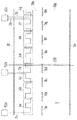
도 1 은 2 개의 레인들을 갖는 도로를 개략적으로 도시하며, 여기서 각 라인들은 미리 제조된 정형된 블록들을 사용하여 레인들 중 하나의 표면 아래에 놓여진다.
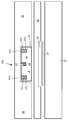
도 2 는 루트, 예를 들어 도 1 에 도시된 도로의 부분의 제 1 바람직한 실시형태를 통한 수직 단면도이다.
도 3 은 도 2 의 부분의 확대도이다.
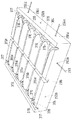
도 4 는 전기 라인들, 특히 케이블들을 지지하기 위한 지지 엘리먼트로서 사용될 수 있는 정형된 블록의 바람직한 실시형태의 사시도이다.
도 5 는 도 4 에 도시된 정형된 블록의 평면도이다.
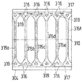
도 6 은 도 4 및 도 5 의 블록의 반절의 수직 단면도이다.
도 7 은 루트, 즉 철도 차량의 트랙의 제 2 바람직한 실시형태를 통한 수직 단면도이다.
도 8 은 철로 트랙의 제 2 제 1 실시형태의 단면도의 확대도이다.
도 9 는 전자기장을 생성하기 위해, 루트에 통합될 수도 있는 도체 배열의 연속적인 세그먼트들이다.
도 10 은 도체 배열의 2 개의 연속적인 세그먼트들의 천이 구역에서의 3 상 도체 배열의 바람직한 실시형태이며, 여기서 적어도 하나의 정형된 블록의 절삭부는 루트 내의 케이블들을 루트의 옆에서 디바이스들 및/또는 연결들로 지향시키는데 사용된다.
도 11 은 도 10 에 도시된 배열과 유사한 배열이며, 여기서 절삭부는 연속적인 세그먼트들의 3 개의 상들의 2 개의 스타 포인트 연결들을 형성하는데 사용된다.
도 12 는 이동의 방향에 대해 가로질러 연장되는 전기 라인 섹션 및 자기 코어를 포함하는 루트의 간단한 건축물을 개략적으로 도시한다.
도 13 은 일차측 및 이차측 전기 라인들을 포함하는, 에너지를 차량에 유도적으로 전달하는 시스템의 개략 측면도이다.
도 14 는 실드를 포함하는 것을 제외하고는 도 13 과 유사한 배열의 측면도이다.
도 15 는 자기 코어를 포함하는 것을 제외하고는 도 13 및 도 14 와 유사한 배열의 측면도이다.Examples and preferred embodiments of the present invention will be described with reference to the accompanying drawings.
1 schematically shows a road with two lanes, where each line is laid under the surface of one of the lanes using prefabricated shaped blocks.
2 is a vertical section through a first preferred embodiment of a route, for example the part of the road shown in FIG. 1;
3 is an enlarged view of a portion of FIG. 2.
4 is a perspective view of a preferred embodiment of a shaped block that can be used as a support element for supporting electrical lines, in particular cables.
5 is a plan view of the shaped block shown in FIG. 4.
6 is a vertical sectional view of half of the blocks of FIGS. 4 and 5.
7 is a vertical section through a second preferred embodiment of a route, ie a track of a railway vehicle.
8 is an enlarged view of a cross-sectional view of the second first embodiment of the railway track.
9 are consecutive segments of a conductor arrangement that may be integrated in the root to generate an electromagnetic field.
10 is a preferred embodiment of a three-phase conductor arrangement in the transition region of two consecutive segments of the conductor arrangement, wherein the cutting of the at least one shaped block connects the cables in the route to the devices and / or to the sides of the route. Used to direct them to the
FIG. 11 is an arrangement similar to the arrangement shown in FIG. 10 wherein the cut is used to form two star point connections of three phases of consecutive segments.
12 schematically shows a simple structure of a route comprising a magnetic core and an electric line section extending across the direction of travel.
13 is a schematic side view of a system for inductively transferring energy to a vehicle, including primary and secondary side electrical lines.
FIG. 14 is a side view of an arrangement similar to FIG. 13 except that it includes a shield;
15 is a side view of an arrangement similar to FIGS. 13 and 14 except that it includes a magnetic core.
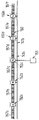
도 1 의 개략 평면도는 2 개의 레인들 (19a, 19b) 을 갖는 도로 (1) 를 도시한다. 레인들 (19) 은 외측 마진들에서 실선 (3a, 3b) 에 의해 제한되고, 라인 세그먼트들 (9a, 9b, 9c, 9d, 9e, 9f, 9g, 9h) 로 이루어지는 공통 점선에 의해 제한된다. 결과적으로, 이동의 방향은 도 1 의 좌측으로부터 우측으로 또는 우측으로부터 좌측으로 연장된다. 레인들 (19) 의 폭은 차량이 레인 (19a) 또는 레인 (19b) 중 어느 하나 상에서 이동할 수 있거나 2 개의 차량들이 레인들 (19) 상에서 서로 나란히 이동할 수 있도록 충분히 크다. The schematic top view of FIG. 1 shows a
레인들 중 하나, 즉 레인 (19a) 은 전자기장을 생성하는 도체 배열 (7a, 7b, 7c) 이 구비된다. 도체들 (7) (예를 들어, 도체 배열의 각 세그먼트에서의 3 개의 전기 위상 라인들) 및 그 도체들을 제위치에 유지하는 정형된 블록들 (4) 은, 도로를 위에서 보는 경우 비가시적이다. 그러나, 도 1 은 도체들 (7) 및 연속적인 정형된 블록들 (4a, 4b, 4c, 4d, 4e, 4f, 4g) 의 라인을 도시한다. 연속적인 정형된 블록들의 라인은 도 1 의 한계들을 너머 우측을 향해 계속된다. 도체 배열은 서로 별개로 동작될 수 있는 적어도 3 개의 연속적인 세그먼트들 (7a, 7b, 7c) 을 포함한다. 이것은, 예를 들어 도체 (7a) 는 그 세그먼트 위에서 차량이 이동하는 동안 동작되는 반면, 다른 세그먼트 (7b, 7c) 는 동작되지 않는다는 것을 의미한다. 차량들이 세그먼트 (7b) 에 도달하는 경우, 이 세그먼트는 스위치 온되고 세그먼트 (7a) 는 스위치 오프된다. 대응하는 스위치들 및/또는 인버터들은 도 1 의 상부 영역에 도시된 디바이스들 (52a, 52b, 52c) 에 통합될 수도 있다. One of the lanes,
도체들 (7) 을 놓는 바람직한 방법은 구불구불한 경로 또는 경로들을 형성하는 것이며, 이는 도체가 이동의 방향에 대해 가로질러 연장되는 섹션들을 갖는다는 것을 의미한다. 예를 들어, 도체 (7a) 는 정형된 블록 (4a) 에서 3 개의 가로질러 연장되는 섹션들, 연속적인 블록 (4b) 로의 천이 구역에서 하나의 가로질러 연장되는 섹션, 블록 (4b) 의 영역에서 3 개의 가로질러 연장되는 섹션들, 및 도체 (7a) 가 디바이스 (52b) 에 연결되는 블록 (4c) 에서 하나의 가로질러 연장되는 섹션을 갖는다. 실제로, 도체 배열의 각 세그먼트에 대해 적어도 2 개의 상들을 사용하는 것이 바람직하다. The preferred way of laying the conductors 7 is to form a serpentine path or paths, which means that the conductor has sections extending transverse to the direction of movement. For example, the conductor 7a can be arranged in three transverse sections in the shaped block 4a, one transverse section in the transition zone to the
도 1 의 중간 섹션에는, 이동의 방향에 대해 가로질러 연장되는 2 개의 평행한 라인들이 존재한다. 이들 라인들은 상대적인 이동 및/또는 열 팽창 또는 열 수축을 허용하기 위해 서로의 사이에 갭 (200) 을 갖는 루트 세그먼트들의 단부의 라인들이다. 갭 (200) 은 2 개의 연속적인 정형된 블록들 (4c, 4d) 사이에 위치되고, 도체 (7b) 는 역청과 같은 탄성적으로 변경가능한 재료로 채워질 수도 있는 갭 (200) 을 가로질러 연장된다. In the middle section of FIG. 1 there are two parallel lines extending transverse to the direction of movement. These lines are lines at the ends of the root segments with a
도 2 는 루트의 바람직한 실시형태를 통한 수직 단면도를 도시하며, 여기서 루트 상에서 이동하는 차량들의 이동의 방향은 도 2 의 이미지 평면에 수직으로 연장된다. 도 2 는 예를 들어 도 1 의 레인 (19a) 의 단면을 도시할 수도 있으며, 디바이스들 (52) 이 도시되어 있는 상부 영역에서 도 1 에 위치될 수도 있는 이머전시 레인의 단면을 도시한다. 이머전시 레인은 참조번호 29 에 의해 도 2에 표시된다. 옆으로, 이머전시 레인 (29) 의 우측에 디바이스들 (52) 중 하나가 도 2 에 도시되어 있다.2 shows a vertical cross section through a preferred embodiment of the route, wherein the direction of movement of the vehicles moving on the route extends perpendicular to the image plane of FIG. 2. FIG. 2 may, for example, show a cross section of
레인 (19a) 은 예를 들어 20 cm 의 층 두께를 가질 수도 있는 베이스층 (31) 을 포함한다. 베이스층 (31) 의 상부에는, 예를 들어 5 mm 의 두께를 갖는, (알루미늄 플레이트들과 같은) 도전성 재료의 층 (20) 이 놓여 진다. 층 (20) 의 목적은 전자기장을 차폐하는 것, 즉 층 (20) 아래의 전자기파들을 방지하거나 감소시키는 것이다. 층 (20) 은 레인 (19a) 의 폭보다 더 좁고 층 (20) 위에 배치되는 정형된 블록 (4) 의 폭의 범위에 있을 수도 있다.
차폐층 (20) 은 예를 들어 5 cm 의 두께를 가질 수도 있는 중간층 (33) 에 임베딩된다. 중간층 (33) 의 상부에는, 예를 들어 도 1 에 도시된 배열과 유사하게 구불구불한 방식으로, 전기 라인들 (17) 을 유지하기 위한 정형된 블록 (4) 이 배치된다. 블록 (4) 은 예를 들어 15 cm 의 두께를 가질 수도 있다. 블록 (4) 으로부터 중간층 (33) 의 상부 표면으로 하방으로 그리고 이머전시 레인 (29) 을 통해 옆으로 다바이스 (55) 까지의 전기 라인 (17) 의 연결이 도 2 에 도시되어 있다.The
블록 (4) 은 20 cm 의 두께를 가질 수도 있는 커버층 (35) 에 임베딩된다. 선택적으로, 상부층 (37) 은 이머전시 레인 (29) 과 레인 (19a) 의 표면을 형성하기 위해 제공될 수도 있다.The
베이스층 (31) 은 레인 (19a) 의 전체 폭에 걸쳐 연장된다. 이머전시 레인 (29) 은 동일한 재료이지만, 바람직하게는 예를 들어 8 cm 의 더 작은 두께를 갖는 베이스층 (31a) 을 가질 수도 있다. 커버층 (35) 은 레인 (19a) 의 전체 폭에 걸쳐 연장되며, 이는 커버층 (35) 이 (위에서 사용된 용어로 정형된 블록의 옆의 영역들인) 블록 (4) 의 양 측면들 상의 영역들을 갖는다는 것을 의미하며, 블록 (4) 의 옆의 커버층 (35) 의 두께가 블록 (4) 의 상부의 커버층 (35) 의 두께보다 더 크다는 것을 의미한다. 이머전시 레인 (29) 은 일정한 두께를 갖는 동일한 재료의 커버층 (35a) 을 가질 수도 있다. 그러나, 도체 (17) 을 차폐하기 위해, 전기 절연 재료, 예를 들어 (예를 들어, 1 cm 의 두께를 갖는) 알루미늄의 층 (21) 이 도체 (17) 의 연결 바로 위에 커버층 (35) 의 저부에 위치될 수도 있다. 바람직하게는 이머전시 레인 (29) 의 전체 폭들에 대해 연장되는 그러한 차폐층 (21) 에 의해, 주위로의 전자기 방출이 상당히 감소된다. 도체 배열의 세그먼트들이 차량이 세그먼트 상에서 이동하고 있는 동안에만 동작되는 경우, 차량은 도체 배열에 의해 생성되는 전자기장으로부터 주위를 차폐한다. 따라서, 이머전시 레인 (29) 과 정형된 블록 (4) 사이의 도체 (17) 의 섹션을 차폐하는 것은 사소한 개선만을 초래할 것이다.
베이스층은 모래 시멘트로 만들어질 수도 있다. 중간층 (33) 은 아스팔트로 만들어질 수도 있다. 정형된 블록 (4) 및 커버층 (35) 은 파이버 콘크리트로 만들어질 수도 있다.The base layer may be made of sand cement. The
도 3 은 도 2 에 도시된 건출물에 대응하는 레인 (19a) 의 건출물의 확대도를 도시한다. 동일한 참조 번호는 건축물의 동일한 부분들을 지칭한다.FIG. 3 shows an enlarged view of the construction of the
차폐층 (20) 이 중간층 (33) 이 생성되기 전에 제공되기 때문에, 중간층 (33) 은 차폐층 (20) 이 위치되는 리세스 (24) 를 가질 것이다.Since the
유사하게, 상방을 향하고, 전기 라인들의 섹션들 (37a, 37b, 37c) 을 포함하며, 바람직하게는 블록 (4) 의 중심 라인의 리세스 (95) 내에 자기 코어 재료 (39) 를 또한 포함하는 정형된 블록 (4) 내의 리세스들은 도 3 의 상부 영역에 개략적으로 나타낸 재료 부분들 (41a, 41b 및 42) 을 수용한다. 이들 재료 영역들은 바람직하게는 전기 라인 섹션들 (37) 또는 자기 코어 재료 (39) 와 리세스들의 벽들 사이의 모든 또는 거의 모든 나머지 개들을 채운다. Similarly, upwards, comprising
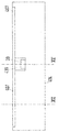
도 4 는 정형된 블록 (304) 의 사시도를 나타내고, 도 5 는 2 개의 반절들로 블록 (304) 을 분할하는 중심 라인 (310) 에 대해 수직으로 연장되는 6 개의 리세스들 (315a-315f) 을 포함하는 정형된 블록 (304) 의 평면도를 도시한다. 중신 라인 (310) 은 블록 (304) 이 차량을 위한 루트의 부분을 형성하는 경우 차량의 이동의 방향으로 연장된다. 4 shows a perspective view of a
리세스들 (315) 은 서로 평행하며, 도 5 의 평면에 평행한 동일한 수평 평면 내에 배열된다. 리세스들 (315) 은 블록 (304) 의 총 폭의 약 3/4 에 걸쳐 폭 방향 (도 5 의 수직 방향) 으로 연장된다. 그들은 중심 라인 (310) 에 대해 대칭으로 배열된다.The
각각의 리세스는 U 자 형상 단면을 가져 케이블을 수용한다. 리세스들 (315) 을 따라 연장되는 도 5 에 도시된 점선들은 리세스들 (315) 의 중심 라인들이다. 곧은 리세스들 (315) 의 2 개의 대향 단부들의 각각에는, 블록 (304) 의 측방향 에지를 따라 연장되는 주변의 곧은 리세스 (317) 로의 천이들을 형성하는 두갈래로 갈라진 만곡된 리세스 영역들 (316) 이 존재한다. 케이블들은 곧은 리세스들 (315) 로부터 만곡된 리세스 영역 (316) 을 통해 주변의 곧은 리세스 (317) 로 연속적으로 연장되는 방식으로 놓여질 수 있고, 이로 인해 이동의 방향에 대해 수직으로 이동의 방향에 대해 평행으로 연장의 방향을 변경한다. 전기 라인들 (예를 들어, 케이블들) 의 배열들의 예들이 도 10 및 도 11 에 도시되어 있으며, 후술될 것이다. Each recess has a U-shaped cross section to accommodate the cable. The dotted lines shown in FIG. 5 extending along the
만곡된 리세스 영역들 (316) 은 리세스 (315) 의 곧은 방향에서 보는 경우, 좌측 또는 우측으로 계속되는 방식으로, 리세스 (315) 를 통해 연장되는 케이블을 배치하는 것을 허용한다. 예를 들어, 케이블 (도 4 및 도 5 에는 도시되지 않음) 은 리세스 (315b) 를 통해 연장될 수도 있고, (리세스 영역 (316) 을 통해 연장하는 동안) 우측으로 터닝할 수도 있으며, 그 후 만곡된 리세스 영역 (316) 의 대향 측상의 리세스들 (315) 에 대해 수직으로 연장되는 곧은 리세스 (317) 을 통해 연장될 수도 있다. 블록 (304) 의 대향 측들 상에는 2 개의 주변의 곧은 리세스들 (317) 이 존재한다. 케이블은 그 후 리세스 (315e) 를 통해 연장될 수도 있다. 도 5 의 하부에 도시되어 있는 리세스 (315a) 의 단부에서,케이블은 다시 리세스 영역 (316) 을 통해 다른 곧은 리세스 (317) 로 다시 터닝할 수도 있다. 다른 리세스들 (315) 은 2 개의 다른 케이블들을 위해 사용될 수도 있다.The
도 6 에 도시된 바와 같이, 리세스들 (315, 316, 317) 의 깊이는 상이하다. 리세스 (315) 의 깊이는 하나의 케이블을 수용하기에 충분하다. 만곡된 리세스 영역 (316) 의 깊이는 도 6 의 점선에 의해 표시된 바와 같이 리세스 (315) 의 단부로부터 리세스 (317) 로 증가한다. 만곡된 리세스 영역 (316) 의 저부 프로파일은, 단면도가 리세스되지 않은 블록 (304) 의 영역 (319) 을 포함하기 때문에, 도 6 에 완전히 도시되지 않는다. 만곡된 리세스 영역들 (316) 각각은 만곡된 리세스 영역 (316) 의 2 개의 만곡된 브랜치들 사이에 위치되는 그러한 아일랜드 영역 (319) 을 포함한다. 브랜치들 중 하나는 도 6 의 평면 위에서 연장되고, 다른 브랜치는 도 6 의 평면 아래에서 연장된다. 또, 아일랜드 영역 (319) 은 곧은 리세스 (317) 와 만곡된 리세스 영역 (316) 의 2 개의 브랜치들 사이에 위치된다.As shown in FIG. 6, the depths of the
만곡된 리세스 영역 (316) 의 깊이가 곧은 리세스 (317) 를 향하여 증가하기 때문에, 상이한 케이블들이 서로의 위에 놓여질 수 있다. 곧은 리세스 (317) 의 깊이는 동일한 곧은 방향으로 연장되는 서로의 위에 2 개의 케이블들을 정렬하는데 충분하다. 예를 들어, 제 1 케이블은 도 5 의 더 낮은 리세스 (317) 를 통해 연장될 수도 있고, 도 5 의 저부 좌측부에 도시된 리세스 영역 (316) 을 통해 리세스 (315b) 로 좌측으로 터닝할 수도 있다. 또, 제 2 케이블은 리세스 (315a) 를 통해 연장될 수도 있고, 리세스 (317) 로 터닝할 수도 있으며, 이로 인해 제 1 케이블을 (위에서 보는 경우) 교차한다. Since the depth of the
위에 주어진 케이블들 또는 전기 라인들의 연장에 관한 예는 4 개의 구불구불한 케이블들을 놓기 위한 하나의 특정의 애플리케이션을 지칭한다. 그러나, 도 4 내지 도 6 에 도시된 정형된 블록 (304) 의 사용은 이러한 애플리케이션에 제한되지 않는다. 오히려, 예를 들어, 3 개보다 더 적거나 더 많은 케이블들이 도 5 및 도 6 에 도시된 블록 (304) 를 사용하여 놓여질 수 있다.The example of extension of the cables or electrical lines given above refers to one particular application for laying four winding cables. However, the use of the shaped
도 4 에 도시된 블록 (304) 의 측 표면들은 리세스들, 특히 보어들 (290a, 290b, 292a, 292b, 290c) 을 포함한다. 다른 리세스들은 도 4 에서 가시적이지 않은 측 표면들에 위치된다. 도시된 예에서, (도 4 의 우측 상의) 이동의 방향으로 연장되는 측 표면은 3 개의 리세스들 (292a, 292b, 292c) 을 포함한다. 모든 리세스들 (292) 은 앵커 (294a, 294c) 를 포함하고, 여기서 앵커 또는 리세스 (292b) 는 도시되지 않는다. 앵커들 (294) 은 측 표면으로부터 돌출부들로서 연장된다. 커버층이 304 의 옆의 영역들을 채우도록 제공되는 경우, 앵커들 (294) 은 커버층의 재료에 의해 임베딩된다. The side surfaces of the
이동의 방향으로 대향하는 측 표면의 리세스들 (290a, 290b) 은 또한 앵커들 (291) 을 포함하며, 여기서 리세스 (290a) 의 앵커는 도 4 에 도시되지 않는다. 이들 앵커들은 이웃하는 블록 (도 4 에 도시되지 않음) 이 측 표면 근처에 배치되기 전에 리세스들 (290) 내에 고정된다. 이웃하는 블록은 블록 (304) 의 측 표면을 향해 이동되어, 앵커들 (291) 이 이웃하는 블록의 대응하는 리세스들에 삽입되도록 한다. 그 후, 또는 바로 전에, 충전 재료 (filling material) 가 이웃하는 블록의 대응하는 리세스들에 도입되어 앵커들 (291) 과 대응하는 리세스들 사이의 갭들을 채운다. 충전 재료는 2-성분 접착제일 수도 있다.
도 7 은 철도 차량을 위한 트랙의 건축물을 통한 단면도를 도시한다. 도 8 은 철도 차량을 위한 트랙의 변경된 건출물을 통한 확대 단면도를 도시한다. 양 도면에서, 서로 평행하게 연장되는 2 개의 레일들은 303a, 303b 로 표시된다. 레일들 (303) 사이에서, 블록 (304) 은 케이블들을 수용하기 위해 배치된다. 블록 (304) 은 도 4 의 미리 제조된 정형된 블록일 수도 있다. 도 7 및 도 8 에 도시된 실시형태들은 도 8 에서는 직사각형이고 도 7 에서는 U자 형상인 베이스층 (10) 에 대해 상이하다. 또한, 도 7 은 언더그라운드 (35) 를 도시한다. 또한, 도 7 은 트랙의 양측면들 상의 그라운드 (12) 의 2 개의 부분들을 도시한다. 도 7 및 도 8 에 따른 루트 건축물의 공통 부분들 및 엘리먼트들은 동일한 참조 번호들을 사용하여 이하에 기술될 것이다. 예를 들어, 자기 코어에 대한 차이들은 강조될 것이다.7 shows a sectional view through a building of a track for a railroad car. 8 shows an enlarged cross sectional view through a modified building of a track for a railway vehicle. In both figures, two rails extending parallel to each other are denoted by 303a, 303b. Between the rails 303, a
(복수의 엘리먼트들로 이루어지는) 미리 제조된 트랙 모듈의 배치를 준비하기 위해, 언더그라운드는 콘크리트의 베이스층 (10) 을 포함한다. 또한, 베이스층 (10) 의 양 대향 측면들 상에는, 도관들 (361) 이 놓여진다 (도 8 에 만 도시됨). 특히, 이들 도관들 (361) 은 트랙 모듈의 전기 및 전자 디바이스들을 연결하기 위한 전기 연결 케이블들을 배치하는데 사용된다. 이들 케이블들은 예를 들어 캐비티 (cavity) 에서 트랙의 옆에 위치된 인버터들을 연결하는 전력 공급 라인의 부분들이다. In order to prepare for the arrangement of the prefabricated track module (composed of a plurality of elements), the underground comprises a
도 8 에 도시된 모든 다른 부분들은 미리 제조된 트랙 모듈의 상부 표면 상에 놓여지는 브릭층 (brick layer) (340) 을 제외하고 미리 제조된 트랙 모듈의 부분들이다. 브릭층 (340) 은 레일들 (303) 및 다른 부분들이 위치되는 미리 제조된 트랙 모듈의 중앙 영역의 양 측면들 상에 연장된다. 브릭층 (340) 은 트랙 건축물의 거의 수평으로 연장되는 표면을 형성하도록 작용한다 (도 7 참조). 브릭층 대신에, 그라운드 (12) 와 트랙 모듈의 중앙 부분 사이의 갭이 콘크리트와 같은 다른 재료로 채워질 수 있다. All other parts shown in FIG. 8 are parts of the prefabricated track module except for a
도 8 및 도 7 에 도시되어 있는 트랙 모듈의 실시형태는 바람직하게는 콘크리트로 제조된 U 자 형상 저부층 (15) 을 포함한다. 종래의 콘크리트, 플라스틱 재료를 포함하는 콘크리트 및 섬유 보강 콘크리트와 같은 임의의 종류의 콘트리트 재료가 사용될 수도 있다. 특히, 콘크리트는 종래의 금속 메시들에 의해 장갑될 수도 있다. 그러나, 보강을 위한 섬유 입자들을 포함하고 플라스틱 엘리먼트들을 포함하는 경량 콘크리트를 사용하는 것이 바람직하다. 그러한 콘크리트 재료는 트랙 상을 이동하는 임의의 철도 차량에 의해 야기된 진동들이 감쇠되는 다른 이점을 갖는다. The embodiment of the track module shown in FIGS. 8 and 7 preferably comprises a U-shaped
U 자 형상 저부층 (15) 은 U 의 2 개의 아암들 사이에 절삭 영역에 위치되는 트랙 모듈의 중앙 영역을 정의한다. 이러한 중앙 절삭 영역은 상부에 대해 개방되고 저부로부터 상부로 진동들의 추가의 댐핑을 위한 엘라스토머 재료로 제조된 층 (345), 차폐 엘리먼트 (355), (도 8 및 도 7 에 도시되지 않은) 도체 배열을 지지하는 지지 엘리먼트 (304) 및 고무로 제조된 커버 (351) 를 포함한다. The U-shaped
층 (345) 은 트랙 모듈의 중앙 영역의 전체 길이에 걸쳐 수평 방향으로 연장된다. 중앙 영역들의 측면 마진들의 영역들에서, 2 개의 레일들 (303a, 303b) 은 층 (345) 의 상부 상에 배치된다. 본 기술에서 원칙적으로 알려져 있는 바와 같이, 레일들 (303) 은 바람직하게는 폴리우레탄과 같은 플라스틱 재료로 제조된 내측 및 외측 고정 엘리먼트들 (335, 336) 을 사용하여 제위치에 유지된다. 지지 엘리먼트 (304) 는 리세스들 (315, 317) 을 포함하고 도 1 내지 도 5 에 도시된 바와 같이 구성될 수도 있다. 지지 엘리먼트 (304) 는 내측 고정 엘리먼트들 (336) 사이에 타이트하게 끼워맞춰진다.
지지 엘리먼트 (304) 아래에, 도체 배열에 의해 생성된 전자기장들을 차폐하는 실드 (355) 가 슈들 (shoes) (299a, 299b) 사이에 연장되며, 이것에 의해 슈들 (336) 을 전기적으로 접촉시킨다. 대안적인 실시형태에서, 실드는 레일들 중 단지 하나에 연결될 수도 있다. 이러한 실시형태는, 차량이 2 개의 레일들을 전기적으로 연결하고 있는 효과를 사용하여 트랙이 차량 검출 시스템과 결합되는 경우 사용된다. Under the
커버 (351) 는 2 개의 레일들 (303) 의 상부 부분들 사이에 연장되고, 지지 엘리먼트 (304) 와 레일 (303) 사이의 그루브들 내로 하향하여 돌출함으로써 기계적으로 고정된다. 도 8 에 도시된 것 외에, 부분들 (15, 345, 355, 335, 336, 304 및 351) 을 포함하는 (그리고 선택적으로 도체 배열과 같은 다른 부분들을 포함하는) 미리 제조된 트랙 모듈은 먼저 제조되고, 그 후 베이스층 (10) 의 상부 상에 위치된다. 그러나, 트랙 모듈의 상이한 부분들은, 예를 들어 도체 배열을 리세스들 (315, 317) 내로 배치하기 위한 커버 (351) 는 현장에서 제거될 수 있다. 도체 배열을 놓은 후, 커버는 다시 제위치에 놓여질 수 있다. 이전에 언급된 바와 같이, 도체 배열은 대안적으로 미리 제조된 트랙 모듈의 일부일 수 있어서, 유지보수 및 수리를 제외하고는 커버 (351) 을 제거할 필요가 없도록 한다.The
바람직하게는, 도체 배열은, 도체 배열의 라인들 또는 와이어들이 리세스들의 에지들의 높이 레벨 위로 돌출하지 않는 방식으로 지지 엘리먼트의 리세스들 내에 배치된다. 따라서, 지지 엘리먼트를 향하고 있는 거의 평면인 표면을 갖는 커버는 지지 엘리먼트의 최대 가능한 상부 표면 상에 안착할 수 있다.Preferably, the conductor arrangement is arranged in the recesses of the support element in such a way that the lines or wires of the conductor arrangement do not protrude above the height level of the edges of the recesses. Thus, a cover having a nearly planar surface facing the support element can rest on the maximum possible top surface of the support element.
도 7 에 도시된 건출물은 실드 (355) 와 정형된 모듈 (304) 사이에 배치되는 중간층 (341) 의 하측면상의 리세스 (339) 를 포함한다. 도 8 에 도시된 건축물과는 대조적으로, 도 7 의 정형된 모듈 (304) 은 실드 (355) 까지 연장되지 않고, 중간층 (341) 에 의해 실드 (355) 로부터 분리된다. The construct shown in FIG. 7 includes a
도 7 에 도시된 건축물에 대안적으로, 리세스 (339) 가 중간층 (341) 의 상부측 상에 위치될 수도 있고, 및/또는 도 8 에 도시된 건축물과 유사하게 정형된 모듈 (304) 의 하측면상에 위치될 수도 있다. 그러나, 도 8 의 정형된 모듈 (304) 은 실드 (355) 에 대해 수직 방향으로 연장되며, 즉 정형된 모듈 (304) 과 실드 (355) 사이에 중간층이 존재하지 않는다. 도 8 에 도시된 건축물 내의 자기 코어를 위한 리세스는 참조 번호 (349) 에 의해 표시된다.Alternatively to the architecture shown in FIG. 7, a
도 7 및 도 8 에 도시된 리세스들 (339, 349) 은 도면들의 이미지 평면에 수직인 이동의 방향으로 연장된다. 수직 방향에 대한 리세스 (339, 349) 의 적어도 일부는 도 12 에 도시된 개략도와 유사하게 자기 코어 재료 (도 7 및 도 8 에는 도시하지 않음) 로 채워진다. 그러나, 도 12 는 리세스 (439) 가 정형된 블록 또는 재료층 (404) 의 상측 상에 제공되고, 따라서 상부를 향해 개방되어 있는 변형을 도시한다. 루트의 건설 동안, 리세스 (439) 는 소정의 미리 정의된 높이 까지 자기 코어 재료 (39) 로 채워질 것이고, 그 후 일차측 도체 배열의 라인 또는 라인들이 놓여진다. 이동의 방향 (이동의 방향은 도 12 의 이미지 평면에 수직이다) 에 대해 가로질러 연장되는 하나의 라인 섹션 (407) 이 도 12 에 도시된다. 실드 (도 12 에 도시하지 않음) 는 정형된 모듈 또는 재료층 (404) 의 저부 표면에 위치될 수도 있거나 더 아래에 위치될 수도 있다.The
도 7 에 도시된 실시형태에서, 실드 (355) 가 먼저 놓이고, 그 후 리세스 (339) 내에 자기 코어 재료를 이미 포함하고 있는 미리 제조된 중간층 (341) 이 실드 (355) 의 상부 상에 배치된다. 예를 들어, 자기 코어 재료는 접착제를 사용하여 중간층 모듈 (341) 에 고정될 수도 있다. 대안적으로, 자기 코어 재료는 실드 (355) 의 상부측 상에 먼저 배치될 수도 있고, 그 후 중간층 (341) 이 콘크리트와 같은 넌-솔리드 (non-solid) 원자재로부터 생성될 수도 있다. In the embodiment shown in FIG. 7, the
도 8 에 도시된 건축물에서의 자기 코어의 생성은 도 7 에 도시된 건축물에 대해 전에 설명된 바와 동일한 방식으로 수행될 수도 있다. 그러나, 자기 코어 재료가 실드 (355) 의 상부 상에 정형된 모듈 (304) 을 배치하기 전에 정형된 모듈 (304) 에 고정되거나, 배열의 상부 상에 정형된 모듈 (304) 을 배치하기 전에 실드 (355) 의 상부 상에 먼저 배치되도록, 도 8 에는 중간층이 존재하지 않는다.The generation of the magnetic core in the building shown in FIG. 8 may be performed in the same manner as previously described for the building shown in FIG. 7. However, the magnetic core material is fixed to the shaped
도 9 는 차량 (도시하지 않음) 의 이동의 경로을 따라 (우로부터 좌로 또는 그역으로) 연장되는 도체 배열의 6 개의 세그먼트들 (157a 내지 157f) 을 도시한다. 세그먼트들 (157) 은 서로 독립적으로 동작될 수 있다. 그들은 전기적으로 서로 병렬로 연결된다. 차량은 세그먼트들 (157) 중 하나의 세그먼트 또는 하나 보다 많은 세그먼트들에 의해 생성되는 전자기장을 수신하는 수신 디바이스를 포함할 수도 있다. 예를 들어, 차량의 수신 디바이스가 세그먼트 (157c) 위에 위치되는 경우, 적어도 이러한 세그먼트 (157c) 는 전자기장을 생성하고 차량에 에너지를 제공하도록 동작된다. 또한, 차량은 충분하지 않은 에너지가 세그먼트들 (157) 로부터 수신되는 경우 차량을 동작시키는데 사용될 수도 있는 에너지 저장장치를 포함할 수도 있다. 9 shows six segments 157a-157f of conductor arrangement extending along the path of movement of a vehicle (not shown) (from right to left or vice versa). Segments 157 may be operated independently of each other. They are electrically connected in parallel to each other. The vehicle may include a receiving device that receives an electromagnetic field generated by one or more than one of the segments 157. For example, if the receiving device of the vehicle is located above the
2 개의 연속적인 세그먼트들 (157) 사이의 각 인터페이스에는, 캐비티 내에, 바람직하게는 루트의 옆의 그라운드 내에 배치되는 인버터 (152a 내지 152e) 가 제공된다. DC (직류) 전력 공급 라인 (141a, 141b) 이 또한 도 9 에 도시되어 있다. 그것은 직류를 생성하는 발전소와 같은 에너지 소스 (51) 에 연결된다.Each interface between two successive segments 157 is provided with inverters 152a to 152e disposed in the cavity, preferably in the ground next to the route. DC (direct current) power supply lines 141a, 141b are also shown in FIG. It is connected to an energy source 51, such as a power plant generating direct current.
도 10 은 트랙으로 및/또는 트랙으로부터 전도하는 라인들을 위한 영역 (609) 이 존재하는 것을 제외하고, 도 4 에 도시된 종류의 정형된 블록들 (304) 에 의해 정의될 수도 있는 트랙 또는 트랙의 부분의 외측 한계들 (504) 을 점섬으로 도시한다. 예를 들어, 영역 (609) 은 블록의 일측면에서 절삭부 (341) 내에 위치될 수도 있다. 그러한 절삭부는 블록들에 의해 제위치에 유지되는 전기 라인들로 이루어지는 도체 배열을 완성하는 것을 용이하게 한다.FIG. 10 illustrates a track or track of which may be defined by shaped
도 10 에 도시된 도체 배열은 3상 도체 배열이며, 즉 도 10 에 도시된 도체 배열의 2 개의 세그먼트들 각각은 3상 교류 전류의 3 개의 상들을 전도시키는 3 개의 위상 라인들 (507a, 507b, 507c; 508a, 508b, 508c) 을 포함한다. 3개의 상들 중 하나의 상 (507a, 508a) 은 단일 라인으로 표시되고, 3개의 상들 중 두번째 상 (507b, 508b) 은 이중 라인으로 표시되며, 3개의 상들 중 세번째 상 (507c, 508c) 은 삼중 라인으로 표시된다. 모든 전기 라인들은 이동의 방향 (좌측으로부터 우측으로 또는 그 역으로) 으로 구불구불한 방식으로 연장되어 있다. 도 10 에 도시된 영역은 도체 배열의 2 개의 연속적인 세그먼트들의 천이 영역이다. 각 세그먼트는 서로 개별적으로 동작될 수 있지만, 세그먼트들은 또한 동시에 동작될 수 있다. 도 10 은 기본 개념, 즉 연속적인 세그먼트들의 중첩하는 영역들의 개념의 바람직한 실시형태를 도시한다. 바람직하게는, 실드 (도시하지 않음, 예를 들어 도 10 의 이미지 평면에 평행하게 위치됨) 는 점선들 (504) 에 의해 경계가 지어지는 영역, 영역 (609), 및 라인들 (507, 508) 이 트랙 또는 루트의 옆에서 디바이스들로 안내되는 영역을 커버한다. The conductor arrangement shown in FIG. 10 is a three-phase conductor arrangement, ie each of the two segments of the conductor arrangement shown in FIG. 10 has three
아래에 기술되는 구불구불한 3상 도체 배열은 또한, 외부 디바이스들로의 연결이 상이한 방식으로 행해지는 경우 실현될 수 있다. 도 10 의 좌측에 도시된 세그먼트는 위상 라인들 (507a, 507b, 507c) 을 포함한다. 이들 위상 라인들 (507) 의 연장을 좌측에서 우측으로 따르는 경우, 절삭 영역 (609) 에 도달하는 각 위상 라인 (507) 은 위상 라인들 (507) 을 동작시키는 임의의 디바이스 (도시하지 않음) 를 향해 정형된 블록들의 연속적인 라인으로부터 멀리 안내된다. 예를 들어, 위상 라인 (507b) 은 절삭부 (609) 에 도달하고, 여기서 절삭부 (609) 는 종료한다. 위상 라인 (507b) 과는 대조적으로, 위상 라인들 (507a, 507c) 은 절삭부 (609) 를 향하는 정형된 블록들의 라인의 반대측으로부터 연장되는 라인 섹션을 갖는 절삭부 (609) 에 도달한다. The serpentine three-phase conductor arrangement described below can also be realized when the connection to external devices is done in a different way. The segment shown on the left of FIG. 10 includes
3 개의 위상 라인들 (507) 각각은 이동의 방향에 대해 가로질러 연장되는 라인 섹션들을 포함한다. 이들 가로질러 연장되는 섹션들은 이동의 방향에서 위상들의 반복하는 시퀀스를 형성하며, 즉 제 1 위상 라인 (507a) 의 섹션을 제 2 위상 라인 (507b) 의 섹션이 뒤따르고, 제 2 위상 라인 (507b) 의 섹션을 제 3 위상 라인 (507c) 의 라인 섹션이 뒤따르는 등등이다. 위상 라인들의 이러한 반복된 시퀀스로 계속하기 위해, 이웃하는 세그먼트의 위상 라인 (508b) (제 2 위상 라인) 이 절삭 영역 (609) 를 통해 안내되어, 다른 세그먼트의 제 1 위상 라인 (507a) 과 제 3 위상 라인 (507c) 사이에서 가로질러 연장되는 라인 섹션을 형성하며, 여기에서 이들은 영역 (609) 에 도달한다. 즉, 제 2 세그먼트의 제 2 위상 라인 (508b) 은 제 1 세그먼트의 제 2 위상 라인 (507b) 을 대체하여 위상 라인들의 반복되는 시퀀스로 계속된다. 제 2 세그먼트의 다른 위상 라인들, 즉 제 1 위상 라인 (508a) 및 제 3 위상 라인 (508c) 은 대응하는 방식으로 절삭 영역 (609) 을 통해 안내되어, 이동의 방향으로의 연장이 고려되는 경우 위상들의 시퀀스가 도 10 의 좌측의 제 1 세그먼트에 대한 것과 동일하도록 한다. Each of the three phase lines 507 includes line sections extending across the direction of travel. These transverse sections form a repeating sequence of phases in the direction of movement, that is, the section of the first phase line 507a is followed by the section of the
도 11 은 영역 (609) 이 상이한 목적을 위해 사용되는 유사한 배열을 도시한다. 도 10 및 도 11 에서 동일한 참조 번호들이 동일한 특징들 및 엘리먼트들을 지칭한다.11 shows a similar arrangement in which
도 11 은 2 개의 연속적인 세그먼트들, 예를 들어 도 10 의 우측 상에 도시된 세그먼트 및 도체 배열의 다른 세그먼트의 천이 영역을 도시한다. 이러한 다른 세그먼트의 위상 라인들은 그 다른 세그먼트의 509a (제 1 위상 라인), 509b (제 2 위상 라인), 및 509c (제 3 위상 라인) 에 의해 표시된다. 도 11 에 도시된 실시형태에서, 절삭부 (609) 는 각 세그먼트의 3 개의 상들 사이에 전기 연결들을 확립하기 위한 영역으로서 사용되며, 즉 스타 포인트 연결이 각 세그먼트에 대해 행해진다. 스타 포인트들은 511a 또는 511b 로 표시된다. 바람직하게는, 스타 포인트 (511) 의 위치는 위상 라인들의 라인 섹션들 보다 커버층의 상부 표면까지 더 큰 거리에 있으며, 여기서 위상 라인들은 정형된 블록들에 의해 정의되는 리세스들 또는 스페이스들 내에 위치된다. 따라서, 스타 포인트 연결들은 잘 보호된다. FIG. 11 shows the transition region of two consecutive segments, for example the segment shown on the right side of FIG. 10 and another segment of the conductor arrangement. The phase lines of this other segment are represented by 509a (first phase line), 509b (second phase line), and 509c (third phase line) of that other segment. In the embodiment shown in FIG. 11, the
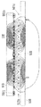
도 13 내지 도 15 는 일차측 및 이차측 전기 라인들을 포함하는, 차량에 에너지를 유도적으로 전달하는 시스템의 개략 측면도를 도시한다. 일차측 라인들은 작은 사각형들 (501a - 501o) 로서 도시된다. 이들 사각형들은 3 상 도체 배열의, 예를 들어 도 10 및 도 11 에 도시된 배열의 전기 라인들의 가로질러 연장되는 라인 섹션들의 단면들을 상징한다. 이들 가로질러 연장되는 라인 섹션들 (501) 은 교류 전자기장을 생성하며, 특히 이동 방향으로 또는 이동 방향에 대해 반대로 이동하는 자기파를 생성한다. 이동 방향은 도 13 내지 도 15 에서 좌측에서 우측으로 또는 우측에서 좌측으로 연장된다.13-15 show schematic side views of a system for inductively delivering energy to a vehicle, including primary and secondary side electrical lines. The primary side lines are shown as
도 13 내지 도 15 의 더 높은 위치에, 차량의 이차측 배열의 도체들이 도시되고, 502a - 502i 에 의해 표시된다. 이들 이차측 도체들은 또한 이동의 방향에 대해 가로질러 연장된다. 이차측 도체들 (502) 의 상부 상에는, 자기 코어 재료의 층 (510) 이 존재한다. 그러나, 코어 (510) 의 높이는 자속선들의 경로를 보여주기 위해 스케일대로 도시되지 않는다. 동일한 것이 도 14 및 도 15 의 자기 코어들 (510, 530) 에 적용된다. 모든 이들 자기 코어들은 바람직하게는 일차측 및 이차측 도체들의 수직 연장 및 이들 도체들 사이의 수직 거리들에 비해 수직 방향에서 더 작다.In the higher position of FIGS. 13-15, the conductors of the secondary side arrangement of the vehicle are shown and indicated by 502a-502i. These secondary conductors also extend across the direction of travel. On top of the secondary side conductors 502, there is a
도 13 내지 도 15 는 또한 자속선들 (즉, 도면들에서 도시된 단면들의 3개의 상이한 구성들 및/또는 위치들에 대해 일차측 도체들 (501) 에 의해 생성되는 자기장의 필드 라인들) 을 도시한다. 13-15 also show magnetic flux lines (ie, field lines of the magnetic field generated by the primary side conductors 501 for three different configurations and / or locations of the cross sections shown in the figures). do.
도 13 은 일차측 도체들 (501) 아래에 도전성 재료의 실드가 존재하지 않고 일차측 도체들 (501) 아래 또는 일차측 도체들 (501) 에 자기 코어 재료가 존재하지 않는 구성을 도시한다. 결과적으로, 플럭스 라인들은 일차측 도체 배열 아래의 영역들에 깊이 침투한다. FIG. 13 shows a configuration in which there is no shield of conductive material below the primary side conductors 501 and no magnetic core material exists below the primary side conductors 501 or in the primary side conductors 501. As a result, the flux lines penetrate deeply into the areas under the primary side conductor arrangement.
도 14 는 일차측 도체들 (501) 아래에 도전성 재료의 실드 (520) 가 존재하는 구성을 도시한다. 실드 (520) 는 거의 완전히 실드 (520) 를 통한 자기장 라인들의 침투를 방지한다. 결과적으로, 필드 라인들은 실드 (520) 위에서 우회되어, 그들이 실드 (520) 와 이차측 도체 배열 (502) 사이에서 거의 수평으로 연장된다. 그러나, 실드 (520) 내의 와전류들에 의해 야기된 에너지 손실들로 인해, 이차측 도체 배열의 자속은 감소된다. 14 shows a configuration in which a
도 15 에 도시된 구성은 도 14 에 도시된 구성의 실드 (520) 대신에 자기 코어 재료 (530) 의 층 또는 라인을 포함한다. 자기 코어 재료 (530) 의 수직 위치는 도 14 의 실드 (520) 의 수직 위치보다 약간 더 높다. The configuration shown in FIG. 15 includes a layer or line of
자기 코어 재료 (530) 의 효과는 자기장 라인들이 자기 코어 재료 (530) 로 끌려지며, 즉 자기 코어 재료 (530) 에 거의 수직으로 연장되지만, 자기 코어 재료 (530) 에 의해 재지향되어 층 또는 라인의 수평 연장을 뒤따른다는 것이다. 또한, 자기 코어 재료 (530) 는 이차측 도체 배열에서 자속을 증가시킨다. The effect of the
도 12 에 도시된 구성으로 되돌아 가서, 수평으로, 즉 가로질러 연장되는 라인 섹션 (407) 에 평행하게 연장되는 자기 코어 재료 (39) 아래에 추가적인 실드가 존재하지 않는다면, 도 15 에 도시된 구성은 도 12 의 점선 XIV 에 의해 나타낸 단면에 대응한다. 즉, 도 14 에 도시된 단면은 점선 XIV 에서 도 12 의 이미지 평면에 대해 수직으로 연장될 것이다. 유사하게, 도 15 에 도시된 단면은 자기 코어 (39) 와 교차하는 점선 XV 에서 도 12 의 이미지 평면에 대해 수직으로 연장될 것이다. 이것은 도 14 에 도시된 구성 및 도 14 에 도시된 결과적인 자속선들이 도 12 의 점선 XIV 의 영역에서의 상황을 근사적으로 나타낸다는 것과 도 15 에 도시된 구성 및 자속선들이 도 12 의 점선 XV 에서의 상황을 나타낸다는 것을 의미한다. 도전성 재료의 실드가 도 15 에 도시된 상황에 영향을 미치지 않는 이유는 자기 코어 재료가 자속선들을 끌어당기고 재지향시킨다는 것이다. 그러나, 자기 코어 재료의 작은 두께로 인해, 비교적 작은 자속은 자기 코어 재료 (530) 아래의 하나의 자속선에 의해 도 15 에 도시된 바와 같이 자기 코어 재료 바로 아래에서도 효과적이다. Returning to the configuration shown in FIG. 12, if there is no additional shield under the
이차측 도체 배열에서의 자기장에 의해 야기되는 유도가 가로질러 연장되는 라인 섹션들의 길이에 걸쳐 (즉, 도 12 에서 좌로부터 우로) 적분되는 경우, 자기 코어 및 실드가 적절하게 구성된다면, 총 유도 및 결과적인 전류는 일차측에 실드 및 자기 코어가 없는 대응하는 상황에 대응할 수도 있다. 실드는 자속을 감소시키지만, 실드 아래의 거의 전체 영역을 차폐하고, 자기 코어 재료는 도 12 에 도시된 단면의 중앙 영역에서 자속을 증가시킨다. 즉, 실드는 자기 코어 재료의 요구되는 양을 감소시키는 것을 돕고, 실드의 플럭스 약화 효과는 자기 코어 재료에 의해 보상된다.If the induction caused by the magnetic field in the secondary conductor arrangement is integrated over the length of the line sections extending across (ie, from left to right in FIG. 12), if the magnetic core and shield are properly configured, total induction and The resulting current may correspond to a corresponding situation where there is no shield and magnetic core on the primary side. The shield reduces the magnetic flux, but shields almost the entire area under the shield, and the magnetic core material increases the magnetic flux in the central region of the cross section shown in FIG. That is, the shield helps to reduce the required amount of magnetic core material, and the flux weakening effect of the shield is compensated by the magnetic core material.
Claims (10)
상기 시스템은, 자기장을 생성하고, 이것에 의해 상기 차량에 에너지를 전달하는 전기 도체 배열 (7) 을 포함하며,
상기 전기 도체 배열 (7) 은 적어도 하나의 전류 라인 (507, 508, 509) 을 포함하고, 각각의 전류 라인 (507, 508, 509) 은 상기 자기장을 생성하는 전류를 반송하도록 구성되거나, 상기 자기장을 생성하는 병렬 전류들 중 하나를 반송하도록 구성되며,
- 상기 전류 라인 또는 라인들 (507, 508, 509) 은 제 1 높이 레벨에서 연장되고,
- 상기 시스템은 상기 자기장을 차폐하는 도전성 실드 (20; 355; 520) 로서, 트랙 아래에서 연장되고, 상기 제 1 높이 레벨 아래에서 연장되는, 상기 실드 (20; 355; 520) 를 포함하며,
- 자기 코어 (39) 가 제 2 높이 레벨에서 상기 트랙을 따라 연장되고, 상기 실드 (20; 355; 520) 위에서 연장되는, 차량에 전기 에너지를 전달하는 시스템.A system for delivering electrical energy to vehicles, especially track bound vehicles such as road cars or light rail vehicles,
The system comprises an electrical conductor array 7 which generates a magnetic field and thereby transfers energy to the vehicle,
The electrical conductor arrangement 7 comprises at least one current line 507, 508, 509, each current line 507, 508, 509 being configured to carry a current which generates the magnetic field, or the magnetic field Is configured to carry one of the parallel currents generating
The current line or lines 507, 508, 509 extend at a first height level,
The system comprises a conductive shield (20; 355; 520) shielding the magnetic field, the shield (20; 355; 520) extending below the track and extending below the first height level;
A magnetic core (39) extends along the track at a second height level and extends above the shield (20; 355; 520).
상기 자기 코어 (39) 가 연장되는 상기 제 2 높이 레벨은 상기 제 1 높이 레벨 아래에 있고,
상기 자기 코어 (39) 는 상기 실드 (20; 355; 520) 와 상기 전류 라인 또는 라인들 (507, 508, 509) 사이에 연장되는, 차량에 전기 에너지를 전달하는 시스템.The method of claim 1,
The second height level from which the magnetic core 39 extends is below the first height level,
The magnetic core (39) extends between the shield (20; 355; 520) and the current line or lines (507, 508, 509).
상기 자기 코어 (39) 는 이동의 방향으로 연장되는, 차량에 전기 에너지를 전달하는 시스템.3. The method according to claim 1 or 2,
The magnetic core (39) extends in the direction of movement, the system for delivering electrical energy to the vehicle.
상기 자기 코어 (39) 의 재료는 그 재료를 반송하도록 그리고 상기 전류 라인 또는 라인들을 고정하도록 구성된 미리 제조된 모듈들의 그루브들 및/또는 리세스들에 배치되는, 차량에 전기 에너지를 전달하는 시스템.The method according to any one of claims 1 to 3,
The material of the magnetic core (39) is disposed in grooves and / or recesses of prefabricated modules configured to carry the material and to fix the current line or lines.
상기 전류 라인 또는 라인들 (507, 508, 509) 은 상기 제 1 높이 레벨에서 이동의 방향에 대해 가로질러 연장되는 복수의 라인 섹션들 (407) 을 포함하는, 차량에 전기 에너지를 전달하는 시스템.The method according to any one of claims 1 to 4,
The current line or lines (507, 508, 509) comprise a plurality of line sections (407) extending transverse to the direction of movement at the first height level.
자기장을 생성하고, 이것에 의해 상기 차량 (81; 92) 에 에너지를 전달하는 전기 도체 배열 (7) 이 제공되며,
상기 전기 도체 배열 (7) 에는 적어도 하나의 전류 라인 (507, 508, 509) 이 제공되고, 각각의 전류 라인 (507, 508, 509) 은 상기 자기장을 생성하는 전류를 반송하도록 구성되거나, 상기 자기장을 생성하는 병렬 전류들 중 하나를 반송하도록 구성되며,
- 상기 전류 라인 또는 라인들 (507, 508, 509) 은 제 1 높이 레벨에서 연장되도록 배열되고,
- 상기 자기장을 차폐하는 도전성 실드 (20; 355; 520) 가 제공되며, 상기 실드 (20; 355; 520) 는 트랙 아래에서 연장되도록, 그리고 상기 제 1 높이 레벨 아래에서 연장되도록 배열되며,
- 자기 코어 (39) 가 제 2 높이 레벨에서 상기 트랙을 따라 연장되도록, 그리고 상기 실드 (20; 355; 520) 위에서 연장되도록 제공되는, 차량에 전기 에너지를 전달하는 시스템을 구축하는 방법.As a method of building a system for delivering electrical energy to a vehicle 81; 92, in particular a track bound vehicle such as a road car or a light rail vehicle,
Provided is an electrical conductor arrangement 7 which generates a magnetic field, thereby transferring energy to the vehicle 81; 92,
The electrical conductor arrangement 7 is provided with at least one current line 507, 508, 509, each current line 507, 508, 509 is configured to carry a current that generates the magnetic field, or the magnetic field Is configured to carry one of the parallel currents generating
The current line or lines 507, 508, 509 are arranged to extend at a first height level,
A conductive shield 20; 355; 520 is provided which shields the magnetic field, the shield 20; 355; 520 arranged to extend under the track and below the first height level,
A magnetic core (39) is provided to extend along the track at a second height level and to extend over the shield (20; 355; 520).
상기 자기 코어 (39) 가 연장되는 상기 제 2 높이 레벨은 상기 제 1 높이 레벨 아래에 있고,
상기 자기 코어 (39) 는 상기 실드 (20; 355; 520) 와 상기 전류 라인 또는 라인들 (507, 508, 509) 사이에 연장되도록 제공되는, 차량에 전기 에너지를 전달하는 시스템을 구축하는 방법.The method according to claim 6,
The second height level from which the magnetic core 39 extends is below the first height level,
And the magnetic core (39) is provided to extend between the shield (20; 355; 520) and the current line or lines (507, 508, 509).
상기 자기 코어 (39) 는 이동의 방향으로 연장되는, 차량에 전기 에너지를 전달하는 시스템을 구축하는 방법.The method according to claim 6 or 7,
The magnetic core (39) extends in the direction of movement.
상기 자기 코어 (39) 의 재료는 미리 제조된 모듈들이 상기 재료를 반송하도록 상기 미리 제조된 모듈들의 그루브들 및/또는 리세스들에 배치되고,
상기 전류 라인 또는 라인들은 상기 미리 제조된 모듈들에 의해 고정되는, 차량에 전기 에너지를 전달하는 시스템을 구축하는 방법.9. The method according to any one of claims 6 to 8,
The material of the magnetic core 39 is disposed in the grooves and / or recesses of the prefabricated modules so that the prefabricated modules carry the material,
And the current line or lines are fixed by the prefabricated modules.
상기 전류 라인 또는 라인들 (507, 508, 509) 은 상기 제 1 높이 레벨에서 이동의 방향에 대해 가로질러 연장되는 복수의 라인 섹션들 (407) 을 포함하도록 배열되는, 차량에 전기 에너지를 전달하는 시스템을 구축하는 방법.10. The method according to any one of claims 6 to 9,
The current line or lines 507, 508, 509 are arranged to include a plurality of line sections 407 extending across the direction of movement at the first height level to convey electrical energy to the vehicle. How to build a system.
Applications Claiming Priority (3)
| Application Number | Priority Date | Filing Date | Title |
|---|---|---|---|
| GB1019800.0 | 2010-11-22 | ||
| GB1019800.0A GB2485617A (en) | 2010-11-22 | 2010-11-22 | Conductor arrangement for inductively transferring electric energy to a vehicle |
| PCT/EP2011/070718 WO2012069495A2 (en) | 2010-11-22 | 2011-11-22 | Transferring electric energy to a vehicle by induction |
Publications (2)
| Publication Number | Publication Date |
|---|---|
| KR20130137007A true KR20130137007A (en) | 2013-12-13 |
| KR101835914B1 KR101835914B1 (en) | 2018-03-07 |
Family
ID=43467133
Family Applications (1)
| Application Number | Title | Priority Date | Filing Date |
|---|---|---|---|
| KR1020137016289A KR101835914B1 (en) | 2010-11-22 | 2011-11-22 | Transferring electric energy to a vehicle by induction |
Country Status (12)
| Country | Link |
|---|---|
| US (1) | US8997955B2 (en) |
| EP (1) | EP2643184B1 (en) |
| KR (1) | KR101835914B1 (en) |
| CN (1) | CN103237675B (en) |
| AU (1) | AU2011333852B2 (en) |
| CA (1) | CA2818598C (en) |
| DK (1) | DK2643184T3 (en) |
| ES (1) | ES2610191T3 (en) |
| GB (1) | GB2485617A (en) |
| NZ (1) | NZ610869A (en) |
| TW (1) | TW201231321A (en) |
| WO (1) | WO2012069495A2 (en) |
Families Citing this family (25)
| Publication number | Priority date | Publication date | Assignee | Title |
|---|---|---|---|---|
| US10325717B2 (en) * | 2009-08-07 | 2019-06-18 | Auckland Uniservices Limited | Roadway powered electric vehicle system |
| GB2477080A (en) * | 2009-12-21 | 2011-07-27 | Bombardier Transp Gmbh | Modular track for vehicle using inductive energy transfer |
| GB2485617A (en) * | 2010-11-22 | 2012-05-23 | Bombardier Transp Gmbh | Conductor arrangement for inductively transferring electric energy to a vehicle |
| GB2496433A (en) * | 2011-11-10 | 2013-05-15 | Bombardier Transp Gmbh | Inductively transferring energy to an electric vehicle |
| US9283866B2 (en) * | 2012-01-31 | 2016-03-15 | Joy MM Deleware, Inc. | Overhead power grid for mobile mining machines |
| GB2503484A (en) * | 2012-06-27 | 2014-01-01 | Bombardier Transp Gmbh | Inductive vehicle charging station and method with lateral electromagnetic shielding |
| GB2505516A (en) * | 2012-09-04 | 2014-03-05 | Bombardier Transp Gmbh | Pavement slab assembly having cable bearing element |
| WO2014119879A1 (en) * | 2013-02-04 | 2014-08-07 | 엘지전자 주식회사 | Wireless power transfer device and wireless charging system having same |
| JP5374658B1 (en) * | 2013-03-21 | 2013-12-25 | 東亜道路工業株式会社 | Trough, pavement structure, and pavement structure construction method |
| JP5374657B1 (en) | 2013-03-21 | 2013-12-25 | 東亜道路工業株式会社 | Pavement structure and construction method of pavement structure |
| US10391871B2 (en) * | 2014-01-10 | 2019-08-27 | Witricity Corporation | Controlling current flow path in wireless electric vehicle charging systems for mitigating RF radiated emissions |
| GB2526307A (en) * | 2014-05-20 | 2015-11-25 | Bombardier Transp Gmbh | A housing for at least one object detection device, a primary unit and a pavement slab assembly |
| GB2535463A (en) | 2015-02-16 | 2016-08-24 | Bombardier Transp Gmbh | Power transfer unit of a system for inductive power transfer, a method of manufacturing a power transfer unit and of operating a power transfer unit |
| US10220717B2 (en) * | 2015-11-13 | 2019-03-05 | Nio Usa, Inc. | Electric vehicle emergency charging system and method of use |
| US10427530B2 (en) | 2015-11-13 | 2019-10-01 | Nio Usa, Inc. | Vehicle charge query and exchange system and method of use |
| US10632852B2 (en) | 2015-11-13 | 2020-04-28 | Nio Usa, Inc. | Electric vehicle optical charging system and method of use |
| US10336194B2 (en) | 2015-11-13 | 2019-07-02 | Nio Usa, Inc. | Electric vehicle charging device alignment and method of use |
| US10059213B2 (en) | 2015-11-13 | 2018-08-28 | Nio Usa, Inc. | Charging devices within wheel portions |
| US10124690B2 (en) | 2015-11-13 | 2018-11-13 | Nio Usa, Inc. | Electric vehicle charging device positioning and method of use |
| US10093195B2 (en) | 2015-11-13 | 2018-10-09 | Nio Usa, Inc. | Integrated vehicle charging panel system and method of use |
| US9944192B2 (en) | 2015-11-13 | 2018-04-17 | Nio Usa, Inc. | Electric vehicle charging station system and method of use |
| US10532663B2 (en) | 2015-11-13 | 2020-01-14 | Nio Usa, Inc. | Electric vehicle overhead charging system and method of use |
| US10080318B2 (en) | 2015-11-13 | 2018-09-18 | Nio Usa, Inc. | Safety shield for charging |
| US10011181B2 (en) | 2016-09-27 | 2018-07-03 | Ford Global Technologies, Llc | Vehicle-to-vehicle charging system |
| US11845347B2 (en) | 2021-05-12 | 2023-12-19 | David Alan Copeland | Precision charging control of an untethered vehicle with a modular vehicle charging roadway |
Family Cites Families (30)
| Publication number | Priority date | Publication date | Assignee | Title |
|---|---|---|---|---|
| US2432982A (en) * | 1942-11-11 | 1947-12-23 | Sperry Gyroscope Co Inc | Inductive coupling |
| GB657035A (en) | 1946-03-26 | 1951-09-12 | George Iljitch Babat | High frequency electric transport system with contactless transmission of energy |
| US4836344A (en) | 1987-05-08 | 1989-06-06 | Inductran Corporation | Roadway power and control system for inductively coupled transportation system |
| DE4115568A1 (en) * | 1991-05-13 | 1993-02-04 | German Gresser | Futuristic electric vehicle - uses inductive pick=up from cable buried in street surface through tyres or subframe and homopolar motor |
| US5207304A (en) * | 1991-12-03 | 1993-05-04 | The Regents Of The University Of California | Inductive energization system and method for vehicles |
| US6421600B1 (en) * | 1994-05-05 | 2002-07-16 | H. R. Ross Industries, Inc. | Roadway-powered electric vehicle system having automatic guidance and demand-based dispatch features |
| US5573090A (en) | 1994-05-05 | 1996-11-12 | H. R. Ross Industries, Inc. | Raodway-powered electric vehicle system having onboard power metering and communication channel features |
| US5669470A (en) * | 1994-05-05 | 1997-09-23 | H. R. Ross Industries, Inc. | Roadway-powered electric vehicle system |
| DE69836468T2 (en) * | 1997-08-08 | 2007-09-13 | Meins, Jürgen, Prof. Dr. Ing. | METHOD AND DEVICE FOR CONTACTLESS POWER SUPPLY |
| DE19746919A1 (en) * | 1997-10-24 | 1999-05-06 | Daimler Chrysler Ag | Electrical transmission device |
| DE10037362C1 (en) | 2000-07-31 | 2001-12-06 | Wampfler Ag | Conductor device for contactless inductive energy transfer has 2 parallel conductors secured in resin filled recesses via height adjustable U-shaped holders |
| ES2535363T3 (en) * | 2004-02-02 | 2015-05-08 | Rofa Industrial Automation Ag | Transport system with inductive energy transfer |
| DE102007009367B4 (en) * | 2006-03-02 | 2016-01-07 | Sew-Eurodrive Gmbh & Co Kg | Cable bridge and system |
| WO2008051611A2 (en) * | 2006-10-25 | 2008-05-02 | Farkas Laszio | High power wireless resonant energy transfer system transfers energy across an airgap |
| GB2461578A (en) * | 2008-07-04 | 2010-01-06 | Bombardier Transp Gmbh | Transferring electric energy to a vehicle |
| GB2461577A (en) * | 2008-07-04 | 2010-01-06 | Bombardier Transp Gmbh | System and method for transferring electric energy to a vehicle |
| GB2463692A (en) * | 2008-09-19 | 2010-03-24 | Bombardier Transp Gmbh | An arrangement for providing a vehicle with electric energy |
| GB2463693A (en) * | 2008-09-19 | 2010-03-24 | Bombardier Transp Gmbh | A system for transferring electric energy to a vehicle |
| DE102008048822A1 (en) * | 2008-09-22 | 2010-04-01 | Bombardier Transportation Gmbh | Laying of electrical lines along a track of a vehicle |
| US8418823B2 (en) * | 2009-03-12 | 2013-04-16 | Toyota Jidosha Kabushiki Kaisha | Electrically powered vehicle |
| GB2474867A (en) * | 2009-10-28 | 2011-05-04 | Bombardier Transp Gmbh | Transferring electric energy to a vehicle using consecutive segments |
| GB2476313A (en) * | 2009-12-21 | 2011-06-22 | Bombardier Transp Gmbh | Cooling of electronic devices located in a ground cavity |
| US8292052B2 (en) * | 2010-06-24 | 2012-10-23 | General Electric Company | Power transfer system and method |
| EP2599186B1 (en) * | 2010-07-29 | 2016-09-14 | ATS Automation Tooling Systems Inc. | System and method for providing power to a moving element |
| FR2965758B1 (en) * | 2010-10-07 | 2014-12-26 | Alstom Transport Sa | GROUND FEEDING SYSTEM FOR TRANSPORT VEHICLE AND ASSOCIATED METHODS. |
| GB2485617A (en) * | 2010-11-22 | 2012-05-23 | Bombardier Transp Gmbh | Conductor arrangement for inductively transferring electric energy to a vehicle |
| GB2485616A (en) * | 2010-11-22 | 2012-05-23 | Bombardier Transp Gmbh | Route for transferring electric energy to vehicles |
| GB2491651A (en) * | 2011-06-10 | 2012-12-12 | Bombardier Transp Gmbh | System and Method for Transferring Electric Energy to a Vehicle Using Constant Current Operation of Segments of a Conductor Arrangement at resonance frequency |
| GB2492824A (en) * | 2011-07-13 | 2013-01-16 | Bombardier Transp Gmbh | Route or roadway providing inductive power transfer to a vehicle, in particular a road vehicle |
| JP5716725B2 (en) * | 2012-11-21 | 2015-05-13 | トヨタ自動車株式会社 | Power transmission device and power transmission system |
-
2010
- 2010-11-22 GB GB1019800.0A patent/GB2485617A/en not_active Withdrawn
-
2011
- 2011-11-21 TW TW100142556A patent/TW201231321A/en unknown
- 2011-11-22 WO PCT/EP2011/070718 patent/WO2012069495A2/en active Application Filing
- 2011-11-22 EP EP11784724.4A patent/EP2643184B1/en active Active
- 2011-11-22 KR KR1020137016289A patent/KR101835914B1/en active IP Right Grant
- 2011-11-22 US US13/988,551 patent/US8997955B2/en active Active
- 2011-11-22 NZ NZ610869A patent/NZ610869A/en not_active IP Right Cessation
- 2011-11-22 DK DK11784724.4T patent/DK2643184T3/en active
- 2011-11-22 CN CN201180055894.9A patent/CN103237675B/en active Active
- 2011-11-22 ES ES11784724.4T patent/ES2610191T3/en active Active
- 2011-11-22 CA CA2818598A patent/CA2818598C/en not_active Expired - Fee Related
- 2011-11-22 AU AU2011333852A patent/AU2011333852B2/en not_active Ceased
Also Published As
| Publication number | Publication date |
|---|---|
| ES2610191T8 (en) | 2017-05-10 |
| CA2818598A1 (en) | 2012-05-31 |
| CA2818598C (en) | 2019-05-07 |
| GB2485617A (en) | 2012-05-23 |
| ES2610191T3 (en) | 2017-04-26 |
| EP2643184A2 (en) | 2013-10-02 |
| DK2643184T3 (en) | 2017-02-06 |
| GB201019800D0 (en) | 2011-01-05 |
| EP2643184B1 (en) | 2016-10-26 |
| WO2012069495A3 (en) | 2013-04-04 |
| US8997955B2 (en) | 2015-04-07 |
| KR101835914B1 (en) | 2018-03-07 |
| CN103237675A (en) | 2013-08-07 |
| AU2011333852A1 (en) | 2013-06-13 |
| NZ610869A (en) | 2015-03-27 |
| WO2012069495A2 (en) | 2012-05-31 |
| TW201231321A (en) | 2012-08-01 |
| CN103237675B (en) | 2015-07-08 |
| US20130248311A1 (en) | 2013-09-26 |
| AU2011333852B2 (en) | 2015-03-12 |
Similar Documents
| Publication | Publication Date | Title |
|---|---|---|
| KR101835914B1 (en) | Transferring electric energy to a vehicle by induction | |
| AU2011333851B2 (en) | Route for vehicles and method of building the route | |
| AU2010335485B2 (en) | Track for a track bound vehicle | |
| US20140151175A1 (en) | Route for Vehicles, in Particular for Road Automobiles | |
| US9745703B2 (en) | Pavement slab assembly and method of building a pavement slab assembly | |
| EP2731819B1 (en) | Conductor arrangement for producing an electromagnetic field and route for vehicles, in particular for road automobiles, comprising the conductor arrangement |
Legal Events
| Date | Code | Title | Description |
|---|---|---|---|
| E902 | Notification of reason for refusal | ||
| E90F | Notification of reason for final refusal | ||
| E701 | Decision to grant or registration of patent right |