KR20130136708A - Apparatus and method for estimating location - Google Patents
Apparatus and method for estimating location Download PDFInfo
- Publication number
- KR20130136708A KR20130136708A KR1020120060312A KR20120060312A KR20130136708A KR 20130136708 A KR20130136708 A KR 20130136708A KR 1020120060312 A KR1020120060312 A KR 1020120060312A KR 20120060312 A KR20120060312 A KR 20120060312A KR 20130136708 A KR20130136708 A KR 20130136708A
- Authority
- KR
- South Korea
- Prior art keywords
- node
- target node
- information
- location information
- estimating
- Prior art date
Links
Images


Classifications
-
- H—ELECTRICITY
- H04—ELECTRIC COMMUNICATION TECHNIQUE
- H04W—WIRELESS COMMUNICATION NETWORKS
- H04W24/00—Supervisory, monitoring or testing arrangements
-
- G—PHYSICS
- G01—MEASURING; TESTING
- G01S—RADIO DIRECTION-FINDING; RADIO NAVIGATION; DETERMINING DISTANCE OR VELOCITY BY USE OF RADIO WAVES; LOCATING OR PRESENCE-DETECTING BY USE OF THE REFLECTION OR RERADIATION OF RADIO WAVES; ANALOGOUS ARRANGEMENTS USING OTHER WAVES
- G01S5/00—Position-fixing by co-ordinating two or more direction or position line determinations; Position-fixing by co-ordinating two or more distance determinations
- G01S5/02—Position-fixing by co-ordinating two or more direction or position line determinations; Position-fixing by co-ordinating two or more distance determinations using radio waves
- G01S5/12—Position-fixing by co-ordinating two or more direction or position line determinations; Position-fixing by co-ordinating two or more distance determinations using radio waves by co-ordinating position lines of different shape, e.g. hyperbolic, circular, elliptical or radial
-
- G—PHYSICS
- G01—MEASURING; TESTING
- G01S—RADIO DIRECTION-FINDING; RADIO NAVIGATION; DETERMINING DISTANCE OR VELOCITY BY USE OF RADIO WAVES; LOCATING OR PRESENCE-DETECTING BY USE OF THE REFLECTION OR RERADIATION OF RADIO WAVES; ANALOGOUS ARRANGEMENTS USING OTHER WAVES
- G01S5/00—Position-fixing by co-ordinating two or more direction or position line determinations; Position-fixing by co-ordinating two or more distance determinations
- G01S5/02—Position-fixing by co-ordinating two or more direction or position line determinations; Position-fixing by co-ordinating two or more distance determinations using radio waves
- G01S5/0284—Relative positioning
- G01S5/0289—Relative positioning of multiple transceivers, e.g. in ad hoc networks
-
- G—PHYSICS
- G01—MEASURING; TESTING
- G01S—RADIO DIRECTION-FINDING; RADIO NAVIGATION; DETERMINING DISTANCE OR VELOCITY BY USE OF RADIO WAVES; LOCATING OR PRESENCE-DETECTING BY USE OF THE REFLECTION OR RERADIATION OF RADIO WAVES; ANALOGOUS ARRANGEMENTS USING OTHER WAVES
- G01S5/00—Position-fixing by co-ordinating two or more direction or position line determinations; Position-fixing by co-ordinating two or more distance determinations
- G01S5/02—Position-fixing by co-ordinating two or more direction or position line determinations; Position-fixing by co-ordinating two or more distance determinations using radio waves
- G01S5/04—Position of source determined by a plurality of spaced direction-finders
-
- G—PHYSICS
- G01—MEASURING; TESTING
- G01S—RADIO DIRECTION-FINDING; RADIO NAVIGATION; DETERMINING DISTANCE OR VELOCITY BY USE OF RADIO WAVES; LOCATING OR PRESENCE-DETECTING BY USE OF THE REFLECTION OR RERADIATION OF RADIO WAVES; ANALOGOUS ARRANGEMENTS USING OTHER WAVES
- G01S5/00—Position-fixing by co-ordinating two or more direction or position line determinations; Position-fixing by co-ordinating two or more distance determinations
- G01S5/02—Position-fixing by co-ordinating two or more direction or position line determinations; Position-fixing by co-ordinating two or more distance determinations using radio waves
- G01S5/06—Position of source determined by co-ordinating a plurality of position lines defined by path-difference measurements
-
- G—PHYSICS
- G01—MEASURING; TESTING
- G01S—RADIO DIRECTION-FINDING; RADIO NAVIGATION; DETERMINING DISTANCE OR VELOCITY BY USE OF RADIO WAVES; LOCATING OR PRESENCE-DETECTING BY USE OF THE REFLECTION OR RERADIATION OF RADIO WAVES; ANALOGOUS ARRANGEMENTS USING OTHER WAVES
- G01S5/00—Position-fixing by co-ordinating two or more direction or position line determinations; Position-fixing by co-ordinating two or more distance determinations
- G01S5/02—Position-fixing by co-ordinating two or more direction or position line determinations; Position-fixing by co-ordinating two or more distance determinations using radio waves
- G01S5/14—Determining absolute distances from a plurality of spaced points of known location
-
- H—ELECTRICITY
- H04—ELECTRIC COMMUNICATION TECHNIQUE
- H04W—WIRELESS COMMUNICATION NETWORKS
- H04W64/00—Locating users or terminals or network equipment for network management purposes, e.g. mobility management
Abstract
Description
본 발명은 위치 추정 장치 및 방법에 관한 것으로, 더욱 상세하게는 다수의 노드를 포함하는 환경하에서 표적 노드(Target Node)의 위치를 추정하기 위한 위치 추정 장치 및 방법에 관한 것이다.The present invention relates to a position estimating apparatus and method, and more particularly, to a position estimating apparatus and method for estimating the position of a target node in an environment including a plurality of nodes.
위치 추정 기술은 교통, 군사, 유통, 물류, 홈 네트워크 등의 환경에서 다양한 서비스 제공을 위한 핵심 기술이며, 위치 추정 기술은 GPS(Global Positioning System) 기반의 위치 추정 기술과 WPAN(Wireless Personal Area Network) 기반의 위치 추정 기술로 분류할 수 있다.Location estimation technology is a core technology for providing various services in environments such as transportation, military, distribution, logistics, and home network, and location estimation technology is based on GPS (Global Positioning System) and WPAN (Wireless Personal Area Network). Can be classified as a base position estimation technique.
교통, 군사 등의 분야에서 널리 사용되고 있는 GPS 기반의 위치 추정 기술은 넓은 범위를 측정할 수 있는 대신에 터널, 실내 등 시야가 확보되지 않는 지역에서는 위치 추정이 불가능하며 정확도가 낮은 문제점을 가지고 있다. 이러한 문제를 해결하기 위하여, 실내 및 음영지역 내에서 표적 노드(Target Node)의 위치를 추정하기 위한 연구가 활발하게 이루어 지고 있으며, 대표적인 기술로 Wi-Fi(Wireless Fidelity), Zigbee, 블루투스, RFID(Radio Frequency IDentification) 등이 있다. Wi-Fi, Zigbee, 블루투스, RFID를 이용한 위치 인식 기술은 저전력으로 동작하는 기술이지만 낮은 정확도와 이동하는 표적 노드의 궤적을 추적하기 어려운 문제점이 있다.GPS-based location estimation technology, which is widely used in the fields of transportation and military, can measure a wide range, but has a problem that location estimation is impossible and accuracy is low in areas without visibility such as tunnels or indoors. In order to solve this problem, researches are being actively conducted to estimate the location of target nodes in indoor and shaded areas, and representative technologies include Wi-Fi (Wireless Fidelity), Zigbee, Bluetooth, and RFID ( Radio Frequency IDentification). Location recognition technology using Wi-Fi, Zigbee, Bluetooth, RFID is a low-power technology, but has a low accuracy and difficult to track the trajectory of the moving target node.
이러한 문제를 해결하기 위하여, IEEE 802.15.4a 태스킹 그룹(Tasking Group)은 저속의 무선통신을 기본으로 저전력과 높은 정확도로 위치를 추정할 수 있는 새로운 기술 표준을 정하였다. 이 표준은 UWB(Ultra Wide Band) 대역을 사용하는 임펄스 라디오(Impulse Radio, IR) 진영과 ISM(Industrial Scientific Medical) 밴드 주파수 대역을 사용하는 첩 확산 스펙트럼(Chirp Spread Spectrum, CSS) 진영을 선정하였다.To solve this problem, the IEEE 802.15.4a Tasking Group has established a new technical standard for estimating location with low power and high accuracy based on low-speed wireless communication. The standard selected Impulse Radio (IR) camps using the Ultra Wide Band (UWB) band and Chirp Spread Spectrum (CSS) camps using the Industrial Scientific Medical (ISM) band frequency band.
그러나, UWB 기반의 위치 추정 기술과 CSS 기반의 위치 추정 기술은 표적 노드의 위치를 추정하기 위하여 고정된 앵커 노드(Anchor Node)가 필요하므로, 앵커 노드가 없는 환경하에서 표적 노드의 위치를 정확하게 추정할 수 없는 문제점이 있었다.However, UWB-based and CSS-based position estimation techniques require a fixed anchor node to estimate the position of the target node, so that the position of the target node can be accurately estimated in an environment without anchor nodes. There was a problem that could not be.
또한, UWB 기반의 위치 추정 기술과 CSS 기반의 위치 추정 기술은 표적 노드의 위치를 추정하기 위하여 위치 정보를 알고 있는 기준 노드(Reference Node)를 사용하는 데, 표적 노드와 기준 노드에서 사용되는 타이머(클럭)의 차이로 인한 오차가 발생하게 되며, 이러한 오차로 인하여 표적 노드의 위치를 정확하게 추정할 수 없는 문제점이 있었다.In addition, the UWB-based position estimation technique and the CSS-based position estimation technique use a reference node that knows the position information to estimate the position of the target node. An error occurs due to a difference of clocks), and due to such an error, a position of a target node cannot be accurately estimated.
또한, 표적 노드가 이동하는 경우 이동에 따른 오차가 발생하게 되며, 이러한 오차로 인하여 표적 노드의 위치를 정확하게 추정할 수 없는 문제점이 있었다.In addition, when the target node moves, an error occurs due to the movement, and there is a problem in that the position of the target node cannot be accurately estimated due to the error.
한국등록특허 제10-0583401호는 단일 송수신을 통한 근거리 무선측위 시스템 및 방법에 대해 개시하고 있으나, 이 한국등록특허에 개시된 기술은 앵커 노드가 존재하는 하에서 적용될 수 있는 기술에 불과하다.Korean Patent Registration No. 10-0583401 discloses a short range wireless positioning system and method through a single transmission and reception, but the technology disclosed in the Korean Patent Registration is only a technology that can be applied in the presence of an anchor node.
따라서, 앵커 노드가 없는 환경에서 표적 노드의 위치를 추정하기 위한 새로운 기술의 필요성이 절실하게 대두된다.Thus, there is an urgent need for new techniques for estimating the location of target nodes in an environment without anchor nodes.
본 발명의 목적은 고정된 앵커 노드(Anchor Node)가 없는 환경에서 표적 노드(Target Node)의 위치를 추정하기 위한 위치 추정 장치를 제공하는 것이다.An object of the present invention is to provide a position estimating apparatus for estimating the position of a target node in an environment without a fixed anchor node.
또한, 본 발명의 목적은 고정된 앵커 노드가 없는 환경에서 표적 노드의 위치를 추정하기 위한 위치 추정 방법을 제공하는 것이다.It is also an object of the present invention to provide a position estimation method for estimating the position of a target node in an environment without a fixed anchor node.
상기한 목적을 달성하기 위한 본 발명에 따른 위치 추정 장치의 일 실시예는, 위치 정보를 기준으로 좌표계를 설정하는 설정부, 네트워크를 구성하는 다수의 노드로부터 수신한 노드 간의 연결정보를 기반으로 위치 추정의 대상인 표적 노드를 선정하는 선정부 및 상기 표적 노드와 위치 정보를 알고 있는 기준 노드의 연결관계에 따라 상기 표적 노드의 위치 정보를 추정하는 추정부를 포함한다.One embodiment of the position estimation apparatus according to the present invention for achieving the above object, the setting unit for setting the coordinate system based on the position information, the position based on the connection information between the nodes received from a plurality of nodes constituting the network And a estimator for selecting a target node to be estimated, and an estimator for estimating position information of the target node according to a connection relationship between the target node and a reference node that knows position information.
이때, 상기 설정부는, 위치 정보를 기준점으로 하여 좌표계를 설정하고, 좌표계 중 하나의 축에 네트워크를 구성하는 적어도 하나의 노드가 위치하도록 좌표계를 교정하고, 기준점과 상기 적어도 하나의 노드 간의 거리 추정을 통해 상기 적어도 하나의 노드의 위치 정보를 추정할 수 있다.In this case, the setting unit sets a coordinate system using the position information as a reference point, corrects the coordinate system so that at least one node constituting the network is located on one axis of the coordinate system, and estimates a distance between the reference point and the at least one node. Via the position information of the at least one node can be estimated.
이때, 상기 선정부는, 네트워크를 구성하는 노드들 중 가장 많은 기준 노드와 연결된 노드를 상기 표적 노드로 선정할 수 있다.In this case, the selecting unit may select a node connected to the largest reference node among the nodes constituting the network as the target node.
이때, 상기 추정부는, 상기 표적 노드에 연결된 기준 노드의 수가 2개인 경우, 상기 표적 노드와 하나의 기준 노드 간의 거리와 상기 표적 노드와 다른 하나의 기준 노드 간의 거리의 합이, 하나의 기준 노드와 다른 하나의 기준 노드 간의 거리보다 작은 것으로 판단되면, 하나의 기준 노드 위치 정보와 다른 하나의 기준 노드 위치 정보의 중간값을 상기 표적 노드의 위치 정보로 추정할 수 있다.In this case, when the number of reference nodes connected to the target node is two, the estimator may include the sum of the distance between the target node and one reference node and the distance between the target node and the other reference node, from one reference node. If it is determined that the distance between the other reference node is smaller than the distance between one reference node position information and the other reference node position information can be estimated as the position information of the target node.
이때, 상기 추정부는, 상기 표적 노드에 연결된 기준 노드의 수가 3개 이상인 경우, 상기 표적 노드에 연결된 기준 노드들의 위치 정보를 기반으로 상기 표적 노드의 위치 정보를 추정하고, 추정한 표적 노드의 위치 정보와 상기 표적 노드에 연결된 기준 노드들의 위치 정보 차이를 기반으로 잔차 정보를 생성하고, 상기 잔차 정보와 미리 정해진 기준값을 비교한 결과에 따라 상기 표적 노드의 위치를 다시 추정하거나, 추정한 표적 노드의 위치 정보를 최종 위치 정보로 확정할 수 있다.In this case, when the number of reference nodes connected to the target node is three or more, the estimator estimates the location information of the target node based on the location information of the reference nodes connected to the target node and estimates the location information of the target node. And generate residual information based on a difference between positional information of reference nodes connected to the target node, and re-estimate the position of the target node according to a result of comparing the residual information with a predetermined reference value, or estimate the position of the estimated node. The information can be confirmed as the final location information.
이때, 상기 추정부는, 상기 잔차 정보가 미리 정해진 기준값 보다 큰 경우, 상기 표적 노드에 연결된 기준 노드들의 위치 정보 중 가장 오래된 위치 정보를 제외한 나머지 위치 정보를 기반으로 상기 표적 노드의 위치 정보를 다시 추정하고, 상기 잔차 정보가 미리 정해진 기준값 보다 작거나 같은 경우, 추정한 표적 노드의 위치 정보를 최종 위치 정보로 확정할 수 있다.In this case, when the residual information is larger than a predetermined reference value, the estimator re-estimates the location information of the target node based on the remaining location information except the oldest location information among the location information of the reference nodes connected to the target node. When the residual information is less than or equal to a predetermined reference value, the estimated location information of the target node may be determined as final location information.
또한, 본 발명의 다른 실시예에 따른 위치 추정 방법은, 임의의 노드의 위치를 기준으로 좌표계를 설정하는 단계, 네트워크를 구성하는 노드들로부터 노드 간의 연결정보를 수신하는 단계, 상기 연결정보를 기반으로 위치 추정의 대상인 표적 노드를 선정하는 단계 및 상기 표적 노드와 위치 정보를 알고 있는 기준 노드의 연결관계에 따라 상기 표적 노드의 위치 정보를 추정하는 단계를 포함한다.In addition, the position estimation method according to another embodiment of the present invention, the step of setting the coordinate system based on the position of any node, receiving the connection information between the nodes from the nodes constituting the network, based on the connection information And selecting a target node that is a target of position estimation and estimating the position information of the target node according to the connection relationship between the target node and the reference node that knows the position information.
이때, 상기 임의의 노드의 위치를 기준으로 좌표계를 설정하는 단계는, 상기 임의의 노드의 위치를 기준점으로 하여 좌표계를 설정하는 단계, 좌표계 중 하나의 축에 네트워크를 구성하는 적어도 하나의 노드가 위치하도록 좌표계를 교정하는 단계 및 상기 기준점과 상기 적어도 하나의 노드 간의 거리 추정을 통해 상기 적어도 하나의 노드 위치 정보를 추정하는 단계를 포함할 수 있다.In this case, the setting of the coordinate system based on the position of the arbitrary node may include setting a coordinate system using the position of the arbitrary node as a reference point, wherein at least one node constituting the network is located on one axis of the coordinate system. And calibrating a coordinate system to estimate the at least one node position information through estimating a distance between the reference point and the at least one node.
이때, 상기 연결정보를 기반으로 위치 추정의 대상인 표적 노드를 선정하는 단계는, 네트워크를 구성하는 노드들 중 가장 많은 기준 노드와 연결된 노드를 상기 표적 노드로 선정할 수 있다.At this time, the step of selecting a target node that is the target of the location estimation based on the connection information, the node connected to the most reference node among the nodes constituting the network may be selected as the target node.
이때, 상기 표적 노드와 위치 정보를 알고 있는 기준 노드의 연결관계에 따라 상기 표적 노드의 위치 정보를 추정하는 단계는, 상기 표적 노드에 연결된 기준 노드의 수가 2개인 경우, 상기 표적 노드와 하나의 기준 노드 간의 거리와 상기 표적 노드와 다른 하나의 기준 노드 간의 거리의 합이, 하나의 기준 노드와 다른 하나의 기준 노드 간의 거리보다 작은 것으로 판단되면, 하나의 기준 노드 위치 정보와 다른 하나의 기준 노드 위치 정보의 중간값을 상기 표적 노드의 위치 정보로 추정할 수 있다.In this case, estimating the location information of the target node according to the connection relationship between the target node and the reference node that knows the location information, when the number of reference nodes connected to the target node is two, the target node and one reference node If it is determined that the sum of the distance between the nodes and the distance between the target node and the other reference node is smaller than the distance between one reference node and the other reference node, one reference node position information and another reference node position The median value of the information may be estimated as location information of the target node.
이때, 상기 표적 노드와 위치 정보를 알고 있는 기준 노드의 연결관계에 따라 상기 표적 노드의 위치 정보를 추정하는 단계는, 상기 표적 노드에 연결된 기준 노드의 수가 3개 이상인 경우, 상기 표적 노드에 연결된 기준 노드들의 위치 정보를 기반으로 상기 표적 노드의 위치 정보를 추정하는 단계, 추정한 표적 노드의 위치 정보와 상기 표적 노드에 연결된 기준 노드들의 위치 정보 차이를 기반으로 잔차 정보를 생성하는 단계 및 상기 잔차 정보와 미리 정해진 기준값을 비교한 결과에 따라 상기 표적 노드의 위치 정보를 다시 추정하거나, 추정한 표적 노드의 위치 정보를 최종 위치 정보로 확정하는 단계를 포함할 수 있다.At this time, estimating the location information of the target node according to the connection relationship between the target node and the reference node knowing the location information, if the number of reference nodes connected to the target node is three or more, the reference connected to the target node Estimating location information of the target node based on location information of nodes, generating residual information based on a difference between the estimated location information of the target node and the location information of reference nodes connected to the target node, and the residual information And re-estimating the location information of the target node according to a result of comparing the predetermined reference value with the predetermined reference value, or determining the estimated location information of the target node as final location information.
이때, 상기 잔차 정보와 미리 정해진 기준값을 비교한 결과에 따라 상기 표적 노드의 위치 정보를 다시 추정하거나, 추정한 표적 노드의 위치 정보를 최종 위치 정보로 확정하는 단계는, 상기 잔차 정보가 미리 정해진 기준값 보다 큰 경우, 상기 표적 노드에 연결된 기준 노드들의 위치 정보 중 가장 오래된 위치 정보를 제외한 나머지 위치 정보를 기반으로 상기 표적 노드의 위치 정보를 다시 추정하는 단계 및 상기 잔차 정보가 미리 정해진 기준값 보다 작거나 같은 경우, 추정한 표적 노드의 위치 정보를 최종 위치 정보로 확정하는 단계를 포함할 수 있다.In this case, the step of re-estimating the location information of the target node or determining the estimated location information of the target node as the final location information according to a result of comparing the residual information with a predetermined reference value, the residual information is a predetermined reference value If larger, re-estimating the location information of the target node based on the remaining location information except the oldest location information among the location information of the reference nodes connected to the target node and the residual information is less than or equal to a predetermined reference value. In this case, the method may include determining location information of the estimated target node as final location information.
본 발명에 따르면, 다수의 노드를 포함하는 네트워크 환경에서 표적 노드(Target Node)의 위치를 추정함에 있어서, 고정된 앵커 노드(Anchor Node)가 없는 경우에도 표적 노드의 위치를 정확하게 추정할 수 있다.According to the present invention, in estimating the position of a target node in a network environment including a plurality of nodes, even when there is no fixed anchor node, the position of the target node can be accurately estimated.
또한, 본 발명은 표적 노드와 기준 노드(Reference Node)에서 사용되는 타이머(클럭)의 차이로 인한 오차를 보정할 수 있으므로, 표적 노드의 위치를 보다 정확하게 추정할 수 있다.In addition, the present invention can correct the error due to the difference between the timer (clock) used in the target node and the reference node, it is possible to more accurately estimate the position of the target node.
또한, 본 발명은 표적 노드의 이동에 따른 오차를 보정할 수 있으므로, 표적 노드의 위치를 더욱 정확하게 추정할 수 있다.In addition, the present invention can correct the error according to the movement of the target node, it is possible to more accurately estimate the position of the target node.
도 1은 본 발명의 일 실시예에 따른 위치 추정 장치를 나타낸 블록도이다.
도 2는 본 발명의 일 실시예에 따른 좌표계를 나타낸 개념도이다.
도 3은 네트워크를 구성하는 기준 노드의 분포를 나타낸 개념도이다.
도 4는 네트워크를 구성하는 기준 노드와 표적 노드의 분포를 나타낸 개념도이다.
도 5는 본 발명의 일 실시예에 따른 위치 추정 방법을 나타낸 동작 흐름도이다.
도 6은 도 5에 도시된 표적 노드의 위치 정보 추정 단계를 상세히 나타낸 동작 흐름도이다.1 is a block diagram showing a position estimation apparatus according to an embodiment of the present invention.
2 is a conceptual diagram illustrating a coordinate system according to an embodiment of the present invention.
3 is a conceptual diagram illustrating a distribution of reference nodes constituting a network.
4 is a conceptual diagram illustrating a distribution of a reference node and a target node constituting a network.
5 is an operation flowchart showing a position estimation method according to an embodiment of the present invention.
FIG. 6 is a flowchart illustrating an operation of estimating location information of a target node illustrated in FIG. 5 in detail.
본 발명을 첨부된 도면을 참조하여 상세히 설명하면 다음과 같다. 여기서, 반복되는 설명, 본 발명의 요지를 불필요하게 흐릴 수 있는 공지 기능, 및 구성에 대한 상세한 설명은 생략한다. 본 발명의 실시형태는 당 업계에서 평균적인 지식을 가진 자에게 본 발명을 보다 완전하게 설명하기 위해서 제공되는 것이다. 따라서, 도면에서의 요소들의 형상 및 크기 등은 보다 명확한 설명을 위해 과장될 수 있다.The present invention will now be described in detail with reference to the accompanying drawings. Hereinafter, a repeated description, a known function that may obscure the gist of the present invention, and a detailed description of the configuration will be omitted. Embodiments of the present invention are provided to more fully describe the present invention to those skilled in the art. Accordingly, the shapes and sizes of the elements in the drawings and the like can be exaggerated for clarity.
이하, 본 발명에 따른 바람직한 실시예를 첨부된 도면을 참조하여 상세하게 설명한다.
Hereinafter, preferred embodiments according to the present invention will be described in detail with reference to the accompanying drawings.
명세서 전체에서, '네트워크'는 통신이 가능한 다수의 노드(Node)로 구성될 수 있다. '기준 노드(Reference Node)'는 다른 노드와 통신을 할 수 있고, 자신의 위치 정보를 알고 있으며 위치 추정이 필요한 표적 노드(Target Node)에 대한 거리 측정 기능을 수행할 수 있다. '표적 노드'는 다른 노드와 통신을 할 수 있고, 자신의 위치 정보를 모르고 있으며 기준 노드에 대한 거리 측정 기능을 수행할 수 있다. '위치 정보'는 좌표계에 위치한 노드의 좌표 정보 및 다른 노드까지의 거리 정보를 포함할 수 있다.
Throughout the specification, the 'network' may consist of a plurality of nodes capable of communicating. The reference node can communicate with other nodes, know its own location information, and perform a distance measurement function for a target node that needs location estimation. The 'target node' may communicate with other nodes, may not know its location information, and may perform a distance measurement function with respect to the reference node. 'Location information' may include coordinate information of a node located in a coordinate system and distance information to another node.
도 1은 본 발명의 일 실시예에 따른 위치 추정 장치를 나타낸 블록도이다.1 is a block diagram showing a position estimation apparatus according to an embodiment of the present invention.
도 1을 참조하면, 본 발명의 일 실시예에 따른 위치 추정 장치(10)는 설정부(11), 선정부(12) 및 추정부(23)를 포함한다. 여기서, 위치 추정 장치(10)는 네트워크를 구성하는 노드 중 임의의 노드를 의미할 수 있다.Referring to FIG. 1, the
설정부(11)는 위치 정보를 기준으로 좌표계를 설정할 수 있으며, 이때 위치 정보로 자신의 위치 정보, 즉 위치 추정 장치(10)의 위치를 사용할 수 있다. 설정부(11)는 위치 추정 장치(10)의 위치를 기준점으로 하여 2차원 좌표계를 설정하거나, 3차원 좌표계를 설정할 수 있다. 여기서, 2차원 좌표계는 x축, y축으로 구성될 수 있으며, x축과 y축은 서로 수직하도록 위치할 수 있다. 또한, 2차원 좌표계에 위치하는 노드의 위치는 (x, y)로 표현할 수 있다. 3차원 좌표계는 x축, y축, z축으로 구성될 수 있으며, x축, y축, z축은 서로 수직하도록 위치할 수 있다. 또한, 3차원 좌표계에 위치하는 노드의 위치는 (x, y, z)로 표현할 수 있다.The
2차원 좌표계를 설정하는 경우, 설정부(11)는 기준점인 위치 추정 장치(10)의 위치를 (0, 0)으로 하여 2차원 좌표계를 설정할 수 있고, 기준점인 위치 추정 장치(10)의 위치를 (0.001, 0.001)으로 하여 2차원 좌표계를 설정할 수 있다. 3차원 좌표계를 설정하는 경우, 설정부(11)는 기준점인 위치 추정 장치(10)의 위치를 (0, 0, 0)으로 하여 3차원 좌표계를 설정할 수 있고, 기준점인 위치 추정 장치(10)의 위치를 (0.001, 0.001, 0.001)으로 하여 3차원 좌표계를 설정할 수 있다. 즉, 좌표계의 설정시에 기준점이 되는 위치 추정 장치(10)의 좌표는 사용자의 설정에 따라 달라진다. 여기서, 좌표계의 단위로 'm'을 사용할 수 있으며, 좌표 (0.001. 0.001)은 x축으로 0.001m, y축으로 0.001m의 위치에 노드가 위치함을 의미할 수 있다.When setting the two-dimensional coordinate system, the
좌표계를 설정한 후, 설정부(11)는 좌표계 중 하나의 축에 네트워크를 구성하는 적어도 하나의 노드가 위치하도록 좌표계를 교정할 수 있다. 예를 들어, 설정부(11)가 2차원 좌표계를 설정한 경우, 적어도 하나의 노드가 x축에 위치하도록 좌표계를 교정할 수 있고, 적어도 하나의 노드가 y축에 위치하도록 좌표계를 교정할 수 있다. 이때, 좌표계 중 하나의 축에 위치하는 노드는 위치 추정 장치(10)의 범위 내에 위치하는 노드, 즉 위치 추정 장치(10)와 통신이 가능한 범위 내에 위치한 노드이다. 여기서, 위치 추정 장치(10)와 통신이 가능한 범위 내에 위치한 노드는, 통신을 통해 위치 추정 장치(10)에 연결(또는, 접속)될 수 있는 노드를 의미한다.After setting the coordinate system, the setting
좌표계 중 하나의 축에 적어도 하나의 노드가 위치하도록 좌표계를 교정한 후, 설정부(11)는 좌표계 중 하나의 축에 위치한 노드의 위치 정보를 추정할 수 있다. 설정부(11)는 좌표계 중 하나의 축에 위치한 노드와 통신을 하여 위치 추정 장치(11)로부터 노드까지의 거리를 추정할 수 있고, 추정한 거리를 이용하여 좌표계 중 하나의 축에 위치한 노드의 위치 정보를 추정할 수 있다. 이때, 설정부(11)는 도래시간(Time Of Arrival, TOA), 도래시간차(Time Difference Of Arrival, TDOA), 양방향 거리측정(Two-Way Ranging) 방법 등을 사용하여, 위치 추정 장치(10)로부터 좌표계 중 하나의 축에 위치한 노드까지의 거리를 추정할 수 있다.After calibrating the coordinate system such that at least one node is located on one axis of the coordinate system, the setting

수학식 1에서, 'PBT'는 좌표계 중 하나의 축에 위치한 노드의 위치 정보이고, 'ρM- BT'는 위치 추정 장치(10)로부터 좌표계 중 하나의 축에 위치한 노드까지의 거리이고, '0.001'은 위치 추정 장치(10)의 y축 좌표이다. 즉, 수학식 1을 통해 x축에 위치한 노드의 위치 정보를 추정할 수 있다.
In Equation 1, 'P BT ' is position information of a node located in one axis of the coordinate system, 'ρ M- BT ' is a distance from the
도 2는 본 발명의 일 실시예에 따른 좌표계를 나타낸 개념도이다.2 is a conceptual diagram illustrating a coordinate system according to an embodiment of the present invention.
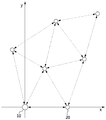
도 2를 참조하면, 2차원 좌표계에 다수의 노드(10, 20)가 위치하고 있으며, 다수의 노드 중 임의의 노드를 위치 추정 장치(10)로 볼 수 있으며, 점선으로 연결된 노드들은 서로 연결된 것으로 볼 수 있다. 즉, 특정 노드와 점선으로 연결된 노드는, 특정 노드와 통신 가능한 범위 내에 위치하고 있는 것으로 볼 수 있다. 여기서, 위치 추정 장치(10)는 2차원 좌표계의 기준점에 위치하고, x축에 하나의 노드(20)가 위치하고 있다. 이때, 위치 추정 장치(10)의 위치는 (0, 0)이거나, (0.001, 0.001)이다.
Referring to FIG. 2, a plurality of
선정부(12)는 네트워크를 구성하는 다수의 노드들로부터 수신한 노드 간의 연결정보를 기반으로 위치 추정의 대상인 표적 노드를 선정할 수 있다. 여기서, 노드 간의 연결정보란, 특정 노드와 통신이 가능한 범위 내에 위치한 노드의 수 및 통신이 가능한 범위 내에 위치한 노드의 특성 정보를 포함한다. 노드의 특성 정보는 자신의 위치를 알고 있는 기준 노드에 해당하는지 자신의 위치를 모르고 있는 노드에 해당하는지를 나타내는 정보를 의미한다.The selecting
선정부(12)는 연결정보를 기반으로 네트워크를 구성하는 노드의 통신 범위 내에 위치하는 기준 노드의 수를 측정하고, 가장 많은 기준 노드가 위치하는 통신 범위를 가지는 노드를 표적 노드로 선정할 수 있다.The selecting
여기서, 선정부(12)는 네트워크를 구성하는 다수의 노드들로부터 주기적 또는 비주기적으로 수신한 연결정보를 기반으로, 특정 노드와 통신이 가능한 범위 내에 위치한 노드의 수 및 통신이 가능한 범위 내에 위치한 노드의 특성 정보를 지속적으로 갱신할 수 있다.
Here, the
추정부(13)는 표적 노드와 기준 노드의 연결관계에 따라 표적 노드의 위치 정보를 추정할 수 있다. 즉, 추정부(13)는 표적 노드의 통신 범위 내에 위치하는 기준 노드의 수에 따라 서로 다른 방법을 적용하여 표적 노드의 위치 정보를 추정할 수 있다.The
표적 노드의 통신 범위 내에 위치하는 기준 노드가 2개인 경우(즉, 표적 노드에 연결된 기준 노드의 수가 2개인 경우), 추정부(13)는, 표적 노드와 하나의 기준 노드 간의 거리와 표적 노드와 다른 하나의 기준 노드 간의 거리의 합과, 하나의 기준 노드와 다른 하나의 기준 노드 간의 거리를 비교한 결과를 기반으로 표적 노드의 위치 정보를 추정할 수 있다.
When there are two reference nodes located within the communication range of the target node (that is, when the number of reference nodes connected to the target node is two), the
도 3은 네트워크를 구성하는 기준 노드의 분포를 나타낸 개념도이다.3 is a conceptual diagram illustrating a distribution of reference nodes constituting a network.
도 3을 참조하여, 표적 노드의 통신 범위 내에 위치하는 기준 노드가 2개인 경우에 표적 노드의 위치 정보를 추정하는 방법에 대해 상세하게 설명한다.Referring to FIG. 3, a method of estimating location information of a target node when two reference nodes are located within a communication range of the target node will be described in detail.
표적 노드의 통신 범위 내에 위치하는 기준 노드(21, 22)가 2개인 경우, 2개의 기준 노드(21, 22)는 표적 노드와 통신을 하여 표적 노드까지 거리를 추정할 수고, 하나의 기준 노드(21)와 다른 하나의 기준 노드(22)는 통신을 통해 서로 간의 거리를 추정할 수 있다. 'P1'은 하나의 기준 노드(21)에서 추정한 표적 노드까지 거리이고, 'P2'는 다른 하나의 기준 노드(22)에서 추정한 표적 노드까지 거리이고, 'L'은 하나의 기준 노드(21)에서 다른 하나의 기준 노드(22)까지의 거리이다.When there are two
일반적으로, 표적 노드의 통신 범위 내에 위치하는 기준 노드(21, 22)가 2개인 경우, 'P1'을 반경으로 하는 가상 원과 'P2'를 반경으로 하는 가상 원은, 적어도 하나의 위치에서 만나게 된다. 이때, 'P1'을 반경으로 하는 가상의 원과 'P2'를 반경으로 하는 가상의 원이 하나의 위치에서 만나는 경우, 그 위치를 해당 표적 노드의 위치 정보로 추정할 수 있다. 'P1'을 반경으로 하는 가상의 원과 'P2'를 반경으로 하는 가상의 원이 두 개의 위치에서 만나는 경우, 두 개의 위치 중 하나의 위치를 해당 표적 노드의 위치 정보로 추정할 수 있다. 여기서, 두 개의 위치 중 하나의 위치를 해당 표적 노드의 위치 정보로 추정하는 경우, 다른 노드들의 연결정보를 기반으로 표적 노드의 위치 정보로 추정할 수 있다.In general, when there are two
한편, 표적 노드의 통신 범위 내에 2개의 기준 노드(20)가 위치하나, 'P1'을 반경으로 하는 가상 원과 'P2'를 반경으로 하는 가상 원이 만나는 위치가 존재하지 않는 경우(L > P1+ P2)가 발생할 수 있다. 이러한 경우는 노드 간의 타이머(클럭) 오차에 의해 발생할 수 있다. 'L'이 'P1+ P2'보다 큰 경우, 추정부(13)는 하나의 기준 노드(21)의 위치 정보와 다른 하나의 기준 노드(22)의 위치 정보 중간값을 표적 노드의 위치 정보로 추정할 수 있다.On the other hand, when two

수학식 2에서, 'PTR'은 표적 노드의 위치 정보이고, 'PNR1'은 하나의 기준 노드(21)의 위치 정보이고, 'PNR2'은 다른 하나의 기준 노드(22)의 위치 정보이다. 즉, 수학식 2를 통해, 'P1'을 반경으로 하는 가상 원과 'P2'를 반경으로 하는 가상 원이 만나는 위치가 존재하지 않는 경우에도 표적 노드의 위치 정보를 추정할 수 있다.
In Equation 2, 'P TR ' is location information of a target node, 'P NR1 ' is location information of one
표적 노드의 통신 범위 내에 위치하는 기준 노드가 3개 이상인 경우(즉, 표적 노드에 연결된 기준 노드의 수가 3개인 연결된 경우), 추정부(13)는, 표적 노드의 통신 범위 내에 위치하는 기준 노드들의 위치 정보를 기반으로 표적 노드의 위치 정보를 추정할 수 있다. 이때, 추정부(13)는 삼각측량법을 사용하여 표적 노드의 위치 정보를 추정할 수 있다. 여기서, 추정된 표적 노드의 위치 정보는 최종 위치 정보가 아니라, 최종 위치 정보의 후보 중의 하나이다.When there are three or more reference nodes located within the communication range of the target node (that is, when the number of reference nodes connected to the target node is three connected), the
표적 노드의 위치 정보를 추정한 후, 추정부(13)는 추정한 표적 노드의 위치 정보와 표적 노드의 통신 범위 내에 위치하는 기준 노드들의 위치 정보 차이를 기반으로 잔차 정보를 생성할 수 있다.After estimating the location information of the target node, the
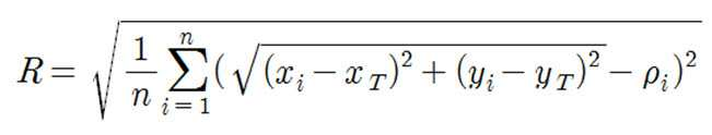
수학식 3에서, 'R'은 잔차 정보이고, 'n'은 표적 노드의 통신 범위 내에 위치한 기준 노드의 수이고, 'xi, yi'는 'i'번째 기준 노드의 위치 정보이고, 'xT, yT'는 추정부(13)가 추정한 표적 노드의 위치 정보이고, 'ρi'는 'i'번째 기준 노드로부터 표적 노드까지 거리이다. 수학식 3을 통해 표적 노드의 위치 정보와 표적 노드의 통신 범위 내에 위치하는 기준 노드들의 위치 정보 차이인 잔차 정보를 생성할 수 있다.In Equation 3, 'R' is the residual information, 'n' is the number of reference nodes located within the communication range of the target node, 'x i , y i ' is the position information of the 'i' reference node, ' x T and y T 'are position information of the target node estimated by the
추정부(13)는 잔차 정보와 미리 정해진 기준값을 비교한 결과에 따라 표적 노드의 위치 정보를 다시 추정하거나, 추정한 표적 노드의 위치 정보를 최종 위치 정보로 확정할 수 있다. 여기서, 기준값은, 추정부(13)에서 추정한 표적 노드의 위치 정보가 정확하게 추정되었는지를 판단하는 기준이 되는 값으로, 잔차 정보가 기준값보다 작거나 같은 경우에 표적 노드의 위치 정보가 정확하게 추정된 것으로 판단할 수 있고, 잔차 정보가 기준값보다 큰 경우에 표적 노드의 위치 정보가 정확하게 추정되지 않은 것으로 판단할 수 있다. 즉, 표적 노드가 이동함에 따라 표적 노드의 통신 범위 내에 위치하는 기준 노드의 개수가 변하게 되는데, 이러한 정보가 갱신되지 않은 경우에 잔차 정보가 기준값보다 커질 수 있다.
The
도 4는 네트워크를 구성하는 기준 노드와 표적 노드의 분포를 나타낸 개념도이다.4 is a conceptual diagram illustrating a distribution of a reference node and a target node constituting a network.
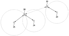
도 4를 참조하여, 잔차 정보가 기준값보다 커지는 경우에 대하여 상세하게 설명한다. 표적 노드(30)는 'A'에서 'B'로 이동을 하며, 표적 노드(30)가'A'에 위치하는 경우에 기준 노드(23)의 통신 범위 내에 표적 노드(30)가 위치하게 되므로, 기준 노드(23)는 표적 노드(30)까지의 거리 정보를 추정하고, 이를 위치 추정 장치(10, 도 1참조)에 제공한다.With reference to FIG. 4, the case where residual information becomes larger than a reference value is demonstrated in detail. The
그 후, 표적 노드(30)가 'B'로 이동하는 경우에 기준 노드(24, 25)의 통신 범위 내에 표적 노드(30)가 위치하게 되므로, 기준 노드(24, 25)는 표적 노드(30)까지의 거리 정보를 추정하고, 이를 위치 추정 장치(10)에 제공한다. 이때, 'A'에 위치하던 표적 노드(30)가 'B'로 이동하였으므로, 기준 노드(23)는 자신의 통신 범위 내에 표적 노드(30)가 위치 하지 않음을 위치 추정 장치(10)에 알려야 하나, 이를 알리지 않거나 알리지 못한 경우에 위치 추정 장치(10)의 입장에서는 표적 노드(30)가 기준 노드(23, 24, 25)의 통신 범위 내에 위치하는 것으로 인식하게 된다.Thereafter, since the
이 경우, 위치 추정 장치(10)는 기준 노드(24, 25)의 위치 정보만을 이용하여 표적 노드의 위치 정보를 추정하여야 하나, 기준 노드(23, 24, 25)의 위치 정보를 이용하여 표적 노드의 위치 정보를 추정하므로, 표적 노드의 위치 정보를 정확하게 추정할 수 없게 된다. 결국, 상술한 경우에서 생성된 잔차 정보는 기준값보다 큰 값을 가질 것이다.
In this case, the
잔차 정보와 기준값을 비교한 결과, 잔차 정보가 기준값보다 작거나 같은 것으로 판단된 경우, 추정부(13)는 기준 노드들의 위치 정보를 기반으로 추정한 표적 노드의 위치 정보를 최종 위치 정보로 확정할 수 있다.As a result of comparing the residual information with the reference value, if the residual information is determined to be less than or equal to the reference value, the
잔차 정보와 기준값을 비교한 결과, 잔차 정보가 기준값보다 큰 것으로 판단된 경우(즉, 상술한 도 4의 경우), 표적 노드의 통신 범위 내에 위치한 기준 노드들 중에서 가장 오래된 위치 정보를 가지는 기준 노드를 제외하고, 나머지 기준 노드들의 위치 정보를 가지고 표적 노드의 위치 정보를 다시 추정할 수 있다.As a result of comparing the residual information with the reference value, if it is determined that the residual information is larger than the reference value (that is, in the case of FIG. 4 described above), the reference node having the oldest location information among the reference nodes located within the communication range of the target node is selected. Except, the location information of the target node may be reestimated based on the location information of the remaining reference nodes.
이때, 가장 오래된 위치 정보를 가지는 기준 노드를 제외한 결과 2개의 기준 노드가 남는 경우, 상술한 방법인 2개의 기준 노드의 위치 정보를 사용하여 표적 노드의 위치 정보를 추정하는 방법을 통해 표적 노드의 위치 정보를 추정할 수 있다. 한편, 가장 오래된 위치 정보를 가지는 기준 노드를 제외한 결과 3개 이상의 기준 노드가 남는 경우, 상술한 방법인 3개 이상의 기준 노드의 위치 정보를 사용하여 표적 노드의 위치 정보를 추정하는 방법을 통해 표적 노드의 위치 정보를 추정할 수 있다.
In this case, when two reference nodes remain as a result of excluding the reference node having the oldest location information, the location of the target node is estimated by using the method of estimating the location information of the target node using the location information of the two reference nodes. Information can be estimated. On the other hand, when three or more reference nodes remain as a result of excluding the reference node having the oldest location information, the target node is estimated by using the method of estimating the location information of the target node using the location information of the three or more reference nodes. The location information of can be estimated.
본 발명에서 설정부(11), 선정부(12) 및 추정부(13)는 서로 독립된 부분으로서 개시되지만, 설정부(11), 선정부(12) 및 추정부(13)는 하나의 단일한 형태, 하나의 물리적인 장치 또는 하나의 모듈로 구현될 수 있다. 이뿐만 아니라, 설정부(11), 선정부(12) 및 추정부(13)는 각각 하나의 물리적인 장치 또는 집단이 아닌 복수의 물리적 장치 또는 집단으로 구현될 수 있다.
In the present invention, the setting
이상 본 발명의 일 실시예에 따른 위치 추정 장치에 대해 상세하게 설명하였다. 이하 본 발명의 일 실시예에 따른 위치 추정 방법에 대해 상세하게 설명한다.
The position estimation device according to the embodiment of the present invention has been described in detail above. Hereinafter, a position estimation method according to an embodiment of the present invention will be described in detail.
도 5는 본 발명의 일 실시예에 따른 위치 추정 방법을 나타낸 동작 흐름도이다.5 is an operation flowchart showing a position estimation method according to an embodiment of the present invention.
도 5를 참조하면, 위치 추정 방법은, 임의의 노드의 위치를 기준으로 좌표계를 설정하는 단계(S100), 네트워크를 구성하는 노드들로부터 노드 간의 연결정보를 수신하는 단계(S200), 연결정보를 기반으로 위치 추정의 대상인 표적 노드를 선정하는 단계(S300) 및 표적 노드와 위치 정보를 알고 있는 기준 노드의 연결관계에 따라 상기 표적 노드의 위치 정보를 추정하는 단계(S400)를 포함한다. 여기서, 위치 추정 방법은 위치 추정 장치(10, 도 1참조)에서 수행될 수 있으며, 위치 추정 장치는 네트워크를 구성하는 노드 중 임의의 노드일 수 있다.Referring to FIG. 5, the location estimation method may include setting a coordinate system based on a location of an arbitrary node (S100), receiving connection information between nodes from nodes constituting a network (S200), and connecting information. Selecting a target node that is the target of the position estimation based on (S300) and estimating the position information of the target node according to the connection relationship between the target node and the reference node that knows the position information (S400). Here, the position estimation method may be performed by the position estimating apparatus 10 (see FIG. 1), and the position estimating apparatus may be any node among the nodes constituting the network.
위치 추정 장치는 자신의 위치 정보를 기준으로 좌표계를 설정할 수 있다(S110). 이때, 위치 추정 장치는 자신의 위치를 기준점으로 하여 2차원 좌표계를 설정하거나, 3차원 좌표계를 설정할 수 있다. 여기서, 2차원 좌표계는 x축, y축으로 구성될 수 있으며, x축과 y축은 서로 수직하도록 위치할 수 있다. 또한, 2차원 좌표계에 위치하는 노드의 위치는 (x, y)로 표현할 수 있다. 3차원 좌표계는 x축, y축, z축으로 구성될 수 있으며, x축, y축, z축은 서로 수직하도록 위치할 수 있다. 또한, 3차원 좌표계에 위치하는 노드의 위치는 (x, y, z)로 표현할 수 있다.The location estimating apparatus may set a coordinate system based on its location information (S110). In this case, the position estimating apparatus may set a two-dimensional coordinate system or set a three-dimensional coordinate system using its position as a reference point. Here, the two-dimensional coordinate system may be composed of the x-axis, y-axis, and the x-axis and the y-axis may be positioned to be perpendicular to each other. In addition, the position of the node located in the two-dimensional coordinate system can be expressed by (x, y). The 3D coordinate system may be composed of x, y, and z axes, and the x, y, and z axes may be positioned to be perpendicular to each other. In addition, the position of the node located in the three-dimensional coordinate system can be represented by (x, y, z).
2차원 좌표계를 설정하는 경우, 위치 추정 장치는 자신의 위치를 (0, 0)으로 하여 2차원 좌표계를 설정할 수 있고, 자신의 위치를 (0.001, 0.001)으로 하여 2차원 좌표계를 설정할 수 있다. 3차원 좌표계를 설정하는 경우, 위치 추정 장치는 자신의 위치를 (0, 0, 0)으로 하여 3차원 좌표계를 설정할 수 있고, 자신의 위치를 (0.001, 0.001, 0.001)으로 하여 3차원 좌표계를 설정할 수 있다. 즉, 좌표계의 설정시에 기준점이 되는 위치 추정 장치의 좌표는 사용자의 설정에 따라 달라진다. 여기서, 좌표계의 단위로 'm'를 사용할 수 있으며, 좌표 (0.001. 0.001)은 x축으로 0.001m, y축으로 0.001m의 위치에 노드가 위치함을 의미할 수 있다.When setting the two-dimensional coordinate system, the position estimating apparatus can set the two-dimensional coordinate system with its own position as (0, 0), and can set the two-dimensional coordinate system with its own position as (0.001, 0.001). When setting the 3D coordinate system, the position estimating apparatus may set the 3D coordinate system by setting its position as (0, 0, 0), and sets the 3D coordinate system with its position as (0.001, 0.001, 0.001). Can be set. That is, the coordinates of the position estimating device which is a reference point when setting the coordinate system vary depending on the user's setting. Here, 'm' may be used as a unit of the coordinate system, and the coordinate (0.001. 0.001) may mean that the node is located at a position of 0.001 m on the x axis and 0.001 m on the y axis.
좌표계를 설정한 후, 위치 추정 장치는 좌표계 중 하나의 축에 네트워크를 구성하는 적어도 하나의 노드가 위치하도록 좌표계를 교정할 수 있다(S120). 예를 들어, 위치 추정 장치가 2차원 좌표계를 설정한 경우, 적어도 하나의 노드가 x축에 위치하도록 좌표계를 교정할 수 있고, 적어도 하나의 노드가 y축에 위치하도록 좌표계를 교정할 수 있다. 이때, 좌표계 중 하나의 축에 위치하는 노드는 위치 추정 장치의 범위 내에 위치하는 노드, 즉 위치 추정 장치와 통신이 가능한 범위 내에 위치한 노드이다.After setting the coordinate system, the position estimating apparatus may calibrate the coordinate system such that at least one node constituting the network is located on one axis of the coordinate system (S120). For example, when the position estimation apparatus sets the two-dimensional coordinate system, the coordinate system may be corrected such that at least one node is located on the x-axis, and the coordinate system may be corrected such that the at least one node is located on the y-axis. In this case, the node located on one axis of the coordinate system is a node located within the range of the position estimating device, that is, a node located within a range capable of communicating with the position estimating device.
좌표계 중 하나의 축에 적어도 하나의 노드가 위치하도록 좌표계를 교정한 후, 위치 추정 장치는 좌표계 중 하나의 축에 위치한 노드의 위치 정보를 추정할 수 있다(S130). 위치 추정 장치는 좌표계 중 하나의 축에 위치한 노드와 통신을 하여 노드까지의 거리를 추정할 수 있고, 추정한 거리를 이용하여 좌표계 중 하나의 축에 위치한 노드의 위치 정보를 추정할 수 있다. 이때, 위치 추정 장치는 도래시간(Time Of Arrival, TOA), 도래시간차(Time Difference Of Arrival, TDOA), 양방향 거리측정(Two-Way Ranging) 방법 등을 사용하여, 위치 추정 장치로부터 좌표계 중 하나의 축에 위치한 노드까지의 거리를 추정할 수 있다. 이때, 위치 추정 장치는 상술한 수학식 1을 통해 노드의 위치 정보를 추정할 수 있다. 여기서, 'PBT'는 좌표계 중 하나의 축에 위치한 노드의 위치 정보이고, 'ρM- BT'는 위치 추정 장치로부터 좌표계 중 하나의 축에 위치한 노드까지의 거리이고, '0.001'은 위치 추정 장치의 y축 좌표이다.After calibrating the coordinate system such that at least one node is located on one axis of the coordinate system, the position estimating apparatus may estimate position information of a node located on one axis of the coordinate system (S130). The position estimating apparatus may estimate a distance to a node by communicating with a node located on one axis of the coordinate system, and estimate position information of a node located on one axis of the coordinate system by using the estimated distance. In this case, the position estimating apparatus uses a time of arrival (TOA), a time difference of arrival (TDOA), a two-way ranging method, and the like. The distance to the node located on the axis can be estimated. In this case, the position estimating apparatus may estimate the position information of the node through the above equation (1). Here, 'P BT ' is position information of a node located in one axis of the coordinate system, 'ρ M- BT ' is a distance from the position estimation device to a node located in one axis of the coordinate system, and '0.001' is a position estimate The y-axis coordinate of the device.
위치 추정 장치는 네트워크를 구성하는 노드 간의 연결정보를 노드들로부터 수신할 수 있다(S200). 위치 추정 장치는, 단계 S100을 수행한 후 단계 S200을 수행할 수 있고, 단계 S100을 수행하기 전에 단계 S200을 수행할 수도 있다. 여기서, 노드 간의 연결정보란, 특정 노드와 통신이 가능한 범위 내에 위치한 노드의 수 및 통신이 가능한 범위 내에 위치한 노드의 특성 정보를 포함한다. 노드의 특성 정보는 자신의 위치를 알고 있는 기준 노드에 해당하는지 자신의 위치를 모르고 있는 노드에 해당하는지를 나타내는 정보이다. 위치 추정 장치는 주기적 또는 비주기적으로 노드 간의 연결정보를 수신하여, 특정 노드와 통신이 가능한 범위 내에 위치한 노드의 수 및 통신이 가능한 범위 내에 위치한 노드의 특성 정보를 갱신할 수 있다.The location estimating apparatus may receive connection information between nodes constituting the network from the nodes (S200). The location estimation apparatus may perform step S200 after performing step S100, and may perform step S200 before performing step S100. Here, the connection information between the nodes includes the number of nodes located within a range capable of communicating with a specific node and characteristic information of nodes located within a range capable of communicating. The characteristic information of the node is information indicating whether it corresponds to a reference node that knows its location or a node that does not know its location. The location estimating apparatus may periodically or aperiodically receive connection information between nodes, and may update the number of nodes located within a range capable of communicating with a specific node and characteristic information of nodes located within a range capable of communicating.
노드 간의 연결정보를 수신한 후, 위치 추정 장치는 노드 간의 연결정보를 기반으로 위치 추정의 대상인 표적 노드를 선정할 수 있다(S300). 위치 추정 장치는 연결정보를 기반으로 네트워크를 구성하는 노드의 통신 범위 내에 위치하는 기준 노드의 수를 측정(즉, 노드에 연결(접속)된 기준 노드의 수를 측정)하고, 가장 많은 기준 노드가 위치하는 통신 범위를 가지는 노드를 표적 노드로 선정할 수 있다.After receiving the connection information between the nodes, the position estimating apparatus may select a target node that is a target of position estimation based on the connection information between the nodes (S300). The location estimating apparatus measures the number of reference nodes located within the communication range of the nodes constituting the network based on the connection information (that is, the number of reference nodes connected (connected) to the node), and the most reference nodes A node having a communication range located may be selected as a target node.
연결정보를 기반으로 표적 노드를 선정한 후, 위치 추정 장치는 표적 노드의 위치 정보를 추정할 수 있다(S400).
After selecting the target node based on the connection information, the location estimating apparatus may estimate the location information of the target node (S400).
도 6은 도 5에 도시된 표적 노드의 위치 정보 추정 단계를 상세히 나타낸 동작 흐름도이다.FIG. 6 is a flowchart illustrating an operation of estimating location information of a target node illustrated in FIG. 5 in detail.
도 6을 참조하면, 위치 추정 장치는 표적 노드의 통신 범위 내에 위치하는 기준 노드의 수에 따라 표적 노드의 위치 정보를 추정할 수 있다.Referring to FIG. 6, the location estimating apparatus may estimate location information of the target node according to the number of reference nodes located within the communication range of the target node.
표적 노드의 통신 범위 내에 2개의 기준 노드가 위치(즉, 표적 노드에 연결된 기준 노드의 수가 2개인 경우)하는 것으로 판단되면, 위치 추정 장치는 'L'(하나의 기준 노드(21)와 다른 하나의 기준 노드(22) 간의 거리, 도 3 참조)와 'P1 + P2'('P1'은 하나의 기준 노드(21)에서 추정한 표적 노드까지 거리, 'P2'는 다른 하나의 기준 노드(22)에서 추정한 표적 노드까지 거리, 도 3참조)의 크기를 비교한 결과에 따라 표적 노드의 위치 정보를 추정할 수 있다.If it is determined that two reference nodes are located within the communication range of the target node (that is, when there are two reference nodes connected to the target node), the position estimating apparatus is 'L' (one
예를 들어, 'L = P1+ P2' 인 경우('P1'을 반경으로 하는 가상 원과 'P2'를 반경으로 하는 가상 원이 하나의 위치에서 만나는 경우), 위치 추정 장치는 'P1'을 반경으로 하는 가상 원과 'P2'를 반경으로 하는 가상 원이 만나는 위치를 표적 노드의 위치 정보로 추정할 수 있다(S410).For example, 'L = P 1 + P 2 ' (When a virtual circle with radius' P 1 'and a virtual circle with radius' P 2 ' meet at one position), the position estimating device is a virtual circle with radius' P 1 'and' P The position where the virtual circle having a radius of 2 'meets may be estimated as position information of the target node (S410).
'L < P1+ P2'인 경우('P1'을 반경으로 하는 가상 원과 'P2'를 반경으로 하는 가상 원이 두 개의 위치에서 만나는 경우), 위치 추정 장치는 'P1'을 반경으로 하는 가상 원과 'P2'를 반경으로 하는 가상 원이 만나는 위치 중 하나의 위치를 표적 노드의 위치 정보로 추정할 수 있다(S410). 이때, 두 개의 위치 중 하나의 위치를 해당 표적 노드의 위치 정보로 추정하는 경우, 위치 추정 장치는 다른 노드들의 연결정보를 기반으로 표적 노드의 위치 정보를 추정할 수 있다.If 'L <P 1 + P 2 ' (the virtual circle with radius 'P 1 ' and the virtual circle with radius 'P 2 ' meet at two positions), the position estimator is 'P 1 ' The position of one of the positions where the virtual circle having a radius and the virtual circle having a radius of 'P 2 ' may be estimated as location information of the target node (S410). In this case, when estimating the position of one of the two positions as the position information of the target node, the position estimating apparatus may estimate the position information of the target node based on the connection information of the other nodes.
'L > P1+ P2'인 경우('P1'을 반경으로 하는 가상 원과 'P2'를 반경으로 하는 가상 원이 만나지 않는 경우), 위치 추정 장치는 하나의 기준 노드의 위치 정보와 다른 하나의 기준 노드의 위치 정보 중간값을 표적 노드의 위치 정보로 추정할 수 있다(S420). 이때, 위치 추정 장치는 상술한 수학식 2를 통해 표적 노드의 위치 정보를 추정할 수 있다. 여기서, 'PTR'은 표적 노드의 위치 정보이고, 'PNR1'은 하나의 기준 노드의 위치 정보이고, 'PNR2'은 다른 하나의 기준 노드의 위치 정보이다.In the case of 'L> P 1 + P 2 ' (when a virtual circle having a radius of 'P 1 ' does not meet a virtual circle having a radius of 'P 2 '), the position estimating device determines the position information of one reference node. In operation S420, a median value of location information of another reference node may be estimated as location information of a target node. In this case, the position estimating apparatus may estimate the position information of the target node through the above equation (2). Here, 'P TR ' is location information of the target node, 'P NR1 ' is location information of one reference node, and 'P NR2 ' is location information of another reference node.
표적 노드의 통신 범위 내에 3개 이상의 기준 노드가 위치(표적 노드에 연결된 기준 노드의 개수가 3인 경우)하는 것으로 판단되면, 위치 추정 장치는 표적 노드의 통신 범위 내에 위치하는 기준 노드들의 위치 정보를 기반으로 표적 노드의 위치 정보를 추정할 수 있다(S430). 이때, 위치 추정 장치는 삼각측량법을 사용하여 표적 노드의 위치 정보를 추정할 수 있다. 여기서, 단계 S430을 통해 추정된 표적 노드의 위치 정보는 최종 위치 정보가 아니라, 최종 위치 정보의 후보 중의 하나이다.If it is determined that three or more reference nodes are located within the communication range of the target node (when the number of reference nodes connected to the target node is three), the position estimating apparatus obtains the position information of the reference nodes located within the communication range of the target node. Based on the location information of the target node can be estimated (S430). In this case, the location estimating apparatus may estimate location information of the target node using triangulation. Here, the position information of the target node estimated through step S430 is one of the candidates of the final position information, not the final position information.
표적 노드의 위치 정보를 추정한 후, 위치 추정 장치는 추정한 표적 노드의 위치 정보와 표적 노드의 통신 범위 내에 위치하는 기준 노드들의 위치 정보 차이를 기반으로 잔차 정보를 생성할 수 있다(S440). 이때, 위치 추정 장치는 상술한 수학식 3을 통해 잔차 정보를 생성할 수 있다. 여기서, 'R'은 잔차 정보이고, 'n'은 표적 노드의 통신 범위 내에 위치한 기준 노드의 수이고, 'xi, yi'는 'i'번째 기준 노드의 위치 정보이고, 'xT, yT'는 위치 추정 장치가 추정한 표적 노드의 위치 정보이고, 'ρi'는 'i'번째 기준 노드로부터 표적 노드까지 거리이다.After estimating the location information of the target node, the location estimating apparatus may generate the residual information based on the difference between the estimated location information of the target node and the location information of the reference nodes located within the communication range of the target node (S440). In this case, the position estimating apparatus may generate residual information through the above-described equation (3). Here, 'R' is the residual information, 'n' is the number of reference nodes located within the communication range of the target node, 'x i , y i ' is the location information of the 'i' reference node, 'x T , y T 'is position information of the target node estimated by the position estimating apparatus, and' ρ i 'is a distance from the' i 'th reference node to the target node.
잔차 정보를 생성한 후, 위치 추정 장치는 잔차 정보와 미리 정해진 기준값을 비교한 결과에 따라 표적 노드의 위치를 다시 추정하거나, 추정한 표적 노드의 위치 정보를 최종 위치 정보로 확정할 수 있다. 여기서, 기준값은, 위치 추정 장치에서 추정한 표적 노드의 위치 정보가 정확하게 추정되었는지를 판단하는 기준이 되는 값으로, 잔차 정보가 기준값보다 작거나 같은 경우에 표적 노드의 위치 정보가 정확하게 추정된 것으로 판단할 수 있고, 잔차 정보가 기준값보다 큰 경우에 표적 노드의 위치 정보가 정확하게 추정되지 않은 것으로 판단할 수 있다. 즉, 표적 노드가 이동함에 따라 표적 노드의 통신 범위 내에 위치하는 기준 노드의 개수가 변하게 되는데, 이러한 정보가 갱신되지 않은 경우에 잔차 정보가 기준값보다 커질 수 있다(상술한 도 4의 경우).After generating the residual information, the position estimating apparatus may estimate the position of the target node again based on a result of comparing the residual information with a predetermined reference value, or may determine the estimated position information of the target node as final position information. Here, the reference value is a value for determining whether the position information of the target node estimated by the position estimating apparatus is accurately estimated, and it is determined that the position information of the target node is correctly estimated when the residual information is less than or equal to the reference value. If the residual information is larger than the reference value, it may be determined that the location information of the target node is not accurately estimated. That is, as the target node moves, the number of reference nodes positioned within the communication range of the target node changes. When such information is not updated, the residual information may be larger than the reference value (in the case of FIG. 4 described above).
잔차 정보와 기준값을 비교한 결과, 잔차 정보가 기준값보다 작거나 같은 것으로 판단된 경우, 위치 추정 장치는 단계 S430에서 추정한 표적 노드의 위치 정보를 최종 위치 정보로 확정할 수 있다(단계 S450).As a result of comparing the residual information with the reference value, when it is determined that the residual information is smaller than or equal to the reference value, the position estimating apparatus may determine the position information of the target node estimated in step S430 as final position information (step S450).
잔차 정보와 기준값을 비교한 결과, 잔차 정보가 기준값보다 큰 것으로 판단된 경우(즉, 상술한 도 4의 경우), 위치 추정 장치는 표적 노드의 통신 범위 내에 위치한 기준 노드들 중에서 가장 오래된 위치 정보를 가지는 기준 노드를 제외하고(S460), 나머지 기준 노드들의 위치 정보를 가지고 표적 노드의 위치 정보를 다시 추정할 수 있다.As a result of comparing the residual information with the reference value, if it is determined that the residual information is larger than the reference value (that is, in the case of FIG. 4 described above), the position estimating apparatus may determine the oldest position information among the reference nodes located within the communication range of the target node. With the exception of the reference node (S460), the location information of the target node may be reestimated based on the location information of the remaining reference nodes.
이때, 가장 오래된 위치 정보를 가지는 기준 노드를 제외한 결과 2개의 기준 노드가 남는 경우, 상술한 방법인 2개의 기준 노드의 위치 정보를 사용하여 표적 노드의 위치 정보를 추정하는 방법(S410, S420)을 통해 표적 노드의 위치 정보를 추정할 수 있다. 한편, 가장 오래된 위치 정보를 가지는 기준 노드를 제외한 결과 3개 이상의 기준 노드가 남는 경우, 상술한 방법인 3개 이상의 기준 노드의 위치 정보를 사용하여 표적 노드의 위치 정보를 추정하는 방법(S430, S440, S450, S460)을 통해 표적 노드의 위치 정보를 추정할 수 있다.
In this case, when two reference nodes remain as a result of excluding the reference node having the oldest location information, the method of estimating the location information of the target node using the location information of the two reference nodes as described above (S410 and S420) Through the location information of the target node can be estimated. On the other hand, when three or more reference nodes remain as a result of excluding the reference node having the oldest location information, a method of estimating the location information of the target node using the location information of the three or more reference nodes as described above (S430 and S440). The location information of the target node may be estimated through S450 and S460.
이상에서와 같이 본 발명에 따른 위치 추정 장치 및 방법은 상기한 바와 같이 설명된 실시예들의 구성과 방법이 한정되게 적용될 수 있는 것이 아니라, 상기 실시예들은 다양한 변형이 이루어질 수 있도록 각 실시예들의 전부 또는 일부가 선택적으로 조합되어 구성될 수도 있다.As described above, the apparatus and method for estimating position according to the present invention may not be limitedly applied to the configuration and method of the embodiments described as described above, but the embodiments are all of the embodiments so that various modifications can be made. Or some may be selectively combined.
10: 위치 추정 장치
11: 설정부
12: 선정부
13: 추정부
20: 기준 노드
30: 표적 노드10: position estimation device
11: setting part
12: selection
13: estimator
20: reference node
30: target node
Claims (12)
네트워크를 구성하는 다수의 노드로부터 수신한 노드 간의 연결정보를 기반으로, 위치 추정의 대상인 표적 노드를 선정하는 선정부; 및
상기 표적 노드와 위치 정보를 알고 있는 기준 노드의 연결관계에 따라 상기 표적 노드의 위치 정보를 추정하는 추정부를 포함하는 위치 추정 장치.A setting unit that sets a coordinate system based on the location information;
A selection unit for selecting a target node, which is a target of position estimation, based on connection information between nodes received from a plurality of nodes constituting a network; And
And an estimator for estimating the position information of the target node according to a connection relationship between the target node and a reference node that knows the position information.
위치 정보를 기준점으로 하여 좌표계를 설정하고, 좌표계 중 하나의 축에 네트워크를 구성하는 적어도 하나의 노드가 위치하도록 좌표계를 교정하고, 기준점과 상기 적어도 하나의 노드 간의 거리 추정을 통해 상기 적어도 하나의 노드의 위치 정보를 추정하는 것을 특징으로 하는 위치 추정 장치.The method according to claim 1, wherein the setting unit,
Set a coordinate system using the position information as a reference point, correct the coordinate system so that at least one node constituting the network is located on one axis of the coordinate system, and estimate the distance between the reference point and the at least one node by using the at least one node. And estimating position information of the apparatus.
네트워크를 구성하는 노드들 중 가장 많은 기준 노드와 연결된 노드를 상기 표적 노드로 선정하는 것을 특징으로 하는 위치 추정 장치.The method according to claim 1, wherein the selection unit,
And a node connected to the most reference node among the nodes constituting the network as the target node.
상기 표적 노드에 연결된 기준 노드의 수가 2개인 경우,
상기 표적 노드와 하나의 기준 노드 간의 거리와 상기 표적 노드와 다른 하나의 기준 노드 간의 거리의 합이, 하나의 기준 노드와 다른 하나의 기준 노드 간의 거리보다 작은 것으로 판단되면,
하나의 기준 노드 위치 정보와 다른 하나의 기준 노드 위치 정보의 중간값을 상기 표적 노드의 위치 정보로 추정하는 것을 특징으로 하는 위치 추정 장치.The method according to claim 1, wherein the estimating unit,
When the number of reference nodes connected to the target node is two,
If it is determined that the sum of the distance between the target node and one reference node and the distance between the target node and the other reference node is smaller than the distance between one reference node and the other reference node,
And estimating a median value of one reference node position information and another reference node position information as position information of the target node.
상기 표적 노드에 연결된 기준 노드의 수가 3개 이상인 경우,
상기 표적 노드에 연결된 기준 노드들의 위치 정보를 기반으로 상기 표적 노드의 위치 정보를 추정하고, 추정한 표적 노드의 위치 정보와 상기 표적 노드에 연결된 기준 노드들의 위치 정보 차이를 기반으로 잔차 정보를 생성하고, 상기 잔차 정보와 미리 정해진 기준값을 비교한 결과에 따라 상기 표적 노드의 위치를 다시 추정하거나, 추정한 표적 노드의 위치 정보를 최종 위치 정보로 확정하는 것을 특징으로 하는 위치 추정 장치.The method according to claim 1, wherein the estimating unit,
When the number of reference nodes connected to the target node is three or more,
Estimate location information of the target node based on location information of the reference nodes connected to the target node, generate residual information based on a difference between the estimated location information of the target node and location information of the reference nodes connected to the target node; And re-estimating the location of the target node according to a result of comparing the residual information with a predetermined reference value, or determining the estimated location information of the target node as final location information.
상기 잔차 정보가 미리 정해진 기준값 보다 큰 경우, 상기 표적 노드에 연결된 기준 노드들의 위치 정보 중 가장 오래된 위치 정보를 제외한 나머지 위치 정보를 기반으로 상기 표적 노드의 위치 정보를 다시 추정하고,
상기 잔차 정보가 미리 정해진 기준값 보다 작거나 같은 경우, 추정한 표적 노드의 위치 정보를 최종 위치 정보로 확정하는 것을 특징으로 하는 위치 추정 장치.The method according to claim 5, wherein the estimating unit,
When the residual information is larger than a predetermined reference value, the location information of the target node is estimated again based on the remaining location information except the oldest location information among the location information of the reference nodes connected to the target node,
And when the residual information is less than or equal to a predetermined reference value, determining the estimated position information of the target node as final position information.
상기 임의의 노드의 위치를 기준으로 좌표계를 설정하는 단계;
네트워크를 구성하는 노드들로부터 노드 간의 연결정보를 수신하는 단계;
상기 연결정보를 기반으로 위치 추정의 대상인 표적 노드를 선정하는 단계; 및
상기 표적 노드와 위치 정보를 알고 있는 기준 노드의 연결관계에 따라 상기 표적 노드의 위치 정보를 추정하는 단계를 포함하는 위치 추정 방법.In the location estimation method performed in any of a plurality of nodes constituting the network,
Setting a coordinate system based on the position of the arbitrary node;
Receiving connection information between nodes from nodes constituting the network;
Selecting a target node that is a target of position estimation based on the connection information; And
And estimating location information of the target node according to a connection relationship between the target node and a reference node that knows the location information.
상기 임의의 노드의 위치를 기준점으로 하여 좌표계를 설정하는 단계;
좌표계 중 하나의 축에 네트워크를 구성하는 적어도 하나의 노드가 위치하도록 좌표계를 교정하는 단계; 및
상기 기준점과 상기 적어도 하나의 노드 간의 거리 추정을 통해 상기 적어도 하나의 노드 위치 정보를 추정하는 단계를 포함하는 위치 추정 방법.The method of claim 7, wherein the setting of the coordinate system based on the position of the arbitrary node,
Setting a coordinate system based on a position of the arbitrary node;
Calibrating the coordinate system such that at least one node constituting the network is located on one axis of the coordinate system; And
Estimating the at least one node position information by estimating a distance between the reference point and the at least one node.
네트워크를 구성하는 노드들 중 가장 많은 기준 노드와 연결된 노드를 상기 표적 노드로 선정하는 것을 특징으로 하는 위치 추정 방법.The method of claim 7, wherein the step of selecting a target node that is the target of position estimation based on the connection information,
And selecting a node connected to the largest reference node among the nodes constituting the network as the target node.
상기 표적 노드에 연결된 기준 노드의 수가 2개인 경우,
상기 표적 노드와 하나의 기준 노드 간의 거리와 상기 표적 노드와 다른 하나의 기준 노드 간의 거리의 합이, 하나의 기준 노드와 다른 하나의 기준 노드 간의 거리보다 작은 것으로 판단되면,
하나의 기준 노드 위치 정보와 다른 하나의 기준 노드 위치 정보의 중간값을 상기 표적 노드의 위치 정보로 추정하는 것을 특징으로 하는 위치 추정 방법.The method of claim 7, wherein estimating the location information of the target node according to the connection relationship between the target node and the reference node that knows the location information,
When the number of reference nodes connected to the target node is two,
If it is determined that the sum of the distance between the target node and one reference node and the distance between the target node and the other reference node is smaller than the distance between one reference node and the other reference node,
And estimating a median value of one reference node position information and another reference node position information as position information of the target node.
상기 표적 노드에 연결된 기준 노드의 수가 3개 이상인 경우,
상기 표적 노드에 연결된 기준 노드들의 위치 정보를 기반으로 상기 표적 노드의 위치 정보를 추정하는 단계;
추정한 표적 노드의 위치 정보와 상기 표적 노드에 연결된 기준 노드들의 위치 정보 차이를 기반으로 잔차 정보를 생성하는 단계; 및
상기 잔차 정보와 미리 정해진 기준값을 비교한 결과에 따라 상기 표적 노드의 위치 정보를 다시 추정하거나, 추정한 표적 노드의 위치 정보를 최종 위치 정보로 확정하는 단계를 포함하는 위치 추정 방법.The method of claim 7, wherein estimating the location information of the target node according to the connection relationship between the target node and the reference node that knows the location information,
When the number of reference nodes connected to the target node is three or more,
Estimating location information of the target node based on location information of reference nodes connected to the target node;
Generating residual information based on a difference between the estimated location information of the target node and the location information of reference nodes connected to the target node; And
And re-estimating the position information of the target node according to a result of comparing the residual information with a predetermined reference value, or determining the estimated position information of the target node as final position information.
상기 잔차 정보가 미리 정해진 기준값 보다 큰 경우, 상기 표적 노드에 연결된 기준 노드들의 위치 정보 중 가장 오래된 위치 정보를 제외한 나머지 위치 정보를 기반으로 상기 표적 노드의 위치 정보를 다시 추정하는 단계; 및
상기 잔차 정보가 미리 정해진 기준값 보다 작거나 같은 경우, 추정한 표적 노드의 위치 정보를 최종 위치 정보로 확정하는 단계를 포함하는 위치 추정 방법.The method of claim 11, wherein re-estimating the location information of the target node or determining the estimated location information of the target node as final location information according to a result of comparing the residual information with a predetermined reference value.
If the residual information is greater than a predetermined reference value, re-estimating the location information of the target node based on the remaining location information except the oldest location information among the location information of the reference nodes connected to the target node; And
If the residual information is less than or equal to a predetermined reference value, determining position information of the estimated target node as final position information.
Priority Applications (2)
| Application Number | Priority Date | Filing Date | Title |
|---|---|---|---|
| KR1020120060312A KR20130136708A (en) | 2012-06-05 | 2012-06-05 | Apparatus and method for estimating location |
| US13/775,652 US20130324150A1 (en) | 2012-06-05 | 2013-02-25 | Location estimation apparatus and method |
Applications Claiming Priority (1)
| Application Number | Priority Date | Filing Date | Title |
|---|---|---|---|
| KR1020120060312A KR20130136708A (en) | 2012-06-05 | 2012-06-05 | Apparatus and method for estimating location |
Publications (1)
| Publication Number | Publication Date |
|---|---|
| KR20130136708A true KR20130136708A (en) | 2013-12-13 |
Family
ID=49670858
Family Applications (1)
| Application Number | Title | Priority Date | Filing Date |
|---|---|---|---|
| KR1020120060312A KR20130136708A (en) | 2012-06-05 | 2012-06-05 | Apparatus and method for estimating location |
Country Status (2)
| Country | Link |
|---|---|
| US (1) | US20130324150A1 (en) |
| KR (1) | KR20130136708A (en) |
Families Citing this family (9)
| Publication number | Priority date | Publication date | Assignee | Title |
|---|---|---|---|---|
| US9407317B2 (en) * | 2013-04-03 | 2016-08-02 | Umm Al-Qura University | Differential ultra-wideband indoor positioning method |
| BE1023168B1 (en) * | 2014-03-25 | 2016-12-08 | Bordersystem Sprl | SYSTEM OF PROTECTION OF PEOPLE ON SITE BY PRECISE LOCATION. |
| CN104796910B (en) * | 2015-03-12 | 2018-05-29 | 国家电网公司 | A kind of anchor node energy-saving type positioning network-building method based on Nash Equilibrium |
| US20170265041A1 (en) * | 2016-03-09 | 2017-09-14 | Honeywell International Inc. | Systems, methods, and devices for indoor location |
| US10382894B2 (en) | 2017-07-28 | 2019-08-13 | Electronics And Telecommunications Research Institute | Method of measuring inter-device relative coordinates and device using the same |
| CN107948945B (en) * | 2017-11-08 | 2020-04-28 | 顺丰科技有限公司 | Communication control system and control method for indoor positioning |
| US10534068B2 (en) * | 2018-12-27 | 2020-01-14 | Intel Corporation | Localization system, vehicle control system, and methods thereof |
| CN110286358A (en) * | 2019-06-28 | 2019-09-27 | 努比亚技术有限公司 | A kind of indoor orientation method, equipment and computer readable storage medium |
| CN116996996B (en) * | 2023-09-27 | 2023-12-12 | 中国电建集团贵阳勘测设计研究院有限公司 | Intelligent construction site operation and maintenance management and control positioning method and system |
Family Cites Families (4)
| Publication number | Priority date | Publication date | Assignee | Title |
|---|---|---|---|---|
| US8565788B2 (en) * | 2005-02-03 | 2013-10-22 | Mexens Intellectual Property Holding Llc | Method and system for obtaining location of a mobile device |
| US8634860B2 (en) * | 2010-01-15 | 2014-01-21 | Apple Inc. | Location determination using cached location area codes |
| US8494554B2 (en) * | 2011-06-03 | 2013-07-23 | Apple Inc. | Mobile device location estimation |
| US20130072220A1 (en) * | 2011-09-19 | 2013-03-21 | Qualcomm Atheros, Inc. | Hybrid tdoa and toa based positioning system |
-
2012
- 2012-06-05 KR KR1020120060312A patent/KR20130136708A/en not_active Application Discontinuation
-
2013
- 2013-02-25 US US13/775,652 patent/US20130324150A1/en not_active Abandoned
Also Published As
| Publication number | Publication date |
|---|---|
| US20130324150A1 (en) | 2013-12-05 |
Similar Documents
| Publication | Publication Date | Title |
|---|---|---|
| KR20130136708A (en) | Apparatus and method for estimating location | |
| CN109218282B (en) | Pulse shaping interoperability protocol for ultra-wideband systems | |
| EP3186654B1 (en) | Method and apparatus for real-time, mobile-based positioning according to sensor and radio frequency measurements | |
| US10382894B2 (en) | Method of measuring inter-device relative coordinates and device using the same | |
| Hepp et al. | Omni-directional person tracking on a flying robot using occlusion-robust ultra-wideband signals | |
| US20160183057A1 (en) | Method and system for hybrid location detection | |
| KR101814698B1 (en) | Method for simultaneously setting coordinates of anchor and tag using wireless transmission / reception and communication system thereof | |
| KR101608976B1 (en) | System and Method of Collaborative Localization Using Short Range Wireless Communication Network Without Location Infrastructure | |
| Zwirello et al. | Sensor data fusion in UWB-supported inertial navigation systems for indoor navigation | |
| US20230063193A1 (en) | Location system with ultra-wideband (uwb) infrastructure and discovery infrastructure | |
| Chen et al. | Smartphone-based indoor positioning technologies | |
| Kim et al. | NLOS identification based UWB and PDR hybrid positioning system | |
| Syberfeldt et al. | Localizing operators in the smart factory: A review of existing techniques and systems | |
| Pelka et al. | S-TDoA—Sequential time difference of arrival—A scalable and synchronization free approach forl positioning | |
| Tiemann et al. | Ultra-wideband aided precision parking for wireless power transfer to electric vehicles in real life scenarios | |
| CN112272782A (en) | Temporary location of mobile devices using nearby ultrasound signals | |
| US20170126273A1 (en) | Location measuring method and system for acceptable a plurality of uwb tags | |
| Oliveira et al. | Fusing time-of-flight and received signal strength for adaptive radio-frequency ranging | |
| Korogodin et al. | Comparison of local ultra-wideband radio navigation systems architectures | |
| US20120165040A1 (en) | Method for locating wireless nodes using difference triangulation | |
| CN105580461A (en) | Method and positioning device for localization of a mobile communication device | |
| KR20120030756A (en) | Positioning system and method based on single visible light communication apparatus comprising multiple light sources | |
| KR101268574B1 (en) | Apparatus and method for estimating tag location | |
| US7965237B2 (en) | Mobile system and method for position estimation | |
| KR102112906B1 (en) | Real-time location method and system with improved accuracy |
Legal Events
| Date | Code | Title | Description |
|---|---|---|---|
| WITN | Application deemed withdrawn, e.g. because no request for examination was filed or no examination fee was paid |