KR20130131567A - System capable of controlling security light - Google Patents
System capable of controlling security light Download PDFInfo
- Publication number
- KR20130131567A KR20130131567A KR1020120055204A KR20120055204A KR20130131567A KR 20130131567 A KR20130131567 A KR 20130131567A KR 1020120055204 A KR1020120055204 A KR 1020120055204A KR 20120055204 A KR20120055204 A KR 20120055204A KR 20130131567 A KR20130131567 A KR 20130131567A
- Authority
- KR
- South Korea
- Prior art keywords
- lighting lamp
- security
- lamp
- security light
- lighting
- Prior art date
Links
Images

Classifications
-
- H—ELECTRICITY
- H05—ELECTRIC TECHNIQUES NOT OTHERWISE PROVIDED FOR
- H05B—ELECTRIC HEATING; ELECTRIC LIGHT SOURCES NOT OTHERWISE PROVIDED FOR; CIRCUIT ARRANGEMENTS FOR ELECTRIC LIGHT SOURCES, IN GENERAL
- H05B41/00—Circuit arrangements or apparatus for igniting or operating discharge lamps
-
- Y—GENERAL TAGGING OF NEW TECHNOLOGICAL DEVELOPMENTS; GENERAL TAGGING OF CROSS-SECTIONAL TECHNOLOGIES SPANNING OVER SEVERAL SECTIONS OF THE IPC; TECHNICAL SUBJECTS COVERED BY FORMER USPC CROSS-REFERENCE ART COLLECTIONS [XRACs] AND DIGESTS
- Y02—TECHNOLOGIES OR APPLICATIONS FOR MITIGATION OR ADAPTATION AGAINST CLIMATE CHANGE
- Y02B—CLIMATE CHANGE MITIGATION TECHNOLOGIES RELATED TO BUILDINGS, e.g. HOUSING, HOUSE APPLIANCES OR RELATED END-USER APPLICATIONS
- Y02B20/00—Energy efficient lighting technologies, e.g. halogen lamps or gas discharge lamps
- Y02B20/40—Control techniques providing energy savings, e.g. smart controller or presence detection
Abstract
Description
본 발명은 보안등에 관한 것으로서, 보다 상세하게는, 보안등 제어 시스템에 관한 것이다.The present invention relates to security and the like, and more particularly, to a control system, such as security.
일반적으로, 공장이나 건물 등의 주요 시설물이나, 인적이 드문 골목길 등 범죄 발생이 빈번한 사각지대에는 야간에 주변을 밝히기 위한 등(Lamp)이 설치되어 있으며, 이는 포괄적인 의미에서 보안등(security light 또는 guard Lamp)으로 명명될 수 있다.Generally, lamps are installed to illuminate the surroundings at night in major blind spots such as factories or buildings, or in rare alleys, such as security lights or security lights. guard lamp).
이러한 보안등은 계절 또는 날씨 등의 주변 조건에 따라 적정한 시간에 점멸되어야 하며 이러한 점멸시간의 조절 및 보안등의 관리를 간편하게 하기 위한 다양한 방법들이 제시되고 있다.Such security lights should be blinked at an appropriate time according to the surrounding conditions such as seasons or weather, and various methods for simplifying control of such blinking time and security are proposed.
보안등의 점등 및 소등을 위해서는 다음과 같은 여러 가지 방식을 사용하며, 조명을 요구하는 장소의 용도에 맞게 선택하여 사용하게 된다. 보안등의 점등 및 소등 제어방식으로는, 보안등에 설치된 안테나를 통해 관제센터로부터 점등 또는 소등을 위한 무선신호를 수신하여 원격으로 점등 또는 소등을 수행하는 단방향 무선원격 제어방식과, 보안등 내부에 빛을 감지하는 센서를 설치하여 어두워지면 자동으로 점등되고 밝아지면 자동으로 소등되는 썬 스위치(sun switch) 방식과, 보안등의 점등 또는 소등을 위한 차단기를 직접 조작하여 점등 또는 소등하는 직접작동 방식과, 일출시간 및 일몰시간을 사전에 입력해 놓고 자동 타이머의 시간을 통해 자동으로 점등 또는 소등시키는 타이머 방식 등이 있을 수 있다.To turn on and off the security light, various methods are used as follows, and it is selected and used according to the purpose of the place requiring lighting. The lighting and lighting control method of the security light includes a one-way radio remote control method that receives a wireless signal for lighting or turning off from a control center through an antenna installed in the security light and performs lighting or turning off remotely. Sun switch type that automatically turns on when it is dark and turns off automatically when it is dark, and direct operation method that turns on or off by directly operating the breaker for turning on or off the security light, and sunrise time And a timer type for automatically setting the sunset time and turning on or off automatically through the time of the automatic timer.
그러나 상술한 바와 같은 종래의 보안등은, 단순히 관제센터에서 일괄적으로 점등 및 소등을 제어하거나, 타이머나 센서의 동작에 따른 점등 및 소등이 이루어질 뿐, 보안등을 관리하는 관제센터에서 각 보안등의 작동상태를 정확하게 파악하는 것이 불가능하기 때문에 보안등에 이상이 발생되는 경우 야간순찰이나 주민들의 신고에 의존하여 유지관리에 어려움이 따랐고, 각 보안등의 개별적인 점등 및 소등을 제어할 수 없었기 때문에 에너지 낭비를 초래하였으며, 단방향 무선원격 제어방식에 의해 동작되는 보안등의 경우 전파 음영지역이나 전파 수신이 불량한 지역에서는 관제센터의 원격제어에 많은 장애가 발생되는 문제점이 있을 수 있다.However, the conventional security lights as described above, simply control the lighting and turn off at the control center collectively, or the lighting and turning off according to the operation of the timer or sensor, the operation state of each security light in the control center managing the security light. In case of abnormality in security, it was difficult to maintain by relying on night patrol or report of residents, and it caused energy waste because it could not control individual lighting and lighting of each security light. In the case of security, which is operated by a one-way radio remote control method, there may be a problem that a lot of obstacles occur in the remote control of the control center in a radio shadow area or an area where radio reception is poor.
본 발명이 해결하고자 하는 기술적 과제는, 보안등의 에너지 소비를 감소시킬 수 있는 보안등 제어 시스템을 제공하는 것이다.The technical problem to be solved by the present invention is to provide a security lamp control system that can reduce the energy consumption, such as security.
상기 기술적 과제를 달성하기 위하여, 본 발명의 실시예에 따른 보안등 제어 시스템은, 제1 조명 램프와, 상기 제1 조명 램프의 수명보다 짧은 수명을 가지고 상기 제1 조명 램프의 시동시간보다 짧은 시동시간을 가지는 제2 조명 램프를 각각 포함하는 다수의 보안등들; 각각 상기 보안등들 각각에 장착되고, 점멸 제어 신호에 응답하여 상기 보안등들 각각에 포함된 제1 조명 램프의 점멸 및 제2 조명 램프의 점멸을 각각 제어하는 보안등 제어기들; 및 상기 보안등 제어기들과 함께 센서 네트워크를 구성하고, 상기 보안등 제어기들 각각에 상기 점멸 제어 신호를 송신하는 중앙 제어 장치를 포함할 수 있으며, 상기 중앙 제어 장치는, 야간에 상기 보안등들 각각의 주변을 지나는 통행인 또는 차량이 있음을 센싱(sensing)하는 상기 보안등 제어기들 각각의 센싱 정보를 상기 센서 네트워크를 통해 수신하여 상기 보안등들의 점등 시작을 제어할 때 상기 제2 조명 램프가 점등되도록 제어한 후, 상기 제2 조명 램프의 점등시간이 기준시간 값보다 클 때 상기 점등된 제2 조명 램프가 소등되고 상기 제1 조명 램프가 점등되도록 제어할 수 있다.In order to achieve the above technical problem, the security lamp control system according to an embodiment of the present invention, the first lighting lamp, and has a life shorter than the life of the first lighting lamp start shorter than the start time of the first lighting lamp A plurality of security lights each including a second lighting lamp having time; Security light controllers mounted on each of the security lights, respectively, for controlling flashing of the first lighting lamp and flashing of the second lighting lamp included in each of the security lights in response to a flashing control signal; And a central control unit configured to configure a sensor network with the security light controllers, and to transmit the flashing control signal to each of the security light controllers, wherein the central control device is configured to control the respective security lights at night. Receiving sensing information of each of the security light controllers sensing that there is a pedestrian or a vehicle passing through the periphery through the sensor network to control the second lighting lamp to be turned on when controlling the start of lighting of the security lights. Subsequently, when the lighting time of the second lighting lamp is greater than a reference time value, the lit second lighting lamp may be turned off and the first lighting lamp may be turned on.
상기 중앙 제어 장치는 상기 제1 조명 램프가 점등되도록 제어한 후 야간에 상기 보안등들 각각의 주변을 지나는 통행인 또는 차량이 없음을 센싱하는 상기 보안등 제어기들 각각의 센싱 정보를 상기 센서 네트워크를 통해 수신하여 상기 점등된 제1 조명 램프가 소등되도록 제어할 수 있다.The central control unit receives the sensing information of each of the security light controllers through the sensor network to sense that there is no pedestrian or vehicle passing through each of the security lights at night after controlling the first lighting lamp to be turned on. As a result, the lit first lighting lamp may be controlled to turn off.
상기 제1 조명 램프는 수은 램프이고, 상기 제2 조명 램프는 HID(high intensity discharge) 램프일 수 있다.The first lighting lamp may be a mercury lamp, and the second lighting lamp may be a high intensity discharge (HID) lamp.
상기 보안등 제어기들 각각은, 상기 중앙 제어 장치로부터 상기 점멸 제어 신호를 수신하고, 상기 센서 네트워크를 구성하는 지그비 통신 모듈을 포함하는 통신부; 상기 통행인 또는 상기 차량의 열을 감지하여 상기 통행인 또는 상기 차량을 식별하는 센싱 정보를 생성하는 열 감지 센서를 포함하는 센서부; 및 상기 센서부의 센싱 정보를 상기 통신부가 상기 중앙 제어 장치로 송신하도록 제어하고, 상기 통신부에 수신된 점멸 제어 신호에 응답하여 상기 제1 조명 램프의 점멸 및 상기 제2 조명 램프의 점멸을 제어하는 제어부를 포함할 수 있다.Each of the security light controllers may include: a communication unit including a Zigbee communication module configured to receive the blink control signal from the central control device and configure the sensor network; A sensor unit including a heat sensor configured to sense heat of the passer-by or the vehicle to generate sensing information for identifying the passer-by or the vehicle; And a controller configured to control the communication unit to transmit sensing information to the central control unit, and to control the blinking of the first lighting lamp and the blinking of the second lighting lamp in response to a blinking control signal received from the communication unit. It may include.
상기 기술적 과제를 달성하기 위하여, 본 발명의 다른 실시예에 따른 보안등 제어 시스템은, 제1 조명 램프와, 상기 제1 조명 램프의 수명보다 짧은 수명을 가지고 상기 제1 조명 램프의 시동시간보다 짧은 시동시간을 가지는 제2 조명 램프를 각각 포함하는 다수의 보안등들; 각각 상기 보안등들 각각에 장착되고, 점멸 제어 신호에 응답하여 상기 보안등들 각각에 포함된 제1 조명 램프의 점멸 및 제2 조명 램프의 점멸을 각각 제어하는 보안등 제어기들; 및 상기 보안등 제어기들과 함께 센서 네트워크를 구성하고, 상기 보안등 제어기들 각각에 상기 점멸 제어 신호를 송신하는 중앙 제어 장치를 포함할 수 있으며, 상기 중앙 제어 장치는, 야간에 상기 보안등들 각각의 주변을 지나는 통행인 또는 차량의 존재 여부를 센싱(sensing)하는 상기 보안등 제어기들 각각의 센싱 정보를 상기 센서 네트워크를 통해 수신하여 분석하는 것에 의해 시간대별 보안등 주변의 통행인 또는 통행 차량의 수를 통계 값으로 저장할 수 있고, 상기 중앙 제어 장치는, 상기 통계 값이 1 이상인 시간대에 상기 제2 조명 램프가 점등되도록 제어한 후 상기 제2 조명 램프의 점등시간이 기준시간 값보다 클 때 상기 점등된 제2 조명 램프가 소등되고 상기 제1 조명 램프가 점등되도록 제어하고, 상기 통계 값이 0 인 시간대에 상기 점등된 제1 조명 램프가 소등되도록 제어할 수 있다.In order to achieve the above technical problem, the security lamp control system according to another embodiment of the present invention, the first lighting lamp, and has a life shorter than the life of the first lighting lamp is shorter than the start time of the first lighting lamp A plurality of security lights each including a second lighting lamp having a startup time; Security light controllers mounted on each of the security lights, respectively, for controlling flashing of the first lighting lamp and flashing of the second lighting lamp included in each of the security lights in response to a flashing control signal; And a central control unit configured to configure a sensor network with the security light controllers, and to transmit the flashing control signal to each of the security light controllers, wherein the central control device is configured to control the respective security lights at night. The number of pedestrians or vehicles passing by the surroundings is analyzed by receiving and analyzing sensing information of each of the security light controllers sensing the presence of a pedestrian or vehicle passing through the sensor network. The controller may control the second lighting lamp to be turned on at a time when the statistical value is 1 or more, and then, when the lighting time of the second lighting lamp is greater than a reference time value, 2 the lighting lamp is turned off and the first lighting lamp is controlled to be turned on, and the lighting is turned on at a time when the statistical value is 0 The first lighting lamp may be controlled to turn off.
상기 제1 조명 램프는 수은 램프이고, 상기 제2 조명 램프는 HID(high intensity discharge) 램프일 수 있다.The first lighting lamp may be a mercury lamp, and the second lighting lamp may be a high intensity discharge (HID) lamp.
상기 보안등 제어기들 각각은, 상기 중앙 제어 장치로부터 상기 점멸 제어 신호를 수신하고, 상기 센서 네트워크를 구성하는 지그비 통신 모듈을 포함하는 통신부; 상기 통행인 또는 상기 차량의 열을 감지하여 상기 통행인 또는 상기 차량을 식별하는 센싱 정보를 생성하는 열 감지 센서를 포함하는 센서부; 및 상기 센서부의 센싱 정보를 상기 통신부가 상기 중앙 제어 장치로 송신하도록 제어하고, 상기 통신부에 수신된 점멸 제어 신호에 응답하여 상기 제1 조명 램프의 점멸 및 상기 제2 조명 램프의 점멸을 제어하는 제어부를 포함할 수 있다.Each of the security light controllers may include: a communication unit including a Zigbee communication module configured to receive the blink control signal from the central control device and configure the sensor network; A sensor unit including a heat sensor configured to sense heat of the passer-by or the vehicle to generate sensing information for identifying the passer-by or the vehicle; And a controller configured to control the communication unit to transmit sensing information to the central control unit, and to control the blinking of the first lighting lamp and the blinking of the second lighting lamp in response to a blinking control signal received from the communication unit. It may include.
본 발명에 따른 보안등 제어 시스템은 야간에 보안등 주변을 지나는 통행인 또는 차량이 없을 때 보안등에 포함된 조명 램프를 소등시킬 수 있으므로 보안등에서 소모되는 전력(전기 에너지)을 감소시킬 수 있다.The security light control system according to the present invention can turn off the lighting lamp included in the security light when there is no pedestrian or vehicle passing around the security light at night, it is possible to reduce the power (electric energy) consumed in the security light.
본 발명은 통행인 또는 차량을 감지(센싱(sensing))하여 보안등을 점등하는 경우 보안등에 포함된 시동시간(ignition time)이 빠른 조명 램프를 이용하므로, 본 발명은 야간에 보안등 주변을 지나는 통행인 또는 차량에게 보안등의 조명을 이용하도록 할 수 있다.The present invention uses a light lamp that has a quick ignition time included in the security light when the security light is sensed by sensing (sensing) a passenger or a vehicle, and thus the present invention provides a passenger who passes around the security light at night or You can have your vehicle use lights such as security lights.
본 발명의 상세한 설명에서 사용되는 도면을 보다 충분히 이해하기 위하여, 각 도면의 간단한 설명이 제공된다.
도 1은 본 발명의 실시예에 따른 보안등(100)을 설명하는 블락 다이어그램(block diagram)이다.
도 2는 본 발명의 실시예에 따른 보안등 제어 시스템(400)을 설명하는 블락 다이어그램이다.
도 3은 도 2에 도시된 중앙 제어 장치(300)의 실시예를 설명하는 블락 다이어그램이다.In order to more fully understand the drawings used in the detailed description of the invention, a brief description of each drawing is provided.
1 is a block diagram illustrating a
2 is a block diagram illustrating a security
3 is a block diagram illustrating an embodiment of the
본 발명 및 본 발명의 실시에 의하여 달성되는 목적을 충분히 이해하기 위해서는, 본 발명의 실시예를 예시하는 첨부 도면 및 첨부 도면에 기재된 내용이 참조되어야 한다.BRIEF DESCRIPTION OF THE DRAWINGS For a better understanding of the present invention and the objects attained by the practice of the invention, reference should be made to the accompanying drawings, which illustrate embodiments of the invention, and to the description in the accompanying drawings.
이하, 첨부한 도면을 참조하여 본 발명의 실시예를 설명하는 것에 의해, 본 발명을 상세히 설명한다. 각 도면에 제시된 동일한 참조 부호는 동일한 구성 요소를 나타낸다.BEST MODE FOR CARRYING OUT THE INVENTION Hereinafter, the present invention will be described in detail with reference to embodiments of the present invention with reference to the accompanying drawings. Like reference numerals in the drawings denote like elements.
야간에 점등되는 보안등의 경우, 통행인의 길을 밝혀 주는 역할을 하나, 인적이 드문 지역, 또는 인적이 드문 시간대에 보안등을 계속 켜는 것은 심한 에너지의 낭비를 초래할 수 있다.In the case of security lights that are lit at night, it serves as a light for pedestrians, but turning on the lights continuously in infrequent areas or in infrequent times can be a waste of energy.
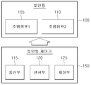
도 1은 본 발명의 실시예에 따른 보안등(100)을 설명하는 블락 다이어그램(block diagram)이다.1 is a block diagram illustrating a
도 1을 참조하면, 보안등(100)은, 제1 조명램프(light lamp)(105) 및 제2 조명램프(110)를 포함한다.Referring to FIG. 1, the
보안등(100)은 조명 또는 방범을 목적으로 골목길 등에 설치된 전등이다. 보안등(100)은 대로변에 일정한 간격에 따라 설치되는 가로등과는 달리 이면 도로나 주택가의 골목과 같이 가로등을 설치하기 어려운 환경에 설치되어 일정한 조도를 야간에도 확보하게 함으로써 통행하는 사람의 안전을 도모하기 위한 조명수단이다.
보안등(100)은, 제1 조명 램프(105)와, 제1 조명 램프(105)의 수명(life)(수명 시간)보다 짧은 수명을 가지고 제1 조명 램프(105)의 시동시간(ignition time)보다 짧은 시동시간을 가지는 제2 조명램프(110)를 포함한다. 상기 시동시간은 제1 조명 램프(105) 또는 제2 조명 램프(110)가 점등할 때까지의 시간을 의미한다.The
제1 조명 램프(105)는 시동시간이 상대적으로 길고(느리고) 수명이 상대적으로 긴 저가의 수은 램프(mercury vapor lamp)일 수 있다. 예를 들어, 수은 램프는 6000시간 이상이고 8000시간 이하의 수명을 가지고 10분의 시동시간을 가질 수 있다.The
제2 조명 램프(110)는 시동시간이 상대적으로 짧고(빠르고) 수명이 상대적으로 짧은 조도가 우수한 HID(high intensity discharge) 램프(고휘도 방전 램프)일 수 있다. 예를 들어, HID(high intensity discharge) 램프는 2000시간 이상이고 3000시간 이하의 수명을 가지고 0.5초의 시동시간을 가질 수 있다. HID 램프의 종류에는 고압 나트륨 램프(high pressure sodium lamp), 메탈 핼라이드 램프(metal halide lamp), 또는 고압 수은 램프(high pressure mercury vapor lamp) 등이 있을 수 있다.The
보안등 제어기(150)는 보안등(100)에 장착(부착)되어 보안등에 전기적 및 기계적으로 연결되고, 점멸 제어 신호에 응답하여 제1 조명 램프(105)의 점멸 및 제2 조명 램프(110)의 점멸을 제어한다. 제1 조명 램프(105)의 점멸 또는 제2 조명램프(110)의 점멸은 센서 네트워크(ubiquitous sensor network)를 통해 무선으로 연결될 수 있는 도 2의 중앙 제어 장치(중앙 제어 서버)(300)에 의해 수행될 수 있다. 보안등(100) 및 보안등 제어기(150)는 골목길 또는 도로의 등주(lamp post)에 설치될 수 있다.The
상기 센서 네트워크는 특정 지역에 소형의 센서 노드들(sensor nodes)(보안등 제어기(150)를 포함하는 다수의 보안등 제어기들)을 설치하여 주변 정보(보안등 제어기들 각각의 센싱(sensing) 정보) 또는 특정 목적의 정보를 획득하여 이를 활용하는 서비스 네트워크를 말한다. 센서 네트워크는 각각의 센서 노드가 특정 목적을 위해 필요한 주변 정보를 센싱하고, 센싱된 정보를 센서 노드간의 무선통신을 이용하여 특정 지점으로 자동화된 방식으로 정보를 전달함으로써 사용자가 센서필드 주변의 정보를 원격으로 수집하여 활용할 수 있는 장점을 가진다. 센서 네트워크는 직렬 통신 방식을 사용하지 않으며, 중간에 하나의 센서 노드가 고장이 있을 경우에도 주변의 다른 센서 노드들과 통신 네트워크를 생성하여 센싱 정보와 같은 데이터를 전송할 수 있다.The sensor network installs small sensor nodes (a plurality of security light controllers including the security light controller 150) in a specific area to detect surrounding information (sensing information of each of the security light controllers). Or a service network that obtains information for a specific purpose and uses it. The sensor network senses the surrounding information necessary for each sensor node for a specific purpose, and transfers the sensed information to a specific point in an automated manner by using wireless communication between the sensor nodes. It has the advantage of being able to collect and utilize remotely. The sensor network does not use a serial communication method, and even when one sensor node fails in the middle, a sensor network may generate a communication network with other sensor nodes nearby to transmit data such as sensing information.
상기 중앙 제어 장치는 보안등 제어기(150)와 함께 센서 네트워크를 구성(형성)하고, 보안등 제어기(150)에 제1 조명 램프(105)의 점멸 및 제2 조명 램프(110)의 점멸을 제어하는 상기 점멸 제어 신호를 송신(제공)한다. 중앙 제어 장치는, 야간에 보안등(100)의 주변을 지나는 통행인 또는 차량이 있음을 센싱(sensing)하는 보안등 제어기(150)의 센싱 정보를 상기 센서 네트워크에 포함되는 통신부(115)를 통해 수신하여 보안등(100)의 점등 시작을 제어할 때 제2 조명 램프(110)가 점등되도록 제어한 후, 제2 조명 램프(110)의 점등시간이 기준시간 값(예를 들어, 15분)보다 클 때 상기 점등된 제2 조명 램프(110)가 소등되고 제1 조명 램프(105)가 점등되도록 제어할 수 있다.The central control unit configures (forms) a sensor network with the
또한, 상기 중앙 제어 장치는 제1 조명 램프(105)가 점등되도록 제어한 후 보안등(100)의 주변을 지나는 통행인 또는 차량이 없음을 센싱하는 보안등 제어기(150)의 센싱 정보를 상기 센서 네트워크를 통해 수신하여 상기 점등된 제1 조명 램프(105)가 소등되도록 제어할 수 있다.In addition, the central control device controls the
전술한 바와 같이, 본 발명에 포함된 보안등(100)에 있어서, 제1 조명 램프(105) 및 제2 조명 램프(110)는 교대로(alternately) 점등되므로, 제1 조명 램프(105)의 사용시간 및 제2 조명 램프(110)의 사용시간이 감소되어 제1 및 제2 조명 램프들(105, 110)의 수명 시간을 고려할 때 제1 및 제2 조명 램프들(105, 110)은 장시간 사용될 수 있다. 특히, 수명 시간이 짧은 제2 조명 램프(110)의 사용시간이 짧게 제한되므로 제2 조명 램프가 장시간 사용될 수 있다. 따라서 본 발명은 제1 및 제2 조명 램프들(105, 110)의 수명이 완료됨에 따라 발생할 수 있는 잦은 램프의 교체를 방지할 수 있다.As described above, in the
보안등 제어기(150)는 통신부(115), 센서부(120), 및 제어부(125)를 포함한다. 통신부(115)는 상기 중앙 제어 장치로부터 상기 점멸 제어 신호를 수신하고, 상기 센서 네트워크를 구성하는 지그비(Zigbee) 통신 모듈을 포함할 수 있다. 센서부(120)는 야간에 보행등(100)의 주변을 지나는 통행인 또는 차량의 열을 감지하여 통행인 또는 차량을 식별(감지)하여 센싱 정보를 생성하는 열 감지 센서를 포함할 수 있다. 열 감지 센서는 예를 들어 적외선 센서 또는 적외선 카메라일 수 있다.The
제어부(125)는 센서부(120)의 센싱 정보를 통신부(115)가 상기 중앙 제어 장치로 정기적으로 송신하도록 제어할 수 있고, 통신부(115)에 수신된 점멸 제어 신호에 응답하여 상기 제1 조명 램프(105)의 점멸 및 제2 조명 램프(110)의 점멸을 제어한다. 제어부(125)는 CPU(central processing unit)의 기능을 수행하고, 보안등 제어기(150)에 포함된 통신부(115) 및 센서부(120)와 같은 구성요소들의 전체적인 동작을 제어한다. 제어부(125)는 내장된 타이머(timer)를 이용하여 제2 조명 램프(110)의 점등 시간을 측정하고 상기 측정된 점등 시간 정보를 통신부(115)를 이용하여 센서 네트워크를 통해 중앙 제어 장치로 전송할 수 있다. 제어부(125)는 중앙제어장치가 위치 정보 요청시 보안등제어기(150)의 ID(identification number) 정보 및 위치 정보를 통신부(115)를 이용하여 센서 네트워크를 통해 중앙 제어 장치로 송신할 수 있다.The
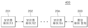
도 2는 본 발명의 실시예에 따른 보안등 제어 시스템(400)을 설명하는 블락 다이어그램이다.2 is a block diagram illustrating a security
도 2를 참조하면, 보안등 제어 시스템(또는 보안등 관리 시스템)(400)은, 다수의 보안등 제어기들(201~20n, n은 2이상의 자연수), 및 중앙 제어 장치(300)를 포함한다. 보안등 제어기들(201~20n)은 일정 지역 범위(예를 들어, 행정구역인 구(區) 범위)에 설치(배치)될 수 있다.Referring to FIG. 2, a security light control system (or security light management system) 400 includes a plurality of security light controllers 201-20n, where n is a natural number of two or more, and a
보안등 제어기들(201~20n) 각각은 도 1의 보안등 제어기(150)에 포함된 구성요소들을 포함하므로, 보안등 제어기들(201~20n) 각각에 대한 설명은 도 1을 참조하여 설명된 보안등 제어기(150)의 설명이 참조될 수 있다. 도 2에 도시되지 않았지만, 보안등 제어기들(201~20n) 각각에는 도 1의 보안등(100)이 장착된다.Since each of the
중앙 제어 장치(300)는 보안등(100)의 설치, 유지, 관리, 및 보수를 수행하는 예를 들어 주민자치센터 또는 구청 또는 시청의 관제 센터(중앙관제센터)에 배치될 수 있다.The
보안등 제어기들(201~20n) 각각은 자신의 통신부를 이용하는 것에 의해, 보안등 제어기들(201~20n)은 센싱 정보를 서로 교환할 수 있다. 상기 센싱 정보는 야간에 보안등 제어기들(201~20n) 각각에 연결된 보안등들 각각의 주변을 지나는 통행인 또는 차량의 존재 여부(존재 유무)를 나타내는 정보를 말한다.Each of the
상기 센싱 정보는 보안등 제어기들(201~20n)을 통해 보안등 제어기들(201~20n)과 함께 센서 네트워크를 구성하는 중앙 제어 장치(300)로 전달될 수 있다. 제n 보안등 제어기(20n)의 경우, 중앙 제어 장치(300)가 자신의 센싱 정보를 요청할 때 자신의 센싱 정보를 다른 보안등 제어기를 거치지 않고 중앙 제어 장치(300)에 직접 송신할 수 있다.The sensing information may be transmitted to the
상기 센서 네트워크는 지그비(Zigbee) 네트워크, WiFi, Bluetooth, 또는 UWB(Ultra Wide Band)와 같은 근거리 무선 센서 네트워크일 수 있다. 지그비 네트워크는 근거리 통신을 지원하는 통신방식으로서 네트워크 내의 객체 노드의 확장이 용이하고, 객체 노드의 대기 전류 소모가 적다. 또한, 지그비는 블루투스(Bluetooth)보다 통신거리가 더 길고, 전력 소모량 또한 상대적으로 적으며, 구축 비용이 저렴하고, 전력 소모량은 무선 인터넷의 1/6 수준에 불과하다.The sensor network may be a short range wireless sensor network such as a Zigbee network, WiFi, Bluetooth, or Ultra Wide Band (UWB). ZigBee network is a communication method that supports short-range communication, and it is easy to extend object nodes in the network, and the standby current consumption of object nodes is low. In addition, ZigBee has a longer communication distance than Bluetooth, relatively low power consumption, low deployment costs, and only one sixth the power of the wireless Internet.
보안등 제어기들(201~20n) 및 중앙 제어 장치(300)가 무선 센서 네트워크(Wireless Sensor Network)인 지그비 보안등 네트워크를 구성(형성)하는 경우, 보안등 제어기들(201~20n) 및 중앙 제어 장치(300) 각각에 포함된 통신부는 지그비 통신 모듈(Zigbee module)을 내장(포함 또는 탑재)한다. 이 때, 보안등 제어기들(201~20n)은 센서 네트워크에서 센서 노드(Sensor Node)(또는 라우터(router))의 역할을 수행하고, 중앙제어장치(300)는 센서 네트워크에서 센서 노드에 의해 감지된 정보(event)를 수집하는 싱크 노드(Sink Node)(또는 코디네이터(coordinator))의 역할을 수행할 수 있다. 라우터는 센싱 정보를 중앙제어장치(300)로 라우팅(routing)하는 역할을 수행하고, 코디네이터는 지그비 네트워크를 형성하고 관리하는 역할을 수행할 수 있다.When the security light controllers 201-20n and the
지그비 기술(지그비 무선 통신 기술)은 홈오토메이션과 데이터 네트워크를 위한 근거리 무선통신 규격으로, IEEE 802.15.4 WPAN(Wireless Personal Area Network) 기술을 기반으로 구성될 수 있으며, 지그비는 저렴한 가격과 저전력, 최대 6만5000 노드까지 늘릴 수 있는 확장성에다 편리한 네트워크 구성, 데이터 오류시 복구가 쉽다는 장점 등을 갖고 있다.ZigBee technology (ZigBee wireless communication technology) is a short-range wireless communication standard for home automation and data networks. It can be configured based on IEEE 802.15.4 Wireless Personal Area Network (WPAN) technology. It has the scalability to increase to 65,000 nodes, convenient network configuration, and easy recovery in case of data failure.
전술한 보안등 제어 시스템(400)에 대해 부연하여 설명하면 다음과 같다. The security
보안등 제어 시스템(400)은, 다수의 보안등(도 1의 100)들, 보안등 제어기들(201~20n), 및 중앙제어장치(300)를 포함한다.The security
상기 보안등들 각각은, 제1 조명 램프와, 제1 조명 램프의 수명보다 짧은 수명을 가지고 상기 제1 조명 램프의 시동시간보다 짧은 시동시간을 가지는 제2 조명 램프를 포함한다.Each of the security lights includes a first lighting lamp and a second lighting lamp having a lifespan shorter than that of the first lighting lamp and having a start time shorter than the start time of the first light lamp.
보안등 제어기들(201~20n) 각각은 상기 보안등들 각각에 대응하여 장착되고, 중앙제어장치(300)의 점멸 제어 신호에 응답하여 보안등들 각각에 포함된 제1 조명 램프의 점멸 및 제2 조명 램프의 점멸을 제어한다.Each of the
중앙 제어 장치(300)는 보안등 제어기들(201~20n)과 함께 센서 네트워크를 구성하고, 보안등 제어기들(201~20n) 각각에 상기 점멸 제어 신호를 송신한다.The
중앙 제어 장치(300)는, 야간에 상기 보안등들 각각의 주변을 지나는 통행인 또는 차량이 있음을 센싱(sensing)하는 보안등 제어기들(201~20n) 각각의 센싱 정보를 상기 센서 네트워크를 통해 수신하여 보안등들의 점등 시작을 제어할 때 제2 조명 램프가 점등되도록 제어한 후, 제2 조명 램프의 점등시간이 기준시간 값(예를 들어, 15분)보다 클 때 상기 점등된 제2 조명 램프가 소등되고 제1 조명 램프가 점등되도록 제어한다. 상기 기준시간 값은 후술하는 도 3의 제어부(315) 내의 메모리 또는 저장부(310)에 저장될 수 있다.The
또한 중앙 제어 장치(300)는 상기 제1 조명 램프가 점등되도록 제어한 후 야간에 상기 보안등들 각각의 주변을 지나는 통행인 또는 차량이 없음을 센싱하는 보안등 제어기들(201~20n) 각각의 센싱 정보를 상기 센서 네트워크를 통해 수신하여 상기 점등된 제1 조명 램프가 소등되도록 제어한다.In addition, the
전술한 바와 같이, 중앙 제어 장치(300)는 보안등 제어기들(201~20n) 각각에 연결된 보안등들 각각에 포함된 제1 조명 램프의 점멸 및 제2 조명 램프의 점멸을 무선으로 원격에서 실시간으로 제어할 수 있다.As described above, the
도 3은 도 2에 도시된 중앙 제어 장치(300)의 실시예를 설명하는 블락 다이어그램이다.3 is a block diagram illustrating an embodiment of the
도 3을 참조하면, 중앙 제어 장치(300)의 실시예는, 통신부(305), 저장부(310), 및 제어부(315)를 포함한다.Referring to FIG. 3, an embodiment of the
통신부(305)는 도 2의 보안등 제어기들(201~20n) 각각으로부터 센싱 정보를 수신한 후 센싱 정보에 대응하는 점멸 제어 신호를 보안등 제어기들(201~20n) 각각으로 송신한다. 상기 센싱 정보는 보안등 제어기들(201~20n) 각각에 연결된 보안등들 각각의 주변을 지나는 통행인 또는 차량의 존재 여부를 지시(indication)하는 정보와, 제2 조명 램프의 점등 시간 정보를 포함할 수 있다. 통신부(305)는 센서 네트워크를 구성하는 지그비 통신 모듈을 포함할 수 있다.The
저장부(310)는 통신부(305)를 통해 보안등 제어기들(201~20n)로부터 수신된 센싱 정보들을 저장할 수 있다. 또한 저장부(310)는 제어부(315)의 센싱 정보에 대한 분석 결과(예를 들어, 시간대별 보안등 주변의 통행인 또는 통행 차량의 수와 같은 통계자료(이전 데이터))를 저장할 수 있다.The
제어부(315)는 CPU(central processing unit)의 기능을 수행하고, 중앙제어장치(300)에 포함된 통신부(305) 및 저장부(310)와 같은 구성요소들의 전체적인 동작을 제어한다.The
제어부(315)는 통신부(305)를 통해 전달되는 센싱 정보들을 분석하는 것에 의해, 보안등 주변의 야간 통행인 또는 야간 통행 차량의 존재 여부를 판단하고, 그 판단 결과에 따라 점멸 제어 신호를 통신부(305)를 통해 보안등 제어기들(201~20n) 각각에 송신(전달)한다.The
제어부(315)는 상기 판단 결과를 중앙 제어 장치(300)의 사용자(관리자)에게 중앙 제어 장치(300)에 포함된(또는 연결된) 디스플레이부(display unit)(미도시)를 통해 보여주도록 디스플레이부를 제어할 수도 있다. 상기 판단 결과에는 점등되는 보안등의 위치 정보 또는 소등되는 보안등의 위치 정보를 포함한다. 따라서 중앙 제어 장치(300)의 사용자는 본 발명을 이용하여 다수의 보안등들을 통합적으로 관리할 수 있다.The
제어부(315)는 센서 네트워크(예를 들어, 지그비 네트워크)에 접속된 보안등 제어기들(201~20n) 각각의 ID(identification number) 정보 및 위치(좌표)를 관리하여 저장부(310)에 저장할 수 있다. 보안등 제어기들(201~20n) 각각은 센서 네트워크를 통해 제어부(315)가 위치 정보 요청시 제어부(315)로 자신의 ID 정보 및 위치 정보를 송출할 수 있다. 제어부(315)는 통신부(305)를 통해 보안등 제어기들(201~20n) 각각의 ID 정보 및 위치 정보를 수신한다.The
본 발명의 다른 실시예에 있어서, 예를 들어, 보안등 제어기(150)에 포함된 센서부(120)가 센싱 정보를 송신한 후 정상적으로 동작하지 않는 경우, 제어부(315)는 내장된 시계를 이용하여 저장부(310)에 이전에 저장시킨 시간대별 보안등 주변의 통행인 또는 통행 차량의 수를 이용하여 보안등에 포함된 제1 및 제2 조명 램프들의 점멸을 제어할 수도 있다. 상기 시간대별 보안등 주변의 통행인 또는 통행 차량의 수에 있어서, 시간대는 보안등 제어기에 포함된 시계에 의해서도 측정될 수 있다.In another embodiment of the present invention, for example, when the
보다 구체적으로 설명하면, 본 발명의 다른 실시예는 도 1, 도 2 및, 도 3을 참조하여 설명한 보안등들, 보안등 제어기들, 및 중앙 제어 장치를 포함한다.More specifically, another embodiment of the present invention includes the security lights, the security light controllers, and the central control apparatus described with reference to FIGS. 1, 2 and 3.
상기 중앙 제어 장치(또는 제어부(315))는, 야간에 보안등들 각각의 주변을 지나는 통행인 또는 차량의 존재 여부를 센싱(sensing)하는 보안등 제어기들 각각의 센싱 정보를 센서 네트워크를 통해 수신하여 분석하는 것에 의해 시간대별 보안등 주변의 통행인 또는 통행 차량의 수를 통계 값으로서 자신의 저장부(310)에 저장한다. 계속하여, 중앙 제어 장치(또는 제어부(315))는, 상기 통계 값이 1 이상인 시간대(time slot)에 제2 조명 램프가 점등되도록 제어한 후 제2 조명 램프의 점등시간이 기준시간 값(예를 들어, 15분)보다 클 때 상기 점등된 제2 조명 램프가 소등되고 제1 조명 램프가 점등되도록 제어하고, 상기 통계 값이 0 인 시간대에 상기 점등된 제1 조명 램프가 소등되도록 제어한다. 즉, 본 발명의 다른 실시예는 이전에 저장된 시간대별 센싱 정보 데이터를 이용하여 현재의 시간대에 대한 제1 조명 램프의 점멸 및 제2 조명 램프의 점멸을 실시간으로 제어할 수 있다. 상기 기준시간 값은 제어부(315) 내의 메모리 또는 저장부(310)에 저장될 수 있다.The central control unit (or the control unit 315) receives sensing information of each of the controllers, such as security sensing the presence of a pedestrian or a vehicle passing through the vicinity of each of the security lamps at night, through the sensor network, and analyzes them. By doing so, the number of pedestrians or vehicles passing by, such as security for each time zone, is stored in its
전술한 바와 같이, 본 발명의 보안등 제어 시스템은 야간에 보안등 주변에 사람의 통행 또는 차량의 통행이 있는 경우에만 보안등을 점등하도록 제어할 수 있으므로, 보안등의 소비전력을 줄일 수 있다.As described above, the security light control system of the present invention can be controlled so as to turn on the security light only when there is a traffic of people or traffic of vehicles around the security light at night, it is possible to reduce the power consumption of the security light.
또한 본 발명은 통행인 또는 차량을 감지(센싱(sensing))하여 보안등을 점등하는 경우 보안등에 포함된 시동시간이 상대적으로 빠른 조명 램프를 이용하므로, 야간에 보안등 주변을 지나는 통행인 또는 차량은 본 발명인 보안등의 조명을 이용할 수 있다.In addition, the present invention uses a relatively fast start-up lamp included in the security light when sensing (sensing) the driver or vehicle to turn on the security light, so that the passer-by or vehicle passing the vicinity of the security light at night is the present inventor. Lighting such as security lights can be used.
보안등 제어 시스템과 가로등 제어 시스템은 동작(작용) 및 구성 등에 있어서 서로 유사하므로, 본 발명은 가로등 제어 시스템에도 적용될 수 있다.Since the security lamp control system and the street lamp control system are similar to each other in operation (action) and configuration, the present invention can be applied to the street lamp control system.
본 실시예에서 사용되는 구성요소 또는 “~부(unit)” 또는 블록 또는 모듈은 메모리 상의 소정 영역에서 수행되는 태스크, 클래스, 서브 루틴, 프로세스, 오브젝트, 실행 쓰레드, 프로그램과 같은 소프트웨어(software)나, FPGA(fieldprogrammable gate array)나 ASIC(application-specific integrated circuit)과 같은 하드웨어(hardware)로 구현될 수 있으며, 또한 상기 소프트웨어 및 하드웨어의 조합으로 이루어질 수도 있다. 상기 구성요소 또는 '~부' 등은 컴퓨터로 판독 가능한 저장 매체에 포함되어 있을 수도 있고, 복수의 컴퓨터에 그 일부가 분산되어 분포될 수도 있다.The components or " units " or blocks or modules used in the present embodiment may be implemented in software such as a task, a class, a subroutine, a process, an object, an execution thread, , A field programmable gate array (FPGA), or an application-specific integrated circuit (ASIC), or a combination of the above software and hardware. The components or parts may be included in a computer-readable storage medium, or a part of the components may be dispersed in a plurality of computers.
이상에서와 같이, 도면과 명세서에서 실시예가 개시되었다. 여기서, 특정한 용어들이 사용되었으나, 이는 단지 본 발명을 설명하기 위한 목적에서 사용된 것이며 의미 한정이나 특허청구범위에 기재된 본 발명의 범위를 제한하기 위하여 사용된 것은 아니다. 그러므로 이 기술분야의 통상의 지식을 가진 자는 본 발명으로부터 다양한 변형 및 균등한 실시예가 가능하다는 점을 이해할 수 있을 것이다. 따라서 본 발명의 진정한 기술적 보호 범위는 첨부된 특허청구범위의 기술적 사상에 의해 정해져야 할 것이다.As described above, the embodiments have been disclosed in the drawings and specification. Although specific terms are used herein, they are used for the purpose of describing the present invention only and are not used to limit the scope of the present invention described in the claims or the claims. It is therefore to be understood by those skilled in the art that various modifications and equivalent embodiments are possible in light of the present invention. Accordingly, the true scope of the present invention should be determined by the technical idea of the appended claims.
105: 제1 조명램프
110: 제2 조명램프
115: 통신부
120: 센서부
150: 보안등 제어기
201~20n: 보안등 제어기들
300: 중앙 제어 장치
305: 통신부
310: 저장부105: first lighting lamp
110: second lighting lamp
115:
120:
150: security light controller
201 ~ 20n: security light controllers
300: central control unit
305:
310: storage unit
Claims (7)
제1 조명 램프와, 상기 제1 조명 램프의 수명보다 짧은 수명을 가지고 상기 제1 조명 램프의 시동시간보다 짧은 시동시간을 가지는 제2 조명 램프를 각각 포함하는 다수의 보안등들;
각각 상기 보안등들 각각에 장착되고, 점멸 제어 신호에 응답하여 상기 보안등들 각각에 포함된 제1 조명 램프의 점멸 및 제2 조명 램프의 점멸을 각각 제어하는 보안등 제어기들; 및
상기 보안등 제어기들과 함께 센서 네트워크를 구성하고, 상기 보안등 제어기들 각각에 상기 점멸 제어 신호를 송신하는 중앙 제어 장치를 포함하며,
상기 중앙 제어 장치는,
야간에 상기 보안등들 각각의 주변을 지나는 통행인 또는 차량이 있음을 센싱(sensing)하는 상기 보안등 제어기들 각각의 센싱 정보를 상기 센서 네트워크를 통해 수신하여 상기 보안등들의 점등 시작을 제어할 때 상기 제2 조명 램프가 점등되도록 제어한 후, 상기 제2 조명 램프의 점등시간이 기준시간 값보다 클 때 상기 점등된 제2 조명 램프가 소등되고 상기 제1 조명 램프가 점등되도록 제어하는 보안등 제어 시스템.In a control system such as security,
A plurality of security lamps each comprising a first lighting lamp and a second lighting lamp having a lifespan shorter than the lifespan of the first lighting lamp and having a startup time shorter than the startup time of the first lighting lamp;
Security light controllers mounted on each of the security lights, respectively, for controlling flashing of the first lighting lamp and flashing of the second lighting lamp included in each of the security lights in response to a flashing control signal; And
A central control unit for constructing a sensor network with the security light controllers and transmitting the flashing control signal to each of the security light controllers,
The central control unit,
The second when receiving the sensing information of each of the security light controllers sensing the presence of a pedestrian or vehicle passing around each of the security lights through the sensor network at night to control the start of lighting of the security lights. And controlling the lighting lamp to be turned on, so that the lit second lighting lamp is turned off and the first lighting lamp is turned on when the lighting time of the second lighting lamp is greater than a reference time value.
상기 중앙 제어 장치는 상기 제1 조명 램프가 점등되도록 제어한 후 야간에 상기 보안등들 각각의 주변을 지나는 통행인 또는 차량이 없음을 센싱하는 상기 보안등 제어기들 각각의 센싱 정보를 상기 센서 네트워크를 통해 수신하여 상기 점등된 제1 조명 램프가 소등되도록 제어하는 보안등 제어 시스템.The method of claim 1,
The central control unit receives the sensing information of each of the security light controllers through the sensor network to sense that there is no pedestrian or vehicle passing through each of the security lights at night after controlling the first lighting lamp to be turned on. And control the lighted first lighting lamp to be turned off.
상기 제1 조명 램프는 수은 램프이고, 상기 제2 조명 램프는 HID(high intensity discharge) 램프인 보안등 제어 시스템.The method of claim 1,
The first lighting lamp is a mercury lamp and the second lighting lamp is a high intensity discharge (HID) lamp.
상기 중앙 제어 장치로부터 상기 점멸 제어 신호를 수신하고, 상기 센서 네트워크를 구성하는 지그비 통신 모듈을 포함하는 통신부;
상기 통행인 또는 상기 차량의 열을 감지하여 상기 통행인 또는 상기 차량을 식별하는 센싱 정보를 생성하는 열 감지 센서를 포함하는 센서부; 및
상기 센서부의 센싱 정보를 상기 통신부가 상기 중앙 제어 장치로 송신하도록 제어하고, 상기 통신부에 수신된 점멸 제어 신호에 응답하여 상기 제1 조명 램프의 점멸 및 상기 제2 조명 램프의 점멸을 제어하는 제어부를 포함하는 보안등 제어 시스템.The method of claim 1, wherein each of the security light controller,
A communication unit including a Zigbee communication module configured to receive the blink control signal from the central control device and configure the sensor network;
A sensor unit including a heat sensor configured to sense heat of the passer-by or the vehicle to generate sensing information for identifying the passer-by or the vehicle; And
A control unit which controls the communication unit to transmit sensing information to the central control unit, and controls the blinking of the first lighting lamp and the blinking of the second lighting lamp in response to a blinking control signal received from the communication unit. Security light control system that includes.
제1 조명 램프와, 상기 제1 조명 램프의 수명보다 짧은 수명을 가지고 상기 제1 조명 램프의 시동시간보다 짧은 시동시간을 가지는 제2 조명 램프를 각각 포함하는 다수의 보안등들;
각각 상기 보안등들 각각에 장착되고, 점멸 제어 신호에 응답하여 상기 보안등들 각각에 포함된 제1 조명 램프의 점멸 및 제2 조명 램프의 점멸을 각각 제어하는 보안등 제어기들; 및
상기 보안등 제어기들과 함께 센서 네트워크를 구성하고, 상기 보안등 제어기들 각각에 상기 점멸 제어 신호를 송신하는 중앙 제어 장치를 포함하며,
상기 중앙 제어 장치는,
야간에 상기 보안등들 각각의 주변을 지나는 통행인 또는 차량의 존재 여부를 센싱(sensing)하는 상기 보안등 제어기들 각각의 센싱 정보를 상기 센서 네트워크를 통해 수신하여 분석하는 것에 의해 시간대별 보안등 주변의 통행인 또는 통행 차량의 수를 통계 값으로 저장하고,
상기 중앙 제어 장치는,
상기 통계 값이 1 이상인 시간대에 상기 제2 조명 램프가 점등되도록 제어한 후 상기 제2 조명 램프의 점등시간이 기준시간 값보다 클 때 상기 점등된 제2 조명 램프가 소등되고 상기 제1 조명 램프가 점등되도록 제어하고, 상기 통계 값이 0 인 시간대에 상기 점등된 제1 조명 램프가 소등되도록 제어하는 보안등 제어 시스템.In a control system such as security,
A plurality of security lamps each comprising a first lighting lamp and a second lighting lamp having a lifespan shorter than the lifespan of the first lighting lamp and having a startup time shorter than the startup time of the first lighting lamp;
Security light controllers mounted on each of the security lights, respectively, for controlling flashing of the first lighting lamp and flashing of the second lighting lamp included in each of the security lights in response to a flashing control signal; And
A central control unit for constructing a sensor network with the security light controllers and transmitting the flashing control signal to each of the security light controllers,
The central control unit,
Passengers around the security lights at night by receiving and analyzing sensing information of each of the security lights controllers sensing the presence or absence of a vehicle at night or through the sensor network. Or store the number of traffic vehicles as a statistical value,
The central control unit,
After the second lighting lamp is controlled to be turned on at a time when the statistical value is 1 or more, when the lighting time of the second lighting lamp is greater than a reference time value, the lit second lighting lamp is turned off and the first lighting lamp is turned off. And controlling the lamp to be turned on and controlling the lit first lamp to be turned off at a time when the statistical value is zero.
상기 제1 조명 램프는 수은 램프이고, 상기 제2 조명 램프는 HID(high intensity discharge) 램프인 보안등 제어 시스템.The method of claim 5,
The first lighting lamp is a mercury lamp and the second lighting lamp is a high intensity discharge (HID) lamp.
상기 중앙 제어 장치로부터 상기 점멸 제어 신호를 수신하고, 상기 센서 네트워크를 구성하는 지그비 통신 모듈을 포함하는 통신부;
상기 통행인 또는 상기 차량의 열을 감지하여 상기 통행인 또는 상기 차량을 식별하는 센싱 정보를 생성하는 열 감지 센서를 포함하는 센서부; 및
상기 센서부의 센싱 정보를 상기 통신부가 상기 중앙 제어 장치로 송신하도록 제어하고, 상기 통신부에 수신된 점멸 제어 신호에 응답하여 상기 제1 조명 램프의 점멸 및 상기 제2 조명 램프의 점멸을 제어하는 제어부를 포함하는 보안등 제어 시스템.The method of claim 5, wherein each of the security light controller,
A communication unit including a Zigbee communication module configured to receive the blink control signal from the central control device and configure the sensor network;
A sensor unit including a heat sensor configured to sense heat of the passer-by or the vehicle to generate sensing information for identifying the passer-by or the vehicle; And
A control unit which controls the communication unit to transmit sensing information to the central control unit, and controls the blinking of the first lighting lamp and the blinking of the second lighting lamp in response to a blinking control signal received from the communication unit. Security light control system that includes.
Priority Applications (1)
| Application Number | Priority Date | Filing Date | Title |
|---|---|---|---|
| KR1020120055204A KR101361715B1 (en) | 2012-05-24 | 2012-05-24 | System capable of controlling security light |
Applications Claiming Priority (1)
| Application Number | Priority Date | Filing Date | Title |
|---|---|---|---|
| KR1020120055204A KR101361715B1 (en) | 2012-05-24 | 2012-05-24 | System capable of controlling security light |
Publications (2)
| Publication Number | Publication Date |
|---|---|
| KR20130131567A true KR20130131567A (en) | 2013-12-04 |
| KR101361715B1 KR101361715B1 (en) | 2014-02-12 |
Family
ID=49980644
Family Applications (1)
| Application Number | Title | Priority Date | Filing Date |
|---|---|---|---|
| KR1020120055204A KR101361715B1 (en) | 2012-05-24 | 2012-05-24 | System capable of controlling security light |
Country Status (1)
| Country | Link |
|---|---|
| KR (1) | KR101361715B1 (en) |
Cited By (1)
| Publication number | Priority date | Publication date | Assignee | Title |
|---|---|---|---|---|
| WO2015140000A1 (en) * | 2014-03-21 | 2015-09-24 | Koninklijke Philips N.V. | Commissioning of remotely managed intelligent lighting devices |
Family Cites Families (3)
| Publication number | Priority date | Publication date | Assignee | Title |
|---|---|---|---|---|
| JP3961165B2 (en) * | 1999-09-13 | 2007-08-22 | 松下電工株式会社 | Lighting device |
| KR101021224B1 (en) * | 2008-09-30 | 2011-03-11 | 주식회사 필엔지 | Led street light |
| KR101044224B1 (en) * | 2010-12-20 | 2011-06-24 | 스티브에스 김 | Vehicle detection control system and method for hybrid street lamps |
-
2012
- 2012-05-24 KR KR1020120055204A patent/KR101361715B1/en active IP Right Grant
Cited By (4)
| Publication number | Priority date | Publication date | Assignee | Title |
|---|---|---|---|---|
| WO2015140000A1 (en) * | 2014-03-21 | 2015-09-24 | Koninklijke Philips N.V. | Commissioning of remotely managed intelligent lighting devices |
| JP2017508262A (en) * | 2014-03-21 | 2017-03-23 | フィリップス ライティング ホールディング ビー ヴィ | Commissioning of remotely managed intelligent lighting devices |
| US10262527B2 (en) | 2014-03-21 | 2019-04-16 | Signify Holding B.V. | Commissioning of remotely managed intelligent lighting devices |
| EP3120069B1 (en) | 2014-03-21 | 2022-05-11 | Signify Holding B.V. | Commissioning of remotely managed intelligent lighting devices |
Also Published As
| Publication number | Publication date |
|---|---|
| KR101361715B1 (en) | 2014-02-12 |
Similar Documents
| Publication | Publication Date | Title |
|---|---|---|
| KR102060572B1 (en) | DIMMING CONTROL SYSTEM OF LED STREETLIGHT AND SECURITY LIGHT BASED ON IoT | |
| US9210759B2 (en) | Luminaire with ambient sensing and autonomous control capabilities | |
| Leccese et al. | Intelligent wireless street lighting system | |
| US10098212B2 (en) | Systems and methods for controlling outdoor luminaire wireless network using smart appliance | |
| Yoshiura et al. | Smart street light system looking like usual street lights based on sensor networks | |
| KR102135598B1 (en) | IoT based intelligent street light control system | |
| KR101889875B1 (en) | Low installation type low power smart street lamp system | |
| KR101286806B1 (en) | LED lamp control system using smart phone | |
| CN103917019B (en) | A kind of street lamp control system based on Internet of Things | |
| EP2262350A1 (en) | Lighting unit, network of lighting units and method for controlling the light intensity of a lighting network comprising at least one lighting unit | |
| KR101236186B1 (en) | System for controlling streetlight and remote controller thereof | |
| Parekar et al. | An intelligent system for monitoring and controlling of street light using GSM technology | |
| KR20130142612A (en) | Street lamp control system using wiress mesh network | |
| JP2012004062A (en) | Street light group system | |
| US11375599B2 (en) | Systems and methods for outdoor luminaire wireless control | |
| KR20120114510A (en) | Intelligently safety lighting system | |
| KR20180083741A (en) | Indoor car park lighting system | |
| CN104470035A (en) | Road lighting intelligent power source system | |
| KR101361715B1 (en) | System capable of controlling security light | |
| KR20080091946A (en) | A fuzzy control device of street lighting | |
| KR102119669B1 (en) | Apparatus of remote streetlamp control and method thereof by centralized solar system based on big data | |
| KR100281222B1 (en) | Wire / wireless transmission street light controller | |
| KR101246671B1 (en) | Lighting system accooroding to wireless sensor network and lighting control method thereof | |
| KR102034351B1 (en) | Light System And Control Method Of The Same | |
| KR20160125697A (en) | Apparatus and for controlling street lamp and control server |
Legal Events
| Date | Code | Title | Description |
|---|---|---|---|
| A201 | Request for examination | ||
| E902 | Notification of reason for refusal | ||
| E701 | Decision to grant or registration of patent right | ||
| GRNT | Written decision to grant | ||
| FPAY | Annual fee payment |
Payment date: 20170405 Year of fee payment: 4 |
|
| FPAY | Annual fee payment |
Payment date: 20180201 Year of fee payment: 5 |
|
| FPAY | Annual fee payment |
Payment date: 20190130 Year of fee payment: 6 |