KR20130128974A - Wind deflector installation structure of bridge wing - Google Patents
Wind deflector installation structure of bridge wing Download PDFInfo
- Publication number
- KR20130128974A KR20130128974A KR1020120053227A KR20120053227A KR20130128974A KR 20130128974 A KR20130128974 A KR 20130128974A KR 1020120053227 A KR1020120053227 A KR 1020120053227A KR 20120053227 A KR20120053227 A KR 20120053227A KR 20130128974 A KR20130128974 A KR 20130128974A
- Authority
- KR
- South Korea
- Prior art keywords
- wind deflector
- bridge
- bridge wing
- installation structure
- wing
- Prior art date
- Legal status (The legal status is an assumption and is not a legal conclusion. Google has not performed a legal analysis and makes no representation as to the accuracy of the status listed.)
- Withdrawn
Links
- 238000009434 installation Methods 0.000 title claims description 16
- 230000004888 barrier function Effects 0.000 claims description 23
- 238000000034 method Methods 0.000 claims 2
- 230000001681 protective effect Effects 0.000 abstract 1
- 238000007664 blowing Methods 0.000 description 5
- 238000012544 monitoring process Methods 0.000 description 2
- 230000004308 accommodation Effects 0.000 description 1
- 239000000969 carrier Substances 0.000 description 1
- 239000000470 constituent Substances 0.000 description 1
- 238000010411 cooking Methods 0.000 description 1
- 238000007599 discharging Methods 0.000 description 1
- 239000000463 material Substances 0.000 description 1
Images


Classifications
-
- B—PERFORMING OPERATIONS; TRANSPORTING
- B63—SHIPS OR OTHER WATERBORNE VESSELS; RELATED EQUIPMENT
- B63B—SHIPS OR OTHER WATERBORNE VESSELS; EQUIPMENT FOR SHIPPING
- B63B15/00—Superstructures, deckhouses, wheelhouses or the like; Arrangements or adaptations of masts or spars, e.g. bowsprits
-
- B—PERFORMING OPERATIONS; TRANSPORTING
- B63—SHIPS OR OTHER WATERBORNE VESSELS; RELATED EQUIPMENT
- B63B—SHIPS OR OTHER WATERBORNE VESSELS; EQUIPMENT FOR SHIPPING
- B63B17/00—Vessels parts, details, or accessories, not otherwise provided for
- B63B17/02—Awnings, including rigid weather protection structures, e.g. sunroofs; Tarpaulins; Accessories for awnings or tarpaulins
Landscapes
- Chemical & Material Sciences (AREA)
- Engineering & Computer Science (AREA)
- Combustion & Propulsion (AREA)
- Mechanical Engineering (AREA)
- Ocean & Marine Engineering (AREA)
- Bridges Or Land Bridges (AREA)
Abstract
Description
본 발명은 선박의 브릿지 윙의 윈드 디플렉터 설치구조에 관한 것으로서 보다 상세하게는 조타실에서 바라본 사이드 시야각을 방해하지 않으면서도 윈드 디플렉터의 기능을 그대로 유지하도록 하는 선박의 브릿지 윙의 윈드 디플렉터 설치구조에 관한 것이다.
The present invention relates to a wind deflector installation structure of a bridge wing of a ship, and more particularly to a wind deflector installation structure of a bridge wing of a ship to maintain the function of the wind deflector without disturbing the side viewing angle viewed from the steering chamber. .
유조선이나 LNG 수송선은 선박 중앙에 선박 대부분을 점유하는 탱크를 격납하는 화물구역이 있고, 보통 선미에 선원거주구역, 기관실 및 브릿지 등이 배치되어 있다.Oil tankers and LNG carriers have a cargo area in the center of the ship that contains the tanks that occupy most of the ship, and usually have a crew resident area, engine room and bridge at the stern.
상기 브릿지(bridge)는 선박운항을 조종하는 곳으로 선교(船橋) 또는 함교(艦橋)라 부르기도 하는데, 선미에 타워형으로 위치하고 있다.The bridge is called a bridge or bridge as a place to operate a ship operation, and is located at the stern as a tower.
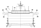
도 1은 종래 일반적인 LNG 선박의 브릿지 부분을 도시한 개략도이다.1 is a schematic view showing a bridge portion of a conventional general LNG vessel.
도시된 바와 같이 선박의 기관실(미도시)이 선박 저부에 배치되고, 상기 기관실 위에는 선원이 거주하도록 업무공간, 취사, 휴식 및 취침공간이 구비된 다수층의 거주구역(accommodation block, 1)이 타워형으로 설치되며, 상기 거주구역(1) 상단에 각종 항해장비, 통신장비, 조타장비가 배치된 조타실을 포함하는 브릿지(10)가 있다.As shown in the drawing, an engine room (not shown) of a ship is disposed at the bottom of the ship, and a multi-storey accommodation block (1) having a work space, cooking, rest, and sleeping spaces for the crew's residence is located above the engine room. Is installed as, there is a bridge (10) including a steering room on which the various navigation equipment, communication equipment, steering equipment is arranged on the living area (1).
상기 브릿지(10) 양측으로 캔틸레버(cantilever)와 같이 길게 돌출된 구조물이 선체의 측면까지 연장되어 있는데, 이러한 구조물은 날개와 같은 모양을 가지므로 브릿지 윙(bridge wing, 20)이라 한다.A structure that protrudes long like a cantilever on both sides of the
이러한 브릿지 윙(20)은 브릿지(10)에서 선체의 좌우측편을 감시하기 위한 구조물로서 선원이 지나다닐 수 있도록 통로가 구비되어 있으며 자중에 의한 처짐이나 외력에 의한 진동을 방지하도록 도시된 바와 같이 테이퍼진 형상을 가지거나 별도의 지지대가 구비될 수도 있다.The
도 2는 종래기술의 브릿지 윙 및 윈드 디플렉터 설치구조를 도시한 평면도이고, 도 3은 종래기술의 윈드 디플렉터 설치구조를 도시한 측단면도이다.2 is a plan view showing a bridge wing and a wind deflector installation structure of the prior art, Figure 3 is a side cross-sectional view showing a wind deflector installation structure of the prior art.
도 2, 3을 참조하며, 브릿지 윙(20) 둘레에는 방호벽(30)이 설치되며, 특히 선원이 주로 활동하는 관측지점에는 관측자의 상체로 불어오는 맞바람을 상쇄시키는 역할을 하는 윈드 디플렉터(40)가 더 설치된다.Referring to FIGS. 2 and 3, a
상기 방호벽(30)은 관측자의 허리에서 가슴 높이 정도로 형성된다. 이때, 상기 방호벽(30) 상부는 관측자의 시야 확보를 위해 개방되도록 하고 있다.The
이때, 방호벽(30)의 상부로 불어오는 바람에 의한 영향을 상쇄시키기 위한 역할을 윈드 디플렉터(40)가 하게 된다.At this time, the
상기 윈드 디플렉터(40)는 도 3에서 보는 바와 같이 방호벽(30) 상단에 설치되는데, 방호벽(30)에 부딪힌 바람이 수직방향으로 꺽여져 상승 토출되도록 안내하는 노즐구조를 제공한다.The
이와 같은 윈드 디플렉터(40)는 하부의 유입구 측이 넓고 상부의 토출구 측이 좁은 형태로 이루어져 있어, 토출구 측에서 빠른 유속의 바람을 토출하게 된다.Such a
이때, 토출되는 바람은 관측자의 상체로 불어오는 바람의 영향을 차단시켜주는 에어커튼으로서의 역할을 하게 된다.At this time, the discharged wind serves as an air curtain to block the influence of the wind blowing into the upper body of the observer.
그러나, 이와 같은 역할을 하는 윈드 디플렉터(40)는 브릿지 윙(20)의 전방으로 돌출되는 형태로 설치됨으로써, 조타실에서 바라보았을 때, 사이드 시야각을 방해하는 장애물로서 시야확보에 어려움을 겪는 문제가 있었다.
However, the
종래기술의 문제점을 해결하기 위해 안출된 본 발명의 목적은 조타실에서 바라본 사이드 시야각을 방해하지 않으면서도 윈드 디플렉터의 기능을 그대로 유지하도록 하는 선박의 브릿지 윙의 윈드 디플렉터 설치구조를 제공함에 있다.
An object of the present invention devised to solve the problems of the prior art is to provide a wind deflector installation structure of the bridge wing of the ship to maintain the function of the wind deflector without disturbing the side viewing angle seen from the steering room.
본 발명의 일측면에 따르면, 브릿지 윙 선단으로부터 통행로 내측으로 기울어진 경사형 방호벽을 형성하고, 상기 경사형 방호벽 상부에 윈드 디플렉터를 설치하되, 상기 윈드 디플렉터가 브릿지 윙의 통행로 내측에 위치되도록 하는 것을 특징으로 하는 선박의 브릿지 윙의 윈드 디플렉터 설치구조가 제공될 수 있다.According to one aspect of the present invention, to form a sloped inclined barrier inclined from the end of the bridge wing to the inside of the passage, and to install a wind deflector on top of the inclined barrier, so that the wind deflector is located inside the passage of the bridge wing A wind deflector installation structure of a bridge wing of a ship may be provided.
여기서, 상기 경사형 방호벽은 임의의 수직선을 기준으로 했을 때, 내측방향으로 10~30도 기울어진 것을 특징으로 한다.Here, the inclined firewall is characterized in that inclined 10 to 30 degrees in the inner direction when based on any vertical line.
또한, 상기 윈드 디플렉터는 횡방향으로 연장되는 슬릿노즐 형태인 것을 특징으로 한다.
In addition, the wind deflector is characterized in that the slit nozzle shape extending in the transverse direction.
본 발명은 브릿지 윙 선단으로부터 통행로 내측으로 기울어진 경사형 방호벽을 형성하고, 상기 경사형 방호벽 상부에 윈드 디플렉터를 설치하되, 상기 윈드 디플렉터가 브릿지 윙의 통행로 내측에 위치되도록 함으로써, 조타실에서 바라본 사이드 시야각을 방해하지 않으면서도 윈드 디플렉터의 기능을 그대로 유지하도록 하는 효과를 갖는다.
The present invention forms an inclined barrier wall inclined from the bridge wing tip to the inside of the passageway, and installs a wind deflector on the inclined barrier wall, so that the wind deflector is located inside the passageway of the bridge wing, so that the side viewing angle viewed from the steering chamber It has the effect of keeping the function of the wind deflector intact without disturbing it.
도 1은 일반적인 LNG 선박의 브릿지 부분을 도시한 개략도.
도 2는 종래기술의 브릿지 윙 및 윈드 디플렉터 설치구조를 도시한 평면도.
도 3은 종래기술의 윈드 디플렉터 설치구조를 도시한 측단면도.
도 4는 본 발명에 따른 브릿지 윙 및 윈드 디플렉터 설치구조를 도시한 평면도.
도 5는 본 발명에 따른 윈드 디플렉터 설치구조를 도시한 측단면도.1 is a schematic view showing a bridge portion of a typical LNG vessel.
Figure 2 is a plan view showing a bridge wing and a wind deflector installation structure of the prior art.
Figure 3 is a side cross-sectional view showing a wind deflector installation structure of the prior art.
Figure 4 is a plan view showing a bridge wing and wind deflector installation structure according to the present invention.
Figure 5 is a side cross-sectional view showing a wind deflector installation structure according to the present invention.
이하, 본 발명의 바람직한 실시예에 대해 첨부된 도면을 참조하여 자세히 설명하면 다음과 같다.Hereinafter, preferred embodiments of the present invention will be described in detail with reference to the accompanying drawings.
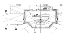
도 4는 본 발명에 따른 브릿지 윙 및 윈드 디플렉터 설치구조를 도시한 평면도이고, 도 5는 본 발명에 따른 윈드 디플렉터 설치구조를 도시한 측단면도이다.4 is a plan view showing a bridge wing and a wind deflector installation structure according to the present invention, Figure 5 is a side cross-sectional view showing a wind deflector installation structure according to the present invention.
도 4, 5를 참조하면, 거주구역 상단에 각종 항해장비, 통신장비, 조타장비가 배치된 조타실을 포함하는 브릿지(110)가 구비된다.4 and 5, a
이때, 상기 브릿지(110) 양측으로는 날개와 같은 모양으로 길게 돌출된 브릿지 윙(120)이 형성된다. 이러한 브릿지 윙(120)은 브릿지(110)에서 선체의 좌우측편을 감시하기 위한 구조물로서 선원이 지나다닐 수 있도록 통로가 구비된다.At this time, both sides of the
상기 브릿지 윙(120) 둘레에는 브릿지 윙(120) 선단으로부터 통행로 내측으로 기울어진 경사형 방호벽(130)을 형성하고, 상기 경사형 방호벽(130) 상부에는 윈드 디플렉터(140)가 설치된다.The
이때, 상기 윈드 디플렉터(140)는 브릿지 윙(120)의 통행로 내측에 위치되도록 하는 것이 바람직하다.In this case, the
또한, 상기 경사형 방호벽(130)은 임의의 수직선을 기준으로 했을 때, 내측방향으로 10~30도 기울어진 형태로 제작된다.
In addition, the
또한, 상기 윈드 디플렉터는 횡방향으로 연장되는 슬릿노즐 형태로 제작될 수 있다.In addition, the wind deflector may be manufactured in the form of a slit nozzle extending in the transverse direction.
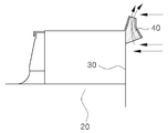
상기 방호벽(130)은 관측자의 허리에서 가슴 높이 정도로 형성된다. 이때, 상기 방호벽(130) 상부는 관측자의 시야 확보를 위해 개방되도록 한다.The
이때, 방호벽(130)의 상부로 불어오는 바람에 의한 영향을 상쇄시키기 위한 역할을 윈드 디플렉터(140)가 하게 된다.At this time, the
상기 윈드 디플렉터(140)는 방호벽(130) 상단에 설치되는데, 방호벽(130)에 부딪힌 바람이 수직방향으로 꺽여져 상승 토출되도록 안내하는 노즐구조를 제공한다.The
이때, 상기 윈드 디플렉터(140)는 하부의 유입구 측이 넓고 상부의 토출구 측이 좁은 형태로 이루어져 있어, 토출구 측에서 빠른 유속의 바람을 토출하게 된다.At this time, the
이때, 토출되는 바람은 관측자의 상체로 불어오는 바람의 영향을 차단시켜주는 에어커튼으로서의 역할을 하게 된다.At this time, the discharged wind serves as an air curtain to block the influence of the wind blowing into the upper body of the observer.
특히, 본 발명은 방호벽(130)이 경사면을 형성함으로써, 방호벽(130)에 부딪힌 바람이 자연스럽게 상부쪽으로 유도됨으로써, 보다 많은 양의 바람을 윈드 디플렉터(140) 쪽으로 유도할 수 있게 되어, 토출측의 풍압을 상승시키는 효과를 갖게 된다.
In particular, the present invention by forming the inclined surface of the
본 발명은 브릿지 윙 선단으로부터 통행로 내측으로 기울어진 경사형 방호벽을 형성하고, 상기 경사형 방호벽 상부에 윈드 디플렉터를 설치하되, 상기 윈드 디플렉터가 브릿지 윙의 통행로 내측에 위치되도록 함으로써, 조타실에서 바라본 사이드 시야각을 방해하지 않으면서도 윈드 디플렉터의 기능을 그대로 유지하도록 하는 효과를 갖는다.The present invention forms an inclined barrier wall inclined from the bridge wing tip to the inside of the passageway, and installs a wind deflector on the inclined barrier wall, so that the wind deflector is located inside the passageway of the bridge wing, so that the side viewing angle viewed from the steering chamber It has the effect of keeping the function of the wind deflector intact without disturbing it.
이상 첨부된 도면을 참조하여 본 발명의 실시예를 설명하였지만, 본 발명이 속하는 기술분야에서 통상의 지식을 가진 자는 본 발명이 그 기술적 사상이나 필수적인 특징을 변경하지 않고서 다른 구체적인 형태로 실시될 수 있다는 것을 이해할 수 있을 것이다. 예를 들어 당업자는 각 구성요소의 재질, 크기 등을 적용 분야에 따라 변경하거나, 실시형태들을 조합 또는 치환하여 본 발명의 실시예에 명확하게 개시되지 않은 형태로 실시할 수 있으나, 이 역시 본 발명의 범위를 벗어나지 않는 것이다. 그러므로 이상에서 기술한 실시예는 모든 면에서 예시적인 것으로 한정적인 것으로 이해해서는 안되며, 이러한 변형된 실시예는 본 발명의 특허청구범위에 기재된 기술사상에 포함된다고 하여야 할 것이다.
While the present invention has been described in connection with what is presently considered to be practical exemplary embodiments, it is to be understood that the invention is not limited to the disclosed embodiments, but, on the contrary, You will understand. For example, a person skilled in the art can change the material, size and the like of each constituent element depending on the application field or can combine or substitute the embodiments in a form not clearly disclosed in the embodiment of the present invention, Of the range. Therefore, it should be understood that the above-described embodiments are to be considered in all respects as illustrative and not restrictive, and that such modified embodiments are included in the technical idea described in the claims of the present invention.
1: 거주구역
10, 110: 브릿지
20, 120: 브릿지 윙
30, 130: 방호벽
40, 140: 윈드 디플렉터1: residence
10, 110: bridge
20, 120: bridge wing
30, 130: firewall
40, 140: wind deflector
Claims (3)
A sloped barrier wall inclined from the tip of the bridge wing to the inside of the passageway is formed, and a wind deflector is installed on the sloped barrier wall, so that the wind deflector is positioned inside the passageway of the bridge wing. Wind deflector installation structure.
상기 경사형 방호벽은 임의의 수직선을 기준으로 했을 때, 내측방향으로 10~30도 기울어진 것을 특징으로 하는 선박의 브릿지 윙의 윈드 디플렉터 설치구조.
The method of claim 1,
The inclined barrier wall is a wind deflector installation structure of the bridge wing of the ship, characterized in that inclined 10 to 30 degrees in the inner direction, based on any vertical line.
상기 윈드 디플렉터는 횡방향으로 연장되는 슬릿노즐 형태인 것을 특징으로 하는 선박의 브릿지 윙의 디플렉터 설치구조. The method of claim 1,
The wind deflector is a deflector installation structure of the bridge wing of the ship, characterized in that the slit nozzle shape extending in the transverse direction.
Priority Applications (1)
| Application Number | Priority Date | Filing Date | Title |
|---|---|---|---|
| KR1020120053227A KR20130128974A (en) | 2012-05-18 | 2012-05-18 | Wind deflector installation structure of bridge wing |
Applications Claiming Priority (1)
| Application Number | Priority Date | Filing Date | Title |
|---|---|---|---|
| KR1020120053227A KR20130128974A (en) | 2012-05-18 | 2012-05-18 | Wind deflector installation structure of bridge wing |
Publications (1)
| Publication Number | Publication Date |
|---|---|
| KR20130128974A true KR20130128974A (en) | 2013-11-27 |
Family
ID=49855945
Family Applications (1)
| Application Number | Title | Priority Date | Filing Date |
|---|---|---|---|
| KR1020120053227A Withdrawn KR20130128974A (en) | 2012-05-18 | 2012-05-18 | Wind deflector installation structure of bridge wing |
Country Status (1)
| Country | Link |
|---|---|
| KR (1) | KR20130128974A (en) |
Cited By (2)
| Publication number | Priority date | Publication date | Assignee | Title |
|---|---|---|---|---|
| KR101880475B1 (en) * | 2017-08-03 | 2018-07-20 | 우종화 | wind deflector |
| WO2024154187A1 (en) * | 2023-01-16 | 2024-07-25 | 川崎重工業株式会社 | Liquefied gas transport vessel |
-
2012
- 2012-05-18 KR KR1020120053227A patent/KR20130128974A/en not_active Withdrawn
Cited By (2)
| Publication number | Priority date | Publication date | Assignee | Title |
|---|---|---|---|---|
| KR101880475B1 (en) * | 2017-08-03 | 2018-07-20 | 우종화 | wind deflector |
| WO2024154187A1 (en) * | 2023-01-16 | 2024-07-25 | 川崎重工業株式会社 | Liquefied gas transport vessel |
Similar Documents
| Publication | Publication Date | Title |
|---|---|---|
| PH12014502052B1 (en) | Marine vessel | |
| WO2007124407A3 (en) | Extended coverage horizontal sidewall sprinkler | |
| US11219790B2 (en) | Long-throw fire protection sprinkler | |
| KR20130128974A (en) | Wind deflector installation structure of bridge wing | |
| JP2013199204A (en) | Ship | |
| KR20130007061U (en) | Wind deflector Installation structure of bridge wing | |
| KR101869012B1 (en) | Antifreezing Device for Forest Firefighting Water | |
| CN104058194B (en) | Air pipe head and the method for being discharged or being allowed liquid to flow out to tank | |
| CN205713834U (en) | Naval vessel is with pneumatic anti-water cannon device shutter | |
| KR101444504B1 (en) | Drillship having block in moonpool for preventing vortex with concave type flow stabilizer part | |
| EP2543587A1 (en) | Invasion preventing apparatus for ship | |
| KR20150001219U (en) | Wind deflector and vessel comprising the same | |
| CN205524816U (en) | Bulwark structure of keeping out wind of platform is observed to boats and ships | |
| NO333988B1 (en) | Fire extinguishing unit for converting a liquid into a liquid mist | |
| KR20130000680U (en) | Dual structure pipe | |
| TWI683686B (en) | Fire extinguishing equipment | |
| KR20150091649A (en) | Hull-Duct and Ventilation System of Machinery Room for FLNG Marine Vessel Using The Same | |
| KR20110005493A (en) | Bridge wing support | |
| WO2019061805A1 (en) | Ship side light box and ship having same | |
| CN103170079A (en) | Water spray head | |
| JP2015019889A (en) | Fire extinguishing equipment for parking lots | |
| JP5165510B2 (en) | Vent pipe in storage tank | |
| KR20070039021A (en) | Fire tarpaulin with guide vane | |
| KR101732095B1 (en) | Tunnel having cooling system of water-spraying type using finishing material of fireproof function and water storage function, and construction method for the same | |
| US10612815B2 (en) | Stepped damper |
Legal Events
| Date | Code | Title | Description |
|---|---|---|---|
| PA0109 | Patent application |
Patent event code: PA01091R01D Comment text: Patent Application Patent event date: 20120518 |
|
| PG1501 | Laying open of application | ||
| PC1203 | Withdrawal of no request for examination | ||
| WITN | Application deemed withdrawn, e.g. because no request for examination was filed or no examination fee was paid |