KR20130127646A - Plant cultivation apparatus having water diffusion supply unit - Google Patents
Plant cultivation apparatus having water diffusion supply unit Download PDFInfo
- Publication number
- KR20130127646A KR20130127646A KR1020120051319A KR20120051319A KR20130127646A KR 20130127646 A KR20130127646 A KR 20130127646A KR 1020120051319 A KR1020120051319 A KR 1020120051319A KR 20120051319 A KR20120051319 A KR 20120051319A KR 20130127646 A KR20130127646 A KR 20130127646A
- Authority
- KR
- South Korea
- Prior art keywords
- water
- planting
- main body
- unit
- plants
- Prior art date
Links
Images


Classifications
-
- A—HUMAN NECESSITIES
- A01—AGRICULTURE; FORESTRY; ANIMAL HUSBANDRY; HUNTING; TRAPPING; FISHING
- A01G—HORTICULTURE; CULTIVATION OF VEGETABLES, FLOWERS, RICE, FRUIT, VINES, HOPS OR SEAWEED; FORESTRY; WATERING
- A01G7/00—Botany in general
- A01G7/04—Electric or magnetic or acoustic treatment of plants for promoting growth
- A01G7/045—Electric or magnetic or acoustic treatment of plants for promoting growth with electric lighting
-
- A—HUMAN NECESSITIES
- A01—AGRICULTURE; FORESTRY; ANIMAL HUSBANDRY; HUNTING; TRAPPING; FISHING
- A01G—HORTICULTURE; CULTIVATION OF VEGETABLES, FLOWERS, RICE, FRUIT, VINES, HOPS OR SEAWEED; FORESTRY; WATERING
- A01G27/00—Self-acting watering devices, e.g. for flower-pots
- A01G27/008—Component parts, e.g. dispensing fittings, level indicators
-
- A—HUMAN NECESSITIES
- A01—AGRICULTURE; FORESTRY; ANIMAL HUSBANDRY; HUNTING; TRAPPING; FISHING
- A01G—HORTICULTURE; CULTIVATION OF VEGETABLES, FLOWERS, RICE, FRUIT, VINES, HOPS OR SEAWEED; FORESTRY; WATERING
- A01G27/00—Self-acting watering devices, e.g. for flower-pots
- A01G27/02—Self-acting watering devices, e.g. for flower-pots having a water reservoir, the main part thereof being located wholly around or directly beside the growth substrate
-
- A—HUMAN NECESSITIES
- A01—AGRICULTURE; FORESTRY; ANIMAL HUSBANDRY; HUNTING; TRAPPING; FISHING
- A01G—HORTICULTURE; CULTIVATION OF VEGETABLES, FLOWERS, RICE, FRUIT, VINES, HOPS OR SEAWEED; FORESTRY; WATERING
- A01G9/00—Cultivation in receptacles, forcing-frames or greenhouses; Edging for beds, lawn or the like
- A01G9/02—Receptacles, e.g. flower-pots or boxes; Glasses for cultivating flowers
-
- A—HUMAN NECESSITIES
- A01—AGRICULTURE; FORESTRY; ANIMAL HUSBANDRY; HUNTING; TRAPPING; FISHING
- A01G—HORTICULTURE; CULTIVATION OF VEGETABLES, FLOWERS, RICE, FRUIT, VINES, HOPS OR SEAWEED; FORESTRY; WATERING
- A01G9/00—Cultivation in receptacles, forcing-frames or greenhouses; Edging for beds, lawn or the like
- A01G9/20—Forcing-frames; Lights, i.e. glass panels covering the forcing-frames
-
- A—HUMAN NECESSITIES
- A01—AGRICULTURE; FORESTRY; ANIMAL HUSBANDRY; HUNTING; TRAPPING; FISHING
- A01G—HORTICULTURE; CULTIVATION OF VEGETABLES, FLOWERS, RICE, FRUIT, VINES, HOPS OR SEAWEED; FORESTRY; WATERING
- A01G9/00—Cultivation in receptacles, forcing-frames or greenhouses; Edging for beds, lawn or the like
- A01G9/24—Devices or systems for heating, ventilating, regulating temperature, illuminating, or watering, in greenhouses, forcing-frames, or the like
- A01G9/247—Watering arrangements
Abstract
Description
본 발명은 식물 재배기에 관한 것으로서, 보다 상세하게는 식물이 요구되는 식재 환경에 따라 효율적으로 식재할 수 있는 물분사부를 가지는 식물 재배기에 관한 것이다.The present invention relates to a plant cultivator, and more particularly, to a plant cultivator having a water spraying section capable of efficiently planting the plant according to the required planting environment.
일반적으로, 가정이나 사무실을 비롯하여 다양한 실내 또는 실외에서 꽃이나 나무 등의 식물을 대지로부터 독립적으로 가꾸기 위하여 여러 가지의 형태와 디자인을 가진 화분을 이용하게 된다.In general, pots having various shapes and designs are used to independently decorate plants such as flowers or trees from home or office and various indoor or outdoor areas.
이러한 화분은 대개 식물이 식재된 상태로 구입하거나, 화분을 별도로 구입하여 원하는 식물을 식재하게 되는데, 화분에 식재된 식물은 광합성을 통해서 영양을 얻게 되므로, 식물이 제대로 성장하기 위해서 빛과 수분 등의 공급이 중요하다.These pots are usually purchased in a state where plants are planted or purchased separately to plant desired plants. Plants planted in pots are nourished through photosynthesis, so that plants can grow properly such as light and moisture. Supply is important.
한편, 화분에 원하는 씨앗을 심어서 발아되도록 하기 위해서는 먼저 흙을 파서 씨앗이 흙 속에 묻히도록 한 다음, 수분을 공급하면서 일정 시간을 기다리면 발아하게 된다.On the other hand, in order to plant the desired seeds in the pot to germinate, so that the seeds are buried in the soil first, then wait for a certain time while supplying moisture will germinate.
그러나, 종래의 화분은 식물의 광합성 등을 위하여 햇빛이 드는 곳에 설치해야 하는 등의 제약이 따르게 되고, 이로 인해 식물은 장소에 크게 영향을 받을 뿐만 아니라, 주기적인 관리 소홀로 인해 식물의 성장이 제대로 이루어지지 못하게 되는 문제점을 가지고 있었다. 이는 식물이 토양을 필요로 하는 경우는 물론 수생인 경우에도 동일하게 적용된다. 또한, 종래의 화분은 배수 등에 의해 흙이 물과 함께 배출되어 화분받침대를 설치한다고 하더라도 주변을 오염시키는 문제점을 가지고 있었다.However, the conventional pollen is subject to restrictions such as that it should be installed in a place where it is exposed to sunlight for photosynthesis of plants and the like. Therefore, not only the plant is greatly affected by the place but also the plant growth It is not possible to achieve this. This applies equally to aquatic as well as when plants need soil. In addition, the conventional pollen has a problem of polluting the surroundings, even if the soil is discharged together with the water by drainage, such as to install a pot stand.
이러한 문제점을 해결하기 위하여, 실내에서 식물을 재배하도록 하는 식물 재배기의 개발이 필요하게 되었는데, 이 경우 식물 재배기에 재배되는 식물에 물을 안정적으로 공급하기 위한 장치의 개발이 필요하게 되었다.In order to solve this problem, it is necessary to develop a plant grower to grow plants indoors, in which case it is necessary to develop a device for stably supplying water to the plants grown in the plant grower.
상기한 바와 같은 종래의 문제점을 해결하기 위하여, 본 발명은 음지나 실내를 비롯하여 다양한 환경에서 사계절 식물의 재배가 가능하도록 하되, 재배되는 식물에 대한 물의 안정적인 분사 공급을 통해서 식물에 최적의 생장 환경을 제공하도록 하는데 목적이 있다.In order to solve the conventional problems as described above, the present invention enables the cultivation of the four seasons plants in various environments, including the shade or indoor, but the optimum growth environment for the plant through a stable spray supply of water to the cultivated plants The purpose is to provide.
본 발명의 다른 목적들은 이하의 실시예에 대한 설명을 통해 쉽게 이해될 수 있을 것이다.Other objects of the present invention will be readily understood through the following description of the embodiments.
상기한 바와 같은 목적을 달성하기 위해, 본 발명의 일 측면에 따르면, 식물 재배기에 있어서, 본체에 식물이 식재되기 위한 식재부가 마련되고, 상기 식재부에 식재된 식물에 광을 조사하도록 상기 본체에 광원이 설치되며, 상기 식재부에 식재된 식물에 물을 분사하도록 상기 본체에 물분사부가 설치되고, 상기 물분사부는, 상기 본체에 마련되는 물저장부로부터 펌프의 펌핑력에 의해 급수라인으로부터 공급되는 물을 홀이나 슬릿 형태의 분사구를 통해서 식재부에 식재된 식물을 향하여 분사하는 물분사부를 가지는 식물 재배기가 제공된다.In order to achieve the above object, according to an aspect of the present invention, in the plant cultivator, a planting part for planting the plant is provided in the main body, the main body to irradiate light to the plant planted in the planting unit A light source is installed, and a water spraying unit is installed in the main body so as to spray water on a plant planted in the planting unit, and the water spraying unit is supplied from a water supply line by a pumping force of a pump from a water storage unit provided in the main body. There is provided a plant grower having a water spray unit for spraying the water to the plants planted in the planting part through a hole in the form of holes or slits.
상기 물분사부는, 상기 본체의 상부에 하방을 향하도록 마련되는 몸체; 상기 몸체에 마련되고, 상기 급수라인에 연결되는 급수포트; 및 상기 급수포트를 통해서 공급되는 물이 상기 몸체의 중심부로부터 가장자리 방향으로 확산되어 분사되도록 상기 몸체의 둘레에 마련되는 분사슬릿을 포함할 수 있다.The water spray unit, the body is provided to face downward on the upper portion; A water supply port provided on the body and connected to the water supply line; And it may include a spraying slit provided around the body so that the water supplied through the water supply port is diffused in the edge direction from the center of the body.
상기 광원은, 상기 본체에 상부에 마련되는 어퍼부재의 저면에 다수로 설치되고, LED가 다수로 배열되는 LED 어레이로 이루어지며, 상기 물분사부는, 상기 광원들의 사이에 각각 설치되도록 다수로 이루어질 수 있다.The light source may be installed in a plurality of LEDs in which a plurality of LEDs are arranged on a bottom surface of an upper member provided at an upper portion of the main body, and a plurality of LEDs are arranged. have.
상기 몸체는, 하단에 마련되는 원반과의 사이에 상기 분사슬릿이 형성될 수 있다.The body, the injection slit may be formed between the disk provided at the bottom.
상기 분사슬릿은, 상기 몸체의 중심부로부터 가장자리측으로 하향 경사지게 형성될 수 있다.The injection slit may be formed to be inclined downward from the center of the body toward the edge.
상기 본체는, 상기 물분사부로부터 분사되는 물에 의한 가습 효과가 상방으로 확산되도록 상부에 마련되는 어퍼부재에 상하로 관통하도록 통풍구가 형성될 수 있다.The main body may have a vent formed to penetrate upward and downward through an upper member provided at an upper portion so that a humidifying effect of water sprayed from the water spray unit is spread upward.
본 발명에 따른 물분사부를 가지는 식물 재배기에 의하면, 음지나 실내를 비롯하여 다양한 환경에서 사계절 식물의 재배가 가능하도록 하되, 재배되는 식물에 대한 물의 안정적인 분사 공급을 통해서 식물에 최적의 생장 환경을 제공하고, 나아가서, 식물로부터 발생되는 유익한 산소의 확산과 청정 기능을 제공함으로써 설치 장소의 환경을 쾌적하도록 할 수 있다.According to the plant cultivator having a water spraying unit according to the present invention, it is possible to cultivate the four seasons plants in various environments, including the shade or indoors, to provide an optimal growth environment for plants through a stable spray supply of water to the cultivated plants Furthermore, it is possible to make the environment of the installation site comfortable by providing the beneficial oxygen diffusion and clean function generated from the plant.
도 1은 본 발명의 일 실시예에 따른 물분사부를 가지는 식물 재배기를 도시한 사시도이고,
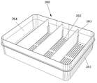
도 2는 본 발명의 일 실시예에 따른 물분사부를 가지는 식물 재배기의 식재부를 도시한 사시도이고,
도 3은 본 발명의 일 실시예에 따른 물분사부를 가지는 식물 재배기의 제 1 식재모듈을 도시한 분해 사시도이고,
도 4는 본 발명의 일 실시예에 따른 물분사부를 가지는 식물 재배기의 제 1 식재모듈을 도시한 사시도이고,
도 5는 본 발명의 일 실시예에 따른 물분사부를 가지는 식물 재배기의 제 2 식재모듈을 도시한 분해 사시도이고,
도 6은 본 발명의 일 실시예에 따른 물분사부를 가지는 식물 재배기의 제 2 식재모듈을 도시한 사시도이고,
도 7은 본 발명의 일 실시예에 따른 물분사부를 가지는 식물 재배기의 제 3 식재모듈을 도시한 사시도이고,
도 8은 본 발명의 일 실시예에 따른 물분사부를 가지는 식물 재배기의 제 3 식재모듈의 장착모습을 도시한 사시도이고
도 9는 본 발명의 일 실시예에 따른 물분사부를 가지는 식물 재배기의 물분사부를 도시한 사시도이고,
도 10은 본 발명의 일 실시예에 따른 물분사부를 가지는 식물 재배기의 물분사부를 확대하여 도시한 사시도이고,
도 11은 본 발명의 일 실시예에 따른 물분사부를 가지는 식물 재배기의 물분사부를 도시한 단면도이다.1 is a perspective view showing a plant grower having a water spray unit according to an embodiment of the present invention,
2 is a perspective view illustrating a planting part of a plant grower having a water spraying part according to an embodiment of the present invention;
3 is an exploded perspective view illustrating a first planting module of a plant grower having a water spraying unit according to an embodiment of the present invention;
Figure 4 is a perspective view showing a first planting module of the plant cultivator having a water spray according to an embodiment of the present invention,
5 is an exploded perspective view illustrating a second planting module of a plant grower having a water spraying unit according to an embodiment of the present invention;
6 is a perspective view illustrating a second planting module of a plant grower having a water spraying unit according to an embodiment of the present invention;
7 is a perspective view showing a third planting module of the plant cultivator having a water spraying unit according to an embodiment of the present invention,
8 is a perspective view showing the mounting appearance of the third planting module of the plant cultivator having a water spray according to an embodiment of the present invention;
9 is a perspective view illustrating a water spray unit of the plant grower having a water spray unit according to an embodiment of the present invention;
10 is an enlarged perspective view illustrating a water spray unit of a plant grower having a water spray unit according to an embodiment of the present invention;
11 is a cross-sectional view illustrating a water spray unit of the plant cultivator having a water spray unit according to an embodiment of the present invention.
본 발명은 다양한 변경을 가할 수 있고, 여러 가지 실시예를 가질 수 있는 바, 특정 실시예들을 도면에 예시하고, 상세하게 설명하고자 한다. 그러나, 이는 본 발명을 특정한 실시 형태에 대해 한정하려는 것이 아니고, 본 발명의 기술 사상 및 기술 범위에 포함되는 모든 변경, 균등물 내지 대체물을 포함하는 식으로 이해 되어야 하고, 여러 가지 다른 형태로 변형될 수 있으며, 본 발명의 범위가 하기 실시예에 한정되는 것은 아니다. While the invention is susceptible to various modifications and alternative forms, specific embodiments thereof are shown by way of example in the drawings and will herein be described in detail. It is to be understood, however, that the invention is not to be limited to the specific embodiments, but is to be understood to cover all modifications, equivalents, and alternatives falling within the spirit and scope of the invention, And the scope of the present invention is not limited to the following examples.
이하, 첨부된 도면을 참조하여 본 발명에 따른 실시예를 상세히 설명하며, 도면 부호에 관계없이 동일하거나 대응하는 구성요소에 대해서는 동일한 참조 번호를 부여하고, 이에 대해 중복되는 설명을 생략하기로 한다.Hereinafter, embodiments of the present invention will be described in detail with reference to the accompanying drawings, wherein like or corresponding elements are denoted by the same reference numerals, and redundant explanations thereof will be omitted.
도 1은 본 발명의 일 실시예에 따른 물분사부를 가지는 식물 재배기를 도시한 사시도이다.1 is a perspective view showing a plant cultivator having a water spray according to an embodiment of the present invention.
도 1을 참조하면, 본 발명의 일 실시예에 따른 물분사부를 가지는 식물 재배기는 본체(100)와, 식재부(200)와, 광원(300)과, 물분사부(400)를 포함할 수 있으며, 물분사부(400)는 본체(100)에 마련되는 물저장부(110)로부터 펌프(미도시)의 펌핑력에 의해 급수라인(미도시)으로부터 공급되는 물을 홀이나 슬릿 형태의 분사구를 통해서 식재부(200)에 식재된 식물을 향하여 분사하도록 한다.Referring to FIG. 1, a plant grower having a water spraying unit according to an embodiment of the present invention may include a
본체(100)는 하부에 물이 저장되기 위한 물저장부(110)가 설치되고, 일례로 물저장부(110)가 용기 형태로 이루어져서 전방으로 슬라이딩 가능하게 착탈되도록 결합되며, 상방으로 한 쌍의 수직부재(120)가 연장되도록 마련되고, 수직부재(120)의 상단에 어퍼부재(130)가 수평되게 마련되며, 일례로 수직부재(120)와 어퍼부재(130)가 억지 끼움 등에 의해 분리 가능하게 결합된다. 한편, 본체(100)는 내측에 설치된 펌프(미도시)의 펌핑력에 의해 급수라인(미도시)을 통해서 물을 식재부(200)와 물분사부(400)에 공급되도록 한다. 여기서, 급수라인(미도시)은 일측이 펌프에 연결되고, 타측이 식재부(200)와 물분사부(400) 각각에 물을 공급하도록 다수로 분기되는 분기관으로 이루어질 수 있다.The
본체(100)는 펌프와 광원(300)의 구동을 온(on)/오프(off)시킴과 아울러, 식재부(200)와 물분사부(400) 각각에 대하여 물의 공급을 개폐시키도록 급수라인에 설치된 밸브를 동작시키기 위한 다수의 스위치로 이루어진 조작패널이 정면에 마련될 수 있다. The
본체(100)는 후술하게 될 물분사부(400)의 분사슬릿(430; 도 9 내지 도 11에 도시)으로부터 분사되는 물에 의한 가습 효과가 상방으로 확산되도록 상부에 마련되는 어퍼부재(130)에 상하로 관통하도록 통풍구(140)가 형성될 수 있으며, 전면과 후면에 개구(150)가 형성될 수 있다.The
도 2 내지 도 8을 참조하면, 식재부(200)는 본체(100)에 마련되어 식물이 식재되기 위한 장소를 제공하는데, 장착부(210)와, 식재모듈(220,240,260)을 포함할 수 있다.2 to 8, the
장착부(210)는 본체(100)에 상방으로 개방되도록 마련되고, 일례로 어퍼부재(130)의 하방에 위치함과 아울러 물저장부(110)의 상방에 위치하도록 형성될 수 있고, 단일 또는 다수의 식재모듈(220,240,260)이 장착되도록 단일로 이루어지거나, 식재모듈(220,240,260) 각각이 장착되도록 다수, 예컨대 한 쌍으로 이루어질 수 있다. 본 실시예에서처럼 장착부(210)는 다양한 형태의 식재모듈(220,240,260) 중에서 선택해서 장착부(210)에 단일 또는 다수로 장착될 수 있다.
식재모듈(220,240,260)은 장착부(210)에 착탈 가능하게 장착되고, 식물의 식재를 위한 식재공간(221,241,264)이 마련된다. 또한 식재모듈(220,240,260) 중에서 일부의 식재모듈(220,240)은 본체(100)에 마련된 물저장부(110)로부터 펌프의 펌핑력에 의해 공급되는 물을 저장하기 위하여 내부에 저장공간(222,242)이 형성될 수 있고, 식재공간(221,241)에 저장공간(222,242)과의 연결을 위한 연결홀(223,243)이 슬릿 형태 또는 원형이나 다각형의 홀을 비롯한 다양한 형태를 가지도록 형성될 수 있다. 연결홀(223,243)은 식재공간(221,241)으로 분사 내지 공급되는 물이 저장공간(222,242)으로 흐르기 위한 통로 역할을 한다.The
식재모듈(220,240,260)은 본 실시예에서처럼 장착부(210)에 수평되게 다수, 예컨대 한 쌍으로 배열되어 각각 장착될 수 있다. 한편, 식재공간(221)은 격벽(232)에 의하여 구획됨으로써 다수로 이루어질 수 있다.The
식재모듈(220,240,260) 중 일부의 식재모듈(220,240)은 서로 마주보는 측에 급배수홈(224,244)이 각각 형성될 수 있고, 급배수홈(224,244)에 저장공간(222,242)으로부터 오버플로우(overflow)되는 물을 배출하기 위한 배수구(225,245)와 물저장부(110)로부터 펌프의 펌핑에 의해 저장공간(242)으로 물이 공급되는 급수라인이 연결되는 연결포트(247) 중 어느 하나 또는 모두가 마련될 수 있으며, 설치 위치로부터 상방으로 이격되기 위한 다수의 레그(228,248)가 마련될 수 있다. 여기서, 레그(228,248)는 장착부(210) 내의 구조물에 지지될 수 있다.Some of the
식재모듈(220,240,260) 각각은 그 설명의 편의를 위하여, 제 1 식재모듈(220), 제 2 식재모듈(240), 그리고 제 3 식재모듈(260)로 구분하여 설명하기로 한다. 즉, 식재모듈(220,240,260)은 새싹식물의 식재를 위한 제 1 식재모듈(220)과, 다양한 식물의 개별적인 재배를 위한 제 2 식재모듈(240)과, 육상 식물 등의 재배를 위한 제 3 식재모듈(260)을 포함할 수 있다. Each of the
도 3 및 도 4를 참조하면, 제 1 식재모듈(220)은 일례로 새싹식물이 식재되기 위한 것으로서, 식재트레이(229)와, 식재받침용기(231)를 포함할 수 있다.Referring to FIGS. 3 and 4, the
식재트레이(229)는 식재공간(221)이 상부에 마련되고, 저면에 연결홀(223)이 형성되며, 가장자리가 식재받침용기(231)에 끼움 등에 의해 결합될 수 있다. The
식재받침용기(231)는 식재트레이(229)의 하측에 결합되어 내부에 물의 저장을 위한 저장공간(222)이 형성되고, 일측에 저장공간(222)의 수위를 일정하게 유지하기 위하여 물저장부(110)로부터 오버플로우되는 물을 배출하기 위한 배수구(225)가 마련될 수 있다.Planting
식재트레이(229) 및 식재받침용기(231)는 일측에 급배수홈(224)이 형성되고, 서로의 결합을 위하여 겹치는 정도가 클 경우 배수구(225)가 식재트레이(229)에도 형성될 수 있으며, 이러한 배수구(225)가 급배수홈(224)에 형성될 수 있다.The
도 5 및 도 6을 참조하면, 제 2 식재모듈(240)은 식물을 개별적으로 재배되기 위한 것으로서, 컵트레이(251)와, 컵받침용기(254)와, 식재컵(256)을 포함할 수 있다.5 and 6, the
컵트레이(251)는 제 1 삽입홀(249)이 다수로 형성되고, 가장자리가 컵받침용기(254)의 가장자리에 끼움 등의 방식에 의해 결합될 수 있다.The
컵받침용기(254)는 컵트레이(251)의 하측에 결합되고, 제 1 삽입홀(249) 각각에 대응하도록 제 2 삽입홀(252)이 형성되며, 내부에 저장공간(242)이 형성되고, 제 2 삽입홀(252)의 내측에 연결홀(243)이 형성되며, 연결홀(243)의 주위에 걸림부(253)가 돌출되도록 형성되고, 저장공간(242)에 대한 수위를 일정하게 유지하기 위하여 오버플로우되는 물을 배출하기 위한 배수구(245)가 마련되며, 물저장부(110)로부터 펌프의 펌핑에 의해 저장공간(242)으로 물이 공급되는 급수라인이 착탈 가능하게 연결되는 연결포트(247)가 마련된다. 한편, 배수구(245)에는 개폐를 위한 마개(246)가 나사 결합 또는 끼움 결합 등에 의해 착탈 가능하게 설치될 수 있다.The
컵트레이(251) 및 컵받침용기(254)는 일측에 급배수홈(244)이 형성되는데, 컵받침용기(254)에서 급배수홈(244)에 배수구(245)와 연결포트(247)가 마련됨으로써, 컵트레이(251)는 이러한 배수구(245)와 연결포트(247)의 유로를 확보하도록 이들과의 간섭을 회피하기 위한 홀 또는 홈이 형성될 수 있다. 즉 컵트레이(251)는 컵받침용기(254)와의 결합을 위해 가장자리 부분이 서로 겹쳐지는 경우 배수구(245)와 연결포트(247) 각각에 대응되는 배수구 및 급수구가 각각 형성될 수 있다.A
식재컵(256)은 제 1 또는 제 2 삽입홀(249,252)에 상응하는 개수로 이루어지고, 제 1 및 제 2 삽입홀(249,252)에 장착되고, 걸림부(253)에 걸림과 아울러 연결홀(243)에 연결되기 위한 걸림홀(255)이 형성되며, 내측에 식재공간(241)이 형성된다. 또한 식재컵(256)은 하방으로 갈수록 폭이나 직경이 감소되도록 형성됨으로써 제 1 및 제 2 삽입홀(249,252)에 하방으로 삽입시 걸림홀(255)에 걸림부(253)가 쉽게 걸리도록 한다.The
식재컵(256)은 상방으로 개방되도록 형성됨으로써 내측의 식재공간(241)에 식물이 식재되고, 제 2 삽입홀(252) 내에 연결홀(243) 및 걸림부(253)가 다수로 형성될 경우 걸림홀(244)이 이러한 연결홀(243) 및 걸림부(253) 각각에 대응하도록 측면에 다수로 형성될 수 있으며, 저면에 배수구(257)가 형성될 수 있다.When the
도 7 및 도 8을 참조하면, 제 3 식재모듈(260)은 식재공간(264)이 내측에 마련되고, 식재공간(264)의 저면에 본체(100)의 물저장부(110)로 물이 배출되기 위한 배수구(262)가 형성되며, 식재공간(264)의 내측에 식재공간(264)을 다수로 분할하기 위한 격판(263)이 수직되게 슬라이딩 가능하도록 결합될 수 있다.7 and 8, in the
도 9를 참조하면, 광원(300)은 본체(100)의 상부, 예컨대 어퍼부재(130)의 저면에 식재부(200)에 식재된 식물에 광을 조사하도록 다수로 설치될 수 있고, 일례로 LED가 다수로 배열로 배열되는 LED 어레이로 이루어질 수 있으며, 외부로부터 공급되는 전원에 의해 광을 발산하되, 본체(100)의 전면에 마련된 조작패널에 의해 온(on)/오프(off)된다. Referring to FIG. 9, the
도 9 내지 도 11을 참조하면, 물분사부(400)는 물의 분사를 위하여, 일례로 홀 형태를 가진 분사구가 마련될 수 있고, 다른 예로서 본 실시예에서처럼 분사슬릿(430)과 같이 슬릿 형태의 분사구가 마련될 수 있다. 여기서, 홀 형태의 분사구는 단일 또는 다수로 이루어질 수 있고, 반드시 원형만을 의미하는 것이 아니라, 삼각형이나 사각형 등의 다각형이나 타원형을 비롯하여 다양한 도형의 홀을 포함할 수 있다. 또한, 슬릿 형태의 분사구는 단일 또는 다수로 이루어질 수 있고, 슬릿 형태라면 그 형상에는 제한이 없다.9 to 11, the
물분사부(400)는 본 실시예에서처럼, 본체(100)의 상부, 예컨대 어퍼부재(130)의 저면에 식재부(200)에 식재된 식물에 물을 분사하도록 설치되고, 본 실시예에서처럼 본체(100)의 상부에 하방을 향하도록 마련되는 몸체(410)와, 몸체(410)에 마련되고, 본체(100)에 마련된 물저장부(110)로부터 펌프의 펌핑력에 의해 물이 공급되는 급수라인에 연결되는 급수포트(420)와, 급수포트(420)를 통해서 공급되는 물이 몸체(410)의 중심부로부터 가장자리 방향으로 확산되어 분사되도록 몸체(410)의 둘레에 마련되는 분사슬릿(430)을 포함할 수 있다. 또한, 물분사부(400)는 광원들(300)의 사이에 각각 설치되도록 다수로 이루어질 수 있다.The
몸체(410)는 본 실시예에서처럼 평단면이 원형으로 이루어지고, 하단에 마련되는 원반(411)과의 사이에 분사슬릿(430)이 형성될 수 있다. 원반(411)은 상면에 형성되는 끼움돌기(412)에 의해 몸체(410)에 끼워짐으로써 고정될 수 있다.The
급수포트(420)는 분사슬릿(430)의 일측으로부터 측방향으로 연장되도록 돌출 형성됨으로써 급수라인이 착탈 가능하게 끼움 방식 등에 의해 연결되고, 끝단에 급수라인의 이탈을 제한하도록 외주면을 따라 돌기가 형성될 수 있다. The
분사슬릿(430)은 몸체(410)의 중심부로부터 가장자리측으로 하향 경사지게 형성될 수 있다. 이를 위해 원반(411)은 상부가 원추 형상으로 이루어질 수 있다.The spray slit 430 may be formed to be inclined downward from the center of the
이와 같은 본 발명에 따른 물분사부를 가지는 식물 재배기의 작용을 설명하기로 한다.This will be described the operation of the plant grower having a water spray according to the present invention.
식재부(200)의 장착부(210)에 식재하고자 하는 식물의 종류나 식재환경에 따라 적절한 식재모듈(220,240,260)을 선택하여 장착한다. 이때, 식재모듈(220,240,260)에는 미리 원하는 식물을 식재할 수 있다. The
식재모듈(220,240,260)에 대한 식물의 식재와 장착을 마치고, 식재된 식물의 식재 과정에서 본체(100)에 마련된 조작패널의 조작에 의하여, 광원(300)과 펌프를 구동시킴으로써 식물에 적절한 광과 수분을 공급하도록 한다. After planting and mounting plants for the
LED 어레이로 이루어진 광원(300)에 의해 식물에 균일하게 광을 공급하도록 하여 실내에서도 식물의 식생이 제대로 이루어지도록 하고, 물분사부(400), 특히 분사슬릿(430)을 통해서 분사되는 물이 식물에 균일하게 스프레이되도록 하여 식물에 골고루 수분을 공급하고, 나아가서, 식재모듈(220,240,260)에 분사되는 물이 본체(100)의 물저장부(110)로 회수되어 펌프의 펌핑에 의해 재공급될 수 있도록 한다.By uniformly supplying light to the plant by the
이와 같이 첨부된 도면을 참조하여 본 발명을 설명하였으나, 본 발명의 기술적 사상을 벗어나지 않는 범위 내에서 다양한 수정 및 변형이 이루어질 수 있음은 물론이다. 그러므로, 본 발명의 범위는 설명된 실시예에 국한되어 정해져서는 안되며, 후술하는 특허청구범위뿐만 아니라 이러한 특허청구범위와 균등한 것들에 의해 정해져야 한다.Although the present invention has been described with reference to the accompanying drawings, it is to be understood that various changes and modifications may be made without departing from the spirit of the invention. Therefore, the scope of the present invention should not be limited to the described embodiments, but should be determined by the equivalents of the claims, as well as the following claims.
100 : 본체 110 : 물저장부
120 : 수직부재 130 : 어퍼부재
140 : 통풍구 200 : 식재부
210 : 장착부 220 : 제 1 식재모듈
221 : 식재공간 222 : 저장공간
223 : 연결홀 224 : 급배수홈
225 : 배수구 228 : 레그
229 : 식재트레이 231 : 식재받침용기
232 : 격벽 240 : 제 2 식재모듈
241 : 식재공간 242 : 저장공간
243 : 연결홀 244 : 급배수홈
245 : 배수구 246 : 마개
247 : 연결포트 248 : 레그
249 : 제 1 삽입홀 251 : 컵트레이
252 : 제 2 삽입홀 253 : 걸림부
254 : 컵받침용기 255 : 걸림홀
256 : 식재컵 257 : 배수구
260 : 제 3 식재모듈 261 : 식재용기
262 : 배수구 263 : 격판
264 : 식재공간 300 : 광원
400 : 물분사부 410 : 몸체
411 : 원반 420 : 급수포트
430 : 분사슬릿100: main body 110: water storage
120: vertical member 130: upper member
140: vent 200: planting department
210: mounting part 220: first planting module
221: planting space 222: storage space
223: Connection hole 224: Water supply drain groove
225: Drain 228: Leg
229: food material tray 231: food material container
232: partition wall 240: second food module
241: Planting space 242: Storage space
243: Connection hole 244: Water supply drain groove
245: drain hole 246: stopper
247: connection port 248: leg
249: first insertion hole 251: cup tray
252: second insertion hole 253:
254: Coasters container 255: Jam hole
256: planting cup 257: drain
260: Third planting module 261: Planting container
262: Drain 263: Diaphragm
264: Planting space 300: Light source
400: water splashing part 410: body
411: disc 420: water supply port
430: injection slit
Claims (6)
본체에 식물이 식재되기 위한 식재부가 마련되고, 상기 식재부에 식재된 식물에 광을 조사하도록 상기 본체에 광원이 설치되며, 상기 식재부에 식재된 식물에 물을 분사하도록 상기 본체에 물분사부가 설치되고,
상기 물분사부는,
상기 본체에 마련되는 물저장부로부터 펌프의 펌핑력에 의해 급수라인으로부터 공급되는 물을 홀이나 슬릿 형태의 분사구를 통해서 식재부에 식재된 식물을 향하여 분사하는 것을 특징으로 하는 물분사부를 가지는 식물 재배기.In plant cultivation,
A planting part is provided in the main body for planting, the light source is installed in the main body to irradiate light on the plant planted in the planting part, and the water spraying unit in the main body so as to spray water on the plant planted in the planting part. Installed,
The water spray unit,
Plant cultivator having a water spraying unit characterized in that for spraying the water supplied from the water supply line by the pumping force of the pump from the water storage unit provided in the main body toward the plant planted in the planting part through a hole or a slit-shaped injection port .
상기 본체의 상부에 하방을 향하도록 마련되는 몸체;
상기 몸체에 마련되고, 상기 급수라인에 연결되는 급수포트; 및
상기 급수포트를 통해서 공급되는 물이 상기 몸체의 중심부로부터 가장자리 방향으로 확산되어 분사되도록 상기 몸체의 둘레에 마련되는 분사슬릿을 포함하는 것을 특징으로 하는 물분사부를 가지는 식물 재배기.According to claim 1, wherein the water spray unit,
A body provided downward on an upper portion of the main body;
A water supply port provided on the body and connected to the water supply line; And
And a spraying slit provided around the body so that water supplied through the water supply port is sprayed by being spread from the center of the body to the edge.
상기 본체에 상부에 마련되는 어퍼부재의 저면에 다수로 설치되고, LED가 다수로 배열되는 LED 어레이로 이루어지며,
상기 물분사부는,
상기 광원들의 사이에 각각 설치되도록 다수로 이루어지는 것을 특징으로 하는 물분사부를 가지는 식물 재배기.The method of claim 1, wherein the light source,
Is installed in a plurality of the lower surface of the upper member is provided on the main body, the LED array is made of a plurality of,
The water spray unit,
Plant cultivator having a water spray, characterized in that consisting of a plurality so as to be installed between each of the light sources.
하단에 마련되는 원반과의 사이에 상기 분사슬릿이 형성되는 것을 특징으로 하는 물분사부를 가지는 식물 재배기.[3] The apparatus of claim 2,
Plant cultivator having a water spray unit, characterized in that the injection slit is formed between the disk provided at the bottom.
상기 몸체의 중심부로부터 가장자리측으로 하향 경사지게 형성되는 것을 특징으로 하는 물분사부를 가지는 식물 재배기.The method of claim 2 or 4, wherein the injection slit,
Plant cultivator having a water spray portion characterized in that the inclined downward from the center of the body toward the edge.
상기 물분사부로부터 분사되는 물에 의한 가습 효과가 상방으로 확산되도록 상부에 마련되는 어퍼부재에 상하로 관통하도록 통풍구가 형성되는 것을 특징으로 하는 물분사부를 가지는 식물 재배기.The main body according to any one of claims 1 to 4, wherein
And a vent hole is formed to penetrate upward and downward through an upper member provided at an upper portion so that a humidifying effect of water sprayed from the water spraying unit is spread upward.
Priority Applications (1)
| Application Number | Priority Date | Filing Date | Title |
|---|---|---|---|
| KR1020120051319A KR101379738B1 (en) | 2012-05-15 | 2012-05-15 | Plant cultivation apparatus having water diffusion supply unit |
Applications Claiming Priority (1)
| Application Number | Priority Date | Filing Date | Title |
|---|---|---|---|
| KR1020120051319A KR101379738B1 (en) | 2012-05-15 | 2012-05-15 | Plant cultivation apparatus having water diffusion supply unit |
Publications (2)
| Publication Number | Publication Date |
|---|---|
| KR20130127646A true KR20130127646A (en) | 2013-11-25 |
| KR101379738B1 KR101379738B1 (en) | 2014-03-31 |
Family
ID=49855066
Family Applications (1)
| Application Number | Title | Priority Date | Filing Date |
|---|---|---|---|
| KR1020120051319A KR101379738B1 (en) | 2012-05-15 | 2012-05-15 | Plant cultivation apparatus having water diffusion supply unit |
Country Status (1)
| Country | Link |
|---|---|
| KR (1) | KR101379738B1 (en) |
Cited By (2)
| Publication number | Priority date | Publication date | Assignee | Title |
|---|---|---|---|---|
| CN106550807A (en) * | 2016-11-16 | 2017-04-05 | 刘德平 | A kind of colored room Humidity regulating equipment based on technology of Internet of things |
| EP3726962A4 (en) * | 2017-12-22 | 2021-12-08 | Aspara Limited | An apparatus, a system, a method and a light control device for facilitating hydroponic cultivation |
Family Cites Families (3)
| Publication number | Priority date | Publication date | Assignee | Title |
|---|---|---|---|---|
| KR101102733B1 (en) * | 2009-10-30 | 2012-01-05 | 황용수 | Vegetable cultivating equipment for home use |
| KR101004333B1 (en) * | 2010-07-06 | 2010-12-28 | 마소영 | Multi-cultivating apparatus |
| KR101231624B1 (en) * | 2010-09-08 | 2013-02-15 | 주식회사 두두비전 | agreculture apparatus |
-
2012
- 2012-05-15 KR KR1020120051319A patent/KR101379738B1/en not_active IP Right Cessation
Cited By (2)
| Publication number | Priority date | Publication date | Assignee | Title |
|---|---|---|---|---|
| CN106550807A (en) * | 2016-11-16 | 2017-04-05 | 刘德平 | A kind of colored room Humidity regulating equipment based on technology of Internet of things |
| EP3726962A4 (en) * | 2017-12-22 | 2021-12-08 | Aspara Limited | An apparatus, a system, a method and a light control device for facilitating hydroponic cultivation |
Also Published As
| Publication number | Publication date |
|---|---|
| KR101379738B1 (en) | 2014-03-31 |
Similar Documents
| Publication | Publication Date | Title |
|---|---|---|
| US10701870B2 (en) | Multifunctional hanging-type plant-growing assembly | |
| US9357715B2 (en) | Vertical planter | |
| KR101371128B1 (en) | Exchangeble plant cultivation apparatus having cultivation module | |
| KR101127310B1 (en) | Rotatable multistage flower pot | |
| FI125733B (en) | VERTICAL PLANTING PLANT FOR CULTIVATING PLANTS | |
| KR101893196B1 (en) | Plant cultivation device | |
| KR20140122821A (en) | Hydroponic culturing device | |
| KR200476709Y1 (en) | Water culture apparatus | |
| KR20120128526A (en) | Hanger type multilayer apparatus with column structure for hydroponic cultivating | |
| KR101334603B1 (en) | Plant cultivation apparatus having darkroom maintain cover | |
| KR20130131867A (en) | Cultivating plant apparatus using culture solution | |
| KR101004333B1 (en) | Multi-cultivating apparatus | |
| KR101466179B1 (en) | Hydroponics apparatus with aquarium | |
| KR20190137201A (en) | Election type garden system | |
| CN111937626B (en) | Potted plant maintenance device | |
| KR20120133903A (en) | Device for multi hydroponics | |
| KR101158002B1 (en) | Multipurpose plant cultivation device | |
| KR20130111845A (en) | Multifunctional household device for cultivating vegetable and sprout | |
| KR101379738B1 (en) | Plant cultivation apparatus having water diffusion supply unit | |
| KR20150103390A (en) | A watering flowerpot which the power is useless | |
| KR20140137654A (en) | Modular Plant Cultivation Device | |
| KR200309893Y1 (en) | water culture | |
| KR20120111872A (en) | Device to cultivate of plant | |
| KR200405862Y1 (en) | Device for hydroponics | |
| KR102506677B1 (en) | Plant cultivating apparatus |
Legal Events
| Date | Code | Title | Description |
|---|---|---|---|
| A201 | Request for examination | ||
| E902 | Notification of reason for refusal | ||
| E701 | Decision to grant or registration of patent right | ||
| FPAY | Annual fee payment | ||
| GRNT | Written decision to grant | ||
| LAPS | Lapse due to unpaid annual fee |