KR20130124731A - Tidal current power plant device using the barge - Google Patents
Tidal current power plant device using the barge Download PDFInfo
- Publication number
- KR20130124731A KR20130124731A KR1020120048074A KR20120048074A KR20130124731A KR 20130124731 A KR20130124731 A KR 20130124731A KR 1020120048074 A KR1020120048074 A KR 1020120048074A KR 20120048074 A KR20120048074 A KR 20120048074A KR 20130124731 A KR20130124731 A KR 20130124731A
- Authority
- KR
- South Korea
- Prior art keywords
- barge
- chain belt
- rotating
- algae
- tidal current
- Prior art date
Links
Images


Classifications
-
- F—MECHANICAL ENGINEERING; LIGHTING; HEATING; WEAPONS; BLASTING
- F03—MACHINES OR ENGINES FOR LIQUIDS; WIND, SPRING, OR WEIGHT MOTORS; PRODUCING MECHANICAL POWER OR A REACTIVE PROPULSIVE THRUST, NOT OTHERWISE PROVIDED FOR
- F03B—MACHINES OR ENGINES FOR LIQUIDS
- F03B13/00—Adaptations of machines or engines for special use; Combinations of machines or engines with driving or driven apparatus; Power stations or aggregates
- F03B13/12—Adaptations of machines or engines for special use; Combinations of machines or engines with driving or driven apparatus; Power stations or aggregates characterised by using wave or tide energy
- F03B13/26—Adaptations of machines or engines for special use; Combinations of machines or engines with driving or driven apparatus; Power stations or aggregates characterised by using wave or tide energy using tide energy
- F03B13/264—Adaptations of machines or engines for special use; Combinations of machines or engines with driving or driven apparatus; Power stations or aggregates characterised by using wave or tide energy using tide energy using the horizontal flow of water resulting from tide movement
-
- F—MECHANICAL ENGINEERING; LIGHTING; HEATING; WEAPONS; BLASTING
- F03—MACHINES OR ENGINES FOR LIQUIDS; WIND, SPRING, OR WEIGHT MOTORS; PRODUCING MECHANICAL POWER OR A REACTIVE PROPULSIVE THRUST, NOT OTHERWISE PROVIDED FOR
- F03B—MACHINES OR ENGINES FOR LIQUIDS
- F03B13/00—Adaptations of machines or engines for special use; Combinations of machines or engines with driving or driven apparatus; Power stations or aggregates
- F03B13/10—Submerged units incorporating electric generators or motors
-
- F—MECHANICAL ENGINEERING; LIGHTING; HEATING; WEAPONS; BLASTING
- F03—MACHINES OR ENGINES FOR LIQUIDS; WIND, SPRING, OR WEIGHT MOTORS; PRODUCING MECHANICAL POWER OR A REACTIVE PROPULSIVE THRUST, NOT OTHERWISE PROVIDED FOR
- F03B—MACHINES OR ENGINES FOR LIQUIDS
- F03B7/00—Water wheels
- F03B7/006—Water wheels of the endless-chain type
-
- B—PERFORMING OPERATIONS; TRANSPORTING
- B63—SHIPS OR OTHER WATERBORNE VESSELS; RELATED EQUIPMENT
- B63B—SHIPS OR OTHER WATERBORNE VESSELS; EQUIPMENT FOR SHIPPING
- B63B35/00—Vessels or similar floating structures specially adapted for specific purposes and not otherwise provided for
- B63B35/28—Barges or lighters
-
- F—MECHANICAL ENGINEERING; LIGHTING; HEATING; WEAPONS; BLASTING
- F05—INDEXING SCHEMES RELATING TO ENGINES OR PUMPS IN VARIOUS SUBCLASSES OF CLASSES F01-F04
- F05B—INDEXING SCHEME RELATING TO WIND, SPRING, WEIGHT, INERTIA OR LIKE MOTORS, TO MACHINES OR ENGINES FOR LIQUIDS COVERED BY SUBCLASSES F03B, F03D AND F03G
- F05B2220/00—Application
- F05B2220/30—Application in turbines
- F05B2220/32—Application in turbines in water turbines
-
- F—MECHANICAL ENGINEERING; LIGHTING; HEATING; WEAPONS; BLASTING
- F05—INDEXING SCHEMES RELATING TO ENGINES OR PUMPS IN VARIOUS SUBCLASSES OF CLASSES F01-F04
- F05B—INDEXING SCHEME RELATING TO WIND, SPRING, WEIGHT, INERTIA OR LIKE MOTORS, TO MACHINES OR ENGINES FOR LIQUIDS COVERED BY SUBCLASSES F03B, F03D AND F03G
- F05B2220/00—Application
- F05B2220/70—Application in combination with
- F05B2220/706—Application in combination with an electrical generator
-
- Y—GENERAL TAGGING OF NEW TECHNOLOGICAL DEVELOPMENTS; GENERAL TAGGING OF CROSS-SECTIONAL TECHNOLOGIES SPANNING OVER SEVERAL SECTIONS OF THE IPC; TECHNICAL SUBJECTS COVERED BY FORMER USPC CROSS-REFERENCE ART COLLECTIONS [XRACs] AND DIGESTS
- Y02—TECHNOLOGIES OR APPLICATIONS FOR MITIGATION OR ADAPTATION AGAINST CLIMATE CHANGE
- Y02E—REDUCTION OF GREENHOUSE GAS [GHG] EMISSIONS, RELATED TO ENERGY GENERATION, TRANSMISSION OR DISTRIBUTION
- Y02E10/00—Energy generation through renewable energy sources
- Y02E10/20—Hydro energy
-
- Y—GENERAL TAGGING OF NEW TECHNOLOGICAL DEVELOPMENTS; GENERAL TAGGING OF CROSS-SECTIONAL TECHNOLOGIES SPANNING OVER SEVERAL SECTIONS OF THE IPC; TECHNICAL SUBJECTS COVERED BY FORMER USPC CROSS-REFERENCE ART COLLECTIONS [XRACs] AND DIGESTS
- Y02—TECHNOLOGIES OR APPLICATIONS FOR MITIGATION OR ADAPTATION AGAINST CLIMATE CHANGE
- Y02E—REDUCTION OF GREENHOUSE GAS [GHG] EMISSIONS, RELATED TO ENERGY GENERATION, TRANSMISSION OR DISTRIBUTION
- Y02E10/00—Energy generation through renewable energy sources
- Y02E10/30—Energy from the sea, e.g. using wave energy or salinity gradient
Abstract
Description
본 발명은 바지선을 이용한 조류 발전 장치에 관한 것으로서, 특히 바지선 하부에 구비된 체인벨트가 조류에 의해 회전할 수 있게 하여 조류발전이 가능하게 하기 위한 것이며, 또한 조류와 같은 자연에너지를 통해 조류발전이 가능하게 함으로써 해양오염이나 수생태계의 환경오염을 예방하여 환경보전이 가능하게 하기 위한 바지선을 이용한 조류 발전 장치에 관한 것이다.
The present invention relates to an algae power generation apparatus using a barge, and in particular, to enable the algae power generation by allowing the chain belt provided under the barge to rotate by the algae, algae power generation through natural energy such as algae The present invention relates to an algae power generation apparatus using a barge to prevent environmental pollution of marine or aquatic ecosystems by making it possible.
일반적으로 조류발전은 조류가 빠르게 흐르는 해저에 프로펠러가 장착된 수차발전기를 설치한 뒤 조류의 힘에 의해 수차발전기를 회전시켜 전력을 생산하는 것으로, 특히 조류발전은 기후변화나 계절에 관계없이 발전이 항시 가능하고 신재생에너지 중 유일하게 발전 가능량을 예측할 수 있는 에너지원이라 할 수 있다.Generally, algae power is generated by installing a water turbine with propeller on the seabed where the algae flows rapidly, and then rotating the water generator by the force of the algae to produce electric power regardless of climate change or season. It is an energy source that is always available and is the only renewable energy that can predict the amount of power available.
이처럼, 조류발전장치는 해수의 흐름이 빠른 곳에 수차발전기를 설치해 해수의 운동에너지를 이용하여 발전하는 장치로서, 종래의 조류발전장치는 대부분 해저에 기둥을 매설하고, 상부에 발전기를 설치하여 해수의 흐름에 의해 발전하도록 하고 있다.As such, the tidal current generator is a device that generates water using kinetic energy of the seawater by installing a water turbine generator in a place where the flow of seawater is fast. Most conventional tidal current generators embed pillars in the seabed and install a generator on the top of the seawater. It is being developed by the flow.
즉, 발전기의 일측에 구비되는 프로펠러가 해수의 흐름에 의하여 회전하면서 발전하도록 구비된 것이다.In other words, the propeller provided on one side of the generator is provided to generate power while rotating by the flow of sea water.
그러나 종래의 조류발전장치는 상술한 구조물을 설치하기 위해서 해저바닥에 기초구조물을 설치하거나 지상에서 제작된 대형의 기초구조물을 해저바닥에 투하하여 구성하는 형식을 취할 수밖에 없어 작업의 난이성은 물론 해양오염으로 인한 해양환경 생태계에 악영향을 미칠 수 있는 우려가 높았던 문제가 있었다.
However, in order to install the above-described structure, the conventional algae generator has to take the form of installing the foundation structure on the bottom of the sea floor or by dropping the large foundation structure manufactured on the ground on the bottom of the sea. There was a high concern that could adversely affect the marine environment ecosystem.
본 발명은 상기의 문제점을 해소하기 위한 바지선을 이용한 조류 발전 장치에 관한 것으로서, 특히 바지선 하부에 구비된 체인벨트가 조류에 의해 회전할 수 있게 하여 조류발전이 가능하게 하기 위한 것이며, 또한 조류와 같은 자연에너지를 통해 조류발전이 가능하게 함으로써 해양오염이나 수생태계의 환경오염을 예방하여 환경보전이 가능하게 하기 위한 것을 목적으로 한다.
The present invention relates to an algae power generation apparatus using a barge to solve the above problems, in particular to enable the chain belt provided in the lower barge to rotate by the algae to enable algae power generation, and also such as algae It aims to enable environmental preservation by preventing algae generation through natural energy and preventing environmental pollution of marine or aquatic ecosystems.
이러한 본 발명은 해수면에 띄워지는 바지선과; 상기 바지선 저면 하부에 구비되는 지지부재와; 상기 지지부재의 전방과 후방에 구비되는 회전스프로킷과; 상기 회전스프로킷과 결합하여 회전하는 체인벨트와; 상기 체인벨트 외측면에 일방향으로 회동 가능하게 구비되며, 조류에 의해 회동하여 상기 체인벨트를 회전시키는 복수 개의 조류가압패널과; 상기 회전스프로킷과 연결되어 상기 체인벨트의 회전동력을 상기 바지선에 구비되는 발전기로 전달하는 구동스프로킷;을 포함함으로써 달성된다.This invention is a barge floating on the sea surface; A support member provided below the barge bottom surface; Rotating sprockets provided at the front and rear of the support member; A chain belt rotating in combination with the rotary sprocket; A plurality of algae pressurizing panels provided on the outer side of the chain belt so as to be rotatable in one direction and rotating by the algae to rotate the chain belt; It is achieved by including a; drive sprocket connected to the rotary sprocket for transmitting the rotational power of the chain belt to the generator provided on the barge.
이때, 상기 지지부재의 전방 및 후방에 장착되어 조류의 흐름을 유도하는 조류유도패널이 추가로 구비되도록 하는 것이 바람직하다.At this time, it is preferable to further be provided with an algae induction panel mounted on the front and rear of the support member to induce the flow of algae.
또한, 전방에 구비된 상기 조류유도패널은 전방 상측을 향해 비스듬하게 형성되며, 후방에 구비된 상기 조류유도패널은 후방 하측을 향해 비스듬하게 형성되도록 하는 것이 바람직하다.In addition, the algae induction panel provided in the front is formed obliquely toward the front upper side, it is preferable that the algae induction panel provided in the rear is formed obliquely toward the rear lower side.
이때, 상기 조류가압패널은; 상기 체인벨트에 장착되는 회동부재와, 상기 회동부재에 장착되는 패널부재로 이루어지도록 하는 것이 바람직하다.At this time, the algae pressure panel; Preferably, the rotating member is mounted to the chain belt and the panel member is mounted to the rotating member.
한편, 상기 체인벨트는 한 쌍으로 이루어지며, 상기 회전스프로킷은 전방과 후방에 각각 한 쌍씩 구비되어 상기 체인벨트가 상기 회전스프로킷에 각각 맞물려 일체로 회전 가능하게 구비되도록 하는 것이 바람직하다.On the other hand, the chain belt is made of a pair, it is preferable that the rotary sprocket is provided in pairs respectively at the front and the rear so that the chain belt is engaged with the rotary sprocket respectively to be rotatably provided integrally.
한편, 상기 조류가압패널은 상기 체인벨트에 각각 장착되는 한 쌍의 회동부재와, 상기 한 쌍의 회동부재에 장착되는 패널부재로 이루어지도록 하는 것이 바람직하다.On the other hand, the tidal pressure panel is preferably made of a pair of rotating members mounted to the chain belt, respectively, and a panel member mounted to the pair of rotating members.
이때, 상기 회동부재는 수평부와 수직부로 이루어지되; 상기 수직부의 양측면 하단에는 연장부가 형성되고, 상기 연장부는 상기 체인벨트의 외측으로 연장 돌출된 체인핀에 회동 가능하게 장착되도록 하는 것이 바람직하다.At this time, the rotating member is made of a horizontal portion and a vertical portion; Extension parts are formed at both lower ends of the vertical part, and the extension parts may be rotatably mounted to the chain pins protruding outwardly of the chain belt.
또한, 상기 패널부재의 상부에는 상기 회동부재가 스탠딩되기 시작할 때 조류의 힘을 용이하게 받을 수 있도록 가압판이 추가로 형성되도록 하는 것이 바람직하다.In addition, it is preferable that the pressing plate is further formed on the upper portion of the panel member so as to easily receive the force of the algae when the rotating member starts to stand.
한편, 상기 지지부재의 상부와 하부에는 상기 체인벨트를 지지하는 다수의 처짐방지부재가 수평방향으로 구비되도록 하는 것이 바람직하다.On the other hand, the upper and lower portions of the support member is preferably provided with a plurality of deflection preventing member for supporting the chain belt in the horizontal direction.
한편, 상기 지지부재가 상기 바지선 저면 하부에 경사지게 위치하도록 하는 것이 바람직하다.
On the other hand, it is preferable that the support member is positioned to be inclined under the barge bottom.
이상과 같은 본 발명은 비교적 간단한 시설만으로도 조류발전이 가능하게 하여 발전설비 설치비용과 발전설비 운영비가 절약되게 함으로써 단위 전력 당 생산비용이 저렴하게 되어 경제적인 면에서 실용성을 증대시킬 수 있으며, 또한 조류가 있는 바다 어느 곳에서나 설치가 가능하고 자연에너지를 활용함으로 인해 친환경적인 효율 좋은 발전 장치를 완성함으로써 상품성을 향상시키는데 효과가 있는 발명인 것이다.
As described above, the present invention enables tidal power generation even with a relatively simple facility, thereby reducing power generation installation cost and power generation operation cost, thereby lowering the production cost per unit power, thereby increasing the practicality in terms of economics. It is an invention that can be installed anywhere in the sea and is effective to improve the commerciality by completing an eco-friendly and efficient power generation device by utilizing natural energy.
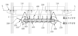
도 1은 본 발명의 바지선을 이용한 조류 발전 장치를 도시하는 측면도,
도 2는 본 발명의 바지선을 이용한 조류 발전 장치를 도시하는 평면도,
도 3은 본 발명의 바지선을 이용한 조류 발전 장치에서 조류유도패널을 도시하는 도면,
도 4의 (a)는 본 발명의 바지선을 이용한 조류 발전 장치에서 체인벨트에 회동 가능하게 체결된 조류가압패널의 회동부재를 도시하는 도면,
도 4의 (b)는 도 4의 (a)에서 체인벨트와 회동부재의 체결 상태를 도시하는 단면도,
도 4의 (c)는 본 발명의 바지선을 이용한 조류 발전 장치에서 체인벨트에 회동 가능하게 체결된 조류가압패널의 회동부재의 다른 실시예를 도시하는 단면도,
도 5는 본 발명의 바지선을 이용한 조류 발전 장치에서 조류가압패널을 도시하는 도면,
도 6은 본 발명의 바지선을 이용한 조류 발전 장치에서 지지부재, 체인벨트, 조류가압패널, 구동스프로킷 및 처짐방지부재를 도시하는 평면도,
도 7의 (a)는 본 발명의 바지선을 이용한 조류 발전 장치에서 회전스프로킷, 체인벨트, 조류가압패널, 구동스프로킷 및 연결체인의 결합관계를 도시하는 도면,
도 7의 (b)는 본 발명의 바지선을 이용한 조류 발전 장치에서 회전스프로킷, 체인벨트, 조류가압패널의 결합관계를 도시하는 단면도,
도 8은 본 발명의 바지선을 이용한 조류 발전 장치의 다른 실시예를 도시하는 측면도.1 is a side view showing a tidal current generating device using a barge of the present invention,
2 is a plan view showing a tidal current generating device using a barge of the present invention,
3 is a view showing a bird induction panel in the algae power generation apparatus using a barge of the present invention,
Figure 4 (a) is a view showing a rotating member of the bird pressure panel rotatably fastened to the chain belt in the tidal current generator using the barge of the present invention,
Figure 4 (b) is a cross-sectional view showing a fastening state of the chain belt and the rotating member in Figure 4 (a),
Figure 4 (c) is a cross-sectional view showing another embodiment of the rotating member of the tide pressure panel rotatably fastened to the chain belt in the tidal current generator using the barge of the present invention,
5 is a view showing a bird pressure panel in the algae power generation apparatus using a barge of the present invention,
Figure 6 is a plan view showing a support member, a chain belt, a bird pressure panel, a drive sprocket and a deflection prevention member in the tidal current generator using the barge of the present invention,
Figure 7 (a) is a view showing a coupling relationship between the rotary sprocket, the chain belt, the bird pressure panel, the drive sprocket and the connecting chain in the tidal current generator using the barge of the present invention,
Figure 7 (b) is a cross-sectional view showing a coupling relationship between the rotating sprocket, the chain belt, the bird pressure panel in the algae power generation apparatus using the barge of the present invention,
8 is a side view showing another embodiment of the tidal current generating device using the barge of the present invention.
도 1 내지 도 8은 본 발명의 바지선을 이용한 조류 발전 장치에 관한 것으로, 도 1은 본 발명의 바지선을 이용한 조류 발전 장치를 도시하는 측면도이며, 도 2는 본 발명의 바지선을 이용한 조류 발전 장치를 도시하는 평면도이다.1 to 8 relates to an algae power generation apparatus using a barge of the present invention, Figure 1 is a side view showing an algae power generation apparatus using a barge of the present invention, Figure 2 is a tidal power generation device using a barge of the present invention It is a top view which shows.
또한, 도 3은 본 발명의 바지선을 이용한 조류 발전 장치에서 조류유도패널을 도시하는 도면이며, 도 4는 본 발명의 바지선을 이용한 조류 발전 장치에서 체인벨트와 조류가압패널의 회동부재의 체결 상태를 도시하는 도면이고, 도 5는 본 발명의 바지선을 이용한 조류 발전 장치에서 조류가압패널을 도시하는 도면이다.In addition, Figure 3 is a view showing a bird induction panel in the algae power generating apparatus using the barge of the present invention, Figure 4 is a fastening state of the rotating member of the chain belt and the bird pressure panel in the algae power generating apparatus using the barge of the present invention. 5 is a view showing a tidal pressure panel in the tidal current generator using the barge of the present invention.
또한, 도 6은 본 발명의 바지선을 이용한 조류 발전 장치에서 지지부재, 체인벨트, 조류가압패널, 구동스프로킷 및 처짐방지부재를 도시하는 평면도이며, 도 7은 본 발명의 바지선을 이용한 조류 발전 장치에서 회전스프로킷, 체인벨트, 조류가압패널 및 구동스프로킷의 결합관계를 도시하는 도면이다.6 is a plan view showing a support member, a chain belt, a bird pressure panel, a driving sprocket and a deflection prevention member in the tidal current generator using the barge of the present invention, Figure 7 is a tidal current generator using the barge of the present invention Figure is a diagram showing the coupling relationship between the rotary sprocket, the chain belt, the tidal pressure panel and the drive sprocket.
또한, 도 8은 본 발명의 바지선을 이용한 조류 발전 장치의 다른 실시예를 도시하는 측면도이다.
8 is a side view showing another embodiment of the tidal current generating device using the barge of the present invention.
본 발명의 실시예를 첨부 도면을 참조하여 상세히 설명하면 다음과 같다.DETAILED DESCRIPTION OF THE PREFERRED EMBODIMENTS Hereinafter, embodiments of the present invention will be described in detail with reference to the accompanying drawings.
본 발명의 바지선을 이용한 조류 발전 장치는 도 1 내지 도 8에 도시된 바와 같이, 발전기(110)를 포함하는 바지선(100)과, 상기 바지선(100) 하부에 구비되는 지지부재(200)와, 상기 지지부재(200) 전후방에 구비되는 회전스프로킷(310)과, 상기 회전스프로킷(310)과 연결되어 회전 가능하게 구비되는 체인벨트(300)와, 상기 체인벨트(300) 외측면에 구비되는 조류가압패널(400)과, 상기 체인벨트(300)의 회전동력을 상기 발전기(110)로 전달하는 구동스프로킷(500)으로 이루어져 조류발전이 가능하게 하여 실용성을 증대시키는 동시에 자연에너지를 활용함으로 인해 상품성을 향상시키게 되는 것을 그 기술상의 기본 특징으로 한다.
1 to 8, the algae power generation apparatus using the barge of the present invention, the
이하 본 발명의 바지선을 이용한 조류 발전 장치에 대한 각 구성요소를 첨부한 도면을 참조하여 하나씩 살펴보면 다음과 같다.Hereinafter, each component of the tidal current generating device using the barge of the present invention will be described with reference to the accompanying drawings, one by one.
우선 본 발명은 도 1 및 도 2에 도시된 바와 같이 바지선(100)과, 상기 바지선(100) 하부에 구비되는 지지부재(200)와, 상기 지지부재(200) 전후방에 위치하는 회전스프로킷(310)과, 상기 회전스프로킷(310)을 따라 회전하는 체인벨트(300)와, 상기 체인벨트(300) 외측면에 구비되어 조류의 유동을 통해 상기 체인벨트(300)를 회전시키는 조류가압패널(400)과, 상기 체인벨트(300)의 회전동력을 바지선(100)의 발전기(110)로 전달하는 구동스프로킷(500)으로 이루어지는 것을 기본으로 한다.First, as shown in FIGS. 1 and 2, the
바지선(100)은 항만 내부나 하구 등 비교적 짧은 거리에서 화물을 수송하는 거룻배로서 부두에서 본선까지 화물을 나르거나 반대로 본선에서 부두까지 화물을 실어 나르는 역할을 하는데 통상적으로 해수면에 띄워진 상태로 구비된다. The
또한, 바지선(100)은 측면에 고정강관(P)이 다수 구비되는데 상기 고정강관(P)은 그 하부가 해수면 지하에 수직방향으로 견고하게 고정되어 상기 바지선(100)이 전후좌우 방향으로 임의로 이동하게 되는 것을 제한하는 동시에 밀물과 썰물 시에는 상하방향으로 이동할 수 있도록 하며, 여기서 상기 바지선(100)은 연결끈(L)을 통해서도 육지 등에 고정시킬 수 있게 한다.In addition, the
이때, 바지선(100) 하부에 구비되는 지지부재(200)는 해수면으로부터 일정 높이 아래에서 조류의 흐름이 가장 강한 지점에 위치하도록 설치한다.At this time, the
한편, 본 발명의 바지선(100)은 조류를 이용하여 발생된 동력을 에너지로 변환시킬 수 있는 발전기(110)를 포함하도록 한다.On the other hand, the
지지부재(200)는 바지선(100) 저면 하부에 일정 간격을 두고 고정되게 구비되는 것으로, 이하 기술하게 될 체인벨트(300)와 연동되어 상기 체인벨트(300)가 조류에 의해 회전할 수 있게 지지하는 동시에 회전하면서 발생되는 회전동력이 바지선(100)의 발전기(110)로 전달되는 것이 가능하게 한다.The
또한, 도 1 내지 도 3에 도시된 바와 같이 지지부재(200) 전방과 후방에는 조류유도패널(210)이 구비되어 조류의 흐름을 상기 지지부재(200) 상면 또는 하면을 향해 효율적으로 전달할 수 있게 하는 것이 바람직하다.In addition, as shown in Figures 1 to 3, the
이를 위해 지지부재(200) 전방에 구비된 조류유도패널(210)은 전방 상측을 향해 비스듬하게 형성되어 조류의 방향이 전방에서 발생되면 조류가 지지부재(200) 하면을 타고 지나갈 수 있게 유도하며, 지지부재(200) 후방에 구비된 조류유도패널(210)은 후방 하측을 향해 비스듬하게 형성되어 조류의 방향이 후방에서 발생되면 조류가 지지부재(200) 상면을 타고 지나갈 수 있게 유도한다.To this end, the bird-guided
이때, 지지부재(200)는 사다리 형상으로 구비되며, 상기 지지부재(200)에 길이 방향으로 체인벨트(300)가 구비되도록 한다.At this time, the
도 1, 2 및 7에 도시된 바와 같이, 체인벨트(300)는 지지부재(200)의 전방과 후방에 구비된 회전스프로킷(310, 도 7 참조) 외주면에 구비되며, 상기 체인벨트(300)가 전후방의 회전스프로킷(310)과 연결됨으로 인해 맞물려 회전할 수 있게 한다.1, 2 and 7, the
여기서, 체인벨트(300)의 회전방향은 후방에서 전방, 또는 전방에서 후방으로 회전하는 것이 가능하지만 설명의 명확성을 위해서 본 발명에서는 도 1에 도시된 조류의 흐름에 따라 후방에서 전방으로 회전하는 것을 기준으로 설명한다.Here, the rotation direction of the
한편, 바람직하게는 체인벨트(300)가 한 쌍으로 이루어져 평행하게 구비되며, 회전스프로킷(310)은 지지부재(200)의 전방에 한 쌍, 후방에 한 쌍씩 구비되어 상기 체인벨트(300)가 회전스프로킷(310)의 외주면에 맞물려 구동샤프트(S1, 도 2 및 도 7 참조)를 통해 일체로 회전할 수 있게 하는 것이 좋다.On the other hand, the
한편, 체인벨트(300)는 상술한 바와 같이 체인으로 이루어지는 것을 기본으로 하지만 벨트 컨베이어가 적용될 수도 있다.On the other hand, the
도 1 및 도 2에 도시된 바와 같이, 조류가압패널(400)은 체인벨트(300) 외측면(도면상 체인벨트(300)의 상부 또는 하부)에 일방향으로 회동 가능하게 구비되어 조류의 방향에 따라 선택적으로 회동하여 상기 체인벨트(300)를 회전시킨다.1 and 2, the
상기 조류가압패널(400)은 체인벨트(300) 외측면에 복수 개 구비되어 조류의 방향이 후방에서 전방을 향하게 되면 지지부재(200)를 기준으로 체인벨트(300) 상면에 위치하게 되는 조류가압패널(400)은 상방을 향해 스탠딩(standing) 되어 조류의 흐름을 전달 받게 됨으로 인해 상기 체인벨트(300)가 후방에서 전방으로 회전할 수 있게 되며, 이때 지지부재(200)를 기준으로 체인벨트(300) 하면에 위치하게 되는 조류가압패널(400)은 후방에서 전방으로 향하는 조류에 의해 쓰러지게 되어 상기 체인벨트(300) 외측 하면에 위치하게 된다.The
한편, 조류의 방향이 전방에서 후방을 향하게 되면 지지부재(200)를 기준으로 체인벨트(300) 상면에 위치하는 조류가압패널(400)이 쓰러지게 되며, 지지부재(200)를 기준으로 체인벨트(300) 하면에 위치하는 조류가압패널(400)이 스탠딩 되어 상기 체인벨트(300)가 회전하게 된다. 즉, 조류의 방향이 전방에서 후방, 후방에서 전방으로 흐르더라도 체인벨트(300)의 회전이 모두 가능하며 조류발전이 가능하게 한다.On the other hand, when the direction of the bird from the front to the rear, the bird
이때, 조류가압패널(400)은 회동부재(410)와, 상기 회동부재(410)에 장착되는 패널부재(420)로 이루어지며, 상기 회동부재(410)는 다시 수평부(411)와, 수직부(412)와, 연장부(413)로 이루어진다.At this time, the
여기서, 상기 연장부(413)는 도 4의 (a) 및 (b)에 도시된 바와 같이, 회동부재(410)의 수직부(412) 양측면 하방으로 연장부(413)가 형성되도록 하여, 상기 연장부(413)가 체인벨트(300) 외측에서 체결되도록 한다.Here, as shown in FIGS. 4A and 4B, the
한편, 조류가압패널(400)은 도 5에 도시된 바와 같이, 한 쌍의 회동부재(410)와, 상기 한 쌍의 회동부재(410)에 장착되는 패널부재(420)로 이루어지도록 하는 것이 바람직하다.On the other hand, as shown in Figure 5, the
이때, 연장부(413)는 '∩'자 형상으로 이루어져 체인벨트(300) 외측에 위치하며, 상기 체인벨트(300)의 외측으로 연장 돌출된 체인핀(S2)과 상호 회동 가능하게 결합된다.At this time, the
그 결과, 회동부재(410)를 포함하는 조류가압패널(400)이 체인벨트(300)로부터 간섭 없이 회동할 수 있게 된다.As a result, the tidal-pressure
이때, 도 4의 (c)에 도시된 바와 같이, 수직부(412) 하단에 별도의 연장부(413, 도 4의 (b) 참조)를 형성하는 대신 체인벨트(300)의 외측으로 연장 돌출된 체인핀(S2)과 체결되는 브래킷(B)이 구비되도록 하여 상기 브래킷(B)과 수직부(412)를 회동핀(S3)을 통해 연결시켜 상기 회동부재(410)를 포함하는 조류가압패널(400)이 상기 체인벨트(300)로부터 회동하는 것이 가능하게 할 수도 있다.At this time, as shown in (c) of Figure 4, instead of forming a separate extension portion 413 (see Fig. 4 (b)) at the bottom of the
또한, 도 5에 도시된 바와 같이 패널부재(420)는 상기 회동부재(410)에 장착되어 조류 발생 시 조류의 힘을 받을 수 있게 한다. 이때 패널부재(420)의 일측면 상부에는 가압판(421, 도 5 참조)이 경사지게 형성되어 상기 회동부재(410)가 스탠딩을 시작할 때부터 스탠딩이 완료될 때 까지 조류의 힘을 보다 용이하게 받을 수 있게 하는 것이 바람직하다.In addition, as shown in FIG. 5, the
여기서, 조류가압패널(400)의 회동부재(410)는 회동이 가능하도록 L자 형상으로 이루어지도록 하되, 예를 들어 도 1에 도시된 바와 같이 조류가 후방에서 전방으로 이동할 때는 지지부재(200)를 기준으로 체인벨트(300) 상면에 위치하는 상기 회동부재(410)의 수평부(411, 도 4 참조)가 전방을 향해 위치하게 되며, 이때 상기 수평부(411)가 걸림수단의 역할을 하여 체인벨트(300)에 의해 지지되어 스탠딩하게 된다. 반대로 조류가 전방에서 후방으로 이동하게 되면 상기 회동부재(410)에서 걸림수단의 역할을 하는 부위가 없기 때문에 상기 회동부재(410)가 쓰러지게 된다.Here, the rotating
한편, 도 1 및 도 2에 도시된 바와 같이 지지부재(200)의 상부와 하부에는 체인벨트(300)를 지지하는 다수의 처짐방지부재(220)가 수평방향으로 구비되도록 하여 체인 또는 벨트 형상의 상기 체인벨트(300)가 처지게 되는 현상을 미연에 방지하도록 하는 것이 바람직하다.Meanwhile, as illustrated in FIGS. 1 and 2, the upper and lower portions of the
이때, 처짐방지부재(220)는 플레이트 또는 롤러 등이 이용될 수 있게 하여 체인벨트(300)의 처짐 현상 방지 및 이동 능력을 향상시킬 수 있게 하는 것이 좋다.At this time, the
도 1 및 도 2에 도시된 바와 같이 구동스프로킷(500)은 체인벨트(300)에 형성된 회전스프로킷(310)과 연결되어 조류를 이용하여 조류가압패널(400)에 의해 회전하는 상기 체인벨트(300)의 회전동력을 바지선(100)의 발전기(110)로 전달한다.As shown in FIG. 1 and FIG. 2, the driving
이때, 구동스프로킷(500)의 외주면은 추가로 구비되는 연결체인(C)을 통해 발전기(110)와 상호 맞물려 연결되도록 하는 것이 바람직하다.In this case, the outer circumferential surface of the driving
여기서, 상기 연결체인(C)은 폐곡선 형상으로 이루어져, 일단은 구동스프로킷(500) 외주면에 맞물리며, 타단은 발전기(110) 측의 스프로킷과 연결되어 체인벨트(300)의 회전동력을 상기 발전기(110)로 전달하는 것이 가능하게 한다.Here, the connection chain (C) is made of a closed curve shape, one end is engaged to the outer peripheral surface of the
한편, 도 1 및 도 2에 도시된 바와 같이 구동스프로킷(500)은 전방에 한 쌍, 후방에 한 쌍씩 구비되며 상기 구동스프로킷(500)과 연결되는 연결체인(C) 또한 전후방에 각각 한 쌍씩 구비되어, 체인벨트(300)와 연결된 회전스프로킷(310)이 전후방에 한 쌍씩 구비되는 경우 상호 대응하여 연결될 수 있게 하는 것이 바람직하다.Meanwhile, as shown in FIGS. 1 and 2, the driving
또한, 체인벨트(300) 중간에 회전스프로킷(310)과 구동스프로킷(500)을 추가로 설치하며, 바지선에도 발전기(110)를 추가로 설치하여 회전동력을 전달력과 그로 인한 조류 발전이 가능하게 한다.In addition, the
이때, 구동스프로킷(500)과 발전기(110)의 연결은 연결체인(C)뿐만 아니라 벨트(미도시)와 같이 다른 방법을 통해서도 연결시킬 수 있게 하는 것이 바람직하다.At this time, it is preferable that the connection between the driving
또한, 회전스프로킷(310)과 구동스프로킷(500)은 구동샤프트(S1)를 통해 결합되어 회전력 전달이 가능하게 하는 것이 바람직하다.In addition, the
한편, 도 8은 본 발명의 다른 실시예로 지지부재(200)가 바지선(100) 하부에 경사지게 위치하도록 함으로써 조류가압패널(400)이 조류의 압력을 보다 효과적으로 받을 수 있게 하여 조류발전을 용이하게 할 수도 있다.
On the other hand, Figure 8 is another embodiment of the present invention by positioning the
이하, 본 발명의 작용 및 효과를 설명하면 다음과 같다.Hereinafter, functions and effects of the present invention will be described.
도 1 및 도 2에 도시된 바와 같이, 본 발명은 발전기(110)를 포함하는 바지선(100)과, 상기 바지선(100) 저면 하부에 구비되는 지지부재(200)와, 상기 지지부재(200) 전후방에 구비되는 회전스프로킷(310)과, 상기 회전스프로킷(310)을 따라 회전 가능하게 구비되는 체인벨트(300)와, 상기 체인벨트(300) 외측면에 구비되는 조류가압패널(400)과, 상기 체인벨트(300)의 회전동력을 상기 발전기(110)로 전달하는 구동스프로킷(500)으로 이루어져 조류발전이 가능하게 하여 실용성을 증대시키는 동시에 자연에너지를 활용함으로 인해 상품성을 향상시킬 수 있게 한다.1 and 2, the present invention provides a
이때, 도 1 및 도 4에 도시된 바와 같이 지지부재(200) 전방과 후방에 구비된 조류유도패널(210)을 통해 조류의 흐름을 상기 지지부재(200) 상면 또는 지지부재(200) 하면으로 전달할 수 있게 하여 조류가압패널(400)에 조류의 흐름 전달력을 높일 수 있게 한다.At this time, as shown in Figures 1 and 4 through the
그 결과, 조류가압패널(400)에 조류의 흐름이 전달되면 조류방향에 따라 상기 조류가압패널(400)이 스탠딩 되거나 쓰러지게 되는데, 조류의 방향이 후방에서 전방을 향하게 되면 지지부재(200)를 기준으로 상기 체인벨트(300) 상면에 위치하는 조류가압패널(400)은 스탠딩(standing) 되어 조류의 흐름을 전달 받게 되기 때문에 상기 체인벨트(300)가 후방에서 전방으로 회전할 수 있게 되며, 이때 지지부재(200)를 기준으로 체인벨트(300) 하면에 위치하는 조류가압패널(400)은 후방에서 전방으로 향하는 조류에 의해 쓰러지게 되어 조류의 흐름을 막지 않고 그대로 흘러 보내게 된다.As a result, when the flow of algae is transmitted to the
또한, 조류의 방향이 전방에서 후방을 향하게 되면 지지부재(200)를 기준으로 체인벨트(300) 상면에 위치하는 조류가압패널(400)이 쓰러지게 되어 조류의 흐름을 흘러 보내게 되며, 지지부재(200)를 기준으로 상기 체인벨트(300) 하면에 위치하는 조류가압패널(400)은 스탠딩 되어 조류의 흐름을 전달 받게 되기 때문에 상기 체인벨트(300)가 회전하게 된다.In addition, when the direction of the tidal flow from the front to the rear, the
이처럼, 해수면 아래에서 발생되는 조류를 이용하여 체인벨트(300)를 회전시키게 되면 회전동력이 발생하게 되는데 이때 상기 체인벨트(300)의 회전스프로킷(310)과 구동스프로킷(500)을 구동샤프트(S1, 도 6 및 도 7 참조)를 통해 연결시키며, 상기 구동스프로킷(500)을 다시 바지선(100)의 발전기(110)와 연결체인(C)을 통해 연결시키고, 상기 체인벨트(300)에서 발생된 회전동력을 상기 구동스프로킷(500)을 거쳐 상기 발전기(110)로 전달함으로써 조류발전이 가능하게 한다.
As such, when the
상기와 같이 구성된 본 발명의 바지선을 이용한 조류 발전 장치는 해수면에 띄워지는 바지선과; 상기 바지선 저면 하부에 구비되는 지지부재와; 상기 지지부재의 전방과 후방에 구비되는 회전스프로킷과; 상기 회전스프로킷과 결합하여 회전하는 체인벨트와; 상기 체인벨트 외측면에 일방향으로 회동 가능하게 구비되며, 조류에 의해 회동하여 상기 체인벨트를 회전시키는 복수 개의 조류가압패널과; 상기 회전스프로킷과 연결되어 상기 체인벨트의 회전동력을 상기 바지선에 구비되는 발전기로 전달하는 구동스프로킷으로 구성되어 비교적 간단한 시설만으로도 조류발전이 가능하게 하여 발전설비 설치비용과 발전설비 운영비가 절약되게 함으로써 단위전력 당 생산비용이 저렴하게 되어 경제적인 면에서 실용성을 증대시킬 수 있으며, 또한 조류가 있는 바다 어느 곳에서나 설치가 가능하고 자연에너지를 활용함으로 인해 친환경적인 효율 좋은 발전 장치를 완성함으로써 상품성을 향상시키는데 탁월한 이점을 가진 발명인 것이다.
Algae generating apparatus using the barge of the present invention configured as described above and the barge floating on the sea surface; A support member provided below the barge bottom surface; Rotating sprockets provided at the front and rear of the support member; A chain belt rotating in combination with the rotary sprocket; A plurality of algae pressurizing panels provided on the outer side of the chain belt so as to be rotatable in one direction and rotating by the algae to rotate the chain belt; It is connected to the rotating sprocket and consists of a driving sprocket which transmits the rotational power of the chain belt to the generator provided in the barge, so that tidal power generation is possible even with a relatively simple facility, thereby saving power generation installation cost and power generation operation cost. The production cost per power can be lowered to increase the practicality in terms of economics, and can be installed anywhere in the sea where there is tide, and by using natural energy, it is possible to improve the merchandise by completing eco-friendly and efficient power generation equipment. It is an invention with excellent advantages.
이상과 같이, 본 발명은 비록 한정된 실시예와 도면에 의해 설명되었으나, 본 발명은 이것에 의해 한정되지 않으며 본 발명이 속하는 기술분야에서 통상의 지식을 가진 자에 의해 본 발명의 기술사상과 아래에 기재될 특허청구범위 내에서 다양한 수정 및 변형이 가능함은 물론이다.
While the present invention has been particularly shown and described with reference to exemplary embodiments thereof, it is to be understood that the invention is not limited to the disclosed exemplary embodiments. It is to be understood that various changes and modifications may be made without departing from the scope of the appended claims.
100 : 바지선 110 : 발전기
200 : 지지부재 210 : 조류유도패널
220 : 처짐방지부재 300 : 체인벨트
400 : 조류가압패널 410 : 회동부재
420 : 패널부재 500 : 구동스프로킷
C : 연결체인 S1 : 구동샤프트
S2 : 체인핀 S3 : 회동핀
B : 브래킷 L : 연결끈100: barge 110: generator
200: support member 210: bird guide panel
220: deflection prevention member 300: chain belt
400: bird pressure panel 410: rotating member
420: panel member 500: drive sprocket
C: Connecting Chain S1: Drive Shaft
S2: Chain Pin S3: Rotating Pin
B: Bracket L: String
Claims (10)
상기 바지선 저면 하부에 구비되는 지지부재와;
상기 지지부재의 전방과 후방에 구비되는 회전스프로킷과;
상기 회전스프로킷과 결합하여 회전하는 체인벨트와;
상기 체인벨트 외측면에 일방향으로 회동 가능하게 구비되며, 조류에 의해 회동하여 상기 체인벨트를 회전시키는 복수 개의 조류가압패널과;
상기 회전스프로킷과 연결되어 상기 체인벨트의 회전동력을 상기 바지선에 구비되는 발전기로 전달하는 구동스프로킷;을 포함하는 것을 특징으로 하는 바지선을 이용한 조류 발전 장치.
Barges floated at sea level;
A support member provided below the barge bottom surface;
Rotating sprockets provided at the front and rear of the support member;
A chain belt rotating in combination with the rotary sprocket;
A plurality of algae pressurizing panels provided on the outer side of the chain belt so as to be rotatable in one direction and rotating by the algae to rotate the chain belt;
And a driving sprocket connected to the rotating sprocket for transmitting the rotational power of the chain belt to the generator provided in the barge.
상기 지지부재의 전방 및 후방에 장착되어 조류의 흐름을 유도하는 조류유도패널이 추가로 구비되는 것을 특징으로 하는 바지선을 이용한 조류 발전 장치.
The method according to claim 1,
The algae generating apparatus using a barge, characterized in that the algae induction panel is mounted to the front and rear of the support member to further induce the flow of algae.
전방에 구비된 상기 조류유도패널은 전방 상측을 향해 비스듬하게 형성되며, 후방에 구비된 상기 조류유도패널은 후방 하측을 향해 비스듬하게 형성되는 것을 특징으로 하는 바지선을 이용한 조류 발전 장치.
The method according to claim 2,
The algae induction panel provided in the front is formed obliquely toward the front upper side, and the algae induction panel provided in the rear is formed obliquely toward the rear lower side.
상기 조류가압패널은;
상기 체인벨트에 장착되는 회동부재와, 상기 회동부재에 장착되는 패널부재로 이루어지는 것을 특징으로 하는 바지선을 이용한 조류 발전 장치.
The method according to claim 1,
The algae pressure panel is;
Tidal power generation apparatus using a barge, characterized in that consisting of a rotating member mounted to the chain belt and a panel member mounted to the rotating member.
상기 체인벨트는 한 쌍으로 이루어지며, 상기 회전스프로킷은 전방과 후방에 각각 한 쌍씩 구비되어 상기 체인벨트가 상기 회전스프로킷에 각각 맞물려 일체로 회전 가능하게 구비되는 것을 특징으로 하는 바지선을 이용한 조류 발전 장치.
The method according to claim 1,
The chain belt is composed of a pair, and the rotary sprocket is provided in pairs respectively in the front and the rear so that the chain belt is engaged with the rotary sprocket, respectively, the tidal current generating device using a barge, characterized in that the rotatably provided. .
상기 조류가압패널은;
상기 체인벨트에 각각 장착되는 한 쌍의 회동부재와, 상기 한 쌍의 회동부재에 장착되는 패널부재로 이루어지는 것을 특징으로 하는 바지선을 이용한 조류 발전 장치.
The method according to claim 5,
The algae pressure panel is;
A tidal current generating device using a barge, characterized in that consisting of a pair of rotating members mounted to the chain belt, respectively, and a panel member mounted to the pair of rotating members.
상기 회동부재는 수평부와 수직부로 이루어지되; 상기 수직부의 양측면 하단에는 연장부가 형성되고, 상기 연장부는 상기 체인벨트의 외측으로 연장 돌출된 체인핀에 회동 가능하게 장착되는 것을 특징으로 하는 바지선을 이용한 조류 발전 장치.
The method according to claim 4 or 6,
The rotating member is composed of a horizontal portion and a vertical portion; Extension portions are formed at both lower ends of the vertical portion, and the extension portion is rotatably mounted on a chain pin protruding outwardly of the chain belt.
상기 패널부재의 상부에는 상기 회동부재가 스탠딩되기 시작할 때 조류의 힘을 용이하게 받을 수 있도록 가압판이 추가로 형성되는 것을 특징으로 하는 바지선을 이용한 조류 발전 장치.
The method according to claim 4 or 6,
The top of the panel member is a tidal current generating device using a barge, characterized in that the pressing plate is further formed to easily receive the force of the tidal current when the rotating member starts to stand.
상기 지지부재의 상부와 하부에는 상기 체인벨트를 지지하는 다수의 처짐방지부재가 수평방향으로 구비되는 것을 특징으로 하는 바지선을 이용한 조류 발전 장치.
The method according to claim 1,
A tidal current generating device using a barge, characterized in that the upper and lower portions of the support member are provided with a plurality of sagging prevention members for supporting the chain belt in a horizontal direction.
상기 지지부재가 상기 바지선 저면 하부에 경사지게 위치하게 되는 것을 특징으로 하는 바지선을 이용한 조류 발전 장치.The method according to claim 1,
The tidal current generation device using a barge, characterized in that the support member is positioned inclined to the bottom of the barge bottom.
Priority Applications (1)
| Application Number | Priority Date | Filing Date | Title |
|---|---|---|---|
| KR1020120048074A KR20130124731A (en) | 2012-05-07 | 2012-05-07 | Tidal current power plant device using the barge |
Applications Claiming Priority (1)
| Application Number | Priority Date | Filing Date | Title |
|---|---|---|---|
| KR1020120048074A KR20130124731A (en) | 2012-05-07 | 2012-05-07 | Tidal current power plant device using the barge |
Publications (1)
| Publication Number | Publication Date |
|---|---|
| KR20130124731A true KR20130124731A (en) | 2013-11-15 |
Family
ID=49853418
Family Applications (1)
| Application Number | Title | Priority Date | Filing Date |
|---|---|---|---|
| KR1020120048074A KR20130124731A (en) | 2012-05-07 | 2012-05-07 | Tidal current power plant device using the barge |
Country Status (1)
| Country | Link |
|---|---|
| KR (1) | KR20130124731A (en) |
Cited By (2)
| Publication number | Priority date | Publication date | Assignee | Title |
|---|---|---|---|---|
| WO2018151452A1 (en) * | 2017-02-20 | 2018-08-23 | 최옥선 | Hydroelectric power generation apparatus using folding flaps |
| US10837421B2 (en) | 2017-07-13 | 2020-11-17 | Yong Soo Cho | Tidal current power generator |
-
2012
- 2012-05-07 KR KR1020120048074A patent/KR20130124731A/en not_active Application Discontinuation
Cited By (3)
| Publication number | Priority date | Publication date | Assignee | Title |
|---|---|---|---|---|
| WO2018151452A1 (en) * | 2017-02-20 | 2018-08-23 | 최옥선 | Hydroelectric power generation apparatus using folding flaps |
| CN110249125A (en) * | 2017-02-20 | 2019-09-17 | 崔沃先 | Utilize the hydroelectric installation of collapsible turnover panel |
| US10837421B2 (en) | 2017-07-13 | 2020-11-17 | Yong Soo Cho | Tidal current power generator |
Similar Documents
| Publication | Publication Date | Title |
|---|---|---|
| CA2685163C (en) | Device for wave-powered generator | |
| CN103629040B (en) | Multi-buoy pendulous wave energy collecting device | |
| US20070018458A1 (en) | Method and apparatus for wave energy conversion using a floating pulley and counterweight | |
| KR101093063B1 (en) | Floating offshore combind generator | |
| WO2010022165A1 (en) | Ocean wave power generator | |
| US7033111B2 (en) | Hydraulic power generating system | |
| KR101138377B1 (en) | Wind and Water power generator ship | |
| AU2016357633B2 (en) | An apparatus for power generation from the surface ocean waves in deep seas | |
| CN102535393B (en) | Floating breakwater provided with wave power generating device and capable of being detached and installed fast | |
| KR101684314B1 (en) | Tidal current generation apparatus | |
| KR101030036B1 (en) | Wave-power generation | |
| CN101555861A (en) | Power generation platform capable of intercepting ocean kinetic energy | |
| KR20150033956A (en) | marine structure equipped with electric generation system using natural energy | |
| KR20130124731A (en) | Tidal current power plant device using the barge | |
| WO2010125552A2 (en) | A water powered electrical generator | |
| WO2007086750A1 (en) | Device for wave-powered generator | |
| CN2858991Y (en) | High power maintenance-free power generator assembly driven by tide and wave | |
| CN102644542A (en) | Tidal power generation equipment | |
| CN104018980A (en) | Pile type wave energy capturing device utilizing plurality of floating bodies | |
| KR20140054942A (en) | Floating offshore wind power generation plant | |
| KR20100117467A (en) | Wave power generating apparatus | |
| CN104405566A (en) | Direct-driven wave energy device using gravity pendulum | |
| CN104405564A (en) | Direct-driven wave energy device using gravity pendulum | |
| KR101400968B1 (en) | Electric generation device using sea energy | |
| CN203890983U (en) | Wave generating set combined with floating type bulwark and port trestle |
Legal Events
| Date | Code | Title | Description |
|---|---|---|---|
| A201 | Request for examination | ||
| E902 | Notification of reason for refusal | ||
| E601 | Decision to refuse application |