KR20130122061A - Drain trap - Google Patents
Drain trap Download PDFInfo
- Publication number
- KR20130122061A KR20130122061A KR1020120045090A KR20120045090A KR20130122061A KR 20130122061 A KR20130122061 A KR 20130122061A KR 1020120045090 A KR1020120045090 A KR 1020120045090A KR 20120045090 A KR20120045090 A KR 20120045090A KR 20130122061 A KR20130122061 A KR 20130122061A
- Authority
- KR
- South Korea
- Prior art keywords
- drain
- groove
- cover
- lifting shaft
- bolt
- Prior art date
Links
Images


Classifications
-
- E—FIXED CONSTRUCTIONS
- E03—WATER SUPPLY; SEWERAGE
- E03F—SEWERS; CESSPOOLS
- E03F5/00—Sewerage structures
- E03F5/04—Gullies inlets, road sinks, floor drains with or without odour seals or sediment traps
- E03F5/0407—Floor drains for indoor use
-
- E—FIXED CONSTRUCTIONS
- E03—WATER SUPPLY; SEWERAGE
- E03F—SEWERS; CESSPOOLS
- E03F5/00—Sewerage structures
- E03F5/04—Gullies inlets, road sinks, floor drains with or without odour seals or sediment traps
- E03F5/041—Accessories therefor
-
- F—MECHANICAL ENGINEERING; LIGHTING; HEATING; WEAPONS; BLASTING
- F16—ENGINEERING ELEMENTS AND UNITS; GENERAL MEASURES FOR PRODUCING AND MAINTAINING EFFECTIVE FUNCTIONING OF MACHINES OR INSTALLATIONS; THERMAL INSULATION IN GENERAL
- F16K—VALVES; TAPS; COCKS; ACTUATING-FLOATS; DEVICES FOR VENTING OR AERATING
- F16K15/00—Check valves
- F16K15/02—Check valves with guided rigid valve members
- F16K15/06—Check valves with guided rigid valve members with guided stems
- F16K15/063—Check valves with guided rigid valve members with guided stems the valve being loaded by a spring
-
- E—FIXED CONSTRUCTIONS
- E03—WATER SUPPLY; SEWERAGE
- E03F—SEWERS; CESSPOOLS
- E03F5/00—Sewerage structures
- E03F5/04—Gullies inlets, road sinks, floor drains with or without odour seals or sediment traps
- E03F2005/0416—Gullies inlets, road sinks, floor drains with or without odour seals or sediment traps with an odour seal
- E03F2005/0417—Gullies inlets, road sinks, floor drains with or without odour seals or sediment traps with an odour seal in the form of a valve
-
- Y—GENERAL TAGGING OF NEW TECHNOLOGICAL DEVELOPMENTS; GENERAL TAGGING OF CROSS-SECTIONAL TECHNOLOGIES SPANNING OVER SEVERAL SECTIONS OF THE IPC; TECHNICAL SUBJECTS COVERED BY FORMER USPC CROSS-REFERENCE ART COLLECTIONS [XRACs] AND DIGESTS
- Y10—TECHNICAL SUBJECTS COVERED BY FORMER USPC
- Y10S—TECHNICAL SUBJECTS COVERED BY FORMER USPC CROSS-REFERENCE ART COLLECTIONS [XRACs] AND DIGESTS
- Y10S4/00—Baths, closets, sinks, and spittoons
- Y10S4/07—House plumbing fittings
Abstract
Description
본 발명은 하수공에 매설되어 오수를 배출하기 위한 배수트랩에 관한 것으로, 더욱 상세하게는 제약, 화공약품 공장 등에서 청소 후 발생하는 오수를 배수관으로 신속하게 배출하고, 역류하는 하수의 악취를 보다 효과적으로 차단할 수 있도록 한 배수트랩에 관한 것이다.The present invention relates to a drain trap for discharging sewage, which is buried in sewage holes, and more particularly, to quickly discharge sewage generated after cleaning in pharmaceuticals, chemicals, factories, etc. It relates to a drain trap that can be blocked.
일반적으로 배수트랩이란 욕실, 다용도실 등의 바닥면에 하수관과 함께 매설되도록 설치되어 각종 생활오수가 배수관으로 배출되도록 함과 동시에 배수관으로부터 역류되는 악취를 차단하는 역할을 한다. 또한, 배수트랩의 상부에는 다수의 배수공이 천공된 덮개가 마련되어 있어 생활오수에 포함된 머리카락 등과 같은 각종 이물질을 걸러준다.In general, the drain trap is installed to be buried together with a sewer pipe on the floor of a bathroom, a utility room, etc., and discharges various kinds of household wastewater into the drain pipe and blocks the odor flowing back from the drain pipe. In addition, the upper part of the drain trap is provided with a cover perforated a plurality of drain holes to filter out various foreign matters, such as hair contained in household sewage.
또한 제약, 화공약품 공장 등에서 청소 후 발생하는 오수는 머리카락 등과 같은 각종 이물질이 거의 포함되어 있지 않기 때문에 배수트랩의 상부에 다수의 배수공이 천공된 덮개를 구비하지 않고, 배수관으로부터 역류되는 악취를 차단하기 위해 배수트랩의 상부에 별도로 밀폐를 위한 덮개를 나사결합하여 사용하고 있으나, 이는 청소를 할 때 일일이 나사결합된 덮개를 풀어서 오수를 배수처리해야 하므로 번거로움이 발생하게 되고, 배수트랩을 장기간 사용하지 않았을 때 덮개의 나사 풀기 및 조임에 상당히 어려움이 발생한다는 문제점이 있었다.In addition, since the sewage generated after cleaning in pharmaceuticals, chemical plants, etc. contains almost no foreign matter such as hair, etc., it is not provided with a cover in which a plurality of drain holes are perforated in the upper part of the drain trap, to prevent odor flowing back from the drain pipe. To cover the top of the drain trap for sealing separately, it is used by screwing, but when cleaning, it is necessary to unscrew the cover and drain the sewage. There was a problem that considerably difficult to unscrew and tighten the cover when not.
상기한 청소 후 발생하는 오수를 배수관으로 신속하게 배출하고, 배수관으로부터 역류되는 악취를 차단하기 위하여 종래에도 다양한 발명이 개발되어 사용되고 있으며, 그 일 예로 대한민국 등록특허공보 제10-0619180호(2006.08.25)의 배수트랩이 개시되어 있다.In order to quickly discharge the sewage generated after the cleaning to the drain pipe, and to block the odor flowing back from the drain pipe, various inventions have been developed and used in the past, for example, Republic of Korea Patent Publication No. 10-0619180 (2006.08.25 Drain trap is disclosed.
상기 대한민국 등록특허공보 제10-0619180호(2006.08.25)의 배수트랩에 대한 기술은 도 10 및 도 11에 도시된 바와 같이, 배수관과 연결되는 본체(200), 상기 본체(200)의 상부에 설치되며 다수 개의 배수공이 천공된 덮개(400) 및 상기 본체(200)의 내부에 설치되는 트랩을 포함하여 구성되는 배수트랩에서, 상기 트랩은 외부하우징(610) 및 상기 외부하우징(610)의 내부에 일체로 고정되는 내부하우징(620)으로 구성되고, 상기 외부하우징(610)은 상부는 개방되고 하부는 밑면(612)으로 막혀 있는 컵 형상으로서, 측면을 따라 배수통로를 제공하는 다수 개의 절개부(614)가 형성되어 있으며, 밑면(612)의 중심부가 상향 돌출되어 밑면(612)의 단면이 방사상으로 대칭되는 2개의 곡선을 이루고 있으며, 상기 내부하우징(620)은 상부 및 하부가 모두 개방된 튜브 형상으로서 상기 외부하우징(610)에 장착되어 일체로 고정된 상태에서 그 하단부가 상기 외부하우징(610)의 측면에 형성된 절개부(614)보다 하부에 위치하는 것을 특징으로 하고 있다.The description of the drain trap of the Republic of Korea Patent Publication No. 10-0619180 (August 25, 2006) is shown in Figure 10 and 11, the
또한, 상기 내부하우징(620)은 상기 외부하우징(610)에 삽입되어 일체로 고정되는 상부관(622) 및 상기 상부관(622)과 연결되어 배수통로를 제공하는 하부관(624)으로 구성되고 상기 하부관(624)과 상기 상부관(622)은 동심원을 형성하고 있다.In addition, the
상기한 구성으로 된 종래의 배수트랩은 덮개(400)의 배수공을 통과한 오수를 한 곳으로 집중시켜 봉수를 밀어내는 힘을 최대화하고, 외부하우징(610)의 밑면(612)의 단면을 방사상으로 곡선이 이루어지도록 하여 오수의 유속을 최대화하여 단위 시간당 배출속도를 최대화할 수 있고, 본체(200), 및 일체로 결합된 내부하우징(620) 및 외부하우징(610)을 분해 및 조립할 수 있도록 구성하여 유지보수가 간편한 배수트랩을 제공할 수 있으며, 오수의 유속을 최대화하여 덮개(400)의 배수공을 통과한 미세한 오염물질들이 트랩 내부에 잔존할 확률을 최소화하여 트랩 내부의 봉수 등에 포함된 오염물질로부터 발생할 수 있는 악취를 최소화할 수는 있으나, 본체(200)에 형성되는 안착턱과 외부하우징(610)에 형성되는 안착턱 사이를 통해 배수관으로부터 역류되는 악취가 빠져나오는 것을 완전히 차단하기 어려울 뿐만 아니라 배수처리가 완료된 후 외부하우징(610)의 밑면(612)에 잔존하는 미세한 오염물질과 오수에 의해 시간이 지나면서 부패가 발생하게 되어 악취가 실내로 역류하게 되어 사용자에게 심한 불쾌감을 유발하거나, 덮개(400)의 배수공을 통해 벌레 등의 해충이 침입하게 되어 배수트랩을 쾌적한 상태에서 사용할 수 없다는 문제점이 있었다.The conventional drain trap having the above-described configuration maximizes the force to push the water by concentrating the sewage passing through the drain hole of the
본 발명은 상기와 같은 문제점을 해소하기 위해 창안된 것으로, 제약, 화공약품 공장 등의 바닥면의 하수공에 매설하여 청소 후 발생하는 오수를 배수처리할 때 덮개를 시계반대방향으로 회전시켜 배수통로를 개방시킴으로써 신속하게 배수관으로 오수의 잔존 없이 완전히 배출시킬 수 있도록 하고, 배수처리가 완료된 후 덮개를 누르면서 시계방향으로 회전시켜 배수통로를 덮개로 밀폐되게 폐쇄함으로써 역류하는 하수의 악취를 보다 효과적으로 차단할 수 있도록 하는 배수트랩을 제공하는데 그 목적이 있다.The present invention was devised to solve the above problems, when the drainage treatment of sewage generated after cleaning by embedding in the sewage of the bottom surface of pharmaceuticals, chemicals, chemical plants, etc. by rotating the cover counterclockwise to drain passage It can be quickly discharged completely without drainage of sewage into the drainage pipe, and after the drainage treatment is completed, turn it clockwise while pressing the cover to close the drainage passage tightly so that it can more effectively block the bad smell of backwater. Its purpose is to provide a drain trap that allows it to
상기와 같은 과제를 해결하기 위한 본 발명에 따른 배수트랩은, 상단부 내부 둘레면에 제1 너트부가 형성되고, 상단부 바깥둘레면에 단차를 형성한 플랜지부가 형성되며, 하부의 내부 둘레면에 형성된 제2 너트부가 배수관의 볼트부에 나사결합으로 연결설치되는 원통 형상의 본체와; 상기 본체 상부의 내부로 삽입되어 상단부의 바깥둘레면에 형성된 볼트부가 상기 본체의 제1 너트부에 나사결합되고, 상면이 개방된 내부공간부의 바닥면 중앙에 너트공이 관통 형성되며, 상기 너트공의 바깥 주위에 방사상으로 다수의 제1 배수공이 관통 형성되는 컵 형상의 배수유도통과; 상기 배수유도통의 내부공간부 바닥면 중앙의 너트공에 하부에 형성된 볼트부가 나사결합되어 수직으로 입설되고, 중앙 내부에 상면이 개방된 슬라이드홈이 수직으로 길게 형성되며, 상기 슬라이드홈의 바닥면 중앙에 제2 배수공이 관통 형성되고, 상부의 바깥둘레면에 너트공이 형성되는 가이드부재와; 상기 가이드부재의 슬라이드홈의 상부로 삽입되어 슬라이드홈의 바닥면에 수직으로 설치되는 스프링과; 상기 가이드부재의 슬라이드홈 상부를 통하여 승강 및 회전가능하게 삽입되며, 상기 슬라이드홈의 상부로 외향 돌출되는 상단부에 볼트부가 형성되고, 상부측 바깥둘레면에 "ㄱ"자형 가이드홈이 형성되어 하부가 상기 스프링에 삽입되어 탄력설치되는 승강축과; 상기 가이드부재의 너트공에 나사결합되며, 볼트부의 단부가 상기 승강축의 "ㄱ"자형 가이드홈에 걸리게 되어 상기 승강축의 승강 및 정,역회전을 가이드하게 되는 가이드볼트와; 상기 배수유도통의 내부공간부 상단면에 위치하게 되며, 중앙의 너트공에 상기 승강축의 볼트부가 나사결합되고, 바깥둘레면에 패킹홈이 형성되어 상기 배수유도통의 내부공간부 상단면을 상기 승강축의 상승 및 하강에 의해 개방 및 폐쇄시키게 되는 원판 형상의 덮개와; 상기 덮개의 패킹홈에 끼움 설치되어 상기 덮개의 바깥둘레면과 상기 배수유도통의 내부공간부 상단면 사이를 밀폐시키는 실리콘고무재 오링을 포함하여 구성되는 것을 특징으로 한다.Drain trap according to the present invention for solving the above problems, the first nut portion is formed on the inner peripheral surface of the upper end, the flange portion is formed on the outer peripheral surface of the upper end is formed, the first formed on the inner peripheral surface of the lower A cylindrical body in which the nut part is connected to the bolt part of the drain pipe by screwing; The bolt part inserted into the upper part of the main body and formed on the outer circumferential surface of the upper part is screwed to the first nut part of the main body, and a nut hole is formed in the center of the bottom surface of the inner space part of which the upper surface is opened. A cup-shaped drainage induction passage through which a plurality of first drain holes penetrate radially outwardly; The bolt part formed in the lower portion is vertically screwed into the nut hole at the center of the bottom surface of the inner space portion of the drainage induction pipe, and the slide groove having the upper surface opened vertically is formed vertically and the bottom surface of the slide groove. A guide member having a second drain hole formed in the center thereof and having a nut hole formed at an outer circumferential surface of the upper portion; A spring inserted into an upper portion of the slide groove of the guide member and vertically installed on a bottom surface of the slide groove; Lifted and rotatably inserted through the upper portion of the slide groove of the guide member, a bolt portion is formed in the upper end portion projecting outward to the upper portion of the slide groove, the "a" shaped guide groove is formed on the outer peripheral surface of the upper side A lifting shaft inserted into the spring and installed elastically; A guide bolt screwed to the nut hole of the guide member and having an end portion of the bolt part caught by the “a” shaped guide groove of the lifting shaft to guide the lifting and the forward and reverse rotation of the lifting shaft; Located in the upper surface of the inner space portion of the drain induction, the bolt portion of the lifting shaft is screwed to the nut hole in the center, a packing groove is formed on the outer circumferential surface to the upper surface of the inner space of the drain induction A disc-shaped cover which is opened and closed by raising and lowering the lifting shaft; Installed in the packing groove of the cover is characterized in that it comprises a silicone rubber O-ring sealing between the outer circumferential surface of the cover and the upper surface of the inner space portion of the drain guide.
상기 덮개의 상면 중앙에 형성된 요입홈에 덮개의 너트공 상부를 밀폐시키기 위한 실링부재가 더 포함되는 것을 특징으로 한다.And a sealing member for sealing the upper part of the nut hole of the cover in the recessed groove formed in the center of the upper surface of the cover.
상기 배수유도통의 상면 전후로 컷팅홈이 형성되고, 상기 승강축의 상부 바깥둘레면 전후로 컷팅홈이 형성되는 것을 특징으로 한다.Cutting grooves are formed before and after the upper surface of the drainage guide, and the cutting grooves are formed before and after the upper outer circumferential surface of the lifting shaft.
본 발명에 따른 배수트랩에 의하면, 제약, 화공약품 공장 등에서 청소 후 발생하는 오수, 즉 머리카락 등의 이물질이 거의 포함되지 않은 오수를 배수처리할 때 덮개를 시계반대방향으로 회전시키게 되면 스프링의 탄성력으로 덮개가 상승하게 되어 배수통로를 제공하는 배수유도통의 내부공간부 상단면을 개방시킴으로써 배수유도통의 다수의 제1 배수공과 가이드부재의 제2 배수공에 의해 신속하게 배수관으로 오수의 잔존 없이 완전히 배출시킬 수 있고, 배수처리를 완료한 후 덮개를 누르면서 시계방향으로 회전시키게 되면 배수통로를 제공하는 배수유도통의 내부공간부 상단면을 덮개로 밀폐되게 폐쇄함으로써 배수관으로부터 역류하는 하수의 악취를 보다 효과적으로 차단할 수 있다.According to the drain trap according to the present invention, when the cover is rotated counterclockwise when draining the sewage generated after cleaning in pharmaceuticals, chemical plants, etc., that is, almost no foreign matter such as hair, such as the elastic force of the spring The cover rises to open the upper surface of the inner space portion of the drainage duct providing the drainage passage, thereby quickly discharging it completely to the drainage pipe by the plurality of first drain holes of the drainage duct and the second drain hole of the guide member. When it is rotated clockwise while pressing the cover after the drainage treatment is completed, the top surface of the inner space part of the drainage induction pipe providing the drainage passage is sealed with the cover to more effectively prevent the odor of the sewage flowing back from the drainage pipe. You can block.
또한 본체로부터 배수유도통, 가이드부재, 스프링, 승강축, 가이드볼트, 덮개, 실리콘고무재 오링을 매우 용이하게 분해 및 조립할 수 있으므로 유지보수가 간편한 배수트랩을 제공하는 이점이 있다.In addition, since the drainage guide, the guide member, the spring, the lifting shaft, the guide bolt, the cover, the silicone rubber O-ring can be very easily disassembled and assembled, there is an advantage of providing a drainage trap for easy maintenance.
도 1은 본 발명에 따른 배수트랩의 외형을 나타낸 사시도,
도 2는 본 발명에 따른 배수트랩의 구성을 나타낸 분리 사시도,
도 3은 본 발명에 따른 배수트랩의 배수유도통을 나타낸 평면도,
도 4는 도 3의 A-A선 단면도,
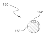
도 5는 본 발명에 따른 배수트랩의 승강축을 나타낸 측면도,
도 6은 도 5의 B-B선 단면도,
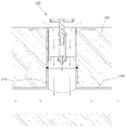
도 7은 본 발명에 따른 배수트랩의 결합상태를 나타낸 종단면도,
도 8은 본 발명에 따른 배수트랩의 작동상태를 나타낸 종단면도,
도 9는 본 발명에 따른 배수트랩의 배수상태를 나타낸 종단면도,
도 10은 종래의 배수트랩의 구성을 나타낸 분리 사시도,
도 11은 도 10의 덮개를 분리한 결합상태를 나타낸 종단면도.1 is a perspective view showing the appearance of the drain trap according to the invention,
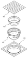
Figure 2 is an exploded perspective view showing the configuration of the drain trap according to the invention,
Figure 3 is a plan view showing the drainage induction passage of the drain trap according to the invention,
4 is a sectional view taken along line AA in Fig. 3,
Figure 5 is a side view showing the lifting shaft of the drain trap according to the invention,
6 is a cross-sectional view taken along line BB of FIG.
Figure 7 is a longitudinal cross-sectional view showing a coupling state of the drain trap according to the invention,
8 is a longitudinal sectional view showing an operating state of the drain trap according to the present invention;
9 is a longitudinal sectional view showing a drainage state of the drain trap according to the present invention;
10 is an exploded perspective view showing a configuration of a conventional drain trap;
Figure 11 is a longitudinal cross-sectional view showing a state in which the cover of Figure 10 removed.
이하, 첨부된 도면을 참조하여 본 발명에 따른 배수트랩의 바람직한 실시예를 상세하게 설명한다.Hereinafter, with reference to the accompanying drawings will be described in detail a preferred embodiment of the drain trap according to the present invention.
우선, 본 발명의 실시예는 여러 가지 형태로 변형될 수 있으며, 각 도면에서 동일한 부재는 동일한 참조부호로 나타내었고, 본 발명의 요지를 불필요하게 흐릴 수 있다고 판단되는 공지 기능 및 구성에 대한 상세한 설명은 생략됨에 유의하여야 한다.First, embodiments of the present invention can be modified in various forms, the same members in each of the drawings denoted by the same reference numerals, detailed description of known functions and configurations that are determined to unnecessarily obscure the subject matter of the present invention Note that is omitted.
도 1은 도 1은 본 발명에 따른 배수트랩의 외형을 나타낸 사시도이고, 도 2는 본 발명에 따른 배수트랩의 구성을 나타낸 분리 사시도이며, 도 3은 본 발명에 따른 배수트랩의 배수유도통을 나타낸 평면도이고, 도 4는 도 3의 A-A선 단면도이며, 도 5는 본 발명에 따른 배수트랩의 승강축을 나타낸 측면도이고, 도 6은 도 5의 B-B선 단면도이며, 도 7은 본 발명에 따른 배수트랩의 결합상태를 나타낸 종단면도이고, 도 8은 본 발명에 따른 배수트랩의 작동상태를 나타낸 종단면도이며, 도 9는 본 발명에 따른 배수트랩의 설치 및 배수상태를 나타낸 종단면도이다.1 is a perspective view showing the outline of the drain trap according to the invention, Figure 2 is an exploded perspective view showing the configuration of the drain trap according to the invention, Figure 3 is a drain induction passage of the drain trap according to the
본 발명에 따른 배수트랩(100)은, 도 1 내지 도 9에 도시된 것과 같이 본체(110), 배수유도통(120), 가이드부재(130), 스프링(140), 승강축(150), 가이드볼트(160), 덮개(170), 실리콘고무재 오링(180)을 포함하여 구성된다.The drain trap 100 according to the present invention, as shown in Figures 1 to 9, the
상기 본체(110)는 원통 형상으로 형성되어 제약, 화공약품 공장 등의 바닥면(300)의 하수공에 매설되는 것으로, 상단부 내부 둘레면에 제1 너트부(111)가 형성되어 있고, 상단부 바깥둘레면에 단차를 형성한 플랜지부(112)가 형성되어 있으며, 하부의 내부 둘레면에 제2 너트부(113)가 형성되어 배수관(200)의 볼트부(210)에 나사결합으로 연결설치된다.The
상기 배수유도통(120)은 컵 형상으로 형성되고 상기 본체(110)의 내부에 고정설치되어 배수통로를 제공하는 것으로, 상기 본체(110) 상부의 내부로 삽입되어 상단부의 바깥둘레면에 형성된 볼트부(121)가 상기 본체(110)의 제1 너트부(111)에 나사결합되고, 상면이 개방된 내부공간부(122)의 바닥면 중앙에 너트공(123)이 관통 형성되어 있으며, 상기 너트공(123)의 바깥 주위에 방사상으로 다수의 제1 배수공(124)이 관통 형성되어 있다. 이때, 도시는 하지 않았지만 상기 배수유도통(120)의 내부공간부(122) 바닥면에 망체를 설치하여 이물질을 걸러낼 수 있도록 구성할 수 있음은 물론이다.The
상기 가이드부재(130)는 상기 배수유도통(120)의 내부공간부(122) 바닥면 중앙에 형성된 너트공(123)에 가이드부재(130)의 하부에 형성된 볼트부(131)가 나사결합되어 수직으로 입설되고, 중앙 내부에 상면이 개방된 슬라이드홈(132)이 수직으로 길게 형성되어 있으며, 상기 슬라이드홈(133)의 바닥면 중앙에 상기 슬라이드홈(133)보다 직경이 작게 제2 배수공(133)이 관통 형성되어 있고, 상부의 바깥둘레면에 너트공(134)이 형성되어 있다.The
상기 스프링(140)은 일반적으로 가장 많이 사용되고 있는 코일형태의 탄성력을 가진 압축스프링으로, 상기 가이드부재(130)의 슬라이드홈(132)의 상부로 삽입되어 슬라이드홈(132)의 바닥면에 수직으로 설치된다.The
상기 승강축(150)은 상기 가이드부재(130)의 슬라이드홈(132) 상부를 통하여 승강 및 회전가능하게 삽입되며, 상기 슬라이드홈(132)의 상부로 외향 돌출되는 상단부에 볼트부(151)가 형성되어 있고, 상부측 바깥둘레면에 "ㄱ"자형 가이드홈(152)이 형성되어 있으며, 하부가 상기 스프링(140)에 삽입되어 탄력설치된다. 이때, 상기 승강축(150)의 하부는 상부보다 직경이 작게 형성되어 상단부의 단턱에 의해 상기 스프링(140)이 상부로 이탈되는 것을 방지하게 된다.The
상기 가이드볼트(160)는 상기 가이드부재(130)의 너트공(134)에 나사결합되며, 볼트부(161) 단부가 상기 승강축(150)의 "ㄱ"자형 가이드홈(152)에 걸리게 되어 상기 승강축(150)의 승강 및 정,역회전을 가이드하게 된다. 즉 상기 가이드볼트(160)의 볼트부(161) 단부는 상기 승강축(150)이 시계반대방향으로 회전(역회전)되어 최대한 상부로 상승하였을 때 "ㄱ"자형 가이드홈(152)의 세로방향 하단부가 걸리게 되어 상기 가이드부재(130)로부터 승강축(150)이 외부로 이탈되는 것을 방지하게 되고, 이와 반대로 상기 승강축(150)이 최대한 하강하여 시계방향으로 회전(정회전)되었을 때 "ㄱ"자형 가이드홈(152)의 가로방향 부분이 걸리게 되어 상기 가이드부재(130)로부터 승강축(150)이 상승되는 것을 방지하게 된다.The
상기 덮개(170)는 원판 형상으로 형성되어 상기 승강축(150)의 상단부에 일체로 고정설치되는 것으로, 상기 배수유도통(120)의 내부공간부(122) 상단면에 위치하게 되며, 중앙에 관통 형성된 너트공(171)에 상기 승강축(150)의 볼트부(151)가 나사결합되고, 바깥둘레면에 패킹홈(172)이 형성되어 배수통로를 형성하는 상기 배수유도통(120)의 내부공간부(122) 상단면을 상기 승강축(150)의 상승 및 하강에 의해 개방 및 폐쇄시키게 된다.The
상기 실리콘고무재 오링(180)은 상기 덮개(170)의 패킹홈(172)에 끼움 설치되어 상기 덮개(170)의 바깥둘레면과 상기 배수유도통(120)의 내부공간부(122) 상단면 사이를 밀폐시키게 된다.The silicone rubber O-
또한 상기 덮개(170)의 상면 중앙에 형성된 요입홈(173)에 덮개(170)의 너트공(171) 상면을 밀폐시키기 위한 실링부재(190)가 설치되어 있다. 이는 덮개(170)의 외관을 미려하게 하고, 청소용수를 배수처리할 때 상기 너트공(171)으로 오수가 유입되는 것을 방지하기 위함이다. 이때, 도시는 하지 않았지만 상기 덮개(170)의 중앙에 형성된 너트공(171)을 관통시키지 않고 저면 중앙에 상기 승강축(150)의 볼트부(151)가 나사결합되도록 홈 형태로 너트부를 형성하게 되면 상기 덮개(170)의 상면 중앙에 요입홈(173)을 형성할 필요가 없으므로 상기 실링부재(190)를 설치할 필요가 없게 됨은 당연하다.In addition, a sealing
상기 배수유도통(120)의 상면 전후로 컷팅홈(125)이 형성되어 있고, 상기 승강축(150)의 상부 바깥둘레면 전후로 컷팅홈(153)이 형성되어 있다. 이는 스패너, 드라이버 등의 나사체결공구를 이용하여 나사결합을 용이하게 하기 위함이다.Cutting
이와 같이 구성되는 본 발명에 따른 배수트랩(100)의 작용효과에 대하여 설명한다.The effect of the
본 발명에 따른 배수트랩(100)은 제약, 화공약품 공장 등에서 청소 후 발생하는 오수, 즉 머리카락 등의 이물질이 거의 포함되지 않은 오수를 배수처리할 때 덮개(170)를 손이나 발바닥을 이용하여 시계반대방향으로 회전(역회전)시키게 되면, 상기 덮개(10)의 회전과 동시에 승강축(150)의 "ㄱ"자형 가이드홈(152)이 가이드볼트(160)의 볼트부(161) 단부에 의해 가로방향으로 가이드 되어 회전되면서 "ㄱ"자형 가이드홈(152)의 세로방향 상단부, 즉 "ㄱ"자형 가이드홈(152)의 절곡된 모서리 부분이 가이드볼트(160)의 볼트부(161) 단부에 위치되었을 때 스프링(140)의 탄성력에 의해 승강축(150)을 수직으로 상승시킴과 동시에 실리콘고무재 오링(180)이 끼움 설치된 덮개(170)가 상승하게 된다.The
이때, 상기 가이드볼트(160)의 볼트부(161) 단부에 의해 상기 승강축(150)이 "ㄱ"자형 가이드홈(152)에 의해 수직으로 가이드 되면서 신속하게 상승하게 되고, "ㄱ"자형 가이드홈(152)의 세로방향 하단부가 걸리게 되면서 상기 승강축(150)이 스프링(140)의 탄성력에 의한 수직 상승이 정지되어 덮개(170)가 더 이상 상승하게 되는 것을 저지하게 된다.At this time, the lifting
상기 덮개(170)가 상승하게 되면 도 8 및 도 9에 도시된 바와 같이, 배수통로를 제공하는 배수유도통(120)의 내부공간부(122) 상단면을 개방시키게 되어 청소 후 발생하는 오수가 상기 배수유도통(120)의 내부공간부(122)로 유입되면서 다수의 제1 배수공(124)을 통해 배수관(200)으로 신속하게 배출이 이루어지게 된다. 또한 상기 승강축(150)과 가이드부재(130)의 슬라이드홈(132) 사이를 통해 상기 슬라이드홈(132)으로 유입되는 오수는 제2 배수공(133)을 통해 배수관(200)으로 신속하게 배출이 이루어지게 된다.When the
따라서, 배수통로를 제공하는 배수유도통(120)의 내부공간부(122)로 유입되는 오수는 상기 배수유도통(120)의 다수의 제1 배수공(124)과 가이드부재(130)의 제2 배수공(133)에 의해 신속하게 배출이 이루어지게 되므로 배수트랩(100) 내에 오수가 잔존할 염려가 전혀 발생하지 않게 되어 배수트랩(100)을 쾌적한 상태에서 사용할 수 있다.Therefore, the sewage flowing into the
그리고 오수의 배수처리가 완료된 후 덮개(170)를 완전히 누르면서 시계방향으로 회전(정회전)시키게 되면, 상기 승강축(150)의 "ㄱ"자형 가이드홈(152)이 가이드볼트(160)의 볼트부(161) 단부를 따라 수직으로 하강하면서 가이드볼트(160)의 볼트부(161) 단부에 "ㄱ"자형 가이드홈(152)의 상단부 가로방향 부분이 걸리게 되어 상기 승강축(150)이 상승되는 것을 방지함과 동시에 실리콘고무재 오링(180)이 끼움 설치된 덮개(170)가 원위치로 복귀하게 되어 배수통로를 제공하는 배수유도통(120)의 내부공간부(122) 상단면을 밀폐되게 폐쇄함으로써 배수관(200)으로부터 역류하는 하수의 악취를 완전히 차단할 수 있다. 따라서, 도 7에 도시된 바와 같이, 상기 덮개(170)를 시계반대방향으로 회전시키기 전에는 배수통로를 제공하는 배수유도통(120)의 내부공간부(122) 상단면이 개방되지 않으므로 안전하게 배수관(200)으로부터 역류하는 하수의 악취를 보다 효과적으로 차단할 수 있게 된다.And when the waste water treatment is completed and rotated clockwise (forward rotation) while fully pressing the
또한, 상기 본체(110)로부터 배수유도통(120), 가이드부재(130), 스프링(140), 승강축(150), 가이드볼트(160), 덮개(170), 실리콘고무재 오링(180)을 매우 용이하게 분해 및 조립할 수 있으므로 유지보수를 간편하게 할 수 있다.In addition, the
이상과 같이 본 발명의 바람직한 실시예에 대해 첨부된 도면을 참조로 하여 설명하였으나, 본 발명은 상술한 특정의 실시예에 의해 한정되는 것이 아니며, 본 발명이 속하는 기술분야에서 통상의 지식을 가진 자에 의해 본 발명의 기술적 사상과 이하에서 기재되는 특허청구범위의 균등범위 내에서 다양한 형태의 수정 및 변형이 가능함은 물론이다.While the present invention has been particularly shown and described with reference to exemplary embodiments thereof, it is clearly understood that the same is by way of illustration and example only and is not to be construed as limited to the particular details of the embodiments set forth herein. It will be understood by those skilled in the art that various changes in form and details may be made therein without departing from the spirit and scope of the present invention as defined by the appended claims.
100 : 배수트랩 110 : 본체
111 : 제1 너트부 112 : 플랜지부
113 : 제2 너트부 120 : 배수유도통
121 : 볼트부 122 : 내부공간부
123 : 너트공 124 : 제1 배수공
125 : 컷팅홈 130 : 가이드부재
131 : 볼트부 132 : 슬라이드홈
133 : 제2 배수공 134 : 너트공
140 : 스프링 150 : 승강축
151 : 볼트부 152 : 가이드홈
153 : 컷팅홈 160 : 가이드볼트
161 : 볼트부 170 : 덮개
171 : 너트공 172 : 패킹홈
173 : 요입홈 180 : 실리콘고무재 오링
190 : 실링부재 200 : 배수관
210 : 볼트부 300 : 바닥면100: drain trap 110: main body
111: first nut portion 112: flange portion
113: second nut portion 120: drainage guide
121: bolt portion 122: internal space portion
123: nut ball 124: first drain hole
125: cutting groove 130: guide member
131: bolt portion 132: slide groove
133: second drain hole 134: nut ball
140: spring 150: lifting shaft
151: bolt portion 152: guide groove
153: cutting groove 160: guide bolt
161: bolt portion 170: cover
171: nut ball 172: packing groove
173: recess groove 180: silicone rubber O-ring
190 sealing
210: bolt portion 300: bottom surface
Claims (3)
상기 본체(110) 상부의 내부로 삽입되어 상단부의 바깥둘레면에 형성된 볼트부(121)가 상기 본체(110)의 제1 너트부(111)에 나사결합되고, 상면이 개방된 내부공간부(122)의 바닥면 중앙에 너트공(123)이 관통 형성되며, 상기 너트공(123)의 바깥 주위에 방사상으로 다수의 제1 배수공(124)이 관통 형성되는 컵 형상의 배수유도통(120)과;
상기 배수유도통(120)의 내부공간부(122) 바닥면 중앙의 너트공(123)에 하부에 형성된 볼트부(131)가 나사결합되어 수직으로 입설되고, 중앙 내부에 상면이 개방된 슬라이드홈(132)이 수직으로 길게 형성되며, 상기 슬라이드홈(133)의 바닥면 중앙에 제2 배수공(133)이 관통 형성되고, 상부의 바깥둘레면에 너트공(134)이 형성되는 가이드부재(130)와;
상기 가이드부재(130)의 슬라이드홈(132)의 상부로 삽입되어 슬라이드홈(132)의 바닥면에 수직으로 설치되는 스프링(140)과;
상기 가이드부재(130)의 슬라이드홈(132) 상부를 통하여 승강 및 회전가능하게 삽입되며, 상기 슬라이드홈(132)의 상부로 외향 돌출되는 상단부에 볼트부(151)가 형성되고, 상부측 바깥둘레면에 "ㄱ"자형 가이드홈(152)이 형성되어 하부가 상기 스프링(140)에 삽입되어 탄력설치되는 승강축(150)과;
상기 가이드부재(130)의 너트공(134)에 나사결합되며, 볼트부(161)의 단부가 상기 승강축(150)의 "ㄱ"자형 가이드홈(152)에 걸리게 되어 상기 승강축(150)의 승강 및 정,역회전을 가이드하게 되는 가이드볼트(160)와;
상기 배수유도통(120)의 내부공간부(122) 상단면에 위치하게 되며, 중앙의 너트공(171)에 상기 승강축(150)의 볼트부(151)가 나사결합되고, 바깥둘레면에 패킹홈(172)이 형성되어 상기 배수유도통(120)의 내부공간부(122) 상단면을 상기 승강축(150)의 상승 및 하강에 의해 개방 및 폐쇄시키게 되는 원판 형상의 덮개(170)와;
상기 덮개(170)의 패킹홈(172)에 끼움 설치되어 상기 덮개(170)의 바깥둘레면과 상기 배수유도통(120)의 내부공간부(122) 상단면 사이를 밀폐시키는 실리콘고무재 오링(180)을 포함하여 구성되는 것을 특징으로 하는 배수트랩.The first nut part 111 is formed on the inner circumferential surface of the upper end, and the flange portion 112 having a step formed on the outer circumferential surface of the upper end is formed, and the second nut part 113 formed on the inner circumferential surface of the lower part has a drain pipe. A cylindrical main body 110 connected to the bolt portion 210 of the 200 by screwing;
The bolt portion 121 inserted into the upper portion of the main body 110 and formed on the outer circumferential surface of the upper end is screwed to the first nut part 111 of the main body 110, and the inner space portion having the upper surface opened ( A nut hole 123 is formed in the center of the bottom surface of the 122, and a cup-shaped drainage induction pipe 120 in which a plurality of first drain holes 124 penetrates radially around the outside of the nut hole 123 is formed. and;
A bolt groove 131 formed at a lower portion is vertically screwed into the nut hole 123 at the center of the bottom surface of the inner space portion 122 of the drain induction pipe 120, and a slide groove having an upper surface open in the center thereof. 132 is formed vertically long, the guide member 130, the second drain hole 133 is formed in the center of the bottom surface of the slide groove 133, the nut hole 134 is formed on the outer peripheral surface of the upper portion )Wow;
A spring 140 inserted into an upper portion of the slide groove 132 of the guide member 130 and installed vertically on a bottom surface of the slide groove 132;
Lifted and rotatably inserted through an upper portion of the slide groove 132 of the guide member 130, a bolt portion 151 is formed in the upper end portion protruding outward to the upper portion of the slide groove 132, the upper outer circumference A lifting shaft 150 having a “a” shaped guide groove 152 formed on a surface thereof, the lower portion of which is inserted into the spring 140 to be elastically installed;
Screwed to the nut hole 134 of the guide member 130, the end of the bolt portion 161 is caught in the "a" shaped guide groove 152 of the lifting shaft 150, the lifting shaft 150 Guide bolts 160 to guide the lifting and forward, reverse rotation of the;
Located in the upper surface of the inner space portion 122 of the drain induction pipe 120, the bolt portion 151 of the lifting shaft 150 is screwed to the nut hole 171 in the center, the outer peripheral surface A packing groove 172 is formed and a disc-shaped cover 170 which opens and closes the upper surface of the inner space portion 122 of the drainage induction pipe 120 by raising and lowering the lifting shaft 150. ;
Silicone rubber O-ring is installed in the packing groove 172 of the cover 170 to seal between the outer circumferential surface of the cover 170 and the upper surface of the inner space portion 122 of the drain induction pipe 120 ( 180) drain trap, characterized in that configured to include.
상기 덮개(170)의 상면 중앙에 형성된 요입홈(173)에 덮개(170)의 너트공(171) 상부를 밀폐시키기 위한 실링부재(190)가 더 포함되는 것을 특징으로 하는 배수트랩.The method of claim 1,
Drain trap characterized in that it further comprises a sealing member (190) for sealing the upper portion of the nut hole (171) of the cover 170 in the recess groove (173) formed in the center of the upper surface of the cover (170).
상기 배수유도통(120)의 상면 전후로 컷팅홈(125)이 형성되고, 상기 승강축(150)의 상부 바깥둘레면 전후로 컷팅홈(153)이 형성되는 것을 특징으로 하는 배수트랩.The method of claim 1,
Cutting groove 125 is formed before and after the upper surface of the drain induction pipe 120, the cutting trap characterized in that the cutting groove 153 is formed before and after the upper outer peripheral surface of the lifting shaft 150.
Priority Applications (1)
| Application Number | Priority Date | Filing Date | Title |
|---|---|---|---|
| KR1020120045090A KR20130122061A (en) | 2012-04-30 | 2012-04-30 | Drain trap |
Applications Claiming Priority (1)
| Application Number | Priority Date | Filing Date | Title |
|---|---|---|---|
| KR1020120045090A KR20130122061A (en) | 2012-04-30 | 2012-04-30 | Drain trap |
Publications (1)
| Publication Number | Publication Date |
|---|---|
| KR20130122061A true KR20130122061A (en) | 2013-11-07 |
Family
ID=49851916
Family Applications (1)
| Application Number | Title | Priority Date | Filing Date |
|---|---|---|---|
| KR1020120045090A KR20130122061A (en) | 2012-04-30 | 2012-04-30 | Drain trap |
Country Status (1)
| Country | Link |
|---|---|
| KR (1) | KR20130122061A (en) |
Cited By (3)
| Publication number | Priority date | Publication date | Assignee | Title |
|---|---|---|---|---|
| KR200481812Y1 (en) * | 2015-10-02 | 2016-11-22 | 주식회사 천일 | Sink bowl with food seperation garbage basket |
| KR20180115589A (en) * | 2017-04-13 | 2018-10-23 | 남의강 | Drain valve for washstand |
| CN111663627A (en) * | 2020-06-24 | 2020-09-15 | 北京爱德姆能源科技有限公司 | Odor-resistant piston device for hotel drain pipe |
-
2012
- 2012-04-30 KR KR1020120045090A patent/KR20130122061A/en not_active Application Discontinuation
Cited By (3)
| Publication number | Priority date | Publication date | Assignee | Title |
|---|---|---|---|---|
| KR200481812Y1 (en) * | 2015-10-02 | 2016-11-22 | 주식회사 천일 | Sink bowl with food seperation garbage basket |
| KR20180115589A (en) * | 2017-04-13 | 2018-10-23 | 남의강 | Drain valve for washstand |
| CN111663627A (en) * | 2020-06-24 | 2020-09-15 | 北京爱德姆能源科技有限公司 | Odor-resistant piston device for hotel drain pipe |
Similar Documents
| Publication | Publication Date | Title |
|---|---|---|
| KR101415336B1 (en) | A drain trap | |
| KR20120112409A (en) | A non-return valve assembly of the pivoting flap type, typically for insertion in floor drains | |
| KR20130122061A (en) | Drain trap | |
| KR101264017B1 (en) | Drain open/close control apparatus for having a function of protection against the reek of sewage and backflow | |
| KR101621682B1 (en) | An apparatus for a bad smell reflux prevention | |
| KR20080032652A (en) | Water pressurized manual lavatory de-blocking pump | |
| KR101354072B1 (en) | Drain trap | |
| KR100701785B1 (en) | Trap installed atdrain pipe for preventing bad smell in an apartment house | |
| KR101178011B1 (en) | Drain trap | |
| KR20130045791A (en) | Drain trap for bed smell prevention | |
| AU2014100933A4 (en) | Apparatus and Method for Conserving and Filtering Water | |
| KR20180049886A (en) | Waste trap | |
| KR101526150B1 (en) | Water sealing type waste trap having filtration net | |
| KR101944377B1 (en) | Drain valve for washstand | |
| KR20190002468U (en) | Drain trap to block malodor inflow and sewer backflow by minimizing foreign matter trapping | |
| KR101594899B1 (en) | A draining trap apparatus for a washstand | |
| KR102037640B1 (en) | a Drainage flange for toilet bowl | |
| KR100891131B1 (en) | Washstand drainage system | |
| KR200480200Y1 (en) | The drain for pop-up valve of a washbowl | |
| KR20120041541A (en) | Multi pipe joint apparatus having water sealing function | |
| KR200260320Y1 (en) | Check valve | |
| KR20100011172U (en) | Drainage unit | |
| CN205369500U (en) | Prevent outside floor drain that discharges of peculiar smell | |
| KR200188214Y1 (en) | Trap | |
| KR200244689Y1 (en) | drain tray is for a bed smell upstream curret to hold |
Legal Events
| Date | Code | Title | Description |
|---|---|---|---|
| A201 | Request for examination | ||
| E902 | Notification of reason for refusal | ||
| E902 | Notification of reason for refusal | ||
| E601 | Decision to refuse application |