KR20130103988A - A chair - Google Patents
A chair Download PDFInfo
- Publication number
- KR20130103988A KR20130103988A KR1020120025076A KR20120025076A KR20130103988A KR 20130103988 A KR20130103988 A KR 20130103988A KR 1020120025076 A KR1020120025076 A KR 1020120025076A KR 20120025076 A KR20120025076 A KR 20120025076A KR 20130103988 A KR20130103988 A KR 20130103988A
- Authority
- KR
- South Korea
- Prior art keywords
- backrest
- fixed
- chair
- rotatable
- support
- Prior art date
Links
Images


Classifications
-
- A—HUMAN NECESSITIES
- A47—FURNITURE; DOMESTIC ARTICLES OR APPLIANCES; COFFEE MILLS; SPICE MILLS; SUCTION CLEANERS IN GENERAL
- A47C—CHAIRS; SOFAS; BEDS
- A47C7/00—Parts, details, or accessories of chairs or stools
- A47C7/36—Support for the head or the back
- A47C7/40—Support for the head or the back for the back
- A47C7/44—Support for the head or the back for the back with elastically-mounted back-rest or backrest-seat unit in the base frame
- A47C7/443—Support for the head or the back for the back with elastically-mounted back-rest or backrest-seat unit in the base frame with coil springs
- A47C7/444—Support for the head or the back for the back with elastically-mounted back-rest or backrest-seat unit in the base frame with coil springs of torsion type
-
- A—HUMAN NECESSITIES
- A47—FURNITURE; DOMESTIC ARTICLES OR APPLIANCES; COFFEE MILLS; SPICE MILLS; SUCTION CLEANERS IN GENERAL
- A47C—CHAIRS; SOFAS; BEDS
- A47C1/00—Chairs adapted for special purposes
- A47C1/02—Reclining or easy chairs
- A47C1/022—Reclining or easy chairs having independently-adjustable supporting parts
- A47C1/024—Reclining or easy chairs having independently-adjustable supporting parts the parts, being the back-rest, or the back-rest and seat unit, having adjustable and lockable inclination
-
- A—HUMAN NECESSITIES
- A47—FURNITURE; DOMESTIC ARTICLES OR APPLIANCES; COFFEE MILLS; SPICE MILLS; SUCTION CLEANERS IN GENERAL
- A47C—CHAIRS; SOFAS; BEDS
- A47C7/00—Parts, details, or accessories of chairs or stools
- A47C7/02—Seat parts
Landscapes
- Health & Medical Sciences (AREA)
- Dentistry (AREA)
- General Health & Medical Sciences (AREA)
- Chairs Characterized By Structure (AREA)
Abstract
Description
본 발명은 회동가능한 등받이가 구비된 의자에 관한 것으로서, 더욱 구체적으로 설명하면, 지지다리와 등받이의 연결부분에 회동부가 형성되어 사용자가 의자에 앉아 등받이에 등을 기대면 가압에 의해 회동부의 내측 탄성스프링이 작동되어 등받이가 회동 되게 되므로 사용자는 회동된 등받이에 편안하게 등을 기대는 것이 가능하게 되며, 가압이 해제되면 회동부 내측에 설치된 탄성스프링의 탄성복원력에 의해 회동부가 원상태로 복귀되면서 등받이 또한 원상태로 복귀하는 것이 가능하게 되고, 상기 회동부의 구조가 간단하게 되어 제조가 간편하게 되므로 제조인력과 제조비용이 절감되는 것이 가능하며, 좌판의 후단부가 상기 등받이방향으로 상방으로 절곡되어 연장 형성된 허리지지부가 형성되므로 등받이가 회동되어 뒤로 젖혀지게 되더라도 사용자의 허리를 받쳐주게 되므로 사용자의 등은 등받이에 의해 받쳐지게 되고 허리는 좌판의 허리지지부에 의해 받쳐지게 되므로 사용자는 편안한 자세로 휴식을 취하는 것이 가능하게 되는 회동가능한 등받이가 구비된 의자에 관한 것이다. The present invention relates to a chair provided with a pivotable backrest. More specifically, the pivoting portion is formed at a connection portion between the support leg and the backrest so that when the user sits on the chair and leans back against the backrest, the inner part of the pivoting part is pressurized. The elastic spring is activated so that the backrest can be rotated, so that the user can rest on the back comfortably on the pivoted backrest. In addition, it is possible to return to the original state, and the structure of the rotating part is simplified to simplify the manufacturing manpower and manufacturing cost can be reduced, and the rear end of the seat plate is bent upwards in the backrest direction and extended Because the support is formed, even if the backrest is pivoted back Since the user's back is supported by the user's back and the back is supported by the waist support of the seat plate, the user is provided with a pivotable backrest that enables the user to relax in a comfortable posture. .
일반적으로, 종래의 의자는 좌판의 저면에 일단부가 고정된 지지프레임의 타단부에 등받이가 고정설치된다.In general, the back of the conventional chair is fixed to the other end of the support frame, one end is fixed to the bottom of the seat plate.
그러나, 이와 같은 종래의 의자는 사용자가 장시간 앉아 있는 관계로 휴식을 취하기 위하여 등받이를 뒤로 젖히면 허리가 위치되는 부분이 없어지게 되므로 오히려 더 불편하게 되고 편안한 휴식을 취하기 위해서는 의자의 등받이의 허리 부분에 보조쿠션을 넣어 사용하여야 하는 불편한 문제점이 있었다.However, such a conventional chair is more uncomfortable because the user is sitting for a long time sitting the back back in order to take a rest, so that the back is no longer uncomfortable and in order to take a rest to rest the back of the chair back There was an uncomfortable problem to use the cushion.
이러한 종래의 문제점을 해결하기 위하여, 대한민국 특허등록 제1032981호의 '의자용 등받이 회전장치'가 안출되었으나, 이러한 종래의 의자용 등받이 회전장치는, 의자의 팔걸이와 등받이의 연결부위에 장착되며, 사용자가 의자에 앉아 기대면 가압에 의해 등받이가 회전되도록 회전 작동되고, 가압이 해제되면 등받이가 곧바로 원상태로 복원될 수 있도록 고무 또는 우레탄소재로된 탄성체가 사용되므로 그 구조가 복잡하여 제조가 난해하게 되고 고무 또는 우레탄소재로된 탄성체가 등받이의 잦은 작동에 의해 쉽게 파손되는 경우가 빈번하게 발생하게 되어 회전장치의 원할한 작동이 어렵게 되는 문제점이 있었고, 또한, 파손된 탄성체를 교체하여야 하므로 유지보수가 필요하게 되어 유지보수에 따른 비용이 발생하게 되는 문제점이 있었다.In order to solve such a conventional problem, the 'backrest rotation device for chair' of the Republic of Korea Patent Registration No. 1032981 has been devised, but such a conventional chair back rotation device is mounted on the connection of the armrest and the backrest of the chair, the user When you sit on the chair, the backrest is rotated by pressurization, and when the pressure is released, the backrest can be restored to its original state immediately. Or the elastic body made of urethane material is often broken easily by frequent operation of the backrest, so that the smooth operation of the rotating device is difficult, and the damaged elastic body needs to be replaced, thus requiring maintenance. There was a problem that the cost of the maintenance occurs.
본 발명의 목적은, 이러한 종래의 문제점을 해결하기 위한 것으로서, 더욱 구체적으로 설명하면, 지지다리와 등받이의 연결부분에 회동부가 형성되어 사용자가 의자에 앉아 등받이에 등을 기대면 가압에 의해 회동부의 내측 탄성스프링이 작동되어 등받이가 회동 되게 되므로 사용자는 회동된 등받이에 편안하게 등을 기대는 것이 가능하게 되며, 가압이 해제되면 회동부 내측에 설치된 탄성스프링의 탄성복원력에 의해 회동부가 원상태로 복귀되면서 등받이 또한 원상태로 복귀하는 것이 가능하게 되고, 상기 회동부의 구조가 간단하게 되어 제조가 간편하게 되므로 제조인력과 제조비용이 절감되는 것이 가능하며, 좌판의 후단부가 상기 등받이방향으로 상방으로 절곡되어 연장 형성된 허리지지부가 형성되므로 등받이가 회동되어 뒤로 젖혀지게 되더라도 사용자의 허리를 받쳐주게 되므로 사용자의 등은 등받이에 의해 받쳐지게 되고 허리는 좌판의 허리지지부에 의해 받쳐지게 되므로 사용자는 편안한 자세로 휴식을 취하는 것이 가능한 회동가능한 등받이가 구비된 의자를 제공하는 것이다.An object of the present invention is to solve such a conventional problem, and more specifically, the rotating part is formed at the connection portion of the support leg and the backrest, and the rotating part is pressurized when the user sits on a chair and leans back on the backrest. Since the inner elastic spring of the backrest is operated so that the user can lean back comfortably on the pivoted backrest, and when the pressure is released, the rotating part returns to its original state by the elastic restoring force of the elastic spring installed inside the rotating part. The backrest is also able to return to its original state, and the structure of the pivoting portion is simplified, which makes the manufacturing simpler, thereby reducing manufacturing manpower and manufacturing cost, and the rear end of the seat plate is bent upward in the backrest direction and extended. The back support is formed so that the backrest is pivoted Even if the user's back is supported by the user's back is supported by the back and the waist is supported by the waist support of the seat plate is to provide a chair with a pivotable backrest that allows the user to relax in a comfortable posture. .
본 발명의 이러한 목적은, 허리지지부가 형성된 좌판과, 상기 좌판이 상부에 고정설치되며 지지다리가 형성된 의자프레임과, 상기 의자프레임의 지지다리에 회동부에 의해 고정되어 회동가능하게 고정된 등받이로 구성된 회동가능한 등받이가 구비된 의자에 있어서, 상기 회동부는 의자프레임의 후단부에 형성된 지지다리의 상단에 형성되어 등받이가 회동가능하도록 상기 등받이에 형성된 가동본체가 삽입고정되는 고정본체와, 상기 고정본체에 삽입고정되어 회동가능하도록 탄성스프링이 설치되며 등받이의 양측에 형성된 가동본체를 포함하는 본 발명의 실시예에 따른 회동가능한 등받이가 구비된 의자에 의하여 달성된다.This object of the present invention is a seat plate formed with a waist support, the seat plate is fixed to the upper seat and the support frame is formed, and the backrest is fixed to the support leg of the chair frame is pivotally fixed A chair having a rotatable backrest configured, wherein the rotatable part is formed at an upper end of a support leg formed at a rear end of the chair frame, and a fixed main body into which the movable body formed on the backrest is inserted and fixed so that the backrest is rotatable; It is achieved by a chair equipped with a rotatable backrest according to an embodiment of the present invention including a movable body formed on both sides of the backrest and is installed to be rotatable to be inserted into.
본 발명의 일 실시예에 따른 회동가능한 등받이가 구비된 의자는 첨부된 도면을 참고로 하여 이하에 상세히 기술되는 실시예에 의하여 그 특징 및 장점들을 명백히 이해할 수 있을 것이다.Chair equipped with a rotatable backrest according to an embodiment of the present invention will be clearly understood its features and advantages by the embodiments described in detail below with reference to the accompanying drawings.
본 발명의 일실시예에 따른 회동가능한 등받이가 구비된 의자는, 지지다리와 등받이의 연결부분에 회동부가 형성되어 사용자가 의자에 앉아 등받이에 등을 기대면 가압에 의해 회동부의 내측 탄성스프링이 작동되어 등받이가 회동 되게 되므로 사용자는 회동된 등받이에 편안하게 등을 기대는 것이 가능하게 되며, 가압이 해제되면 회동부 내측에 설치된 탄성스프링의 탄성복원력에 의해 회동부가 원상태로 복귀되면서 등받이 또한 원상태로 복귀하는 것이 가능하게 되고, 상기 회동부의 구조가 간단하게 되어 제조가 간편하게 되므로 제조인력과 제조비용이 절감되는 것이 가능하며, 좌판의 후단부가 상기 등받이방향으로 상방으로 절곡되어 연장 형성된 허리지지부가 형성되므로 등받이가 회동되어 뒤로 젖혀지게 되더라도 사용자의 허리를 받쳐주게 되므로 사용자의 등은 등받이에 의해 받쳐지게 되고 허리는 좌판의 허리지지부에 의해 받쳐지게 되므로 사용자는 편안한 자세로 휴식을 취하는 것이 가능하게 되는 우수한 효과가 있다.In the chair having a rotatable backrest according to an embodiment of the present invention, a pivoting portion is formed at a connection portion between the support leg and the backrest so that when the user sits on the chair and leans back against the backrest, the inner elastic spring of the pivoting portion is pressurized. Since the backrest is rotated by operation, the user can lean back comfortably on the pivoted backrest.When the pressure is released, the backrest is returned to its original state by the elastic restoring force of the elastic spring installed inside the pivoting part. It is possible to return, and the structure of the rotating part is simplified to simplify the manufacturing manpower and manufacturing cost can be reduced, and the rear end of the seat plate is bent upwards in the backrest direction to form a waist support So even if the backrest is pivoted back, it will support the user's waist. Since the user, such as is be sustained by the back waist so it is sustained by the support portion of the back seat plate user has the excellent effect that makes it possible to relax in a comfortable position.
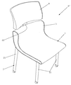
도 1은 본 발명의 제1실시예에 따른 의자의 사시도
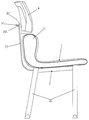
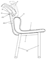
도 2는 도 1에 도시된 의자의 분해사시도
도 3은 본 발명의 제1실시예에 따른 의자의 회동부의 조립단계를 나타낸 순서도
도 4a, 4b는 본 발명의 제1실시예에 따른 의자의 등받이의 작동상태를 나타낸 개략적인 작동도
도 5는 본 발명의 제2실시예에 따른 의자의 사시도
도 6a, 6b는 도 5에 도시된 의자의 등받이의 작동상태를 나타낸 개략적인 작동도
도 7은 본 발명의 제3실시예에 따른 의자의 사시도
도 8a, 8b는 도 7에 도시된 의자의 등받이의 작동상태를 나타낸 개략적인 작동도1 is a perspective view of a chair according to a first embodiment of the present invention;
2 is an exploded perspective view of the chair shown in FIG.
Figure 3 is a flow chart showing the assembly step of the rotating part of the chair according to the first embodiment of the present invention
Figure 4a, 4b is a schematic operation diagram showing the operating state of the back of the chair according to the first embodiment of the present invention
5 is a perspective view of a chair according to a second embodiment of the present invention;
Figure 6a, 6b is a schematic operation diagram showing the operating state of the backrest of the chair shown in FIG.
7 is a perspective view of a chair according to a third embodiment of the present invention;
8A and 8B are schematic operation diagrams showing an operating state of the backrest of the chair shown in FIG.
이하, 첨부된 도면을 참고로 하여 본 발명의 회동가능한 등받이가 구비된 의자를 보다 상세하게 설명하기로 한다.Hereinafter, with reference to the accompanying drawings will be described in more detail a chair provided with a rotatable backrest of the present invention.
이에 앞서, 본 발명에 대한 명세서 및 청구범위에 사용된 용어는 통상적이거나 사전적인 의미로 한정해서 해석되어서는 아니 되며, 발명자는 그 자신의 발명을 가장 최선의 방법으로 설명하기 위해서 용어의 개념을 적절하게 정의할 수 있다는 원칙에 입각하여 본 발명의 기술적 사상에 부합하는 의미와 개념으로 해석되어야만 한다. Prior to this, the terms used in the specification and claims should not be construed as limited to ordinary or dictionary meanings, and the inventor must design the concept of the term appropriately in order to describe his invention in the best way. It should be interpreted as meaning and concept consistent with the technical idea of the present invention.
따라서, 본 명세서에 기재된 일실시예와 도면에 도시된 구성은 본 발명의 가장 바람직한 일실시예에 불과할 뿐이고 본 발명의 기술적 사상을 모두 대변하는 것은 아니므로 본 출원시점에 있어서 이들은 대체할 수 있는 다양한 균등물과 변형 예들이 있을 수 있음을 이해하여야 한다. Therefore, the embodiment described in the present specification and the constitution shown in the drawings are only the most preferred embodiments of the present invention and do not represent all the technical ideas of the present invention. Therefore, at the time of this application, It is to be understood that equivalents and modifications are possible.
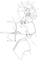
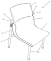
본 발명의 제 1실시예에 따른 회동가능한 등받이가 구비된 의자(A)는, 도 1내지 도 4에 도시된 바와 같이, 허리지지부(11)가 형성된 좌판(1)과, 상기 좌판(1)이 상부에 고정설치되며 지지다리(21)가 형성된 의자프레임(2)과, 상기 의자프레임(2)의 지지다리(21)에 회동부(3)에 의해 고정되어 회동가능하게 고정된 등받이(4)로 구성된 회동가능한 등받이가 구비된 의자(A)에 있어서, 상기 회동부(3)는 의자프레임(2)의 후단부에 형성된 지지다리(21)의 상단에 형성되어 등받이(4)가 회동가능하도록 상기 등받이(4)에 형성된 가동본체(32)가 삽입고정되는 고정본체(31)와, 상기 고정본체(31)에 삽입고정되어 회동가능하도록 탄성스프링(33)이 설치되며 등받이(4)의 양측에 형성된 가동본체(32)를 포함한다.Chair (A) is provided with a rotatable backrest according to the first embodiment of the present invention, as shown in Figure 1 to 4, the
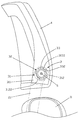
상기 회동부(3)의 고정본체(31)는, 하부에 의자프레임(2)의 후단부에 형성된 지지다리(21)의 상단에 고정되도록 고정지지부(311)가 형성되고, 상기 고정지지부(311)의 상부에는 등받이(4)에 형성된 가동본체(32)가 삽입되도록 원통 형상으로 형성되어 내벽에 가동본체(32)의 탄성스프링(33)이 걸려 가동본체(32)의 돌기작동홈(321)에 삽입되는 걸림돌기(3122)가 형성된 삽입공간(3121)이 형성되며 중앙에는 고정나사(5)가 관통되는 관통공(313)이 형성된 고정체(312)가 형성된다. The
상기 회동부(3)의 가동본체(32)는, 상기 고정본체(31)의 삽입공간(3121)에 삽입되도록 원통형상으로 형성되어 외면에 고정본체(31)의 삽입공간(3121) 내벽에 형성된 걸림돌기(3122)가 삽입되어 가동본체(32)의 회동시 상기 가동본체(32)가 일정각도 회동 후 상기 걸림돌기(3122)에 걸려 회동이 제한되도록 돌기작동홈(321)이 형성되고 상기 돌기작동홈(321)의 외측으로 돌기작동홈(321)의 작동거리보다 길게 형성되어 상기 고정본체(31)의 걸림돌기(3122)에 걸린 탄성스프링(33)의 작동거리를 제공하는 스프링작동홈(322)이 형성되고 상기 스프링작동홈(322)의 내측에 탄성스프링(33)이 고정되도록 핀고정홈(3231)이 형성된 원환형의 스프링배치홈(323)이 형성되며 중앙에 상기 고정본체(31)의 관통공(3121)을 통해 삽입된 고정나사(5)가 고정되는 나사고정공(324)이 형성되어 등받이(4)의 측면 하단부에 형성된다. The
상기 가동본체(32)의 돌기작동홈(321)은, 가동본체(32)의 외면에 호형상으로 형성되어 고정본체(31)에 삽입시 상기 고정본체(31)의 삽입공간(3121) 내벽에 형성된 걸림돌기(3122)가 삽입된 상태에서 가동본체(32)가 일정 각도로 회동 가능하도록 그 회동거리를 제공하게 되며 가동본체(32)의 회동시 일정각도 회동 후 고정본체(31)의 걸림돌기(3122)에 걸려 회동이 제한되게 된다. The
상기 가동본체(32)의 스프링작동홈(322)은, 가동본체(32)의 외면에 상기 돌기작동홈(321)의 외측으로 호형상으로 형성되어 가동본체(32)에 설치된 탄성스프링(33)의 가동핀부(332)가 배치된 상태에서 탄성스프링(33)이 일정각도 회동 가능하도록 그 회동거리를 제공하게 되며 탄성스프링(33)의 회동시 일정각도 회동 후 상기 탄성스프링(33)의 가동핀부(332)가 걸려 회동이 제한되게 된다.The spring actuating
상기 가동본체(32)의 스프링배치홈(323)은, 상기 스프링작동홈(322)의 내측에 형성되어 상기 탄성스프링(33)이 배치되도록 탄성스프링(33)의 형상과 동일하게 원환형으로 형성되며 내측에 탄성스프링(33)의 일측 고정핀부(331)가 고정되도록 핀고정홈(3231)이 형성된다.The
상기 탄성스프링(33)은, 원환형으로 형성되며 상기 가동본체(32)의 스프링배치홈(323) 내측에 형성된 핀고정홈(3231)에 끼워져 고정되록 일단부가 절곡되어 고정핀부(331)가 형성되고 타단부는 탄성스프링(33)이 스프링배치홈(323)에 설치된 상태에서 고정본체(31)의 삽입공간(3121)에 삽입시 상기 삽입공간(3121) 내벽에 형성된 걸림돌기(3122)가 걸리도록 절곡되어 가동핀부(332)가 형성된다.The
상기 탄성스프링(33)은, 가동본체(32)에 고정된 상태에서 가동본체(32)와 동시에 고정본체(31)의 삽입공간(3121)에 삽입되게 되므로 탄성스프링(33)의 가동핀부(332)가 삽입공간(3121) 내벽에 형성된 걸림돌기(3122)에 걸리게 되어 상기 걸림돌기(3122)에 탄성스프링(33)의 가동핀부(332)가 걸린 상태에서 가동본체(32)가 회동하게 되고 회동 후 상기 탄성스프링(33)의 복원력에 의해 가동본체(32)가 원위치로 복귀하게 되는 것이다. The
상기 고정본체(31)와 가동본체(32)는 고정본체(31)의 중앙에 형성된 관통공(313)을 통해 고정나사(5)가 삽입되어 가동본체(32)의 중앙에 형성된 나사고정공(324)에 나사 결합 되므로 가동본체(32)가 고정본체(31)의 삽입공간(3121)에 삽입된 상태에서 회동가능하게 고정된다.The
이와 같은 구성을 갖는 본 발명의 제1실시예에 따른 회동가능한 등받이가 구비된 의자(A)는 도 3에 도시된 바와 같이, 원환형으로 형성되어 내측에 핀고정홈(3231)이 형성된 가동본체(32)의 스프링배치홈(323)에 원환형으로 형성된 탄성스프링(33)을 끼워넣은 후 상기 스프링배치홈(323)의 핀고정홈(3231)에 탄성스프링(33)의 고정핀부(331)를 끼워넣어 스프링배치홈(323) 상에 탄성스프링(33)을 고정한 후, 상기 탄성스프링(33)이 고정된 가동본체(32)를 지지다리(21)에 고정된 고정본체(31)의 삽입공간(3121)에 삽입하게 되면 상기 삽입공간(3121) 내벽에 형성된 걸림돌기(3122)가 가동본체(32)의 스프링배치홈(323)에 접함과 동시에 탄성스프링(33)의 가동핀부(332)와 접하게 되고 이때 등받이(4)를 살짝 뒤로 눕히게 되면 고정본체(31)의 삽입공간(3121) 내벽에 형성된 걸림돌기(3122)에 가동핀부(332)가 걸린 상태로 탄성스프링(33)이 회동하게 되므로 상기 걸림돌기(3122)가 가동본체(32)의 돌기작동홈(321)으로 자연스럽게 끼워지게 되어 고정본체(31)에 가동본체(32)의 고정이 완료되게 된다. 이때 상기 탄성스프링(33)이 약간 회동된 상태로 등받이(4)가 고정되게 되므로 등받이는 탄성스프링(33)에 의해 전방으로 탄력이 유지된 상태로 고정되게 된다. Chair (A) having a rotatable backrest according to the first embodiment of the present invention having such a configuration is formed in an annular shape, as shown in Figure 3, the movable body having a pin fixing groove (3231) formed inside (32) of the pinned groove (3231) of the elastic spring (33) in the pin fixing groove (3231) of the spring arrangement groove (323) after inserting the annular spring (33) formed in an annular shape. Inserting the
이후, 의자 사용자가 의자(A)에 착석 후 휴식을 위하여 등받이(4)에 등을 기댄체로 뒤로 젖히게 되면 가압에 의해 회동부(3)의 고정본체(31)에 고정된 가동본체(32)가 회동하게 되고 이때 고정본체(31)의 삽입공간(3121) 내벽에 형성된 걸림돌기(3122)에 가동핀부(332)가 걸린 탄성스프링(33)이 회동하게 되어 등받이(4)가 뒤로 젖혀지게 되며 가압이 해제되면 가동본체(32)에 설치된 탄성스프링(33)의 탄성복원력에 의해 가동본체(32)가 원상태로 복귀되면서 등받이(4) 또한 원상태로 복귀하는 것이 가능하게 되고, 상기 고정본체(31)와 가동본체(32), 탄성스프링(33)으로 구성된 회동부(3)의 구조가 간단하게 되어 제조가 간편하게 되므로 제조인력과 제조비용이 절감되는 것이 가능하며, 좌판(1)의 후단부가 상기 등받이(4)방향으로 상방으로 절곡되어 연장 형성된 허리지지부(11)가 형성되므로 등받이(4)가 회동되어 뒤로 젖혀지게 되더라도 사용자의 허리를 받쳐주게 되므로 사용자의 등은 등받이(4)에 의해 받쳐지게 되고 허리는 좌판(1)의 허리지지부(11)에 의해 받쳐지게 되므로 사용자는 편안한 자세로 휴식을 취하는 것이 가능하게 된다. Then, when the user of the chair is seated on the chair (A) and leans back to the backrest (4) to rest for rest, the movable body (32) fixed to the fixed body (31) of the rotating part (3) by pressing At this time, the
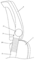
도 5 내지 도 6은 본 발명의 제2실시예에 따른 회동가능한 등받이가 구비된 의자의 회동부의 변형된 형태를 도시한 것으로서, 허리지지부(11)가 형성된 좌판(1)과, 상기 좌판(1)이 상부에 고정설치되며 지지다리(21)가 형성된 의자프레임(2)과, 상기 의자프레임(2)의 지지다리(21)에 회동부(3')에 의해 고정되어 회동가능하게 고정된 등받이(4)로 구성된 회동가능한 등받이가 구비된 의자(A')에 있어서, 상기 회동부(3')는 의자프레임(2)의 후단부에 형성된 지지다리(21)의 상단에 형성되어 등받이(4)가 회동가능하도록 상기 등받이(4)에 형성된 고정부(31')와 상기 고정부(31')가 고정되어 가압에 의해 상기 등받이(4)가 회동가능하도록 상기 지지다리(21)의 상단에 고정된 탄성스프링(32')을 포함한다.5 to 6 illustrate a modified form of a pivoting part of a chair provided with a pivotable backrest according to a second embodiment of the present invention, the
도 7 내지 도 8은 본 발명의 제3실시예에 따른 회동가능한 등받이가 구비된 의자의 회동부의 또 다른 변형된 형태를 도시한 것으로서, 허리지지부(11)가 형성된 좌판(1)과, 상기 좌판(1)이 상부에 고정설치되며 지지다리(21)가 형성된 의자프레임(2)과, 상기 의자프레임(2)에서 후단부로 연장된 등받이지지대(22)의 상단에 힌지고정부(3")에 의해 고정된 등받이(4)로 구성된 회동가능한 등받이가 구비된 의자(A")에 있어서, 상기 힌지고정부(3")는 의자에 착석한 사용자가 등받이(4)에 기대어 뒤로 젖히게 되면 등받이지지대(22)가 후방으로 약 10cm 정도 젖혀짐과 동시에 회동가능 하도록 상기 등받이지지대(22)의 상단에 형성된 회동축(221)과 상기 회동축(221)에 고정되어 회동가능하도록 등받이(4)의 후면에 형성된 힌지고정대(31")를 포함한다. 7 to 8 illustrate another modified form of the pivoting part of the chair provided with the rotatable backrest according to the third embodiment of the present invention, the
본 발명의 실시예에 따른 회동가능한 등받이가 구비된 의자는 일반 의자 제조공장에서 동일한 방법으로 반복적으로 실시하는 것이 가능하다고 할 것이므로 산업상 이용가능성이 있는 발명이라고 할 것이다.Chair with a backrest that can be rotated according to an embodiment of the present invention will be said to be able to be repeatedly carried out in the same way in a general chair manufacturing plant, the invention is industrially applicable.
1. 좌판 2. 의자프레임 3. 회동부
4. 등받이 5. 고정나사 11. 허리지지부
21. 지지다리 31. 고정본체 32. 가동본체
33. 탄성스프링1.
4.
21. Supporting
33. Elastic Spring
Claims (4)
상기 회동부(3)는 의자프레임(2)의 후단부에 형성된 지지다리(21)의 상단에 형성되어 등받이(4)가 회동가능하도록 상기 등받이(4)에 형성된 가동본체(32)가 삽입고정되는 고정본체(31)와, 상기 고정본체(31)에 삽입고정되어 회동가능하도록 탄성스프링(33)이 설치되며 등받이(4)의 양측에 형성된 가동본체(32)를 포함하는 것을 특징으로 하는 회동가능한 등받이가 구비된 의자.
A seat plate 1 having a waist support 11 formed thereon, a chair frame 2 having the seat plate 1 fixed thereto and a support leg 21 formed thereon, and a support leg 21 of the chair frame 2 formed therein. In the chair (A) provided with a rotatable backrest composed of a backrest (4) fixed to the rotatable portion (3) to be rotatable,
The pivoting part 3 is formed on the upper end of the support leg 21 formed at the rear end of the chair frame 2, and the movable body 32 formed on the backrest 4 is inserted and fixed so that the backrest 4 is rotatable. Rotating body characterized in that it comprises a fixed main body 31 and the movable body 32 is installed on both sides of the backrest 4 is provided with an elastic spring 33 is fixed to the fixed main body 31 is rotatable Chair with possible backrest.
상기 회동부(3)는, 하부에 고정지지부(311)가 형성되고 상기 고정지지부(311)의 상부에 걸림돌기(3122)가 내벽에 형성된 삽입공간(3121)이 형성되며 중앙에는 고정나사(5)가 관통되는 관통공(313)이 형성된 고정체(31)가 형성된 고정본체(31)와,
상기 고정본체(31)의 삽입공간(3121)에 삽입되도록 원통형상으로 형성되어 외면에 돌기작동홈(321)이 형성되고 상기 돌기작동홈(321)의 외측으로 스프링작동홈(322)이 형성되고 상기 스프링작동홈(322)의 내측에 탄성스프링(33)이 고정되도록 핀고정홈(3231)이 형성된 원환형의 스프링배치홈(323)이 형성되며 중앙에 상기 고정본체(31)의 관통공(313)을 통해 관통된 고정나사(5)가 고정되는 나사고정공(324)이 형성된 가동본체(42)와,
상기 가동본체(32)의 스프링배치홈(322)에 고정되도록 원환형으로 형성되며 상기 스프링배치홈(323)에 형성된 핀고정홈(3231)에 끼워져 고정되록 일단부가 절곡되어 고정핀부(331)가 형성되고 타단부는 상기 삽입공간(3121) 내벽에 형성된 걸림돌기(3122)가 걸리도록 절곡되어 가동핀부(332)가 형성된 탄성스프링(33)을 포함하는 것을 특징으로 하는 회동가능한 등받이가 구비된 의자.
The method of claim 1,
The rotating part 3 has a fixing support 311 formed at a lower portion thereof, and an insertion space 3121 having an engaging protrusion 3122 formed at an inner wall thereof at an upper portion of the fixing support 311, and having a fixing screw 5 at the center thereof. A fixed body 31 having a fixed body 31 having a through hole 313 through which
Is formed in a cylindrical shape to be inserted into the insertion space (3121) of the fixed body 31 is formed with a projection operation groove 321 on the outer surface and the spring operation groove 322 is formed to the outside of the projection operation groove 321 An annular spring arrangement groove 323 having a pin fixing groove 3321 is formed in the spring operation groove 322 so that the elastic spring 33 is fixed, and a through hole of the fixing body 31 is formed in the center of the spring operation groove 322. A movable body 42 having a screw fixing hole 324 to which the fixing screw 5 penetrated through the 313 is fixed;
It is formed in an annular shape to be fixed to the spring arrangement groove 322 of the movable body 32 and one end is bent to be fixed to be fitted into the pin fixing groove 3321 formed in the spring arrangement groove 323, the fixing pin portion 331 is The chair having a backrest, which is formed and the other end includes an elastic spring 33 which is bent to engage the engaging protrusion 3122 formed on the inner wall of the insertion space 3121 and the movable pin part 332 is formed. .
상기 회동부(3')는 의자프레임(2)의 후단부에 형성된 지지다리(21)의 상단에 형성되어 등받이(4)가 회동가능하도록 상기 등받이(4)에 형성된 고정부(31')와, 상기 고정부(31')가 고정되어 가압에 의해 상기 등받이(4)가 회동가능하도록 상기 지지다리(21)의 상단에 고정된 탄성스프링(32')을 포함하는 것을 특징으로 하는 회동가능한 등받이가 구비된 의자.
A seat plate 1 having a waist support 11 formed thereon, a chair frame 2 having the seat plate 1 fixed thereto and a support leg 21 formed thereon, and a support leg 21 of the chair frame 2 formed therein. In a chair (A ') having a rotatable backrest composed of a backrest (4) fixed by a pivoting portion (3') and rotatably fixed thereto,
The pivoting part 3 'is formed on the upper end of the support leg 21 formed at the rear end of the chair frame 2 and the fixing part 31' formed on the backrest 4 so that the backrest 4 is rotatable. And an elastic spring 32 'fixed to the upper end of the support leg 21 so that the backrest 4 is rotatable by the fixing part 31'. Equipped chair.
상기 힌지고정부(3")는 의자에 착석한 사용자가 등받이(4)에 기대어 뒤로 젖히게 되면 등받이지지대(22)가 후방으로 젖혀짐과 동시에 회동가능 하도록 상기 등받이지지대(22)의 상단에 형성된 회동축(221)과, 상기 회동축(221)에 고정되어 회동가능하도록 등받이(4)의 후면에 형성된 힌지고정대(31")를 포함하는 것을 특징으로 하는 회동가능한 등받이가 구비된 의자.A seat plate 1 having a waist support 11 formed thereon, a chair frame 2 having the seat plate 1 fixed thereto and a support leg 21 formed thereon, and a backrest extending from the chair frame 2 to a rear end thereof. In the chair (A ") with a rotatable backrest composed of a backrest (4) secured by a hinged portion (3") at the top of the support (22),
The hinge portion (3 ") is formed on the top of the back support 22 so that the user seated on the chair leans back against the back 4, the back support 22 can be flipped backwards and rotatable at the same time. And a pivoting shaft (221), and a hinged stand (31 ") formed on the back of the backrest (4) to be pivotally fixed to the pivoting shaft (221).
Priority Applications (1)
| Application Number | Priority Date | Filing Date | Title |
|---|---|---|---|
| KR1020120025076A KR101355473B1 (en) | 2012-03-12 | 2012-03-12 | A chair |
Applications Claiming Priority (1)
| Application Number | Priority Date | Filing Date | Title |
|---|---|---|---|
| KR1020120025076A KR101355473B1 (en) | 2012-03-12 | 2012-03-12 | A chair |
Related Child Applications (1)
| Application Number | Title | Priority Date | Filing Date |
|---|---|---|---|
| KR1020130154031A Division KR20140014038A (en) | 2013-12-11 | 2013-12-11 | A chair |
Publications (2)
| Publication Number | Publication Date |
|---|---|
| KR20130103988A true KR20130103988A (en) | 2013-09-25 |
| KR101355473B1 KR101355473B1 (en) | 2014-01-29 |
Family
ID=49452911
Family Applications (1)
| Application Number | Title | Priority Date | Filing Date |
|---|---|---|---|
| KR1020120025076A KR101355473B1 (en) | 2012-03-12 | 2012-03-12 | A chair |
Country Status (1)
| Country | Link |
|---|---|
| KR (1) | KR101355473B1 (en) |
Cited By (3)
| Publication number | Priority date | Publication date | Assignee | Title |
|---|---|---|---|---|
| KR101503490B1 (en) * | 2013-11-14 | 2015-03-18 | (주)디에스피 | Rotating parts for chairs back |
| KR20200103968A (en) * | 2019-02-26 | 2020-09-03 | (주)지앤엘리사이클링 | Tilling cushion structure of back sheet in Chair |
| KR102640132B1 (en) * | 2023-11-17 | 2024-02-22 | 김현곤 | Apparatus for tilting the backrest and chair with the same |
Families Citing this family (6)
| Publication number | Priority date | Publication date | Assignee | Title |
|---|---|---|---|---|
| KR101490435B1 (en) | 2014-10-29 | 2015-02-06 | (주)디에스피 | The chair with adjustable backrest angle |
| KR101495325B1 (en) * | 2014-10-29 | 2015-03-03 | (주)디에스피 | A structure to control angle of the back of chair |
| KR101635495B1 (en) * | 2016-02-23 | 2016-07-01 | 주식회사 다원체어스 | Chair having tiltable backrest |
| KR101635449B1 (en) * | 2016-03-14 | 2016-07-01 | 주식회사 다원체어스 | Locking tilt mechanism for back of chair |
| KR102172990B1 (en) | 2018-08-30 | 2020-11-02 | 정윤산 | Chair with increased seat and back |
| KR102158287B1 (en) * | 2020-04-27 | 2020-09-21 | (주)씨텍코리아 | chair |
Family Cites Families (4)
| Publication number | Priority date | Publication date | Assignee | Title |
|---|---|---|---|---|
| KR20090074288A (en) * | 2008-01-02 | 2009-07-07 | 노진호 | The chair |
| US8939508B2 (en) * | 2008-05-13 | 2015-01-27 | Chokchai Charoenapornwatana | Chairs with flexible spring backrest |
| KR101062059B1 (en) * | 2009-03-24 | 2011-09-02 | 김현곤 | Folding chair with adjustable backrest angle |
| TWM370350U (en) * | 2009-06-05 | 2009-12-11 | Wen-Shan Ko | Chairs with predetermined pressure structure |
-
2012
- 2012-03-12 KR KR1020120025076A patent/KR101355473B1/en active IP Right Grant
Cited By (3)
| Publication number | Priority date | Publication date | Assignee | Title |
|---|---|---|---|---|
| KR101503490B1 (en) * | 2013-11-14 | 2015-03-18 | (주)디에스피 | Rotating parts for chairs back |
| KR20200103968A (en) * | 2019-02-26 | 2020-09-03 | (주)지앤엘리사이클링 | Tilling cushion structure of back sheet in Chair |
| KR102640132B1 (en) * | 2023-11-17 | 2024-02-22 | 김현곤 | Apparatus for tilting the backrest and chair with the same |
Also Published As
| Publication number | Publication date |
|---|---|
| KR101355473B1 (en) | 2014-01-29 |
Similar Documents
| Publication | Publication Date | Title |
|---|---|---|
| KR101355473B1 (en) | A chair | |
| WO2006033339A1 (en) | Back rest tilting device in reclining chair | |
| JP2009509592A (en) | Chair | |
| JP2007268118A (en) | Stool rockable in seat part | |
| KR101009490B1 (en) | A chair comprised seat plate moving structure | |
| KR20120134233A (en) | Adjusting apparatus for chair arm rest | |
| KR101538342B1 (en) | The chair | |
| JP2006296960A (en) | Chair having massage function | |
| JP3177652U (en) | Chair seat guide device | |
| KR100908737B1 (en) | A chair | |
| KR101461809B1 (en) | A chair | |
| KR101733981B1 (en) | Chair with adjustable headrest | |
| KR20140014038A (en) | A chair | |
| JP2020058759A (en) | Chair | |
| KR200380543Y1 (en) | Chair of sitting-down type | |
| KR101009491B1 (en) | A chair have a back seat tilting structure | |
| KR101591947B1 (en) | Chair of up-down and revolution a board back | |
| JP3191527U (en) | Arm holder | |
| KR101009488B1 (en) | A chair have a back seat assembling structure | |
| KR100588979B1 (en) | A chair | |
| JP4629395B2 (en) | Tilting device for backrest in reclining chair | |
| JP7382187B2 (en) | Chair | |
| KR101062216B1 (en) | chair | |
| JP2014004322A (en) | Rocking chair | |
| KR200361365Y1 (en) | chair |
Legal Events
| Date | Code | Title | Description |
|---|---|---|---|
| A201 | Request for examination | ||
| E902 | Notification of reason for refusal | ||
| AMND | Amendment | ||
| E601 | Decision to refuse application | ||
| X091 | Application refused [patent] | ||
| A107 | Divisional application of patent | ||
| AMND | Amendment | ||
| X701 | Decision to grant (after re-examination) | ||
| GRNT | Written decision to grant | ||
| FPAY | Annual fee payment |
Payment date: 20161228 Year of fee payment: 4 |
|
| FPAY | Annual fee payment |
Payment date: 20191209 Year of fee payment: 7 |