KR20130103796A - Method and device for removing a sample from a coil - Google Patents
Method and device for removing a sample from a coil Download PDFInfo
- Publication number
- KR20130103796A KR20130103796A KR1020137019214A KR20137019214A KR20130103796A KR 20130103796 A KR20130103796 A KR 20130103796A KR 1020137019214 A KR1020137019214 A KR 1020137019214A KR 20137019214 A KR20137019214 A KR 20137019214A KR 20130103796 A KR20130103796 A KR 20130103796A
- Authority
- KR
- South Korea
- Prior art keywords
- coil
- sample
- sampling
- roller unit
- strip tip
- Prior art date
Links
Images


Classifications
-
- B—PERFORMING OPERATIONS; TRANSPORTING
- B21—MECHANICAL METAL-WORKING WITHOUT ESSENTIALLY REMOVING MATERIAL; PUNCHING METAL
- B21C—MANUFACTURE OF METAL SHEETS, WIRE, RODS, TUBES OR PROFILES, OTHERWISE THAN BY ROLLING; AUXILIARY OPERATIONS USED IN CONNECTION WITH METAL-WORKING WITHOUT ESSENTIALLY REMOVING MATERIAL
- B21C47/00—Winding-up, coiling or winding-off metal wire, metal band or other flexible metal material characterised by features relevant to metal processing only
- B21C47/32—Tongs or gripping means specially adapted for reeling operations
-
- G—PHYSICS
- G01—MEASURING; TESTING
- G01N—INVESTIGATING OR ANALYSING MATERIALS BY DETERMINING THEIR CHEMICAL OR PHYSICAL PROPERTIES
- G01N1/00—Sampling; Preparing specimens for investigation
- G01N1/02—Devices for withdrawing samples
- G01N1/04—Devices for withdrawing samples in the solid state, e.g. by cutting
-
- B—PERFORMING OPERATIONS; TRANSPORTING
- B21—MECHANICAL METAL-WORKING WITHOUT ESSENTIALLY REMOVING MATERIAL; PUNCHING METAL
- B21C—MANUFACTURE OF METAL SHEETS, WIRE, RODS, TUBES OR PROFILES, OTHERWISE THAN BY ROLLING; AUXILIARY OPERATIONS USED IN CONNECTION WITH METAL-WORKING WITHOUT ESSENTIALLY REMOVING MATERIAL
- B21C47/00—Winding-up, coiling or winding-off metal wire, metal band or other flexible metal material characterised by features relevant to metal processing only
- B21C47/16—Unwinding or uncoiling
- B21C47/18—Unwinding or uncoiling from reels or drums
-
- B—PERFORMING OPERATIONS; TRANSPORTING
- B21—MECHANICAL METAL-WORKING WITHOUT ESSENTIALLY REMOVING MATERIAL; PUNCHING METAL
- B21C—MANUFACTURE OF METAL SHEETS, WIRE, RODS, TUBES OR PROFILES, OTHERWISE THAN BY ROLLING; AUXILIARY OPERATIONS USED IN CONNECTION WITH METAL-WORKING WITHOUT ESSENTIALLY REMOVING MATERIAL
- B21C47/00—Winding-up, coiling or winding-off metal wire, metal band or other flexible metal material characterised by features relevant to metal processing only
- B21C47/32—Tongs or gripping means specially adapted for reeling operations
- B21C47/326—Devices for pressing the end of the material being wound against the cylindrical wall of the reel or bobbin
-
- B—PERFORMING OPERATIONS; TRANSPORTING
- B21—MECHANICAL METAL-WORKING WITHOUT ESSENTIALLY REMOVING MATERIAL; PUNCHING METAL
- B21C—MANUFACTURE OF METAL SHEETS, WIRE, RODS, TUBES OR PROFILES, OTHERWISE THAN BY ROLLING; AUXILIARY OPERATIONS USED IN CONNECTION WITH METAL-WORKING WITHOUT ESSENTIALLY REMOVING MATERIAL
- B21C51/00—Measuring, gauging, indicating, counting, or marking devices specially adapted for use in the production or manipulation of material in accordance with subclasses B21B - B21F
-
- B—PERFORMING OPERATIONS; TRANSPORTING
- B65—CONVEYING; PACKING; STORING; HANDLING THIN OR FILAMENTARY MATERIAL
- B65B—MACHINES, APPARATUS OR DEVICES FOR, OR METHODS OF, PACKAGING ARTICLES OR MATERIALS; UNPACKING
- B65B27/00—Bundling particular articles presenting special problems using string, wire, or narrow tape or band; Baling fibrous material, e.g. peat, not otherwise provided for
- B65B27/06—Bundling coils of wire or like annular objects
-
- B—PERFORMING OPERATIONS; TRANSPORTING
- B65—CONVEYING; PACKING; STORING; HANDLING THIN OR FILAMENTARY MATERIAL
- B65B—MACHINES, APPARATUS OR DEVICES FOR, OR METHODS OF, PACKAGING ARTICLES OR MATERIALS; UNPACKING
- B65B69/00—Unpacking of articles or materials, not otherwise provided for
Landscapes
- Engineering & Computer Science (AREA)
- Mechanical Engineering (AREA)
- General Health & Medical Sciences (AREA)
- General Physics & Mathematics (AREA)
- Life Sciences & Earth Sciences (AREA)
- Chemical & Material Sciences (AREA)
- Analytical Chemistry (AREA)
- Biochemistry (AREA)
- Physics & Mathematics (AREA)
- Health & Medical Sciences (AREA)
- Immunology (AREA)
- Pathology (AREA)
- Sampling And Sample Adjustment (AREA)
- Basic Packing Technique (AREA)
- Winding, Rewinding, Material Storage Devices (AREA)
- Unwinding Of Filamentary Materials (AREA)
Abstract
본 출원은 코일(2)에서 시료(24)를 채취하기 위한 시료 채취 장치(1)에 관한 것이며, 상기 시료 채취 장치는 시료 채취 동안 코일(2)을 지지하기 위한 하나 이상의 베이스 롤러 유닛(30, 32)과, 코일(2)의 외주면을 압착할 수 있는 하나 이상의 압착 롤러 유닛(40, 42)과, 하나 이상의 베이스 롤러 유닛(30, 32) 상에서 지지되는 코일(2)을 결속하기 위한 하나 이상의 밴드 결속 장치(60)를 포함한다. 또한, 본 출원은 코일(2)에서 시료(24)를 채취하기 위한 시료 채취 장치(1')에 관한 것이며, 상기 시료 채취 장치(1')는 바로 아래 위치하는 층(22)으로부터 코일(2)의 재료 포착부(20)를 편향시키기 위한 편향 장치(70)를 포함하며, 이 편향 장치(70)는 코일(2)의 스트립 선단(20)이 바로 아래 위치하는 층(22)으로부터 탄성으로만 편향될 수 있다. 또한, 본 출원은 상응하는 방법에도 관한 것이다.The present application relates to a sampling device (1) for taking a sample (24) from the coil (2), said sampling device for at least one base roller unit (30) for supporting the coil (2) during sampling; 32, one or more crimping roller units 40, 42 capable of crimping the outer circumferential surface of the coil 2, and one or more for engaging the coil 2 supported on the one or more base roller units 30, 32; And a band binding device 60. The present application also relates to a sampling device 1 ′ for collecting a sample 24 from the coil 2, wherein the sampling device 1 ′ is a coil 2 from a layer 22 located directly below. A deflecting device 70 for deflecting the material trapping portion 20 of the coils, which is elastically elastic from the layer 22 in which the strip tip 20 of the coil 2 is located directly below. Only can be deflected. The present application also relates to a corresponding method.

Description
본 발명은, 코일에서, 특히 금속 스트립 코일에서 시료를 채취하기 위한 장치 및 그 방법에 관한 것이다.The present invention relates to an apparatus and a method for sampling a coil, in particular a metal strip coil.
압연기에서, 압연된 금속 스트립을 제조할 경우, 보통은 압연 공정의 종료 후에 압연된 금속 스트립을 코일로 권취한다. 코일 상에는, 압연된 금속 스트립의 섹션이면서 길이가 길고 절단되지 않은 상기 섹션이 그에 상응하게 위치한다. 이 경우, 금속 스트립 코일의 중량은 전형적으로 최대 40톤에 이르며, 그럼으로써 코일의 안전한 취급을 위해 그에 상응하는 육중한 장치들이 필요하다.In a rolling mill, when producing a rolled metal strip, the rolled metal strip is usually wound into a coil after the end of the rolling process. On the coil, the section of the rolled metal strip, which is long and uncut, is correspondingly located. In this case, the weight of the metal strip coil is typically up to 40 tonnes, whereby corresponding heavy devices are required for the safe handling of the coil.
각각 압연된 스트립들의 제조 품질을 검사하고 보장할 수 있도록 하기 위해, 각각의 코일들로부터 시료들을 채취할 필요가 있다. 이 경우, 시료들은 전형적으로 코일의 외주면 상에 위치하는 스트립 선단으로부터 채취된다. 특히, 코일 상에 권취된 재료의 시료를 얻기 위해, 스트립 선단 및/또는 스트립 말단의 한 조각이 절단된다. 그 다음 시료들은 독립된 검사부로 공급된다.In order to be able to inspect and ensure the manufacturing quality of each rolled strip, it is necessary to take samples from the respective coils. In this case, samples are typically taken from the strip tip located on the outer circumferential surface of the coil. In particular, to obtain a sample of the material wound on the coil, one piece of strip tip and / or strip end is cut. The samples are then fed to an independent test unit.
바람직하게는, 이처럼, 실질적인 시료 채취 외에도, 스트립 선단 및/또는 스트립 말단의 불량 부분 제거(purging)도 달성될 수 있다.Preferably, in addition to the actual sampling as such, purging of the strip tip and / or strip end can also be achieved.
각각의 코일들은, 상응하는 권취 장치 또는 권취기로부터 인출된 후에 이송 시 튀어오르는 것이 아니라 원래 권취된 형태를 유지하도록 밴드(band)로 결속된다. 상기 밴드는 통상적으로, 이송 시 작용하는 힘에 반작용할 수 있도록 하기 위해, 강철 밴드나 만곡된 평강의 형태로 형성된다.Each of the coils is bound in a band so as to retain their originally wound form rather than spring up upon transfer after being withdrawn from the corresponding winding device or winder. The bands are typically formed in the form of steel bands or curved flat steels in order to be able to react to the forces acting upon transfer.
한편, 상기 결속된 코일에서 시료 채취를 실행할 수 있도록 하기 위해, 밴드 결속 재료가 분리되고, 스트립 선단이 코일에서 권출되고, 권출된 스트립 선단의 한 조각이 시료로서 절단되고, 스트립 선단은 다시 코일로 재권취되며, 이후 추가의 재이송 시 코일의 바운싱을 방지하도록 하기 위해 새 밴드가 코일의 둘레에 장착되어야만 한다.On the other hand, in order to be able to perform sampling on the bound coil, the band binding material is separated, the strip tip is unwound from the coil, one piece of the unwound strip tip is cut as a sample, and the strip tip is returned to the coil. After rewinding, a new band must be fitted around the coil to prevent the coil from bouncing on further retransmission.
코일의 상기 재결속을 달성하도록 하기 위해, 코일들은 복잡하게 수작업으로 결속되거나, 또는 코일들은 시료 채취 후에 독립된 결속 스테이션(binding station)으로 이송된다.In order to achieve the above rebound of the coils, the coils are complicatedly bound manually or the coils are transferred to a separate binding station after sampling.
코일의 권출 시, 스트립 선단은, 적어도 재료 및 재료 두께가 그에 상응하는 경우, 스트립 선단의 바람직한 절단 위치를 확보하기 위해 소성 변형된다. 후속하는 스트립 선단의 재권취 시에 스트립은 소성 굽힘 방식으로 다시 코일 형태로 휘어진다.Upon unwinding of the coil, the strip tip is plastically deformed to ensure the desired cutting position of the strip tip, at least when the material and material thickness are corresponding thereto. Upon subsequent rewinding of the strip tip, the strip is again bent in coil form in a plastic bending manner.
시료 채취와 관련하여, EP 1 888 284 B1은 코일로 권취된 압연 스트립에서 말단들을 절단 폐기하거나 시료편을 절단하기 위한 장치 및 방법을 제안하고 있으며, 상기 장치는 전단기와, 제1 및 제2 베이스 롤러와, 하나 이상의 위치 가변형 압착 롤러를 포함한다.With regard to sampling,
DE 10 2007 017 383 A1로부터는 코일을 결속하기 위한 장치가 공지되었다. 상기 장치의 경우, 코일은 회전 구동되는 맨드릴 상에 위치되고, 코일 외주에 상응하게 사전 제조된 길이로 사전 만곡된 평강 밴드(flat steel band)를 코일로 공급하는 벤딩 스테이션(bending station)이 제공된다. 상기 평강 밴드는 하나 이상의 압착 롤러에 의해 코일의 둘레를 따라 안내될 수 있고 평강 밴드의 말단들은 서로 결합될 수 있다.From DE 10 2007 017 383 A1 a device for binding a coil is known. In the case of the device, the coil is located on a rotationally driven mandrel and a bending station is provided for supplying the coil with flat steel bands precured to a prefabricated length corresponding to the coil periphery. . The flat band can be guided along the circumference of the coil by one or more pressing rollers and the ends of the flat band can be joined together.
또한, 종래 기술로부터는, 시료 채취를 위해, 코일의 스트립 선단을 계속해서 굽히며, 그리고 스트립 선단이 각각의 절단 장치로 안내되는 방식으로 상기 스트립 선단을 편향시키는 점도 공지되었다. 상기 장치는 예컨대 WO 2009/047395 A1로부터 공지되었다.It is also known from the prior art to continuously bend the strip tip of the coil for sampling and to deflect the strip tip in such a way that the strip tip is guided to the respective cutting device. Such a device is known from WO 2009/047395 A1, for example.
이처럼 소성 변형된 스트립 선단은 후속하여 다시 코일로 형성되어야 한다.This plastically deformed strip tip must subsequently be formed into a coil again.
본 발명의 과제는 그에 상응하게 코일에서, 특히 금속 스트립 코일에서 효율적인 시료 채취를 위한 장치 및 그 방법을 제공하는 것에 있다.It is therefore an object of the present invention to provide an apparatus and method for efficient sampling in coils, in particular in metal strip coils.
상기 과제는 청구항 제1항의 특징들을 포함하는 장치를 통해 해결된다. 바람직한 구현예들은 종속항들에서 제시된다.This problem is solved through an apparatus comprising the features of
그에 상응하게, 코일에서 시료를 채취하기 위한 장치는, 시료 채취 동안 코일을 지지하기 위한 하나 이상의 베이스 롤러 유닛과, 코일의 외주면을 압착할 수 있는 하나 이상의 압착 롤러 유닛과, 하나 이상의 베이스 롤러 유닛 상에서 지지되는 코일을 결속하기 위한 하나 이상의 밴드 결속 장치를 포함한다.Correspondingly, an apparatus for taking a sample from a coil includes at least one base roller unit for supporting the coil during sampling, at least one press roller unit capable of pressing the outer circumferential surface of the coil, and at least one base roller unit. One or more band binding devices for binding the supported coils.
압착 롤러 유닛에 의해, 코일은 시료 채취 시에, 그리고 후속하는 결속 시에 튀어오르지 않는 점이 달성될 수 있다. 이처럼, 작업 중인 직원을 위한 안전은 증가되고 코일의 판매 품질은 향상된다. 그 다음, 압착 롤러 유닛에 의해 파지되고 그에 상응하게 시료 채취 후에도 튀어오르지 않는 코일은, 시료 채취 후에 밴드 결속 유닛에 의해 곧바로 다시 밴드로 결속될 수 있다. 그에 상응하게, 복잡한 수동 재결속 또는 독립된 결속 스테이션으로의 이동은 배제할 수 있으며, 코일은 시료 채취 및 결속 후 그 즉시 다시 판매 완료 상태가 된다.By means of the compacting roller unit, it can be achieved that the coil does not bounce at the time of sampling and at the subsequent binding. As such, safety for the working staff is increased and the coil's sales quality is improved. Then, the coil grasped by the pressing roller unit and correspondingly does not spring up even after sampling can be bound back to the band immediately by the band binding unit after sampling. Correspondingly, complicated manual rebinding or moving to an independent binding station can be ruled out, and the coils are immediately ready for resale after sampling and binding.
달리 말하면, 명시된 장치를 통해, 효율적인 시료 채취와 이에 후속하여 우수한 제품 품질이 달성될 수 있는데, 그 이유는 코일의 개방, 다시 말하면 밴드의 제거, 시료 채취 및 후속하는 코일의 재결속이 단일의 장치의 내부에서 실행될 수 있기 때문이다. 시료 채취 시 코일의 바운싱은 압착 롤러 유닛에 의해 방지될 수 있으며, 그럼으로써 코일의 권취 품질은 시료 채취를 통해 저하되지도 않는다.In other words, with the specified device, efficient sampling and subsequent good product quality can be achieved, because the opening of the coil, i.e. the removal of the band, the sampling and subsequent recoupling of the coil can be achieved by a single device. This can be done internally. The bounce of the coil during sampling can be prevented by the press roller unit, so that the coil's winding quality is not degraded through sampling.
시료 채취 후에 코일의 효율적인 결속을 달성할 수 있도록 하기 위해, 베이스 롤러 유닛의 롤러들 및/또는 압착 롤러 유닛의 롤러들은 밴드 결속 재료를 통과시키고, 그리고/또는 밴드 결속 채널을 형성하기 위한 홈부들(recess)을 포함한다In order to be able to achieve an efficient binding of the coil after sampling, the rollers of the base roller unit and / or the rollers of the compacting roller unit pass through the band binding material and / or grooves for forming the band binding channel ( I include a recess
전술한 홈부들에 대체되거나 보충되는 방식으로, 베이스 롤러 유닛의 롤러들 및/또는 압착 롤러 유닛의 롤러들은 바람직하게는 각각 2개 이상의 롤러 유닛을 포함하며, 개별 롤러 부재들 사이에서 밴드 결속 재료가 통과될 수 있고, 그리고/또는 밴드 결속 채널이 형성된다.In a manner replaced or supplemented with the above-mentioned grooves, the rollers of the base roller unit and / or the rollers of the pressing roller unit preferably each comprise two or more roller units, and a band binding material is formed between the individual roller members. Can be passed and / or a band binding channel is formed.
훨씬 더 확실한 코일의 취급은 코일의 외주면을 압착할 수 있는 하나 이상의 제2 압착 롤러 유닛을 제공하는 것을 통해 달성된다. 바람직하게는, 다양한 코일 지름들에 적합하게 장치를 조정하도록 하기 위해, 하나 이상의 고정형 베이스 롤러 유닛과 하나 이상의 이동형 베이스 롤러 유닛도 제공된다. 바람직하게는, 각각의 베이스 롤러 유닛들과 각각의 압착 롤러 유닛들은, 모든 방향으로부터 코일을 확실하게 둘러싸도록 하기 위해, 약 90°만큼 상호 간에 오프셋 되어 배치된다.Even more certain handling of the coil is achieved through the provision of one or more second pressing roller units capable of pressing the outer circumferential surface of the coil. Preferably, one or more stationary base roller units and one or more movable base roller units are also provided in order to adjust the device for various coil diameters. Preferably, each of the base roller units and each of the pressing roller units are arranged offset from each other by about 90 ° so as to reliably surround the coil from all directions.
시료 채취를 위해, 바람직하게는, 코일의 스트립 선단에서 시료를 채취하기 위한 시료 채취 스테이션도 제공된다.For sampling, a sampling station is also preferably provided for sampling at the tip of the strip of the coil.
바람직하게는, 바로 아래 위치하는 층으로부터 코일의 스트립 선단을 편향시키기 위한 하나 이상의 편향 장치가 제공되며, 편향 장치는, 코일의 스트립 선단이 바로 아래 위치하는 층으로부터 탄성으로만 편향될 수 있도록 형성된다. 이처럼, 코일 상으로 스트립 선단을 재권취할 때 다시 반복되는 소성 변형도 필요하게 하는 시료 채취 시 소성 변형은 방지되는 점이 달성될 수 있다.Preferably, at least one deflection device is provided for deflecting the strip leading end of the coil from the layer located directly below it, wherein the deflection device is formed such that the strip leading end of the coil can only be deflected elastically from the layer directly below it. . As such, it can be achieved that plastic deformation is avoided during sampling, which also requires repeated plastic deformation when the coil is rewound onto the coil.
또한, 본원의 과제는, 청구항 제8항의 특징들을 갖는 장치를 통해 해결된다. 바람직한 구현예들은 종속항들에서 제시된다.The subject matter is also solved through an apparatus having the features of claim 8. Preferred embodiments are presented in the dependent claims.
그에 상응하게, 코일에서 시료를 채취하기 위한 장치는 바로 아래 위치하는 층으로부터 코일의 재료 포착부(material catch)를 편향시키기 위한 편향 장치를 포함하며, 편향 장치는, 코일의 스트립 선단이 바로 아래 위치하는 층으로부터 탄성으로만 편향될 수 있도록 형성된다.Correspondingly, the device for sampling the coil comprises a deflection device for deflecting the material catch of the coil from the layer located directly below, wherein the deflection device is positioned directly below the strip tip of the coil. It is formed so that it can only deflect elastically from the layer.
상기 사항은, 특히 코일로부터 권출된 금속 스트립의 소성 변형이 개시되지 않는다는 점도 의미한다. 그럼으로써 스트립 선단이 시료 채취 후에 바로 아래 위치하는 코일의 층에 다시 완전하게 안착되며, 이때 추가 변형 단계들은 필요하지 않게 되는 점이 달성된다. 그럼으로써 한편으로 스트립 품질은 저하되지 않고 다른 한편으로는 시료 채취 과정과 특히 후속하는 결속 과정이 분명하게 단순화될 수 있다.The above also means that plastic deformation of the metal strip unwound from the coil is not disclosed. This achieves the fact that the strip tip rests completely again in the layer of coil which lies directly below the sample after sampling, with no further deformation steps required. The strip quality on the one hand is thus not deteriorated and on the other hand the sampling process and in particular the subsequent binding process can be clearly simplified.
바람직하게는, 편향 장치는, 코일의 스트립 선단의 탄성 변형만이 개시되도록 상기 스트립 선단이 힘에 의해 바로 아래 위치하는 층으로부터 편향될 수 있도록 기하 구조, 배향 및/또는 위치 결정을 나타내는 편향 부재를 포함한다. 이 경우, 편향 부재는 바람직하게는 예각을 갖는 바람직하게는 쐐기의 형태로 형성된다.Preferably, the deflection device comprises a deflection member that exhibits a geometry, orientation and / or positioning such that the strip tip can be deflected from the layer located directly beneath by force such that only the elastic deformation of the strip tip of the coil is initiated. Include. In this case, the deflection member is preferably formed in the form of a wedge, preferably having an acute angle.
상응하는 탄성 편향을 달성하도록 하기 위해, 편향 장치는 코일의 외주면에 바람직하게는 실질적으로 접선으로 공급될 수 있다.In order to achieve a corresponding elastic deflection, the deflection device can preferably be supplied substantially tangentially to the outer circumferential surface of the coil.
시료 채취를 위해, 코일에서 시료를 절단하기 위한 절단 장치가 제공될 수 있고, 절단 장치는 바람직하게는 바로 아래 위치하는 코일의 층에 대해 실질적으로 수직 방향으로 스트립 선단에 작용한다. 이처럼, 시료 채취를 위한 스트립의 소성 변형은 방지될 수 있다. 특히 편향 장치는 바람직하게는, 상부에서 시료의 실질적인 절단이 실행될 수 있으면서 바로 아래 위치하는 코일의 층은 손상되지 않게 하는 전단기, 앤빌(anvil) 또는 절단 레일(cutting rail)을 포함한다.For sampling, a cutting device may be provided for cutting the sample in the coil, which preferably acts on the strip tip in a direction substantially perpendicular to the layer of coil located directly below. As such, plastic deformation of the strip for sampling can be prevented. In particular, the deflection device preferably comprises a shear, anvil or cutting rail which allows the substantial cutting of the sample at the top to be carried out while the layer of the coil just below it is not damaged.
코일의 효율적인 가공을 가능하게 하기 위해, 바람직하게는 코일을 결속하기 위한 밴드 결속 장치가 제공되며, 그럼으로써 코일은 스트립 선단의 재권취 후에 후속하는 결속을 위해 이동되지 않아도 된다.In order to enable efficient processing of the coil, a band binding device is preferably provided for binding the coil so that the coil does not have to be moved for subsequent binding after rewinding of the strip tip.
예컨대 전방의 스트립 테두리를 추적하기 위한 센서의 형태, 또는 편향 장치의 위치에 상대적으로 이루어진 코일 회전을 추적하기 위한 센서의 형태로 직접 또는 간접적으로 측정하는 센서들은, 바람직하게는 정의된 시료 채취와, 바로 아래 위치하는 코일의 층으로부터 스트립 선단의 목표하는 적은 편향을 제어하고 모니터링하기 위해 제공된다.Sensors measuring directly or indirectly, for example in the form of a sensor for tracking the front strip rim, or in the form of a sensor for tracking the coil rotation made relative to the position of the deflection device, preferably have a defined sampling, It is provided for controlling and monitoring the desired small deflection of the strip tip from the layer of coil located just below it.
또한, 앞서 설정한 과제는 청구항 제15항 및 제16항에 따르는 방법을 통해 해결된다.In addition, the problem set out above is solved through the method according to claim 15 and 16.
그에 상응하게, 코일에서 시료를 채취하기 위한 방법은, 하나 이상의 베이스 롤러 유닛 상에 코일을 지지하는 단계와, 하나 이상의 압착 롤러 유닛으로 코일의 외주면을 압착하는 단계와, 시료를 채취하는 단계와, 밴드 결속 장치를 이용하여, 하나 이상의 베이스 롤러 유닛 상에서 지지되는 코일을 결속하는 단계를 포함한다.Correspondingly, a method for taking a sample from a coil includes supporting a coil on at least one base roller unit, pressing the outer circumferential surface of the coil with at least one pressing roller unit, taking a sample, Using a band binding device, binding the coil supported on the one or more base roller units.
또한, 본원의 방법은, 대체되거나 보충되는 방식으로, 스트립 선단의 탄성 변형만이 개시되는 방식으로 바로 아래 위치하는 층으로부터 코일의 스트립 선단을 편향시키는 단계와, 탄성 편향된 코일의 스트립 선단에서 시료를 채취하는 단계와, 바로 아래 위치하는 층에 스트립 선단을 안착시키는 단계도 포함한다.In addition, the method herein comprises deflecting the strip tip of the coil from a layer located directly below it in such a way that only the elastic deformation of the strip tip is initiated, in an alternative or supplementary manner, and the sample at the strip tip of the elastically deflected coil. Harvesting and seating the tip of the strip on the layer located beneath it.
탄성 변형만을 제공하기 위한 최대 적용되는 힘은 계산되고, 실험을 기반으로 산출되고, 그리고/또는 경험치를 기반으로 결정된다.The maximum applied force to provide only elastic deformation is calculated, calculated based on experiments, and / or determined based on experience.
본 발명은 코일에서 시료를 채취하기 위한 장치 및 그 방법에 관한 것으로서, 본 발명에 의하여, 특히 금속 스트립 코일에서 효율적으로 시료를 채취하는 것이 가능하다. The present invention relates to an apparatus and a method for collecting a sample from a coil, and according to the present invention, in particular, it is possible to efficiently sample from a metal strip coil.
본 출원의 바람직한 추가 실시예들 및 관점들은 도들에 대한 하기의 설명을 통해 더욱 상세하게 설명된다.
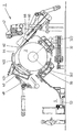
도 1은 본 출원에 따라서 코일에서 시료 채취를 위한 장치를 도시한 개략적 측면도이다.
도 2는 제2 작동 상태에서 도 1에 따른 장치를 도시한 개략적 측면도이다.
도 3은 지속적인 소성 변형의 조건에서 코일의 스트립 선단이 편향된 상태를 도시한 개략도이다.
도 4는 코일 상에 신규 스트립 선단을 안착한 후에 남아 있는 소성 변형 상태를 도시한 개략도이다.
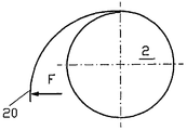
도 5는 탄성 변형만이 개시된 조건에서 스트립 선단이 편향된 상태를 도시한 개략도이다.
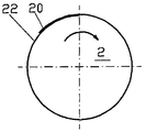
도 6은 소성 변형만이 개시된 후에 신규 스트립 선단이 복귀된 상태를 도시한 개략도이다.
도 7은 시료 채취를 위한 추가 장치를 도시한 개략도이다.Further preferred embodiments and aspects of the present application are described in more detail through the following description of the figures.
1 is a schematic side view illustrating an apparatus for sampling in a coil in accordance with the present application.
Figure 2 shows a schematic side view of the device according to figure 1 in a second operating state;
3 is a schematic diagram showing a state in which the strip tip of the coil is deflected under the condition of continuous plastic deformation.
4 is a schematic diagram showing the plastic deformation state remaining after seating a new strip tip on the coil.
5 is a schematic view showing a state in which the tip of the strip is deflected under only the condition of the elastic deformation.
6 is a schematic diagram showing a state in which a new strip tip is returned after only plastic deformation is started.
7 is a schematic diagram illustrating an additional device for sampling.
하기에는, 바람직한 실시예들이 도들에 따라 설명된다. 여기서 동일하거나 유사한 부재들은 동일한 도면 부호로 표시되며, 상기 부재들의 반복 설명은 중복을 피하기 위해 부분적으로 생략된다.In the following, preferred embodiments are described according to the figures. The same or similar members are denoted by the same reference numerals, and the repeated description of the members is partially omitted to avoid duplication.
도 1에는, 코일(2), 특히 금속 스트립 코일에서 시료를 채취하기 위한 장치(1)가 도시되어 있다. 코일에서 시료를 채취하기 위해, 코일의 원래 결속을 해제해야 하며, 그럼으로써 코일의 스트립 선단은, 이후 시료로서 스트립 선단의 일부분을 절단하기 위해, 코일로부터 인출될 수 있게 된다. 스트립 선단에서 시료의 절단 후에, 신규 선단이 된 스트립 선단은 다시 코일에 안착되어야 하며(다시 말해 다시 권취되어야 하며), 그리고 코일은 다시 결속되어야 한다.1 shows an
도 1에는, 2개의 베이스 롤러 유닛(30, 32) 상에서 지지되는 코일(2)이 도시되어 있다. 베이스 롤러 유닛들은, 코일(2)의 각각 최외측 권취층[다시 말해 코일(2)의 외주면]과 직접적으로 접촉하는 롤러(34)들을 각각 포함하며, 이들 롤러 상에서 코일(2)은 자체의 권취 축을 중심으로 회전 가능하게 지지된다.1 shows a
일측의 베이스 롤러 유닛(30)은 고정형으로 형성되고, 제2 베이스 롤러 유닛(32)은, 다양한 지름들을 갖는 코일들을 완벽하게 수용할 수 있도록 하기 위해, 이동 장치(36)에 의해 위치 조정될 수 있다. 그러므로 이동형 베이스 롤러 유닛(32)을 통해, 장치(1)의 내부에서 기하 비율은 코일(2)의 각각의 지름에 상응하게 실질적으로 동일하게 형성될 수 있다.The
베이스 롤러 유닛(30, 32)들에 대해서 코일(2)과 관련하여 약 90°만큼 변위되어 배치되는 제1 압착 롤러 유닛(40)과 제2 압착 롤러 유닛(42)이 제공된다. 압착 롤러 유닛들은 마찬가지로 각각 2개의 롤러(44)를 포함하고, 이들 롤러는 각각 코일(2)의 최외측 권취층과 직접적으로 접촉한다. 압착 롤러 유닛(40, 42)들은, 예컨대 유압 실린더에 의해 형성될 수 있는 각각의 이동 장치(46)들에 의해, 각각 코일(2)의 지름에 따라서, 코일(2)의 각각의 바깥쪽 권취층에 안착될 수 있으며, 그리고 코일의 간편한 수용 및 상향 인출을 가능하게 하기 위해, 코일로부터 완전하게 상승될 수 있다.A first
압착 롤러 유닛(40, 42)들은, 시료를 채취할 수 있도록 하기 위해, 코일(2)의 결속이 해제될 때 코일의 권취층들을 파지 또는 고정하기 위해 이용된다. 이처럼, 코일(2)이 튀어오르고 권취층들이 느슨해질 수 있는 점은 방지될 수 있다.The
베이스 롤러 유닛(30, 32)들 및 압착 롤러 유닛(40, 42)들은 바람직하게는, 시료 채취를 위해 스트립 선단을 인출할 때 개별 코일 권취층들과 특히 코일의 최외측 권취층의 균일한 압착을 달성하기 위해, 코일(2)의 둘레를 따라 균일한 이격 간격 또는 균일한 회전 각도로 배치된다.The
실질적인 시료 채취를 위해, 코일(2)의 스트립 선단은 시료 채취 스테이션(5)의 방향으로 인출되고, 인출된 위치에서 도 1에는 미도시된 절단 장치에 의해 절단되며, 이후 절단된 시료는 시료 배출 장치(50)를 통해 상응하는 분석 스테이션으로 공급된다.For substantial sampling, the strip tip of the
시료가 채취된 후에, 스트립 말단은, 예컨대 코일(2)이 권출 방향의 반대 방향으로 회전됨으로써, 코일(2) 상으로 다시 복귀되며, 그 다음 코일은 다시 밴드 결속 장치(6)에 의해 결속된다. 밴드 결속 장치(60)는 셔틀(62)(shuttle)을 포함하며, 이 셔틀로부터는 밴드 결속 재료(64), 특히 평강 밴드가 인출되고, 그런 후에 코일(2)의 둘레를 따라 안내된다.After the sample is taken, the strip end is returned back onto the
상기 상황은 도 2에 도시되어 있다. 여기서 압착 롤러 유닛들 중 일측의 압착 롤러 유닛(42)은 코일(2)로부터 상승되어 경로 외부로 회동된다. 밴드 결속 장치(60)는 셔틀(62)에 밴드 결속 재료, 다시 말해 특히 평강 밴드를 준비한다. 상기 평강 밴드는 제1 압착 롤러 유닛(40)에 제공되어 있는 가이드 장치(402, 404)들을 통해 코일의 둘레를 따라 안내된다. 추가의 가이드 장치들은 가이드 장치(302 또는 322)들의 형태로 베이스 롤러 유닛(30, 32)들에 제공된다. 달리 말하면, 밴드 결속 재료(64)는, 셔틀(62)에서 출발하여, 각각의 가이드 장치(402, 404, 302, 322)들 내에서 안내되고 그에 따라 다시 밴드 결속 장치(60)로 복귀되면서, 한번에 코일의 둘레를 따라 안내될 수 있다.The situation is shown in FIG. Here, the
그 다음, 밴드 연결 장치(66)에서는 밴드 결속 재료(64)의 두 말단이 서로 견고하게 결합되며, 그럼으로써 코일(2)은, 압착 롤러 유닛(40)이 마찬가지로 코일(2)로부터 상승될 때에도, 자체의 폐쇄된 형태를 유지하게 된다.Then, in the
가이드 장치(402)는 도시된 실시예에서 가이드 장치(404)의 제2 부재에 대해 회동될 수 있으며, 이 경우 두 가이드 장치는 압착 롤러 유닛(40)에 제공된다. 달리 말하면, 가이드 장치(402)는, 실제로 밴드가 결속되어야 할 때 비로소 밴드 결속 재료(64)의 가이드 경로 내로 접근 회동된다.The
베이스 롤러 유닛(30, 32)들의 선택된 롤러(34)들 및 압착 롤러 유닛(40, 42)들의 선택된 롤러들, 즉 롤러(44)들은, 바람직하게는 구동되는 방식으로 형성된다. 또한, 모든 롤러(34, 44)도 구동될 수 있다. 롤러(34, 44)들의 구동 장치를 통해, 한편으로 코일(2)은 실질적인 시료 채취를 가능하게 하기 위해 베이스 롤러 유닛(30, 32)들 상에서 회전될 수 있다. 다른 한편으로 구동 장치는 시료 채취 후에 코일(2)이 다시 폐쇄될 수 있는 형태로 형성될 수 있게 한다. 이 경우, 롤러들은 코일의 외주면에서 코일을 구동한다.The selected
또한, 각각의 롤러(34, 44)들의 구동 장치를 통해, 최외측 권취층도 각각 바로 아래 위치하는 코일의 층에 팽팽하게 안착되는 방식으로, 코일(2)의 최외측 권취층에 소정의 인장력을 가할 수도 있다.In addition, through the driving device of the
밴드 결속 재료(64)는, 각각의 롤러(34, 44)들이 밴드 결속 재료(64)를 통과시키기 위한 홈부들을 구비하거나, 또는 롤러(34, 44)들이 상호 간에 나란하게 위치하는 롤러 부재들을 통해 분할되어 형성될 때, 특히 간단하게 코일(2)의 둘레를 따라 안내될 수 있다.The
도 2에 도시된 그림에는, 가이드 장치(402, 404, 302, 322)들이 롤러(34, 44)들의 각각의 롤러 부재들 사이에 배치되는 방식으로, 개략적 단면도가 도시되어 있다. 그에 상응하게, 장치(1) 내에서 밴드의 결속은 시료 채취 직후에, 그리고 스트립 선단의 재권취 직후에 실행될 수 있으며, 이때 각각의 롤러(34, 44)들은 코일을 다시 결속할 때 방해가 되지도 않는다.In the figure shown in FIG. 2, a schematic cross-sectional view is shown in such a way that the
밴드 결속 장치(60)는, 제2 압착 롤러 유닛(42)이 코일로부터 상승되어 대기 위치로 회동된 후에, 코일 상으로, 또는 코일(2)에 가깝게 접근 회동될 수 있다.The
그러나 대체되는 실시예에 따라서, 제2 압착 롤러 유닛(42)과 밴드 결속 장치(60)를 통합함으로써, 회동 단계를 배제할 수 있고, 그럼으로써 시료 채취의 효율성이 훨씬 더 증가될 수도 있게 하는 점도 생각해볼 수 있다.However, in accordance with an alternative embodiment, by incorporating the second
또한, 도 2로부터는, 코일(2)이 결속 시에 적어도 베이스 롤러 유닛(30, 32)들 및 압착 롤러 유닛(40)에 의해 파지되고, 특히 시료 채취가 개시되었던 최외측 권취층 및 스트립 선단이 압착 롤러 유닛(40)에 의해 확실하고 견고하게 파지되어 있는 점을 분명하게 확인할 수 있다. 이처럼, 코일의 최외측 권취층 및 특히 바깥쪽 권취층이 바로 아래 위치하는 층에 조밀하게 안착되고, 그 다음 신규로 결속된 코일의 판매 품질은 그에 상응하게 더 향상되며, 코일의 결속은 시료 채취 직후에 동일한 스테이션에서 개시될 수 있으면서, 이때 사고 위험이 결부되는 코일(2)의 이동은 요구되지 않게 하는 점이 보장된다.In addition, from FIG. 2, the
가이드 장치(402, 404, 302, 322)들을 통해, 밴드 결속 장치(60)의 접근 회동 후에, 그리고 제2 압착 롤러 유닛(42)의 이격 회동 후에, 완전한 결속 밴드 채널 또는 밴드 결속 재료(64)를 안내하기 위한 채널이 형성되며, 그럼으로써 밴드 결속 재료(64)는 완전히 코일의 둘레를 따라 안내될 수 있고 그에 상응하게 코일이 결속될 수 있다.Through the
이동 장치(36)를 통해 이동형 베이스 롤러 유닛(32)을 포지셔닝할 수 있는 가능성은, 코일의 시료가 채취되어야 하는 각각의 스트립 선단과 관련하여 다양한 지름들을 갖는 코일들 중에서 코일(2)의 더 향상된 포지셔닝을 가능하게 한다.The possibility of positioning the movable
또한, 압착 롤러 유닛(40)은, 시료 채취를 위해 스트립 선단을 그에 상응하게 안내할 수 있도록 하고 시료 채취 후에는 스트립 선단을 다시 코일(2)에 압착할 수 있도록 하기 위해, 조정 장치(48)에 의해 회동될 수 있다. 이 경우, 압착 롤러 유닛(40)의 회동은, 두 롤러(44)가 코일(2)의 실질적인 외주면을 따라 이동하도록, 다시 말하면 두 베이스 롤러 유닛(30, 32) 및 제2 압착 롤러 유닛(42)의 또 다른 롤러(44, 34)들과 함께 실질적으로 궤도 상에 위치하도록 상기 두 롤러가 배치될 수 있는 방식으로, 또는 압착 롤러 유닛(40)의 도시된 두 롤러(44) 중 일측 롤러가 상기 가상의 궤도에서 이탈되어 그에 상응하게 편향될 수 있으며, 그럼으로써 시료가 채취되어야 하는 스트립 말단이 이후 이격 회동된 롤러(44)를 통해 안내되는 방식으로, 지지점을 중심으로 실행될 수 있다. 시료 채취 후에 코일의 재권취 시에, 이후 이격 회동된 롤러(44)는, 코일(2) 또는 바로 아래 위치하는, 그에 따라 최외측 권취층에 다시 스트립 말단을 접근시키기 위해 이용된다. 이는 가상의 궤도 상으로 다시 롤러(44)를 접근 회동시키는 것을 통해 달성될 수 있다.In addition, the
스트립 말단의 위치는 시료 채취를 실행하는 전체 시간 동안 직접 또는 간접 센서들에 의해 모니터링될 수 있다. 직접 센서는, 예컨대 카메라와 같은 이미지 생성 방법을 통해, 광전 장벽(photoelectric barrier)을 이용한 스캐닝을 통해, 또는 유사한 적합한 센서 방법을 통해, 실제로 스트립 말단 자체를 측정하는 센서를 의미한다. 스트립 선단의 간접 관찰은 코일(2)의 각각의 회전수의 측정을 통해, 또는 코일(2)의 외주면에 직접적으로 접촉하는 각각의 롤러(34, 44)들의 회전수의 측정을 통해 달성될 수 있다.The position of the strip end can be monitored by direct or indirect sensors for the entire time of performing sampling. By direct sensor is meant a sensor that actually measures the strip end itself, for example through an image generation method such as a camera, through scanning with a photoelectric barrier, or through a similar suitable sensor method. Indirect observation of the strip tip can be achieved through the measurement of the respective revolutions of the
여기서 시료 채취를 위해 설명되는 장치 및 방법은 특히 높은 인장 강도를 갖는 두꺼운 스트립 코일에서의 시료 채취를 위해 적합하다. 바로 고강도 스트립으로 형성된 코일들의 경우, 상기 코일들은 개방 시에 튀어오르는 경향을 나타내며, 이는 높은 상해 위험을 초래할 뿐 아니라, 후속하여 틈이 없는 코일의 재권취를 어렵게 한다. 그러나 코일(2)이 두 베이스 롤러 유닛(30, 32) 상에서 안내되고 두 압착 롤러 유닛(40, 42)이 코일(2)의 둘레를 따라 압착한다면, 코일은 결속 또는 코일 고정부의 개방 후에 튀어오를 수 없으며, 그럼으로써 코일(2)은 위험 없이 권출될 수 있다.The apparatus and methods described for sampling here are particularly suitable for sampling in thick strip coils with high tensile strength. In the case of coils formed directly from high strength strips, the coils tend to spring up upon opening, which not only leads to a high risk of injury, but also makes it difficult to subsequently rewind coils without gaps. However, if the
도 3과 도 4에는, 코일의 재료 내에서 지속적인 소성 변형을 초래하는 힘(F)으로 시료 채취를 위해 편향되는 코일(2)의 스트립 선단(20)의 거동이 개략적으로 도시되어 있다. 이 경우, 도 3에는, 스트립 선단(20)이 시료 채취를 가능하게 하기 위해 힘(F)으로 편향되는 상황이 개략적으로 도시되어 있다. 도 4에는, 스트립 선단(20)이 코일(2) 상에 다시 권취된 상태가 도시되어 있다. 스트립 선단(20)의 남아 있는 소성 변형을 통해, 스트립 선단(20)은 바로 아래 위치하는 층(22) 상에 직접적으로 완전하게 안착되지 않는다.3 and 4 schematically show the behavior of the
그러나 상기 방법은 지금까지 적용되어온 방법이며, 다시 말해 스트립 선단(20)이 시료의 절단을 위한 시료 채취 위치로 안내되도록, 상응하는 힘을 공급하는 조건에서 스트립 선단(20)을 편향시키는 방법이다. However, the method has been applied so far, that is, a method of deflecting the
상기 사항을 출발점으로 하여, 본 출원의 대상은, 코일(2)에서 시료를 절단하기 위한 도 5 및 도 6에 도시된 절차를 실행하는 것에 있다. 이를 위해, 도 5에 도시된 것처럼, 재료의 탄성 변형만은 존재하지만, 지속적인 소성 변형은 존재하지 않는 방식으로, 바로 아래 위치하는 코일(2)의 층(22)으로부터 스트립 선단(20)을 편향시키기 위해 힘(f)만이 적용된다. 그에 상응하게, 시료 채취 후에, 바로 아래 위치하는 코일(2)의 층(22) 상으로 이후 신규 선단이 된 스트립 선단(20)을 재회전시킬 시에, 도 6에 도시된 그림이 제공되며, 다시 말해, 스트립 선단(20)이 코일(2)의 하부 층(22)에 직접적으로 완전하게 안착되는 방식으로, 재료 및 특히 스트립 선단(20)이 다시 탄지된다. 그에 상응하게, 소성 변형이 스트립 선단(20) 내에 형성되지 않으며, 그럼으로써 재료 품질은 도 5와 도 6에 도시된 방법의 경우 계속해서 유지될 수 있다.With the above point as the starting point, the object of the present application is to execute the procedure shown in Figs. 5 and 6 for cutting a sample in the
스트립 선단(20)의 탄성 변형만을 야기하지만 지속적인 소성 변형은 초래하지 않는 힘(f)은 계산될 수 있거나, 경험치를 기반으로 하거나, 또는 각각의 재료 및 스트립 두께에 대해 실험으로 산출될 수 있다.The force f, which causes only elastic deformation of the
코일(2)에서 재료의 절단은, 시료 채취 외에도, 코일의 제조 후에 스트립 선단(20)에 또 다른 윤곽, 예컨대 예리한 절단 테두리를 제공하는 점도 달성할 수 있다.Cutting of the material in the
지금까지는, 권취된 코일에서 재료를 절단하기 위해, 도 3과 도 4에 도시된 방법을 실행하기 위해, 다양한 절단 방법, 예컨대 기계적 또는 열적 절단 공정이 공지되었다. 이 경우, 절단 장치의 실질적인 사용을 위해, 기계적 절단 방법의 경우 코일과 편향된 스트립 선단 사이에 필요한 추가 공간을 제공하거나, 연소식 절단 방법의 경우 손상되지 않도록 코일의 바깥쪽 권취층을 보호하기 위해 요구되는 필요한 간격을 제공하기 위해, 스트립 선단(20)은 소성 변형 조건에서 코일로부터 편향되어야 한다.To date, various cutting methods, such as mechanical or thermal cutting processes, are known for carrying out the method shown in FIGS. 3 and 4 for cutting material in wound coils. In this case, for the practical use of the cutting device, it is required to provide the necessary additional space between the coil and the deflected strip tip for mechanical cutting methods or to protect the outer winding layer of the coil from damage in the case of combustion cutting methods. In order to provide the necessary spacing, the
재료의 금속 절삭식 절단의 경우, 재료는 원칙상 결코 제거되지 않아도 되지만, 금속 절삭식 방법의 경우 재료는 완전하게 절단되지 않고 이후 그에 상응하게 후속하여 제거되어야 하며, 그럼으로써 방해가 되는 버(bur)가 발생하거나, 또는 완전하게 절단되어도 바로 아래 위치하는 코일 권취층 또는 적어도 그 코일 권취층의 표면을 손상시키는 실질적인 위험이 존재하는 방식으로 문제가 발생한다.In the case of metal-cutting of the material, the material never has to be removed in principle, but in the case of the metal-cutting method the material is not cut completely and subsequently has to be subsequently removed accordingly, thereby preventing bur The problem arises in such a way that, even if it occurs or is completely cut, there is a substantial risk of damaging the coil winding layer or at least the surface of the coil winding layer which lies directly below.
그러므로 도 4에 도시된 것처럼, 바로 아래 위치하는 권취층(22)으로부터 스트립 선단(20)의 돌출은 의도되지 않는 점인데, 그 이유는 상기 스트립 선단(20)이 추가의 노력으로만 다시 코일(2) 또는 바로 아래 위치하는 권취층(22)에 안착될 수 있기 때문이다. 그 외에, 돌출된 스트립 선단(20)은 후속하여 가공할 때뿐 아니라, 예컨대 지지대 상에서 코일을 회전시킬 때, 후속하여 결속 재료로 코일을 결속할 때, 그리고 코일을 계속하여 이송할 때에도 단점들을 초래한다.Therefore, as shown in FIG. 4, the protruding of the
그 밖에도, 돌출된 스트립 선단(20)은 위해 가능성도 초래하는데, 그 이유는 돌출된 부분에 의해 직원에 대한 상해 위험이 존재하기 때문이다.In addition, the protruding
그에 상응하게, 도 5와 도 6에 도시된 방법, 즉 탄성 변형만은 개시되지만, 소성 변형은 개시되지 않는 정도의 적은 힘(f)으로만 스트립 선단(20)을 편향시키는 방법은, 코일의 재료 품질이 향상되고 취급 시 어려움은 감소되는 방식으로 기여한다.Correspondingly, the method shown in Figs. 5 and 6, i.e., deflecting the
도 7에는, 코일(2)에서 시료를 채취하기 위한 장치가 개략적으로 도시되어 있다. 이를 위해, 재차, 밴드 결속을 해제한 후에 코일의 바운싱을 방지하는 역할을 하는 압착 롤러(44)들이 개략적으로 도시되어 있다. 코일(2)은 전형적으로 베이스 롤러 유닛들 상에 위치되지만, 이들 베이스 롤러 유닛은 도 7에 도시되어 있지 않다.7 schematically shows a device for taking a sample from the
스트립 선단(20)은, 코일이 그에 상응하게 병진 운동하고, 그리고/또는 회전 운동함으로써 스트립 선단(20)이 코일로부터 이격 이동되는 것을 통해, 코일(2)로부터 인출된다. 상기 이격 이동은, 쐐기형 편향 부재(72)를 포함하는 편향 장치(70)를 통해 보조된다. 이 경우, 쐐기형 편향 부재(72)는, 스트립 선단(20)에서 지속적인 소성 변형이 달성되는 것이 아니라 탄성 편향만이 개시되는 정도로, 편향 부재(72)가 스트립 선단(20) 상에 가하는 힘이 적은 상태가 되게끔, 포지셔닝되고 배향되며 기하학적으로 형성된다. 편향 장치(70)는 도 7에 도시된 실시예에서 실질적으로 예각을 갖는 쐐기 형태로 형성된다. 그러나 편향 장치가 탄성 변형만을 가능하게 하는 점에 한해서, 또 다른 기하학적 구성도 생각해볼 수 있다.The
이 경우, 편향 부재(72)는 실질적으로 코일(2)의 외주면에 대해 접선으로 안내되며, 그럼으로써 바로 아래 위치하는 코일(2)의 층(22)으로부터 스트립 선단(20)의 간단한 상승이 달성된다.In this case, the
편향 부재(72)의 각각의 가이드 표면(720)들은, 스트립 선단(20)이 바로 아래 위치하는 층(22)으로부터 상승되지만, 결과에 따른 각도 및 가해지는 힘은 지속적인 소성 변형을 초래하지 않도록 형성된다.Each of the guide surfaces 720 of the biasing
한편, 스트립 선단(20)으로부터 시료를 절단할 수 있도록 하기 위해, 또는 스트립 선단만을 제거하기 위해, 편향 장치(70)의 앤빌 표면(76) 쪽을 향해 작동하는 절단 칼의 형태로 도시된 절단 장치(74)가 제공된다. 절단 장치는 실질적으로 바로 아래 위치하는 코일의 층(22)에 대해 수직으로 배향되는 방향으로 스트립 선단(20) 상에 작용한다.On the other hand, a cutting device shown in the form of a cutting knife which is operated towards the
그러나 편향 장치(70)의 앤빌 표면(76)은 간단히 보호면으로서, 가이드로서, 또는 열적 또는 기계적 절단을 통해, 또는 금속 절삭 방법을 통해 스트립 선단(20)에서 시료(24)의 절단을 가능하게 하는 또 다른 장치로서도 형성될 수 있다.However, the
또한, 절단 장치(74)가 시료(24)를 절단하기 전에 스트립 선단(20)이 부딪혀 정지하는 정지부(78)도 제공된다.In addition, a
마찬가지로, 절단된 시료(24)를 그에 상응하게 안내하고, 이후 후속하는 분석 장치로 공급하기 위해 상기 시료를 수집할 수 있도록 하기 위해, 재료 가이드 시스템(780) 및 재료 수집 시스템(782)도 제공된다.Similarly, a
최대 허용되는 탄성 재료 변형과 그 결과에 따르는 편향 장치(70)의 기하구조는 이미 사전에, 예컨대 사전 계산 또는 실제적 실험을 통해, 또는 경험치를 바탕으로 산출될 수 있다.The maximum allowable elastic material deformation and the resulting geometry of the
편향 장치(70)에 대한 코일(2)의 상대 이동은, 코일(2)이 예컨대 베이스 롤러들과 같은 지지대 상에서 회전되거나, 또는 편향 장치(70)가 고정된 코일(2)에 대해 상대적으로 이동됨으로써 생성될 수 있다.The relative movement of the
편향 장치(70)의 기하 구조, 또는 코일에 대한 편향 장치의 배향 또는 위치 결정은, 공급되는 편향력은 탄성력만 되게끔 보장한다.The geometry of the
재료 포착부의 권출 동안, 직접 또는 간접 측정형 센서들에 의해 스트립 선단(20)에 대한 추적이 이루어질 수 있고, 그에 상응하게 탄성 변형만이 개시되도록 스트립 선단(20)의 변형이 계산될 수 있다.During the unwinding of the material trapping, the tracking of the
정지부(78)는, 절단된 시료들 또는 스트립 선단들의 다양한 치수를 가능하게 하기 위해, 절단 장치(74)에 상대적으로 위치 조정될 수 있도록 제공될 수 있다.The
적합한 계산 방법과 조합되는 스트립 선단(20)의 추적을 통해, 사전에 계산되거나 사전에 결정된 변형 값들의 편차가 검출될 수 있고, 상기 편차는 코일(2)과 편향 장치(70)와 정지부(78) 사이의 상대 이동에 영향을 주기 위해 이용될 수 있다.Through tracking of the
절단 장치(74)는, 각각의 코일(2)의 다양한 재료 파라미터들에 적합하게, 예컨대 스트립의 두께, 스트립의 폭, 스트립의 재료 조성 및 그 평면도에 적합하게 조정될 수 있도록 형성될 수 있다.The cutting
앤빌 표면(76) 외에도, 편향 장치(70)에는, 시료의 절단 시에 코일의 하부 층(22)을 보호하기 위해, 추가의 보호 장치들, 예컨대 차폐판(shielding plate) 등이 제공될 수 있다.In addition to the
1, 1': 시료 채취 장치
2: 코일
20: 스트립 선단
30: 고정형 베이스 롤러 유닛
32: 이동형 베이스 롤러 유닛
34: 베이스 롤러 유닛들의 롤러들
36: 이동 장치
302: 밴드 결속 재료용 가이드 장치
322: 밴드 결속 재료용 가이드 장치
40: 제1 압착 롤러 유닛
42: 제2 압착 롤러 유닛
44: 압착 롤러 유닛들의 롤러들
46: 이동 장치
48: 조정 장치
402: 밴드 결속 재료용 경동식 가이드 장치
404: 밴드 결속 재료용 가이드 장치
5: 시료 채취 스테이션
50: 시료 배출 장치
60: 밴드 결속 장치
62: 셔틀
64: 밴드 결속 재료
66: 밴드 연결 장치
70: 편향 장치
72: 편향 부재
74: 절단 장치
76: 앤빌 표면
78: 정지부
720: 가이드 표면
780: 재료 가이드 시스템
782: 재료 수집 시스템1, 1 ': sampling device
2: coil
20: strip tip
30: fixed base roller unit
32: movable base roller unit
34: rollers of base roller units
36: moving device
302: guide device for band binding material
322: guide device for band binding material
40: first pressing roller unit
42: second pressing roller unit
44: rollers of the pressing roller units
46: moving device
48: adjusting device
402: tiltable guide device for band binding material
404: guide device for band binding material
5: sampling station
50: sample ejection device
60: band binding device
62: shuttle
64: band binding material
66: band connecting device
70: deflection device
72: deflection member
74: cutting device
76: Anvil surface
78: stop
720: guide surface
780: material guide system
782: material collection system
Claims (17)
- 하나 이상의 베이스 롤러 유닛(30, 32) 상에서 코일(2)을 지지하는 단계와,
- 하나 이상의 압착 롤러 유닛(40, 42)으로 코일(2)의 외주면을 압착하는 단계와,
- 시료를 채취하는 단계와,
- 밴드 결속 장치(60)를 이용하여 하나 이상의 베이스 롤러 유닛(30, 32) 상에서 지지되는 코일(2)을 결속하는 단계를 포함하는 시료 채취 방법.Sampling method for collecting the sample 24 from the coil (2),
Supporting the coil 2 on at least one base roller unit 30, 32,
Pressing the outer circumferential surface of the coil 2 with at least one pressing roller unit 40, 42,
Taking a sample;
Binding a coil (2) supported on at least one base roller unit (30, 32) using a band binding device (60).
- 스트립 선단(20)의 탄성 변형만이 개시되는 방식으로 바로 아래 위치하는 층(22)으로부터 코일(2)의 스트립 선단(20)을 편향시키는 단계와,
- 코일(2)의 탄성 편향된 스트립 선단(20)에서 시료(24)를 채취하는 단계와,
- 바로 아래 위치하는 층(22)에 스트립 선단(20)을 안착시키는 단계를 포함하는 시료 채취 방법.Sampling method for collecting the sample 24 from the coil (2),
Deflecting the strip tip 20 of the coil 2 from the layer 22 situated just below it in such a way that only the elastic deformation of the strip tip 20 is initiated,
Taking a sample 24 from the elastically deflected strip tip 20 of the coil 2,
A method of sampling, comprising the step of seating the strip tip 20 on a layer 22 positioned directly below.
Applications Claiming Priority (7)
| Application Number | Priority Date | Filing Date | Title |
|---|---|---|---|
| DE102011012192.7 | 2011-02-23 | ||
| DE102011012192 | 2011-02-23 | ||
| DE102011015896.0 | 2011-04-01 | ||
| DE102011015896 | 2011-04-01 | ||
| DE102011077461.0 | 2011-06-14 | ||
| DE102011077461A DE102011077461A1 (en) | 2011-02-23 | 2011-06-14 | Apparatus and method for taking a sample from a coil |
| PCT/EP2012/051744 WO2012113631A1 (en) | 2011-02-23 | 2012-02-02 | Method and device for removing a sample from a coil |
Publications (1)
| Publication Number | Publication Date |
|---|---|
| KR20130103796A true KR20130103796A (en) | 2013-09-24 |
Family
ID=46605054
Family Applications (1)
| Application Number | Title | Priority Date | Filing Date |
|---|---|---|---|
| KR1020137019214A KR20130103796A (en) | 2011-02-23 | 2012-02-02 | Method and device for removing a sample from a coil |
Country Status (9)
| Country | Link |
|---|---|
| US (1) | US9157836B2 (en) |
| EP (1) | EP2678125B1 (en) |
| JP (1) | JP5615985B2 (en) |
| KR (1) | KR20130103796A (en) |
| CN (1) | CN103379970B (en) |
| DE (1) | DE102011077461A1 (en) |
| RU (1) | RU2550051C2 (en) |
| TW (1) | TW201235127A (en) |
| WO (1) | WO2012113631A1 (en) |
Families Citing this family (7)
| Publication number | Priority date | Publication date | Assignee | Title |
|---|---|---|---|---|
| US9149848B2 (en) | 2011-01-20 | 2015-10-06 | Primetals Technologies USA LLC | Method and apparatus for trimming a sample from a coiled metal web |
| US9770748B2 (en) | 2011-03-23 | 2017-09-26 | Sms Logistiksysteme Gmbh | Apparatus and method for sampling thick strips |
| CN103224072B (en) * | 2013-04-23 | 2015-11-04 | 中冶南方工程技术有限公司 | Be convenient to the device removing coil of strip tie |
| EP3067127B1 (en) * | 2015-03-12 | 2019-10-09 | Primetals Technologies Austria GmbH | Device for inspecting and sampling a reeled metal strip |
| CN106394966B (en) * | 2016-10-27 | 2019-03-29 | 中冶南方工程技术有限公司 | Banding clamper and robot binding apparatus |
| CN111257032B (en) * | 2020-03-19 | 2022-09-20 | 中铝瑞闽股份有限公司 | Sampling method for aluminum alloy hot-rolled coiled material |
| CN114570785B (en) * | 2022-05-05 | 2022-07-26 | 江苏巨弘捆带制造有限公司 | Automatic steel band coiling and packing device |
Family Cites Families (20)
| Publication number | Priority date | Publication date | Assignee | Title |
|---|---|---|---|---|
| FR1514861A (en) * | 1966-03-17 | 1968-05-16 | Bliss E W Co | Method and device for punching and cutting a fast moving web |
| AT275452B (en) * | 1967-10-02 | 1969-10-27 | Voest Ag | Device for holding down the strip end of a wound bundle or the strip ends of several strip rolls simultaneously produced next to one another on a common winding mandrel |
| DE2815969C3 (en) | 1978-04-13 | 1985-08-22 | Siemag Transplan Gmbh, 5902 Netphen | Device for opening collars |
| DE2924379A1 (en) * | 1979-06-16 | 1981-01-08 | Siemag Transplan Gmbh | SCISSOR SYSTEM FOR BOWLING THE ENDS AND / OR FOR SEPARATING SAMPLE PIECES ON TAPE WINDED ROLLING ROLL OR THE LIKE. |
| DE3004952C2 (en) * | 1980-02-09 | 1982-02-18 | Schloemann-Siemag AG, 4000 Düsseldorf | Device for separating crop ends or sample strips from metal tape wound into bundles |
| DE3028538A1 (en) | 1980-07-28 | 1982-02-25 | Siemag Transplan Gmbh, 5902 Netphen | SCISSOR SYSTEM FOR BOWLING THE ENDS AND / OR FOR SEPARATING SAMPLE PIECES ON TAPE WINDED ROLLING ROLL OR THE LIKE. |
| AT375051B (en) | 1982-08-10 | 1984-06-25 | Voest Alpine Ag | PLANT FOR BANDING |
| DE3247705A1 (en) | 1982-12-23 | 1984-07-05 | Siemag Transplan Gmbh, 5902 Netphen | SCISSORS WITH INSPECTION ROLLER |
| JPH07115572B2 (en) | 1985-01-16 | 1995-12-13 | トヨタ自動車株式会社 | Rear wheel suspension controller |
| IT1248124B (en) * | 1991-01-28 | 1995-01-05 | Danieli Off Mecc | HEAD CUTTING MACHINE AND SAMPLING FROM TAPE ROLLS (COILS) |
| FI93275C (en) * | 1993-04-29 | 1995-03-10 | Rautaruukki Oy | Method and apparatus for sampling from tape reel |
| JP3532286B2 (en) * | 1995-03-31 | 2004-05-31 | Jfeスチール株式会社 | Coil binding / unwinding device and coil tail edge protection hardware |
| DE19908076C2 (en) | 1999-02-25 | 2001-02-01 | Sket Walzwerkstechnik Gmbh | Method and device for setting slit strips |
| DE10300362A1 (en) * | 2003-01-06 | 2004-07-22 | Sms Demag Ag | Method and plant for rolling and then reeling metal strips, in particular steel strips |
| AT501782B1 (en) | 2005-04-21 | 2008-12-15 | Voest Alpine Ind Anlagen | APPARATUS AND METHOD FOR SAMPLING |
| DE102007017383B4 (en) | 2007-02-08 | 2015-03-26 | Sms Siemag Aktiengesellschaft | Device for binding a coil |
| FR2921852B1 (en) | 2007-10-08 | 2010-02-26 | Siemens Vai Metals Tech Sas | DEVICE FOR INSPECTING A METAL STRIP |
| CN101602412B (en) * | 2008-06-11 | 2012-01-25 | Poscom-科技 | Robot binding apparatus for coil packaging |
| JP5523734B2 (en) | 2009-04-22 | 2014-06-18 | アルプス工業株式会社 | Drain water purification device |
| US9149848B2 (en) * | 2011-01-20 | 2015-10-06 | Primetals Technologies USA LLC | Method and apparatus for trimming a sample from a coiled metal web |
-
2011
- 2011-06-14 DE DE102011077461A patent/DE102011077461A1/en not_active Withdrawn
-
2012
- 2012-02-02 RU RU2013142755/02A patent/RU2550051C2/en active
- 2012-02-02 WO PCT/EP2012/051744 patent/WO2012113631A1/en active Application Filing
- 2012-02-02 US US13/985,605 patent/US9157836B2/en not_active Expired - Fee Related
- 2012-02-02 JP JP2013554836A patent/JP5615985B2/en not_active Expired - Fee Related
- 2012-02-02 CN CN201280010218.4A patent/CN103379970B/en not_active Expired - Fee Related
- 2012-02-02 EP EP12703064.1A patent/EP2678125B1/en active Active
- 2012-02-02 KR KR1020137019214A patent/KR20130103796A/en active Search and Examination
- 2012-02-09 TW TW101104162A patent/TW201235127A/en unknown
Also Published As
| Publication number | Publication date |
|---|---|
| CN103379970A (en) | 2013-10-30 |
| RU2013142755A (en) | 2015-04-10 |
| DE102011077461A1 (en) | 2012-08-23 |
| EP2678125B1 (en) | 2014-12-17 |
| EP2678125A1 (en) | 2014-01-01 |
| TW201235127A (en) | 2012-09-01 |
| JP5615985B2 (en) | 2014-10-29 |
| CN103379970B (en) | 2016-12-07 |
| RU2550051C2 (en) | 2015-05-10 |
| US20130312544A1 (en) | 2013-11-28 |
| WO2012113631A1 (en) | 2012-08-30 |
| US9157836B2 (en) | 2015-10-13 |
| JP2014511310A (en) | 2014-05-15 |
Similar Documents
| Publication | Publication Date | Title |
|---|---|---|
| KR20130103796A (en) | Method and device for removing a sample from a coil | |
| JP5038901B2 (en) | Rolling strip inspection method and apparatus | |
| US8096158B2 (en) | Sampling apparatus and method | |
| EP2841343B1 (en) | Modular strapping machine for steel strap | |
| EP2665568B1 (en) | Method and apparatus for trimming a sample from a coiled metal web | |
| US8590124B2 (en) | Support for a metal coil and apparatuses comprising such a support | |
| JP6049682B2 (en) | Apparatus and method for taking a sample from a thick strip | |
| EP2841228B1 (en) | Sealing head for modular steel strapping machine | |
| US4437223A (en) | Apparatus for debanding coiled strip | |
| JP6855591B2 (en) | Methods for transporting transport devices and coils | |
| DE2826026B2 (en) | Device for the automatic cutting, winding and removal of a tape used to hold a bundle together | |
| CN107405661B (en) | Device for inspecting and sampling a wound coil of metal strip | |
| EP0650796B1 (en) | Procedure and device for giving squareness and welding to metallic strips | |
| GB2046147A (en) | Coil Band Severing and Disposal Apparatus | |
| US5626308A (en) | Winding method and apparatus for wound balls | |
| US20170050396A1 (en) | Bleeder cord affixing device and method | |
| WO2016162147A1 (en) | Foil coiling system and method | |
| US20200038930A1 (en) | Method and apparatus for processing strip end | |
| DE2826026C (en) | Device for the automatic cutting, winding and removal of a tape used to hold a bundle together | |
| CN104169017B (en) | Winding for tandem rolling sheet metal strip and the method and apparatus at X-ray inspection X | |
| JP2024041358A (en) | Cable tie collection device and cable tie collection method | |
| CN117615863A (en) | Control device for rolling device, rolling equipment and control method for rolling device | |
| CA1088486A (en) | Sheet metal web handling method, apparatus and coil construct | |
| WO2004036277A1 (en) | Method and device for splicing optical wave guides by fusion | |
| KR20030039278A (en) | Waste band removal apparatus for coil banding |
Legal Events
| Date | Code | Title | Description |
|---|---|---|---|
| A201 | Request for examination | ||
| E902 | Notification of reason for refusal | ||
| AMND | Amendment | ||
| E601 | Decision to refuse application | ||
| AMND | Amendment |