KR20130102800A - Method and apparatus for detecting error factor in positioning - Google Patents
Method and apparatus for detecting error factor in positioning Download PDFInfo
- Publication number
- KR20130102800A KR20130102800A KR1020120023918A KR20120023918A KR20130102800A KR 20130102800 A KR20130102800 A KR 20130102800A KR 1020120023918 A KR1020120023918 A KR 1020120023918A KR 20120023918 A KR20120023918 A KR 20120023918A KR 20130102800 A KR20130102800 A KR 20130102800A
- Authority
- KR
- South Korea
- Prior art keywords
- transmitter
- distance
- value
- error factor
- terminal
- Prior art date
Links
Images


Classifications
-
- G—PHYSICS
- G01—MEASURING; TESTING
- G01S—RADIO DIRECTION-FINDING; RADIO NAVIGATION; DETERMINING DISTANCE OR VELOCITY BY USE OF RADIO WAVES; LOCATING OR PRESENCE-DETECTING BY USE OF THE REFLECTION OR RERADIATION OF RADIO WAVES; ANALOGOUS ARRANGEMENTS USING OTHER WAVES
- G01S5/00—Position-fixing by co-ordinating two or more direction or position line determinations; Position-fixing by co-ordinating two or more distance determinations
- G01S5/02—Position-fixing by co-ordinating two or more direction or position line determinations; Position-fixing by co-ordinating two or more distance determinations using radio waves
- G01S5/0205—Details
- G01S5/021—Calibration, monitoring or correction
-
- G—PHYSICS
- G01—MEASURING; TESTING
- G01S—RADIO DIRECTION-FINDING; RADIO NAVIGATION; DETERMINING DISTANCE OR VELOCITY BY USE OF RADIO WAVES; LOCATING OR PRESENCE-DETECTING BY USE OF THE REFLECTION OR RERADIATION OF RADIO WAVES; ANALOGOUS ARRANGEMENTS USING OTHER WAVES
- G01S5/00—Position-fixing by co-ordinating two or more direction or position line determinations; Position-fixing by co-ordinating two or more distance determinations
- G01S5/0009—Transmission of position information to remote stations
- G01S5/0018—Transmission from mobile station to base station
Landscapes
- Physics & Mathematics (AREA)
- Engineering & Computer Science (AREA)
- General Physics & Mathematics (AREA)
- Radar, Positioning & Navigation (AREA)
- Remote Sensing (AREA)
- Mobile Radio Communication Systems (AREA)
Abstract
Description
본 실시예는 위치 측위 시 오차 요인 판별 방법 및 장치에 관한 것이다. 더욱 상세하게는, 단말기와 주변 기지국(전송기) 간의 신호 전송 시간과 신호 도달 시각차를 근거로 위치 오차를 가장 크게 유발하는 기지국(전송기)을 선별하여 제거함으로써 결과적으로 기지국(전송기) 기반의 측위 성능을 높일 수 있도록 하는 위치 측위 시 오차 요인 판별 방법 및 장치에 관한 것이다.This embodiment relates to a method and apparatus for determining an error factor at positioning. More specifically, based on the signal transmission time between the terminal and the neighboring base station (transmitter) and the signal arrival time difference, the base station (transmitter) that causes the largest position error is selected and removed, resulting in base station (transmitter) based positioning performance. The present invention relates to a method and apparatus for determining an error factor during positioning.
이 부분에 기술된 내용은 단순히 본 실시예에 대한 배경 정보를 제공할 뿐 종래기술을 구성하는 것은 아니다.The contents described in this section merely provide background information on the present embodiment and do not constitute the prior art.
위치 및 지리 정보를 활용해 다양한 서비스를 제공하는 위치기반서비스(LBS: Location-Based Service)가 새롭게 부상하고 있다. 현재 제공되는 위치기반서비스는 단말기가 서비스받고 있는 이동통신망 특성을 이용하여 단말기의 위치를 추정하는 방식을 많이 사용한다. 예컨대, CDMA 시스템에서는 시간 정보의 동기 문제를 해결하고 비교적 정확한 위치 측위 결과값을 제공하는 TDoA(Time Difference of Arrival)방식이 있다.Location-Based Service (LBS), which provides various services using location and geographic information, is emerging. Current location-based services use a lot of methods of estimating the location of the terminal using the characteristics of the mobile communication network that the terminal is being serviced. For example, in the CDMA system, there is a TDoA (Time Difference of Arrival) scheme that solves a synchronization problem of time information and provides a relatively accurate location result.
이러한, TDoA 방식은 동기문제를 해결할 뿐만 아니라, 전파환경이 좋은 비가시선(NLOS: Non Line of Sight) 환경에서 세밀한 위치 측위 정확도를 제공한다. 이러한, TDoA 방식은 수신 도달시간 차이를 이용하여 위치 측위를 하기 때문에 기지국과 단말기 간의 시간 동기가 필요하지 않으며, 노이즈가 고려되지 않은 가시선(LOS: Line of Sight) 환경에서는 수 mm 이하의 정교한 측위 결과값을 제공하는 이점이 있다. 일반적인 TDoA 방식은 수신되는 신호가 반드시 기 설정된 개수 이상일 경우에만 위치 추정이 가능하다. 이러한, TDoA 방식은 수신되는 신호를 모두 사용하여 위치 측위를 수행하므로 시스템 복잡도가 높고, 수신되는 신호를 단순히 시간이 짧은 순서대로 정렬하여 특정 개수만을 사용하기 때문에 위치 측위 성능이 환경에 크게 영향을 받는다.This TDoA method not only solves the synchronization problem but also provides fine positioning accuracy in a non-line of sight (NLOS) environment with a good propagation environment. The TDoA method does not require time synchronization between the base station and the terminal because the location is determined using the difference in the arrival time of arrival. In the line of sight (LOS) environment where noise is not considered, the precise positioning result is several mm or less. There is an advantage in providing a value. In the general TDoA method, position estimation is possible only when the number of received signals is more than a predetermined number. Since the TDoA method performs positioning using all received signals, system complexity is high, and positioning performance is greatly affected by the environment because only a certain number is used by simply sorting the received signals in a short time order. .
이에 이동통신 채널 환경은 불규칙한 지형으로 인한 수많은 방해물로부터 비가시선 환경을 필연적으로 경험하게 되므로 단말기와 기지국 간에 신호 도달시간은 지연되게 되고 이것은 네트워크 기반의 TDoA 방식의 측위 결과값을 저하시키는 요인이 되는 문제가 있다.Therefore, the mobile communication channel environment inevitably experiences the invisible line environment from numerous obstacles caused by irregular terrain, so that the signal arrival time between the terminal and the base station is delayed, which is a factor that lowers the positioning result of the network-based TDoA method. There is.
전술한 문제점을 해결하기 위해 본 실시예는, 기지국(전송기) 기반의 측위 성능을 높일 수 있도록 사람 또는 사물의 위치를 측정하기 위해 채널 상태를 고려한 기지국 선택 알고리즘을 제공하기 위한 위치 측위 시 오차 요인 판별 방법 및 장치를 제공하는 데 주된 목적이 있다.In order to solve the above problems, the present embodiment is to determine the error factor when positioning the location to provide a base station selection algorithm in consideration of the channel state to measure the location of the person or thing to improve the base station (transmitter) based positioning performance The main purpose is to provide a method and apparatus.
전술한 목적을 달성하기 위해 본 실시예의 일 측면에 의하면, 단말기와 상기 단말기에서 인식하는 주변 전송기 간의 신호 도달 시각차를 근거로 상기 단말기에 대한 추정 위치값을 산출하고, 상기 추정 위치값을 기반으로 각각의 상기 주변 전송기까지의 거리인 추정 전송기 거리값을 산출하는 거리 산출부; 상기 추정 위치값과 상기 추정 전송기 거리값을 기반으로 각각의 상기 주변 전송기 간의 거리차인 추정 전송기 거리차 값을 산출하는 거리차 산출부; 및 상기 단말기와 상기 주변 전송기 간의 확인 전송기 거리차 값과 상기 추정 전송기 거리차 값의 차이값에 근거하여 오차 요인 전송기를 인식하는 오차 요인 판별부를 포함하는 것을 특징으로 하는 오차 요인 판별 장치를 제공한다.According to an aspect of the present embodiment to achieve the above object, the estimated position value for the terminal is calculated based on the difference in signal arrival time between the terminal and the peripheral transmitter recognized by the terminal, respectively, based on the estimated position value A distance calculator configured to calculate an estimated transmitter distance value of a distance to the neighboring transmitter of the transmitter; A distance difference calculator configured to calculate an estimated transmitter distance difference value that is a distance difference between each of the neighboring transmitters based on the estimated position value and the estimated transmitter distance value; And an error factor determining unit recognizing an error factor transmitter based on a difference between the confirmed transmitter distance difference value between the terminal and the neighbor transmitter and the estimated transmitter distance difference value.
또한, 본 실시에의 다른 측면에 의하면, 오차 요인 전송기 판별 장치에서 단말기와 상기 단말기에서 인식하는 주변 전송기 간의 신호 도달 시각차를 근거로 상기 단말기에 대한 추정 위치값을 산출하고, 상기 추정 위치값을 기반으로 각각의 상기 주변 전송기까지의 거리인 추정 전송기 거리값을 산출하는 거리 산출 과정; 상기 오차 요인 전송기 판별 장치에서 상기 추정 위치값과 상기 추정 전송기 거리값을 기반으로 각각의 상기 주변 전송기 간의 거리차인 추정 전송기 거리차 값을 산출하는 거리차 산출 과정; 및 상기 오차 요인 전송기 판별 장치에서 상기 단말기와 상기 주변 전송기 간의 확인 전송기 거리차 값과 상기 추정 전송기 거리차 값의 차이값에 근거하여 오차 요인 전송기를 인식하는 오차 요인 판별 과정을 포함하는 것을 특징으로 하는 위치 측위 시 오차 요인 판별 방법을 제공한다.According to another aspect of the present embodiment, an error factor transmitter determining apparatus calculates an estimated position value for the terminal based on a signal arrival time difference between a terminal and a neighboring transmitter recognized by the terminal, and based on the estimated position value. A distance calculation process of calculating an estimated transmitter distance value that is a distance to each of the neighboring transmitters; A distance difference calculating step of calculating, by the error factor transmitter determining apparatus, an estimated transmitter distance difference value, which is a distance difference between each peripheral transmitter, based on the estimated position value and the estimated transmitter distance value; And an error factor determination process of recognizing the error factor transmitter based on a difference between the confirmation transmitter distance difference value and the estimated transmitter distance difference value between the terminal and the neighboring transmitter in the error factor transmitter determination device. It provides a method of discriminating error factors when positioning.
이상에서 설명한 바와 같이 본 실시예에 의하면, 단말기와 주변 기지국(전송기) 간의 신호 전송 시간과 신호 도달 시각차를 근거로 위치 오차를 가장 크게 유발하는 기지국(전송기)을 선별하여 제거함으로써 결과적으로 기지국(전송기) 기반의 측위 성능을 높일 수 있는 효과가 있다.As described above, according to the present embodiment, the base station (transmitter) is selected and eliminated based on the signal transmission time between the terminal and the neighboring base station (transmitter) and the signal arrival time difference. ) Can improve the positioning performance based on.
또한, 본 실시예에 의하면, 종래기술의 경우 기지국(전송기) 기반의 측위 시 기지국(전송기)의 개수가 많아질수록 계산량이 급격하게 증가(예를 들어, 기지국(전송기)이 여덟 개일 경우 여덟 개 중에서 세 개씩을 선별하여 하나의 세트를 생성하고 각각의 세트를 이용하여 위치 측위를 수행하는 데, 각 세트 생성 시 총 세트의 수가 스물한 개가 되고 총 스물한 번의 측위를 수행)하는 반면, 본원발명의 경우 처음에 측정된 신호 전송 시간을 이용하여 위치 측위를 한번 수행하고 그 후 오차 요인이 되는 기지국(전송기)을 선별하여 제외하여 위치 측위를 수행하게 되므로 측위 수행 횟수를 단축할 수 있는 효과가 있다. 뿐만 아니라, 본 실시예에 의하면 오차 요인 기지국(전송기)을 제외하는 과정도 한 번의 산출 과정으로 선별이 가능하므로 전체적인 계산량이 단축시킬 수 있는 효과가 있다.In addition, according to the present embodiment, in the prior art, when the base station (transmitter) based positioning increases as the number of base stations (transmitters) is increased (for example, if there are eight base stations (transmitters) eight eight In the present invention, three sets are generated, one set is generated, and each set is used to perform position positioning. In each set generation, the total number of sets is twenty and twenty-one positioning is performed. In this case, since the positioning is performed once using the measured signal transmission time, the positioning is performed by selecting and excluding the base station (transmitter), which is an error factor, and thus, the number of performing the positioning can be shortened. . In addition, according to the present embodiment, the process of excluding the error factor base station (transmitter) can be selected in one calculation process, thereby reducing the overall calculation amount.
도 1은 본 실시예에 따른 오차 요인 판별 시스템을 개략적으로 나타낸 블럭 구성도,
도 2는 본 실시예에 따른 오차 요인 판별 장치를 개략적으로 나타낸 블럭 구성도,
도 3은 본 실시예에 따른 오차 요인 판별 방법을 설명하기 위한 순서도,
도 4는 본 실시예에 따른 오차 요인 판별을 위한 예시도이다.1 is a block diagram schematically showing an error factor determination system according to the present embodiment;
2 is a block diagram schematically showing an error factor determining apparatus according to the present embodiment;
3 is a flowchart illustrating a method of determining an error factor according to the present embodiment;
4 is an exemplary view for error factor determination according to the present embodiment.
이하, 본 실시예를 첨부된 도면을 참조하여 상세하게 설명한다.Hereinafter, the present embodiment will be described in detail with reference to the accompanying drawings.
도 1은 본 실시예에 따른 오차 요인 판별 시스템을 개략적으로 나타낸 블럭 구성도이다.1 is a block diagram schematically illustrating an error factor determination system according to an exemplary embodiment.
본 실시예에 따른 오차 요인 판별 시스템은 단말기(110), 주변 전송기(120), 전송 제어기(130) 및 오차 요인 판별 장치(140)를 포함한다. 본 실시예에서는 오차 요인 판별 시스템이 단말기(110), 주변 전송기(120), 전송 제어기(130) 및 오차 요인 판별 장치(140)만을 포함하는 것으로 기재하고 있으나, 이는 본 실시예의 기술 사상을 예시적으로 설명한 것에 불과한 것으로서, 본 실시예가 속하는 기술 분야에서 통상의 지식을 가진 자라면 본 실시예의 본질적인 특성에서 벗어나지 않는 범위에서 오차 요인 판별 시스템에 포함되는 구성 요소에 대하여 다양하게 수정 및 변형하여 적용 가능할 것이다.The error factor determination system according to the present exemplary embodiment includes a
단말기(110)는 사용자의 키 조작에 따라 주변 전송기(120)와 전송 제어기(130)를 포함한 통신망을 이용하여 각종 데이터를 송수신할 수 있는 단말기를 말하는 것이며, 태블릿 PC(Tablet PC), 랩톱(Laptop), 개인용 컴퓨터(PC: Personal Computer), 스마트폰(Smart Phone), 개인휴대용 정보단말기(PDA: Personal Digital Assistant) 및 이동통신 단말기(Mobile Communication Terminal) 등 중 어느 하나일 수 있다. 즉, 단말기(110)는 주변 전송기(120)와 전송 제어기(130)를 이용하여 음성 또는 데이터 통신을 수행하는 단말기이며, 주변 전송기(120)와 전송 제어기(130)를 경유하여 외부 장치와 통신하기 위한 프로그램 또는 프로토콜을 저장하기 위한 메모리, 해당 프로그램을 실행하여 연산 및 제어하기 위한 마이크로프로세서 등을 구비하고 있는 단말기를 의미한다. 즉, 단말기(110)는 주변 전송기(120) 및 전송 제어기(130)와 통신이 가능하다면 그 어떠한 단말기도 가능하며, 노트북 컴퓨터, 이동통신 단말기, PDA 등 여하한 통신 컴퓨팅 장치를 모두 포함하는 넓은 개념이다. 본 실시예에서는 단말기(110)와 오차 요인 판별 장치(140)와 별도의 장치로 구현된 것으로 기재하고 있으나, 실제 실시예의 구현에 있어서, 단말기(110)는 오차 요인 판별 장치(140)를 포함하는 형태의 자립형(Stand Alone) 장치로 구현될 수 있을 것이다.The
주변 전송기(120)는 위치 등록, 무선 채널 할당, 핸드오프 등 무선 호 처리에 필요한 제반 기능 등을 수행하며, 신호 채널 중 트래픽 채널을 통해 단말기(110)로부터 통화 요청 신호를 수신하고, 기저대역 신호처리, 유무선 변환, 무선 신호의 송수신 등을 수행하는 장치를 의미한다. 이러한, 주변 전송기(120)는 신호 채널 중 트래픽(Traffic) 채널을 통해 단말기(110)로부터 통화 요청 신호를 수신하고, 수신된 통화 요청 신호를 전송 제어기(130)로 전송할 수 있다. 여기서, 주변 전송기(120)는 기지국인 것이 바람직하나 반드시 이에 한정되는 것은 아니며, eNodeB, E-UTRAN(Evolved UTRAN)로 확장 적용될 수 있다. 여기서, UTRAN은 UMTS Terrestrial Radio Access Network를 말하며, UMTS는 Universal Mobile Telecommunications System을 말한다. eNodeB란 LTE(Long Term Evolution) 등의 차세대 기술 및 서비스를 지원하는 장비로서, 전송신호의 RF화, 송수신, 신호세기, 품질측정, 기저대역 신호처리 및 채널 카드(Channel Card 자원관리) 등의 기능을 수행하는 장치이다. 또한, eNodeB와 EPC를 합쳐서 EPS(Evolved Packet System)라고 칭할 수 있다.The
한편, 본 실시예에 기재된 주변 전송기(120)는 단말기(110)와 주변에 위치한 전송기로서 단말기와 통신하는 전송기를 말한다. 즉, 단말기(110)가 위치한 지역에 따라 주변의 전송기 커버리지에 해당하는 경우 단말기(110)와 해당 전송기 간에 신호를 송수신하는데, 이러한 상태에 있는 전송기를 통칭하는 개념이다. 이러한, 주변 전송기(120)는 제 1 전송기(122) 내지 제 N 전송기(128)를 포함할 수 있다. 여기서, 제 1 전송기(122) 내지 제 N 전송기(128)의 기능은 전술한 주변 전송기(120)와 동일하므로 그 기재를 생략토록 한다.On the other hand, the
전송 제어기(130)는 위치 등록 기능, 무선 채널을 할당하는 기능, 핸드오프 등 무선 호 처리에 필요한 제반 기능 등을 수행한다. 또한, 전송 제어기(130)는 패킷 데이터 처리를 수행하는 기능을 추가로 포함할 수 있으며, 패킷 데이터 서비스 제공을 위한 기본 및 부가 서비스 처리, 가입자의 착신 및 발신 호 처리, 위치등록 절차 및 핸드오프 절차 처리, 타망과의 연동에 필요한 제반 기능 등을 수행할 수 있다. 이러한, 전송 제어기(130)는 별도의 교환기와 통신할 수 있으나, 교환기의 기능을 포함하여 음성 통신 서비스 및 데이터 통신 서비스를 제공하기 위한 기본 및 부가 서비스 처리, 가입자의 착신 및 발신 호 처리, 위치등록 절차 및 핸드오프 절차 처리, 타망과의 연동 기능 등을 수행할 수 있다.The
한편, 본 실시예에 기재된 전송 제어기(130)는 기지국 제어기인 것이 바람직하나 반드시 이에 한정되는 것은 아니며, 패킷 코어로 구현될 수 있다. 즉, 전송 제어기(130)가 패킷 코어로 구현된 경우 전송 제어기(130)는 교환기와 같은 회선교환 영역이 배제되고, 네트워크 계층 구조가 기존의 4단계 계층구조(NodeB - RNC - SGSN - GGSN)에서 2단계 계층 구조(eNodeB - EPC)로 단순화되어 네트워크 복잡도가 감소시키며, 다양한 네트워크와의 연동할 뿐 아니라, IMS(IP Multimedia Subsystem)망을 통해 유선전화망과 접속도 가능하다. 여기서, IMS란 호 제어 및 멀티미디어(Multimedia) 처리 기능을 IP 전송방식을 통해 제공하는 코어 네트워크(Core N/W)의 새로운 구성 요소로서, 기존 CS 영역(Domain)과 PS 영역의 하이브리드(Hybrid) 성격을 지닌 새로운 영역이라는 표현 대신 구성 요소(Subsystem)라 표현한 신규 영역이라고 할 수 있다. 이러한 IMS는, IP 기반 서비스와 멀티미디어를 네트워크의 변경 없이 도입할 수 있으며, 다양한 전송기술(WCDMA, CDMA, PSTN, Cable Access 등)간의 서비스 연속성을 제공하며, 코어 네트워크(Core Network)의 All-IP화 과정에서 서비스 영역을 IP화 한다.On the other hand, the
본 실시예에 따른 전송 제어기(130)는 오차 요인 판별 장치(140)와 연동하여 단말기(110)와 단말기(110)에서 인식하는 주변 전송기(120)와의 신호 전송 시간이 확인되는지의 여부를 확인한다. 확인 결과 단말기(110)와 주변 전송기(120) 간에 신호 전송 시간이 확인되는 경우, 전송 제어기(130)는 오차 요인 판별 장치(140)로 신호 전송 시간을 전송한다. 한편, 확인 결과 단말기(110)와 주변 전송기(120) 간에 신호 전송 시간이 확인되지 않는 경우, 전송 제어기(130)는 신호 전송 시간 미확인 정보를 오차 요인 판별 장치(140)로 전송한다. 이때, 오차 요인 판별 장치(140)는 전송 제어기(130)로부터 신호 전송 시간 미확인 정보를 수신한 경우 신호 도달 시각차를 이용할 수 있는 것이다.The
본 실시예에 따른 오차 요인 판별 장치(140)는 전송 제어기(130)와 연동하여 단말기(110)와 단말기(110)에서 인식하는 주변 전송기(120)와의 신호 전송 시간이 확인되는지의 여부에 따라 전송 제어기(130)로부터 신호 전송 시간 또는 신호 전송 시간 미확인 정보를 수신하고 이에 근거하여 오차 요인을 판별한다.The
한편, 일반적인 위치 측위 기법은 크게 선형성을 이용하여 위치를 측정하는 Talyer 시리즈와 비선형성을 이용하는 Chan’s 알고리즘으로 구분될 수 있다. 여기서, 본 실시예에 따른 오차 요인 판별 장치(140)는 이러한 위치 측위 기법 중 선형성적 방법과 비선형적 방법에서 최종적으로 도출된 위치추정 값을 이용하여 전파 지연으로 인한 간섭영향이 큰 기지국을 선택하여 제거함으로써 위치측위 성능을 향상시키고자 하는 장치이다. 즉, 오차 요인 판별 장치(140)는 단말기(110)에 대한 위치 결정 시 전파 지연으로 시간 오류가 포함된 전송기를 선별하여 시간 오차가 큰 전송기를 위치 측위 시 제거함으로써 위치 성능을 향상시킬 수 있다. 반면, 일반적인 위치 측위 방법에서는 단말기(110)에서 획득된 신호 시간차를 위치 서버로 전송하고 위치 서버에서 각 신호차이를 이용하여 단말기(110)의 위치를 계산한 뒤 위치를 결정하는데, 본 실시예에 따른 오차 요인 판별 장치(140)에서는 위치 성능 향상을 위해 신호 시간차에 대한 오류를 보정하고, 결정된 위치 추정을 반복(Iteration)하여 오차를 줄여나가고자 오차를 포함하는 전송기를 선택 제거하는 알고리즘을 적용하는 것이다. 이에 오차 요인 판별 장치(140)의 동작 과정을 설명하자면 다음과 같다.On the other hand, the general positioning technique can be divided into the Talyer series which measures the position using linearity and the Chan's algorithm using the nonlinearity. Here, the error
본 실시예에 따른 오차 요인 판별 장치(140)가 오차 요인을 판별하는 과정에 대해 설명하자면, 오차 요인 판별 장치(140)는 단말기(110)와 단말기(110)에서 인식하는 주변 전송기(120) 간의 신호 도달 시각차를 근거로 단말기(110)에 대한 추정 위치값을 산출하고, 추정 위치값을 기반으로 각각의 주변 전송기(120)까지의 거리인 추정 전송기 거리값을 산출하고, 추정 위치값과 추정 전송기 거리값을 기반으로 각각의 주변 전송기(120) 간의 거리차인 추정 전송기 거리차 값을 산출하며, 단말기(110)에서 인식하는 주변 전송기(120) 간의 신호 전송 시간을 근거로 산출된 확인 전송기 거리차 값과 추정 전송기 거리차 값의 차이값에 근거하여 오차 요인 전송기를 인식한다.Referring to the process of determining the error factor by the error
이하, 오차 요인 판별 장치(140)가 확인 전송기 거리차 값과 추정 전송기 거리차 값의 차이값에 근거하여 오차 요인 전송기를 인식하는 과정에 대해 설명하자면, 오차 요인 판별 장치(140)는 확인 전송기 거리차 값과 추정 전송기 거리차 값에 근거하여 차이값을 획득한다. 이때, 오차 요인 판별 장치(140)는 확인 전송기 거리차 값과 추정 전송기 거리차 값 간의 차이값인 d12-d`12, d13-d`13, d14-d`14, d21-d`21, d23-d`23, d24-d`24.. dnm-d`nm을 획득할 수 있다.Hereinafter, the error
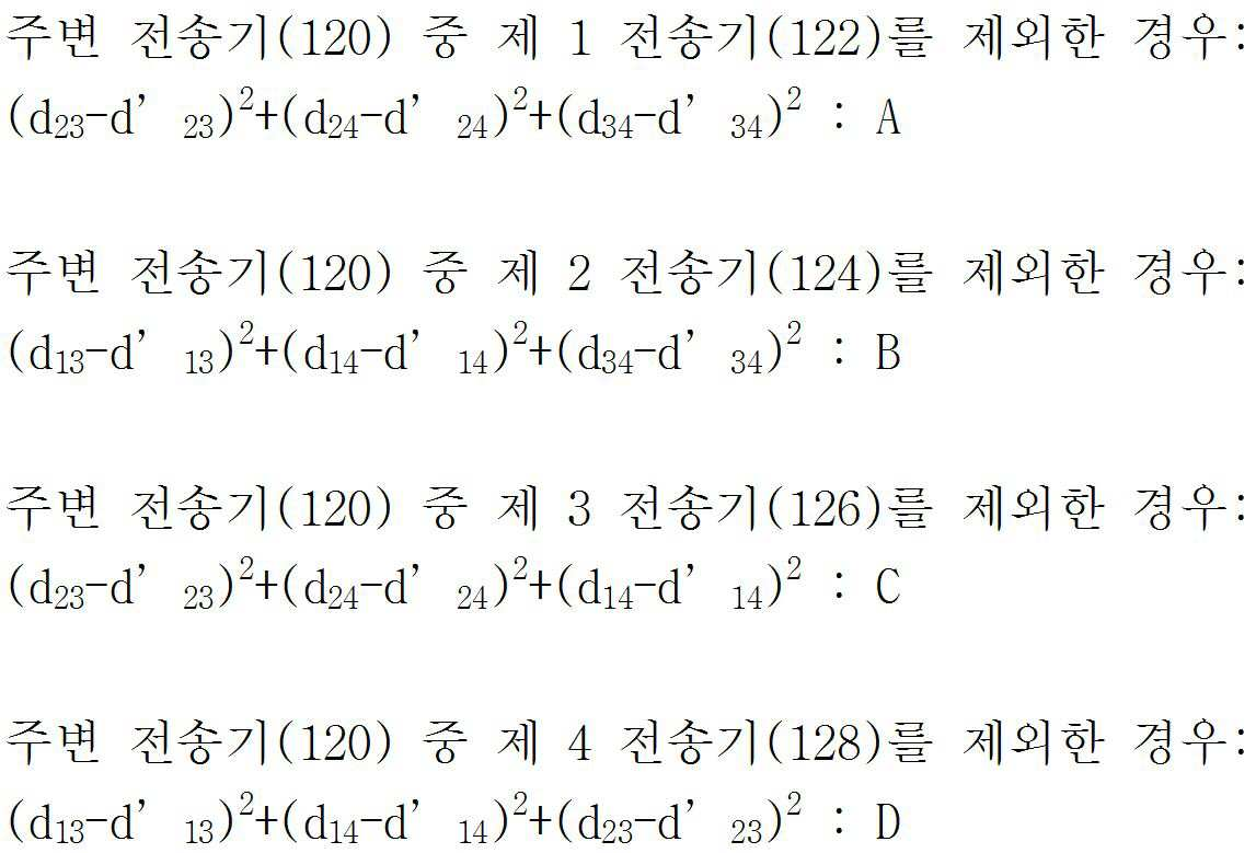
오차 요인 판별 장치(140)는 주변 전송기(120)에 포함되는 전송기(예컨대, 제 1 전송기(122) 내지 제 N 전송기(128)) 중 어느 하나를 제외한 그 나머지 전송기에 대한 차이값을 제곱하여 합산한 합산값을 주변 전송기(120)의 개수만큼 생성한다. 이때, 오차 요인 판별 장치(140)는 합산 과정에서 주변 전송기(120)에 포함되는 전송기(제 1 전송기(122) 내지 제 N 전송기(128)) 중 첫 번째 전송기부터 마지막 전송기까지 순차적으로 한 개의 전송기를 제외한 그 나머지 전송기에 대한 차이값을 제곱하여 합산값인 (d23-d`23)2+(d24-d`24)2+(d34-d`34)2:A, (d13-d`13)2+(d14-d`14)2+(d34-d`34)2:B, (d23-d`23)2+(d24-d`24)2+(d14-d`14)2:C... (dnm-d`nm)2+(dnm-d`nm)2+(dnm-d`nm)2:N을 주변 전송기 개수(N)만큼 생성할 수 있다.The error
오차 요인 판별 장치(140)는 주변 전송기 개수만큼 생성된 합산값을 중 최소값을 추출한다. 이때, 오차 요인 판별 장치(140)는 합산값(A, B, C... N)을 오름차순 또는 내림차순으로 정렬시킨 후 최소값을 추출한다. 오차 요인 판별 장치(140)는 최소값 산출 시 제외된 전송기를 오차 요인 전송기를 인식하여 제거 대상으로 선택한다. 이때, 오차 요인 판별 장치(140)는 제거 대상 선택 과정에서 합산값(A, B, C... N) 중 추출된 최소값에 해당하는 제외 전송기를 오차 요인 전송기로 인식하여 제거 대상으로 선택한다. 예컨대, 오차 요인 판별 장치(140)는 합산값인 A, B, C... N 중 최소값이 'A'로 추출된 경우, 'A'를 산출할 때 제외된 전송기를 확인한다. 이때, 합산값인 'A'를 산출할 때 제외된 전송기가 제 1 전송기(122)로 확인되는 경우, 제 1 전송기(122)를 오차 요인 전송기로 인식하여 제거 대상으로 선택하게 된다. 한편, 오차 요인 판별 장치(140)는 최소값이 'B'로 추출된 경우, 'B'를 산출할 때 제외된 전송기를 확인한다. 이때, 합산값인 'B'를 산출할 때 제외된 전송기가 제 2 전송기(124)로 확인되는 경우, 제 2 전송기(124)를 오차 요인 전송기로 인식하여 제거 대상으로 선택하게 된다. 한편, 오차 요인 판별 장치(140)는 최소값이 'C'로 추출된 경우, 'C'를 산출할 때 제외된 전송기를 확인한다. 이때, 합산값인 'C'를 산출할 때 제외된 전송기가 제 3 전송기(126)로 확인되는 경우, 제 3 전송기(126)를 오차 요인 전송기로 인식하여 제거 대상으로 선택하게 된다.The error
오차 요인 판별 장치(140)는 제거 대상에 해당하는 전송기를 제거한 후 주변 전송기(120) 중 제거 대상을 제거한 상태에서 추정 위치값`, 추정 전송기 거리값`을 산출하도록 하며, 주변 전송기(120)의 채널 상태 및 주변 전송기의 개수에 따라 오차 요인 전송기를 추가적으로 인식하도록 한다. 여기서, 추정 위치값`, 추정 전송기 거리값`은 주변 전송기(120) 중 제거 대상을 제거한 상태에서 다시 산출한 값을 말한다.The error
여기서, 오차 요인 판별 장치(140)가 채널 상태 및 주변 전송기의 개수에 따라 오차 요인 전송기를 추가적으로 인식하는 과정에 대해 보다 구체적으로 설명하자면, 오차 요인 판별 장치(140)는 주변 전송기(120)가 복수 개인 경우 생성된 합산값 중 최소값을 가질 때 제외된 전송기를 우선 제거하는데, 채널 상태에 따라 하나의 전송기뿐만 아니라 복수의 전송기가 측위에 오차를 야기할 수 있으므로, 채널 상태 및 전송기의 개수에 따라 오차 요인 전송기를 추가적으로 인식하는 과정을 반복하여 복수의 전송기를 제거할 수 있다. 이때, 오차 요인 판별 장치(140)가 오차 요인 전송기를 추가적으로 인식하는 반복 과정은 기 설정된 횟수가 반복되는 것이 아니라 전송기의 개수와 채널 상태에 따라 변화될 수 있다.Here, the error
이하, 오차 요인 판별 장치(140)가 전송 제어기(130)와 연동하여 단말기(110)와 단말기(110)에서 인식하는 주변 전송기(120)와의 신호 전송 시간이 확인되는지의 여부에 따라 단말기(110)의 위치값을 산출하는 과정에 대해 설명하자면, 오차 요인 판별 장치(140)는 단말기(110)와 주변 전송기(120) 간에 신호 전송 시간이 확인되는 경우, 신호 전송 시간을 근거로 확인 전송기 거리차 값을 산출한다. 즉, 오차 요인 판별 장치(140)는 단말기(110)와 단말기(110)에서 인식하는 주변 전송기(120) 간의 신호 전송 시간이 확인되는 경우, 단말기에 대한 확인 위치값(O) 또는 확인 위치값(O)을 기반으로 주변 전송기(120)까지의 거리인 확인 전송기 거리값(d1, d2, d3... dn)을 산출할 필요없이, 단말기(110)와 단말기(110)에서 인식하는 주변 전송기(120) 간의 신호 전송 시간 간의 차이를 통해, 확인 전송기 거리차 값(d12, d13, d14, d21, d23, d24.. dnm)을 산출할 수 있다. 물론, 오차 요인 판별 장치(140)는 필요에 따라 단말기(110)와 단말기(110)에서 인식하는 주변 전송기(120) 간의 신호 전송 시간과 확인 전송기 거리차 값(d12, d13, d14, d21, d23, d24.. dnm)에 근거하여 확인 위치값(O)과 확인 전송기 거리값(d1, d2, d3... dn)을 산출할 수 있을 것이다.Hereinafter, the terminal 110 determines whether the signal transmission time between the terminal 110 and the neighboring
한편, 오차 요인 판별 장치(140)는 단말기(110)와 주변 전송기(120) 간에 신호 전송 시간이 확인되지 않는 경우 TDoA(Time Difference of Arrival)를 이용하여 단말기(110)의 추정 위치인 추정 위치값(E)을 산출한다. 이때, 추정 위치값은 도 1에서 'E'에 해당한다. 이후, 오차 요인 판별 장치(140)는 추정 위치값(E)을 기준으로 주변 전송기(120)인 제 1 전송기(122) 내지 제 N 전송기(128)까지 거리인 추정 전송기 거리값(d1`, d2`, d3`... dn`)을 산출한다.On the other hand, the error
한편, 오차 요인 판별 장치(140)가 TDoA를 이용하여 단말기(110)의 추정 위치인 추정 위치값(E)을 산출하는 과정에 대해 보다 구체적으로 설명하자면 다음과 같다. 즉, TDoA는 단말기(110)와 주변 전송기(120) 간의 정확한 전송 시간을 확인할 수 없을 때 사용되는 일종의 알고리즘으로서, 주변 전송기(120)에 포함되는 제 1 전송기(122) 내지 제 N 전송기(128)에서 단말기(110)까지의 신호 전송 시간을 확인할 수가 없을 때 이용된다. 이때, 오차 요인 판별 장치(140)는 TDoA를 이용하여 제 1 전송기(122) 내지 제 N 전송기(128)에서 단말기(110)까지의 신호 전송 시간의 차이는 확인할 수 있다. 예컨대, 단말기(110)의 주변에 N 개의 전송기(제 1 전송기(122) 내지 제 N 전송기(128))가 위치한 경우, 제 1 전송기에서 단말기(110)까지의 신호 전송 시간과 제 2 전송기(124)에서 단말기(110)까지의 신호 전송 시간의 차이(제 1 전송기(122)에서 단말기(110)까지의 신호 전송 시간 - 제 2 전송기(124)에서 단말기(110)까지의 신호 전송 시간)를 확인할 수 있다. 이러한 방식으로 제 1 전송기(122)와 제 2 전송기(124)의 신호 전송 시간의 차이, 제 1 전송기(122)와 제 3 전송기(126)의 신호 전송 시간의 차이, 제 2 전송기(124)와 제 3 전송기(126)의 신호 전송 시간의 차이, 제 3 전송기(126)와 제 N 전송기(128)의 신호 전송 시간의 차이를 확인할 수 있다. Meanwhile, the process of calculating the estimated position value E, which is the estimated position of the terminal 110, by the error
오차 요인 판별 장치(140)는 이러한 각각의 신호 전송의 차이를 이용하여 거리값으로 환산을 할 수 있다.(즉, '거리 = 시간*빛의 속도') 이후 오차 요인 판별 장치(140)는 제 1 전송기(122) 내지 제 N 전송기(128)에서 동일한 거리 차이를 가지는 지점을 연결하면 쌍곡선의 형태로 그릴 수 있다. 이때, 오차 요인 판별 장치(140)는 제 1 전송기(122)와 제 2 전송기(124)에서 동일한 차이를 가지는 지점들을 모두 연결한다. 즉, 전술한 방식으로 오차 요인 판별 장치(140)는 제 1 전송기(122)와 제 3 전송기(126) 간의 쌍곡선, 제 2 전송기(124)와 제 3 전송기(126) 간의 쌍곡선, 제 2 전송기(124)와 제 N 전송기(128) 간의 쌍곡선을 모두 그리면 총 네 개의 쌍곡선이 그려지는데, 이 네 개의 쌍곡선이 모두 교차하는 지점의 좌표를 단말기(110)의 추정 위치인 추정 위치값(E)으로 산출할 수 있는 것이다.The error
한편, 위치 측위 기술로는 수신 각도를 이용한 AOA(Angle of Arrival), 신호 도달 시간을 이용한 ToA(Time of Arrival) 등이 있고, 앞서 언급한 신호 도달 시각차 방식인 TDoA를 이용해 쌍곡선을 그리고 이 쌍곡선들의 교점으로 타겟의 위치를 추정하는 기술이 있다. 이러한, TDoA는 무인항공 비행기, 항만 선박, 도로 자동차 주행 등에서 다양하게 활용되고 있으며, TDoA 방식의 경우에는 알고리즘 구현이 용이한 반면, 신호도달 시간에 대한 높은 정밀도가 요구됨으로 신호의 비가시선(NLOS) 효과 및 신호의 다중경로 페이딩으로 인한 신호지연 문제를 최소화해야 한다. 이러한 측정 신호에서의 오차를 보정하기 위한 방법으로 최소자승법(Least Squares)과 완전최소자승법(Total Least Squares) 등이 이용되고 있는데, 이동통신 기술에 따라 실내 또는 실외 환경에서도 사용자 및 타겟에 대한 위치를 추정할 수 있다.On the other hand, positioning techniques include AOA (Angle of Arrival) using a reception angle and ToA (Time of Arrival) using a signal arrival time, and a hyperbolic curve is drawn using TDoA, the signal arrival time difference method described above. There is a technique for estimating the position of the target by the intersection. The TDoA is widely used in unmanned aerial vehicles, port ships, and road car driving. In the case of the TDoA method, the algorithm is easy to implement, while the high precision of the signal arrival time is required. Signal delay problems due to effects and multipath fading of signals should be minimized. Least Squares and Total Least Squares are used to compensate for the error in the measurement signal. It can be estimated.
이러한, 측위 기술 중에서도 TDoA는 송수신기 간에 시간 동기를 시킬 필요가 없기 때문에 별도의 하드웨어 없이도 ToA와 유사하거나 향상된 위치 측위를 수행할 수 있다. TDoA 방식의 경우 ToA와 유사한 기술이나 단말기(110)로부터 수신된 신호가 복수의 전송기에 도달한 신호의 상대적인 전송 시간 차이를 이용하여 쌍곡선 위치 궤적으로 위치가 결정되어짐으로 신호 도달 시간에 대한 높은 정밀도가 요구되는데, 이는 신호의 비가시선(NLOS) 효과와 가시선(LOS) 효과를 구분할 수 있다면 그 정밀도가 향상되며, TDoA 측위 기술의 정확도를 향상시키기 위해 시간 신호의 오류 보정이 필요하다. 이에 본 실시예에 따른 오차 요인 판별 장치(140)를 통해 오차 요인에 해당하는 전송기를 선별하여 제거하는 것이다.Among these positioning techniques, since TDoA does not need to synchronize time between transceivers, TDoA can perform similar or improved positioning with ToA without additional hardware. In the case of the TDoA method, a position similar to ToA or a signal received from the terminal 110 is determined by a hyperbolic position trajectory using a relative transmission time difference of a signal reaching a plurality of transmitters, thereby providing high accuracy for signal arrival time. This is required if the invisible line (NLOS) effect and the line of sight (LOS) effect of the signal can be distinguished, and the accuracy is improved, and error correction of the time signal is required to improve the accuracy of the TDoA positioning technique. Accordingly, the error
이하, 오차 요인 판별 장치(140)가 주변 전송기(120)에 포함되는 전송기(제 1 전송기(122) 내지 제 N 전송기(128)) 간의 거리차를 산출하는 과정에 대해 설명하자면, 오차 요인 판별 장치(140)는 단말기(110)와 주변 전송기(120) 간에 신호 전송 시간이 확인되는 경우, 주변 전송기 각각에 대한 신호 전송 시간 간의 차이를 이용하여 확인 전송기 거리차 값(d12, d13, d14, d21, d23, d24.. dnm)을 산출한다. 한편, 오차 요인 판별 장치(140)는 추정 위치값(E)과 추정 전송기 거리값(d1`, d2`, d3`... dn`)을 근거로 주변 전송기(120)에 포함되는 전송기(제 1 전송기(122) 내지 제 N 전송기(128)) 간의 거리차인 추정 전송기 거리차 값인 d`12, d`13, d`14, d`21, d`23, d`24.. d`nm을 산출한다.Hereinafter, a process of calculating the distance difference between the transmitters (the
도 2는 본 실시예에 따른 오차 요인 판별 장치를 개략적으로 나타낸 블럭 구성도이다.2 is a block diagram schematically showing an error factor determining apparatus according to the present embodiment.
본 실시예에 따른 오차 요인 판별 장치(140)는 거리 산출부(210), 거리차 산출부(220), 오차 요인 판별부(230)를 포함한다. 본 실시예에서는 오차 요인 판별 장치(140)가 거리 산출부(210), 거리차 산출부(220), 오차 요인 판별부(230)만을 포함하는 것으로 기재하고 있으나, 이는 본 실시예의 기술 사상을 예시적으로 설명한 것에 불과한 것으로서, 본 실시예가 속하는 기술 분야에서 통상의 지식을 가진 자라면 본 실시예의 본질적인 특성에서 벗어나지 않는 범위에서 오차 요인 판별 장치(140)에 포함되는 구성 요소에 대하여 다양하게 수정 및 변형하여 적용 가능할 것이다.The error
거리 산출부(210)는 단말기(110)와 단말기(110)에서 인식하는 주변 전송기(120) 간의 신호 도달 시각차를 근거로 단말기(110)에 대한 추정 위치값을 산출하고, 추정 위치값을 기반으로 각각의 주변 전송기(120)까지의 거리인 추정 전송기 거리값을 산출한다. 즉, 거리 산출부(210)는 단말기(110)와 주변 전송기(120) 간에 신호 전송 시간이 확인되는 경우, 주변 전송기 각각에 대한 신호 전송 시간 간의 차이를 이용하여 확인 전송기 거리차 값인 d12, d13, d14, d21, d23, d24.. dnm을 산출한다. The
한편, 거리 산출부(210)는 단말기(110)와 주변 전송기(120) 간에 신호 전송 시간이 확인되지 않는 경우 TDoA를 이용하여 단말기(110)의 추정 위치인 추정 위치값(E)을 산출한다. 이후, 거리 산출부(210)는 추정 위치값(E)을 기준으로 주변 전송기(120)까지 거리인 추정 전송기 거리값인 d1`, d2`, d3`... dn`을 산출한다. 즉, 거리 산출부(210)는 주변 전송기(120)에 포함되는 제 1 전송기(122) 내지 제 N 전송기(128)에서 단말기(110)까지의 신호 전송 시간을 확인할 수 없는 경우 TDoA를 이용한다. 즉, 거리 산출부(210)는 신호 전송 시간을 확인할 수 없는 경우에도 TDoA를 이용하여 제 1 전송기(122) 내지 제 N 전송기(128)에서 단말기(110)까지의 신호 전송 시간의 차이는 확인할 수 있다. 예컨대, 단말기(110)의 주변에 N 개의 전송기(제 1 전송기(122) 내지 제 N 전송기(128))가 위치한 경우, 거리 산출부(210)는 제 1 전송기에서 단말기(110)까지의 신호 전송 시간과 제 2 전송기(124)에서 단말기(110)까지의 신호 전송 시간의 차이(제 1 전송기(122)에서 단말기(110)까지의 신호 전송 시간 - 제 2 전송기(124)에서 단말기(110)까지의 신호 전송 시간)를 확인할 수 있다. 거리 산출부(210)는 이러한 방식으로 제 1 전송기(122)와 제 2 전송기(124)의 신호 전송 시간의 차이, 제 1 전송기(122)와 제 3 전송기(126)의 신호 전송 시간의 차이, 제 2 전송기(124)와 제 3 전송기(126)의 신호 전송 시간의 차이, 제 3 전송기(126)와 제 N 전송기(128)의 신호 전송 시간의 차이를 산출할 수 있다. 거리 산출부(210)는 이러한, 각각의 신호 전송의 차이를 이용하여 거리값을 환산할 수 있다.(즉, '거리 = 시간*빛의 속도') 이후 제 1 전송기(122) 내지 제 N 전송기(128)에서 동일한 거리 차이를 가지는 지점을 연결하면 쌍곡선의 형태로 그릴 수가 있다. 이때, 거리 산출부(210)는 제 1 전송기(122)와 제 2 전송기(124)에서 동일한 차이를 가지는 지점들을 모두 연결한다. 즉, 전술한 방식으로 거리 산출부(210)는 제 1 전송기(122)와 제 3 전송기(126) 간의 쌍곡선, 제 2 전송기(124)와 제 3 전송기(126) 간의 쌍곡선, 제 2 전송기(124)와 제 N 전송기(128) 간의 쌍곡선을 모두 그리면 총 네 개의 쌍곡선이 그려지는데, 이 네 개의 쌍곡선이 모두 교차하는 지점의 좌표를 단말기(110)의 추정 위치인 추정 위치값(E)으로 산출할 수 있는 것이다.On the other hand, when the signal transmission time is not confirmed between the terminal 110 and the
거리차 산출부(220)는 단말기(110)와 주변 전송기(120) 간에 신호 전송 시간이 확인되는 경우, 신호 전송 시간을 근거로 확인 전송기 거리차 값을 산출한다. 즉, 거리차 산출부(220)는 단말기(110)와 단말기(110)에서 인식하는 주변 전송기(120) 간의 신호 전송 시간이 확인되는 경우, 단말기에 대한 확인 위치값(O) 또는 확인 위치값(O)을 기반으로 주변 전송기(120)까지의 거리인 확인 전송기 거리값(d1, d2, d3... dn)을 산출할 필요없이, 단말기(110)와 단말기(110)에서 인식하는 주변 전송기(120) 간의 신호 전송 시간 간의 차이를 통해, 확인 전송기 거리차 값(d12, d13, d14, d21, d23, d24.. dnm)을 산출할 수 있다. 물론, 거리차 산출부(220)는 필요에 따라 단말기(110)와 단말기(110)에서 인식하는 주변 전송기(120) 간의 신호 전송 시간과 확인 전송기 거리차 값(d12, d13, d14, d21, d23, d24.. dnm)에 근거하여 확인 위치값(O)과 확인 전송기 거리값(d1, d2, d3... dn)을 산출할 수 있을 것이다.When the signal transmission time is confirmed between the terminal 110 and the
오차 요인 판별부(230)는 확인 전송기 거리차 값과 추정 전송기 거리차 값의 차이값에 근거하여 오차 요인 전송기를 인식한다. 한편, 오차 요인 판별부(230)는 차이값 획득부(240), 합산부(250), 추출부(260), 선택부(270), 제거부(280) 및 반복부(290)를 포함한다. 차이값 획득부(240)는 확인 전송기 거리차 값과 추정 전송기 거리차 값에 근거하여 차이값을 획득한다. 즉, 차이값 획득부(240)는 확인 전송기 거리차 값과 추정 전송기 거리차 값 간의 차이값인 d12-d`12, d13-d`13, d14-d`14, d21-d`21, d23-d`23, d24-d`24.. dnm-d`nm을 획득한다.The error
합산부(250)는 주변 전송기(120)에 포함되는 전송기 중 어느 하나를 제외한 그 나머지 전송기에 대한 차이값을 제곱하여 합산한 합산값을 주변 전송기 개수만큼 생성한다. 즉, 합산부(250)는 주변 전송기(120)에 포함되는 전송기 중 첫 번째 전송기부터 마지막 전송기까지 순차적으로 한 개의 전송기를 제외한 그 나머지 전송기에 대한 차이값을 제곱하여 합산값인 (d23-d`23)2+(d24-d`24)2+(d34-d`34)2:A, (d13-d`13)2+(d14-d`14)2+(d34-d`34)2:B, (d23-d`23)2+(d24-d`24)2+(d14-d`14)2:C... (dnm-d`nm)2+(dnm-d`nm)2+(dnm-d`nm)2:N을 주변 전송기 개수(N)만큼 생성한다. 추출부(260)는 주변 전송기 개수만큼 생성된 합산값을 중 최소값을 추출한다. 즉, 추출부(260)는 합산부(250)를 통해 생성된 합산값인 A, B, C... N을 오름차순 또는 내림차순으로 정렬시킨 후 최소값을 추출한다.The
선택부(270)는 최소값 산출 시 제외된 전송기를 오차 요인 전송기를 인식하여 제거 대상으로 선택한다. 즉, 선택부(270)는 합산값인 A, B, C... N 중 추출된 최소값에 해당하는 제외 전송기를 오차 요인 전송기로 인식하여 제거 대상으로 선택한다. 예컨대, 선택부(270)는 추출부(260)를 통해 합산값인 A, B, C... N 중 최소값이 'A'로 추출된 경우, 'A'를 산출할 때 제외된 전송기를 확인한다. 이때, 합산값인 'A'를 산출할 때 제외된 전송기가 제 1 전송기(122)로 확인되는 경우, 제 1 전송기(122)를 오차 요인 전송기로 인식하여 제거 대상으로 선택하게 된다. 한편, 선택부(270)는 추출부(260)를 통해 최소값이 'B'로 추출된 경우, 'B'를 산출할 때 제외된 전송기를 확인한다. 이때, 합산값인 'B'를 산출할 때 제외된 전송기가 제 2 전송기(124)로 확인되는 경우, 제 2 전송기(124)를 오차 요인 전송기로 인식하여 제거 대상으로 선택하게 된다. 한편, 선택부(270)는 추출부(260)를 통해 최소값이 'C'로 추출된 경우, 'C'를 산출할 때 제외된 전송기를 확인한다. 이때, 합산값인 'C'를 산출할 때 제외된 전송기가 제 3 전송기(126)로 확인되는 경우, 제 3 전송기(126)를 오차 요인 전송기로 인식하여 제거 대상으로 선택하게 된다.The
제거부(280)는 제거 대상에 해당하는 전송기를 제거한 후 거리 산출부(210)로 하여금, 주변 전송기(120) 중 제거 대상을 제거한 상태에서 추정 위치값`, 추정 전송기 거리값`을 산출하도록 한다. 여기서, 추정 위치값`, 추정 전송기 거리값`은 주변 전송기(120) 중 제거 대상을 제거한 상태에서 다시 산출한 값을 말한다. 반복부(290)는 주변 전송기(120)의 채널 상태 및 주변 전송기(120)의 개수에 따라 선택부(270)로 하여금 오차 요인 전송기를 추가적으로 인식하도록 한다.The
도 3은 본 실시예에 따른 오차 요인 판별 방법을 설명하기 위한 순서도이다.3 is a flowchart illustrating a method of determining an error factor according to the present embodiment.
오차 요인 판별 장치(140)는 단말기(110)와 단말기(110)에서 인식하는 주변 전송기(120) 간의 신호 전송 시간과 신호 도달 시각차를 근거로 단말기(110)에 대한 추정 위치값을 산출하고, 추정 위치값을 기반으로 각각의 주변 전송기(120)까지의 거리인 추정 전송기 거리값을 산출한다(S310). 단계 S310에서 오차 요인 판별 장치(140)는 단말기(110)와 주변 전송기(120) 간에 신호 전송 시간이 확인되지 않는 경우 TDoA를 이용하여 단말기(110)의 추정 위치인 추정 위치값(E)을 산출한다. 이후, 오차 요인 판별 장치(140)는 추정 위치값(E)을 기준으로 주변 전송기(120)인 제 1 전송기(122) 내지 제 N 전송기(128)까지 거리인 추정 전송기 거리값(d1`, d2`, d3`... dn`)을 산출한다.The error
오차 요인 판별 장치(140)는 추정 위치값과 추정 전송기 거리값을 기반으로 각각의 주변 전송기(120) 간의 거리차인 추정 전송기 거리차 값을 산출한다(S320). 단계 S320에서, 오차 요인 판별 장치(140)는 추정 위치값(E)과 추정 전송기 거리값(d1`, d2`, d3`... dn`)을 근거로 주변 전송기(120)에 포함되는 전송기(제 1 전송기(122) 내지 제 N 전송기(128)) 간의 거리차인 추정 전송기 거리차 값인 d`12, d`13, d`14, d`21, d`23, d`24.. d`nm을 산출한다.The error
오차 요인 판별 장치(140)는 확인 전송기 거리차 값과 추정 전송기 거리차 값에 근거하여 차이값을 획득한다(S330). 단계 S330에서, 오차 요인 판별 장치(140)는 확인 전송기 거리차 값과 추정 전송기 거리차 값 간의 차이값인 d12-d`12, d13-d`13, d14-d`14, d21-d`21, d23-d`23, d24-d`24.. dnm-d`nm을 획득할 수 있다. 이때, 오차 요인 판별 장치(140)는 단말기(110)와 주변 전송기(120) 간에 신호 전송 시간이 확인되는 경우, 단말기(110)와 단말기(110)에서 인식하는 주변 전송기(120) 간의 신호 전송 시간 간의 차이를 통해, 확인 전송기 거리차 값인 d12, d13, d14, d21, d23, d24.. dnm을 이용한다.The error
오차 요인 판별 장치(140)는 주변 전송기(120)에 포함되는 전송기(예컨대, 제 1 전송기(122) 내지 제 N 전송기(128)) 중 어느 하나를 제외한 그 나머지 전송기에 대한 차이값을 제곱하여 합산한 합산값을 주변 전송기(120)의 개수만큼 생성한다(S340). 단계 S340에서, 오차 요인 판별 장치(140)는 합산 과정에서 주변 전송기(120)에 포함되는 전송기(제 1 전송기(122) 내지 제 N 전송기(128)) 중 첫 번째 전송기부터 마지막 전송기까지 순차적으로 한 개의 전송기를 제외한 그 나머지 전송기에 대한 차이값을 제곱하여 합산값인 (d23-d`23)2+(d24-d`24)2+(d34-d`34)2:A, (d13-d`13)2+(d14-d`14)2+(d34-d`34)2:B, (d23-d`23)2+(d24-d`24)2+(d14-d`14)2:C... (dnm-d`nm)2+(dnm-d`nm)2+(dnm-d`nm)2:N을 주변 전송기 개수(N)만큼 생성할 수 있다.The error
오차 요인 판별 장치(140)는 주변 전송기 개수만큼 생성된 합산값을 중 최소값을 추출한다(S350). 단계 S350에서, 오차 요인 판별 장치(140)는 합산값(A, B, C... N)을 오름차순 또는 내림차순으로 정렬시킨 후 최소값을 추출한다. 오차 요인 판별 장치(140)는 최소값 산출 시 제외된 전송기를 오차 요인 전송기를 인식하여 제거 대상으로 선택한다(S360). 단계 S360에서, 오차 요인 판별 장치(140)는 제거 대상 선택 과정에서 합산값(A, B, C... N) 중 추출된 최소값에 해당하는 제외 전송기를 오차 요인 전송기로 인식하여 제거 대상으로 선택한다. The error
오차 요인 판별 장치(140)는 제거 대상에 해당하는 전송기를 제거한 후 주변 전송기(120) 중 제거 대상을 제거한 상태에서 추정 위치값`, 추정 전송기 거리값`을 산출하도록 한다(S370). 여기서, 추정 위치값`, 추정 전송기 거리값`은 주변 전송기(120) 중 제거 대상을 제거한 상태에서 다시 산출한 값을 말한다. 오차 요인 판별 장치(140)는 주변 전송기(120)의 채널 상태 및 주변 전송기의 개수에 따라 오차 요인 전송기를 추가적으로 인식하도록 한다(S380). The error
도 3에서는 단계 S310 내지 단계 S380을 순차적으로 실행하는 것으로 기재하고 있으나, 이는 본 실시예의 기술 사상을 예시적으로 설명한 것에 불과한 것으로서, 본 실시예가 속하는 기술 분야에서 통상의 지식을 가진 자라면 본 실시예의 본질적인 특성에서 벗어나지 않는 범위에서 도 3에 기재된 순서를 변경하여 실행하거나 단계 S310 내지 단계 S380 중 하나 이상의 단계를 병렬적으로 실행하는 것으로 다양하게 수정 및 변형하여 적용 가능할 것이므로, 도 3은 시계열적인 순서로 한정되는 것은 아니다.In FIG. 3, steps S310 to S380 are described as being sequentially executed. However, this is merely illustrative of the technical idea of the present embodiment, and those of ordinary skill in the art to which the present embodiment pertains will be described. 3 may be modified and modified in various manners by changing the order described in FIG. 3 or executing one or more steps of steps S310 to S380 in parallel without departing from the essential characteristics, and thus, FIG. It is not limited.
전술한 바와 같이 도 3에 기재된 본 실시예에 따른 오차 요인 판별 방법은 프로그램으로 구현되고 컴퓨터로 읽을 수 있는 기록매체에 기록될 수 있다. 본 실시예에 따른 오차 요인 판별 방법을 구현하기 위한 프로그램이 기록되고 컴퓨터가 읽을 수 있는 기록매체는 컴퓨터 시스템에 의하여 읽혀질 수 있는 데이터가 저장되는 모든 종류의 기록장치를 포함한다. 이러한 컴퓨터가 읽을 수 있는 기록매체의 예로는 ROM, RAM, CD-ROM, 자기 테이프, 플로피디스크, 광 데이터 저장장치 등이 있으며, 또한 캐리어 웨이브(예를 들어, 인터넷을 통한 전송)의 형태로 구현되는 것도 포함한다. 또한 컴퓨터가 읽을 수 있는 기록매체는 네트워크로 연결된 컴퓨터 시스템에 분산되어, 분산방식으로 컴퓨터가 읽을 수 있는 코드가 저장되고 실행될 수도 있다. 또한, 본 실시예를 구현하기 위한 기능적인(Functional) 프로그램, 코드 및 코드 세그먼트들은 본 실시예가 속하는 기술분야의 프로그래머들에 의해 용이하게 추론될 수 있을 것이다.As described above, the error factor determining method according to the present embodiment described in FIG. 3 may be implemented in a program and recorded in a computer-readable recording medium. The computer-readable recording medium having recorded thereon a program for implementing the error factor determining method according to the present embodiment includes all kinds of recording devices storing data that can be read by a computer system. Examples of such computer-readable recording media include ROM, RAM, CD-ROM, magnetic tape, floppy disk, optical data storage, etc., and also implemented in the form of a carrier wave (e.g., transmission over the Internet) . The computer readable recording medium may also be distributed over a networked computer system so that computer readable code is stored and executed in a distributed manner. In addition, functional programs, codes, and code segments for implementing the present embodiment can be easily inferred by programmers in the technical field to which the present embodiment belongs.
도 4는 본 실시예에 따른 오차 요인 판별을 위한 예시도이다.4 is an exemplary view for error factor determination according to the present embodiment.
일반적으로 단말기(110)의 위치를 산출하기 위한 대부분 방법으로는 GPS를 이용한 방법이 이용되고 있다. 하지만, 단말기(110)가 GPS를 탑재하지 않거나 GPS 음영 지역인 경우 측위 시스템에서는 전파의 도달 시간이나 전파의 도달 각도, 전파의 도달 세기 등을 이용한다. 이때, 한가지 방식만을 이용할 때 발생하는 오차를 보상하기 위한 방편으로 둘 이상의 방법을 하이브리드 형태로 이용하기도 하지만 전술한 방식 중 전파의 도달 시간을 이용하는 방식이 가장 선호되고 있다. In general, a method using a GPS is used as a method for calculating the position of the terminal 110. However, when the terminal 110 is not equipped with GPS or is in a GPS shaded area, the positioning system uses the arrival time of the radio wave, the angle of arrival of the radio wave, the intensity of arrival of the radio wave, and the like. In this case, two or more methods may be used in a hybrid form as a means of compensating for an error occurring when only one method is used, but the method using the arrival time of the radio wave is most preferred among the above-described methods.
도 4와 연관지어 설명하자면, 주변 전송기(120)에 포함되는 각각의 전송기(제 1 전송기(122) 내지 제 4 전송기(128))에서 단말기(110)로 전파의 도달 시간에 대한 절대값을 확인할 수 있는 경우에는 TOA 방식을 이용하고, 주변 전송기(120)에 포함되는 각각의 전송기(제 1 전송기(122) 내지 제 4 전송기(128))에서의 도달 시간의 차이만을 확인할 수 있는 경우에는 TDoA 방식을 이용하게 된다.Referring to FIG. 4, the absolute value of the arrival time of the radio wave from each transmitter (the
이때, 제 1 전송기(122) 내지 제 4 전송기(128)에서 단말기(110)로의 채널의 임펄스 응답은 시간에 따라 확산 형태를 띠며 변하는 것이 일반적이다. 이렇게 지연 확산을 가지는 수신 신호에서 어느 시간 위치를 전파의 도달 시간으로 보느냐의 문제가 발생하는데, 이러한 문제를 해결하기 위해서는 결국 선택의 문제가 발생한다. 예컨대, 가장 수신 세기가 센 지연 탭의 위치를 전파의 도달 시간으로 볼 수도 있고, 문턱 값을 넘으면서 가장 일찍 도착하는 지연 탭의 위치를 전파의 도달 시간으로 볼 수도 있다.In this case, the impulse response of the channel from the
한편, 이러한 선택은 방법에 따라 우열이 있을 수 있으나 결과적으로 정확한 값을 추출해 내는 데 한계가 있다. 이에, 전파의 도달 각도를 이용한 측위의 경우 위치결정 자체는 간단하지만, 기본적으로 가시선(LOS) 신호 성분을 가정하고 있으므로, 전파의 파동성으로 인한 비가시선 신호 수신 시 큰 오차가 발생한다. 특히, 제 1 전송기(122) 내지 제 4 전송기(128)와 단말기(110)의 거리가 멀수록 작은 각도 오차가 큰 거리오차를 유발하기 때문에 사용이 제한적이다. 전파의 도달 거리에 따라 일정하게 수신 신호의 전력이 감소하는 특징을 이용하면 수신 신호의 세기를 바탕으로 한 거리를 도출할 수 있으나, 도심 및 부도심에서의 비선형적인 경로 감쇄와 페이딩 현상 등으로 인해 측위 성능이 떨어지는 현상이 있다. 즉, 전파의 지연 확산을 이용한 제 1 전송기(122) 내지 제 4 전송기(128)와 단말기(110) 간의 거리를 추정해보면, 제 1 전송기(122) 내지 제 4 전송기(128)와 단말기(110) 간의 거리가 멀어지면 각 지연이 거리에 비례하여 늘어지게 되므로 지연 사이의 차이도 거리 차이에 비례하여 커진다. 즉, 거리가 두 배로 멀어지면 지연 확산도 두 배로 늘어나게 된다. On the other hand, this choice may have superiority depending on the method, but as a result, there is a limit in extracting the correct value. Therefore, in the case of positioning using the arrival angle of radio waves, positioning itself is simple, but since the line of sight (LOS) signal component is basically assumed, a large error occurs when receiving an invisible line signal due to wave propagation. In particular, as the distance between the
이와 같이 간단한 환경을 가정하여 보았을 때, 전파 지연의 분포는 제 1 전송기(122) 내지 제 4 전송기(128)와 단말기(110) 간의 거리에 비례하여 시간 축으로 확대 및 축소되는 형태를 가짐을 예상할 수 있으며, 전파 지연의 분포를 관찰하여 역으로 제 1 전송기(122) 내지 제 4 전송기(128)와 단말기(110) 간의 거리 정보를 획득할 수 있다. 지연 확산과 송수신 거리 사이에는 선형적인 관계가 존재함을 확인할 수 있으나, 측정된 지연 분포로부터 지연 확산값, 제 1 전송기(122) 내지 제 4 전송기(128)로 보고할 정보 또는 거리로 변환할 척도를 어떻게 추출하는지는 여러 방법이 있을 수 있다. 즉, 수신된 전파의 지연으로부터 평균 수신 신호 세기를 감안하여 문턱값 이상인 지연들 중 최소 지연값과 최대 지연값의 차이를 이용하거나, 표준편차, Weighted RMS(Root Mean Square)값을 이용할 수 있다.Assuming such a simple environment, it is expected that the distribution of the propagation delay has a form of expanding and contracting on the time axis in proportion to the distance between the
한편, 본 실시예에 따른 d1, d2 , d3 , d4는 도 4에 도시된 바와 같이, 제 1 전송기(122) 내지 제 4 전송기(128)와 확인 위치값(O)에 존재하는 단말기(110) 간의 거리를 나타낸다. 즉, d1, d2 , d3 , d4는 제 1 전송기(122) 내지 제 4 전송기(128)에서 단말기(110)까지의 신호 전송 시간을 정확히 확인할 수 있을 때 그 신호 전송 시간을 이용하여 거리로 환산한 거리값이다. 또한, d12, d13, d14, d21, d23, d24… d43의 경우 전술한 바와 같이 제 1 전송기(122) 내지 제 4 전송기(128)에서 단말기(110)까지의 신호 전송 시간의 차이를 거리로 환산하여 나타낸 것이다.Meanwhile, d 1 , d 2 , d 3 , and d 4 according to the present embodiment are present in the
즉, 도 4에 도시된 바와 같이, 주변 전송기(120)가 제 1 전송기(122) 내지 제 4 전송기(128)를 포함하는 경우, 오차 요인 판별 장치(140)는 주변 전송기(120)에 포함된 제 1 전송기(122) 내지 제 4 전송기(128) 각각으로부터 획득되는 시간차를 이용하여 거리차를 구하고 이를 d12, d13, d14, d21, d23, d24… d43의 형태로 나타낼 수 있다. That is, as shown in FIG. 4, when the
또한, 오차 요인 판별 장치(140)는 신호 도달 시각차를 이용하여 TDoA 알고리즘으로 단말기(110)의 위치를 추정하면 추정된 추정 위치값(E)을 얻을 수 있다. 여기서, 추정 위치값은 도 4에 도시된 '★'에 해당한다. 오차 요인 판별 장치(140)는 추정된 위치값인 추정 위치값(E)에서 각 전송기인 제 1 전송기(122) 내지 제 4 전송기(128)까지 거리를 산출할 수 있으므로 추정 위치값(E)을 기반으로 추정 위치값과 제 1 전송기(122) 내지 제 4 전송기(128)까지의 거리차이를 산출한다. 이때, 오차 요인 판별 장치(140)에 의해 산출된 거리차는 d’12, d’13, d’14, d’21, d’23, d’24…. d’43로 표현할 수 있다. In addition, the error
한편, 오차 요인 판별 장치(140)는 단말기(110)와 주변 전송기(120) 간에 신호 전송 시간이 확인되는 경우, 신호 전송 시간을 근거로 확인 전송기 거리차 값인 d12, d13, d14, d21, d23, d24.. dnm을 산출할 수 있다. 즉, 오차 요인 판별 장치(140)는 단말기(110)와 단말기(110)에서 인식하는 주변 전송기(120) 간의 신호 전송 시간이 확인되는 경우, 단말기에 대한 확인 위치값(O) 또는 확인 위치값(O)을 기반으로 주변 전송기(120)까지의 거리인 확인 전송기 거리값(d1, d2, d3... dn)을 산출할 필요없이, 단말기(110)와 단말기(110)에서 인식하는 주변 전송기(120) 간의 신호 전송 시간 간의 차이를 통해, 확인 전송기 거리차 값(d12, d13, d14, d21, d23, d24.. dnm)을 산출할 수 있다. 물론, 오차 요인 판별 장치(140)는 필요에 따라 단말기(110)와 단말기(110)에서 인식하는 주변 전송기(120) 간의 신호 전송 시간과 확인 전송기 거리차 값(d12, d13, d14, d21, d23, d24.. dnm)에 근거하여 확인 위치값(O)과 확인 전송기 거리값(d1, d2, d3... dn)을 산출할 수 있을 것이다. 이때, 확인 위치값은 도 4에서 도시된 '●'에 해당한다. Meanwhile, when the signal transmission time is confirmed between the terminal 110 and the
오차 요인 판별 장치(140)는 단말기(110)와 단말기(110)에서 인식하는 주변 전송기(120) 간의 신호 전송 시간과 신호 도달 시각차를 근거로 단말기(110)에 대한 추정 위치값을 산출하고, 추정 위치값(E)을 기반으로 각각의 주변 전송기(120)까지의 거리인 추정 전송기 거리값을 산출하고, 추정 위치값과 추정 전송기 거리값을 기반으로 각각의 주변 전송기(120) 간의 거리차인 추정 전송기 거리차 값을 산출하며, 확인 전송기 거리차 값과 추정 전송기 거리차 값의 차이값에 근거하여 오차 요인 전송기를 인식한다.The error
또한, 오차 요인 판별 장치(140)는 단말기(110)와 주변 전송기(120) 간에 신호 전송 시간이 확인된 경우, 단말기(110)와 주변 전송기(120) 간의 신호 전송 시간을 근거로 산출된 확인 전송기 거리차 값과 추정 전송기 거리차 값의 차이값을 구한다. 여기서, 전파지연 또는 시간의 오차가 없다면 이 두 시간의 차이값은 '0'이 될 수 있지만, 여러 간섭의 영향으로 두 시간의 차이값이 존재한다. In addition, when the signal transmission time between the terminal 110 and the
이러한, 문제를 해결하기 위해 오차 요인 판별 장치(140)는 제 1 전송기(122) 내지 제 4 전송기(128) 중 간섭의 영향으로 시간의 오차가 가장 크게 발생한 전송기를 선별하여 제거한다. 이때, 오차 요인 판별 장치(140)는 전송기를 제거하기 위해서, 제 1 전송기(122) 내지 제 4 전송기(128) 중 제 1 전송기(122)를 제외한 나머지 제 2 전송기(124), 제 3 전송기(126) 및 제 4 전송기(128)의 거리차를 제곱해서 모두 더한 합산값을 생성한다. 여기서, 합산값은 [수학식 1]을 이용하여 생성할 수 있다. 이러한 합산값 생성 방식은 거리차를 제곱하여 더하면 거리 차이의 크기값의 분포를 확인할 수 있으며 이러한 크기값이 작을 경우 오류가 큰 전송기를 제거한 것으로 판별할 수 있는 근거가 될 수 있다.In order to solve such a problem, the error
전술한 [수학식 1]에서 만약 B의 값이 최소값에 해당하는 경우, 오차 요인 판별 장치(140)는 제 2 전송기(124)가 실제값과 계산값의 차이를 유발하였다고 판단할 수 있고, 제 2 전송기(124)를 제외하고 다시 단말기(110)에 대한 추정 위치값`, 추정 전송기 거리값`을 산출할 수 있다. 이렇듯 각 전송기를 제외한 오차값을 기준으로 어느 전송기의 영향으로 위치성능이 낮아졌는지를 확인하여 위치 오차를 가장 크게 유발하는 전송기를 제거함으로써 위치 측위의 성능을 높일 수 있다.In the above Equation 1, if the value of B corresponds to the minimum value, the error
이상의 설명은 본 실시예의 기술 사상을 예시적으로 설명한 것에 불과한 것으로서, 본 실시예가 속하는 기술 분야에서 통상의 지식을 가진 자라면 본 실시예의 본질적인 특성에서 벗어나지 않는 범위에서 다양한 수정 및 변형이 가능할 것이다. 따라서, 본 실시예들은 본 실시예의 기술 사상을 한정하기 위한 것이 아니라 설명하기 위한 것이고, 이러한 실시예에 의하여 본 실시예의 기술 사상의 범위가 한정되는 것은 아니다. 본 실시예의 보호 범위는 아래의 청구범위에 의하여 해석되어야 하며, 그와 동등한 범위 내에 있는 모든 기술 사상은 본 실시예의 권리범위에 포함되는 것으로 해석되어야 할 것이다.The foregoing description is merely illustrative of the technical idea of the present embodiment, and various modifications and changes may be made to those skilled in the art without departing from the essential characteristics of the embodiments. Therefore, the present embodiments are to be construed as illustrative rather than restrictive, and the scope of the technical idea of the present embodiment is not limited by these embodiments. The scope of protection of the present embodiment should be construed according to the following claims, and all technical ideas within the scope of equivalents thereof should be construed as being included in the scope of the present invention.
이상에서 설명한 바와 같이 본 실시예는 지국(전송기) 기반의 측위 성능을 높일 수 있도록 하는 다양한 분야에 적용되어, 측정된 신호 전송 시간을 이용하여 위치 측위를 한번 수행하고 그 후 오차 요인이 되는 기지국(전송기)을 선별하여 제외하여 위치 측위를 수행하게 되므로 측위 수행 횟수를 단축할 수 있는 효과를 발생하는 유용한 발명이다.As described above, the present embodiment is applied to various fields to improve station-based positioning performance, and performs base station positioning by using the measured signal transmission time once and then becomes an error source. Since the positioning is performed by selecting and excluding a transmitter), it is a useful invention for generating an effect of shortening the number of positioning performed.
110: 단말기 120: 주변 전송기
122: 제 1 전송기 124: 제 2 전송기
126: 제 3 전송기 128: 제 4 전송기
130: 전송 제어기 140: 오차 요인 판별 장치
210: 거리 산출부 220: 거리차 산출부
230: 오차 요인 판별부
240: 차이값 획득부 250: 합산부
260: 추출부 270: 선택부
280: 제거부 290: 반복부110: terminal 120: peripheral transmitter
122: first transmitter 124: second transmitter
126: third transmitter 128: fourth transmitter
130: transmission controller 140: error factor determination device
210: distance calculator 220: distance difference calculator
230: error factor determination unit
240: difference value acquisition unit 250: summing unit
260: extraction unit 270: selection unit
280: removal unit 290: repeating unit
Claims (3)
상기 추정 위치값과 상기 추정 전송기 거리값을 기반으로 각각의 상기 주변 전송기 간의 거리차인 추정 전송기 거리차 값을 산출하는 거리차 산출부; 및
상기 단말기와 상기 주변 전송기 간의 확인 전송기 거리차 값과 상기 추정 전송기 거리차 값의 차이값에 근거하여 오차 요인 전송기를 인식하는 오차 요인 판별부
를 포함하는 것을 특징으로 하는 오차 요인 판별 장치.Calculating an estimated position value for the terminal based on a signal arrival time difference between the terminal and a peripheral transmitter recognized by the terminal, and calculating an estimated transmitter distance value that is a distance to each peripheral transmitter based on the estimated position value Distance calculator;
A distance difference calculator configured to calculate an estimated transmitter distance difference value that is a distance difference between each of the neighboring transmitters based on the estimated position value and the estimated transmitter distance value; And
An error factor determination unit recognizing an error factor transmitter based on a difference value between the confirm transmitter distance difference value between the terminal and the neighbor transmitter and the estimated transmitter distance difference value
Error factor determination device comprising a.
상기 오차 요인 판별부는,
상기 확인 전송기 거리차 값과 상기 추정 전송기 거리차 값에 근거하여 상기 차이값을 획득하는 차이값 획득부;
상기 주변 전송기에 포함되는 전송기 중 어느 하나를 제외한 그 나머지 전송기에 대한 상기 차이값을 제곱하여 합산한 합산값을 상기 주변 전송기 개수만큼 생성하는 합산부;
상기 주변 전송기 개수만큼 생성된 상기 합산값을 중 최소값을 추출하는 추출부;
상기 최소값 산출 시 제외된 전송기를 오차 요인 전송기로 인식하여 제거 대상으로 선택하는 선택부;
상기 제거 대상에 해당하는 전송기를 제거한 후 상기 거리 산출부로 하여금, 상기 주변 전송기 중 상기 제거 대상을 제거한 상태에서의 추정 위치값`, 추정 전송기 거리값`을 산출하도록 하는 제거부; 및
상기 주변 전송기의 채널 상태 및 상기 주변 전송기의 개수에 따라 상기 선택부로 하여금 상기 오차 요인 전송기를 추가적으로 인식하도록 하는 반복부
를 포함하는 것을 특징으로 하는 오차 요인 판별 장치.The method of claim 1,
The error factor determination unit,
A difference value obtaining unit obtaining the difference value based on the confirmation transmitter distance difference value and the estimated transmitter distance difference value;
An adder configured to generate a total value obtained by multiplying the difference values of the remaining transmitters other than one of the transmitters included in the peripheral transmitters by the number of the peripheral transmitters;
An extraction unit for extracting a minimum value of the sum values generated by the number of the peripheral transmitters;
A selection unit which recognizes the transmitter excluded when calculating the minimum value as an error factor transmitter and selects the removal target;
A removal unit for removing the transmitter corresponding to the object to be removed and causing the distance calculator to calculate an estimated position value and an estimated transmitter distance value in a state where the object to be removed is removed from the peripheral transmitters; And
A repeater for causing the selector to additionally recognize the error factor transmitter according to the channel state of the peripheral transmitter and the number of the peripheral transmitters
Error factor determination device comprising a.
상기 오차 요인 전송기 판별 장치에서 상기 추정 위치값과 상기 추정 전송기 거리값을 기반으로 각각의 상기 주변 전송기 간의 거리차인 추정 전송기 거리차 값을 산출하는 거리차 산출 과정; 및
상기 오차 요인 전송기 판별 장치에서 상기 단말기와 상기 주변 전송기 간의 확인 전송기 거리차 값과 상기 추정 전송기 거리차 값의 차이값에 근거하여 오차 요인 전송기를 인식하는 오차 요인 판별 과정
을 포함하는 것을 특징으로 하는 위치 측위 시 오차 요인 판별 방법.An error factor transmitter determining apparatus calculates an estimated position value for the terminal based on a signal arrival time difference between a terminal and a peripheral transmitter recognized by the terminal, and estimates a distance to each peripheral transmitter based on the estimated position value A distance calculation process of calculating a transmitter distance value;
A distance difference calculating step of calculating, by the error factor transmitter determining apparatus, an estimated transmitter distance difference value, which is a distance difference between each peripheral transmitter, based on the estimated position value and the estimated transmitter distance value; And
An error factor determining process of recognizing an error factor transmitter based on a difference value between the confirmed transmitter distance difference value and the estimated transmitter distance difference value between the terminal and the neighboring transmitter in the error factor transmitter determination apparatus;
Error factor determination method when positioning, characterized in that it comprises a.
Priority Applications (1)
| Application Number | Priority Date | Filing Date | Title |
|---|---|---|---|
| KR1020120023918A KR101996639B1 (en) | 2012-03-08 | 2012-03-08 | Method And Apparatus for Detecting Error Factor in Positioning |
Applications Claiming Priority (1)
| Application Number | Priority Date | Filing Date | Title |
|---|---|---|---|
| KR1020120023918A KR101996639B1 (en) | 2012-03-08 | 2012-03-08 | Method And Apparatus for Detecting Error Factor in Positioning |
Publications (2)
| Publication Number | Publication Date |
|---|---|
| KR20130102800A true KR20130102800A (en) | 2013-09-23 |
| KR101996639B1 KR101996639B1 (en) | 2019-07-05 |
Family
ID=49452338
Family Applications (1)
| Application Number | Title | Priority Date | Filing Date |
|---|---|---|---|
| KR1020120023918A KR101996639B1 (en) | 2012-03-08 | 2012-03-08 | Method And Apparatus for Detecting Error Factor in Positioning |
Country Status (1)
| Country | Link |
|---|---|
| KR (1) | KR101996639B1 (en) |
Cited By (1)
| Publication number | Priority date | Publication date | Assignee | Title |
|---|---|---|---|---|
| CN111801588A (en) * | 2018-03-26 | 2020-10-20 | 阿尔卑斯阿尔派株式会社 | Position estimation device, position estimation system, position estimation method, and program |
Citations (4)
| Publication number | Priority date | Publication date | Assignee | Title |
|---|---|---|---|---|
| KR20060125093A (en) * | 2005-06-01 | 2006-12-06 | 한국전자통신연구원 | 3d location detection apparatus and method using ultra wide band signal |
| JP2009068924A (en) * | 2007-09-11 | 2009-04-02 | Brother Ind Ltd | Mobile station positioning system and method for estimating position of mobile station |
| KR20110104368A (en) * | 2010-03-16 | 2011-09-22 | 선문대학교 산학협력단 | Rfid-based localization system and method in mobile environment |
| JP2011214920A (en) * | 2010-03-31 | 2011-10-27 | Oki Electric Industry Co Ltd | Position estimating device, position estimation method, and program |
-
2012
- 2012-03-08 KR KR1020120023918A patent/KR101996639B1/en active IP Right Grant
Patent Citations (4)
| Publication number | Priority date | Publication date | Assignee | Title |
|---|---|---|---|---|
| KR20060125093A (en) * | 2005-06-01 | 2006-12-06 | 한국전자통신연구원 | 3d location detection apparatus and method using ultra wide band signal |
| JP2009068924A (en) * | 2007-09-11 | 2009-04-02 | Brother Ind Ltd | Mobile station positioning system and method for estimating position of mobile station |
| KR20110104368A (en) * | 2010-03-16 | 2011-09-22 | 선문대학교 산학협력단 | Rfid-based localization system and method in mobile environment |
| JP2011214920A (en) * | 2010-03-31 | 2011-10-27 | Oki Electric Industry Co Ltd | Position estimating device, position estimation method, and program |
Cited By (3)
| Publication number | Priority date | Publication date | Assignee | Title |
|---|---|---|---|---|
| CN111801588A (en) * | 2018-03-26 | 2020-10-20 | 阿尔卑斯阿尔派株式会社 | Position estimation device, position estimation system, position estimation method, and program |
| EP3779497A4 (en) * | 2018-03-26 | 2021-12-22 | Alps Alpine Co., Ltd. | Position estimation device, position estimation system, position estimation method, and program |
| CN111801588B (en) * | 2018-03-26 | 2024-01-23 | 阿尔卑斯阿尔派株式会社 | Position estimation device, position estimation system, position estimation method, and program |
Also Published As
| Publication number | Publication date |
|---|---|
| KR101996639B1 (en) | 2019-07-05 |
Similar Documents
| Publication | Publication Date | Title |
|---|---|---|
| US10667084B2 (en) | Network positioning method and related equipment | |
| CN110022523B (en) | Method, device and system for positioning terminal equipment | |
| KR102525770B1 (en) | Apparatus and method for positioning terminal in wireless communicatnon system | |
| CN108370551B (en) | Positioning method based on arrival time difference, user equipment and network equipment | |
| US9769673B2 (en) | Techniques for estimating a coverage area for a distributed antenna system (DAS) or a repeater system | |
| US9913093B2 (en) | Apparatus and method for measuring position | |
| KR20190092548A (en) | Positioning methods and systems, and related devices | |
| KR20160121160A (en) | Apparatus and method for positioning in wireless communication system | |
| JP2015096862A (en) | Method and apparatus in communication system | |
| CN108207009B (en) | Rail network quality testing method and device | |
| EP3213570B1 (en) | Assistance data cell selection based on interference estimates in a wireless communications system | |
| KR20030010437A (en) | Radio handset and position location system | |
| US8659478B2 (en) | Wireless positioning method, wireless positioning apparatus, and mobile station | |
| Vaghefi et al. | Cooperative RF pattern matching positioning for LTE cellular systems | |
| Gadka et al. | Detection of the first component of the received LTE signal in the OTDoA method | |
| US10649062B2 (en) | Terminal positioning method and apparatus | |
| CN104639479A (en) | Frequency offset calibration method and equipment | |
| KR101872234B1 (en) | Apparatus and method for determining location of mobile terminal in mobile communication | |
| KR101996639B1 (en) | Method And Apparatus for Detecting Error Factor in Positioning | |
| KR102034161B1 (en) | Location determination apparatus and method using weighted value in wireless location | |
| CN102595473B (en) | Measuring method, positioning server and user equipment | |
| CN113228760A (en) | Positioning with multiple access points | |
| Liu et al. | Wireless location uses geometrical transformation method with single propagation delay: Model and detection performance | |
| Kim et al. | A novel location finding system for 3GPP LTE | |
| CN111741424B (en) | Bluetooth ranging method and Bluetooth equipment |
Legal Events
| Date | Code | Title | Description |
|---|---|---|---|
| A201 | Request for examination | ||
| E902 | Notification of reason for refusal | ||
| E701 | Decision to grant or registration of patent right |