KR20130099118A - Portable monitor for end of service life indication - Google Patents
Portable monitor for end of service life indication Download PDFInfo
- Publication number
- KR20130099118A KR20130099118A KR1020137010682A KR20137010682A KR20130099118A KR 20130099118 A KR20130099118 A KR 20130099118A KR 1020137010682 A KR1020137010682 A KR 1020137010682A KR 20137010682 A KR20137010682 A KR 20137010682A KR 20130099118 A KR20130099118 A KR 20130099118A
- Authority
- KR
- South Korea
- Prior art keywords
- sensing element
- cartridge
- fluid delivery
- required material
- filter cartridge
- Prior art date
Links
Images


Classifications
-
- B—PERFORMING OPERATIONS; TRANSPORTING
- B01—PHYSICAL OR CHEMICAL PROCESSES OR APPARATUS IN GENERAL
- B01D—SEPARATION
- B01D46/00—Filters or filtering processes specially modified for separating dispersed particles from gases or vapours
- B01D46/0084—Filters or filtering processes specially modified for separating dispersed particles from gases or vapours provided with safety means
- B01D46/0086—Filter condition indicators
-
- G—PHYSICS
- G01—MEASURING; TESTING
- G01N—INVESTIGATING OR ANALYSING MATERIALS BY DETERMINING THEIR CHEMICAL OR PHYSICAL PROPERTIES
- G01N21/00—Investigating or analysing materials by the use of optical means, i.e. using sub-millimetre waves, infrared, visible or ultraviolet light
- G01N21/17—Systems in which incident light is modified in accordance with the properties of the material investigated
- G01N21/25—Colour; Spectral properties, i.e. comparison of effect of material on the light at two or more different wavelengths or wavelength bands
-
- A—HUMAN NECESSITIES
- A62—LIFE-SAVING; FIRE-FIGHTING
- A62B—DEVICES, APPARATUS OR METHODS FOR LIFE-SAVING
- A62B18/00—Breathing masks or helmets, e.g. affording protection against chemical agents or for use at high altitudes or incorporating a pump or compressor for reducing the inhalation effort
- A62B18/08—Component parts for gas-masks or gas-helmets, e.g. windows, straps, speech transmitters, signal-devices
- A62B18/088—Devices for indicating filter saturation
-
- A—HUMAN NECESSITIES
- A62—LIFE-SAVING; FIRE-FIGHTING
- A62B—DEVICES, APPARATUS OR METHODS FOR LIFE-SAVING
- A62B9/00—Component parts for respiratory or breathing apparatus
- A62B9/006—Indicators or warning devices, e.g. of low pressure, contamination
-
- B—PERFORMING OPERATIONS; TRANSPORTING
- B01—PHYSICAL OR CHEMICAL PROCESSES OR APPARATUS IN GENERAL
- B01D—SEPARATION
- B01D46/00—Filters or filtering processes specially modified for separating dispersed particles from gases or vapours
- B01D46/24—Particle separators, e.g. dust precipitators, using rigid hollow filter bodies
- B01D46/2403—Particle separators, e.g. dust precipitators, using rigid hollow filter bodies characterised by the physical shape or structure of the filtering element
- B01D46/2411—Filter cartridges
-
- B—PERFORMING OPERATIONS; TRANSPORTING
- B01—PHYSICAL OR CHEMICAL PROCESSES OR APPARATUS IN GENERAL
- B01D—SEPARATION
- B01D46/00—Filters or filtering processes specially modified for separating dispersed particles from gases or vapours
- B01D46/42—Auxiliary equipment or operation thereof
- B01D46/44—Auxiliary equipment or operation thereof controlling filtration
- B01D46/46—Auxiliary equipment or operation thereof controlling filtration automatic
-
- B—PERFORMING OPERATIONS; TRANSPORTING
- B01—PHYSICAL OR CHEMICAL PROCESSES OR APPARATUS IN GENERAL
- B01D—SEPARATION
- B01D53/00—Separation of gases or vapours; Recovering vapours of volatile solvents from gases; Chemical or biological purification of waste gases, e.g. engine exhaust gases, smoke, fumes, flue gases, aerosols
- B01D53/02—Separation of gases or vapours; Recovering vapours of volatile solvents from gases; Chemical or biological purification of waste gases, e.g. engine exhaust gases, smoke, fumes, flue gases, aerosols by adsorption, e.g. preparative gas chromatography
- B01D53/04—Separation of gases or vapours; Recovering vapours of volatile solvents from gases; Chemical or biological purification of waste gases, e.g. engine exhaust gases, smoke, fumes, flue gases, aerosols by adsorption, e.g. preparative gas chromatography with stationary adsorbents
- B01D53/0407—Constructional details of adsorbing systems
- B01D53/0415—Beds in cartridges
-
- B—PERFORMING OPERATIONS; TRANSPORTING
- B01—PHYSICAL OR CHEMICAL PROCESSES OR APPARATUS IN GENERAL
- B01D—SEPARATION
- B01D53/00—Separation of gases or vapours; Recovering vapours of volatile solvents from gases; Chemical or biological purification of waste gases, e.g. engine exhaust gases, smoke, fumes, flue gases, aerosols
- B01D53/02—Separation of gases or vapours; Recovering vapours of volatile solvents from gases; Chemical or biological purification of waste gases, e.g. engine exhaust gases, smoke, fumes, flue gases, aerosols by adsorption, e.g. preparative gas chromatography
- B01D53/04—Separation of gases or vapours; Recovering vapours of volatile solvents from gases; Chemical or biological purification of waste gases, e.g. engine exhaust gases, smoke, fumes, flue gases, aerosols by adsorption, e.g. preparative gas chromatography with stationary adsorbents
- B01D53/0454—Controlling adsorption
-
- B—PERFORMING OPERATIONS; TRANSPORTING
- B01—PHYSICAL OR CHEMICAL PROCESSES OR APPARATUS IN GENERAL
- B01D—SEPARATION
- B01D53/00—Separation of gases or vapours; Recovering vapours of volatile solvents from gases; Chemical or biological purification of waste gases, e.g. engine exhaust gases, smoke, fumes, flue gases, aerosols
- B01D53/14—Separation of gases or vapours; Recovering vapours of volatile solvents from gases; Chemical or biological purification of waste gases, e.g. engine exhaust gases, smoke, fumes, flue gases, aerosols by absorption
-
- G—PHYSICS
- G01—MEASURING; TESTING
- G01N—INVESTIGATING OR ANALYSING MATERIALS BY DETERMINING THEIR CHEMICAL OR PHYSICAL PROPERTIES
- G01N21/00—Investigating or analysing materials by the use of optical means, i.e. using sub-millimetre waves, infrared, visible or ultraviolet light
- G01N21/17—Systems in which incident light is modified in accordance with the properties of the material investigated
- G01N21/25—Colour; Spectral properties, i.e. comparison of effect of material on the light at two or more different wavelengths or wavelength bands
- G01N21/29—Colour; Spectral properties, i.e. comparison of effect of material on the light at two or more different wavelengths or wavelength bands using visual detection
-
- G—PHYSICS
- G01—MEASURING; TESTING
- G01N—INVESTIGATING OR ANALYSING MATERIALS BY DETERMINING THEIR CHEMICAL OR PHYSICAL PROPERTIES
- G01N21/00—Investigating or analysing materials by the use of optical means, i.e. using sub-millimetre waves, infrared, visible or ultraviolet light
- G01N21/75—Systems in which material is subjected to a chemical reaction, the progress or the result of the reaction being investigated
- G01N21/77—Systems in which material is subjected to a chemical reaction, the progress or the result of the reaction being investigated by observing the effect on a chemical indicator
- G01N21/78—Systems in which material is subjected to a chemical reaction, the progress or the result of the reaction being investigated by observing the effect on a chemical indicator producing a change of colour
-
- B—PERFORMING OPERATIONS; TRANSPORTING
- B01—PHYSICAL OR CHEMICAL PROCESSES OR APPARATUS IN GENERAL
- B01D—SEPARATION
- B01D2253/00—Adsorbents used in seperation treatment of gases and vapours
- B01D2253/10—Inorganic adsorbents
- B01D2253/102—Carbon
-
- B—PERFORMING OPERATIONS; TRANSPORTING
- B01—PHYSICAL OR CHEMICAL PROCESSES OR APPARATUS IN GENERAL
- B01D—SEPARATION
- B01D2253/00—Adsorbents used in seperation treatment of gases and vapours
- B01D2253/10—Inorganic adsorbents
- B01D2253/104—Alumina
-
- B—PERFORMING OPERATIONS; TRANSPORTING
- B01—PHYSICAL OR CHEMICAL PROCESSES OR APPARATUS IN GENERAL
- B01D—SEPARATION
- B01D2253/00—Adsorbents used in seperation treatment of gases and vapours
- B01D2253/10—Inorganic adsorbents
- B01D2253/106—Silica or silicates
-
- B—PERFORMING OPERATIONS; TRANSPORTING
- B01—PHYSICAL OR CHEMICAL PROCESSES OR APPARATUS IN GENERAL
- B01D—SEPARATION
- B01D2253/00—Adsorbents used in seperation treatment of gases and vapours
- B01D2253/10—Inorganic adsorbents
- B01D2253/112—Metals or metal compounds not provided for in B01D2253/104 or B01D2253/106
- B01D2253/1124—Metal oxides
-
- B—PERFORMING OPERATIONS; TRANSPORTING
- B01—PHYSICAL OR CHEMICAL PROCESSES OR APPARATUS IN GENERAL
- B01D—SEPARATION
- B01D2253/00—Adsorbents used in seperation treatment of gases and vapours
- B01D2253/10—Inorganic adsorbents
- B01D2253/116—Molecular sieves other than zeolites
-
- B—PERFORMING OPERATIONS; TRANSPORTING
- B01—PHYSICAL OR CHEMICAL PROCESSES OR APPARATUS IN GENERAL
- B01D—SEPARATION
- B01D2253/00—Adsorbents used in seperation treatment of gases and vapours
- B01D2253/20—Organic adsorbents
- B01D2253/204—Metal organic frameworks (MOF's)
-
- B—PERFORMING OPERATIONS; TRANSPORTING
- B01—PHYSICAL OR CHEMICAL PROCESSES OR APPARATUS IN GENERAL
- B01D—SEPARATION
- B01D2257/00—Components to be removed
- B01D2257/70—Organic compounds not provided for in groups B01D2257/00 - B01D2257/602
- B01D2257/702—Hydrocarbons
- B01D2257/7022—Aliphatic hydrocarbons
-
- B—PERFORMING OPERATIONS; TRANSPORTING
- B01—PHYSICAL OR CHEMICAL PROCESSES OR APPARATUS IN GENERAL
- B01D—SEPARATION
- B01D2257/00—Components to be removed
- B01D2257/70—Organic compounds not provided for in groups B01D2257/00 - B01D2257/602
- B01D2257/702—Hydrocarbons
- B01D2257/7027—Aromatic hydrocarbons
-
- B—PERFORMING OPERATIONS; TRANSPORTING
- B01—PHYSICAL OR CHEMICAL PROCESSES OR APPARATUS IN GENERAL
- B01D—SEPARATION
- B01D2257/00—Components to be removed
- B01D2257/70—Organic compounds not provided for in groups B01D2257/00 - B01D2257/602
- B01D2257/708—Volatile organic compounds V.O.C.'s
-
- B—PERFORMING OPERATIONS; TRANSPORTING
- B01—PHYSICAL OR CHEMICAL PROCESSES OR APPARATUS IN GENERAL
- B01D—SEPARATION
- B01D2258/00—Sources of waste gases
- B01D2258/06—Polluted air
-
- B—PERFORMING OPERATIONS; TRANSPORTING
- B01—PHYSICAL OR CHEMICAL PROCESSES OR APPARATUS IN GENERAL
- B01D—SEPARATION
- B01D2259/00—Type of treatment
- B01D2259/45—Gas separation or purification devices adapted for specific applications
- B01D2259/4541—Gas separation or purification devices adapted for specific applications for portable use, e.g. gas masks
-
- B—PERFORMING OPERATIONS; TRANSPORTING
- B01—PHYSICAL OR CHEMICAL PROCESSES OR APPARATUS IN GENERAL
- B01D—SEPARATION
- B01D53/00—Separation of gases or vapours; Recovering vapours of volatile solvents from gases; Chemical or biological purification of waste gases, e.g. engine exhaust gases, smoke, fumes, flue gases, aerosols
- B01D53/34—Chemical or biological purification of waste gases
- B01D53/46—Removing components of defined structure
- B01D53/72—Organic compounds not provided for in groups B01D53/48 - B01D53/70, e.g. hydrocarbons
Abstract
필터 카트리지의 사용 수명의 종료를 모니터링하기 위한 장치는 요구 물질, 요구 물질 내에 또는 요구 물질에 인접하게 위치된 검출점을 가진 감지 요소, 감지 요소를 위한 판독기, 및 유체 전달 장치를 포함한다. 감지 요소의 검출점은 필터 카트리지의 사용 수명에 상호관련된다. 상관 관계는 필터 카트리지의 체류 시간에 대한 모니터링 장치의 체류 시간의 상관 관계에 의해 이루어진다. 모니터링 장치의 체류 시간은 유체 전달 장치의 유체 전달 파라미터의 제어에 의해 필터 카트리지의 체류 시간에 상호관련된다. 유체 전달 파라미터는 유량, 요구 물질 질량, 리셉터클 단면적, 리셉터클 체적, 리셉터클 길이, 및 모니터링 장치의 요구 물질 패킹 밀도를 포함한다.The apparatus for monitoring the end of the service life of the filter cartridge includes a required material, a sensing element having a detection point located in or adjacent to the required material, a reader for the sensing element, and a fluid delivery device. The detection point of the sensing element is correlated to the service life of the filter cartridge. The correlation is made by the correlation of the dwell time of the monitoring device to the dwell time of the filter cartridge. The residence time of the monitoring device is correlated to the residence time of the filter cartridge by the control of the fluid delivery parameter of the fluid delivery device. Fluid delivery parameters include flow rate, required material mass, receptacle cross-sectional area, receptacle volume, receptacle length, and required material packing density of the monitoring device.
Description
본 발명은 공기 정화 시스템의 유효 사용 수명의 종료를 표시하기 위한 모니터에 관한 것이다.The present invention relates to a monitor for indicating the end of an effective service life of an air purification system.
다양한 공기 정화 시스템이 유해한 공기 오염물로부터 사람을 보호하기 위해 개발되었다. 이들 공기 정화 시스템 중에, 공기 중에 존재하는 오염물을 여과 또는 흡착하도록 설계된 광범위한 공기 정화 호흡기가 있다. 전형적으로, 이들 공기 정화 호흡기는 필터 매체, 필터 본체, 또는 필터 매체와 필터 본체의 몇몇 조합을 포함한다. 호흡기의 사용 시에, 오염물은 필터 매체에 의해 흡수되거나 필터 본체에 의해 부착 또는 포착된다. 궁극적으로, 필터 매체 또는 필터 본체는 포화되고, 유해한 공기 오염물을 제거하는 호흡기의 능력이 감소하기 시작한다.Various air purification systems have been developed to protect people from harmful air pollutants. Among these air purifying systems, there is a wide range of air purifying respirators designed to filter or adsorb contaminants present in the air. Typically, these air purifying respirators include a filter medium, a filter body, or some combination of filter media and a filter body. In use of the respirator, the contaminants are absorbed by the filter media or adhered or captured by the filter body. Ultimately, the filter media or filter body is saturated and the ability of the respirator to remove harmful air contaminants begins to decrease.
유해한 공기 오염물을 포함하는 환경에 대한 연장된 노출 동안, 예를 들어, 그러한 환경에 대한 연속적이거나 반복적인 작업자 노출 동안, 호흡기의 유효 사용 수명을 결정하기 위한 기술이 필요하다. 개발된 한 가지 기술은 호흡기에 대한 사용 시간에 기초한다. 이러한 기술에서, 호흡기 또는 공기 정화 필터는 소정 기간의 사용 시간 후에 교체된다. 그러나, 이러한 기술은 오염 수준 또는 호흡기를 통한 유량의 변동을 고려하지 않고, 그러므로 호흡기 또는 필터 요소가 너무 일찍(낭비적임) 또는 너무 늦게(사용자에게 위험을 제시할 수 있음) 교환되는 결과를 낳을 수 있다.There is a need for techniques to determine the effective service life of a respirator during prolonged exposure to an environment containing harmful air contaminants, for example, during continuous or repeated worker exposure to such an environment. One technique developed is based on the time of use for the respirator. In this technique, the respirator or air filter is replaced after a period of use time. However, this technique does not take into account contamination levels or fluctuations in the flow rate through the respirator and therefore may result in the respirator or filter element being exchanged too early (wasted) or too late (which may present a risk to the user). have.
필터 카트리지의 사용 수명을 모니터링할 수 있는 다양한 장치가 본 명세서에 개시된다. 이들 장치는 요구 물질(demand substance), 요구 물질 내에 또는 요구 물질에 인접하게 위치되며 검출점을 갖는 감지 요소, 감지 요소를 위한 판독기, 및 유체 전달 장치를 포함한다. 유체 전달 장치는 유체 전달 파라미터를 포함한다. 유체 전달 파라미터 및 감지 요소의 검출점은 필터 카트리지의 사용 수명에 상호관련된다.Various devices are disclosed herein that can monitor the service life of a filter cartridge. These devices include a demand substance, a sensing element positioned within or adjacent to the required substance and having a detection point, a reader for the sensing element, and a fluid delivery device. The fluid delivery device includes a fluid delivery parameter. The fluid delivery parameter and the detection point of the sensing element are correlated to the service life of the filter cartridge.
모니터링 장치는 체류 시간을 포함하고, 감지 요소의 검출점은 필터 카트리지의 체류 시간에 대한 모니터링 장치의 체류 시간의 상관 관계에 의해 필터 카트리지의 사용 수명에 상호관련된다. 모니터링 장치의 체류 시간은 유체 전달 장치의 유체 전달 파라미터의 제어에 의해 필터 카트리지의 체류 시간에 상호관련된다. 유체 전달 파라미터는 최소한 유량, 요구 물질 질량, 리셉터클 단면적, 리셉터클 체적, 리셉터클 길이, 및 모니터링 장치의 요구 물질 패킹 밀도(packing density)를 포함한다.The monitoring device comprises a dwell time and the detection point of the sensing element is correlated to the service life of the filter cartridge by the correlation of the dwell time of the monitoring device to the dwell time of the filter cartridge. The residence time of the monitoring device is correlated to the residence time of the filter cartridge by the control of the fluid delivery parameter of the fluid delivery device. Fluid delivery parameters include at least flow rate, required material mass, receptacle cross-sectional area, receptacle volume, receptacle length, and required material packing density of the monitoring device.
본 발명은 첨부 도면들과 관련하여 본 발명의 다양한 실시예에 대한 하기의 상세한 설명을 고려하여 보다 완전하게 이해될 수 있다.
<도 1>
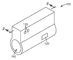
도 1은 본 발명의 휴대용 모니터의 사시도.
< 도 2>
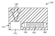
도 2는 도 1의 휴대용 모니터의 일 실시예의 절결도.
<도 3>
도 3은 도 1의 휴대용 모니터의 대안적인 실시예의 절결도.
<도 4>
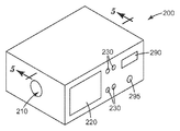
도 4는 본 발명의 대안적인 휴대용 모니터의 사시도.
<도 5>
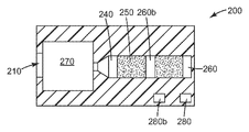
도 5는 도 4의 휴대용 모니터의 일 실시예의 절결도.
<도 6>
도 6은 도 4의 휴대용 모니터의 대안적인 실시예의 절결도.
<도 7>
도 7은 본 발명에 따른 예시적인 광학 판독기의 도면.
예시된 실시예의 하기의 설명에서, 본 발명이 실시될 수 있는 다양한 실시예가 예시로서 도시된 첨부 도면을 참조한다. 이들 실시예가 이용될 수 있고 구조적 변화가 본 발명의 범주로부터 벗어나지 않고서 이루어질 수 있다는 것을 이해하여야 한다. 도면들이 반드시 축척대로 도시된 것은 아니다. 도면들에 사용된 동일한 도면 부호는 동일한 구성요소를 지칭한다. 그러나, 주어진 도면에서 구성요소를 지칭하기 위한 도면 부호의 사용은 동일한 도면 부호로 표시된 다른 도면의 구성요소를 제한하고자 하는 것이 아님을 이해할 것이다.The invention may be more fully understood in view of the following detailed description of various embodiments of the invention in connection with the accompanying drawings.
≪ 1 >
1 is a perspective view of a portable monitor of the present invention.
<FIG. 2>
2 is a cutaway view of one embodiment of the portable monitor of FIG.
3,
3 is a cutaway view of an alternative embodiment of the portable monitor of FIG.
<Fig. 4>
4 is a perspective view of an alternative portable monitor of the present invention.
5,
5 is a cutaway view of one embodiment of the portable monitor of FIG.
6,
6 is a cutaway view of an alternative embodiment of the portable monitor of FIG.
7,
7 is an illustration of an exemplary optical reader in accordance with the present invention.
In the following description of the illustrated embodiments, reference is made to the accompanying drawings in which various embodiments in which the invention may be practiced are shown by way of illustration. It is to be understood that these embodiments may be utilized and structural changes may be made without departing from the scope of the present invention. The drawings are not necessarily drawn to scale. Like reference numerals used in the drawings refer to like elements. It should be understood, however, that the use of reference numerals to designate elements in the given drawings is not intended to limit the elements of the other drawings, which are denoted by the same reference numerals.
공기 정화 호흡기와 같은 공기 정화 시스템의 유효 사용 수명의 종료를 모니터링하고 검출하기 위한 방법 및 장치에 대한 필요성이 존재한다. 때때로 사용 수명 종료 표시기(End of Service Life Indicator) 또는 ESLI로 불리는 그러한 장치는 다양한 환경에서 사용되기에 충분하게 강건하고, 장치의 사용자와 함께 여러 장소로 이동할 수 있기에 충분하게 휴대하기 쉬워야 한다.There is a need for a method and apparatus for monitoring and detecting the end of the useful life of an air purification system, such as an air purification respirator. Such devices, sometimes referred to as End of Service Life Indicators or ESLI, should be robust enough to be used in a variety of environments and easy to carry enough to be able to travel to various locations with the user of the device.
공기 정화 시스템의 유효 사용 수명의 종료를 모니터링하고 검출하기 위한 휴대용 장치가 개시된다. 이들 휴대용 장치는 유기 증기에 대한 노출에 대항하여 보호하도록 설계된 호흡기의 유효 사용 수명의 종료를 모니터링하고 검출하기에 특히 적합하다. 본 명세서에 사용되는 바와 같은 "유기 증기"라는 용어는 사람이 호흡하는 공기 중에 존재할 경우 사람에게 유해할 수 있는 광범위한 휘발성 공기중 유기 화합물을 지칭한다. 유기 증기의 예는 아이소프로판올 및 부탄올과 같은 알코올; 헥산 및 옥탄과 같은 알칸; 벤젠, 톨루엔, 자일렌, 및 스티렌과 같은 방향족 물질; 클로로폼 및 메틸렌 클로라이드와 같은 할로카본; 아세톤 및 메틸 에틸 케톤과 같은 케톤; 테트라하이드로푸란과 같은 에테르; 에틸 아세테이트 및 에톡시에틸 아세테이트와 같은 에스테르; 메틸아크릴레이트와 같은 아크릴레이트; 아세토니트릴과 같은 니트릴; 톨루엔-2,4-다이아이소시아네이트와 같은 아이소시아네이트 등을 포함하지만 이들로 제한되지 않는다. 전형적으로, 유기 증기 호흡기는 유기 증기를 포착하여 유지하기 위한 흡수 매체를 포함한다.A portable device for monitoring and detecting the end of the useful life of an air purification system is disclosed. These portable devices are particularly suitable for monitoring and detecting the end of the useful life of a respirator designed to protect against exposure to organic vapors. The term "organic vapor" as used herein refers to a wide range of volatile organic compounds in air that can be harmful to humans when present in human breathing air. Examples of organic vapors include alcohols such as isopropanol and butanol; Alkanes such as hexane and octane; Aromatic materials such as benzene, toluene, xylene, and styrene; Halocarbons such as chloroform and methylene chloride; Ketones such as acetone and methyl ethyl ketone; Ethers such as tetrahydrofuran; Esters such as ethyl acetate and ethoxy ethyl acetate; Acrylates such as methyl acrylate; Nitriles such as acetonitrile; Isocyanates such as toluene-2,4-diisocyanate and the like, but are not limited to these. Typically, the organic vapor respirator includes an absorbent medium for trapping and retaining organic vapor.
본 발명의 휴대용 장치는 요구 물질, 검출점을 가진 감지 요소, 감지 요소를 위한 판독기, 및 유체 전달 장치를 포함한다. 감지 요소는 요구 물질 내에 또는 요구 물질에 인접하게 위치된다. 휴대용 장치는 감지 요소의 검출점이 필터 카트리지의 사용 수명에 대응하도록 상호관련된다. 일부 실시예에서, 검출점은, 예를 들어 색상 변화와 같은 광학적 변화를 포함한다. 일부 실시예에서, 휴대용 장치는 적어도 요구 물질을 함유하고, 또한 감지 요소를 함유할 수 있는 리셉터클을 포함한다.The portable device of the present invention includes a required material, a sensing element with a detection point, a reader for the sensing element, and a fluid delivery device. The sensing element is located in or adjacent to the required material. The portable device is correlated such that the detection point of the sensing element corresponds to the service life of the filter cartridge. In some embodiments, the detection point includes an optical change such as, for example, a color change. In some embodiments, the portable device includes a receptacle that contains at least the required material and may also contain a sensing element.
매우 다양한 재료가 요구 물질로서 사용하기에 적합할 수 있다. 본 명세서에 사용되는 바와 같이, "요구 물질"이라는 용어는 유기 증기를 흡수할 수 있는 물질을 지칭한다. 일부 실시예에서, 요구 물질은 흡착 재료를 포함한다. 다른 실시예에서, 요구 물질은 층상 필름을 포함한다. 또 다른 실시예에서, 요구 물질은 과립형 또는 모놀리식(monolithic)일 수 있다.A wide variety of materials may be suitable for use as the required material. As used herein, the term "required material" refers to a material that can absorb organic vapors. In some embodiments, the required material includes an adsorbent material. In another embodiment, the required material includes a layered film. In yet another embodiment, the required material may be granular or monolithic.
요구 물질이 흡착 재료를 포함하는 실시예에서, 흡착 재료는 전형적으로 유기 증기를 흡수 또는 흡착할 수 있다. 흡착 재료는 유기 증기 호흡기의 필터 카트리지에 사용되는 흡착 재료와 동일하거나 유사할 수 있다. 적합한 흡착 재료의 예는, 예를 들어 활성탄(activated carbon), 처리된 활성탄, 알루미나, 실리카겔, 호프칼라이트(hopcalite), 분자체(molecular sieve), 금속-유기 골격체(metal-organic framework), 또는 이들의 조합을 포함한다.In embodiments where the desired material includes an adsorbent material, the adsorbent material may typically absorb or adsorb organic vapors. The adsorption material may be the same or similar to the adsorption material used in the filter cartridge of the organic vapor respirator. Examples of suitable adsorbent materials are, for example, activated carbon, treated activated carbon, alumina, silica gel, hopcalite, molecular sieves, metal-organic frameworks, Or combinations thereof.
개시된 장치는 다양한 흡착 매체를 채용할 수 있다. 흡착 매체는 의도된 사용 조건 하에서 존재할 것으로 예상되는 관심 대상의 증기를 흡착할 수 있을 것이다. 흡착 매체는 바람직하게는 그를 통한 공기 또는 다른 기체의 용이한 유동을 허용하기에 충분하게 다공성이며, 미세 분할된 고체(예컨대, 분말, 비드(bead), 플레이크(flake), 과립, 또는 응집체) 또는 다공성 고체(예컨대, 개방 셀형 발포체 또는 다공성 모놀리식 재료)의 형태일 수 있다. 특히 바람직한 흡착 매체 재료는 활성탄; 흡착에 의해 관심 대상의 증기를 제거할 수 있는 알루미나 및 다른 금속 산화물; 아세트산과 같은 산성 용액 또는 수성 수산화나트륨과 같은 알칼리성 용액으로 처리된 점토 및 다른 광물; 분자체 및 다른 제올라이트; 실리카와 같은 다른 무기 흡착제; 및 (예를 들어, 문헌[V. A. Davankov and P. Tsyurupa, Pure and Appl. Chem., vol. 61, pp. 1881-89 (1989)] 및 문헌[L. D. Belyakova, T. I. Schevchenko, V. A. Davankov and M. P. Tsyurupa, Adv. in Colloid and Interface Sci. vol. 25, pp. 249-66, (1986)]에 기술된 바와 같은) "스티로소브(Styrosorb)"로서 알려진 고도로 가교결합된 스티렌계 중합체와 같은 초가교결합된(hypercrosslinked) 시스템을 포함하는 유기 흡착제를 포함한다. 활성탄 및 알루미나가 특히 바람직한 흡착 매체이다. 흡착 매체들의 혼합물이, 예컨대 관심 대상의 증기들의 혼합물을 흡수하도록 채용될 수 있다. 미세 분할된 형태인 경우, 흡착 입자 크기는 크게 변할 수 있고 보통은 의도된 사용 조건에 부분적으로 기초하여 선택될 것이다. 일반적인 지침으로서, 미세 분할된 흡착 매체 입자는 약 4 내지 약 5000 마이크로미터의 평균 직경, 예컨대 약 30 내지 약 1500 마이크로미터의 평균 직경으로 크기가 변할 수 있다. 상이한 크기 범위를 갖는 흡착 매체 입자들의 혼합물이 (예컨대, 흡착 매체 입자들의 이원 혼합물(bimodal mixture), 또는 상류 층 내에 더 큰 흡착 입자를 그리고 하류 층 내에 더 작은 흡착 입자를 채용하는 다층 배열에) 또한 채용될 수도 있다. 미국 특허 제3,971,373호(브라운(Braun) 등), 미국 특허 제4,208,194호(넬슨(Nelson)) 및 미국 특허 제4,948,639호(브루커(Brooker) 등)에 그리고 미국 특허 출원 공개 제2006/0096911 A1호(브레이(Brey) 등)에 기술된 바와 같은, 적합한 결합제(예컨대, 결합 탄소)와 조합되거나 적합한 지지체 상에 또는 그 내에 포획된 흡착 매체가 또한 채용될 수 있다.The disclosed apparatus can employ a variety of adsorptive media. The adsorption medium will be able to adsorb the vapor of interest that is expected to be present under the intended use conditions. The adsorption medium is preferably sufficiently porous to allow easy flow of air or other gas therethrough and is finely divided solids (eg, powders, beads, flakes, granules, or aggregates) or It may be in the form of a porous solid (eg, open cell foam or porous monolithic material). Particularly preferred adsorption media materials include activated carbon; Alumina and other metal oxides capable of removing the vapor of interest by adsorption; Clay and other minerals treated with an acidic solution such as acetic acid or with an alkaline solution such as aqueous sodium hydroxide; Molecular sieves and other zeolites; Other inorganic adsorbents such as silica; And (see, for example, VA Davankov and P. Tsyurupa, Pure and Appl. Chem ., Vol. 61, pp. 1881-89 (1989)) and LD Belyakova, TI Schevchenko, VA Davankov and MP Tsyurupa, Supercrosslinks, such as highly crosslinked styrenic polymers known as "Styrosorb" (as described in Adv. In Colloid and Interface Sci. Vol. 25, pp. 249-66, (1986)). Organic sorbents including hypercrosslinked systems. Activated carbon and alumina are particularly preferred adsorption media. A mixture of adsorption media can be employed, for example, to absorb a mixture of vapors of interest. In the finely divided form, the adsorbed particle size can vary widely and will usually be selected based in part on the intended use conditions. As a general guideline, the finely divided adsorption media particles can vary in size to an average diameter of about 4 to about 5000 micrometers, such as an average diameter of about 30 to about 1500 micrometers. Mixtures of adsorption media particles having different size ranges (eg, in a bimodal mixture of adsorption media particles, or in a multilayer arrangement employing larger adsorption particles in the upstream layer and smaller adsorption particles in the downstream layer) may also be used. It may be employed. US Patent No. 3,971,373 (Braun et al.), US Patent No. 4,208,194 (Nelson) and US Patent No. 4,948,639 (Brooker et al.) And US Patent Application Publication No. 2006/0096911 A1 Adsorption media, as described in (Brey et al.), Combined with a suitable binder (eg, bound carbon) or trapped on or in a suitable support, may also be employed.
매우 다양한 감지 요소가 본 발명의 장치에 사용하기에 적합하다. 일부 실시예에서, 감지 요소는 요구 물질과 동일한 리셉터클 내에 위치된다. 다른 실시예에서, 감지 요소는 리셉터클 내에 위치되지 않고, 요구 물질을 빠져나가는 스트림이 감지 요소에 충돌된다.A wide variety of sensing elements are suitable for use in the device of the present invention. In some embodiments, the sensing element is located in the same receptacle as the desired material. In another embodiment, the sensing element is not located in the receptacle and a stream exiting the required material impinges on the sensing element.
감지 요소는 요구 물질이 노출 조건에서 분석물과 평형을 이룰 때, 예를 들어 (비색 변화, 휘도 변화, 반사된 광의 강도 등에 의해 나타날 수 있는 바와 같이) 그의 광학적 특성들 중 적어도 하나의 변화를 겪음으로써, 분석물에 대해 광학적으로 응답한다.The sensing element undergoes a change in at least one of its optical properties (as may be manifested by colorimetric changes, brightness changes, intensity of reflected light, etc.) when the required material is in equilibrium with the analyte at exposure conditions. Thereby optically responding to the analyte.
감지 요소 또는 감지 요소들의 선택은 사용되는 감지 요소를 위한 판독기의 특성을 비롯한, 다양한 기준에 의존할 것이다. 판독기가 사람의 육안인 경우, 감지 요소는 쉽게 구분가능한 광학적 변화를 표시해야 한다. 그러나, 전자 판독기가 이용되는 경우, 더 복잡하거나 미묘한 광학적 변화가 적합하다.The selection of the sensing element or sensing elements will depend on various criteria, including the characteristics of the reader for the sensing element used. If the reader is the human eye, the sensing element should display an easily discernible optical change. However, when electronic readers are used, more complex or subtle optical changes are suitable.
일부 실시예에서, 감지 요소는 필름이다. 필름은 다수의 층을 가질 수 있고, 비색 필름일 수 있거나(즉, 필름은 유기 분석물에 대한 노출 시에 색상을 변화시킴), 유기 분석물에 대한 노출 시에 몇몇 다른 검출가능한 광학적 변화를 겪을 수 있다. 적합한 센서 필름의 예가 미국 특허 제7,449,146호(라코브(Rakow) 등) 및 미국 특허 출원 공개 제2008/0063575호 및 제2008/0063874호(라코브 등)에 기술되어 있다.In some embodiments, the sensing element is a film. The film may have multiple layers, may be a colorimetric film (ie, the film changes color upon exposure to an organic analyte), or may undergo some other detectable optical change upon exposure to an organic analyte. Can be. Examples of suitable sensor films are described in U.S. Patent No. 7,449,146 (Rakow et al.) And U.S. Patent Application Publication Nos. 2008/0063575 and 2008/0063874 (Lacove et al.).
감지 요소가 다층 필름 구성일 때, 이는 전형적으로 다공성 검출 층, 반-반사 층, 및 반사 층을 포함한다. 다공성 검출 층은 특정 화학 분석물의 존재 시에 변화하는 광학적 두께를 갖는다. 반-반사 층은 외측으로부터 관찰가능하고, 일반적으로 분석물 증기에 의해 투과되지 않는다. 반사 층은 일반적으로 분석물 증기에 대해 투과성이어서, 화학 분석물이 반사 층을 통해 검출 층 내로 통과하여 반-반사 층을 통해 관찰되는 바와 같은 감지 요소 외관의 시각적으로 식별가능한 변화를 일으키기에 충분하게 검출 층의 광학적 두께를 변화시킬 수 있다.When the sensing element is a multilayer film construction, it typically includes a porous detection layer, a semi-reflective layer, and a reflective layer. The porous detection layer has an optical thickness that changes in the presence of certain chemical analytes. The anti-reflective layer is observable from the outside and is generally not permeable by the analyte vapor. The reflective layer is generally permeable to the analyte vapor, so that the chemical analyte passes through the reflective layer into the detection layer and is sufficient to cause a visually discernible change in the appearance of the sensing element as observed through the anti-reflective layer. The optical thickness of the detection layer can be varied.
반사 층은, 예를 들어 약 1 내지 약 500 ㎚의 물리적 두께, 약 0 내지 약 80%의 500 ㎚에서의 광 투과율, 및 약 100 내지 약 20%의 500 ㎚에서의 반사율을 가질 수 있다. 반사 층은 일반적으로 다공성이거나, 패턴화되거나, 불연속적이거나, 반-연속적이거나 또는 달리 충분하게 침투성이어서, 증기가 흡착 매체로부터 반사 층을 통해 검출 층 내로 통과할 수 있도록 한다.The reflective layer can, for example, have a physical thickness of about 1 to about 500 nm, a light transmittance at 500 nm of about 0 to about 80%, and a reflectance at 500 nm of about 100 to about 20%. The reflective layer is generally porous, patterned, discontinuous, semi-continuous or otherwise sufficiently permeable to allow vapor to pass from the adsorption medium through the reflective layer into the detection layer.
검출 층 혼합물은 균질 또는 비균질일 수 있고, 예를 들어 무기 성분들의 혼합물, 유기 성분들의 혼합물, 또는 무기 및 유기 성분들의 혼합물로부터 제조될 수 있다. 성분들의 혼합물로 제조된 검출 층은 분석물 그룹의 개선된 검출을 제공할 수 있다. 검출 층은 바람직하게는 흡착 매체의 증기 흡착 특성과 유사한 증기 흡착 특성을 제공하도록 선택된 일정 범위의 기공 크기 또는 표면적을 갖는다. 적합한 다공성은 미국 특허 제6,573,305 B1호(썬호스트(Thunhorst) 등)에 기술되어 있는 것과 같은, 높은 내부 상 에멀전으로부터 제조된 발포체와 같은 다공성 재료를 사용함으로써 얻어질 수 있다. 다공성은 또한 미공성 재료를 생성하기 위한 이산화탄소 발포(문헌["Macromolecules", 2001, vol. 34, pp. 8792-8801] 참조)를 통해, 또는 중합체 블렌드들의 나노상 분리(문헌["Science", 1999, vol. 283, p. 520] 참조)에 의해 얻어질 수 있다. 일반적으로, 기공 직경은 바람직하게는 원하는 표시기 색상의 피크 파장보다 작다. 예컨대 약 0.5 내지 약 20 ㎚, 0.5 내지 약 10 ㎚, 또는 0.5 내지 약 5 ㎚의 평균 기공 크기를 갖는 나노 크기의 기공이 바람직하다.The detection layer mixture can be homogeneous or heterogeneous and can be prepared, for example, from a mixture of inorganic components, a mixture of organic components, or a mixture of inorganic and organic components. Detection layers made of a mixture of components can provide improved detection of analyte groups. The detection layer preferably has a range of pore sizes or surface areas selected to provide vapor adsorption properties similar to the vapor adsorption properties of the adsorption medium. Suitable porosity can be obtained by using porous materials such as foams made from high internal phase emulsions, such as those described in US Pat. No. 6,573,305 B1 (Thunhorst et al.). Porosity can also be achieved through carbon dioxide foaming (see "Macromolecules", 2001, vol. 34, pp. 8792-8801) to produce microporous materials, or by nanophase separation of polymer blends ("Science", 1999, vol. 283, p. 520). In general, the pore diameter is preferably smaller than the peak wavelength of the desired indicator color. Nano-sized pores having an average pore size of, for example, about 0.5 to about 20 nm, 0.5 to about 10 nm, or 0.5 to about 5 nm are preferred.
대표적인 무기 검출 층 재료는 다공성 실리카, 금속 산화물, 금속 질화물, 금속 산질화물 및 광학 간섭에 의해 색상 또는 비색 변화를 생성하기에 적절한 두께의 투명한 다공성 층으로 형성될 수 있는 다른 무기 재료를 포함한다. 예를 들어, 무기 검출 층 재료는 산화규소, 질화규소, 산질화규소, 산화알루미늄, 산화티타늄, 질화티타늄, 산질화티타늄, 산화주석, 산화지르코늄, 제올라이트 또는 이들의 조합일 수 있다. 다공성 실리카가 그의 강건성 및 습식 에칭 처리와의 상용성으로 인해 특히 바람직한 무기 검출 층 재료이다.Representative inorganic detection layer materials include porous silica, metal oxides, metal nitrides, metal oxynitrides, and other inorganic materials that may be formed into a transparent porous layer of a thickness suitable to produce color or colorimetric changes by optical interference. For example, the inorganic detection layer material may be silicon oxide, silicon nitride, silicon oxynitride, aluminum oxide, titanium oxide, titanium nitride, titanium oxynitride, tin oxide, zirconium oxide, zeolite, or a combination thereof. Porous silica is a particularly preferred inorganic detection layer material because of its robustness and compatibility with wet etching treatment.
다공성 실리카는, 예를 들어 졸-겔 처리 루트를 사용하여 제조될 수 있고 유기 템플릿과 함께 또는 유기 템플릿이 없이 제조될 수 있다. 예시적인 유기 템플릿은 계면활성제, 예컨대 알킬트라이메틸암모늄염, 폴리(에틸렌옥사이드-코-프로필렌 옥사이드) 블록 공중합체 및 당업자에게 명백할 다른 계면활성제 또는 중합체와 같은 음이온성 또는 비이온성 계면활성제를 포함한다. 졸-겔 혼합물은 규산염으로 변환될 수 있고, 유기 템플릿은 제거되어 실리카 내에 미세 기공의 네트워크를 남길 수 있다. 대표적인 다공성 실리카 재료가 문헌[Ogawa et al., Chem. Commun. pp. 1149-1150 (1996)], 문헌[Kresge et al., Nature, Vol. 359, pp. 710-712 (1992)], 문헌[Jia et al., Chemistry Letters, Vol. 33(2), pp. 202-203 (2004)] 및 미국 특허 제5,858,457호(브링커(Brinker) 등)에 기술되어 있다. 다양한 유기 분자가 또한 유기 템플릿으로서 채용될 수 있다. 예를 들어, 포도당 및 만노스와 같은 당이 다공성 규산염을 생성하기 위한 유기 템플릿으로서 사용될 수 있다(문헌[Wei et al, Adv. Mater. 1998, Vol. 10, p. 313 (1998)] 참조). 유기-치환 실록산 또는 유기-비스-실록산이 졸-겔 조성물 내에 포함되어, 미세 기공을 더 소수성으로 만들고 수증기의 흡착을 제한할 수 있다. 플라즈마 화학 기상 증착이 또한 다공성 무기 검출 재료를 생성하기 위해 채용될 수 있다. 이러한 방법은 일반적으로 기체 전구체로부터 플라즈마를 형성함으로써 분석물 검출 층을 형성하는 단계, 비정질 무작위 공유 네트워크 층을 형성하기 위해 기판 상에 플라즈마를 증착시키는 단계, 및 이어서 미공성 비정질 무작위 공유 네트워크 층을 형성하기 위해 비정질 공유 네트워크 층을 가열하는 단계를 포함한다. 그러한 재료의 예는 미국 특허 제6,312,793호(그릴(Grill) 등) 및 미국 특허 출원 공개 제2007/0141580A1호(모세(Moses) 등)에 기술되어 있다.Porous silica can be prepared, for example, using a sol-gel treatment route and can be prepared with or without an organic template. Exemplary organic templates include anionic or nonionic surfactants such as surfactants such as alkyltrimethylammonium salts, poly (ethyleneoxide-co-propylene oxide) block copolymers and other surfactants or polymers that will be apparent to those skilled in the art. The sol-gel mixture can be converted to a silicate and the organic template can be removed leaving a network of micropores in the silica. Representative porous silica materials are described in Ogawa et al., Chem. Commun . pp. 1149-1150 (1996), Kresge et al., Nature , Vol. 359, pp. 710-712 (1992), Jia et al., Chemistry Letters, Vol. 33 (2), pp. 202-203 (2004) and US Pat. No. 5,858,457 (Brinker et al.). Various organic molecules can also be employed as the organic template. For example, sugars such as glucose and mannose can be used as organic templates for producing porous silicates (see Wei et al, Adv. Mater. 1998, Vol. 10, p. 313 (1998)). Organo-substituted siloxanes or organo- bis- siloxanes can be included in the sol-gel composition to make the micropores more hydrophobic and limit the adsorption of water vapor. Plasma chemical vapor deposition may also be employed to create the porous inorganic detection material. This method generally comprises forming an analyte detection layer by forming a plasma from a gaseous precursor, depositing a plasma on the substrate to form an amorphous random shared network layer, and then forming a microporous amorphous random shared network layer. Heating the amorphous shared network layer. Examples of such materials are described in US Pat. No. 6,312,793 (Grill et al.) And US Patent Application Publication No. 2007 / 0141580A1 (Moses et al.).
대표적인 유기 검출 층 재료는 소수성 아크릴레이트 및 메타크릴레이트, 2작용성 단량체, 비닐 단량체, 탄화수소 단량체(올레핀), 실란 단량체, 플루오르화 단량체, 하이드록실화 단량체, 아크릴아미드, 무수물, 알데히드-작용화 단량체, 아민- 또는 아민염-작용화 단량체, 산-작용화 단량체, 에폭사이드-작용화 단량체 및 이들의 혼합물 또는 조합을 포함하는 단량체의 부류로부터 제조되거나 제조가능한 중합체, (블록 공중합체를 포함하는) 공중합체, 및 이들의 혼합물을 포함한다. 미국 특허 출원 공개 제2004/0184948호는 그러한 단량체들의 광범위한 목록을 포함하고, 추가의 상세 사항에 대해서는 이를 참조한다. 전술된 고유 미공성을 갖는 중합체(polymer having intrinsic microporosity, PIM)가 특히 바람직한 검출 매체를 제공한다. PIM은 전형적으로 미공성 고체를 형성하는 비네트워크 중합체이다. 전형적으로 높은 강성 및 뒤틀린 분자 구조로 인해, PIM은 공간을 효율적으로 충전할 수 없어서, 개시된 미공성 구조를 제공한다. 적합한 PIM은 문헌["Polymers of intrinsic microporosity (PIMs): robust, solution-processable, organic microporous materials," Budd et al., Chem. Commun., 2004, pp. 230-231]에 개시된 중합체를 포함하지만 이로 제한되지 않는다. 추가의 PIM은 문헌[Budd et al., J. Mater. Chem., 2005, 15, pp. 1977-1986], 문헌[McKeown et al., Chem. Eur. J. 2005, 11, No. 9, 2610-2620] 및 PCT 출원 공개 WO 2005/012397 A2호(맥권(McKeown) 등)에 개시되어 있다.Representative organic detection layer materials include hydrophobic acrylates and methacrylates, difunctional monomers, vinyl monomers, hydrocarbon monomers (olefins), silane monomers, fluorinated monomers, hydroxylated monomers, acrylamides, anhydrides, aldehyde-functionalized monomers. , Polymers prepared or preparable from the class of monomers, including amine- or amine salt-functionalized monomers, acid-functionalized monomers, epoxide-functionalized monomers and mixtures or combinations thereof, including block copolymers Copolymers, and mixtures thereof. US Patent Application Publication No. 2004/0184948 contains an extensive list of such monomers, see further for further details. The polymer having intrinsic microporosity (PIM) described above provides a particularly preferred detection medium. PIM is typically a nonnetworked polymer that forms a microporous solid. Due to the typically high stiffness and twisted molecular structure, the PIM cannot fill the space efficiently, providing the disclosed microporous structure. Suitable PIMs are described in "Polymers of intrinsic microporosity (PIMs): robust, solution-processable, organic microporous materials," Budd et al., Chem. Commun. , 2004, pp. 230-231, including but not limited to polymers. Additional PIMs are described by Buddha et al., J. Mater. Chem. , 2005, 15, pp. 1977-1986, McKeown et al., Chem. Eur. J. 2005, 11, No. 9, 2610-2620 and PCT Application Publication WO 2005/012397 A2 (McKeown et al.).
유기 검출 층 내의 하나 이상의 중합체는 적어도 부분적으로 가교결합될 수 있다. 가교결합은 기계적 안정성 및 소정의 분석물에 대한 감도를 증가시킬 수 있기 때문에 일부 실시예에서 바람직할 수 있다. 가교결합은 하나 이상의 다작용성 단량체를 검출 층 내로 혼입함으로써, 검출 층을 예컨대 전자 빔 또는 감마 선 처리를 가함으로써, 검출 층 내에 배위 화합물 또는 이온성 화합물을 첨가하거나 형성함으로써, 또는 검출 층 내에 수소 결합을 형성함으로써 달성될 수 있다. 예시적인 일 실시예에서, 가교결합은 이후에 가교결합된 시스템으로부터 추출되어 다공성 검출 층을 생성할 수 있는 포로겐(porogen)의 존재 하에서 수행된다. 적합한 포로겐은 노말 알칸(예컨대, 데칸) 또는 방향족 물질(예컨대, 벤젠 또는 톨루엔)과 같은 불활성 유기 분자를 포함하지만 이로 제한되지 않는다. 다른 가교결합된 중합체는 전술된 고도로 가교결합된 스티렌계 중합체를 포함한다.One or more polymers in the organic detection layer may be at least partially crosslinked. Crosslinking may be desirable in some embodiments because it can increase mechanical stability and sensitivity to certain analytes. Crosslinking involves the incorporation of one or more multifunctional monomers into the detection layer, the addition of a coordination compound or an ionic compound in the detection layer, for example by applying an electron beam or gamma ray treatment, or hydrogen bonding within the detection layer. It can be achieved by forming a. In one exemplary embodiment, crosslinking is performed in the presence of a porogen that can then be extracted from the crosslinked system to produce a porous detection layer. Suitable porogens include, but are not limited to, inert organic molecules such as normal alkanes (eg decane) or aromatics (eg benzene or toluene). Other crosslinked polymers include the highly crosslinked styrenic polymers described above.
필요할 경우, 검출 층 재료는 그의 표면 특성 또는 흡착 특성을 개질시키도록 처리될 수 있다. 다양한 그러한 처리가, 예컨대 무기 검출 층의 미세 기공을 적합한 유기실란 화합물에 노출시킴으로써 채용될 수 있다. 검출 매체는 또한 또는 그 대신에 부분 반사 또는 반사 층과 검출 층 사이의 접착을 증진시키기 위해 적합한 접착 증진 재료(예컨대, 티타늄 또는 다른 적합한 금속으로 제조된 결속 층)로 처리될 수 있다. 그러한 처리는 또한 검출 매체에 대한 접착을 증진시키기 위해 부분 반사 또는 반사 층에 적용될 수 있다.If desired, the detection layer material can be treated to modify its surface or adsorption properties. Various such treatments can be employed, for example, by exposing the micropores of the inorganic detection layer to a suitable organosilane compound. The detection medium may also or instead be treated with a suitable adhesion enhancing material (eg, a binding layer made of titanium or other suitable metal) to promote adhesion between the partially reflective or reflective layer and the detection layer. Such treatment may also be applied to the partially reflective or reflective layer to promote adhesion to the detection medium.
많은 응용에 대해, 검출 층 재료는 바람직하게는 소수성이다. 이는 수증기(또는 액체 물)가 검출 층의 광학 두께의 변화를 일으켜서 분석물의 검출, 예를 들어 유기 용매 증기의 검출을 방해할 가능성을 감소시킬 것이다. 검출 층은 단일 층으로부터 또는 둘 이상의 하위 층으로부터 제조될 수 있다.For many applications, the detection layer material is preferably hydrophobic. This will reduce the likelihood that water vapor (or liquid water) will cause a change in the optical thickness of the detection layer to interfere with the detection of the analyte, for example the detection of organic solvent vapors. The detection layer can be prepared from a single layer or from two or more sublayers.
감지 요소는 또한 2009년 10월 23일자로 출원된 발명의 명칭이 "불활성 폐색 층을 갖는 패턴화된 화학 센서(Patterned Chemical Sensor Having Inert Occluding Layer)"인 대리인 문서 번호 65867US002에 기술되어 있는 것과 같은 패턴화된 화학 센서일 수 있다. 이들 패턴화된 센서는 검출 층을 포함하는 필름 본체 및 필름 본체에 접합되어 검출 층의 일부분을 폐색하는 폐색 층을 포함하는 필름을 포함한다. 검출 층은 유기 화학 물질에 응답하는데, 즉 검출 층은 유기 화학 물질에 대한 노출 시에 색상을 변화시킨다. 폐색 층은 검출되어야 하는 화학 물질이 폐색 영역에 접근하여 색상 변화를 일으키는 것을 방지한다. 이러한 배열의 순 효과는 단일 필름 본체 내에서, 유기 화학 물질에 대한 노출 시에, 검출 층의 "오래된" 색상(즉, 초기 색상 상태) 및 "새로운" 색상(즉, 검출 층의 변화된 색상 상태)이 나란히 존재하여, 사용자가 변화가 발생했는지를 용이하게 결정하도록 허용하는 것이다.The sensing element is also a pattern as described in Agent Document No. 65867US002 entitled “Patterned Chemical Sensor Having Inert Occluding Layer”, filed October 23, 2009. It may be a chemical chemical sensor. These patterned sensors include a film body including a detection layer and a film including a blocking layer bonded to the film body to block a portion of the detection layer. The detection layer responds to the organic chemical, ie the detection layer changes color upon exposure to the organic chemical. The occlusion layer prevents the chemical to be detected from approaching the occlusion area and causing color change. The net effect of this arrangement is that within the single film body, upon exposure to organic chemicals, the "old" color (ie, initial color state) and "new" color (ie, changed color state of the detection layer) of the detection layer. This is present alongside, allowing the user to easily determine if a change has occurred.
다양한 장치가 변화에 대해 감지 요소를 관찰하기 위한 판독기로서 사용될 수 있다. 판독 장치의 선택은, 예를 들어 모니터의 사용의 용이성, 모니터의 비용, 모니터의 휴대성, 모니터의 강건성, (시각적 및 청각적 신호와 같은) 다수의 신호를 제공하기 위한 모니터에 대한 필요성 등과 같은 다양한 인자에 의존할 수 있다.Various devices can be used as readers to observe the sensing elements for changes. The choice of a reading device may include, for example, the ease of use of the monitor, the cost of the monitor, the portability of the monitor, the robustness of the monitor, the need for a monitor to provide multiple signals (such as visual and audio signals), and the like. Can depend on various factors.
일부 실시예에서, 감지 요소를 위한 판독기는 사람의 눈이고, 감지 요소의 모니터링은 색상 변화와 같은 감지 요소 내의 시각적 변화를 관찰하기 위한 시각적 관찰에 의해 행해진다. 이러한 방식으로, 사용자 또는 사용자 그룹이 그들의 호흡기 마스크 또는 그들의 호흡기 마스크 내의 필터 카트리지의 잔여 사용 수명을 쉽게 모니터링할 수 있다. 시각적 모니터링은 추가의 장비, 전원, 또는 정교한 구성요소를 요구하지 않는, 매우 간단하고 저렴한 모니터링 방법이다.In some embodiments, the reader for the sensing element is the human eye, and the monitoring of the sensing element is done by visual observation to observe the visual change in the sensing element, such as color change. In this way, the user or group of users can easily monitor the remaining service life of the filter cartridge in their respirator mask or in their respirator mask. Visual monitoring is a very simple and inexpensive method of monitoring that does not require additional equipment, power, or sophisticated components.
다른 실시예에서, 전자 광학 판독기가 변화를 검출하기 위해 감지 요소를 모니터링하도록 사용될 수 있다. 전자 시스템을 사용하는 것의 이점은 감지 요소를 판독하는 더 높은 정확도를 포함하고, 모니터는 다수의 신호를 제공할 수 있다. 예를 들어, 전자 판독기가 감지 요소 내의 변화를 검출한 때, 광이 환경 내의 사용자에 대한 경고로서 점등될 수 있고, 버저 또는 경적과 같은 청각적 신호가 발생될 수 있으며, 또는 전자 신호가 환경 내의 사용자가 보유한 전자 수신기로 송신될 수 있다.In another embodiment, an electro-optical reader can be used to monitor the sensing element to detect a change. Advantages of using electronic systems include higher accuracy of reading sensing elements, and the monitor can provide multiple signals. For example, when the electronic reader detects a change in the sensing element, light may be lit as a warning to the user in the environment, an acoustic signal such as a buzzer or horn may be generated, or the electronic signal may be in the environment. Can be sent to the electronic receiver held by the user.
적합한 전자 광학 판독기 시스템의 예가, 예를 들어 2010년 4월 2일자로 출원된 발명의 명칭이 "광학 분석물 센서 및 광학 판독기를 포함하는 필터 시스템(Filter Systems Including Optical Analyte Sensors And Optical Readers)"인 대리인 문서 번호 66214US002에 기술되어 있다. 예시적인 광학 판독기가 도 7에 도시되어 있으며 이하에서 기술된다. 전형적으로, 적합한 광학 판독기는 적어도 하나의 광원 및 적어도 하나의 검출기를 포함한다. 광학 판독기는 적어도 하나의 광원에 의해 방출된 광의 적어도 일부가 감지 요소로부터 반사되어 적어도 하나의 검출기에 의해 포착되도록 구성될 수 있다.An example of a suitable electro-optical reader system is, for example, the file name "Filter Systems Including Optical Analyte Sensors And Optical Readers" filed April 2, 2010. Agent document number 66214US002. An exemplary optical reader is shown in FIG. 7 and described below. Typically, a suitable optical reader includes at least one light source and at least one detector. The optical reader may be configured such that at least some of the light emitted by the at least one light source is reflected from the sensing element and captured by the at least one detector.
하나 이상의 광원은 다양한 광원 중 임의의 것을 포함할 수 있다. 예를 들어, 발광 다이오드(light-emitting diode, LED)가 사용될 수 있다. 소정 실시예에서, 하나 이상의 광원은 하나 이상의 상대적으로 광대역인 광원(예컨대, 백색 광원)을 포함할 수 있다. 다른 실시예에서, 광원은 특정(예컨대, 상대적으로 좁은) 파장 범위 내에서, 그 범위 내의 특정 파장에서 피크를 갖는 광을 방출하는 하나 이상의 협대역 광원(예컨대, LED)을 포함할 수 있다. 다양한 실시예에서, 이러한 협대역 광원은 최대 약 50 ㎚, 최대 약 40 ㎚, 또는 최대 약 25 ㎚의 반-전력 대역폭(half-power bandwidth)을 특징으로 할 수 있다. 사용될 수 있는 예시적인 LED는 명칭 OVLBx4C7로 미국 텍사스주 캐롤튼 소재의 옵텍(Optek)으로부터 입수가능한 것, 및 오스람(Osram)으로부터의 LS T676, LA T676, LO T676, LY T676 시리즈와 같은 표면 실장(surface mount) LED를 포함한다.One or more light sources may include any of a variety of light sources. For example, a light-emitting diode (LED) can be used. In certain embodiments, one or more light sources may include one or more relatively broadband light sources (eg, white light sources). In other embodiments, the light source may include one or more narrowband light sources (eg, LEDs) that emit light with peaks at specific wavelengths within a particular (eg, relatively narrow) wavelength range. In various embodiments, such narrowband light sources can be characterized by a half-power bandwidth of up to about 50 nm, up to about 40 nm, or up to about 25 nm. Exemplary LEDs that can be used are the name OVLBx4C7 available from Optek, Carrollton, TX, USA, and surface mounts such as the LS T676, LA T676, LO T676, LY T676 series from Osram. surface mount) LEDs.
전자 광학 판독기에 사용하기에 적합한 검출기는, 예를 들어 광전증배관, 광전지, 광다이오드, 광트랜지스터, 전하 결합 소자 등과 같은 광검출기를 포함하는, 그에 입사하는 광량을 측정할 수 있는 다양한 장치 중 임의의 것을 포함할 수 있다. 적합한 검출기가 검출된 광량(예컨대, 감지 요소로부터 수신되는 반사된 광의 강도 또는 세기)에 관련되며 추가로 처리될 수 있는 신호(예컨대, 전압, 전류 등)를 제공하도록 역할할 수 있다. 일부 실시예에서, 하나 이상의 검출기가 특정(예를 들어, 상대적으로 좁은) 파장 범위의 광을 검출할 수 있다. 다른 실시예에서, 하나 이상의 검출기는 상대적으로 넓은 범위의 파장에 걸쳐 광을 검출할 수 있는 광대역 검출기를 포함할 수 있다. 다양한 실시예에서, 그러한 광대역 검출기는 약 150 ㎚ 폭, 250 ㎚ 폭, 또는 500 ㎚ 폭 이상의 파장 범위에 걸쳐 광을 검출할 수 있다. 사용될 수 있는 예시적인 검출기는 명칭 SFH 2430으로 독일 로젠스버그 소재의 오스람으로부터 입수가능한 광다이오드를 포함한다.Suitable detectors for use in electro-optical readers include any of a variety of devices capable of measuring the amount of light incident thereon, including, for example, photodetectors such as photomultipliers, photovoltaic cells, photodiodes, phototransistors, charge coupled devices, and the like. It may include that of. Suitable detectors may serve to provide a signal (eg, voltage, current, etc.) that is related to the amount of light detected (eg, intensity or intensity of reflected light received from the sensing element) and may be further processed. In some embodiments, one or more detectors can detect light in a particular (eg, relatively narrow) wavelength range. In other embodiments, one or more detectors may include a wideband detector capable of detecting light over a relatively wide range of wavelengths. In various embodiments, such a wideband detector may detect light over a wavelength range of about 150 nm wide, 250 nm wide, or 500 nm wide or more. Exemplary detectors that may be used include photodiodes available from Osram, Rosensburg, Germany under the name SFH 2430.
다수의 광원이 광학 판독기의 일부로서 사용될 수 있다. 예를 들어, 제1 및 제2 광원이 각각 제1 및 제2 스펙트럼(또는 파장) 범위 및 제1 및 제2 피크 파장을 특징으로 할 수 있다. 제1 스펙트럼 범위는 제1 스펙트럼 범위와 상이할 수 있으며 제1 및 제2 광원은 상이한 피크 파장의 광을 방출할 수 있다. 그러한 설계에서, 상이한 광원들이 공통 검출기에 이웃하여 장착될 수 있다.Multiple light sources can be used as part of the optical reader. For example, the first and second light sources may be characterized by a first and second spectrum (or wavelength) range and a first and second peak wavelength, respectively. The first spectral range can be different from the first spectral range and the first and second light sources can emit light of different peak wavelengths. In such a design, different light sources can be mounted adjacent to the common detector.
제1 및 제2 광원은 그들의 스펙트럼이 상이한 파장 범위(A 및 B) 및 상이한 피크 파장을 특징으로 하도록 선택될 수 있다. 그러한 실시예에서, 단일(예컨대, 광대역) 광검출기가 검출기로서 사용될 수 있다. 다수의 파장 범위에서 광학 분석물 센서로부터 반사되는 광을 모니터링하는 것은 상당한 이점을 제공할 수 있다. 그러한 검출의 다양한 상세 사항 및 원리는, 예를 들어 공동 소유의 미국 가특허 출원 제61/164,496호(헐틴(Hulteen) 등)에 기재되어 있다.The first and second light sources can be chosen such that their spectra are characterized by different wavelength ranges (A and B) and different peak wavelengths. In such embodiments, a single (eg, broadband) photodetector can be used as the detector. Monitoring light reflected from optical analyte sensors in multiple wavelength ranges can provide significant advantages. Various details and principles of such detection are described, for example, in co-owned US Provisional Patent Application 61 / 164,496 (Hulteen et al.).
대안적으로, 광학 판독기는 2개의 광원 및 2개의 검출기를 포함할 수 있다. 그러한 광학 판독기는 또한 적어도 하나의 광원에 의해 방출된 광의 적어도 일부가 감지 요소로부터 반사되어 검출기에 의해 포착되도록 구성될 수 있다. 광원들은 각각 다른 광원에 의해 방출되는 것과 상이한 피크 파장을 가진 상이한 파장 범위 내의 광을 방출할 수 있다. 각각의 광원은 대응하는 광원에 의해 방출되는 특정 파장 범위 내의 광을 검출하도록 설계된 광검출기와 조합하여 사용될 수 있다.Alternatively, the optical reader may include two light sources and two detectors. Such optical reader may also be configured such that at least some of the light emitted by the at least one light source is reflected from the sensing element and captured by the detector. The light sources can emit light in different wavelength ranges, each with a different peak wavelength than that emitted by the other light sources. Each light source can be used in combination with a photodetector designed to detect light within a particular wavelength range emitted by the corresponding light source.
전자 광학 판독기는 추가의 구성요소를 포함할 수 있다. 예를 들어, 전자 광학 판독기는 배터리, 하나 이상의 광원 또는 모니터 스크린과 같은 경보 장치, 및 액추에이터를 추가로 포함할 수 있다. 사용자가 광학 판독기에 의한 감지 요소의 호출을 개시하도록 액추에이터를 트리거링할 수 있다. 광학 판독기는 직렬 인터페이스에 의해 컴퓨터와 같은 다른 전자 장치에 연결될 수 있다. 따라서, 광학 판독기는 다양한 정보를, 예를 들어 디스플레이에 전달할 수 있다.The electro-optical reader may include additional components. For example, the electro-optical reader may further include a battery, an alarm device such as one or more light sources or a monitor screen, and an actuator. The user can trigger the actuator to initiate a call of the sensing element by the optical reader. The optical reader may be connected to another electronic device such as a computer by a serial interface. Thus, the optical reader can convey various information, for example to a display.
매우 다양한 장치가 그들이 모니터링 장치를 통해 유량을 신뢰할 수 있게 제어할 수 있는 한 유체 전달 장치로서 사용될 수 있다. 유용한 유체 전달 장치들 중에, 팬 및 펌프가 있다. 팬 또는 펌프는 전형적으로 전동식이지만, 일부 실시예에서, 수동식 펌프와 같은 수동식 장치가 적합할 수 있다.A wide variety of devices can be used as the fluid delivery device as long as they can reliably control the flow rate through the monitoring device. Among the useful fluid delivery devices are fans and pumps. The fan or pump is typically electric, but in some embodiments, a manual device, such as a hand pump, may be suitable.
매우 다양한 적합한 팬 및 펌프가 구매가능하다. 하나의 적합한 부류의 펌프는 미국 뉴저지주 트렌톤 소재의 케이엔에프 노이버거, 인크.(KNF Neuberger, Inc.)로부터 상표명 NMP 05 S(브러시형 모터를 구비함), NMP 09 M(비철 코어 모터를 구비함), 및 NMP 015 B(무브러시 DC 모터를 구비함)로 구매가능한 것들과 같은 마이크로 다이어프램 기체 샘플링 펌프이다. 다른 적합한 팬 및 펌프가 공기 정화 분야에 공지되어 있다.A wide variety of suitable fans and pumps are commercially available. One suitable class of pumps includes the NMP 05 S (with brushed motors), NMP 09 M (non-ferrous core motors) from KNF Neuberger, Inc., Trenton, NJ. And a diaphragm gas sampling pump such as those available with NMP 015 B (with a brushless DC motor). Other suitable fans and pumps are known in the field of air purification.
장치는 리셉터클을 추가로 포함할 수 있다. 리셉터클은 요구 물질을 함유할 수 있거나, 이는 요구 물질 및 적어도 하나의 감지 요소를 함유할 수 있다. 매우 다양한 리셉터클이 가능하다. 리셉터클은, 예를 들어 장치의 전체 형상 및 설계에 따라 튜브, 카트리지, 박스, 또는 디스크일 수 있다.The apparatus may further comprise a receptacle. The receptacle may contain the required material or it may contain the required material and at least one sensing element. A wide variety of receptacles are possible. The receptacle can be, for example, a tube, cartridge, box, or disk, depending on the overall shape and design of the device.
일부 실시예에서, 리셉터클은 튜브이다. 튜브는 유리 또는 플라스틱으로 제조될 수 있고, 감지 요소가 리셉터클 내에 포함되는 경우, 튜브가 투명한 것이 바람직할 수 있다.In some embodiments, the receptacle is a tube. The tube may be made of glass or plastic, and if the sensing element is included in the receptacle, it may be desirable for the tube to be transparent.
전체 모니터링 장치는 케이스 내에 수용될 수 있다. 케이스는 요구 물질을 함유하는 리셉터클을 보유할 수 있다. 리셉터클은 또한 적어도 하나의 감지 요소를 함유할 수 있거나, 케이스 내의 리셉터클과 유체 연통하는 감지 요소가 있을 수 있다. 케이스는 또한 유체 전달 장치를 보유할 수 있다. 상기 논의된 바와 같이, 유체 전달 장치는 팬 또는 펌프일 수 있고, 배터리와 같은 전원에 의해 급전될 수 있거나, 이는 수동식일 수 있다. 케이스는 또한 감지 요소를 위한 판독기를 포함할 수 있다. 일부 실시예에서, 감지 요소가 사람의 눈에 의해 판독되는 경우, 판독기는 윈도우 또는 다른 오리피스일 수 있고, 이를 통해 감지 요소가 모니터링될 수 있다. 윈도우 또는 다른 오리피스는 개방부일 수 있거나, 이는 투명 커버에 의해 덮일 수 있다. 감지 요소가 전자식으로 모니터링되는 다른 실시예에서, 판독기는, 예를 들어 디스플레이 스크린 또는 다른 전자 데이터 전달 수단과 상호작용할 수 있다.The entire monitoring device can be housed in the case. The case may have a receptacle containing the required material. The receptacle may also contain at least one sensing element or there may be a sensing element in fluid communication with the receptacle in the case. The case may also hold a fluid delivery device. As discussed above, the fluid delivery device may be a fan or a pump and may be powered by a power source such as a battery, or it may be manual. The case may also include a reader for the sensing element. In some embodiments, when the sensing element is read by the human eye, the reader may be a window or other orifice through which the sensing element may be monitored. The window or other orifice may be an opening or it may be covered by a transparent cover. In another embodiment in which the sensing element is monitored electronically, the reader may interact with, for example, a display screen or other electronic data transfer means.
본 발명의 모니터의 몇몇 실시예가 도면에 제시되어 있다. 도 1은 본 발명의 예시적인 휴대용 모니터의 사시도를 도시한다. 도 1에서, 휴대용 모니터(100)는 유체 입구(110), 판독기 윈도우(120) 및 제어 버튼(130)을 포함한다. 유체 입구(110)는 간단한 오리피스일 수 있거나, 이는 (도시 안된) 커버를 가진 오리피스일 수 있고, 커버는 스크린 또는 복수의 보다 작은 오리피스이거나 이를 포함한다. 커버는, 존재할 경우, 탈착가능할 수 있다. 이러한 비교적 간단한 휴대용 모니터에서, 모니터링되는 기체가 유체 입구(110)로 진입하고, 사용자가 판독기 윈도우(120)를 통해 감지 요소를 관찰함으로써 (도시 안된) 감지 요소를 모니터링할 수 있다. 판독기 윈도우(120)의 위치 및 크기는 감지 요소의 용이한 관찰을 허용하도록 상이한 실시예들에서 변경될 수 있다는 것에 유의한다. 판독기 윈도우(120)는 간단히 개구일 수 있거나, 이는 유리 또는 중합체 재료(예를 들어, 폴리카르보네이트 또는 폴리아크릴레이트)와 같은 투명 커버를 가질 수 있다. 제어 버튼(130)은 (도시 안된) 휴대용 모니터 내의 유체 전달 장치를 제어한다. 유체 전달 장치는 팬 또는 펌프일 수 있고, 전형적으로 이는 펌프이다. 2개의 제어 버튼이 도 1에 도시되어 있지만, 더 적거나 더 많은 제어 버튼 그리고 제어 스위치 또는 심지어 다이얼이 존재할 수 있다. 도 1에 도시된 실시예에서, 2개의 제어 버튼은 유체 전달 장치를 켜고 끌 수 있고, 그리고/또는 유체가 휴대용 모니터를 통과하는 속도를 제어할 수 있다.Some embodiments of the monitor of the present invention are shown in the drawings. 1 shows a perspective view of an exemplary portable monitor of the present invention. In FIG. 1, the
도 2는 도 1에 도시된 평면 2를 따라 절결된, 도 1의 휴대용 모니터의 절결도이다. 이러한 실시예에서, 유체 입구(110) 내로 통과하는 기체는 요구 물질(150) 및 감지 요소(160)를 함유하는 리셉터클(140) 내로 통과한다. 기체는, 이러한 실시예에서 펌프이며 제어 버튼(130)에 의해 제어되는 유체 전달 장치(170)에 의해 리셉터클을 통해 흡인된다.FIG. 2 is a cutaway view of the portable monitor of FIG. 1, cut along plane 2 shown in FIG. 1. In this embodiment, gas passing into the
도 3은 도 1에 도시된 평면 2를 따라 절결된, 도 1의 휴대용 모니터의 대안적인 실시예의 절결도이다. 이러한 실시예에서, 유체 입구(110) 내로 통과한 기체는 유체 전달 장치(170) 내로 통과하고, 요구 물질(150) 및 감지 요소(160)를 함유하는 리셉터클(140)로 진입한다. 이러한 실시예에서, 기체는, 이러한 실시예에서 펌프이며 제어 버튼(130)에 의해 제어되는 유체 전달 장치(170)에 의해 리셉터클을 통해 밀려나간다.3 is a cutaway view of an alternative embodiment of the portable monitor of FIG. 1, cut along plane 2 shown in FIG. 1. In this embodiment, the gas passing into the
도 4는 본 발명의 상이한 예시적인 휴대용 모니터의 사시도를 도시한다. 도 4에서, 휴대용 모니터(200)는 유체 입구(210), 판독기 스크린(220), 제어 버튼(230), 스피커(290), 및 라이트(295)를 포함한다. 이러한 더 복잡한 휴대용 모니터에서, 모니터링되는 기체는 유체 입구(110)로 진입하고, 사용자는 다양한 메시지 및 정보를 포함할 수 있는 전자 스크린인 판독기 스크린(220)을 관찰함으로써 (도시 안된) 감지 요소를 모니터링할 수 있다. 예를 들어, 판독기 스크린은 모니터의 상태(켜짐 또는 꺼짐); 사용된 시간; 사용 수명의 종료 이전까지 남은 시간 등과 같은 정보를 전송할 수 있다. 제어 버튼(230)은 휴대용 모니터(100) 내에서와 같이 유체 전달 장치를 제어할 수 있으며 판독기 스크린(220)의 기능을 제어할 수 있다. 스피커(290) 및 라이트(295)는 휴대용 모니터와 함께 채용될 수 있는 선택적인 추가의 경고 장치이다. 스피커는 사용자에게 휴대용 모니터의 상태의 변화 또는 사용 수명의 종료가 도달되었거나 임박한 것의 경보를 발생시키기 위해 청각적 신호 또는 메시지를 방송할 수 있다. 유사하게, 라이트는 휴대용 모니터가 점검되어야 함을 사용자에게 알리기 위해 추가의 표시기로서 켜지거나 점등되기 시작할 수 있다.4 shows a perspective view of different exemplary portable monitors of the present invention. In FIG. 4, the
도 5는 도 4에 도시된 평면 5를 따라 절결된, 도 4의 휴대용 모니터의 일 실시예의 절결도이다. 기체가 기체 입구(210)를 통해 휴대용 모니터로 진입하고, 유체 전달 장치(펌프)(270)로 진입하고, 요구 물질(250) 및 감지 요소(260)를 함유하는 리셉터클(240)로 진입한다. 감지 요소(260)는 판독기(280)에 의해 모니터링될 수 있다. 판독기(280)는 감지 요소(260) 내의 변화를 검출하기 위한 전자 판독기이다. 판독기(280)는 (도시되지는 않았지만, 도 4에서 요소(220)로서 도시되어 있는) 판독기 스크린으로 출력을 보낸다.5 is a cutaway view of one embodiment of the portable monitor of FIG. 4, cut along plane 5 shown in FIG. 4. Gas enters the portable monitor through
도 6은 도 4에 도시된 평면 5를 따라 절결된, 도 4의 휴대용 모니터의 대안적인 실시예의 절결도이다. 상기 열거된 요소들 모두와, 추가의 감지 요소(260b) 및 추가의 판독기(280b)가 존재한다. 추가의 감지 요소 및 판독기는 추가의 유기 증기를 감지하거나, 추가의 감지 출력을 제공하거나, 이 둘 모두를 하는 능력을 휴대용 모니터에 제공할 수 있다. 감지 요소(260b)는 감지 요소(260)와 동일하거나, 유사하거나, 상이할 수 있다. 유사하게, 감지 요소(260b)의 특성에 따라, 판독기(280b)는 판독기(280)와 동일하거나, 유사하거나, 상이할 수 있다.6 is a cutaway view of an alternative embodiment of the portable monitor of FIG. 4, cut along plane 5 shown in FIG. 4. With all of the above listed elements, there is an
도 7은 본 발명의 모니터와 함께 사용하기에 적합한 예시적인 광학 판독기(300)를 도시한다. 광학 판독기(300)는 적어도 하나의 광원(여기서, 312 및 314) 및 적어도 하나의 검출기(320)를 포함한다. 하나 이상의 광원(예컨대, 312 및 314) 및 하나 이상의 검출기(320)가 동일한 지지체(350) 상에 장착될 수 있다. 광학 판독기(300)는 본 발명에 따른 모니터의 케이스에 부착되도록 구성될 수 있다. 감지 요소(330)는 디스크로서 도시되어 있지만, 임의의 적합한 형상일 수 있으며, (도시 안된) 리셉터클 내에 포함될 수 있거나 리셉터클로부터의 진출 스트림이 감지 요소(330)에 충돌하도록 위치될 수 있다. 적어도 하나의 광원(312, 314)에 의해 방출되는 광(312a, 314a)의 적어도 일부가 감지 요소(330)로부터 반사되어 적어도 하나의 검출기(320)에 의해 포착된다.7 illustrates an exemplary
모니터링 장치를 필터 카트리지의 유효 사용 수명에 상호관련시키기 위한 방법은 모니터링 장치를 제공하는 단계 및 모니터링 장치의 사용 수명을 필터 카트리지의 사용 수명에 대응하도록 보정하는 단계를 포함한다. 적합한 모니터링 장치가 이하 기술된다. 모니터링 장치는 필터 카트리지를 모사하지만, 필터 카트리지의 유효 사용 수명이 언제 종료되는지를 결정하기 위해 모니터링될 수 있다. 모니터링 장치를 모니터링하고 필터 카트리지의 사용 수명의 종료에 모니터링 장치의 센서 응답을 상호관련시킴으로써, 사용자는 필터 카트리지의 유효 사용 수명을 결정할 수 있다.A method for correlating a monitoring device to an effective service life of a filter cartridge includes providing a monitoring device and correcting the service life of the monitoring device to correspond to the service life of the filter cartridge. Suitable monitoring devices are described below. The monitoring device simulates the filter cartridge but can be monitored to determine when the useful life of the filter cartridge ends. By monitoring the monitoring device and correlating the sensor response of the monitoring device to the end of the service life of the filter cartridge, the user can determine the effective service life of the filter cartridge.
필터 카트리지의 사용 수명의 종료에 대한 모니터링 장치의 상관 관계는 필터 카트리지의 사용 수명의 종료에 대해 모니터링 장치를 보정함으로써 결정된다. 이러한 보정은 호흡기 탄소 튜브 또는 RCT가 호흡기 카트리지에 대한 사용 수명을 예측하기 위해 사용되었던, 저널 참조 문헌[Am. Ind. Assoc. J.; 486-495 (1989)]에서 에이치.제이. 코헨(H.J. Cohen) 및 공동 연구자들에 의한 이전의 연구에서 사용된 방법과 유사하다. 그러한 장치는 RCT의 출력 스트림 내의 유기 증기의 존재를 측정하기 위해 탁상형 규모의 적외선 분광기(benchtop-scale infrared spectrometer)와 같은 대형 장비를 요구한다. 코헨 및 공동 연구자들에 의해 기술된 장치가 본 휴대형 장치와 함께 사용하기에 부적합하지만, 보정 방법은 유사하다.The correlation of the monitoring device for the end of the service life of the filter cartridge is determined by calibrating the monitoring device for the end of the service life of the filter cartridge. These corrections have been used in journal references, in which respiratory carbon tubes or RCTs have been used to predict the service life for respiratory cartridges . Ind. Assoc. J .; 486-495 (1989). It is similar to the method used in previous studies by HJ Cohen and co-workers. Such devices require large equipment such as bench-scale infrared spectrometers to measure the presence of organic vapors in the output stream of the RCT. Although the device described by Cohen and co-workers is not suitable for use with the present handheld device, the calibration method is similar.
이러한 보정은 필터 카트리지의 체류 시간을 결정하고, 모니터링 장치의 체류 시간을 결정하고, 필터 카트리지의 체류 시간과 모니터링 장치의 체류 시간의 비를 결정함으로써 이루어진다. 본 명세서에 사용되는 바와 같은 "체류 시간"이라는 용어는 여과 매체를 횡단하는 공기의 분자 또는 구획에 의해 그러한 매체를 완전히 횡단하기 위해 요구되는 시간을 지칭한다. 체류 시간은 다양한 유체 전달 파라미터를 제어함으로써 제어될 수 있다. 이들 유체 전달 파라미터 중 일부는 필터 매체를 함유하는 리셉터클의 크기를 제어함으로써 확립된다. 이들 파라미터는 리셉터클의 단면적, 리셉터클 체적, 및 리셉터클 길이를 포함한다. 이들 유체 전달 파라미터 중 다른 것은 필터 매체의 선택 및 필터 매체가 리셉터클 내에 배치되는 방법에 의해 제어된다. 이들 파라미터는 필터 매체의 질량 및 필터 매체의 패킹 밀도를 포함한다. 또 다른 유체 파라미터는 유량과 같이, 장치의 사용자에 의해 제어된다. 호흡기 카트리지 내에서의 체류 시간은 대체로 사용자의 호흡 속도에 의해 결정된다.This correction is made by determining the dwell time of the filter cartridge, the dwell time of the monitoring device, and the ratio of the dwell time of the filter cartridge to the dwell time of the monitoring device. The term "retention time" as used herein refers to the time required to completely traverse such a medium by molecules or compartments of air traversing the filtration medium. The residence time can be controlled by controlling various fluid delivery parameters. Some of these fluid delivery parameters are established by controlling the size of the receptacle containing the filter media. These parameters include the cross-sectional area of the receptacle, the receptacle volume, and the receptacle length. The other of these fluid delivery parameters is controlled by the choice of filter media and how the filter media is disposed in the receptacle. These parameters include the mass of the filter medium and the packing density of the filter medium. Another fluid parameter is controlled by the user of the device, such as the flow rate. The residence time in the respirator cartridge is largely determined by the user's respiration rate.
전형적으로, 필터 매체는 요구 물질을 포함한다. 본 명세서에 사용되는 바와 같이, "요구 물질"이라는 용어는 유기 증기를 흡수할 수 있는 물질을 지칭한다. 일부 실시예에서, 모니터링 장치의 요구 물질은 필터 카트리지의 요구 물질과 동일한 것이 바람직하다. 다른 실시예에서, 모니터링 장치의 요구 물질은 필터 카트리지의 요구 물질과 상이하다. 적합한 요구 물질이 이하 기술된다.Typically, the filter medium contains the required material. As used herein, the term "required material" refers to a material that can absorb organic vapors. In some embodiments, the required material of the monitoring device is preferably the same as the required material of the filter cartridge. In another embodiment, the required material of the monitoring device is different from the required material of the filter cartridge. Suitable required materials are described below.
모니터링 장치는 검출점을 가진 감지 요소, 감지 요소를 위한 판독기, 및 유체 전달 장치를 추가로 포함하고, 유체 전달 장치는 전술된 바와 같은 유체 전달 파라미터를 포함한다. 모니터링 장치의 이들 요소 각각은 이하 상세하게 기술된다. 모니터링 장치의 리셉터클이 그가 모사하도록 설계된 필터 카트리지의 정확한 복제물인 모니터링 장치가 구성될 수 있다. 예를 들어, 모니터링 장치의 리셉터클은 사용자에 의해 착용되는 필터 카트리지와 동일한 필터 카트리지일 수 있다. 이러한 경우에, 모니터의 유량이 필터 카트리지의 유량과 동일하도록 설정되는 경우, 모니터링 장치와 필터 카트리지의 체류 시간의 비는 1 : 1이다. 그러한 장치가 본 발명의 범주 내에 있지만, 전형적으로 모니터링 장치의 리셉터클은 그가 모사하도록 설계된 필터 카트리지보다 더 작고 더 휴대하기 쉽다. 추가로, 모니터링 장치를 위한 리셉터클로서의 실제 필터 카트리지의 사용은 더 작고 저렴한 리셉터클을 사용하는 것보다 훨씬 더 고가일 수 있다.The monitoring device further comprises a sensing element with a detection point, a reader for the sensing element, and a fluid delivery device, the fluid delivery device comprising a fluid delivery parameter as described above. Each of these elements of the monitoring device is described in detail below. A monitoring device can be constructed in which the receptacle of the monitoring device is an exact duplicate of the filter cartridge he is designed to simulate. For example, the receptacle of the monitoring device may be the same filter cartridge as the filter cartridge worn by the user. In this case, when the flow rate of the monitor is set to be equal to the flow rate of the filter cartridge, the ratio of the residence time of the monitoring device and the filter cartridge is 1: 1. While such a device is within the scope of the present invention, typically the receptacle of the monitoring device is smaller and more portable than the filter cartridge he is designed to simulate. In addition, the use of actual filter cartridges as receptacles for monitoring devices can be much more expensive than using smaller and less expensive receptacles.
전술된 바와 같이, 필터 카트리지의 사용 수명의 종료에 대한 모니터링 장치의 상관 관계는 필터 카트리지의 사용 수명의 종료에 대해 모니터링 장치를 보정함으로써 결정된다. 보정은 필터 카트리지의 체류 시간을 결정하고, 모니터링 장치의 체류 시간을 결정하고, 필터 카트리지의 체류 시간과 모니터링 장치의 체류 시간의 비를 결정함으로써 이루어진다. 일부 실시예에서, 이러한 비는 1 : 1로 결정된다. 다른 실시예에서, 이러한 비는 1 : 1 미만인 것이 바람직할 수 있다. 비가 1 : 1인 경우, 모니터 및 필터 카트리지에 대한 사용 수명의 종료는 동일하다. 비가 1 : 1 미만일 때, 모니터에 대한 사용 수명의 종료는 필터 카트리지의 사용 수명의 종료보다 더 빨라서, 필터 카트리지의 사용 수명 종료 이전에 사용자가 유해한 환경에서 떠나기 위한 선택적인 안전 여유를 제공한다.As described above, the correlation of the monitoring device to the end of the service life of the filter cartridge is determined by calibrating the monitoring device to the end of the service life of the filter cartridge. The correction is made by determining the residence time of the filter cartridge, determining the residence time of the monitoring device, and determining the ratio of the residence time of the filter cartridge to the residence time of the monitoring device. In some embodiments, this ratio is determined to be 1: 1. In other embodiments, it may be desirable for this ratio to be less than 1: 1. When the ratio is 1: 1, the end of the service life for the monitor and the filter cartridge is the same. When the ratio is less than 1: 1, the end of the service life for the monitor is faster than the end of the service life of the filter cartridge, thus providing an optional safety margin for the user to leave the harmful environment before the end of the service life of the filter cartridge.
사용자를 위한 안전 여유를 제공하기 위한 추가의 기술은, 감지 요소가 요구 물질을 함유하는 리셉터클 내에 위치되는 실시예에서, 감지 요소의 위치에 의해 결정된다. 감지 요소가 리셉터클 내에서 더욱 상류에 위치되는 경우, 감지 요소는 호흡기 카트리지의 사용 수명의 종료보다 더 일찍 유기 분석물에 노출된다. 필터 카트리지의 사용 수명의 종료에 대한 감지 요소의 위치의 보정은 응답이 모니터링 장치의 감지 요소 내에서 검출될 때, 안전 여유, 즉 호흡기 카트리지의 사용 수명의 종료 이전까지 남은 시간을 결정하기 위해 수학적으로 행해질 수 있다. 예를 들어, 감지 요소는 감지 요소 응답의 검출이 호흡기 카트리지 내의 잔여 20분 사용 수명에 대응하도록 하는 위치에 위치될 수 있다.Further techniques for providing a safety margin for the user are determined by the position of the sensing element in an embodiment where the sensing element is located in a receptacle containing the desired material. If the sensing element is located further upstream within the receptacle, the sensing element is exposed to the organic analyte earlier than the end of the service life of the respirator cartridge. Correction of the position of the sensing element relative to the end of the service life of the filter cartridge is mathematically determined to determine the safety margin, ie the time remaining before the end of the service life of the respirator cartridge, when a response is detected within the sensing element of the monitoring device. Can be done. For example, the sensing element may be positioned at a location such that detection of the sensing element response corresponds to the remaining 20 minute service life in the respirator cartridge.
모니터링 장치는 하나 초과의 감지 요소를 추가로 포함할 수 있다. 하나 초과의 감지 요소가 포함되는 경우, 모니터링 장치의 사용 수명 이외의 것이 검출될 수 있다. 예를 들어, 2개의 감지 요소가 사용되는 경우, 하나는 요구 물질을 함유하는 리셉터클의 일 단부에 배치될 수 있고, 다른 하나는 요구 물질을 함유하는 리셉터클의 단부 이전의 지점에 배치될 수 있다. 이러한 방식으로, 리셉터클의 단부 이전의 감지 요소의 검출점이 검출된 때, 사용자는 필터 카트리지의 사용 수명의 종료가 임박하다는 추가의 표시를 수신할 것이다. 동일한 방식으로, 일련의 감지 요소들이 필터 카트리지의 사용 수명의 임박한 종료의 표시들의 어레이를 제공하도록 사용될 수 있다.The monitoring device may further comprise more than one sensing element. If more than one sensing element is included, anything other than the service life of the monitoring device can be detected. For example, if two sensing elements are used, one may be disposed at one end of the receptacle containing the desired material and the other may be disposed at a point before the end of the receptacle containing the desired material. In this way, when the detection point of the sensing element before the end of the receptacle is detected, the user will receive an additional indication that the end of the service life of the filter cartridge is imminent. In the same way, a series of sensing elements can be used to provide an array of indications of an impending end of the service life of the filter cartridge.
주어진 필터 카트리지에 대한 체류 시간의 결정은 필터 카트리지의 유체 전달 파라미터, 즉 카트리지의 치수, 요구 물질의 패킹 밀도 및 질량, 및 필터 카트리지를 통한 유량에 의해 결정된다. 이러한 필터 카트리지의 작동을 모사하도록 모니터링 장치를 개발하기 위해, 모니터링 장치의 모든 유체 전달 파라미터가 모니터링 장치의 체류 시간을 제어하도록 제어될 수 있다. 체류 시간은 실험적으로 결정될 수 있거나, 수학적으로 계산 또는 추정될 수 있다. 예를 들어, 일부 실시예에서, 필터 카트리지와 동일한 요구 물질 및 요구 물질 패킹 밀도, 하지만 필터 카트리지의 치수보다 훨씬 더 작은 리셉터클 치수를 가진 리셉터클을 개발하는 것이 바람직할 수 있다. 리셉터클 치수는 다양한 상이한 방식으로 제어될 수 있다. 예를 들어, 리셉터클의 단면적은 필터 카트리지의 1/10일 수 있지만, 리셉터클 길이는 필터 카트리지와 동일할 수 있다. 그러한 모니터링 리셉터클에 대해, 필터 카트리지의 유량의 10배인 유량이 약 1 : 1의 모니터 대 필터 카트리지의 체류 시간의 비를 제공할 수 있다.The determination of the residence time for a given filter cartridge is determined by the fluid delivery parameters of the filter cartridge, ie the dimensions of the cartridge, the packing density and mass of the required material, and the flow rate through the filter cartridge. In order to develop a monitoring device to simulate the operation of such a filter cartridge, all fluid delivery parameters of the monitoring device can be controlled to control the residence time of the monitoring device. The residence time can be determined experimentally or can be calculated or estimated mathematically. For example, in some embodiments, it may be desirable to develop a receptacle with the same required material and required material packing density as the filter cartridge, but with a receptacle dimension much smaller than the filter cartridge's dimensions. Receptacle dimensions can be controlled in a variety of different ways. For example, the cross-sectional area of the receptacle may be 1/10 of the filter cartridge, but the receptacle length may be the same as the filter cartridge. For such monitoring receptacles, a flow rate that is ten times the flow rate of the filter cartridge may provide a ratio of the residence time of the monitor cartridge filter to about 1: 1.
동일한 요구 물질이 사용되고 요구 물질의 패킹 밀도가 유사하거나 동일한 실시예에서, 모니터링 장치를 필터 카트리지의 사용 수명의 종료에 상호관련시키기 위한 간단한 대안적인 방법이 이하 방정식 1에 의해 기술된다:In embodiments where the same required material is used and the packing density of the required material is similar or the same, a simple alternative method for correlating the monitoring device to the end of the service life of the filter cartridge is described by equation 1 below:
[수학식 1][Equation 1]
tSL = tb (W카트리지Q모니터/W모니터Q카트리지)t SL = t b (W Cartridge Q Monitor / W Monitor Q Cartridge )
방정식 1에서, tSL은 필터 카트리지의 사용 수명 시간이고, tb는 모니터의 사용 수명 시간이며, W카트리지는 카트리지 내의 요구 물질의 중량이고, Q모니터는 모니터 내의 유량이며, W모니터는 모니터 내의 요구 물질의 중량이고, Q카트리지는 카트리지 내의 유량이다. tb라는 용어는 모니터에 대한 "파과(breakthrough) 시간" 또는 요구 물질이 포화되는 시점으로서 기술될 수 있다. 전형적으로, 따라서 tb는 모니터의 검출점이다. 달리 말하면, 요구 물질이 포화되고 그에 따라 유기 증기가 요구 물질을 통과할 수 있을 때, 감지 요소가 트리거링된다. W카트리지 및 Q카트리지가 주어진 관심 대상의 카트리지에 대해 알려져 있다고 가정하면, Q모니터 및 W모니터는 tSL에 대한 tb의 원하는 상관 관계를 제공하도록 제어될 수 있다.In equation 1, t SL is the service life time of the filter cartridge, t b is the service life time of the monitor, W cartridge is the weight of the required material in the cartridge, Q monitor is the flow rate in the monitor, and W monitor is the demand in the monitor. The weight of the material and the Q cartridge is the flow rate in the cartridge. The term t b may be described as the "breakthrough time" for the monitor or the point in time when the required material is saturated. Typically, therefore, t b is the detection point of the monitor. In other words, the sensing element is triggered when the required material is saturated and thus the organic vapor can pass through the required material. Assuming that the W cartridge and the Q cartridge are known for a given cartridge of interest, the Q monitor and the W monitor can be controlled to provide the desired correlation of t b to t SL .
예Yes
이들 예는 단지 예시의 목적만을 위한 것이며 첨부된 특허청구범위의 범주를 제한하고자 하는 것은 아니다.These examples are for illustrative purposes only and are not intended to limit the scope of the appended claims.
예 1:Example 1:
미국 미네소타주 세인트 폴 소재의 쓰리엠 컴퍼니(3M Company)로부터 구매가능한 6001 시리즈 OV 필터 카트리지에 대한 사용 수명을 예측하기 위해 시험 모니터 튜브를 준비하였다.Test monitor tubes were prepared to predict service life for 6001 series OV filter cartridges available from 3M Company, St. Paul, Minn.
시험 샘플 준비:Trial Sample Preparation:
요구 물질을 함유하는 일련의 시험 모니터 튜브를 유리 튜브로 준비하였다. 사용된 요구 물질은 쿠라레이(Kuraray) GG 12 × 20 활성탄(6001 시리즈 OV 카트리지 내에 사용된 동일한 탄소)이었다. 튜브의 요구 물질 로딩 부분은 110 밀리미터 길이 및 9.4 밀리미터 직경으로 측정되었다.A series of test monitor tubes containing the required material was prepared as glass tubes. The required material used was Kuraray GG 12 × 20 activated carbon (the same carbon used in the 6001 series OV cartridge). The required material loading portion of the tube was measured 110 millimeters long and 9.4 millimeters in diameter.
유기 증기 시험:Organic Steam Test:
유기 증기 시험을 위해, 유기 증기가 없는 질소를 유동을 확립하기 위해 먼저 샘플 튜브로 통과시켰다. 표 1에 열거된 유기 증기 스트림을 이어서 샘플 튜브로 통과시켰고, 미란(MIRAN) 사파이어 XL 적외선 분광기를 사용하여 50% 파과까지 모니터링하였다. 파과 시간은 표 1에 도시되어 있다. 유기 증기 스트림은 관심 대상의 용매를 함유하는 냉각된 집진기를 통해 질소 기체를 유동시킴으로써 발생되었고; 스트림은 이후에 (질량 유동 제어기에 의해 제어되는) 추가의 질소로 희석되었고, 미란 사파이어 XL 적외선 분광기를 사용하여 모니터링되었다. 분광기는 먼저 입력 스트림의 정확한 ppm 전달을 결정하기 위해 사용되었고, 이어서 진출 농도를 추적하기 위해 튜브 출구에 연결되었다.For organic vapor testing, nitrogen without organic vapor was first passed through a sample tube to establish a flow. The organic vapor streams listed in Table 1 were then passed through sample tubes and monitored to 50% breakthrough using a MIRAN sapphire XL infrared spectrometer. Breakthrough times are shown in Table 1. The organic vapor stream was generated by flowing nitrogen gas through a cooled dust collector containing the solvent of interest; The stream was then diluted with additional nitrogen (controlled by the mass flow controller) and monitored using an erosive sapphire XL infrared spectrometer. The spectrometer was first used to determine the exact ppm delivery of the input stream and then connected to the tube outlet to track the exit concentration.
상관 관계 계산:Correlation Calculations:
증기 정체(identity) 및 농도의 함수로서 활성탄 필터 베드에 대한 예상 카트리지 사용 수명 시간을 계산하는 것을 허용하는 수학적 모델이 게리 우드(Gerry Wood)(문헌[Am. Ind. Hyg. Assn. J. 55(1): 11-15, 1994] 참조)에 의해 확립되었다.A mathematical model that allows calculating the estimated cartridge service life time for an activated carbon filter bed as a function of vapor identity and concentration is Gerry Wood ( Am. Ind. Hyg. Assn. J. 55 ( 1): 11-15, 1994).
모델은 파과까지의 시간(tb)을 하기와 같이 기술한다:The model describes the time to breakthrough (t b ) as follows:
tb = (WeW/CoQ) - (1000 Weρβ/kvCo)ln[(C0 - Cx)/Cx]t b = (W e W / C o Q)-(1000 W e ρ β / k v C o ) ln [(C 0 -C x ) / C x ]
여기서:here:
Cx = 출구 농도 (g/L)C x = Outlet concentration (g / L)
Co = 입구 농도 (g/L)C o = Inlet concentration (g / L)
Q = 체적 유량 (L/분)Q = volumetric flow rate (L / min)
W = 활성탄의 중량 (g)W = weight of activated carbon (g)
ρβ = 탄소 베드의 패킹 밀도 (g/cc)ρ β = packing density of the carbon bed (g / cc)
We = 평형 흡착 용량 (g/탄소의 g)W e = equilibrium adsorption capacity (g / g of carbon)
Kv = 흡착 속도 계수 (1/분)K v = adsorption rate coefficient (1 / min)
50% 파과 시점은 Co = 2Cx인 시점으로서 정의된다. 50% 파과 시점에서, ln[(C0 - Cx)/Cx] 항은 0이 되어, tb = (WeW/CoQ)가 된다. 쓰리엠 6001 필터 카트리지의 예측되는 파과 시간은 주어진 유기 증기 농도 및 유량에 대해 계산될 수 있다. 이들 계산된 값이 표 2에 제시되어 있다.The 50% breakthrough time point is defined as the time point at which C o = 2C x . At the 50% breakthrough point, the term ln [(C 0 -C x ) / C x ] becomes 0, where t b = (W e W / C o Q). The estimated breakthrough time of the 3M 6001 filter cartridge can be calculated for a given organic vapor concentration and flow rate. These calculated values are shown in Table 2.
샘플 카트리지에 대한 실험 파과 시간은 탄소 튜브 파과 시간을 (W카트리지Q튜브/W튜브Q카트리지)와 곱함으로써 쓰리엠 6001 필터 카트리지에 대한 예측 50% 파과 시간을 제공하도록 상호관련되었다. 샘플 튜브의 실험 파과 시간으로부터 계산된 필터 카트리지에 대한 예측 파과 시간이 또한 표 2에 도시되어 있다. 샘플 튜브의 실험 파과 시간으로부터 계산된 필터 카트리지에 대한 예측 파과 시간과 방정식으로부터 계산된 계산 필터 카트리지 파과 시간 사이의 퍼센트 차이가 또한 표 2에 도시되어 있다:Experimental breakthrough times for the sample cartridges were correlated to provide a predicted 50% breakthrough time for the 3M 6001 filter cartridge by multiplying the carbon tube breakthrough time (W cartridge Q tube / W tube Q cartridge ). The predicted breakthrough times for the filter cartridges calculated from the experimental breakthrough times of the sample tubes are also shown in Table 2. The percent difference between the predicted breakthrough time for the filter cartridge calculated from the experimental breakthrough time of the sample tube and the calculated filter cartridge breakthrough time calculated from the equation is also shown in Table 2:
% 차이 = (예측 - 계산)/계산 × 100%.% Difference = (Forecast-Calculate) / Calculation × 100%.
체류 시간 상관 관계 계산:Retention time correlation calculation:
계산은 시험 모니터 튜브 및 쓰리엠 6001 시리즈 OV 필터 카트리지에 대한 체류 시간을 결정하기 위해 수행되었다. 시험 모니터 튜브의 치수 및 3.2 L/분의 실험 유량을 사용하여, 체류 시간은 0.14초로 계산되었다. 32 L/분의 카트리지 호흡 속도를 가정하고, 쓰리엠 6001 카트리지 치수를 사용하여, 체류 시간은 0.19초로서 결정되었다. 체류 시간은 시험 모니터 튜브의 측정된 50% 파과 시간을 표 3에 도시된 바와 같은 튜브 체류 시간에 대한 카트리지 체류 시간의 비와 곱함으로써, 시험 모니터 튜브의 측정된 50% 파과 시간으로부터 6001 카트리지에 대한 50% 파과 시간을 예측하는 것을 허용한다.Calculations were performed to determine residence time for test monitor tubes and 3M 6001 series OV filter cartridges. Using the dimensions of the test monitor tube and the experimental flow rate of 3.2 L / min, the residence time was calculated to be 0.14 seconds. Assuming a cartridge respiration rate of 32 L / min and using 3M 6001 cartridge dimensions, the residence time was determined as 0.19 seconds. The residence time is multiplied by the measured 50% breakthrough time of the test monitor tube by the ratio of the cartridge residence time to the tube residence time as shown in Table 3, to the 6001 cartridge from the measured 50% breakthrough time of the test monitor tube. Allows to predict 50% breakthrough time.


예 2:Example 2:
미국 미네소타주 세인트 폴 소재의 쓰리엠 컴퍼니로부터 구매가능한 6001 시리즈 OV 필터 카트리지에 대한 사용 수명을 예측하기 위해 시험 모니터 튜브를 준비하였다.Test monitor tubes were prepared to predict service life for 6001 series OV filter cartridges available from 3M Company, St. Paul, Minn.
감지 필름의 준비:Preparation of the sensing film:
감지 필름을 탁상형 스퍼터 코팅기(benchtop sputter coater)를 사용하여 Au/Pd(35 밀리암페어, 20초)로 127 마이크로미터(5 밀(mil))의 두께를 가진 멜리넥스(Melinex) ST 504 PET(폴리에틸렌 테레프탈레이트) 필름의 샘플을 우선 코팅함으로써 준비하였다. 고유 미공성 중합체(PIM)를 문헌(Chem. Comm., 2004, pp. 230-231)에서 이전에 기술된 방법을 사용하여 준비하였다. 중합체를 테트라하이드로피란(THP) 내에서 4 질량% 농도로 용해시켰고, 1000 rpm으로 Au/Pd 층 상으로 스핀 코팅하였다. 은 나노입자 잉크(코봇 랩스(Cobot Labs)로부터 입수한 저장액(stock solution), 배치(batch) 457010, 20.1 중량%)를 희석하였고(0.5 그램의 입수한 저장액과 1 밀리리터의 에탄올), PIM 층 상으로 1000 rpm으로 스핀 코팅하여 센서 스택을 완성하였다. 다층 필름을 이어서 사용 전에 2시간 동안 섭씨 125도로 가열하였다.Sensing film was coated on a Mellinex ST 504 PET with a thickness of 127 micrometers (5 mils) with Au / Pd (35 milliamps, 20 seconds) using a benchtop sputter coater. A sample of polyethylene terephthalate) film was prepared by first coating. Intrinsic microporous polymers (PIM) were prepared using the methods previously described in Chem. Comm. , 2004, pp. 230-231. The polymer was dissolved at 4 mass% concentration in tetrahydropyran (THP) and spin coated onto Au / Pd layer at 1000 rpm. Silver nanoparticle ink (stock solution obtained from Cobot Labs, batch 457010, 20.1% by weight) was diluted (0.5 grams of stock solution and 1 milliliter of ethanol), PIM The sensor stack was completed by spin coating at 1000 rpm onto the layer. The multilayer film was then heated to 125 degrees Celsius for 2 hours before use.
시험 샘플 준비:Trial Sample Preparation:
감지 필름을 함유하는 시험 모니터 튜브를 미국 미네소타주 세인트 폴 소재의 쓰리엠 컴퍼니로부터 구매가능한 6001 시리즈 OV 필터 카트리지를 모사하도록 준비하였다. 센서 필름은 충전 전에 예 1에서 전술된 바와 같은 튜브 내측에 배치되어, 가능한 한 유리 표면에 밀착되게 정합하도록 가압되었다. 쿠라레이 GG 12 X 20 활성탄(6001 시리즈 OV 카트리지 내에 사용된 동일한 탄소)이 이어서 튜브 내로 로딩되었다. 센서 필름 및 섬유 프로브가 튜브의 진입점으로부터 88 밀리미터에(또는 20% 잔여 탄소 용량을 제공하는, 튜브의 전체 110 밀리미터의 80%에) 위치되었다.Test monitor tubes containing the sensing film were prepared to simulate a 6001 series OV filter cartridge available from 3M Company, St. Paul, Minn. The sensor film was placed inside the tube as described above in Example 1 prior to filling and pressed to conform as closely as possible to the glass surface. Kuraray GG 12 × 20 activated carbon (the same carbon used in the 6001 series OV cartridge) was then loaded into the tube. Sensor films and fiber probes were located at 88 millimeters (or 80% of the total 110 millimeters of the tube, providing 20% residual carbon capacity) from the entry point of the tube.
유기 증기 시험:Organic Steam Test:
톨루엔에서의 유기 증기 시험이, 오션 옵틱스(Ocean Optics) 광섬유 분광기가 센서 필름을 모니터링하기 위해 사용되었고, 한편 미란 IR 분광기가 튜브 단부로부터 나오는 진출 기체를 분석한 점을 제외하고는, 예 1에서 전술된 바와 같이 수행되었다(854 ppm, 3.2 L/분 유동). (튜브의 단부에서의) IR-측정 50% 파과 시간 및 (20% 잔여 탄소에서의) 센서 필름 응답으로부터의 측정된 50% 파과 시간이 표 4에 도시되어 있다.The organic vapor test in toluene was described above in Example 1, except that an Ocean Optics fiber optic spectrometer was used to monitor the sensor film, while the erosion IR spectrometer analyzed the exit gas exiting the tube end. As performed (854 ppm, 3.2 L / min flow). The IR-measurement 50% breakthrough time (at the end of the tube) and the measured 50% breakthrough time from the sensor film response (at 20% residual carbon) are shown in Table 4.
상관 관계 계산:Correlation Calculations:
필터 카트리지에 대한 20% 잔여 탄소에서의 계산된 파과 시간 및 센서 필름 실험 데이터로부터의 20% 잔여 탄소에서의 예측 파과 시간을 제공하기 위한 계산이 전술된 바와 같이 수행되었다. 이들 값은 예 1에 대해 전술된 바와 같이 계산된 % 차이와 함께, 표 4에 도시되어 있다.Calculations were performed as described above to provide a calculated breakthrough time at 20% residual carbon for the filter cartridge and a predicted breakthrough time at 20% residual carbon from the sensor film experimental data. These values are shown in Table 4, with the percent difference calculated as described above for Example 1.

Claims (20)
요구 물질 내에 또는 요구 물질에 인접하게 위치되며, 검출점을 가진 감지 요소;
감지 요소를 위한 판독기; 및
유체 전달 장치를 포함하며,
유체 전달 장치는 유체 전달 파라미터를 포함하고, 유체 전달 파라미터 및 감지 요소의 검출점은 필터 카트리지의 사용 수명에 상호관련되는 장치.Demand substance;
A sensing element positioned within or adjacent to the desired material and having a detection point;
A reader for the sensing element; And
A fluid delivery device,
The fluid delivery device comprises a fluid delivery parameter, wherein the detection point of the fluid delivery parameter and the sensing element are correlated to the service life of the filter cartridge.
tSL = tb (W카트리지Q장치/W장치Q카트리지)
여기서,
tSL은 필터 카트리지의 사용 수명이고;
tb는 감지 요소의 검출점이며;
W카트리지는 카트리지 내의 요구 물질의 중량이고;
Q장치는 장치 내의 유량이며;
W장치는 장치 내의 요구 물질의 중량이고;
Q카트리지는 카트리지 내의 유량임.The apparatus of claim 18, wherein the correlation of the detection points of the sensing elements to the service life of the filter cartridge is described by the following equation:
t SL = t b (W cartridge Q unit / W unit Q cartridge )
here,
t SL is the service life of the filter cartridge;
t b is the detection point of the sensing element;
W cartridge is the weight of the required material in the cartridge;
Q device is the flow rate in the device;
W device is the weight of the required material in the device;
Q cartridge is the flow rate in the cartridge.
Applications Claiming Priority (3)
| Application Number | Priority Date | Filing Date | Title |
|---|---|---|---|
| US38866210P | 2010-10-01 | 2010-10-01 | |
| US61/388,662 | 2010-10-01 | ||
| PCT/US2011/049824 WO2012044429A2 (en) | 2010-10-01 | 2011-08-31 | Portable monitor for end of service life indication |
Publications (1)
| Publication Number | Publication Date |
|---|---|
| KR20130099118A true KR20130099118A (en) | 2013-09-05 |
Family
ID=45893728
Family Applications (1)
| Application Number | Title | Priority Date | Filing Date |
|---|---|---|---|
| KR1020137010682A KR20130099118A (en) | 2010-10-01 | 2011-08-31 | Portable monitor for end of service life indication |
Country Status (7)
| Country | Link |
|---|---|
| US (1) | US9295934B2 (en) |
| EP (1) | EP2622321A4 (en) |
| JP (1) | JP6045496B2 (en) |
| KR (1) | KR20130099118A (en) |
| CN (2) | CN103154707A (en) |
| BR (1) | BR112013007516A2 (en) |
| WO (1) | WO2012044429A2 (en) |
Families Citing this family (14)
| Publication number | Priority date | Publication date | Assignee | Title |
|---|---|---|---|---|
| CN107441831A (en) | 2010-08-06 | 2017-12-08 | 斯科特科技股份有限公司 | The sensor device of the service life termination instruction of air cleaning filter is provided |
| US9079049B2 (en) * | 2011-11-02 | 2015-07-14 | Honeywell International Inc. | Respirators with a sacrificial cartridge for end of service life indication |
| US9283411B2 (en) | 2013-04-19 | 2016-03-15 | Honeywell International Inc. | Gas sensing drift compensation using gas self-referencing for end of service life indication for respirators |
| US20150346174A1 (en) * | 2014-05-30 | 2015-12-03 | Industrial Hygiene Resources, Ltd. | Exposure monitoring |
| US10526548B2 (en) * | 2015-03-17 | 2020-01-07 | Donaldson Company, Inc. | Hydrocarbon-in-water purification system |
| CA3162780A1 (en) * | 2015-04-09 | 2016-10-13 | Angle Europe Limited | Microporous substrate for detection of surface bound target analyte molecules |
| WO2017049525A1 (en) * | 2015-09-24 | 2017-03-30 | Honeywell International Inc. | End of service life indicator for filter |
| CN106880984A (en) * | 2016-08-30 | 2017-06-23 | 摩瑞尔电器(昆山)有限公司 | The detection method and its detection means in filter screen life-span |
| US11191916B2 (en) * | 2016-12-22 | 2021-12-07 | Ag Industries Llc | Filtration system |
| TWI650152B (en) * | 2017-08-08 | 2019-02-11 | 研能科技股份有限公司 | Air-filtering protector |
| TWI651110B (en) * | 2017-08-22 | 2019-02-21 | 研能科技股份有限公司 | Air-filtering protector |
| US10958991B2 (en) | 2017-09-15 | 2021-03-23 | Mann+Hummel Gmbh | Filter element sensor module having processing and wireless communication capabilities |
| CN107831141B (en) * | 2017-10-25 | 2020-07-03 | 中国科学院城市环境研究所 | Method for recording service life of consumable |
| CN112619302A (en) * | 2020-12-07 | 2021-04-09 | 安徽普源分离机械制造有限公司 | Filtering device for gas detection and oxygen content detection system of centrifugal machine |
Family Cites Families (42)
| Publication number | Priority date | Publication date | Assignee | Title |
|---|---|---|---|---|
| US3971373A (en) | 1974-01-21 | 1976-07-27 | Minnesota Mining And Manufacturing Company | Particle-loaded microfiber sheet product and respirators made therefrom |
| US4135896A (en) | 1975-12-11 | 1979-01-23 | Cvi Corporation | Gas purifier having rechargeable adsorber filter with removeable rechargeable sample canister |
| US4208194A (en) | 1977-09-26 | 1980-06-17 | Minnesota Mining And Manufacturing Company | Monitoring device |
| US4237726A (en) | 1979-08-01 | 1980-12-09 | The Dow Chemical Company | Process for predicting the useful life of a respirator cartridge |
| US4552570A (en) * | 1980-05-02 | 1985-11-12 | Pall Corporation | Adsorbent fractionator with automatic cycle control and process |
| US4326514A (en) * | 1980-06-20 | 1982-04-27 | Minnesota Mining And Manufacturing Company | Cartridge respirator with service life indicator |
| US4421719A (en) | 1980-06-20 | 1983-12-20 | Minnesota Mining And Manufacturing Company | Colorimetric indicators |
| JPS60147213A (en) * | 1984-01-10 | 1985-08-03 | Mitsubishi Electric Corp | Judgement of exchange period of air filter |
| US4948639A (en) | 1986-07-31 | 1990-08-14 | Kimberly-Clark Corporation | Vacuum cleaner bag |
| JPH01156730A (en) | 1987-12-15 | 1989-06-20 | Fuji Photo Film Co Ltd | Scanning optical device |
| JPH01156730U (en) * | 1988-04-15 | 1989-10-27 | ||
| DE9312523U1 (en) * | 1993-05-03 | 1993-11-04 | Kesslertech Gmbh | Device for monitoring the service life of filter devices in ventilation and air conditioning systems |
| US6187596B1 (en) | 1997-07-11 | 2001-02-13 | Donaldson Company, Inc. | Airborne contaminant indicator |
| US5858457A (en) | 1997-09-25 | 1999-01-12 | Sandia Corporation | Process to form mesostructured films |
| US6036757A (en) * | 1998-07-10 | 2000-03-14 | Honeywell Inc. | Portable room air purifier |
| US6312793B1 (en) | 1999-05-26 | 2001-11-06 | International Business Machines Corporation | Multiphase low dielectric constant material |
| US6573305B1 (en) | 1999-09-17 | 2003-06-03 | 3M Innovative Properties Company | Foams made by photopolymerization of emulsions |
| US6497756B1 (en) | 2000-09-12 | 2002-12-24 | North Safety Products, Inc. | Service life indicator for respirator cartridge |
| GB0210296D0 (en) * | 2002-05-04 | 2002-06-12 | Reckitt Benckiser Uk Ltd | Device |
| US20040062682A1 (en) * | 2002-09-30 | 2004-04-01 | Rakow Neal Anthony | Colorimetric sensor |
| US7449146B2 (en) | 2002-09-30 | 2008-11-11 | 3M Innovative Properties Company | Colorimetric sensor |
| GB0317557D0 (en) | 2003-07-26 | 2003-08-27 | Univ Manchester | Microporous polymer material |
| DE10356776B4 (en) * | 2003-12-02 | 2011-04-14 | BLüCHER GMBH | Plasma-treated adsorption filter material with protection against chemical toxins, its use and protective materials comprising this adsorption filter material |
| CN2684924Y (en) * | 2003-12-19 | 2005-03-16 | 上海力申科学仪器有限公司 | Biological safety cabinet with flow control and circulating air filter service life monitoring |
| US7201036B2 (en) | 2004-02-27 | 2007-04-10 | Hunter Manufacturing Co. | Residual life indicating system |
| US20050276721A1 (en) | 2004-05-25 | 2005-12-15 | Steris Inc. | Method and apparatus for controlling the concentration of a sterilant chemical in a fluid |
| US7442237B1 (en) * | 2004-09-16 | 2008-10-28 | The United States Of America As Represented By The Secretary Of The Army | Multi-agent end-of-service-life indicator for respirator filters |
| CN100570459C (en) * | 2004-09-27 | 2009-12-16 | Idc公司 | Be used to have the system and method for the display device of end-of-life phenomena |
| US20060096911A1 (en) | 2004-11-08 | 2006-05-11 | Brey Larry A | Particle-containing fibrous web |
| CN101189059B (en) * | 2005-07-04 | 2011-06-15 | 三菱电机株式会社 | Apparatus for volatile organic compound treatment |
| US8293340B2 (en) | 2005-12-21 | 2012-10-23 | 3M Innovative Properties Company | Plasma deposited microporous analyte detection layer |
| US7556774B2 (en) | 2005-12-21 | 2009-07-07 | 3M Innovative Properties Company | Optochemical sensor and method of making the same |
| JP4918259B2 (en) * | 2006-01-06 | 2012-04-18 | 株式会社キャタラー | Low molecular organic gas absorbent and fuel vapor processing apparatus using the same |
| US9120043B2 (en) * | 2006-05-30 | 2015-09-01 | 3M Innovative Properties Company | Filter sensor |
| US8067110B2 (en) * | 2006-09-11 | 2011-11-29 | 3M Innovative Properties Company | Organic vapor sorbent protective device with thin-film indicator |
| US7906223B2 (en) | 2006-09-11 | 2011-03-15 | 3M Innovative Properties Company | Permeable nanoparticle reflector |
| US7749303B2 (en) * | 2007-08-30 | 2010-07-06 | The Boeing Company | Service life indicator for chemical filters |
| WO2010006274A1 (en) * | 2008-07-10 | 2010-01-14 | Water Security Corporation | Filter with iodinated resin and filter life indicator |
| KR101720364B1 (en) | 2009-03-30 | 2017-03-27 | 쓰리엠 이노베이티브 프로퍼티즈 컴파니 | Optoelectronic Methods and Devices for Detection of Analytes |
| US8955515B2 (en) | 2009-10-23 | 2015-02-17 | 3M Innovative Properties Company | Patterned chemical sensor having inert occluding layer |
| RU2537093C2 (en) | 2010-04-02 | 2014-12-27 | 3М Инновейтив Пропертиз Компани | Filter system including structured optical sensors of analytes and optical readers |
| KR20130118874A (en) | 2010-10-01 | 2013-10-30 | 쓰리엠 이노베이티브 프로퍼티즈 컴파니 | Method for correlating a monitoring device to the end of service life of a filter cartridge |
-
2011
- 2011-08-31 KR KR1020137010682A patent/KR20130099118A/en active IP Right Grant
- 2011-08-31 EP EP11829735.7A patent/EP2622321A4/en not_active Withdrawn
- 2011-08-31 US US13/876,352 patent/US9295934B2/en active Active
- 2011-08-31 JP JP2013531601A patent/JP6045496B2/en not_active Expired - Fee Related
- 2011-08-31 CN CN2011800465408A patent/CN103154707A/en active Pending
- 2011-08-31 BR BR112013007516-3A patent/BR112013007516A2/en not_active IP Right Cessation
- 2011-08-31 CN CN201710413723.8A patent/CN107252602A/en active Pending
- 2011-08-31 WO PCT/US2011/049824 patent/WO2012044429A2/en active Application Filing
Also Published As
| Publication number | Publication date |
|---|---|
| WO2012044429A3 (en) | 2012-05-31 |
| JP6045496B2 (en) | 2016-12-14 |
| WO2012044429A2 (en) | 2012-04-05 |
| JP2013544631A (en) | 2013-12-19 |
| US9295934B2 (en) | 2016-03-29 |
| BR112013007516A2 (en) | 2020-10-06 |
| EP2622321A2 (en) | 2013-08-07 |
| CN103154707A (en) | 2013-06-12 |
| CN107252602A (en) | 2017-10-17 |
| EP2622321A4 (en) | 2014-03-19 |
| US20130239813A1 (en) | 2013-09-19 |
Similar Documents
| Publication | Publication Date | Title |
|---|---|---|
| US9295934B2 (en) | Portable monitor for end of service life indication | |
| US9291484B2 (en) | Method for correlating a monitoring device to the end of service life of a filter cartridge | |
| AU2007297046B2 (en) | Organic vapor sorbent protective device with thin film indicator | |
| JP5832514B2 (en) | Filter system including a patterned optical analyte sensor and an optical reader | |
| JP6071873B2 (en) | Alignment alignment mechanism for specimen sensor optical reader | |
| US20130010288A1 (en) | Filter Systems Including Optical Analyte Sensors and Optical Readers | |
| JP5943605B2 (en) | Exposure indicator device |
Legal Events
| Date | Code | Title | Description |
|---|---|---|---|
| A201 | Request for examination | ||
| E902 | Notification of reason for refusal | ||
| E701 | Decision to grant or registration of patent right |