KR20130080766A - Display apparatus - Google Patents
Display apparatus Download PDFInfo
- Publication number
- KR20130080766A KR20130080766A KR1020120154657A KR20120154657A KR20130080766A KR 20130080766 A KR20130080766 A KR 20130080766A KR 1020120154657 A KR1020120154657 A KR 1020120154657A KR 20120154657 A KR20120154657 A KR 20120154657A KR 20130080766 A KR20130080766 A KR 20130080766A
- Authority
- KR
- South Korea
- Prior art keywords
- display device
- display panel
- electrode
- width
- parallax barrier
- Prior art date
Links
Images


Classifications
-
- G—PHYSICS
- G02—OPTICS
- G02B—OPTICAL ELEMENTS, SYSTEMS OR APPARATUS
- G02B30/00—Optical systems or apparatus for producing three-dimensional [3D] effects, e.g. stereoscopic images
- G02B30/20—Optical systems or apparatus for producing three-dimensional [3D] effects, e.g. stereoscopic images by providing first and second parallax images to an observer's left and right eyes
- G02B30/26—Optical systems or apparatus for producing three-dimensional [3D] effects, e.g. stereoscopic images by providing first and second parallax images to an observer's left and right eyes of the autostereoscopic type
- G02B30/30—Optical systems or apparatus for producing three-dimensional [3D] effects, e.g. stereoscopic images by providing first and second parallax images to an observer's left and right eyes of the autostereoscopic type involving parallax barriers
- G02B30/31—Optical systems or apparatus for producing three-dimensional [3D] effects, e.g. stereoscopic images by providing first and second parallax images to an observer's left and right eyes of the autostereoscopic type involving parallax barriers involving active parallax barriers
-
- G—PHYSICS
- G02—OPTICS
- G02B—OPTICAL ELEMENTS, SYSTEMS OR APPARATUS
- G02B30/00—Optical systems or apparatus for producing three-dimensional [3D] effects, e.g. stereoscopic images
- G02B30/20—Optical systems or apparatus for producing three-dimensional [3D] effects, e.g. stereoscopic images by providing first and second parallax images to an observer's left and right eyes
- G02B30/26—Optical systems or apparatus for producing three-dimensional [3D] effects, e.g. stereoscopic images by providing first and second parallax images to an observer's left and right eyes of the autostereoscopic type
- G02B30/27—Optical systems or apparatus for producing three-dimensional [3D] effects, e.g. stereoscopic images by providing first and second parallax images to an observer's left and right eyes of the autostereoscopic type involving lenticular arrays
-
- H—ELECTRICITY
- H04—ELECTRIC COMMUNICATION TECHNIQUE
- H04N—PICTORIAL COMMUNICATION, e.g. TELEVISION
- H04N13/00—Stereoscopic video systems; Multi-view video systems; Details thereof
- H04N13/30—Image reproducers
- H04N13/302—Image reproducers for viewing without the aid of special glasses, i.e. using autostereoscopic displays
- H04N13/31—Image reproducers for viewing without the aid of special glasses, i.e. using autostereoscopic displays using parallax barriers
-
- H—ELECTRICITY
- H04—ELECTRIC COMMUNICATION TECHNIQUE
- H04N—PICTORIAL COMMUNICATION, e.g. TELEVISION
- H04N13/00—Stereoscopic video systems; Multi-view video systems; Details thereof
- H04N13/30—Image reproducers
- H04N13/398—Synchronisation thereof; Control thereof
Abstract
Description
본 발명은 표시 장치에 관한 것으로서, 더욱 구체적으로는, 소위 육안형(naked-eye type) 입체 화상들을 표시할 수 있는 표시 장치에 관한 것이다.BACKGROUND OF THE
종래 기술에서, 시차(parallax)를 갖는 2개의 화상들을 관찰하는 화상 관찰자에 의한 입체시(stereoscopy)를 실현하는 다양한 입체 화상 표시 장치들이 존재한다. 입체 화상 표시 장치의 타입들은 시차 화상들이 안경에 의해 분리되어 좌우 눈으로 입력되는 안경 타입 및 시차 화상들이 안경을 사용하지 않고 좌우 눈으로 입력되는 육안 타입(무안경 타입)으로 크게 분류된다. 또한, 육안형 입체 화상 표시 장치로서, 투과형 표시 패널(2차원 화상 표시 디바이스)과 렌티큘러 렌즈가 조합된 렌티큘러 타입 입체 화상 표시 장치 및 투과형 표시 패널과 시차 배리어가 조합된 시차 배리어 타입 입체 화상 표시 장치가 실용화되고 있다.In the prior art, there are various stereoscopic image display devices that realize stereoscopy by an image observer who observes two images with parallax. Types of the stereoscopic image display apparatus are largely classified into a glasses type in which parallax images are separated by glasses and input into the left and right eyes, and a naked eye type (glasses type) in which parallax images are input to the left and right eyes without using the glasses. In addition, as a visual stereoscopic image display device, a lenticular type stereoscopic image display device in which a transmissive display panel (two-dimensional image display device) and a lenticular lens are combined, and a parallax barrier type stereoscopic image display device in which a transmissive display panel and a parallax barrier are combined are provided. It is put to practical use.
시차 배리어 타입 입체 화상 표시 장치는 통상적으로, 수평 방향(가로 방향) 및 수직 방향(세로 방향)으로 2차원 매트릭스로 배열된 복수의 화소를 포함하는 투과형 표시 패널, 및 수직 방향으로 실질적으로 연장되고 수평 방향으로 교대로 배열되는 복수의 광 투과부와 복수의 차광부를 포함하는 시차 배리어에 의해 구성된다(예를 들어, 일본 특허 공개 공보 2005-086056 참조). 투과형 표시 패널은 빈번하게 액정 표시 디바이스를 포함하고, 배면으로부터 면 조명 디바이스에 의해 조사되며, 각 화소는 일종의 광 셔터로서 기능한다. 투과형 표시 패널을 사용하여 컬러 표시를 수행하는 경에서, 통상적으로, 화소는 복수의 부화소를 포함하고, 각 부화소는 블랙 매트릭스에 의해 둘러싸인다.A parallax barrier type stereoscopic image display device is typically a transmissive display panel comprising a plurality of pixels arranged in a two-dimensional matrix in a horizontal direction (horizontal direction) and a vertical direction (vertical direction), and substantially extending and horizontally in a vertical direction. And a parallax barrier including a plurality of light transmitting portions and a plurality of light blocking portions arranged alternately in the direction (see, for example, Japanese Patent Laid-Open No. 2005-086056). The transmissive display panel frequently includes a liquid crystal display device and is irradiated from the back by the surface illuminating device, and each pixel functions as a kind of optical shutter. In performing color display using a transmissive display panel, a pixel typically includes a plurality of subpixels, each subpixel being surrounded by a black matrix.
그러나, 일본 공개 특허 공보 2005-086056에 개시된 화상 표시 장치에서, 시차 배리어에서의 광 투과부(개구)의 폭은 수평 화소 피치와 일치하여, 광 투과부의 폭은 고정된다. 따라서, 예를 들어, 화상 관찰자가 표시 장치에 표시되는 화상들의 고화질 및 고휘도를 요구하는 경우에, 적절하게 처리되지도 않고 지원되지 않을 수 있다는 문제점이 있다.However, in the image display device disclosed in Japanese Laid-Open Patent Publication 2005-086056, the width of the light transmitting portion (opening) in the parallax barrier coincides with the horizontal pixel pitch, so that the width of the light transmitting portion is fixed. Thus, for example, when an image observer requires high image quality and high brightness of images displayed on the display device, there is a problem that it may not be properly processed and supported.
따라서, 표시 장치에 표시된 화상들의 고화질을 요구하는 경우 및 그 화상들의 고휘도를 요구하는 경우 양자를 적절하게 처리하거나 지원할 수 있는 구성 및 구조를 갖는 표시 장치를 제공하는 것이 바람직하다.Therefore, it is desirable to provide a display device having a structure and structure capable of appropriately processing or supporting both cases where high quality of images displayed on the display device is required and high brightness of those images is required.
본 발명의 일 실시예는 제1 방향 및 그 제1 방향과 상이한 제2 방향으로 2차원 매트릭스로 배열된 화소들을 포함하는 투과형 표시 패널; 및 투과형 표시 패널에 표시된 화상들을 복수의 시점용의 화상들로 분리하는 시차 배리어를 포함하는 표시 장치에 관한 것으로서, 시차 배리어 및 투과형 표시 패널은 소정의 갭의 공간으로 서로 대향하도록 배치되고, 시차 배리어는 제2 방향에 평행한 축선 또는 제2 방향 방향과 예각을 형성하는 축선을 따라 연장되고 제1 방향으로 교대로 배열되는 복수의 광 투과부 및 복수의 차광부를 포함하고, 제1 방향으로의 광 투과부의 폭은 가변이다.One embodiment of the present invention is a transmissive display panel including pixels arranged in a two-dimensional matrix in a first direction and a second direction different from the first direction; And a parallax barrier for separating the images displayed on the transmissive display panel into a plurality of viewpoint images, wherein the parallax barrier and the transmissive display panel are disposed to face each other in a space of a predetermined gap, Includes a plurality of light transmitting portions and a plurality of light blocking portions extending along an axis parallel to the second direction or an axis forming an acute angle with the second direction and alternately arranged in the first direction, the light transmitting portion in the first direction The width of is variable.
실시예에 따른 표시 장치에서, 제1 방향으로의 광 투과부의 폭이 가변이기 때문에서, 표시 장치에 표시된 화상들의 고화질을 요구하는 경우에는 광 투과부의 폭이 작을 수도 있고, 화상들의 고휘도를 요구하는 경우에는 광 투과부의 폭이 클 수도 있다. 따라서, 표시 장치에 표시된 화상들의 고화질을 요구하는 경우 및 그 화상들의 고휘도를 요구하는 경우 양자를 적절하게 처리하거나 지원할 수 있다.In the display device according to the embodiment, since the width of the light transmitting portion in the first direction is variable, when the high quality of the images displayed on the display device is required, the width of the light transmitting portion may be small, and the width of the light transmitting portion is required. In this case, the width of the light transmitting portion may be large. Therefore, when the high quality of the images displayed on the display device is required and when the high brightness of the images is required, both can be properly processed or supported.
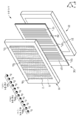
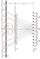
도 1은 제1 실시예에 따른 표시 장치가 가상적으로 분리될 때의 개략적인 사시도이다.
도 2a 및 도 2b는 각각, 백 배리어 타입 표시 장치에서 무아레(moire) 변조도의 시뮬레이션 결과를 예시하는 그래프 및 프런트 배리어 타입 표시 장치에서 무아레 변조도의 시뮬레이션 결과를 예시하는 그래프이다.
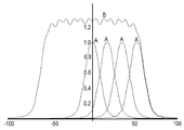
도 3a 및 도 3b는 각각, 부분 코히어런스 이론의 휘도 계산에 기초한 계산을 통해 획득된 휘도 프로파일의 일례를 예시하는 그래프, 및 투과형 표시 패널의 화소의 형상 및 시차 배리어에서의 광 투과부의 형상을 포함하는 회절 계산을 예시하는 화소들, 광 투과부들 등의 개념도이다.
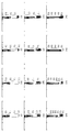
도 4의 (a) 내지 (l)은 백 배리어 타입 표시 장치에서 파라미터로서 W1/ND를 사용함으로써 부분 코히어런스 이론의 조명 계산에 기초한 계산을 통해 획득된 휘도 프로파일을 나타내는 그래프이다.
도 5의 (a) 내지 (g)는 프런트 배리어 타입 표시 장치에서 파라미터로서 W1/ND를 사용함으로써 부분 코히어런스 이론의 조명 계산에 기초한 계산을 통해 획득된 휘도 프로파일을 나타내는 그래프이다.
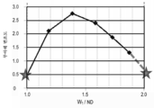
도 6a 및 도 6b는 각각, 백 배리어 타입 표시 장치에서 무아레 변조도를 실제로 측정한 결과를 예시하는 그래프 및 프런트 배리어 타입 표시 장치에서 무아레 변조도를 실제로 측정한 결과를 예시하는 그래프이다.
도 7a 및 도 7b는 백 배리어 타입 표시 장치에서 W1=α·ND 및 W1=2α·ND일 때 크로스토크가 어떻게 변하는지를 실제로 측정한 결과들을 예시하는 그래프들이다.
도 8은 제1 실시예에 따른 백 배리어 타입 표시 장치에서 시차 배리어를 형성하는 액정 표시 디바이스의 개략적 부분 단면도이다.
도 9a 및 도 9b는 제1 실시예에 따른 표시 장치에서 시차 배리어를 형성하는 액정 표시 디바이스의 W1/ND=1.0 및 W1/ND=2.0에서의 동작 상태를 예시하는 액정 표시 디바이스의 개략적 부분 단면도들이다.
도 10은 제2 실시예에 따른 표시 장치에서 시차 배리어를 형성하는 액정 표시 디바이스의 개략적 부분 단면도이다.
도 11a 및 도 11b는 제2 실시예에 따른 표시 장치에서 시차 배리어를 형성하는 액정 표시 디바이스의 W1/ND=1.0 및 W1/ND=2.0에서의 동작 상태를 예시하는 액정 표시 디바이스의 개략적 부분 단면도들이다.
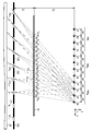
도 12는 제3 실시예에 따른 표시 장치가 가상으로 분리될 때의 개략적인 사시도이다.
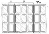
도 13은 제3 실시예에 따른 표시 장치에서의 투과형 표시 패널과 시차 배리어 사이의 배치 관계를 예시하는 개략도이다.
도 14는 제3 실시예의 변형예에 따른 표시 장치가 가상으로 분리될 때의 개략적인 사시도이다.
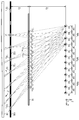
도 15는 제4 실시예에 따른 표시 장치가 가상으로 분리될 때의 개략적인 사시도이다.
도 16은 제4 실시예에 따른 백 배리어 타입 표시 장치에서 시차 배리어를 형성하는 액정 표시 디바이스의 개략적 부분 단면도이다.
도 17a 및 도 17b는 제4 실시예에 따른 표시 장치에서 시차 배리어를 형성하는 액정 표시 디바이스의 W1/ND=α 및 W1/ND=(α+1)에서의 동작 상태들을 예시하는 액정 표시 디바이스의 개략적 부분 단면도들이다.
도 18은 제5 실시예에 따른 표시 장치에서 시차 배리어를 형성하는 액정 표시 디바이스의 개략적 부분 단면도이다.
도 19a 및 도 19b는 제5 실시예에 따른 표시 장치에서 시차 배리어를 형성하는 액정 표시 디바이스의 W1/ND=α 및 W1/ND=(α+1)에서의 동작 상태들을 예시하는 액정 표시 디바이스의 개략적 부분 단면도들이다.
도 20은 제1 실시예에 따른 표시 장치에서 투과형 표시 패널, 시차 배리어, 및 면 조명 디바이스 사이의 배치 관계를 예시하는 표시 장치의 개략적 부분 단면도이다.
도 21은 도 1에 예시된 관찰 영역들에서의 시점들(D1, D2, D3 및 D4), 투과형 표시 패널, 시차 배리어, 및 면 조명 디바이스 사이의 배치 관계를 예시하는 개략도이다.
도 22는 화소들로부터의 광 빔들이 중앙 관찰 영역의 시점들(D1, D2, D3 및 D4)을 향해 이동하도록 충족된 조건을 예시하는 개략도이다.
도 23은 화소들로부터의 광 빔들이 좌측 관찰 영역의 시점들(D1, D2, D3 및 D4)을 향해 이동하도록 충족된 조건을 예시하는 개략도이다.
도 24는 중앙 관찰 영역의 시점들(D1, D2, D3 및 D4)에서 관찰된 화상을 예시하는 개략도이다.
도 25는 좌측 관찰 영역의 시점들(D1, D2, D3 및 D4)에서 관찰된 화상을 예시하는 개략도이다.
도 26은 우측 관찰 영역의 시점들(D1, D2, D3 및 D4)에서 관찰된 화상을 예시하는 개략도이다.
도 27은 제4 실시예에 따른 표시 장치에서 투과형 표시 패널, 시차 배리어, 및 면 조명 디바이스 사이의 배치 관계를 예시하는 표시 장치의 개략적 부분 단면도이다.
도 28a 및 도 28b는 형상에 기인한 무아레가 발생하지 않는다는 것을 예시하는, 투과형 표시 패널과 시차 배리어 사이의 배치 관계를 예시하는 개락도들이다.
도 29a 및 도 29b는 형상에 기인한 무아레가 발생하는 원인을 예시하는, 투과형 표시 패널과 시차 배리어 사이의 배치 관계를 예시하는 개락도들이다.
도 30은 종래 기술에서의 표시 장치에 무아레가 발생하는 상태를 예시하는 사진이다.1 is a schematic perspective view of a display device according to the first embodiment when it is virtually separated.
2A and 2B are graphs illustrating simulation results of moire modulation degree in the back barrier type display device and graphs illustrating simulation results of moire modulation degree in the front barrier type display device, respectively.
3A and 3B are graphs illustrating an example of a luminance profile obtained through calculation based on luminance calculation of the partial coherence theory, and the shape of the pixel of the transmissive display panel and the shape of the light transmitting portion in the parallax barrier, respectively. It is a conceptual diagram of the pixels, the light transmission parts, etc. which illustrate the diffraction calculation to include.
4 (a) to (l) are graphs showing luminance profiles obtained through calculations based on illumination calculations of partial coherence theory by using W 1 / ND as a parameter in a back barrier type display device.
5A to 5G are graphs showing luminance profiles obtained through calculations based on illumination calculations of partial coherence theory by using W 1 / ND as a parameter in a front barrier type display device.
6A and 6B are graphs illustrating a result of actually measuring the moire modulation degree in the back barrier type display device and a graph illustrating the result of actually measuring the moire modulation degree in the front barrier type display device, respectively.
7A and 7B are graphs illustrating results of actually measuring how crosstalk changes when W 1 = α · ND and W 1 = 2α · ND in a back barrier type display device.
8 is a schematic partial cross-sectional view of a liquid crystal display device forming a parallax barrier in the back barrier type display device according to the first embodiment.
9A and 9B are schematic portions of the liquid crystal display device illustrating the operating states at W 1 /ND=1.0 and W 1 /ND=2.0 of the liquid crystal display device forming the parallax barrier in the display device according to the first embodiment; Cross-sectional views.
10 is a schematic partial cross-sectional view of a liquid crystal display device forming a parallax barrier in the display device according to the second embodiment.
11A and 11B are schematic portions of the liquid crystal display device illustrating the operating states at W 1 /ND=1.0 and W 1 /ND=2.0 of the liquid crystal display device forming the parallax barrier in the display device according to the second embodiment; Cross-sectional views.
12 is a schematic perspective view of the display device according to the third embodiment when it is virtually separated.
13 is a schematic diagram illustrating an arrangement relationship between a transmissive display panel and a parallax barrier in the display device according to the third embodiment.
14 is a schematic perspective view of the display device according to the modified example of the third embodiment when it is virtually separated.
15 is a schematic perspective view of the display device according to the fourth embodiment when it is virtually separated.
16 is a schematic partial cross-sectional view of a liquid crystal display device forming a parallax barrier in the back barrier type display device according to the fourth embodiment.
17A and 17B are liquid crystal displays illustrating operating states at W 1 / ND = α and W 1 / ND = (α + 1) of a liquid crystal display device forming a parallax barrier in the display device according to the fourth embodiment. Schematic partial cross-sectional views of the device.
18 is a schematic partial cross-sectional view of a liquid crystal display device forming a parallax barrier in the display device according to the fifth embodiment.
19A and 19B are liquid crystal displays illustrating operating states at W 1 / ND = α and W 1 / ND = (α + 1) of a liquid crystal display device forming a parallax barrier in the display device according to the fifth embodiment; Schematic partial cross-sectional views of the device.
20 is a schematic partial cross-sectional view of a display device illustrating an arrangement relationship between a transmissive display panel, a parallax barrier, and a surface illumination device in the display device according to the first embodiment.
FIG. 21 is a schematic diagram illustrating an arrangement relationship between viewpoints D1, D2, D3 and D4, a transmissive display panel, a parallax barrier, and a surface illumination device in the viewing areas illustrated in FIG. 1.
FIG. 22 is a schematic diagram illustrating a condition met so that light beams from the pixels move toward viewpoints D1, D2, D3 and D4 of the central viewing area.
FIG. 23 is a schematic diagram illustrating a condition met so that light beams from pixels move toward viewpoints D1, D2, D3 and D4 of the left viewing area.
24 is a schematic diagram illustrating an image observed at viewpoints D1, D2, D3, and D4 of the central viewing area.
25 is a schematic diagram illustrating an image observed at viewpoints D1, D2, D3 and D4 of the left viewing area.
FIG. 26 is a schematic diagram illustrating an image observed at viewpoints D1, D2, D3 and D4 of the right viewing area.
27 is a schematic partial cross-sectional view of a display device illustrating an arrangement relationship between a transmissive display panel, a parallax barrier, and a surface illumination device in the display device according to the fourth embodiment.
28A and 28B are schematic views illustrating an arrangement relationship between a transmissive display panel and a parallax barrier, illustrating that moire due to shape does not occur.
29A and 29B are schematic views illustrating an arrangement relationship between a transmissive display panel and a parallax barrier, illustrating a cause of occurrence of moire due to shape.
30 is a photograph illustrating a state in which moire occurs in a display device according to the related art.
이하, 도면들을 참조하여 실시예들에 기초하여 본 발명이 설명될 것이지만, 본 발명은 이 실시예들에 제한되지 않고, 실시예들에서의 다양한 수치들 또는 재료들은 예들이다. 또한, 설명은 아래의 순서로 이루어질 것이다.DESCRIPTION OF EMBODIMENTS The present invention will now be described based on embodiments with reference to the drawings, but the invention is not limited to these embodiments, and various values or materials in the embodiments are examples. In addition, the description will be made in the following order.
1. 본 발명의 실시예들에 따른 전체 표시 장치의 설명1. Description of an Entire Display Device According to Embodiments of the Present Invention
2. 제1 실시예(본 발명의 실시예에 따른 표시 장치: 백 배리어 타입)2. First Embodiment (Display Device According to Embodiment of the Present Invention: Back Barrier Type)
3. 제2 실시예(제1 실시예의 변형)3. Second embodiment (variation of the first embodiment)
4. 제3 실시예(제1 실시예의 다른 변형)4. Third embodiment (another modification of the first embodiment)
5. 제4 실시예(본 발명의 실시예에 따른 표시 장치: 프런트 배리어 타입)5. Fourth Embodiment (Display Device According to Embodiment of the Present Invention: Front Barrier Type)
6. 제5 실시예(제4 실시예의 변형) 및 그 외6. Fifth embodiment (variation of the fourth embodiment) and others
1. 본 발명의 실시예들에 따른 전체 표시 장치의 설명1. Description of an Entire Display Device According to Embodiments of the Present Invention
본 발명의 일 실시예에 따른 표시 장치에서, 시차 배리어는 적어도, 제1 기판; 제1 기판 상에 형성되고 패터닝된 제1 전극; 제1 기판과 대향하도록 배치된 제2 기판; 제1 전극과 대향하도록 제2 기판 상에 형성된 제2 전극; 및 제1 기판과 제2 기판 사이에 개재된 액정층을 포함하는 액정 표시 디바이스를 가질 수도 있다. 또한, 시차 배리어가 액정 표시 디바이스를 갖는 형태는 "시차 배리어가 액정 표시 디바이스에 의해 구성되는 형태"로서 칭한다.In the display device according to the exemplary embodiment, the parallax barrier may include at least a first substrate; A first electrode formed and patterned on the first substrate; A second substrate disposed to face the first substrate; A second electrode formed on the second substrate so as to face the first electrode; And a liquid crystal layer interposed between the first substrate and the second substrate. In addition, the form in which a parallax barrier has a liquid crystal display device is called "the form in which a parallax barrier is comprised by a liquid crystal display device."
또한, 시차 배리어가 액정 표시 디바이스에 의해 구성되는 형태에서, 배면으로부터 투과형 표시 패널을 조사하는 면 조명 디바이스가 더 제공될 수도 있고, 시차 배리어는 투과형 표시 패널과 면 조명 디바이스 사이에 배치될 수도 있다. 편의상, 이 배치를 갖는 표시 장치를 "백 배리어 타입" 표시 장치로 칭한다. 또한, 이러한 경우에서, 제1 방향으로의 광 투과부의 폭이 W1이고, 제1 방향으로의 화소들의 배열 피치가 ND이며, α가 임의의 계수일 때, W1은 바람직하게는 W1=α·ND 및 W1=2α·ND의 2개의 값들로 변경되고, 또한 바람직하게는 0.95≤α≤1.05가 충족된다. 시차 배리어가 상술한 바람직한 구성을 포함하는 액정 표시 디바이스에 의해 구성되는 형태에서, 투과형 표시 패널의 헤이즈 값(haze value)은 바람직하게는 15% 이하이다. 백 배리어 타입 표시 장치에서, 시차 배리어가 표시 장치를 관찰하는 화상 관찰자에 의해 직접 관찰되지 않기 때문에, 투과형 표시 패널에 표시된 화상들의 품질은 저하되지 않고, 외부 광의 반사로 인해 시차 배리어의 표면에서 발생하는 컬러 얼룩의 문제가 없다. 또한, 투과형 표시 패널이 시차 배리어를 통해 면 조명 디바이스에 의해 조사되기 때문에, 투과형 표시 패널의 신뢰도가 면 조명 디바이스로부터의 조사광으로 인해 저하되는 문제가 거의 발생하지 않는다. 또한, 액정 표시 디바이스를 형성하는 기판들의 색 분산(chromatic dispersion)을 고려할 필요가 없다. 여기서, 헤이즈 값은 적분 구 타입(integral sphere type) 광 투과율 측정 디바이스를 사용하여 측정되는 투과형 표시 패널의 확산 투과율 및 총 광 투과율의 비율에 의존하여 평가될 수도 있다. 또한, 헤이즈 값에 관하여, 예를 들어, JIS K7136:2000를 참조한다. 투과형 표시 패널의 헤이즈 값을 상술한 값으로 설정하기 위해, 예를 들어, 이러한 헤이즈 값을 갖는 투명막이 투과형 표시 패널의 화상 관찰자와 대면하는 표면에 부착될 수도 있다. 다르게는, 예를 들어, 편광자의 표면을 조면화(roughening)하고 편광자 재료에서 상이한 굴절률들을 갖는 입상 물질들을 분산함으로써, 헤이즈 값이 제어될 수 있다. 헤이즈 값이 크면, 투과형 표시 패널로부터의 광은 관찰 영역을 향해 이동할 때 산란되어, 화상의 지향성에서의 감소가 시인되는 경우들이 있다.Further, in the form in which the parallax barrier is constituted by the liquid crystal display device, a surface illuminating device for irradiating the transmissive display panel from the back side may further be provided, and the parallax barrier may be disposed between the transmissive display panel and the surface illuminating device. For convenience, the display device having this arrangement is referred to as a "back barrier type" display device. Also in this case, when the width of the light transmitting portion in the first direction is W 1 , the arrangement pitch of the pixels in the first direction is ND, and α is an arbitrary coefficient, W 1 is preferably W1 = α. ND and W 1 = 2α. ND are changed to two values, and preferably 0.95 ≦ α ≦ 1.05 is satisfied. In the form where the parallax barrier is comprised by the liquid crystal display device containing the above-mentioned preferable structure, the haze value of a transmissive display panel becomes like this. Preferably it is 15% or less. In a back barrier type display device, since the parallax barrier is not directly observed by the image observer observing the display device, the quality of the images displayed on the transmissive display panel is not deteriorated, and it is generated on the surface of the parallax barrier due to the reflection of external light. There is no problem of color stains. In addition, since the transmissive display panel is irradiated by the surface illumination device through the parallax barrier, the problem that the reliability of the transmissive display panel is lowered due to the irradiation light from the surface illumination device rarely occurs. In addition, there is no need to consider the chromatic dispersion of the substrates forming the liquid crystal display device. Here, the haze value may be evaluated depending on the ratio of the diffuse transmittance and the total light transmittance of the transmissive display panel measured using an integral sphere type light transmittance measuring device. In addition, regarding a haze value, JIS K7136: 2000 is referred, for example. In order to set the haze value of the transmissive display panel to the above-described value, for example, a transparent film having such a haze value may be attached to the surface facing the image observer of the transmissive display panel. Alternatively, the haze value can be controlled, for example, by roughening the surface of the polarizer and dispersing particulate materials having different refractive indices in the polarizer material. If the haze value is large, the light from the transmissive display panel is scattered when moving toward the viewing area, so that there is a case where a decrease in directivity of the image is seen.
시차 배리어의 광 투과부들 및 투과형 표시 패널의 블랙 매트릭스는 각각 규칙적으로 반복되는 형상들을 갖는다. 따라서, 시차 배리어 및 투과형 표시 패널이 평행하게 배열되는 상태에서 무아레가 발생할 수도 있다. 도 30은 종래 기술에서의 표시 장치에 무아레가 발생하는 상태를 예시하는 사진이다. 무아레는 시차 배리어의 광 투과부 및 투과형 표시 패널의 블랙 매트릭스에서의 형상들에 기인한 무아레(편의상, "형상에 기인한 무아레"라 칭함) 및 광의 회절 현상에 기인한 무아레(편의상, "회절 현상에 기인한 무아레"로 칭함)로 분류될 수도 있다.The light transmitting portions of the parallax barrier and the black matrix of the transmissive display panel each have shapes that are regularly repeated. Therefore, moire may occur in a state where the parallax barrier and the transmissive display panel are arranged in parallel. 30 is a photograph illustrating a state in which moire occurs in a display device according to the related art. Moire is due to moire due to shapes in the light transmissive portion of the parallax barrier and the black matrix of the transmissive display panel (for convenience, referred to as "moire due to shape") and moire due to diffraction phenomenon of light (for convenience, "diffraction phenomenon" Moire, due to).
상술한 바와 같이, 백 배리어 타입 표시 장치에서 0.95≤α≤1.05가 충족되어서, 후술하는 바와 같이, 회절 현상에 기인한 무아레 뿐만 아니라 형상에 기인한 무아레를 억제하는 것이 가능하다.As described above, in the back barrier type display device, 0.95 ≦ α ≦ 1.05 is satisfied, and as described later, it is possible to suppress not only moire due to diffraction phenomenon but also moire due to shape.
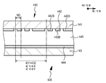
다르게는, 시차 배리어가 액정 표시 디바이스에 의해 구성되는 형태에서, 시차 배리어는 투과형 표시 패널의 전면에 배치될 수도 있다. 편의상, 이 배치를 갖는 표시 장치를 "프런트 배리어 타입" 표시 장치로 칭한다. 또한, 이러한 경우에서, 제1 방향으로의 광 투과부의 폭이 W1이고, 제1 방향으로의 화소들의 배열 피치가 ND이며, α가 1 이상의 임의의 계수일 때, W1은 바람직하게는 W1=α·ND 및 W1=(α+1)·ND의 2개의 값들로 변경되고, 또한 바람직하게는 1<α<2가 충족된다. 시차 배리어가 상술한 바람직한 구성을 포함하는 액정 표시 디바이스에 의해 구성되는 형태에서, 시차 배리어의 헤이즈 값은 바람직하게는 15% 이하이다. 시차 배리어의 헤이즈 값을 상술한 값으로 설정하기 위해, 예를 들어, 이러한 헤이즈 값을 갖는 투명막이 시차 배리어의 화상 관찰자와 대면하는 표면에 부착될 수도 있다. 다르게는, 예를 들어, 편광자의 표면을 조면화하고 편광자 재료에서 상이한 굴절률들을 갖는 입상 물질들을 분산함으로써, 헤이즈 값이 제어될 수 있다.Alternatively, in the form where the parallax barrier is constituted by the liquid crystal display device, the parallax barrier may be disposed in front of the transmissive display panel. For convenience, the display device having this arrangement is referred to as a "front barrier type" display device. Also in this case, when the width of the light transmitting portion in the first direction is W 1 , the arrangement pitch of the pixels in the first direction is ND, and α is any coefficient of 1 or more, W 1 is preferably W It is changed to two values of 1 = α · ND and W 1 = (α + 1) .ND, and also preferably 1 <α <2 is satisfied. In the form in which a parallax barrier is comprised by the liquid crystal display device containing the above-mentioned preferable structure, the haze value of a parallax barrier becomes like this. Preferably it is 15% or less. In order to set the haze value of the parallax barrier to the above-described value, for example, a transparent film having such a haze value may be attached to the surface facing the image observer of the parallax barrier. Alternatively, the haze value can be controlled, for example, by roughening the surface of the polarizer and dispersing particulate materials having different refractive indices in the polarizer material.
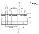
시차 배리어가 상술한 다양한 구성들을 포함하는 액정 표시 디바이스에 의해 구성되는 형태에서, 차광부를 형성하는 제1 전극의 제1 방향으로의 폭(WD21)은 제1 방향으로의 차광부의 폭(W2)보다 작다. 구체적으로는, 예를 들어, 1㎛≤W2-WD21≤15㎛가 예시될 수도 있다. 또한, 광 투과부를 형성하는 제1 전극의 제1 방향으로의 폭(WD11)은 제1 방향으로의 광 투과부의 폭(W1)보다 작다. 구체적으로는, 예를 들어, 1㎛≤W1-WD11≤15㎛가 예시될 수도 있다. 또한, 시차 배리어가 바람직한 구성을 포함하는 액정 표시 디바이스에 의해 구성되는 형태에서, 제1 방향으로의 광 투과부의 폭(W1)은 제1 전극 및 제2 전극에 대한 전압의 인가 상태에 의존하여 변한다. 이러한 경우에서, 시차 배리어를 형성하는 액정 표시 디바이스의 액정층은 전압이 제1 전극 및 제2 전극에 인가되지 않을 때 광을 투과하는 상태(노멀리 화이트(normally white)) 또는 광을 투과하지 않는 상태(노멀리 블랙(normally black))에 있을 수도 있다.In the form where the parallax barrier is constituted by the liquid crystal display device including the above-described various configurations, the width WD 21 in the first direction of the first electrode forming the light blocking portion is the width W of the light blocking portion in the first direction. Less than 2 ) Specifically, for example, 1 μm ≦ W 2 -WD 21 ≦ 15 μm may be exemplified. Further, the width WD 11 in the first direction of the first electrode forming the light transmitting part is smaller than the width W 1 of the light transmitting part in the first direction. Specifically, for example, 1 μm ≦ W 1 -WD 11 ≦ 15 μm may be exemplified. Further, in the form in which the parallax barrier is constituted by a liquid crystal display device having a preferred configuration, the width W 1 of the light transmitting portion in the first direction depends on the application state of the voltage to the first electrode and the second electrode. Change. In this case, the liquid crystal layer of the liquid crystal display device forming the parallax barrier is in a state of transmitting light (normally white) or not transmitting light when a voltage is not applied to the first electrode and the second electrode. May be in a state (normally black).
다르게는, 시차 배리어가 상술한 다양한 바람직한 구성들을 포함하는 액정 표시 디바이스에 의해 구성되는 형태에서, 제1 전극은 차광부를 형성하는 액정 표시 디바이스의 영역에 형성될 수도 있고, 광 투과부는, 제1 방향으로 평행하게 배열되는, 제1 전극이 형성되는 영역 및 제1 전극이 형성되지 않는 영역을 포함할 수도 있고, 광 투과부를 형성하는 제1 전극의 제1 방향으로의 폭(WD11)은 제1 방향으로의 광 투과부의 폭(W1)보다 작다. 구체적으로는, 예를 들어, 1㎛≤W1-WD11≤15㎛가 예시될 수도 있다. 또한, 이러한 경우에서, 시차 배리어를 형성하는 액정 표시 디바이스의 액정층은 전압이 제1 전극 및 제2 전극에 인가되지 않을 때 광을 투과하는 상태(노멀리 화이트)에 있어야 한다. 또한, 시차 배리어가 바람직한 구성을 포함하는 액정 표시 디바이스에 의해 구성되는 형태에서, 제1 방향으로의 광 투과부의 폭은 제1 전극 및 제2 전극에 대한 전압의 인가 상태에 의존하여 변할 수도 있다.Alternatively, in the form in which the parallax barrier is constituted by the liquid crystal display device including the various preferred configurations described above, the first electrode may be formed in the region of the liquid crystal display device forming the light shielding portion, and the light transmitting portion is formed in the first direction. May include a region in which the first electrode is formed and a region in which the first electrode is not formed, and the width WD 11 in the first direction of the first electrode forming the light transmissive portion is arranged to be parallel to each other. It is smaller than the width W 1 of the light transmitting part in the direction. Specifically, for example, 1 μm ≦ W 1 -WD 11 ≦ 15 μm may be exemplified. Also in this case, the liquid crystal layer of the liquid crystal display device forming the parallax barrier must be in a state (normally white) that transmits light when no voltage is applied to the first electrode and the second electrode. Further, in the form where the parallax barrier is constituted by a liquid crystal display device having a preferred configuration, the width of the light transmitting portion in the first direction may vary depending on the application state of the voltage to the first electrode and the second electrode.
또한, 상술한 다양한 바람직한 구성들을 포함하는, 본 발명의 실시예에 따른 표시 장치에서, 시차 배리어의 광 투과부들 및 차광부들은 제2 방향과 평행하게 연장될 수도 있거나, 시차 배리어의 축선과 제2 방향에 의해 형성되는 각도(θ)는 예각일 수도 있다. 특히, 제2 방향으로의 화소들의 배열 피치가 ND2일 때, θ가 아래의 식을 충족하는 경우를 고려하면, θ=tan-1(ND2/ND)가 충족되어서, 화소들과 이 화소들에 대향하는 시차 배리어의 광 투과부들 사이의 위치 관계는 시차 배리어의 축선을 따라 항상 동일하다. 따라서, 입체 표시가 수행될 때 크로스토크의 발생을 억제할 수 있어서, 고화질 입체 표시를 실현할 수 있다. 다르게는, 시차 배리어를 형성하는 광 투과부들은 시차 배리어의 축선을 따라 직선 형상으로 배열될 수도 있거나, 시차 배리어를 형성하는 광 투과부들은 시차 배리어의 축선을 따라 계단 패턴으로 배열될 수도 있다.Further, in the display device according to the embodiment of the present invention, which includes the above-described various preferable configurations, the light transmitting portions and the light blocking portions of the parallax barrier may extend in parallel with the second direction, or the axis and the second axis of the parallax barrier. The angle θ formed by the direction may be an acute angle. In particular, considering the case where θ satisfies the following equation when the arrangement pitch of the pixels in the second direction is ND 2 , θ = tan −1 (ND 2 / ND) is satisfied so that the pixels and the pixel The positional relationship between the light transmissive portions of the parallax barrier opposite the field is always the same along the axis of the parallax barrier. Therefore, generation of crosstalk can be suppressed when stereoscopic display is performed, and high quality stereoscopic display can be realized. Alternatively, the light transmitting portions forming the parallax barrier may be arranged in a straight line along the axis of the parallax barrier, or the light transmitting portions forming the parallax barrier may be arranged in a staircase pattern along the axis of the parallax barrier.
상술한 다양한 바람직한 형태들 및 구성들을 포함하는, 본 발명의 실시예에 따른 표시 장치(이하, 몇몇 경우들에서 "본 발명의 실시예에 따른 표시 장치"로 총칭함)에서, 투과형 표시 패널은 예를 들어, 액정 표시 패널을 포함할 수도 있다. 액정 표시 패널의 구성, 구조 또는 구동 방법은 특별하게 제한되지 않는다. 투과형 표시 패널은 단색(monochrome) 표시 또는 컬러 표시를 수행할 수도 있다. 또한, 패시브 매트릭스 타입 또는 액티브 매트릭스 타입이 이용될 수도 있다. 후술하는 각 실시예에서, 액티브 매트릭스 타입 액정 표시 패널이 투과형 표시 패널로서 사용된다. 액정 표시 패널은 예를 들어, 투명 제1 전극을 갖는 프런트 패널, 투명 제2 전극을 갖는 리어 패널(rear panel), 및 프런트 패널과 리어 패널 사이에 배치된 액정 재료를 포함한다. 또한, 각 화소가 반사 영역 및 투과 영역을 갖는 소위 반투과형 액정 표시 패널이 본 발명의 실시예에 따른 표시 장치 등의 투과형 표시 패널에 또한 포함된다.In the display device according to the embodiment of the present invention (hereinafter, collectively referred to as "display device according to the embodiment of the present invention" in some cases) including the various preferred forms and configurations described above, the transmissive display panel is an example. For example, a liquid crystal display panel may be included. The configuration, structure or driving method of the liquid crystal display panel is not particularly limited. The transmissive display panel may perform monochrome display or color display. In addition, a passive matrix type or an active matrix type may be used. In each embodiment described later, an active matrix type liquid crystal display panel is used as the transmissive display panel. The liquid crystal display panel includes, for example, a front panel having a transparent first electrode, a rear panel having a transparent second electrode, and a liquid crystal material disposed between the front panel and the rear panel. In addition, a so-called transflective liquid crystal display panel in which each pixel has a reflective region and a transmissive region is also included in a transmissive display panel such as a display device according to an embodiment of the present invention.
여기서, 더욱 구체적으로, 프런트 패널은 예를 들어, 유리 기판으로 구성된 제1 기판, 제1 기판의 내면에 제공된 투명 제1 전극(또한 공통 전극이라 칭하고, 예를 들어, 인듐 주석 산화물(ITO)로 이루어짐), 및 제1 기판의 외면에 제공된 편광 필름을 포함한다. 또한, 컬러 액정 표시 패널에서, 프런트 패널은 아크릴계 수지 또는 에폭시계 수지로 이루어진 오버코트 층으로 코팅된 컬러 필터가 제1 기판의 내면에 제공되고, 투명 제1 전극은 오버코트 층 상에 형성되는 구성을 갖는다. 배향층이 투명 제1 전극 상에 형성된다. 컬러 필터의 배치 패턴은 델타 배열, 스트라이프 배열, 대각 배열, 및 직사각형 배열을 포함할 수도 있다.Here, more specifically, the front panel is, for example, a first substrate composed of a glass substrate, a transparent first electrode provided on the inner surface of the first substrate (also called a common electrode, for example, indium tin oxide (ITO)). Made up), and a polarizing film provided on an outer surface of the first substrate. Further, in the color liquid crystal display panel, the front panel has a configuration in which a color filter coated with an overcoat layer made of acrylic resin or epoxy resin is provided on the inner surface of the first substrate, and the transparent first electrode is formed on the overcoat layer. . An alignment layer is formed on the transparent first electrode. The arrangement pattern of the color filters may include delta arrangement, stripe arrangement, diagonal arrangement, and rectangular arrangement.
한편, 더욱 구체적으로, 리어 패널은 예를 들어, 유리 기판으로 구성된 제2 기판, 제2 기판의 내면에 형성된 스위칭 소자, 그 스위칭 소자에 의해 도통 및 비도통이 제어되는 투명 제2 전극(또한 화소 전극이라 칭하고, 예를 들어, ITO로 이루어짐), 및 제2 기판의 외면에 제공된 편광 필름을 포함한다. 배향층이 투명 제2 전극상을 포함하는 전체면상에 형성된다. 투과형 액정 표시 패널을 형성하는 다양한 부재들 또는 액정 재료들은 널리 알려진 부재들 또는 재료들을 포함할 수도 있다. 또한, 스위칭 소자로서, 박막 트랜지스터(TFT)와 같은 3 단자 소자, MIM (Metal Insulator Metal) 소자, 배리스터 소자, 또는 다이오드와 같은 2 단자 소자가 예시될 수도 있다.On the other hand, more specifically, the rear panel includes, for example, a second substrate composed of a glass substrate, a switching element formed on the inner surface of the second substrate, and a transparent second electrode (conducting pixel) in which conduction and non-conduction are controlled by the switching element. Called an electrode, consisting of, for example, ITO), and a polarizing film provided on an outer surface of the second substrate. An alignment layer is formed on the entire surface including the transparent second electrode phase. Various members or liquid crystal materials forming the transmissive liquid crystal display panel may include well known members or materials. Further, as the switching element, a three terminal element such as a thin film transistor (TFT), a metal insulator metal (MIM) element, a varistor element, or a two terminal element such as a diode may be exemplified.
또한, 컬러 액정 표시 패널에서, 투명 제1 전극 및 투명 제2 전극의 중첩 영역이고 액정 셀을 포함하는 영역이 부화소에 대응한다. 또한, 각 화소를 형성하는 적색 발광 부화소는 관련 영역과 적색을 투과하는 컬러 필터의 조합을 포함하고, 녹색 발광 부화소는 관련 영역과 녹색을 투과하는 컬러 필터의 조합을 포함하며, 청색 발광 부화소는 관련 영역과 청색을 투과하는 컬러 필터의 조합을 포함한다. 적색 발광 부화소, 녹색 발광 부화소, 및 청색 발광 부화소의 배치 패턴은 상술한 컬러 필터들의 패치 패턴과 일치한다. 또한, 각 화소는 하나의 종류 또는 복수의 종류의 부화소들을 3개의 종류의 부화소들에 더함으로써 획득된 부화소들의 세트를 포함할 수도 있다(예를 들어, 휘도를 증가시키기 위해 백색광을 발광하는 부화소를 더함으로써 획득된 부화소들의 세트, 컬러 영역을 확대하기 위해 보색을 발광하는 부화소를 더함으로써 획득된 부화소들의 세트, 컬러 영역을 확대하기 위해 옐로우를 발광하는 부화소를 더함으로써 획득된 부화소들의 세트, 및 컬러 영역을 확대하기 위해 옐로우 및 시안을 발광하는 부화소들을 더함으로써 획득된 부화소들의 세트). 또한, 이러한 구성에서, 각 부화소는 본 발명의 실시예에 따른 표시 장치 등의 투과형 표시 패널에서의 "화소"에 대응한다.Also, in the color liquid crystal display panel, a region overlapping the transparent first electrode and the transparent second electrode and including the liquid crystal cell corresponds to the subpixel. In addition, the red light emitting subpixel forming each pixel includes a combination of a related area and a color filter transmitting red color, and the green light emitting subpixel includes a combination of a color filter transmitting a related area and green color, and a blue light emitting part The pixel comprises a combination of color filters that transmit the relevant area and blue. The arrangement pattern of the red light emitting subpixel, the green light emitting subpixel, and the blue light emitting subpixel matches the patch pattern of the color filters described above. Each pixel may also include a set of subpixels obtained by adding one or a plurality of subpixels to three subpixels (eg, emitting white light to increase luminance). A set of subpixels obtained by adding a subpixel, a set of subpixels obtained by adding a subpixel that emits complementary colors to enlarge the color gamut, and a subpixel that emits yellow to enlarge the color gamut Set of subpixels, and a set of subpixels obtained by adding subpixels emitting yellow and cyan to enlarge the color gamut). Also, in such a configuration, each subpixel corresponds to a "pixel" in a transmissive display panel such as a display device according to an embodiment of the present invention.
프런트 배리어 타입 표시 장치에서, 투과형 표시 패널은 예를 들어, 전계 발광 표시 패널 또는 플라즈마 표시 패널을 더 포함할 수도 있다.In the front barrier type display device, the transmissive display panel may further include, for example, an electroluminescent display panel or a plasma display panel.
2차원 매트릭스로 배열된 화소들의 수(M×N)를 (M, N)으로 표기할 때, (M, N)의 값들로서, 구체적으로는, VGA (640,480), S-VGA(800,600), XGA (1024,768), APRC (1152,900), S-XGA(1280,1024), U-XGA (1600,1200), HD-TV (1920,1080), 및 Q-XGA(2048,1536) 이외에, (1920,1035), (720,480), 및 (1280,960)과 같은 화상 표시 해상도들 중 몇몇이 예시될 수도 있고, 이들의 수는 이들 값으로 제한되지 않는다.When the number M × N of the pixels arranged in the two-dimensional matrix is expressed as (M, N), the values of (M, N) are specifically, VGA (640,480), S-VGA (800,600), XGA (1024,768), APRC (1152,900), S-XGA (1280,1024), U-XGA (1600,1200), HD-TV (1920,1080), and Q-XGA (2048,1536) In addition, some of the image display resolutions such as (1920, 1035), (720, 480), and (1280, 960) may be illustrated, and their number is not limited to these values.
시차 배리어를 형성하는 액정 표시 디바이스의 구성 및 구조는, 화소들 및 부화소들의 구성 및 구조를 제외하고 투과형 표시 패널을 형성하는 액정 표시 패널의 구성 및 구조와 동일하거나 유사하다. 여기서, 시차 배리어를 형성하는 액정 표시 디바이스가 바람직하게는 소위 광 셔터로서 기능하기 때문에, 화상들을 표시하는 통상의 액정 표시 디바이스에서 필요한 스위치 소자 또는 컬러 필터는 불필요하고, 구성 및 구조를 간소화할 수 있으며, 높은 신뢰성 및 긴 수명을 확보할 수 있다. 또한, 블랙 매트릭스가 형성될 필요가 없기 때문에, 전체 액정 표시 디바이스에 대한 제조 프로세스를 간소화할 수 있다. 투과형 표시 패널 및 액정 표시 디바이스의 제1 기판은 서로 대향할 수도 있거나, 투과형 표시 패널 및 액정 표시 디바이스의 제2 기판은 서로 대향할 수도 있다.The structure and structure of the liquid crystal display device forming the parallax barrier are the same as or similar to the structure and structure of the liquid crystal display panel forming the transmissive display panel except for the structure and structure of the pixels and subpixels. Here, since the liquid crystal display device forming the parallax barrier preferably functions as a so-called light shutter, the switch element or color filter necessary in the conventional liquid crystal display device for displaying images is unnecessary, and the configuration and structure can be simplified. High reliability and long life can be ensured. In addition, since the black matrix does not need to be formed, the manufacturing process for the entire liquid crystal display device can be simplified. The first substrate of the transmissive display panel and the liquid crystal display device may be opposite to each other, or the second substrate of the transmissive display panel and the liquid crystal display device may be opposed to each other.
본 발명의 실시예에 따른 표시 장치 등에서의 면 조명 디바이스(백라이트)는 널리 알려진 면 조명 디바이스를 포함할 수도 있다. 즉, 면 조명 디바이스는 직하형 면 광원 디바이스, 또는 에지 라이트형(사이드 라이트형이라 또한 칭함) 면 광원 디바이스일 수도 있다. 여기서, 직하형 면 광원 디바이스는 예를 들어, 케이싱에 제공된 광원, 광원 아래에 위치된 케이싱부에 배치되어 광원으로부터의 출사광을 상향으로 반사하는 반사 부재, 및 광원의 위에 위치된 케이싱 개구에 장착되고 광원으로부터의 출사광 및 반사 부재로부터의 반사광을 확산시키면서 통과시키는 확산판을 포함한다. 한편, 에지 라이트형 면 광원 디바이스는 예를 들어, 도광판 및 그 도광판의 측면에 배치된 광원을 포함한다. 또한, 반사 부재가 도광판 아래에 배치되고, 확산 시트 및 프리즘 시트가 도광판 위에 배치된다. 광원은 예를 들어, 냉음극 형광 램프를 포함하고, 백색광을 발광한다. 다르게는, 광원은 예를 들어, LED 또는 반도체 레이저 디바이스와 같은 발광 디바이스를 포함한다.The surface lighting device (backlight) in the display device or the like according to the embodiment of the present invention may include a well-known surface lighting device. That is, the surface illuminating device may be a direct type surface light source device or an edge light type (also called side light type) surface light source device. Here, the direct type surface light source device is mounted to, for example, a light source provided in the casing, a reflecting member disposed in the casing portion positioned below the light source and reflecting upwardly the emitted light from the light source, and a casing opening located above the light source. And a diffuser plate configured to pass through the light emitted from the light source and the reflected light from the reflective member. On the other hand, the edge light type surface light source device includes, for example, a light guide plate and a light source disposed on the side of the light guide plate. In addition, a reflective member is disposed below the light guide plate, and a diffusion sheet and a prism sheet are disposed above the light guide plate. The light source includes, for example, a cold cathode fluorescent lamp and emits white light. Alternatively, the light source includes a light emitting device such as, for example, an LED or semiconductor laser device.
면 조명 디바이스 또는 투과형 표시 패널을 구동하는 구동기는 예를 들어, 화상 신호 처리 유닛, 타이밍 제어 유닛, 데이터 구동기, 게이트 구동기, 및 광원 제어 유닛과 같은 다양한 회로들을 포함할 수도 있다. 이들은 널리 알려진 회로 소자들을 포함할 수도 있다.The driver for driving the surface illumination device or the transmissive display panel may include various circuits such as, for example, an image signal processing unit, a timing control unit, a data driver, a gate driver, and a light source control unit. These may include well known circuit elements.
본 발명의 실시예에 따른 표시 장치에서, 입체 화상들 및 2차원 화상들이 표시될 수 있거나, 상이한 각도들로부터 표시 장치를 볼 때 상이한 화상들이 표시될 수 있다. 또한, 이러한 경우에서, 표시 장치에 전송된 화상 데이터는 입체 화상들을 표시하는 데 필요한 화상 데이터, 또는 2차원 화상들을 표시하는 데 필요한 화상 데이터일 수도 있다.In the display device according to the embodiment of the present invention, stereoscopic images and two-dimensional images may be displayed, or different images may be displayed when viewing the display device from different angles. Further, in this case, the image data transmitted to the display device may be image data necessary for displaying stereoscopic images, or image data necessary for displaying two-dimensional images.
광 투과부의 폭(W1)의 변경은 예를 들어, 표시 장치에 체인지오버 스위치(changeover switch)를 제공하여 화상 관찰자가 체인지오버 스위치를 조작함으로써 수행될 수도 있거나, 광 투과부의 폭(W1)의 변경은 표시될 화상 데이터를 분석하는 표시 장치의 화상 신호 처리 유닛에 의해 자동으로 수행될 수도 있다. 화질을 중요시하고 화상의 휘도를 중요시하지 않는 경우에서, 광 투과부의 폭(W1)은 작게 이루어지고([W1=α·ND]), 휘도를 중요시하고 화질을 중요시하지 않는 경우에서, 광 투과부의 폭(W1)은 크게 이루어진다([W1=2α·ND 또는 W1=(α+1)·ND]). 여기서, 광 투과부의 폭(W1)이 큰 경우에, 큰 입체감을 갖는 입체 화상들이 투과형 표시 패널에 표시될 때, 약간이지만, 입체 화상들이 이중화될 수도 있거나 입체 화상들에 일부 블러링(blurring)이 발생할 수도 있다. 따라서, 화상 신호 처리 유닛이 표시될 화상 데이터의 깊이 맵(depth map)을 분석하고 큰 입체감을 갖는 입체 화상들이 그 분석 결과에 기초하여 투과형 표시 패널에 표시된다는 것을 결정하는 경우에, 화상 신호 처리 유닛은 광 투과부의 폭(W1)을 감소시키도록 변경을 수행할 수도 있고, 반대로, 화상 신호 처리 유닛이 작은 입체감을 갖는 입체 화상들이 투과형 표시 패널에 표시된다는 것을 결정하는 경우에, 화상 신호 처리 유닛은 광 투과부의 폭(W1)을 증가시키도록 변경을 수행할 수도 있다. 또한, 이러한 경우에서, 광 투과부의 폭(W1)에서의 빈번한 변경으로 인해 크게 변하는 투과형 표시 패널의 휘도의 문제가 있지만, 면 조명 디바이스로부터 출사되는 광의 양을 적절하게 제어함으로써(면 조명 디바이스의 광원의 동작 제어) 투과형 표시 패널의 휘도가 크게 변하는 것을 억제할 수 있다.Changing the width (W 1) of the light transmission, for example, provide a change-over switches (changeover switch) in the display device to the image viewer that the width of the light transmission or may be performed by operating the change-over switch (W 1) The change of may be performed automatically by the image signal processing unit of the display device for analyzing the image data to be displayed. In the case where the image quality is important and the luminance of the image is not important, the width W 1 of the light transmitting portion is made small ([W 1 = α · ND]), and in the case where the luminance is important and the image quality is not important, The width W 1 of the transmission portion is made large ([W 1 = 2α · ND or W 1 = (α + 1) .ND]). Here, when the width W 1 of the light transmitting portion is large, when three-dimensional images having a large three-dimensional feeling are displayed on the transmissive display panel, the three-dimensional images may be doubled or some blurring on the three-dimensional images. This may occur. Therefore, when the image signal processing unit analyzes a depth map of image data to be displayed and determines that stereoscopic images having a large three-dimensional effect are displayed on the transmissive display panel based on the analysis result, the image signal processing unit May perform a change to reduce the width W 1 of the light transmitting portion, and conversely, when the image signal processing unit determines that stereoscopic images having a small three-dimensional feeling are displayed on the transmissive display panel, the image signal processing unit May perform the change to increase the width W 1 of the light transmitting portion. Further, in such a case, there is a problem of the luminance of the transmissive display panel which varies greatly due to frequent changes in the width W 1 of the light transmitting portion, but by appropriately controlling the amount of light emitted from the surface illuminating device (of the surface illuminating device) Operation Control of Light Source) It is possible to suppress large change in luminance of the transmissive display panel.
2. 제1 실시예2. First embodiment
제1 실시예는 본 발명에 따른 표시 장치에 관한 것으로, 더욱 구체적으로는, 소위 배리어 타입 표시 장치에 관한 것이다. 도 1은 제1 실시예에 따른 표시 장치가 가상적으로 분리될 때의 개략적인 사시도이고, 도 20은 제1 실시예에 따른 표시 장치에서 투과형 표시 패널(10), 시차 배리어(130), 및 면 조명 디바이스(20) 사이의 배치 관계를 예시하는 표시 장치의 일부의 개략적인 단면도이다.The first embodiment relates to a display device according to the present invention, and more particularly to a so-called barrier type display device. 1 is a schematic perspective view of a virtually separated display device according to a first embodiment, and FIG. 20 illustrates a
도 1에 예시되어 있는 바와 같이, 제1 실시예에 따른 표시 장치는 제1 방향(이 실시예에서, 구체적으로는, 수평 방향 또는 X 방향) 및 제1 방향과는 상이한 제2 방향(이 실시예에서, 구체적으로는, 수직 방향 또는 Y 방향)으로 2차원 매트릭스로 배열되는 화소들(12)을 갖는 투과형 표시 패널(10), 및 투과형 표시 패널(10) 상에 표시된 화상들을 복수의 시점용 화상들로 분리하는 시차 배리어(130)를 포함한다.As illustrated in FIG. 1, the display device according to the first embodiment includes a first direction (in this embodiment, specifically, a horizontal direction or an X direction) and a second direction different from the first direction (this embodiment). In the example, specifically, the
투과형 표시 패널(10)은 액티브 매트릭스 컬러 액정 표시 패널을 포함한다. 투과형 표시 패널(10)의 표시 영역(11)에서, M개의 화소들(12)이 제1 방향(수평 방향 또는 X 방향)으로 배열되고, N개의 화소들(12)이 제2 방향(수직 방향 또는 Y 방향)으로 배열된다. m번째(여기서, m=1, 2, …, M) 화소(12)가 화소(12m)으로 표시된다. 화소들(12) 각각은 적색 발광 부화소, 녹색 발광 부화소, 및 청색 발광 부화소를 포함한다. 투과형 표시 패널(10)은 관찰 영역측의 프런트 패널, 시차 배리어측의 리어 패널, 및 프런트 패널과 리어 패널 사이에 배치된 액정 재료를 포함한다. 또한, 도면의 간소화를 위해, 도 1, 도 12, 도 14 및 도 15에서는, 투과형 표시 패널(10)이 단일 패널로서 예시되어 있다.The
투과형 표시 패널(10)을 형성하는 액정 표시 패널은 투명 제1 전극을 갖는 프런트 패널, 투명 제2 전극을 갖는 리어 패널, 및 프런트 패널과 리어 패널 사이에 배치된 액정 재료를 포함한다. 또한, 프런트 패널은 유리 기판으로 구성된 제1 기판, 제1 기판의 내면에 제공된 투명 제1 전극, 및 제1 기판의 외면에 제공된 편광 필름을 포함한다. 또한, 아크릴계 수지 또는 에폭시계 수지로 이루어진 오버코트 층으로 코팅된 컬러 필터가 제1 기판의 내면에 제공되고, 투명 제1 전극은 오버코트 층상에 형성된다. 배향층이 투명 제1 전극 상에 형성된다. 한편, 리어 패널은 유리 기판으로 구성된 제2 기판, 제2 기판의 내면에 형성된 스위칭 소자, 그 스위칭 소자에 의해 도통 및 비도통이 제어되는 투명 제2 전극, 및 제2 기판의 외면에 제공된 편광 필름을 포함한다. 배향층이 투명 제2 전극상을 포함하는 전체면상에 형성된다. 또한, 투명 제1 전극 및 투명 제2 전극의 중첩 영역이고 액정 셀을 포함하는 영역이 부화소에 대응한다.The liquid crystal display panel forming the
또한, 제1 실시예에 따른 표시 장치는 배면으로부터 투과형 표시 패널(10)을 조사하는 면 조명 디바이스(20)를 포함한다. 또한, 시차 배리어(130)는 투과형 표시 패널(10)과 면 조명 디바이스(20) 사이에 배치된다.In addition, the display device according to the first embodiment includes a
다시 말해, 시차 배리어(130) 및 투과형 표시 패널(10)은 소정의 갭(Z1)의 공간을 갖고 서로 대향하도록 배치된다. 구체적으로는, 제1 실시예에 따른 표시 장치에서, 투과형 표시 패널(10) 및 시차 배리어(130)는 서로 이격되도록 배치된다. 공간은 공기층 또는 진공층으로 채워질 수도 있거나, 투명 부재(미도시)로 채워질 수도 있고, 광 경로 길이는 공간을 차지하는 재료의 굴절률을 고려하여 Z1이 될 수도 있다. 또한, 시차 배리어(130)는 제2 방향(수직 방향 또는 Y 방향)에 평행한 축선(AX) 또는 제2 방향(수직 방향 또는 Y 방향)과 예각을 형성하는 축선(AX)을 따라 연장되고 교대로 평행하게 배열되는 복수의 광 투과부(131) 및 복수의 차광부(132)를 포함한다. 또한, 제1 실시예에서, 광 투과부들(131) 및 차광부들(132)은 제2 방향(수직 방향 또는 Y 방향)에 평행하게 연장된다. 즉, 시차 배리어(130)의 축선(AX)은 제2 방향(수직 방향 또는 Y 방향)에 평행하다. 제1 방향으로의 광 투과부(131)의 폭(W1)은 가변이다. 광 투과부들(개구들)(131)은 제1 방향(수평 방향 또는 X 방향)에서 복수(P개)로 배치된다. p번째(여기서, p=1, 2, …, P) 광 투과부(131)가 광 투과부(131p)로 표시된다. "P"와 상술한 "M" 사이의 관계는 도 21, 도 22 및 도 23을 참조하여 후술될 것이다.In other words, the
면 조명 디바이스(20)는 예를 들어, 직하형 면 광원 디바이스를 포함한다. LED를 포함하는 광원으로부터 출사되어 확산판 등을 통과하는 확산광은 발광면(21)으로부터 출사되어 투과형 표시 패널(10)의 배면에 인가된다. 면 조명 디바이스(20)의 광의 일부가 시차 배리어(130)에 의해 차단되는 경우에, 투과형 표시 패널(10)에 의해 표시된 화상들은 복수의 시점용 화상들로 분리된다.The
또한, 시차 배리어(130)와 투과형 표시 패널(10) 사이의 거리, X 방향으로의 화소들(12)의 배열 피치(이하, 일부 경우들에서 "화소 피치"로서 단순히 칭함), 및 X 방향으로의 광 투과부들(131)의 피치(이하, "광 투과부 피치"로서 단순히 칭함)가, 표시 장치의 사양에서 규정된 관찰 영역에서 바람직한 입체 화상들을 관찰할 수 있는 조건들을 충족시키도록 설정된다. 이하, 이러한 조건들을 상세히 설명할 것이다.Further, the distance between the
제1 실시예에서, 표시 장치에 표시된 화상들의 시점들의 수가 도 1에 예시된 각각의 관찰 영역(WAL, WAC 및 WAR)에서 시점들(D1, D2, D3 및 D4)의 4개이라고 가정하여 설명이 이루어진다. 그러나, 본 발명은 이에 제한되지 않고, 관찰 영역들의 수 또는 시점들의 수는 표시 장치의 설계들에 따라 적절하게 설정될 수도 있다.In the first embodiment, the number of viewpoints of the images displayed on the display device is four of the viewpoints D1, D2, D3 and D4 in each of the observation areas WA L , WA C and WA R illustrated in FIG. 1. The explanation is made on the assumption. However, the present invention is not limited thereto, and the number of viewing areas or the number of viewpoints may be appropriately set according to designs of the display device.
도 21은 도 1에 예시된 관찰 영역들(WAL, WAC 및 WAR)에서의 시점들(D1, D2, D3 및 D4), 투과형 표시 패널(10), 시차 배리어(130), 및 면 조명 디바이스(20) 사이의 배치 관계를 예시하는 개략도이다. 도 22는 화소들(12)로부터의 광 빔들이 중앙 관찰 영역(WAC)의 시점들(D1, D2, D3 및 D4)을 향해 이동하도록 충족된 조건을 예시하는 개략도이다. 또한, 도 23은 화소들(12)로부터의 광 빔들이 좌측 관찰 영역(WAL)의 시점들(D1, D2, D3 및 D4)을 향해 이동하도록 충족된 조건을 예시하는 개략도이다.FIG. 21 illustrates viewpoints D1, D2, D3, and D4 in the viewing areas WA L , WA C, and WA R illustrated in FIG. 1, the
설명의 편의상, 광 투과부들(131)이 X 방향으로 홀수로 평행하게 배열되고, p번째 광 투과부(131p)가 광 투과부(1311)와 광 투과부(131P) 사이의 중앙에 위치한다는 것을 가정한다. 또한, m번째 화소(12m)와 m+1번째 화소(12m+1) 사이의 경계, 및 관찰 영역(WAC)에서 시점들(D2 및 D3) 사이의 중간점은 광 투과부(131p)의 중심을 통해 Z 방향으로 연장되는 가상 직선 상에 위치한다는 것을 가정한다. 화소 피치는 "ND"(단위: mm)로 표시되고, 광 투과부 피치는 "RD"(단위: mm)로 표시된다. 또한, 광 투과부들(131)과 투과형 표시 패널(10) 사이의 거리는 "Z1"(단위: mm)으로 표시되고, 투과형 표시 패널(10)과 관찰 영역들(WAL, WAC 및 WAR) 사이의 거리는 "Z2"(단위: mm)로 표시된다. 또한, 관찰 영역들(WAL, WAC 및 WAR)에서의 인접한 시점들 사이의 거리는 "DP"(단위: mm)로 표시된다.For convenience of description, the
광 투과부(131)의 폭이 W1이고 차광부(132)의 폭이 W2일 때, 광 투과부 피치(RD), 광 투과부(131)의 폭(W1), 및 차광부(132)의 폭(W2) 사이에 RD=W1+W2의 관계가 있다.When the width of the
화소들(12m-1, 12m, 12m+1 및 12m+2)을 통과하는 광 투과부(131p)로부터 각각의 광 빔들이 중앙 관찰 영역(WAC)의 시점들(D1, D2, D3 및 D4)을 향해 이동하는 조건을 고찰한다. 설명의 편의상, 광 투과부(131)의 폭(W1)이 충분하게 작다고 가정하고 광 투과부(131)의 중심을 통과하는 광의 궤도를 주목하여 설명이 이루어질 것이다. 기준으로서 Z 방향으로 광 투과부(131p)의 중심을 통해 연장되는 가상 직선을 사용함으로써, 화소(12m+2)의 중심까지의 거리는 X1으로 표시되고, 중심 관찰 영역(WAC)의 시점(D4)까지의 거리는 X2로 표시된다. 광 투과부(131p)로부터의 광이 화소(12m+2)를 통과하여 관찰 영역(WAC)의 시점(D4)을 향해 이동할 때, 아래의 식 (1)로 표시된 조건이 기하학적인 유사성 관계로부터 충족된다.The respective light beams from the
Z1/X1=(Z1+Z2)/X2 (1)Z 1 / X 1 = (Z 1 + Z 2 ) / X 2 (1)
여기서, X1=1.5×ND이고 X2=1.5×DP이기 때문에, 이들이 반영되면, 식 (1)은 아래의 식 (1')에서와 같이 표현될 수도 있다.Here, since X 1 = 1.5 × ND and X 2 = 1.5 × DP, if they are reflected, equation (1) may be expressed as in equation (1 ') below.
Z1/(1.5×ND)=(Z1+Z2)/(1.5×DP) (1')Z 1 /(1.5×ND)=(Z 1 + Z 2 ) / (1.5 × DP) (1 ')
또한, 식 (1')이 충족되면, 화소들(12m-1, 12m, 및 12m+1) 각각을 통과하는 광 투과부(131p)로부터의 광 빔들이 관찰 영역(WAC)의 시점들(D1, D2, 및 D3)을 향해 이동한다는 것이 기하학적으로 명백하다.Also, if equation (1 ') is satisfied, the light beams from the
다음으로, 화소들(12m-1, 12m, 12m+1 및 12m+2)을 통과하는 광 투과부(131p+1)로부터 각각의 광 빔들이 좌측 관찰 영역(WAL)의 시점들(D1, D2, D3 및 D4)을 향해 이동하는 조건을 고찰한다.Next, the respective light beams from the
기준으로서 Z 방향으로 광 투과부(131p+1)의 중심을 통해 연장되는 가상 직선을 사용함으로써, 화소(12m+2)의 중심까지의 거리는 X3으로 표시되고, 좌측 관찰 영역(WAL)의 시점(D4)까지의 거리는 X4로 표시된다. 광 투과부(131p+1)로부터의 광이 화소(12m+2)를 통과하여 관찰 영역(WAL)의 시점(D4)을 향해 이동하도록, 아래의 식 (2)로 표시된 조건이 기하학적인 유사성 관계로부터 충족된다.By using a virtual straight line extending through the center of the light transmitting portion 131 p + 1 in the Z direction as a reference, the distance to the center of the
Z1/X3=(Z1+Z2)/X4 (2)Z 1 / X 3 = (Z 1 + Z 2 ) / X 4 (2)
여기서, X3=RD-X1=RD-1.5×ND 및 X4=RD+2.5×DP이기 때문에, 이들이 반영되면, 식 (2)는 아래의 식 (2')에서와 같이 표현될 수도 있다.Here, since X 3 = RD-X 1 = RD-1.5 × ND and X 4 = RD + 2.5 × DP, if they are reflected, equation (2) may be expressed as in equation (2 ') below. .
Z1/(RD-1.5×ND)=(Z1+Z2)/(RD+2.5×DP) (2')Z 1 /(RD-1.5×ND)=(Z 1 + Z 2 ) / (RD + 2.5 × DP) (2 ')
또한, 식 (2')가 충족되면, 화소들(12m-1, 12m, 및 12m+1) 각각을 통과하는 광 투과부(131p+1)로부터의 광 빔들이 관찰 영역(WAL)의 시점들(D1, D2, 및 D3)을 향해 이동한다는 것이 기하학적으로 명백하다.Also, if equation (2 ') is satisfied, light beams from the
또한, 화소들(12m-1, 12m, 12m+1 및 12m+2)을 통과하는 광 투과부(131p-1)로부터 각각의 광 빔들이 우측 관찰 영역(WAR)의 시점들(D1, D2, D3 및 D4)을 향해 이동하는 조건은 도 23을 Z 방향에 관하여 반전시킨 경우와 동일하므로, 그 설명은 생략한다.Further, the respective light beams from the
거리(Z2) 및 거리(DP)의 값들은 표시 장치의 사양에 기초하여 소정의 값들로 설정된다. 또한, 화소 피치(ND)의 값은 투과형 표시 패널(10)의 구조에 의해 규정된다. 식들 (1') 및 (2')로부터, 아래의 식들 (3) 및 (4)가 거리(Z1) 및 광 투과부 피치(RD)에 관하여 획득될 수 있다.The values of the distance Z 2 and the distance DP are set to predetermined values based on the specification of the display device. In addition, the value of the pixel pitch ND is defined by the structure of the
Z1=Z2×ND/(DP-ND) (3)Z 1 = Z 2 × ND / (DP-ND) (3)
RD=4×DP×ND/(DP-ND) (4)RD = 4 × DP × ND / (DP-ND) (4)
상술한 예에서, 광 투과부 피치(RD)의 값은 화소 피치(ND)의 값의 실질적으로 4배이다. 따라서, 상술한 "M" 및 "P"는 M![]()
![]()
도 24는 중앙 관찰 영역(WAC)의 시점들(D1, D2, D3 및 D4)에서 관찰된 화상을 예시하는 개략도이다. 또한, 도 25는 좌측 관찰 영역(WAL)의 시점들(D1, D2, D3 및 D4)에서 관찰된 화상을 예시하는 개략도이다. 또한, 도 26은 우측 관찰 영역(WAR)의 시점들(D1, D2, D3 및 D4)에서 관찰된 화상을 예시하는 개략도이다.24 is a schematic diagram illustrating the image observed at the viewpoints D1, D2, D3 and D4 of the central viewing area WA C. 25 is a schematic diagram illustrating an image observed at the viewpoints D1, D2, D3, and D4 of the left viewing area WA L. In addition, FIG. 26 is a schematic diagram illustrating an image observed at viewpoints D1, D2, D3 and D4 of the right viewing area WA R.
도 24, 도 25 및 도 26에 예시되어 있는 바와 같이, 화소들(121, 125, 129, …)과 같은 화소들(12)에 의해 형성된 화상이 시점(D1)에서 관찰되고, 화소들(122, 126, 1210,…)과 같은 화소들(12)에 의해 구성된 화상이 시점(D2)에서 관찰된다. 또한, 화소들(123, 127, 1211,…)과 같은 화소들(12)에 의해 형성된 화상이 시점(D3)에서 관찰되고, 화소들(124, 128, 1212,…)과 같은 화소들(12)에 의해 구성된 화상이 시점(D4)에서 관찰된다. 따라서, 제1 시점에 대한 화상이 화소들(121, 125, 129,…)과 같은 화소들(12)을 사용하여 표시되고, 제2 시점에 대한 화상이 화소들(122, 126, 1210,…)과 같은 화소들(12)을 사용하여 표시되고, 제3 시점에 대한 화상이 화소들(123, 127, 1211,…)과 같은 화소들(12)을 사용하여 표시되며, 제4 시점에 대한 화상이 화소들(124, 128, 1212,…)과 같은 화소들(12)을 사용하여 표시된다. 이에 의해, 화상 관찰자가 화상들을 입체 화상들로서 인식할 수 있다.As illustrated in FIGS. 24, 25 and 26, an image formed by
시점들의 수가 상기 설명에서 "4개"이지만, 시점들의 수는 표시 장치의 사양에 따라 적절하게 선택될 수도 있다. 예를 들어, 시점들의 수가 "2개" 또는 시점들의 수가 "6개"인 구성이 있을 수도 있다. 이러한 경우에서, 시차 배리어(130) 등의 구성이 적절하게 변경될 수도 있다. 이것은 또한 후술하는 제2 및 제3 실시예들에 대해 동일하다.Although the number of viewpoints is "four" in the above description, the number of viewpoints may be appropriately selected according to the specification of the display device. For example, there may be a configuration in which the number of viewpoints is "two" or the number of viewpoints is "six". In such a case, the configuration of the
또한, 제1 실시예에 따른 표시 장치에서, α가 임의의 계수(임의의 유리수 또는 무리수 계수)일 때, 예를 들어, 임의의 계수가 1 이상일 때, W1은 W1=α·ND 및 W1=2α·ND의 2개의 값들로 변경된다. 여기서, 제1 실시예에 따른 표시 장치에서, 구체적으로는, 0.95≤α≤1.05가 충족되고, 더욱 구체적으로는, α=1.0이다. 또한, 표시 장치에서의 화질을 중요시하고, 화상의 휘도를 중요시하지 않은 경우에, W1=α·ND의 형태가 이용될 수도 있고, 반대로, 표시 장치에서의 화상의 휘도를 중요시하고 화질을 중요시하지 않은 경우에, W1=2α·ND의 형태가 이용될 수도 있다.Further, in the display device according to the first embodiment, when α is an arbitrary coefficient (an arbitrary rational or irrational coefficient), for example, when an arbitrary coefficient is 1 or more, W 1 is W 1 = α · ND and It is changed into two values of W 1 = 2α · ND. Here, in the display device according to the first embodiment, specifically 0.95 ≦ α ≦ 1.05 is satisfied, and more specifically, α = 1.0. In addition, in the case where the image quality in the display device is important and the brightness of the image is not important, the form of W 1 = α · ND may be used. On the contrary, in the display device, the image brightness and the image quality are important. If not, the form W 1 = 2α · ND may be used.
여기서, 제1 실시예에서, 백 배리어 타입이 이용되고, 0.95×ND≤W1≤1.05×ND 및 1.9×ND≤W1≤2.1×ND가 충족되기 때문에, 형상에 기인한 무아레 뿐만 아니라 회절 현상에 기인한 무아레의 발생이 억제될 수 있다.Here, in the first embodiment, since the back barrier type is used and 0.95 x ND? W 1? 1.05 x ND and 1.9 x ND? W 1? 2.1 x ND are satisfied, not only moire due to shape but also diffraction phenomenon The occurrence of moire due to can be suppressed.
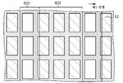
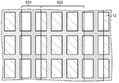
형상에 기인한 무아레가 발생하는 원인이, 투과형 표시 패널과 시차 배리어 사이의 배치 관계를 예시하는 개략도들인 도 28a, 도 28b, 도 29a 및 도 29b를 참조하여 설명될 것이다. 또한, 이들 도면들에서, 편의상, 투과형 표시 패널 및 시차 배리어는 서로 중첩하도록 예시되어 있다. 또한, 시차 배리어의 광 투과부들(131 및 631)이 투과형 표시 패널상에 투영되는 영역에는 좌상(upper left)으로부터 우하(lower right)로 작은 폭을 갖는 해칭이 제공되고, 시차 배리어의 차광부들(132 및 632)이 투과형 표시 패널상에 투영되는 영역에는 우상으로부터 좌하로 중간 폭을 갖는 해칭이 제공된다. 또한, 차광부들(132 및 632)을 중첩하는 부분에는 좌상으로부터 우하로 큰 폭을 갖는 해칭이 제공된다. 이것은 또한 후술하는 도 13에 대해 동일하다. 각 화소는 블랙 매트릭스에 의해 둘러싸인다.The cause of moire due to the shape will be described with reference to FIGS. 28A, 28B, 29A, and 29B, which are schematic diagrams illustrating an arrangement relationship between the transmissive display panel and the parallax barrier. In addition, in these drawings, the transmissive display panel and the parallax barrier are illustrated to overlap each other for convenience. In addition, a hatching having a small width from the upper left to the lower right is provided in the area where the
여기서, 제1 방향으로의 시차 배리어의 광 투과부(131)의 폭이 제1 방향으로의 부화소들의 배열 피치(ND)와 동일한 경우에서(도 28a 참조), 화상을 관찰하는 화상 관찰자의 시점이 제1 방향으로 약간 이동되더라도(도 28b 참조), 차광부들(132)에 의해 커버되지 않은 화소 부분의 면적은 변하지 않는다. 따라서, 화상을 관찰하는 화상 관찰자의 시점이 제1 방향으로 약간 이동되더라도, 화면의 밝기는 변하지 않는다. 따라서, 무아레가 발생하지 않는다.Here, when the width of the
한편, 제1 방향으로의 시차 배리어의 광 투과부(631)의 폭이 제1 방향으로의 부화소들의 배열 피치(ND)와 동일한 경우에(도 29a 참조), 화상을 관찰하는 화상 관찰자의 시점이 제1 방향으로 약간 이동되더라도(도 29b 참조), 차광부들(632)에 의해 커버되지 않은 화소 부분의 면적은 변한다. 따라서, 화상을 관찰하는 화상 관찰자의 시점이 제1 방향으로 약간 이동되면, 화면의 밝기가 변한다. 따라서, 무아레가 발생한다.On the other hand, when the width of the
도 2a는 백 배리어 타입 표시 장치에서 무아레 변조도의 시뮬레이션 결과를 예시한다. 또한, 도 2b는 프런트 배리어 타입 표시 장치에서 무아레 변조도의 시뮬레이션 결과를 예시한다. 또한, 도 2a 및 도 2b에서, 제1 방향으로의 화소들의 배열 피치(ND)가 "1"일 때, 가로축은 제1 방향으로의 광 투과부의 폭(W1)의 값을 나타낸다. 도 2a 및 도 2b에서, "a"는 형상에 기인한 무아레로 인한 무아레 변조도를 나타내고, "b"는 회절 현상에 기인한 무아레로 인한 무아레 변조도를 나타낸다. 또한, 세로 방향은 무아레 변조도를 나타낸다. 여기서, 무아레 변조도는 표시 장치의 표시 화면에서의 무아레로 인한 휘도 변화[즉, (휘도 최대값-휘도 최소값)/(휘도 최대값+휘도 최소값)]에 의해 표시될 수도 있다.2A illustrates a simulation result of a moire modulation degree in a back barrier type display device. 2B illustrates a simulation result of the moire modulation degree in the front barrier type display device. 2A and 2B, when the arrangement pitch ND of the pixels in the first direction is "1", the horizontal axis represents the value of the width W 1 of the light transmitting part in the first direction. 2A and 2B, "a" shows moire modulation due to moire due to shape, and "b" shows moire modulation due to moire due to diffraction phenomenon. In addition, the vertical direction represents the moire modulation degree. Here, the moire modulation degree may be displayed by the luminance change due to moire on the display screen of the display device (that is, (luminance maximum value-luminance minimum value) / (luminance maximum value + luminance minimum value)).
무아레 변조도의 시뮬레이션에서, 공간 코히어런스를 고려한 부분 코히어런스 이론의 조명 계산에 기초하여, 투과형 표시 패널에서의 화소의 형상 및 시차 배리어에서의 광 투과부의 형상을 포함하는 회절 계산이 수행된다.In the simulation of the moire modulation degree, diffraction calculation is performed including the shape of the pixel in the transmissive display panel and the shape of the light transmitting part in the parallax barrier based on the illumination calculation of the partial coherence theory taking into account the spatial coherence.
투과형 표시 패널(10)의 표시 영역(11)에 수직인 방향이 광 전파 축(z)으로서 설정되고, 회절이 광 전파 축(z)을 따라 어떻게 변하는지가 추정된다. 계산 모델에서, 1 축 방향에 대한 제한이 변수들의 분리에 의존하여 제공된다. 도 3b의 개념도에 예시되어 있는 바와 같이, 직사각형 개구(P0)(ξ) 및 직사각형 개구(Px)(x)가 갭(z0 (=Z1)) 만큼 서로 이격된 ξ축 및 X축 상에 놓인다. 백 배리어 타입의 경우에, P0(ξ)는 시차 배리어의 광 투과부에 대응하고, Px(x)는 투과형 표시 패널의 화소에 대응한다. 한편, 프런트 배리어 타입의 경우에서, P0(ξ)는 투과형 표시 패널의 화소에 대응하고, Px(x)는 시차 배리어의 광 투과부에 대응한다. 또한, 화상 관찰 위치(투영 스크린면)로서 u축이 x축으로부터 거리(zi)의 위치에 놓인다. 계산의 목적은 u축 상에서 광 프로파일을 획득하는 것이다. 이 목적이 화상 관찰 위치에서 광 프로파일을 획득하는 것이기 때문에, 화상 관찰 위치의 z축에 수직인 평면을 편의상 투영 스크린면이라 칭한다.The direction perpendicular to the
중심 파장(λ)(아래의 식 (A)에서, 바(bar) "-"가 심볼 "λ"의 위에 적용된 "λ 바"로 표시됨)의 스펙트럼 분포를 갖는 광원이 ξ축상에서 개구(P0(ξ))에 분포되는 등가 광원을 가정하면, 광원의 공간 코히어런스는 μ(Δξ)으로 설정된다. 부분 코히어런스 이론에 기초한 계산에 따라, 스크린상의 강도(I(u))는 스크린상의 상호 강도 (Ji(u,0))를 사용함으로써 아래의 식 (A)에 의해 표현될 수도 있다. 또한, 아래의 식 (A)에서, 심볼 u는 바 "-"가 심볼 "u"의 위에 적용되는 "u 바"에 의해 표시된다.A light source having a spectral distribution of the center wavelength λ (in equation (A) below, bar “-” is indicated by “λ bar” applied above symbol “λ”) has an aperture P on the ξ axis.0Assuming an equivalent light source distributed in (ξ)), the spatial coherence of the light source is set to μ (Δξ). According to the calculation based on the partial coherence theory, the intensity on screen I (u) is the mutual intensity on the screen. (JiBy using (u, 0)), it may be represented by the following formula (A). Further, in the following formula (A), the symbol u is represented by the "u bar" in which the bar "-" is applied above the symbol "u".

여기서, I0는 광 강도를 나타내는 상수를 나타내고, 각각의 변수들, 바 "-"가 심볼(ξ) 위에 적용된 "ξ 바", 바 "-"가 x 위에 적용된 "x 바", 및 "u 바"는, 부분 코히어런스 이론에 기초한 상호 강도가 ξ축 평면, x축 평면, 및 u축 평면 각각에서 규정될 때 2개의 변수들(ξ1, ξ2, x1, x2, u1 및 u2)의 각각의 중심 위치들을 나타내고, Δξ 및 Δx는 2개의 변수들 사이의 차이값들을 나타낸다. 또한, 식 (A)에 기초하여 특정한 화소 및 시차 배리어의 영역으로부터의 광의 분포를 계산하여, 특정한 위치에서 화상 관찰자에 의해 관찰되는 화소들의 광 강도를 정확하게 추정하는 것이 가능하다.Where I 0 represents a constant representing the light intensity, the respective variables, "ξ bar" with bar "-" applied over symbol (ξ), "x bar" with bar "-" applied over x, and "u Bar "is defined as two variables (ξ 1 , ξ 2 , x 1 , x 2 , u 1 when the mutual strength based on the partial coherence theory is defined in the ξ plane, the x axis plane, and the u axis plane, respectively. And u 2 ), respectively, and Δξ and Δx represent the difference values between the two variables. Further, it is possible to accurately estimate the light intensity of the pixels observed by the image observer at a specific position by calculating the distribution of light from the region of the particular pixel and parallax barrier based on equation (A).
여기서, 각 화소로부터의 광에 의한 투영 스크린 평면에서 광 프로파일 계산식 (A)을 사용함으로써, 모든 화소들이 점등되는 경우에(전체적으로, 백색 표시), 방사 휘도 분포를 획득할 수 있다. P(0,n)(ξ)가 각 화소에 대해 조정되고, 화소에 의해 형성된 (아래의 식 (B)에서, 바 "-"가 심볼 "u"의 위에 적용되는 "u 바"에 의해 표시된) 광 프로파일(In(u))이 계산된다. 전체적 백색 점등은 모든 화소들에 의한 조명을 합산함으로써 획득되어서, 아래의 식 (B)로부터 획득될 수 있다.Here, by using the light profile calculation formula (A) in the projection screen plane by the light from each pixel, the emission luminance distribution can be obtained when all the pixels are lit (total white display). P (0, n) (ξ) is adjusted for each pixel and is represented by the "u bar" formed by the pixel (in equation (B) below, bar "-" is applied above symbol "u"). ) Light profile I n (u) is calculated. Global white lighting can be obtained by summing the illumination by all the pixels, and can be obtained from equation (B) below.

실제 계산이 식 (B)에 기초하여 수행되는 예가 도 3a에 예시되어 있다. 7개의 화소들 각각에 기초한 휘도 프로파일(In(u))(도 3a는 4개의 화소들 각각에 기초한 프로파일 "A"를 예시함)이 계산되고, 총 휘도(Itotal(u))가 도 3a에서 "B"에 의해 표시된다. 총 휘도의 휘도 프로파일(광 프로파일)에 주목하면, 휘도 불균일이 각각의 화소들의 중첩 주기보다 높은 주기에서 발생하고, 이것은 투과형 표시 패널(10)의 표시 영역(11)의 특정한 포인트(특정한 슬릿)로부터의 방사 각도 분포 특징이 미세한 각도 의존성을 갖는다는 것을 나타낸다. 또한, 도 3a의 가로축은 u축상의 거리(단위: mm)를 나타내고, 세로축은 I0가 "1.0"일 때 휘도 상대값을 나타낸다. 이러한 휘도 불균일(도 3a, 도 4 및 도 5의 그래프들에서 사다리꼴에 유사한 도면의 상부의 노치된 부분(예를 들어, 도 3a의 "B")을 칭함)은 무아레 변조도에 대응한다.An example in which the actual calculation is performed based on equation (B) is illustrated in FIG. 3A. The luminance profile I n (u) based on each of the seven pixels (FIG. 3A illustrates the profile “A” based on each of the four pixels) is calculated, and the total luminance I total (u) is shown in FIG. It is indicated by "B" in 3a. When attention is paid to the luminance profile (light profile) of the total luminance, luminance unevenness occurs at a period higher than the overlapping period of each pixel, which is from a specific point (specific slit) of the
도 4의 (a) 내지 도 5의 (g)는 회절을 고려한 무아레 변조의 계산 예를 예시한다. 또한, 도 4의 (a) 내지 (l)은 백 배리어 타입 표시 장치에서의 무아레 변조의 계산 결과를 예시하고, 도 5의 (a) 내지 (g)는 프런트 배리어 타입 표시 장치에서의 무아레 변조의 계산 예를 예시한다. 도 4의 (a)는 W1/ND=0.9의 경우를 나타내고, 도 4의 (b)는 W1/ND=1.0의 경우를 나타내고, 도 4의 (c)는 W1/ND=1.1의 경우를 나타내고, 도 4의 (d)는 W1/ND=1.2의 경우를 나타내고, 도 4의 (e)는 W1/ND=1.3의 경우를 나타내고, 도 4의 (f)는 W1/ND=1.4의 경우를 나타내고, 도 4의 (g)는 W1/ND=1.5의 경우를 나타내고, 도 4의 (h)는 W1/ND=1.6의 경우를 나타내고, 도 4의 (i)는 W1/ND=1.7의 경우를 나타내고, 도 4의 (j)는 W1/ND=1.8의 경우를 나타내고, 도 4의 (k)는 W1/ND=2.0의 경우를 나타내며, 도 4의 (l)은 W1/ND=2.1의 경우를 나타낸다. 또한, 도 5의 (a)는 W1/ND=1.1의 경우를 나타내고, 도 5의 (b)는 W1/ND=1.2의 경우를 나타내고, 도 5의 (c)는 W1/ND=1.3의 경우를 나타내고, 도 5의 (d)는 W1/ND=1.4의 경우를 나타내고, 도 5의 (e)는 W1/ND=1.5의 경우를 나타내고, 도 5의 (f)는 W1/ND=1.6의 경우를 나타내며, 도 5의 (g)는 W1/ND=1.7의 경우를 나타낸다. 도 4의 (a) 내지 도 5의 (g)에서, 가로축은 u 축상의 거리를 표현하고, 하나의 눈금(scale)은 1 미터를 나타낸다. 또한, 세로축은 I0가 가 "1.0"일 때 상대 휘도를 표현한다. 또한, 아래의 파라미터들이 계산에 사용된다.4 (a) to 5 (g) illustrate calculation examples of moire modulation in consideration of diffraction. 4A to 4L illustrate the results of calculation of moire modulation in the back barrier type display device, and FIGS. 5A to 5G show moire modulation in the front barrier type display device. An example of a calculation is illustrated. 4 (a) shows the case of W 1 /ND=0.9, FIG. 4 (b) shows the case of W 1 /ND=1.0, and FIG. 4 (c) shows the case of W 1 /ND=1.1. 4 (d) shows a case of W 1 /ND=1.2, FIG. 4 (e) shows a case of W 1 /ND=1.3, and FIG. 4 (f) shows W 1 /. a represents a case of ND = 1.4, Fig. 4 (g) is (h) shows the case of the W 1 /ND=1.5, Figure 4 shows a case of W 1 /ND=1.6, (i) in Fig. 4 4 shows the case of W 1 /ND=1.7, FIG. 4 (j) shows the case of W 1 /ND=1.8, FIG. 4 (k) shows the case of W 1 /ND=2.0, and FIG. 4 (L) in the case of W 1 /ND=2.1. 5A shows the case of W 1 /ND=1.1, FIG. 5B shows the case of W 1 /ND=1.2, and FIG. 5C shows W 1 / ND =. The case of 1.3 is shown, FIG. 5 (d) shows the case of W 1 /ND=1.4, FIG. 5 (e) shows the case of W 1 /ND=1.5, and FIG. 5 (f) shows W 1 shows a /ND=1.6 case, the (g) Figure 5 shows a case of W 1 /ND=1.7. In Figs. 4A to 5G, the horizontal axis represents the distance on the u axis, and one scale represents 1 meter. Further, the vertical axis represents relative luminance when I 0 is "1.0". In addition, the following parameters are used in the calculation.
도 4의 (a) 내지 (l)에 예시된 제1 실시예에 따른 백 배리어 타입 표시 장치Back barrier type display device according to the first embodiment illustrated in FIGS. 4A to 4L
직사각형 개구의 폭 P0(ξ) : 176㎛Width of the rectangular opening P 0 (ξ): 176 μm
직사각형 개구의 피치 P0(ξ) : 176㎛Pitch of Rectangular Opening P 0 (ξ): 176㎛
공간 코히어런스 길이 Δμ : 0.03㎛Space Coherence Length Δμ: 0.03㎛
Px(x)의 폭 : 130㎛Width of P x (x): 130㎛
중심 파장 λ0 : 500nmCenter wavelength λ 0 : 500 nm
갭 z0 : 17.8mmGap z 0 : 17.8mm
zi : 4 mz i : 4 m
도 5의 (a) 내지 (g)에 예시된 종래 기술에서의 프런트 배리어 타입 표시 장치Front barrier type display device in the prior art illustrated in FIGS. 5A to 5G
직사각형 개구의 폭 P0(ξ) : 130㎛Width of rectangular opening P 0 (ξ): 130 μm
직사각형 개구의 피치 P0(ξ) : 176㎛Pitch of Rectangular Opening P 0 (ξ): 176㎛
공간 코히어런스 길이 Δμ : 0.03㎛Space Coherence Length Δμ: 0.03㎛
Px(x)의 폭 : 176㎛Width of P x (x): 176㎛
중심 파장 λ0 : 500nmCenter wavelength λ 0 : 500 nm
갭 z0 : 17.8mmGap z 0 : 17.8mm
zi : 4 mz i : 4 m
또한, Δμ는, 공간 코히어런스 길이라 칭하고, 가로 방향으로 2개의 점들 사이의 거리가 유지되는 거리를 나타낸다. 일례로서, 2개의 점들 사이의 코히어런스를 나타내는 코히어런스 함수 (μ(Δξ))는 광원상의 2개의 점들 사이의 거리(Δξ)를 사용함으로써 μ(Δξ)=exp[-Δξ2/(2·Δμ2)]/(2π)1/2로서 표현될 수도 있다. 이러한 함수는 Δξ이 작으면(즉, 2개의 점들 사이의 거리가 매우 짧으면) 함수가 특정한 일정값 ((1/(2π)1/2))이 되고, Δξ가 Δμ보다 크면 함수가 급속이 작아지는 함수 특성을 갖고, 일반적으로 공간 코히어런스를 나타내는 함수로서 사용된다.In addition, (DELTA) (micro) is called spatial coherence length and shows the distance in which the distance between two points is maintained in the horizontal direction. As an example, the coherence function (μ (Δξ) representing the coherence between two points is given by using the distance (Δξ) between two points on the light source by μ (Δξ) = exp [-Δξ 2 / ( 2 · Δμ 2 )] / (2π) 1/2 . This function is small when Δξ is small (that is, the distance between two points is very short) and the function becomes a certain constant ((1 / (2π) 1/2 )), and when Δξ is larger than Δμ, the function is rapidly smaller. Losing has a function characteristic and is generally used as a function representing spatial coherence.
도 2a로부터, 백 배리어 타입 표시 장치에서, 형상에 기인한 무아레 및 회절 현상에 기인한 무아레에 기초한 무아레 변조도는 W1/ND의 값이 증가하여 "1"이 되면 최소가 된다. 또한, W1/ND의 값이 "1"을 초과하면, 무아레 변조도가 증가하고 그 후 감소한다. 또한, W1/ND의 값이 "2"가 되면, 무아레 변조도가 최소가 된다. 한편, 프런트 배리어 타입 표시 장치에서, 형상에 기인한 무아레에 기초한 무아레 변조도는 W1/ND의 값이 증가하여 "1"이 되면 최소가 된다. 또한, W1/ND의 값이 "1"을 초과하면, 무아레 변조도가 증가하고 그 후 감소한다. 또한, W1/ND의 값이 "2"가 되면, 무아레 변조도가 최소가 된다. 그러나, 회절 현상에 기인한 무아레에 기초한 무아레 변조도는 W1/ND의 값이 증가하여 "1"과 "2" 사이에 놓이면 최소가 된다. 또한, 무아레 변조도는 W1/ND의 값이 그것을 초과하면 증가하지만, W1/ND의 값이 "2"가 되어도 큰 값을 갖는다. 다시 말해, 백 배리어 타입 표시 장치에서, W1/ND의 값이 "1" 또는 "2"일 때, 형상에 기인한 무아레 및 회절 현상에 기인한 무아레 양자가 발생하는 것을 억제할 수 있다. 한편, 프런트 배리어 타입 표시 장치에서, W1/ND의 값이 "1" 또는 "2"일 때, 형상에 기인한 무아레의 발생은 억제될 수 있지만 회절 현상에 기인한 무아레가 발생하는 것을 억제하는 것은 어렵다는 것이 증명되었다.From Fig. 2A, in the back barrier type display device, the moiré modulation degree based on the moire due to the shape and the moire due to the diffraction phenomenon is minimized when the value of W 1 / ND increases and becomes "1". Also, if the value of W 1 / ND exceeds "1", the moire modulation degree increases and then decreases. In addition, when the value of W 1 / ND becomes "2", the moire modulation degree is minimum. On the other hand, in the front barrier type display device, the moire modulation degree based on the moire due to the shape becomes minimum when the value of W 1 / ND increases and becomes "1". Also, if the value of W 1 / ND exceeds "1", the moire modulation degree increases and then decreases. In addition, when the value of W 1 / ND becomes "2", the moire modulation degree is minimum. However, the moire-based moire modulation degree due to the diffraction phenomenon is minimized when the value of W 1 / ND increases and lies between "1" and "2". In addition, the moire modulation degree increases when the value of W 1 / ND exceeds that, but has a large value even when the value of W 1 / ND becomes "2". In other words, in the back barrier type display device, when the value of W 1 / ND is "1" or "2", it is possible to suppress generation of both moire due to shape and moire due to diffraction phenomenon. On the other hand, in the front barrier type display device, when the value of W 1 / ND is "1" or "2", generation of moire due to shape can be suppressed, but generation of moire due to diffraction phenomenon is suppressed. It has proved difficult.
도 6a는 W1이 상이한 시차 배리어들(130)이 실험적으로 생성되어 무아레 변조도가 전체 백색 표시에서의 실제로 측정된 결과를 예시하고, 도 6b는 무아레 변조도가 프런트 배리어 타입 표시 장치에서의 전체 백색 표시에서 실제로 측정된 결과를 예시한다. 도 6a 및 도 6b의 무아레 변조도를 측정한 결과는 도 2a 및 도 2b에 예시된 시뮬레이션 결과들, 특히, 회절 현상에 기인한 무아레에 기초한 무아레 변조도의 시뮬레이션 결과에 실질적으로 일치한다. 즉, 회절 현상에 기인한 무아레가 실제 표시 장치에서 심각하게 발생할 수도 있다는 것이 예상된다. 또한, 무아레의 발생이 프런트 배리어 타입 표시 장치에서도 W1/ND의 값을 최적화함으로써 충분하게 억제될 수 있다는 것을 알 수 있다.FIG. 6A illustrates the results of experimentally generated
백 배리어 타입 표시 장치에서, W1=α·ND 및 W1=2α·ND일 때, 표시 장치를 관찰하는 시야각이 0도로부터 변하면 크로스토크가 어떻게 변하는지가 실제로 측정된다. 또한, 시험에서, 8개의 휘도 프로파일들 및 크로스토크에 기초한 휘도 프로파일들이 획득된다. 도 7a 및 도 7b는 각각 W1=α·ND 및 W1=2α·ND일 때의 결과들을 예시한다. 또한, 도 7a 및 도 7b에서, 8개의 휘도 프로파일들은 "B"로 표시되고, 8개의 휘도 프로파일들이 서로 중첩하도록 보이는 크로스토크의 휘도 프로파일은 "A"로 표시된다. 도 7a 및 도 7b에서, 가로축은 시야각(단위: 도)을 나타내고, 세로축은 상대적 휘도값을 나타내며, 8개의 휘도 파일들(B)의 최대 휘도 값의 평균값은 "1"이다. 도 7a 및 도 7b로부터, W1=α·ND의 경우보다는 W1=2α·ND의 경우에서, 휘도 프로파일(B)과 휘도 프로파일(A) 사이의 휘도차가 크고 크로스토크가 크다는 것을 알 수 있다. In the back barrier type display device, when W 1 = α · ND and W 1 = 2α · ND, it is actually measured how the crosstalk changes when the viewing angle of viewing the display device changes from 0 degrees. In addition, in the test, luminance profiles based on eight luminance profiles and crosstalk are obtained. 7A and 7B illustrate the results when W 1 = α · ND and W 1 = 2α · ND, respectively. In addition, in Figs. 7A and 7B, eight luminance profiles are denoted by "B", and the luminance profile of crosstalk in which the eight luminance profiles appear to overlap each other is denoted by "A". 7A and 7B, the horizontal axis represents a viewing angle (unit: degrees), the vertical axis represents a relative luminance value, and the average value of the maximum luminance values of the eight luminance files B is "1". It can be seen from FIGS. 7A and 7B that the luminance difference between the luminance profile B and the luminance profile A is large and the crosstalk is large in the case of W 1 = 2α · ND rather than in the case of W 1 = α · ND. .
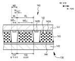
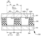
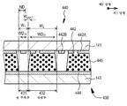
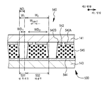
제1 실시예에서, 시차 배리어(130)는 액정 표시 디바이스(140)를 포함한다. 즉, 도 8, 도 9a 및 도 9b의 개략적인 부분 단면도들에 예시되어 있는 바와 같이, 제1 실시예에 따른 표시 장치의 시차 배리어(130)는, 적어도, 제1 기판(141); 제1 기판(141)상에 형성되고 패터닝된 제1 전극(142); 제1 기판(141)과 대향하도록 배치된 제2 기판(143); 제1 전극(142)과 대향하도록 제2 기판(143) 상에 형성된 제2 전극(144); 및 제1 기판(141)과 제2 기판(143) 사이에 개재된 액정층(145)을 포함한다. 시차 배리어(130)의 광 투과부들(131) 및 투과형 표시 패널(10)의 화소들(부화소들)(12)의 배치 상태는 도 28a 및 도 28b에 예시된 바와 동일하다.In the first embodiment, the
투명 전극 재료로 이루어진 패터닝된 제1 전극(142)은 제2 방향으로 연장된다. 한편, 투명 전극 재료로 이루어진 제2 전극(144)은 패터닝되지 않은 소위 플레인 전극이다. 시차 배리어(130)를 형성하는 액정 표시 디바이스(140)의 구성 및 구조는, 화소들 및 부화소들의 구성 및 구조를 제외하고 투과형 표시 패널(10)을 형성하는 액정 표시 패널의 구성 및 구조와 동일하거나 유사하다. 또한, 스위칭 소자, 컬러 필터, 및 블랙 매트릭스가 필요하지 않다.The patterned
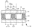
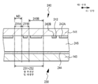
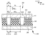
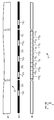
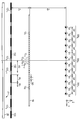
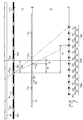
또한, 시차 배리어(130)를 형성하는 액정 표시 디바이스(140)에서, 광 투과부(131) 및 차광부(132)의 세트는 단일 차광부(132)를 형성하는 제1 전극(142A) 및 광 투과부(131)를 형성하는 2개의 제1 전극들(142B)을 포함한다. 또한, 제1 방향으로의 광 투과부(131)의 폭(W1)이 제1 방향으로의 화소들의 배열 피치(ND)와 실질적으로 동일한 경우에(편의상, "제1 경우"로 칭함), 광 투과부(131)는 단일의 제1 전극(142B)을 포함하고, 차광부(132)는 단일의 제1 전극(142A) 및 나머지 하나의 제1 전극(142B)을 포함한다. 한편, 제1 방향으로의 광 투과부(131)의 폭(W1)이 제1 방향으로의 화소들의 배열 피치(ND)의 실질적으로 2배인 경우에(편의상, "제2 경우"로 칭함), 광 투과부(131)는 2개의 제1 전극들(142B)을 포함하고, 차광부(132)는 단일의 제1 전극(142A)을 포함한다. 여기서, 차광부(132)를 형성하는 제1 전극(142A)의 제1 방향으로의 폭(WD21)은 제1 방향으로의 차광부(132)의 폭(W2)보다 작고, 광 투과부(131)를 형성하는 제1 전극(142B)의 제1 방향으로의 폭(WD11)은 제1 방향으로의 광 투과부의 폭(W1)보다 작다. 구체적으로는, 제1 경우에서, W2-WD21=10㎛이고, W1-WD11=10㎛이다(도 7a 참조). 또한, 제2 경우에서도, W2-WD21=10㎛이고, W1-WD11=10㎛이다(도 9b 참조). 또한, 제1 전극(142B)과 제1 전극(142B) 사이의 갭 폭(Wgap -1), 및 제1 전극(142A)과 제1 전극(142B) 사이의 갭 폭(Wgap -2)은 Wgap -1=10㎛이고, Wgap -2=10㎛이다. 제1 방향으로의 차광부의 폭(W1)은 제1 전극(142) 및 제2 전극(144)에 대한 전압의 인가 상태에 의존하여 W1=1.0×ND 또는 W1=2.0×ND로 변경된다(도 9a 및 도 9b 참조). 광 투과부의 폭(W1)이 변경되어서, 투과형 표시 패널(10)에 표시된 화상의 휘도를 증가시킬 수 있다. 시차 배리어(130)를 형성하는 액정 표시 디바이스(140)의 액정층(145)은 전압이 제1 전극(142) 및 제2 전극(144)에 인가되지 않을 때 광을 투과하는 상태(노멀리 화이트) 또는 광을 투과하지 않는 상태(노멀리 블랙)에 있을 수도 있다. 또한, 도 8에 예시된 액정 표시 디바이스(140)의 상태에서, 2차원 화상이 표시될 수 있다.Further, in the liquid
구체적으로는, 상술한 바와 같이, 투과형 표시 패널(10)의 화소 피치(ND)가 0.100mm이고, 거리(Z2)가 1500mm이며, 거리(DP)가 65.0mm이면, 거리(Z1)는 2.31mm이며, 광 투과부 피치(RD)는 0.400mm이다. 여기서, 제1 경우에서, W1=0.100mm 및 W2=0.300mm이거나, 제2 상태에서, W1=0.200mm 및 W2=0.200mm이다. 또한, W11=0.090mm 및 W21=0.190mm이다.Specifically, as described above, when the pixel pitch ND of the
또한, 제1 실시예에서, 투과형 표시 패널(10)의 헤이즈값은 4%이다. 구체적으로는, PET 필름 또는 TAC 필름과 같은 투명 필름(미도시)의 표면에 조면화 처리를 적용함으로써 얻어진 필름, 또는 상이한 굴절률들을 갖는 입자들이 스프레이된 필름이 투과형 표시 패널(10)에 부착될 수도 있다. 이러한 형태는 후술하는 다양한 실시예들에 적용될 수도 있다.In addition, in the first embodiment, the haze value of the
제1 실시예에 따른 표시 장치에서, 입체 화상들 및 2차원 화상들이 표시될 수 있거나, 상이한 각도들로부터 표시 장치를 볼 때 상이한 화상들이 표시될 수 있다. 또한, 제1 실시예에 따른 표시 장치에서, 제1 방향으로의 광 투과부의 폭이 가변이기 때문에서, 표시 장치에 표시된 화상들의 고화질을 요구하는 경우에, 광 투과부의 폭은 작을 수도 있고[W1=α·ND], 고휘도를 요구하는 경우에는, 광 투과부의 폭은 클 수도 있다[W1=2α·ND]. 따라서, 표시 장치에 표시된 화상들의 고화질을 요구하는 경우 및 그 화상들의 고휘도를 요구하는 경우 양자를 적절하게 처리하거나 지원할 수 있다.In the display device according to the first embodiment, stereoscopic images and two-dimensional images may be displayed, or different images may be displayed when viewing the display device from different angles. Further, in the display device according to the first embodiment, since the width of the light transmitting portion in the first direction is variable, when the high quality of the images displayed on the display device is required, the width of the light transmitting portion may be small [W 1 = alpha ND], in the case of requiring high brightness, the width of the light transmitting portion may be large [W 1 = 2 alpha ND]. Therefore, when the high quality of the images displayed on the display device is required and when the high brightness of the images is required, both can be properly processed or supported.
3. 제2 실시예3. Second Embodiment
제2 실시예는 제1 실시예의 변형이다. 제2 실시예에서, 시차 배리어(230)를 형성하는 액정 표시 디바이스(240)의 개략 부분 단면도들인 도 10, 도 11a 및 도 11b에 예시되어 있는 바와 같이, 차광부(232)를 형성하는 액정 표시 디바이스의 영역(240B)에 제1 전극(242A)이 형성된다. 또한, 광 투과부(231)는 제1 전극(242B)이 형성되는 영역(231B) 및 제1 전극(242B)이 형성되지 않는 영역(231A)을 포함하고, 이 영역들은 제1 방향으로 평행하게 배열된다. 또한, 제1 방향으로의 광 투과부(231)의 폭(W1)이 제1 방향으로의 화소들의 배열 피치(ND)와 실질적으로 동일한 경우에(제1 경우), 광 투과부(231)는, 제1 전극이 형성되지 않은 영역(231A)을 포함하고, 차광부(232)는 제1 전극(242A) 및 제1 전극(242B)을 포함한다. 한편, 제1 방향으로의 광 투과부(231)의 폭(W1)이 제1 방향으로의 화소들의 배열 피치(ND)의 실질적으로 2배인 경우에(제2 경우), 광 투과부(231)는, 제1 전극(242B)이 형성된 영역(231B) 및 제1 전극이 형성되지 않은 영역(231A)을 포함하고, 차광부(232)는 제1 전극(242A)을 포함한다. 여기서, 광 투과부(231)를 형성하는 제1 전극(242B)의 제1 방향으로의 폭(WD11)은 제1 방향으로의 광 투과부(231)의 폭(W1)보다 작다. 구체적으로는, 제1 경우에서, W1-WD11=10㎛이다(도 11a 참조). 또한, 제2 경우에서도, W1-WD11=10㎛이다(도 11b 참조). 또한, 제1 전극(242B)과 제1 전극(242A) 사이의 갭 폭(Wgap -2)은 제1 실시예에서와 동일하다. 시차 배리어(230)를 형성하는 액정 표시 디바이스(240)의 액정층(245)은 전압이 제1 전극(242) 및 제2 전극(244)에 인가되지 않을 때 광을 투과하는 상태(노멀리 화이트)에 있다. 또한, 제2 실시예에서도 또한, 제1 방향으로의 차광부(231)의 폭(W1)은 제1 전극(242) 및 제2 전극(244)에 대한 전압의 인가 상태에 의존하여 W1=1.0×ND 또는 W1=2.0×ND로 변경된다(도 11a 및 도 11b 참조). 광 투과부의 폭(W1)이 변경되어서, 투과형 표시 패널(10)에 표시된 화상의 휘도를 증가시킬 수 있다. 또한, 도 10에 예시된 액정 표시 디바이스(240)의 상태에서, 2차원 화상이 표시될 수 있다.The second embodiment is a modification of the first embodiment. In the second embodiment, as illustrated in FIGS. 10, 11A and 11B, which are schematic partial cross-sectional views of the liquid
4. 제3 실시예4. Third embodiment
제3 실시예는 제1 및 제2 실시예들의 변형이다. 도 12는 제3 실시예에 따른 표시 장치가 가상으로 분리될 때의 개략적인 사시도이다. 또한, 도 13은 제3 실시예에 따른 표시 장치의 투과형 표시 패널(10)과 시차 배리어(330) 사이의 배치 관계를 예시하는 개략도이다. 또한, 도 14는 제3 실시예의 변형예에 따른 표시 장치가 가상으로 분리될 때의 개략적인 사시도이다.The third embodiment is a modification of the first and second embodiments. 12 is a schematic perspective view of the display device according to the third embodiment when it is virtually separated. 13 is a schematic diagram illustrating an arrangement relationship between the
제3 실시예에서, 시차 배리어(330)의 축선(AX)과 제2 방향에 의해 형성된 각도(θ)가 예각이고, 시차 배리어(330)의 광 투과부(331) 및 차광부(332)는 제2 방향으로 화소들(12)의 배열 피치가 ND2일 때 θ=tan-1(ND2/ND)을 충족한다. 이 식을 충족함으로써, 화소들(12)과 이 화소들에 대향하는 시차 배리어(330)의 광 투과부들(331) 사이의 위치 관계는 시차 배리어(330)의 축선(AX)의 방향으로 항상 동일하여서, 입체 표시가 수행될 때 크로스토크의 발생을 억제할 수 있고, 고화질의 입체 표시를 실현할 수 있다. 여기서, 도 12 및 도 13에 예시되어 있는 바와 같이, 시차 배리어(330)를 형성하는 광 투과부들(331)은 시차 배리어(330)의 축선(AX)을 따라 직선 형상으로 배열될 수도 있다. 다르게는, 도 14에 예시되어 있는 바와 같이, 시차 배리어(330)를 형성하는 광 투과부들(331)은 시차 배리어(330)의 축선(AX)을 따라 계단 패턴으로 배열될 수도 있다. 즉, 핀 홀-형상(pin hole-shaped)의 광 투과부(개구)가 비스듬하게 연결되도록 배치되어서, 전체적으로 비스듬하게 연장되는 광 투과부들(331)이 구성될 수도 있다. 제3 실시예의 구성 및 구조는 후술하는 제4 및 제5 실시예들의 표시 장치들에 적용될 수도 있다.In the third embodiment, the angle θ formed by the axis AX of the
5. 제4 실시예5. Fourth embodiment
제4 실시예는 또한 제1 실시예의 변형이지만, 제4 실시예에 따른 표시 장치는 구체적으로는 소위 프런트 배리어 타입 표시 장치에 관한 것이다. 도 15는 제4 실시예에 따른 표시 장치가 가상으로 분리될 때의 개략적인 사시도이고, 도 27은 제4 실시예에 따른 표시 장치에서 투과형 표시 패널(10), 시차 배리어(430), 및 면 조명 디바이스(20) 사이의 배치 관계를 예시하는 표시 장치의 개념도이다.The fourth embodiment is also a modification of the first embodiment, but the display device according to the fourth embodiment specifically relates to a so-called front barrier type display device. FIG. 15 is a schematic perspective view of a virtually separated display device according to a fourth embodiment, and FIG. 27 illustrates a
도 15에 예시되어 있는 바와 같이, 제4 실시예에 따른 표시 장치에서, 시차 배리어(430)는 투과형 표시 패널(10)의 전면(front surface) 상에 배치된다. 또한, W1은 W1=α·ND 및 W1=(α+1)·ND의 2개의 값들로 변경된다. 또한, 1<α<2가 충족된다. 구체적으로는, 제4 실시예에서, α는 1.35로 설정된다. 상술한 점들을 제외하고, 제4 실시예에 따른 표시 장치의 구성 및 구조는 제1 실시예에 따른 표시 장치의 구성 및 구조와 기본적으로 동일할 수도 있다.As illustrated in FIG. 15, in the display device according to the fourth embodiment, the
제4 실시예에서도 또한, 표시 장치에 표시된 화상들의 시점들의 수가 도 15에 예시된 각각의 관찰 영역들(WAL, WAC 및 WAR)에서의 4개의 시점들(A1, A2, A3 및 A4)이라고 가정하여 설명이 이루어진다. 그러나, 본 발명은 이에 제한되지 않고, 관찰 영역들 또는 시점들의 수는 표시 장치의 설계들에 따라 적절하게 설정될 수도 있다. 도 27은 도 15에 예시된 관찰 영역들(WAL, WAC 및 WAR)에서의 시점들(A1, A2, A3 및 A4), 투과형 표시 패널(10), 시차 배리어(430), 및 면 조명 디바이스(20) 사이의 배치 관계를 예시하는 개념도이다.Also in the fourth embodiment, the number of viewpoints of the images displayed on the display device is four viewpoints A 1 , A 2 , A in the respective observation regions WA L , WA C and WA R illustrated in FIG. 15. The explanation is made on the assumption that 3 and A 4 ). However, the present invention is not limited thereto, and the number of observation areas or viewpoints may be appropriately set according to the designs of the display device. FIG. 27 illustrates viewpoints A 1 , A 2 , A 3, and A 4 in the observation areas WA L , WA C, and WA R , the
설명의 편의상, 광 투과부들(431)이 X 방향으로 홀수로 평행하게 배열되고, p번째 광 투과부(431p)가 광 투과부(4311)와 광 투과부(431P) 사이의 중앙에 위치한다는 것을 가정한다. 또한, m번째 화소(12m)와 m+1번째 화소(12m+1) 사이의 경계, 및 관찰 영역(WAC)에서 시점들(A2 및 A3) 사이의 중간점은 광 투과부(431p)의 중심을 통해 Z 방향으로 연장되는 가상 직선 상에 위치한다는 것을 가정한다.For convenience of description, the
화소들(12m+3, 12m+2, 12m+1 및 12m)로부터의 광 빔들이 광 투과부(431p)를 통과하고 중앙 관찰 영역(WAC)의 시점들(A1, A2, A3 및 A4)을 향해 이동하는 조건을 고찰한다. 설명의 편의상, 광 투과부(431)의 폭(W1)이 충분하게 작다고 가정하고 광 투과부(431)의 중심을 통과하는 광의 궤도를 주목하여 설명이 이루어질 것이다. 기준으로서 Z 방향으로 광 투과부(431p)의 중심을 통해 연장되는 가상 직선을 사용함으로써, 화소(12m+3)의 중심까지의 거리는 X1로 표시되고, 중심 관찰 영역(WAC)의 시점(A1)까지의 거리는 X2로 표시된다. 화소(12m+3)로부터의 광이 광 투과부(431p)를 통과하여 관찰 영역(WAC)의 시점(A1)을 향해 이동할 때, 아래의 식 (5)로 표시된 조건이 기하학적인 유사성 관계로부터 충족된다.Light beams from the
Z1/X1=Z2/X2 (5)Z 1 / X 1 = Z 2 / X 2 (5)
여기서, X1=1.5×ND이고 X2=1.5×DP이기 때문에, 이들이 반영되면, 식 (5)는 아래의 식 (5')에서와 같이 표현될 수도 있다.Here, since X 1 = 1.5 × ND and X 2 = 1.5 × DP, if they are reflected, equation (5) may be expressed as in equation (5 ') below.
Z1/(1.5×ND)=Z2/(1.5×DP) (5')Z 1 /(1.5×ND)=Z 2 /(1.5×DP) (5 ')
또한, 식 (5')이 충족되면, 광 투과부(431p)를 통과하는 화소들(12m+2, 12m+1 및 12m)로부터의 광 빔들이 관찰 영역(WAC)의 시점들(A2, A3 및 A4)을 향해 각각 이동한다는 것이 기하학적으로 명백하다.Also, if equation (5 ') is satisfied, the light beams from the
다음으로, 화소들(12m-1, 12m, 12m+1 및 12m+2)로부터의 광 빔들이 광 투과부(431p+1)를 통과하고 우측 관찰 영역(WAR)의 시점들(A1, A2, A3 및 A4)을 향해 이동하는 조건을 고찰한다.Next, light beams from the
기준으로서 Z 방향으로 광 투과부(431p+1)의 중심을 통해 연장되는 가상 직선을 사용함으로써, 우측 관찰 영역(WAR)의 시점(A1)까지의 거리는 X3으로 표시된다. 화소(12m+3)로부터의 광이 광 투과부(431p+1)를 통과하여 관찰 영역(WAR)의 시점(A1)을 향해 이동하게 하기 위해, 아래의 식 (6)으로 표시된 조건이 기하학적인 유사성 관계로부터 충족된다.By using an imaginary straight line extending through the center of the light transmitting portion 431 p + 1 in the Z direction as a reference, the distance to the viewpoint A 1 of the right viewing area WA R is represented by X 3 . In order for the light from the
Z1/(RD-X1)=(Z1+Z2)/(X3-X1) (6)Z 1 / (RD-X 1 ) = (Z 1 + Z 2 ) / (X 3 -X 1 ) (6)
여기서, X1=1.5×ND이고 X3=2.5×DP이기 때문에, 이들이 반영되면, 식 (6)은 아래의 식 (6')에서와 같이 표현될 수도 있다.Here, since X 1 = 1.5 × ND and X 3 = 2.5 × DP, if they are reflected, equation (6) may be expressed as in equation (6 ') below.
Z1/(RD-1.5×ND)=(Z1+Z2)/(2.5×DP-1.5×ND) (6')Z 1 /(RD-1.5×ND)=(Z 1 + Z 2 ) / (2.5 × DP-1.5 × ND) (6 ')
또한, 식 (6')이 충족되면, 화소들(12m+2, 12m+1 및 12m) 각각을 통과하는 광 투과부(431p+1)로부터 광 빔들이 관찰 영역(WAR)의 시점들(A2, A3 및 A4)을 향해 이동한다는 것이 기하학적으로 명백하다.Also, if equation (6 ') is satisfied, the light beams from the
거리(Z2) 및 거리(DP)의 값들은 표시 장치의 사양에 기초하여 소정의 값들로 설정된다. 또한, 화소 피치(ND)의 값은 투과형 표시 패널(10)의 구조에 의해 규정된다. 식들 (5') 및 (6')로부터, 아래의 식들 (7) 및 (8)이 거리(Z1) 및 광 투과부 피치(RD)에 관하여 획득될 수 있다.The values of the distance Z 2 and the distance DP are set to predetermined values based on the specification of the display device. In addition, the value of the pixel pitch ND is defined by the structure of the
Z1=Z2×ND/DP (7)Z 1 = Z 2 × ND / DP (7)
RD=4×DP×ND/(DP+ND) (8)RD = 4 × DP × ND / (DP + ND) (8)
상술한 예에서, 광 투과부 피치(RD)의 값은 화소 피치(ND)의 값의 실질적으로 4배이다. 따라서, "M" 및 "P"는 M![]()
![]()
시점들의 수가 상기 설명에서 "4개"이지만, 시점들의 수는 표시 장치의 사양에 따라 적절하게 선택될 수도 있다. 예를 들어, 시점들의 수가 "2개" 또는 시점들의 수가 "6개"인 구성이 있을 수도 있다. 이러한 경우에서, 시차 배리어(430) 등의 구성이 적절하게 변경될 수도 있다. 이것은 또한 후술하는 제5 실시예에 대해 동일하다.Although the number of viewpoints is "four" in the above description, the number of viewpoints may be appropriately selected according to the specification of the display device. For example, there may be a configuration in which the number of viewpoints is "two" or the number of viewpoints is "six". In such a case, the configuration of the
또한, 제4 실시예에 따른 표시 장치에서, 상술한 바와 같이, α가 1 이상의 임의의 계수일 때, W1은 W1=α· ND 및 W1=(α+1)· ND의 2개의 값들로 변경된다. 여기서, 제4 실시예에 따른 표시 장치에서, 상술한 바와 같이, 1<α<2가 충족되고, 더욱 구체적으로는, α=1.35이다. 또한, 표시 장치에서의 화질을 중요시하고, 화상의 휘도를 중요시하지 않은 경우에, W1=α·ND의 형태가 이용될 수도 있고, 반대로, 표시 장치에서의 화상의 휘도를 중요시하고 화질을 중요시하지 않은 경우에, W1=(α+1)·ND의 형태가 이용될 수도 있다. α=1.35를 이용함으로써, 상술한 바와 같이, 무아레의 발생을 억제할 수 있다.In addition, in the display device according to the fourth embodiment, as described above, when α is an arbitrary coefficient of 1 or more, W 1 represents two of W 1 = α · ND and W 1 = (α + 1) · ND. Are changed to values. Here, in the display device according to the fourth embodiment, as described above, 1 <α <2 is satisfied, and more specifically, α = 1.35. In addition, in the case where the image quality in the display device is important and the brightness of the image is not important, the form of W 1 = α · ND may be used. On the contrary, in the display device, the image brightness and the image quality are important. If not, the form W 1 = (α + 1) .ND may be used. By using α = 1.35, generation of moire can be suppressed as described above.
개략적인 부분 단면도들인 도 16, 도 17a 및 도 17b에 예시되어 있는 바와 같이, 제4 실시예에서도, 시차 배리어(430)를 형성하는 액정 표시 디바이스(440)에서, 광 투과부(431) 및 차광부(432)의 세트는 단일 차광부(432)를 형성하는 제1 전극(442A) 및 광 투과부(431)를 형성하는 2개의 제1 전극(442B)을 포함한다. 또한, 제1 방향으로의 광 투과부(431)의 폭(W1)이 [α· ND]인 경우에(제1 경우), 광 투과부(431)는 단일의 제1 전극(442B)을 포함하고, 차광부(432)는 단일의 제1 전극(442A) 및 나머지 하나의 제1 전극(442B)을 포함한다. 한편, 제1 방향으로의 광 투과부(431)의 폭(W1)이 [(α+1)· ND]인 경우에(제2 경우), 광 투과부(431)는 2개의 제1 전극들(442B)을 포함하고, 차광부(432)는 단일의 제1 전극(442A)을 포함한다. 여기서, 차광부(432)를 형성하는 제1 전극(442A)의 제1 방향으로의 폭(WD21)은 제1 방향으로의 차광부(432)의 폭(W2)보다 작고, 광 투과부(431)를 형성하는 제1 전극(442B)의 제1 방향으로의 폭(WD11)은 제1 방향으로의 광 투과부의 폭(W1)보다 작다. 구체적으로는, 제1 경우에서, W2-WD21=10㎛이고, W1-WD11=10㎛이다(도 17a 참조). 또한, 제2 경우에서도, W2-WD21=10㎛이고, W1-WD11=10㎛이다(도 17b 참조). 또한, 제1 전극(442B)과 제1 전극(442B) 사이의 갭 폭(Wgap -1), 및 제1 전극(442A)과 제1 전극(442B) 사이의 갭 폭(Wgap -2)은 Wgap -1=10㎛이고, Wgap -2=10㎛이다. 제1 방향으로의 광 투과부의 폭(W1)은 제1 전극(442) 및 제2 전극(444)에 대한 전압의 인가 상태에 의존하여 [α·ND] 또는 [(α+1)·ND]로 변경된다(도 17a와 도 17b 참조). 광 투과부의 폭(W1)이 변경되어서, 투과형 표시 패널(10)에 표시된 화상의 휘도를 증가시킬 수 있다. 시차 배리어(430)를 형성하는 액정 표시 디바이스(440)의 액정층(445)은, 전압이 제1 전극(442) 및 제2 전극(444)에 인가되지 않을 때 광을 투과하는 상태(노멀리 화이트) 또는 광을 투과하지 않는 상태(노멀리 블랙)에 있을 수도 있다. 또한, 도 16에 예시된 액정 표시 디바이스(440)의 상태에서, 2차원 화상이 표시될 수 있다.As illustrated in the schematic partial cross-sectional views of FIGS. 16, 17A, and 17B, in the fourth embodiment, in the liquid
구체적으로는, 상술한 바와 같이, 투과형 표시 패널(10)의 화소 피치(ND)가 0.100mm이고, 거리(Z2)가 1500mm이며, 거리(DP)가 65.0mm이면, 거리(Z1)는 2.31mm이며, 광 투과부 피치(RD)는 0.399mm이다. 여기서, W1=0.135mm및 W2=0.264mm이거나, W1=0.235mm 및 W2=0.164mm이다. 또한, W11=0.125mm 및 W21=0.225mm이다.Specifically, as described above, when the pixel pitch ND of the
또한, 제4 실시예에서, 시차 배리어(430)의 헤이즈값은 4%이다. 구체적으로는, PET 필름 또는 TAC 필름과 같은 투명 필름(미도시)의 표면에 조면화 처리를 적용함으로써 얻어진 필름, 또는 상이한 굴절률들을 갖는 입자들이 스프레이된 필름이 시차 배리어(430)에 부착될 수도 있다. 이러한 형태는 후술하는 실시예들에 적용될 수도 있다.Also, in the fourth embodiment, the haze value of the
제4 실시예에 따른 표시 장치에서도, 입체 화상들 및 2차원 화상들이 표시될 수 있거나, 상이한 각도들로부터 표시 장치를 볼 때 상이한 화상들이 표시될 수 있다. 또한, 제4 실시예에 따른 표시 장치에서도, 제1 방향으로의 광 투과부의 폭이 가변이기 때문에, 표시 장치에 표시된 화상들의 고화질을 요구하는 경우에는 광 투과부의 폭이 작을 수도 있고[W1=α·ND], 고휘도를 요구하는 경우에는 광 투과부의 폭이 클 수도 있다[W1=(α+1)·ND]. 따라서, 표시 장치에 표시된 화상들의 고화질을 요구하는 경우 및 그 화상들의 고휘도를 요구하는 경우 양자를 적절하게 처리하거나 지원할 수 있다.Also in the display device according to the fourth embodiment, stereoscopic images and two-dimensional images may be displayed, or different images may be displayed when viewing the display device from different angles. Further, even in the display device according to the fourth embodiment, since the width of the light transmitting portion in the first direction is variable, the width of the light transmitting portion may be small when high image quality of images displayed on the display device is required [W 1 = α · ND], if required, the high brightness may be larger that the width of the light transmission [W 1 = (α + 1 ) · ND]. Therefore, when the high quality of the images displayed on the display device is required and when the high brightness of the images is required, both can be properly processed or supported.
6. 제5 실시예6. Fifth Embodiment
제5 실시예는 제4 실시예의 변형이다. 제5 실시예에서, 시차 배리어(530)를 형성하는 액정 표시 디바이스(540)의 개략적인 부분 단면도들인 도 18, 도 19a 및 도 19b에 예시되어 있는 바와 같이, 차광부(532)를 형성하는 액정 표시 디바이스의 영역(540B)에 제1 전극(542A)이 형성된다. 또한, 광 투과부(531)는 제1 전극(542B)이 형성되는 영역(531B) 및 제1 전극이 형성되지 않는 영역(531A)을 포함하고, 이 영역들은 제1 방향으로 평행하게 배열된다. 또한, 제1 방향으로의 광 투과부(531)의 폭(W1)이 [α·ND]인 경우에(제1 경우), 광 투과부(531)는 제1 전극이 형성되지 않은 영역(531A)을 포함하고, 차광부(532)는 제1 전극(542A) 및 제1 전극(542B)을 포함한다. 한편, 제1 방향으로의 광 투과부(531)의 폭(W1)이 [(α+1)·ND]인 경우에서(제2 경우), 광 투과부(531)는, 제1 전극(542B)이 형성된 영역(531B) 및 제1 전극이 형성되지 않은 영역(531A)을 포함하고, 차광부(532)는 제1 전극(542A)을 포함한다. 여기서, 광 투과부(531)를 형성하는 제1 전극(542B)의 제1 방향으로의 폭(WD11)은 제1 방향으로의 광 투과부(531)의 폭(W1)보다 작다. 구체적으로는, 제1 경우에서, W1-WD11=10㎛이다(도 19a 참조). 또한, 제2 경우에서도, W1-WD11=10㎛이다(도 19b 참조). 또한, 제1 전극(542A)과 제1 전극(542B) 사이의 갭 폭(Wgap -2)은 제4 실시예에서와 동일하다. 시차 배리어(530)를 형성하는 액정 표시 디바이스(540)의 액정층(545)은 전압이 제1 전극(542) 및 제2 전극(544)에 인가되지 않을 때 광을 투과하는 상태(노멀리 화이트)에 있다. 또한, 제5 실시예에서도, 제1 방향으로의 차광부(531)의 폭(W1)은 제1 전극(542) 및 제2 전극(544)에 대한 전압의 인가 상태에 의존하여 W1=α·ND 또는 W1=(α+1)·ND로 변경된다(도 19a 및 도 19b 참조). 광 투과부의 폭(W1)이 변경되어서, 투과형 표시 패널(10)에 표시된 화상의 휘도를 증가시킬 수 있다. 또한, 도 18에 예시된 액정 표시 디바이스(540)의 상태에서, 2차원 화상이 표시될 수 있다.The fifth embodiment is a modification of the fourth embodiment. In the fifth embodiment, as illustrated in FIGS. 18, 19A, and 19B, which are schematic partial cross-sectional views of the liquid
상기와 같이, 본 발명이 실시예들에 기초하여 설명되었지만, 본 발명은 이 실시예들에 제한되지 않는다. 실시예들에 설명한 투과형 표시 패널, 면 조명 디바이스, 및 시차 배리어의 구성들 및 구조들은 예들이고 적절하게 변형될 수도 있다. 예를 들어, 크고, 작은, 크고, 작은, …제1 방향으로의 블랙 매트릭스의 폭과 같은 큰 폭을 갖는 블랙 매트릭스가 2개의 부화소들마다 형성되는 투과형 표시 패널이 존재한다. 다시 말해, 블랙 매트릭스는 2개의 부화소들의 주기 구조를 갖는다. 이러한 투과형 표시 패널을 갖는 표시 장치, 예를 들어, 제1 실시예에 따른 표시 장치에서, α의 값은 각 실시예에 설명한 α의 값의 2배일 수도 있다.As mentioned above, although the present invention has been described based on the embodiments, the present invention is not limited to these embodiments. The configurations and structures of the transmissive display panel, surface illumination device, and parallax barrier described in the embodiments are examples and may be modified as appropriate. For example, big, small, big, small,… There is a transmissive display panel in which a black matrix having a large width equal to the width of the black matrix in the first direction is formed every two subpixels. In other words, the black matrix has a periodic structure of two subpixels. In a display device having such a transmissive display panel, for example, the display device according to the first embodiment, the value of α may be twice the value of α described in each embodiment.
또한, 본 발명은 아래의 구성들로서 구현될 수도 있다. 하나의 예시적인 구성에서, 표시 장치는 제1 방향 및 그 제1 방향과 상이한 제2 방향으로 2차원 매트릭스로 배열된 화소들을 포함하는 투과형 표시 패널; 및 투과형 표시 패널에 표시된 화상들을 복수의 시점용의 화상들로 분리하는 시차 배리어를 포함하고, 시차 배리어 및 투과형 표시 패널은 소정의 갭의 공간을 갖고 서로 대향하도록 배치되고, 시차 배리어는 제2 방향에 평행한 축선 또는 제2 방향 방향과 예각을 형성하는 축선을 따라 연장하고 제1 방향으로 교대로 평행하게 배열되는 복수의 광 투과부 및 복수의 차광부를 포함하고, 제1 방향으로의 광 투과부의 폭은 가변이다.In addition, the present invention may be implemented as the following configurations. In one exemplary configuration, a display device includes: a transmissive display panel including pixels arranged in a two-dimensional matrix in a first direction and a second direction different from the first direction; And a parallax barrier that separates the images displayed on the transmissive display panel into a plurality of images for viewpoints, wherein the parallax barrier and the transmissive display panel are arranged to face each other with a space of a predetermined gap, and the parallax barrier is in a second direction. A plurality of light transmitting portions and a plurality of light blocking portions extending along an axis parallel to the axis or forming an acute angle with the second direction and alternately arranged in parallel in the first direction, the width of the light transmitting portion in the first direction Is variable.
시차 배리어는, 적어도, 제1 기판; 제1 기판 상에 형성되고 패터닝된 제1 전극; 제1 기판과 대향하도록 배치된 제2 기판; 제1 전극과 대향하도록 제2 기판 상에 형성된 제2 전극; 및 제1 기판과 제2 기판 사이에 개재된 액정층을 포함하는 액정 표시 디바이스를 가질 수도 있다.The parallax barrier includes at least a first substrate; A first electrode formed and patterned on the first substrate; A second substrate disposed to face the first substrate; A second electrode formed on the second substrate so as to face the first electrode; And a liquid crystal layer interposed between the first substrate and the second substrate.
표시 장치는 배면으로부터 투과형 표시 장치를 조사하는 면 조명 디바이스를 포함할 수도 있고, 시차 배리어는 투과형 표시 패널과 면 조명 디바이스 사이에 배치된다.The display device may include a surface illumination device that irradiates the transmissive display device from the back side, and the parallax barrier is disposed between the transmissive display panel and the surface illumination device.
제1 방향으로의 광 투과부의 폭이 W1이고, 제1 방향으로의 화소들의 배열 피치가 ND이며, α가 임의의 계수이면, W1은 W1=α·ND 및 W1=2α·ND의 2개의 값들로 변경될 수도 있다. 또한, 0.95≤α≤1.05가 충족될 수도 있다. 투과형 표시 패널의 헤이즈 값은 15% 이하일 수도 있다. 예를 들어, 시차 배리어는 투과형 표시 패널의 전면에 배치될 수도 있다.If the width of the light transmitting portion in the first direction is W 1 , the arrangement pitch of the pixels in the first direction is ND, and α is an arbitrary coefficient, then W 1 is W 1 = α · ND and W 1 = 2α · ND It may be changed to two values of. Further, 0.95 ≦ α ≦ 1.05 may be satisfied. The haze value of the transmissive display panel may be 15% or less. For example, the parallax barrier may be disposed in front of the transmissive display panel.
제1 방향으로의 광 투과부의 폭이 W1이고, 제1 방향으로의 화소들의 배열 피치가 ND이며, α가 1 이상의 임의의 계수이면, W1은 W1=α·ND 및 W1=(α+1)·ND의 2개의 값들로 변경될 수도 있다. 또한, 1<α<2가 충족될 수도 있다. 시차 배리어의 헤이즈 값은 15% 이하일 수도 있다.If the width of the light transmitting part in the first direction is W 1 , the arrangement pitch of the pixels in the first direction is ND, and α is any coefficient of 1 or more, then W 1 is W 1 = α · ND and W 1 = ( It may be changed to two values of? +1) .ND. 1 <α <2 may also be satisfied. The haze value of the parallax barrier may be 15% or less.
차광부를 형성하는 제1 전극의 제1 방향으로의 폭은, 예를 들어, 제1 방향으로의 차광부의 폭보다 작을 수도 있다. The width | variety in the 1st direction of the 1st electrode which forms a light shielding part may be smaller than the width | variety of the light shielding part in a 1st direction, for example.
광 투과부를 형성하는 제1 전극의 제1 방향으로의 폭은 제1 방향으로의 광 투과부의 폭보다 작을 수도 있다.The width in the first direction of the first electrode forming the light transmitting part may be smaller than the width of the light transmitting part in the first direction.
제1 방향으로의 광 투과부의 폭은 제1 전극 및 제2 전극에 대한 전압의 인가 상태에 의존하여 변할 수도 있다.The width of the light transmitting portion in the first direction may vary depending on the application state of the voltage to the first electrode and the second electrode.
제1 전극은 차광부를 형성하는 액정 표시 디바이스의 영역에 형성될 수도 있고, 광 투과부는, 제1 방향으로 평행하게 배열되는, 제1 전극이 형성되는 영역 및 제1 전극이 형성되지 않는 영역을 포함할 수도 있고, 광 투과부를 형성하는 제1 전극의 제1 방향으로의 폭은 제1 방향으로의 광 투과부의 폭보다 작을 수도 있다. 제1 방향으로의 광 투과부의 폭은 제1 전극 및 제2 전극에 대한 전압의 인가 상태에 의존하여 변할 수도 있다.The first electrode may be formed in an area of the liquid crystal display device forming the light shielding part, and the light transmitting part includes an area in which the first electrode is formed and an area in which the first electrode is not formed, arranged in parallel in the first direction. The width of the first electrode forming the light transmitting part in the first direction may be smaller than the width of the light transmitting part in the first direction. The width of the light transmitting portion in the first direction may vary depending on the application state of the voltage to the first electrode and the second electrode.
시차 배리어의 축선과 제2 방향에 의해 형성된 각도(θ)는 예각일 수도 있고, 제2 방향으로의 화소들의 배열 피치가 ND2일 때 θ=tan-1(ND2/ND)가 충족될 수도 있다.The angle θ formed by the axis of the parallax barrier and the second direction may be an acute angle, and θ = tan −1 (ND 2 / ND) may be satisfied when the arrangement pitch of the pixels in the second direction is ND 2. have.
시차 배리어의 축선과 제2 방향에 의해 형성된 각도(θ)는 예각일 수도 있고, 시차 배리어를 형성하는 광 투과부들은 시차 배리어의 축선을 따라 직선 형상으로 배열될 수도 있다.The angle θ formed by the axis of the parallax barrier and the second direction may be an acute angle, and the light transmitting portions forming the parallax barrier may be arranged in a straight line along the axis of the parallax barrier.
시차 배리어의 축선과 제2 방향에 의해 형성된 각도(θ)는 예각일 수도 있고, 시차 배리어를 형성하는 광 투과부들은 시차 배리어의 축선을 계단 패턴으로 배열될 수도 있다.The angle θ formed by the axis of the parallax barrier and the second direction may be an acute angle, and the light transmitting portions forming the parallax barrier may be arranged in a staircase pattern along the axis of the parallax barrier.
다른 예시적인 구성에서, 표시 장치는 복수의 화소를 포함하는 표시 패널; 및 복수의 광 투과부 및 복수의 차광부를 포함하는 시차 배리어를 포함하고, 표시 장치는 복수의 광 투과부 중 적어도 하나가 제1 폭을 갖는 제1 세팅과 복수의 광 투과부 중 적어도 하나가 제1 폭과는 상이한 제2 폭을 갖는 제2 세팅 사이에서 스위칭하도록 동작가능하다. In another exemplary configuration, a display device includes a display panel including a plurality of pixels; And a parallax barrier including a plurality of light transmitting parts and a plurality of light blocking parts, wherein the display device includes: a first setting having at least one of the plurality of light transmitting parts having a first width and at least one of the plurality of light transmitting parts having a first width; Is operable to switch between second settings having different second widths.
복수의 화소의 제1 방향 및 제2 방향을 따라 어레이로 배열될 수도 있다. 복수의 화소의 각각은 중심을 가질 수도 있고, 2개의 화소의 중심들 사이의 제1 방향으로 측정된 거리는 표시 패널의 화소 피치를 정의할 수도 있으며, 제2 폭은 화소 피치를 초과할 수도 있다.The pixels may be arranged in an array along first and second directions of the plurality of pixels. Each of the plurality of pixels may have a center, a distance measured in the first direction between the centers of two pixels may define a pixel pitch of the display panel, and the second width may exceed the pixel pitch.
표시 패널의 화소 피치는 ND일 수도 있고, α는 임의의 계수일 수도 있고, 제1 폭은 ND와 α의 곱(product)일 수도 있으며, 제2 폭은 ND와 2α의 곱일 수도 있다. The pixel pitch of the display panel may be ND, α may be an arbitrary coefficient, the first width may be a product of ND and α, and the second width may be a product of ND and 2α.
표시 패널의 화소 피치는 ND일 수도 있고, α는 1 이상의 임의의 계수일 수도 있고, 제1 폭은 ND와 α의 곱일 수도 있으며, 제2 폭은 ND와 (α+1)의 곱일 수도 있다. The pixel pitch of the display panel may be ND, α may be one or more arbitrary coefficients, the first width may be a product of ND and α, and the second width may be a product of ND and (α + 1).
제1 방향은 실질적으로 수평일 수도 있고, 제2 방향은 실질적으로 수직일 수도 있다. The first direction may be substantially horizontal and the second direction may be substantially vertical.
복수의 광 투과부 중 적어도 일부는 제2 방향에 실질적으로 평행하거나 제2 방향에 대해 예각에 있는 축선을 따라 연장되는 길이를 가질 수도 있다. At least some of the plurality of light transmitting portions may have a length extending along an axis substantially parallel to the second direction or at an acute angle with respect to the second direction.
시차 배리어는 제1 전극 및 제2 전극을 포함할 수도 있고, 표시 장치는 제1 전극 및 제2 전극에 대한 전압의 인가를 통해 제1 세팅과 제2 세팅 사이에서 스위칭하도록 동작가능할 수도 있다. 차광부들 중 적어도 하나는 제1 전극이 형성되는 시차 배리어의 영역에 상주할 수도 있고, 적어도 하나의 광 투과부는 제1 전극이 형성되는 시차 배리어의 영역에 상주하는 제1 부분 및 제1 전극이 형성되지 않는 시차 배리어의 영역에 상주하는 제2 부분을 포함할 수도 있고, 그 적어도 하나의 광 투과부의 폭은 제1 전극 및 제2 전극에 대한 전압의 인가에 의존하여 변할 수도 있다.The parallax barrier may comprise a first electrode and a second electrode, and the display device may be operable to switch between the first setting and the second setting through the application of a voltage to the first electrode and the second electrode. At least one of the light blocking portions may reside in an area of the parallax barrier in which the first electrode is formed, and the at least one light transmitting part is formed of a first portion and a first electrode which reside in an area of the parallax barrier in which the first electrode is formed. A second portion residing in an area of the parallax barrier that is not provided may be included, and the width of the at least one light transmitting portion may vary depending on the application of a voltage to the first electrode and the second electrode.
표시 장치는 제1 세팅과 제2 세팅 사이에서 표시 장치를 스위칭하도록 사용자에 의해 조작가능한 체인지오버 스위치를 포함할 수도 있다. The display device may include a changeover switch operable by the user to switch the display device between the first setting and the second setting.
표시 장치는 화상 데이터의 분석에 기초하여 제1 세팅과 제2 세팅 사이에서 표시 장치를 스위칭하도록 동작가능한 화상 신호 처리 유닛을 포함할 수도 있다. The display device may include an image signal processing unit operable to switch the display device between the first setting and the second setting based on the analysis of the image data.
표시 패널은 투과형 표시 패널을 포함할 수도 있다. The display panel may include a transmissive display panel.
표시 장치는 투과형 표시 패널을 광으로 조사하기 위한 면 조명 디바이스를 포함할 수도 있고, 시차 배리어는 면 조명 디바이스와 투과형 표시 패널 사이에 상주할 수도 있다. The display device may include a surface illumination device for irradiating the transmissive display panel with light, and the parallax barrier may reside between the surface illumination device and the transmissive display panel.
표시 패널은 관찰 위치로부터 관찰가능하고, 시차 배리어는 표시 패널과 관찰 위치 사이에 상주할 수도 있다. The display panel is observable from the viewing position, and the parallax barrier may reside between the display panel and the viewing position.
복수의 차광부는 복수의 시점의 각각으로부터 가시적인 화상들을 정의할 수도 있다. The plurality of light blocking portions may define images that are visible from each of the plurality of viewpoints.
시차 배리어 및 표시 패널은 갭만큼 분리될 수도 있다. The parallax barrier and the display panel may be separated by a gap.
표시 장치는 예를 들어, 입체 화상 표시 장치를 포함할 수도 있다. 그러한 경우에, 표시 장치는 육안형 입체 화상 표시 장치를 포함할 수도 있다. The display device may include, for example, a stereoscopic image display device. In such a case, the display device may include a visual stereoscopic image display device.
또 다른 예시적인 구성에서, 전자 디바이스는 복수의 화소를 포함하는 표시 패널; 및 복수의 광 투과부 및 복수의 차광부를 포함하는 시차 배리어를 포함하고, 전자 장치는 복수의 광 투과부 중 적어도 하나가 제1 폭을 갖는 제1 세팅과 복수의 광 투과부 중 적어도 하나가 제1 폭과는 상이한 제2 폭을 갖는 제2 세팅 사이에서 스위칭하도록 동작가능하다. In another exemplary configuration, an electronic device includes a display panel including a plurality of pixels; And a parallax barrier including a plurality of light transmitting parts and a plurality of light blocking parts, wherein the electronic device includes at least one of a first setting having a first width and at least one of the plurality of light transmitting parts having a first width; Is operable to switch between second settings having different second widths.
본 발명은, 그 전체 내용이 참조로 여기에 원용되는 2012년 1월 5일 일본 특허청에 출원된 일본 특허 출원 JP 2012-000624에 개시된 바에 관한 내용을 포함한다.This invention includes the content as disclosed in Japanese Patent Application JP 2012-000624 for which it applied to Japan Patent Office on January 5, 2012, the whole content is taken in here as a reference.
다양한 변형예들, 조합들, 서브-조합들 및 변경예들이 첨부한 청구항들의 범위 또는 그들의 등가물 내에 있는 한, 설계 요건들 및 다른 요인들에 의존하여 발생할 수도 있다는 것이 당업자는 이해해야 한다.It should be understood by those skilled in the art that various modifications, combinations, sub-combinations and variations may occur depending on design requirements and other factors, as long as they are within the scope of the appended claims or their equivalents.
Claims (18)
복수의 화소를 포함하는 표시 패널; 및
복수의 광 투과부 및 복수의 차광부를 포함하는 시차 배리어(parallax barrier)를 포함하고,
상기 표시 장치는 상기 복수의 광 투과부 중 적어도 하나가 제1 폭을 갖는 제1 세팅과 상기 복수의 광 투과부 중 상기 적어도 하나가 상기 제1 폭과는 상이한 제2 폭을 갖는 제2 세팅 사이에서 스위칭하도록 동작가능한, 표시 장치.As a display device,
A display panel including a plurality of pixels; And
A parallax barrier including a plurality of light transmitting parts and a plurality of light blocking parts,
The display device switches between a first setting of which at least one of the plurality of light transmitting parts has a first width and a second setting of which at least one of the plurality of light transmitting parts has a second width different from the first width. Display device operable to operate.
상기 복수의 화소는 제1 방향 및 제2 방향을 따라 어레이로 배열되고, 상기 복수의 화소의 각각은 중심을 갖고, 2개의 화소의 중심들 사이의 상기 제1 방향으로 측정된 거리가 상기 표시 패널의 화소 피치를 정의하며, 상기 제2 폭은 상기 화소 피치를 초과하는, 표시 장치.The method of claim 1,
The plurality of pixels are arranged in an array along a first direction and a second direction, each of the plurality of pixels having a center, and a distance measured in the first direction between centers of two pixels is measured in the display panel. A pixel pitch, wherein the second width exceeds the pixel pitch.
상기 표시 패널의 상기 화소 피치는 ND이고, α는 임의의 계수이고, 상기 제1 폭은 ND와 α의 곱(product)이며, 상기 제2 폭은 ND와 2α의 곱인, 표시 장치.The method of claim 2,
Wherein the pixel pitch of the display panel is ND, α is an arbitrary coefficient, the first width is a product of ND and α, and the second width is a product of ND and 2α.
상기 표시 패널의 상기 화소 피치는 ND이고, α는 1 이상의 임의의 계수이고, 상기 제1 폭은 ND와 α의 곱이며, 상기 제2 폭은 ND와 (α+1)의 곱인, 표시 장치.The method of claim 2,
Wherein the pixel pitch of the display panel is ND, α is an arbitrary coefficient of one or more, the first width is a product of ND and α, and the second width is a product of ND and (α + 1).
상기 제1 방향은 실질적으로 수평이고, 상기 제2 방향은 실질적으로 수직인, 표시 장치.The method of claim 2,
And the first direction is substantially horizontal, and the second direction is substantially vertical.
상기 복수의 광 투과부 중 적어도 일부는 상기 제2 방향에 실질적으로 평행하거나 상기 제2 방향에 대해 예각에 있는 축선을 따라 연장되는 길이를 갖는, 표시 장치.The method of claim 5,
At least some of the plurality of light transmitting portions have a length extending along an axis substantially parallel to the second direction or at an acute angle with respect to the second direction.
상기 시차 배리어는 제1 전극 및 제2 전극을 포함하고, 상기 표시 장치는 상기 제1 전극 및 상기 제2 전극에 대한 전압 인가를 통해 상기 제1 세팅과 상기 제2 세팅 사이에서 스위칭하도록 동작가능한, 표시 장치.The method of claim 2,
The parallax barrier comprises a first electrode and a second electrode, and the display device is operable to switch between the first setting and the second setting via voltage application to the first electrode and the second electrode, Display device.
상기 차광부들 중 적어도 하나는 상기 제1 영역이 형성되는 상기 시차 배리어의 영역에 상주하고, 상기 적어도 하나의 광 투과부는 상기 제1 전극이 형성되는 상기 시차 배리어의 영역에 상주하는 제1 부분 및 상기 제1 전극이 형성되지 않은 상기 시차 배리어의 영역에 상주하는 제2 부분을 포함하고, 상기 적어도 하나의 광 투과부의 폭은 상기 제1 전극 및 상기 제2 전극에 대한 상기 전압의 인가에 의존하여 변하는, 표시 장치.The method of claim 7, wherein
At least one of the light blocking portions resides in a region of the parallax barrier in which the first region is formed, and the at least one light transmitting portion resides in a region of the parallax barrier in which the first electrode is formed, and the And a second portion residing in an area of the parallax barrier where no first electrode is formed, wherein the width of the at least one light transmitting portion varies depending on the application of the voltage to the first electrode and the second electrode. , Display device.
상기 제1 세팅과 상기 제2 세팅 사이에서 상기 표시 장치를 스위칭하도록 사용자에 의해 조작가능한 체인지오버 스위치(changeover switch)를 포함하는, 표시 장치.The method of claim 1,
And a changeover switch operable by the user to switch the display device between the first setting and the second setting.
화상 데이터의 분석에 기초하여 상기 제1 세팅과 상기 제2 세팅 사이에서 상기 표시 장치를 스위칭하도록 동작가능한 화상 신호 처리 유닛을 포함하는, 표시 장치.The method of claim 1,
And an image signal processing unit operable to switch the display device between the first setting and the second setting based on analysis of image data.
상기 표시 패널은 투과형 표시 패널인, 표시 장치.The method of claim 1,
The display panel is a transmissive display panel.
상기 투과형 표시 패널을 광으로 조사하기 위한 면 조명 디바이스를 포함하고, 상기 시차 배리어는 상기 면 조명 디바이스와 상기 투과형 표시 패널 사이에 상주하는, 표시 장치.The method of claim 11,
And a surface illuminating device for irradiating the transmissive display panel with light, wherein the parallax barrier resides between the surface illuminating device and the transmissive display panel.
상기 표시 패널은 관찰 위치로부터 관찰가능하고, 상기 시차 배리어는 상기 표시 패널과 상기 관찰 위치 사이에 상주하는, 표시 장치.The method of claim 1,
And the display panel is observable from an observation position, and the parallax barrier resides between the display panel and the observation position.
상기 복수의 차광부는 복수의 시점의 각각으로부터 가시적인 화상들을 정의하는, 표시 장치.The method of claim 1,
And the plurality of light blocking portions define images visible from each of a plurality of viewpoints.
상기 시차 배리어 및 상기 표시 패널은 갭 만큼 분리되는, 표시 장치.The method of claim 1,
And the parallax barrier and the display panel are separated by a gap.
입체 화상 표시 장치를 포함하는, 표시 장치.The method of claim 1,
A display device comprising a stereoscopic image display device.
육안형(naked eye type) 입체 화상 표시 장치를 포함하는, 표시 장치.17. The method of claim 16,
A display device comprising a naked eye type stereoscopic image display device.
복수의 화소를 포함하는 표시 패널; 및
복수의 광 투과부 및 복수의 차광부를 포함하는 시차 배리어를 포함하고,
상기 전자 디바이스는 상기 복수의 광 투과부 중 적어도 하나가 제1 폭을 갖는 제1 세팅과 상기 복수의 광 투과부 중 상기 적어도 하나가 상기 제1 폭과는 상이한 제2 폭을 갖는 제2 세팅 사이에서 스위칭하도록 동작가능한, 전자 디바이스.As an electronic device,
A display panel including a plurality of pixels; And
A parallax barrier comprising a plurality of light transmitting parts and a plurality of light blocking parts,
The electronic device switches between a first setting wherein at least one of the plurality of light transmitting portions has a first width and a second setting wherein the at least one of the plurality of light transmitting portions has a second width different from the first width. An electronic device operable to.
Applications Claiming Priority (2)
| Application Number | Priority Date | Filing Date | Title |
|---|---|---|---|
| JPJP-P-2012-000624 | 2012-01-05 | ||
| JP2012000624A JP2013140277A (en) | 2012-01-05 | 2012-01-05 | Display device |
Publications (1)
| Publication Number | Publication Date |
|---|---|
| KR20130080766A true KR20130080766A (en) | 2013-07-15 |
Family
ID=48720096
Family Applications (1)
| Application Number | Title | Priority Date | Filing Date |
|---|---|---|---|
| KR1020120154657A KR20130080766A (en) | 2012-01-05 | 2012-12-27 | Display apparatus |
Country Status (5)
| Country | Link |
|---|---|
| US (1) | US20130176619A1 (en) |
| JP (1) | JP2013140277A (en) |
| KR (1) | KR20130080766A (en) |
| CN (1) | CN103197423A (en) |
| TW (1) | TW201329522A (en) |
Families Citing this family (13)
| Publication number | Priority date | Publication date | Assignee | Title |
|---|---|---|---|---|
| JP2012255980A (en) * | 2011-06-10 | 2012-12-27 | Fujitsu Ltd | Stereoscopic image generation device |
| CN105164573B (en) * | 2013-05-09 | 2017-12-05 | 夏普株式会社 | 3 d display device |
| CN103399427B (en) * | 2013-08-21 | 2016-02-24 | 福州大学 | The 3 d display device that a kind of viewpoint number is controlled |
| WO2015059996A1 (en) * | 2013-10-24 | 2015-04-30 | シャープ株式会社 | Three-dimensional display device |
| CN103698914B (en) * | 2013-12-19 | 2017-04-05 | 京东方科技集团股份有限公司 | Liquid crystal grating, display device and driving method |
| KR101584423B1 (en) * | 2014-02-21 | 2016-01-11 | 하이디스 테크놀로지 주식회사 | Touch Panel with Overcoat Layer for reducing Moire, Liquid Crystal Display Device Having the Touch Panel and Method For Forming the Touch Panel |
| JP2016021013A (en) * | 2014-07-15 | 2016-02-04 | 株式会社ジャパンディスプレイ | Display device and display method |
| TWI583998B (en) * | 2016-01-04 | 2017-05-21 | 胡繼忠 | Autostereoscopic pixel emitting unit and display device with the functions of 2d/3d switchable and showing 2d and 3d contents in various areas of the screen |
| JP2019133098A (en) * | 2018-02-02 | 2019-08-08 | シャープ株式会社 | Display device |
| JP2019148621A (en) * | 2018-02-26 | 2019-09-05 | 三菱電機株式会社 | Display device, and display device drive method |
| CN112534338A (en) * | 2018-08-08 | 2021-03-19 | 京瓷株式会社 | Image display device, image display system, and moving object |
| CN109143607B (en) * | 2018-09-17 | 2020-09-18 | 深圳奥比中光科技有限公司 | Compensation display screen, optical system under screen and electronic equipment |
| CN113917699B (en) * | 2021-11-02 | 2024-01-05 | 合肥京东方卓印科技有限公司 | Three-dimensional display panel, control method thereof and three-dimensional display device |
Family Cites Families (7)
| Publication number | Priority date | Publication date | Assignee | Title |
|---|---|---|---|---|
| CN1301420C (en) * | 2004-03-25 | 2007-02-21 | 南京大学 | Double-micro-polarizing free stereo imaging device and method thereof |
| KR101087568B1 (en) * | 2004-12-30 | 2011-11-28 | 엘지디스플레이 주식회사 | parallax barrier liquid crystal display panel for stereoscopic 3-D display apparatus and manufacturing method the same |
| JP2009014996A (en) * | 2007-07-04 | 2009-01-22 | Seiko Epson Corp | Image display device |
| JP5563250B2 (en) * | 2009-06-30 | 2014-07-30 | 株式会社ジャパンディスプレイ | Stereoscopic image display device |
| JP5356952B2 (en) * | 2009-08-31 | 2013-12-04 | レムセン イノベーション、リミティッド ライアビリティー カンパニー | Display device |
| JP5462672B2 (en) * | 2010-03-16 | 2014-04-02 | 株式会社ジャパンディスプレイ | Display device and electronic device |
| CN102122077B (en) * | 2011-03-23 | 2012-05-23 | 四川大学 | Dual-slit grating liquid crystal free three-dimensional display |
-
2012
- 2012-01-05 JP JP2012000624A patent/JP2013140277A/en not_active Abandoned
- 2012-12-03 TW TW101145314A patent/TW201329522A/en unknown
- 2012-12-19 US US13/719,288 patent/US20130176619A1/en not_active Abandoned
- 2012-12-27 KR KR1020120154657A patent/KR20130080766A/en not_active Application Discontinuation
- 2012-12-28 CN CN2012105850075A patent/CN103197423A/en active Pending
Also Published As
| Publication number | Publication date |
|---|---|
| US20130176619A1 (en) | 2013-07-11 |
| TW201329522A (en) | 2013-07-16 |
| JP2013140277A (en) | 2013-07-18 |
| CN103197423A (en) | 2013-07-10 |
Similar Documents
| Publication | Publication Date | Title |
|---|---|---|
| US9235069B2 (en) | Display device | |
| KR20130080766A (en) | Display apparatus | |
| TWI453506B (en) | Light source device and stereoscopic display | |
| TWI502231B (en) | Display apparatus | |
| US8876349B2 (en) | Display and electronic unit | |
| US9479763B2 (en) | Image display apparatus | |
| TWI438492B (en) | Stereoscopic image display apparatus | |
| CN110286525B (en) | Display substrate, display panel and display device | |
| WO2014196125A1 (en) | Image display device and liquid crystal lens | |
| KR20080074757A (en) | Directional display device | |
| US9880394B2 (en) | Display apparatus with improved viewing angles | |
| US10585231B2 (en) | Directional backlight unit and image display apparatus including the same | |
| JP2010122590A (en) | Liquid crystal display, light guide plate and light guide method | |
| US20120236402A1 (en) | Display device | |
| WO2013069387A1 (en) | Display device, and drive method and manufacturing method for same | |
| JP2013105005A (en) | Light source device, display device, and electronic apparatus | |
| JP5320469B2 (en) | Stereoscopic image display device | |
| US20130120366A1 (en) | Display panel with 3d capability and display apparatus having the same | |
| CN113039390B (en) | Multi-view backlight with optical mask elements, display and method | |
| JP4155274B2 (en) | ELECTRO-OPTICAL DEVICE, ELECTRONIC DEVICE, AND LIGHTING DEVICE | |
| JP2008180800A (en) | Display element and display device | |
| JP2022188099A (en) | Optical film and display device | |
| KR101317882B1 (en) | Stereoscopic display apparatus | |
| KR20170014687A (en) | Stereoscopic Image Display Device | |
| JP2010091767A (en) | Display device |
Legal Events
| Date | Code | Title | Description |
|---|---|---|---|
| WITN | Application deemed withdrawn, e.g. because no request for examination was filed or no examination fee was paid |