KR20130075478A - Pad eye load test device - Google Patents
Pad eye load test device Download PDFInfo
- Publication number
- KR20130075478A KR20130075478A KR1020110143855A KR20110143855A KR20130075478A KR 20130075478 A KR20130075478 A KR 20130075478A KR 1020110143855 A KR1020110143855 A KR 1020110143855A KR 20110143855 A KR20110143855 A KR 20110143855A KR 20130075478 A KR20130075478 A KR 20130075478A
- Authority
- KR
- South Korea
- Prior art keywords
- pad eye
- pad
- eye
- tension plate
- test apparatus
- Prior art date
Links
Images


Classifications
-
- G—PHYSICS
- G01—MEASURING; TESTING
- G01N—INVESTIGATING OR ANALYSING MATERIALS BY DETERMINING THEIR CHEMICAL OR PHYSICAL PROPERTIES
- G01N3/00—Investigating strength properties of solid materials by application of mechanical stress
- G01N3/08—Investigating strength properties of solid materials by application of mechanical stress by applying steady tensile or compressive forces
- G01N3/10—Investigating strength properties of solid materials by application of mechanical stress by applying steady tensile or compressive forces generated by pneumatic or hydraulic pressure
-
- G—PHYSICS
- G01—MEASURING; TESTING
- G01M—TESTING STATIC OR DYNAMIC BALANCE OF MACHINES OR STRUCTURES; TESTING OF STRUCTURES OR APPARATUS, NOT OTHERWISE PROVIDED FOR
- G01M13/00—Testing of machine parts
-
- G—PHYSICS
- G01—MEASURING; TESTING
- G01M—TESTING STATIC OR DYNAMIC BALANCE OF MACHINES OR STRUCTURES; TESTING OF STRUCTURES OR APPARATUS, NOT OTHERWISE PROVIDED FOR
- G01M99/00—Subject matter not provided for in other groups of this subclass
- G01M99/007—Subject matter not provided for in other groups of this subclass by applying a load, e.g. for resistance or wear testing
-
- G—PHYSICS
- G01—MEASURING; TESTING
- G01N—INVESTIGATING OR ANALYSING MATERIALS BY DETERMINING THEIR CHEMICAL OR PHYSICAL PROPERTIES
- G01N3/00—Investigating strength properties of solid materials by application of mechanical stress
- G01N3/02—Details
- G01N3/04—Chucks
-
- G—PHYSICS
- G01—MEASURING; TESTING
- G01N—INVESTIGATING OR ANALYSING MATERIALS BY DETERMINING THEIR CHEMICAL OR PHYSICAL PROPERTIES
- G01N2203/00—Investigating strength properties of solid materials by application of mechanical stress
- G01N2203/0014—Type of force applied
- G01N2203/0016—Tensile or compressive
- G01N2203/0017—Tensile
-
- G—PHYSICS
- G01—MEASURING; TESTING
- G01N—INVESTIGATING OR ANALYSING MATERIALS BY DETERMINING THEIR CHEMICAL OR PHYSICAL PROPERTIES
- G01N2203/00—Investigating strength properties of solid materials by application of mechanical stress
- G01N2203/003—Generation of the force
- G01N2203/0042—Pneumatic or hydraulic means
- G01N2203/0048—Hydraulic means
Landscapes
- Physics & Mathematics (AREA)
- General Physics & Mathematics (AREA)
- Health & Medical Sciences (AREA)
- Life Sciences & Earth Sciences (AREA)
- Chemical & Material Sciences (AREA)
- Analytical Chemistry (AREA)
- Biochemistry (AREA)
- General Health & Medical Sciences (AREA)
- Immunology (AREA)
- Pathology (AREA)
- Investigating Strength Of Materials By Application Of Mechanical Stress (AREA)
Abstract
Description
본 발명은 패드아이 로드 테스트장치에 관한 것이다.The present invention relates to a pad eye rod test apparatus.
산업현장에서 많이 사용되는 각종 크레인에는 패드아이(Pad-eye)가 구비된다. 상기 패드아이는, 크레인빔에 지지된 상태로 외부의 중량을 받아 크레인빔으로 전달하는 구멍쇠이다.Pad cranes are used in various cranes that are used in many industrial sites. The pad eye is a hinge that receives the external weight while being supported by the crane beam and transmits the weight to the crane beam.
상기 패드아이는, 중량물을 매달아 올리는 역할을 하기 때문에 그 안정성이 무엇보다 중요하다. 패드아이가 구조적으로 약하거나 또는 보이지 않은 크랙이 있을 경우, 패드아이가 크레인빔으로부터 이탈하거나 패드아이 자체가 부러지면 대형 인명사고로 이어질 수 있기 때문이다. 이러한 이유로 패드아이에 대한 로드테스트(load test)는 정기적으로 또는 수시로 행해진다.Since the pad eye serves to lift a heavy object, its stability is most important. If the pad eye is structurally weak or there is no visible crack, if the pad eye is separated from the crane beam or the pad eye itself is broken, it may lead to a large casualty. For this reason, a load test on the pad eye is performed regularly or from time to time.
도 1은 종래 패드아이 로드 테스트 장치의 문제점을 설명하기 위하여 도시한 도면이다.1 is a view illustrating a problem of a conventional pad eye load test apparatus.
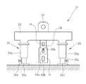
도면을 참조하면, 수평의 크레인빔(11)에 패드아이(13)가 설치되어 있고, 상기 패드아이(13)에, 종래의 패드아이 로드 테스트장치가 적용되어 있음을 알 수 있다.Referring to the drawings, it can be seen that the
상기 패드아이 로드 테스트장치는, 로프(15)와 상부후크(17a)를 통해 상기 패드아이(13)에 매달리는 체인블록(17)과, 상기 체인블록(17)에 체인을 통해 연결되는 하부후크(17b)와, 상기 하부후크(17b)에 매달리는 로드셀(19)과, 상기 로드셀(19)에 접속되며 로스셀(19)이 측정한 데이터를 받아 작업자에게 보여주는 디스플레이수단을 포함한다. The pad eye rod test apparatus includes a
상기 로드셀(19)은 일반적인 로드셀로서, 외부로부터 인가된 인장력에 의해 미세하게 변형될 때의 변형량을 전기신호로 검출한 후 이를 디지털신호로 바꿔 상기 수치화 하는 무게 측정소자이다.The
상기 로드셀(19)은 하부후크(17b)에 매달린 상태로 고정수단을 통해 지면에도 연결되어 있다. The
따라서 도시한 바와같이 작업자가 체인을 화살표 a 방향으로 당기면 상기 하부후크(17b)가 상부로 당겨지며 상기 로드셀(19)에 인장력을 가한다. 상기 로드셀(19)에 가해진 인장력은 로드셀(19)에 접속되어 있는 디스플레이수단(21)을 통해 외부로 디스플레이된다. 상기 로드셀(19)에 가해진 인장력이 패드아이(13)에 인가되는 무게와 같은 값임은 물론이다. 따라서 작업자는 상기 디스플레이수단(21)에 나타난 수치를 기초로 현재 패드아이(13)가 정상적인 상태인지 여부를 판단할 수 있는 것이다.Therefore, as shown in the figure, when the operator pulls the chain in the direction of arrow a, the
그런데 상기한 종래의 패드아이 로드 테스트장치는, 일단 설치하기가 번거롭다는 단점이 있다. 즉 패드아이 로드 테스트장치를 설치하기 위해서는, 로프(15)를 이용하여, 상하부후크(17a,17b)가 구비되어 있는 체인블록(17)을 패드아이(13)에 매달아야 함은 물론, 상기 로드셀(19)을 지면에도 고정시켜야 하는 등의 불편이 있는 것이다.However, the conventional pad eye load test apparatus has a disadvantage in that it is cumbersome to install once. In other words, in order to install the pad eye load test apparatus, the
또한 상기한 종래의 로드 테스트장치는, 그 구조상, 테스트 가능 캐피시티가 얼마 되지 않는다는 문제점도 있다. 이를 테면 로드테스트 중 상기 로프(15)가 절단되기 쉬어 대형 패드아이의 로드테스트는 제대로 할 수 없는 것이다. 상기 로프(15)가 갑자기 절단되면 체인블록(17)의 아래에 있는 작업자가 부상을 입거나 경우에 따라 사망할 수 도 있다.In addition, the conventional load test apparatus described above also has a problem that the testable capacity is very low in terms of its structure. For example, the
본 발명은 상기 문제점을 해소하고자 창출한 것으로서, 그 구조가 간단하고 설치가 간편함은 물론 테스트 가능 캐피시티가 매우 크므로 대형 크레인의 패드아이도 간단히 검사할 수 있는 패드아이 로드 테스트장치를 제공함에 목적이 있다.The present invention has been made to solve the above problems, the structure is simple and easy to install, as well as the testable capacity is very large to provide a pad eye rod test apparatus that can easily inspect the pad eye of a large crane There is this.
상기 목적을 달성하기 위한 본 발명의 패드아이 로드 테스트장치는, 패드아이의 주변에 배치되며 외부로 동력을 제공하는 동력발생부와; 상기 패드아이에 결합하는 인장플레이트와; 상기 인장플레이트와 동력발생부를 연결하며 동력발생부의 동력을 인장플레이트로 전달하여 인장플레이트가 패드아이를 인장하게 하는 프레임과; 상기 패드아이에 가해진 인장력을 측정하여 외부의 디스플레이수단으로 보내는 측정부를 포함하는 것을 특징으로 한다.The pad eye rod test apparatus of the present invention for achieving the above object is disposed around the pad eye and the power generator for providing power to the outside; A tension plate coupled to the pad eye; A frame connecting the tension plate and the power generation unit to transfer the power of the power generation unit to the tension plate so that the tension plate tensions the pad eye; It characterized in that it comprises a measuring unit for measuring the tensile force applied to the pad eye sent to the external display means.
또한, 상기 동력발생부는 상기 패드아이를 중심에 두고 상호 나란하게 배치된 유압액츄에이터인 것을 특징으로 한다.In addition, the power generating unit is characterized in that the hydraulic actuators are arranged side by side with the pad eye at the center.
또한, 상기 패드아이는 수평의 크레인빔에 구비된 것이며, 상기 유압액츄에이터는 상기 크레인빔에 지지된 상태로 구동하여, 상기 인장플에이트를 크레인빔의 수직방향으로 인장하는 것을 특징으로 한다.In addition, the pad eye is provided in a horizontal crane beam, the hydraulic actuator is driven in a state supported by the crane beam, it characterized in that the tension plate is tensioned in the vertical direction of the crane beam.
또한, 상기 인장플레이트와 패드아이의 사이에는, 인장플레이트와 패드아이를 연결하는 연결플레이트가 착탈 가능하게 구비되는 것을 특징으로 한다.In addition, between the tension plate and the pad eye, characterized in that the connection plate for connecting the tension plate and the pad eye is provided detachably.
아울러, 상기 프레임에는, 상기 테스트장치를 들어올릴 수 있는 인상수단이 끼워지는 구멍이 형성된 걸이구가 더 구비된 것을 특징으로 한다.In addition, the frame is characterized in that the hook is further provided with a hole formed in which the pulling means for lifting the test device is fitted.
또한, 상기 측정부는 로드셀(load cell)며, 상기 로드셀은 상기 인장플레이트에 고정된 것을 특징으로 한다.In addition, the measurement unit is a load cell (load cell), characterized in that the load cell is fixed to the tension plate.
상기와 같이 이루어지는 본 발명의 패드아이 로드 테스트장치는, 그 구조가 간단하고 설치가 간편함은 물론 테스트 가능 캐피시티가 매우 크므로 대형 크레인의 패드아이도 간단히 검사할 수 있다.Pad eye rod test apparatus of the present invention made as described above, because the structure is simple and easy to install, as well as the testable capacity is very large, it is possible to simply inspect the pad eye of a large crane.
도 1은 종래 패드아이 로드 테스트 장치의 문제점을 설명하기 위하여 도시한 도면이다.
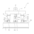
도 2는 본 발명의 일 실시예에 따른 패드아이 로드 테스트 장치의 구성을 나타내 보인 정면도이다.
도 3은 상기 도 2에 도시한 패드아이 로드 테스트 장치의 작동을 설명하기 위하여 도시한 도면이다.
도 4는 상기 도 3에 도시한 패드아이의 측단면도이다.1 is a view illustrating a problem of a conventional pad eye load test apparatus.
Figure 2 is a front view showing the configuration of the pad eye load test apparatus according to an embodiment of the present invention.
FIG. 3 is a diagram illustrating an operation of the pad eye load test apparatus shown in FIG. 2.
4 is a side cross-sectional view of the pad eye shown in FIG. 3.
이하, 본 발명에 따른 하나의 실시예를 첨부된 도면을 참조하여 보다 상세히 설명하기로 한다.Hereinafter, one embodiment according to the present invention will be described in detail with reference to the accompanying drawings.
도 2는 본 발명의 일 실시예에 따른 패드아이 로드 테스트 장치(31)의 구성을 나타내 보인 정면도이다. 도 2에 도시한 로드 테스트 장치(31)는 지면에 일으켜 세운 상태의 모습이다.2 is a front view showing the configuration of the pad eye
도시한 바와같이, 본 실시예에 따른 패드아이 로드 테스트 장치(31)는, 테스트 할 패드아이(13)의 양측부에 수직으로 배치되는 유압액츄에이터(35)와, 상기 유압액츄에이터(35)의 상단부를 연결하는 프레임(33)과, 상기 프레임(33)의 상부에 구비되며 관통구멍이 형성되어 있는 걸이구(37)를 포함한다.As shown, the pad eye
또한 상기 프레임(33)의 중앙 하부에는 인장플레이트(39)가 일체로 구비되어 있고, 상기 인장플레이트(39)에는 연결플레이트(43)가 링크되어 있다.In addition, a
특히 상기 로드 테스트 장치(31)는, 도 3에 도시한 바와같이, 크레인빔(11)을 지면에 내려 패드아이(13)가 위로 향하게 한 상태로, 크레인빔(11)에 올려 사용되는 것이다. 이를 위해 상기 유압액츄에이터(35)의 하단부에는 지지판(35e)이 고정되어 있다. 상기 지지판(35e)은 일정두께의 사각 철판으로서, 액츄에이터(35)가 한쪽으로 넘어가지 않도록 받친다. In particular, as shown in FIG. 3, the
먼저, 상기 유압액츄에이터(35)는 실린더(35a)와 피스톤(35b)으로 구성된 것으로서, 상기 지지판(35e)의 상부에 고정되어 있다. 상기 유압액츄에이터(35)는 유압라인(35d)을 통해 외부로부터 제공된 유압에 의해 동작하여, 상기 프레임(33)을 승강시키는 역할을 한다. 도면부호 35c는 외부의 유압라인(35d)이 연결되는 커넥터이다. First, the
상기 패드아이(13)를 사이에 두고 반대편에 배치되는 유압액츄에이터(35)는 동일한 사이즈 및 용량의 것을 사용한다. 이는 상기 프레임(33)을 수평을 유지한 상태로 승강시키기 위한 것이다. 상기 유압액츄에이터(35)의 사이즈가 다를 경우 프레임(33)이 기울어져 정확한 로드테스트가 불가능해진다.The
상기 프레임(33)은 유압액츄에이터(35)의 상단부에 결합하며 패드아이(13)의 상부를 가로지르는 가로대로서, 액츄에이터(35)의 작동에 의해 승강 운동한다. 상기 프레임(33)은 외력에 의해 하부로 쳐지지 않도록 매우 강한 강성을 가져야 함은 물론이다.The
아울러 상기 프레임(33)의 상부에 고정되어 있는 걸이구(37)는, 가령 크레인(미도시)의 후크가 끼워질 수 있는 관통구멍을 갖는 철판이다. 참고로, 본 실시예의 로드 테스트장치(31)는 그 기본 중량이 무거우므로, 인력으로 운반하기가 힘들기 때문에 크레인 등의 장비를 통해 운반한다.In addition, the
한편, 상기 프레임(33)의 중앙 하부에 구비되어 있는 인장플레이트(39)는, 프레임(33)에 일체를 이루며 하부로 연장된 플레이트 형태의 부재로서, 그 외측면에 로드셀(41)을 갖는다. 상기 로드셀(41)은, 패드아이 로드 테스트시, 인장플레이트(39)와 함께 미세 변형하여 가해진 무게를 출력한다. 상기 로드셀(41)은 일반적인 것을 사용해도 무방하다.On the other hand, the
또한 상기 인장플레이트(39)의 양측면에는 걸림핀(39a)이 구비되어 있다. 상기 걸림핀(39a)은 인장플레이트(39)를 두께 방향으로 통과하여, 그 양단부가 인장플레이트(39)로부터 돌출된 것으로서, 연결플레이트(43)의 상부장공(43a)에 끼워진다. 이와 같이 걸림핀(39a)이 상부장공(43a)에 삽입되어 있으므로, 연결플레이트(43)는 상부장공(43a)이 허용하는 범위내에서 상하로 움직임이 가능하다.In addition, both sides of the
상기 인장플레이트(39)에 링크되는 연결플레이트(43)는, 도 4에 도시한 바와같이, 두 장의 철판이 평행하게 쌍을 이룬 것이며, 상기 인장플레이트(39)를 그 사이에 유지한다.As shown in FIG. 4, the connecting
상기 인장플레이트(39)에는 상부장공(43a)과 하부장공(43b)이 형성되어 있다. 상기 상부장공(43a)에는 걸림핀(39a)이 끼워지고, 하부장공(43b)에는 볼트(도 4의 45)가 통과한다. 상기 볼트(45)는 연결플레이트(43)에 패드아이(13)를 연결시키기 위한 것으로서, 일측 연결플레이트(43)의 하부장공(43b)과 패드아이(13)와 타측 연결플레이트(43)의 하부장공(43b)을 통과한 후 너트(47)와 나사 결합함으로써, 패드아이(13)에 대해 로드 테스트 장치(31)를 링크시킨다.The
상기 인장플레이트(39)의 두께와, 상부장공(43a)과 하부장공(43b)의 사이즈는 로드 테스트장치의 용량에 따라 당연히 달라진다. The thickness of the
도 3은 상기 도 2에 도시한 패드아이 로드 테스트 장치(31)의 작동을 설명하기 위하여 도시한 도면이고, 도 4는 상기 도 3에 도시한 패드아이의 측단면도이다.3 is a view for explaining the operation of the pad eye
도면을 참조하면, 상기 패드아이(13)가 상향 배치되도록 놓여진 크레인빔(11) 위에 본 실시예의 로드 테스트 장치(31)가 올라가 있음을 알 수 있다. 상기 로드 테스트 장치(31)는 지지판(35e)의 작용에 의해 한쪽으로 넘어가지 않고 안정적으로 기립된 상태를 유지한다.Referring to the drawings, it can be seen that the
여하튼, 상기 패드아이(13)는, 볼트(45)와 너트(47)를 통해 상기 연결플레이트(43)에 링크되어 있다. 또한 상기 연결플레이트(43)는 자중에 의해 하부로 쳐져 있는 상태로 대기한다.In any case, the
이 상태에서, 패드아이(13)의 로드테스트를 하려면 상기 유압액츄에이터(35)를 동작시킨다. 상기 유압액츄에이터(35)에 유압을 제공하면, 상기 실린더(35a)가 상승하며 프레임(33)이 올라간다. In this state, the
상기 액츄에이터(35)의 작동에 의해 프레임(33)이 상향 이동함에 따라, 상부장공(43a)에 끼워져 있는 걸림핀(39a)과 하부장공(43b)을 관통하고 있는 볼트(45)가 장공의 길이만큼 상승하고, 마침내 장공의 상단부에 도달한 순간 패드아이(13)가 상부로 인장되기 시작한다.As the
이와 같이 패드아이(13)가 연결플레이트(43)와 인장플레이트(39)에 의해 상향 인장되는 동안, 상기 로드셀(41)은 인장플레이트(39)의 미세한 변형량을 감지하고 그 내용을 외부의 디스플레이수단으로 보낸다. As described above, while the
상기 디스플레이수단은 공지의 것으로서, 로드셀(41)로부터 전달받은 정보를 기초로 현재 패드아이(13)에 가해지고 있는 무게를 수치로 표시하여 작업자가 적절한 판단을 하도록 한다.The display means is known, and displays the weight currently being applied to the
상기 과정을 통한 테스트가 완료되었다면, 상기 볼트(45) 및 너트(47)를 해체한 후, 크레인의 후크(미도시)를 걸이구(37)에 끼워 테스트장치(31)를 내려 놓는다.If the test through the above process is completed, the
이상, 본 발명을 구체적인 실시예를 통하여 상세하게 설명하였으나, 본 발명은 상기 실시예에 한정하지 않고, 본 발명의 기술적 사상의 범위내에서 통상의 지식을 가진 자에 의하여 여러 가지 변형이 가능하다.While the present invention has been particularly shown and described with reference to exemplary embodiments thereof, it is to be understood that the invention is not limited to the disclosed exemplary embodiments, but, on the contrary, is intended to cover various modifications and equivalent arrangements included within the spirit and scope of the appended claims.
11:크레인빔 13:패드아이
15:로프 17:체인블록
17a:상부후크 17b:하부후크
19:로드셀 21:디스플레이수단
31:로드테스트장치 33:프레임
35:유압액츄에이터 35a:실린더
35b:피스톤 35c:커넥터
35d:유압라인 35e:지지판
37:걸이구 39:인장플레이트
39a:걸림핀 41:로드셀
43:연결플레이트 43a:상부장공
43b:하부장공 45:볼트
47:너트11: Crane Beam 13: Pad Eye
15: Rope 17: Chain Block
17a:
19: load cell 21: display means
31: load test device 33: frame
35:
35b:
35d:
37: Hook mouth 39: Tension plate
39a: latching pin 41: load cell
43:
43b: lower part worker 45: bolt
It is a nut
Claims (7)
상기 패드아이에 결합하는 인장플레이트와;
상기 인장플레이트와 동력발생부를 연결하며 동력발생부의 동력을 인장플레이트로 전달하여 인장플레이트가 패드아이를 인장하게 하는 프레임과;
상기 패드아이에 가해진 인장력을 측정하여 외부의 디스플레이수단으로 보내는 측정부를 포함하는 것을 특징으로 하는 패드아이 로드 테스트장치.A power generation unit disposed around the pad eye and providing power to the outside;
A tension plate coupled to the pad eye;
A frame connecting the tension plate and the power generation unit to transfer the power of the power generation unit to the tension plate so that the tension plate tensions the pad eye;
Pad eye rod test apparatus comprising a measuring unit for measuring the tensile force applied to the pad eye to send to the external display means.
상기 동력발생부는 상기 패드아이를 중심에 두고 상호 나란하게 배치된 유압액츄에이터인 것을 특징으로 하는 패드아이 로드 테스트장치.The method of claim 1,
The power generating unit is a pad eye rod test apparatus, characterized in that the hydraulic actuators are arranged side by side with the pad eye at the center.
상기 패드아이는 수평의 크레인빔에 구비된 것이며, 상기 유압액츄에이터는 상기 크레인빔에 지지된 상태로 구동하여, 상기 인장플레이트를 크레인빔의 수직방향으로 인장하는 것을 특징으로 하는 패드아이 로드 테스트장치.The method of claim 2,
The pad eye is provided in a horizontal crane beam, the hydraulic actuator is driven in a state supported by the crane beam, the pad eye rod test apparatus, characterized in that for pulling the tension plate in the vertical direction of the crane beam.
상기 인장플레이트와 패드아이의 사이에는, 인장플레이트와 패드아이를 연결하는 연결플레이트가 착탈 가능하게 구비되는 것을 특징으로 하는 패드아이 로드 테스트장치.The method of claim 2,
Pad eye rod test device, characterized in that between the tension plate and the pad eye, the connection plate for connecting the tension plate and the pad eye is provided detachably.
상기 프레임에는, 상기 테스트장치를 들어올릴 수 있는 인상수단이 끼워지는 구멍이 형성된 걸이구가 더 구비된 것을 특징으로 하는 패드아이 로드 테스트장치.The method of claim 1,
The frame, rod eye rod test apparatus, characterized in that the hook hole is further provided with a hole for fitting the lifting means for lifting the test device.
상기 측정부는 로드셀(load cell)인 것을 특징으로 하는 패드아이 로드 테스트장치.The method of claim 1,
The test unit pad eye load test apparatus, characterized in that the load cell (load cell).
상기 로드셀은 상기 인장플레이트에 고정된 것을 특징으로 하는 패드아이 로드 테스트장치.The method according to claim 6,
Pad eye load test apparatus, characterized in that the load cell is fixed to the tension plate.
Priority Applications (1)
| Application Number | Priority Date | Filing Date | Title |
|---|---|---|---|
| KR1020110143855A KR20130075478A (en) | 2011-12-27 | 2011-12-27 | Pad eye load test device |
Applications Claiming Priority (1)
| Application Number | Priority Date | Filing Date | Title |
|---|---|---|---|
| KR1020110143855A KR20130075478A (en) | 2011-12-27 | 2011-12-27 | Pad eye load test device |
Publications (1)
| Publication Number | Publication Date |
|---|---|
| KR20130075478A true KR20130075478A (en) | 2013-07-05 |
Family
ID=48989359
Family Applications (1)
| Application Number | Title | Priority Date | Filing Date |
|---|---|---|---|
| KR1020110143855A KR20130075478A (en) | 2011-12-27 | 2011-12-27 | Pad eye load test device |
Country Status (1)
| Country | Link |
|---|---|
| KR (1) | KR20130075478A (en) |
Cited By (2)
| Publication number | Priority date | Publication date | Assignee | Title |
|---|---|---|---|---|
| US20140360283A1 (en) * | 2011-11-24 | 2014-12-11 | Proserv Offshore Pty Ltd | Padeye tester |
| CN109470572A (en) * | 2018-12-07 | 2019-03-15 | 南京航空航天大学 | A kind of novel test device suitable for bending plate stretching |
-
2011
- 2011-12-27 KR KR1020110143855A patent/KR20130075478A/en not_active Application Discontinuation
Cited By (2)
| Publication number | Priority date | Publication date | Assignee | Title |
|---|---|---|---|---|
| US20140360283A1 (en) * | 2011-11-24 | 2014-12-11 | Proserv Offshore Pty Ltd | Padeye tester |
| CN109470572A (en) * | 2018-12-07 | 2019-03-15 | 南京航空航天大学 | A kind of novel test device suitable for bending plate stretching |
Similar Documents
| Publication | Publication Date | Title |
|---|---|---|
| KR200469925Y1 (en) | Lifting lug load test apparatus | |
| CN104034596B (en) | A kind of lever crouches pull-type concrete creep and elasticity modulus test device | |
| KR20120114706A (en) | Load test apparatus | |
| RU2005140099A (en) | TEST LEVER | |
| CN103771219B (en) | The hanger tension testing fixture of elevator and hanger tension inspection method | |
| KR20130075478A (en) | Pad eye load test device | |
| CN207502301U (en) | A kind of mechanical tensile testing machine | |
| CN104236779A (en) | Rope tensile force testing device | |
| KR100960223B1 (en) | Apparatus for pure shear strength test of test specimen | |
| CN202471519U (en) | Electronic display-type pail tensile testing machine | |
| CN103115762B (en) | Tension tester | |
| CN109142040B (en) | Remote control's sudden load test device | |
| CN108918115A (en) | Bridge crane no-load load testing machine and method | |
| KR20140143250A (en) | Load test apparatus for overhead lug and load test apparatus of overhead lug using it | |
| KR101104268B1 (en) | Method and apparatus for testing of lug load using hydraulic and pneumatic | |
| CN208471398U (en) | A kind of device for bridge crane no-load load test | |
| CN204988900U (en) | Device is examined to pulling force point | |
| CN203587438U (en) | Steel wire rope tension tester | |
| KR20190018971A (en) | Apparatus for testing by vibration | |
| CN207600851U (en) | A kind of 90 degree of layback tension test fixtures | |
| CN213544036U (en) | Small-size lifting device pulling force detection test device | |
| CN211121934U (en) | Portable lifter trailing arm rotation angle locking device detection device | |
| CN105588764B (en) | The method and device of simplicity detection structural steel intensity | |
| CN214879371U (en) | Strength tester for hoisting traction rope of elevator steel structure hoistway | |
| CN103983465A (en) | Device for loading self-balancing gravity load |
Legal Events
| Date | Code | Title | Description |
|---|---|---|---|
| WITN | Application deemed withdrawn, e.g. because no request for examination was filed or no examination fee was paid |