KR20130064730A - Composite layer - Google Patents
Composite layer Download PDFInfo
- Publication number
- KR20130064730A KR20130064730A KR1020127027301A KR20127027301A KR20130064730A KR 20130064730 A KR20130064730 A KR 20130064730A KR 1020127027301 A KR1020127027301 A KR 1020127027301A KR 20127027301 A KR20127027301 A KR 20127027301A KR 20130064730 A KR20130064730 A KR 20130064730A
- Authority
- KR
- South Korea
- Prior art keywords
- composite layer
- shims
- cavity
- die
- shim
- Prior art date
Links
- 239000002131 composite material Substances 0.000 title claims abstract description 79
- 239000000463 material Substances 0.000 claims abstract description 89
- 239000011159 matrix material Substances 0.000 claims abstract description 4
- 230000001070 adhesive effect Effects 0.000 claims description 58
- 239000000853 adhesive Substances 0.000 claims description 53
- 238000000034 method Methods 0.000 claims description 16
- 239000003795 chemical substances by application Substances 0.000 claims description 7
- 239000010410 layer Substances 0.000 description 62
- 238000001125 extrusion Methods 0.000 description 33
- 229920000642 polymer Polymers 0.000 description 27
- -1 polytetrafluoroethylene Polymers 0.000 description 20
- 229920001577 copolymer Polymers 0.000 description 13
- 239000004698 Polyethylene Substances 0.000 description 12
- 125000006850 spacer group Chemical group 0.000 description 12
- 239000000178 monomer Substances 0.000 description 10
- 229920000573 polyethylene Polymers 0.000 description 10
- 239000004820 Pressure-sensitive adhesive Substances 0.000 description 9
- 239000002861 polymer material Substances 0.000 description 9
- 239000003086 colorant Substances 0.000 description 8
- SMZOUWXMTYCWNB-UHFFFAOYSA-N 2-(2-methoxy-5-methylphenyl)ethanamine Chemical compound COC1=CC=C(C)C=C1CCN SMZOUWXMTYCWNB-UHFFFAOYSA-N 0.000 description 7
- NIXOWILDQLNWCW-UHFFFAOYSA-N 2-Propenoic acid Natural products OC(=O)C=C NIXOWILDQLNWCW-UHFFFAOYSA-N 0.000 description 7
- 239000004743 Polypropylene Substances 0.000 description 7
- 229920000139 polyethylene terephthalate Polymers 0.000 description 7
- 239000000203 mixture Substances 0.000 description 6
- 239000005020 polyethylene terephthalate Substances 0.000 description 6
- 210000003491 skin Anatomy 0.000 description 6
- 229910001220 stainless steel Inorganic materials 0.000 description 6
- 239000010935 stainless steel Substances 0.000 description 6
- 239000012530 fluid Substances 0.000 description 5
- 238000004519 manufacturing process Methods 0.000 description 5
- 229920001155 polypropylene Polymers 0.000 description 5
- GOXQRTZXKQZDDN-UHFFFAOYSA-N 2-Ethylhexyl acrylate Chemical compound CCCCC(CC)COC(=O)C=C GOXQRTZXKQZDDN-UHFFFAOYSA-N 0.000 description 4
- PPBRXRYQALVLMV-UHFFFAOYSA-N Styrene Chemical compound C=CC1=CC=CC=C1 PPBRXRYQALVLMV-UHFFFAOYSA-N 0.000 description 4
- 230000008901 benefit Effects 0.000 description 4
- 239000011248 coating agent Substances 0.000 description 4
- 238000000576 coating method Methods 0.000 description 4
- 229920001971 elastomer Polymers 0.000 description 4
- 239000008188 pellet Substances 0.000 description 4
- 229920000728 polyester Polymers 0.000 description 4
- 230000008569 process Effects 0.000 description 4
- 230000003287 optical effect Effects 0.000 description 3
- 229920001296 polysiloxane Polymers 0.000 description 3
- 239000004814 polyurethane Substances 0.000 description 3
- 229920002635 polyurethane Polymers 0.000 description 3
- 239000000126 substance Substances 0.000 description 3
- DXPPIEDUBFUSEZ-UHFFFAOYSA-N 6-methylheptyl prop-2-enoate Chemical compound CC(C)CCCCCOC(=O)C=C DXPPIEDUBFUSEZ-UHFFFAOYSA-N 0.000 description 2
- RYGMFSIKBFXOCR-UHFFFAOYSA-N Copper Chemical compound [Cu] RYGMFSIKBFXOCR-UHFFFAOYSA-N 0.000 description 2
- 239000004793 Polystyrene Substances 0.000 description 2
- VYPSYNLAJGMNEJ-UHFFFAOYSA-N Silicium dioxide Chemical compound O=[Si]=O VYPSYNLAJGMNEJ-UHFFFAOYSA-N 0.000 description 2
- 239000002390 adhesive tape Substances 0.000 description 2
- 239000012141 concentrate Substances 0.000 description 2
- 238000007796 conventional method Methods 0.000 description 2
- 229910052802 copper Inorganic materials 0.000 description 2
- 239000010949 copper Substances 0.000 description 2
- 239000000806 elastomer Substances 0.000 description 2
- 238000010894 electron beam technology Methods 0.000 description 2
- FJKIXWOMBXYWOQ-UHFFFAOYSA-N ethenoxyethane Chemical compound CCOC=C FJKIXWOMBXYWOQ-UHFFFAOYSA-N 0.000 description 2
- 230000009969 flowable effect Effects 0.000 description 2
- 238000010438 heat treatment Methods 0.000 description 2
- 238000005259 measurement Methods 0.000 description 2
- 239000002184 metal Substances 0.000 description 2
- 229910052751 metal Inorganic materials 0.000 description 2
- 229920000098 polyolefin Polymers 0.000 description 2
- 229920006124 polyolefin elastomer Polymers 0.000 description 2
- 229920002223 polystyrene Polymers 0.000 description 2
- 229920001343 polytetrafluoroethylene Polymers 0.000 description 2
- 239000004810 polytetrafluoroethylene Substances 0.000 description 2
- 239000004800 polyvinyl chloride Substances 0.000 description 2
- 229920000915 polyvinyl chloride Polymers 0.000 description 2
- 239000005060 rubber Substances 0.000 description 2
- 239000007787 solid Substances 0.000 description 2
- 241000282472 Canis lupus familiaris Species 0.000 description 1
- 241000723418 Carya Species 0.000 description 1
- 229920008347 Cellulose acetate propionate Polymers 0.000 description 1
- 229920002284 Cellulose triacetate Polymers 0.000 description 1
- VGGSQFUCUMXWEO-UHFFFAOYSA-N Ethene Chemical compound C=C VGGSQFUCUMXWEO-UHFFFAOYSA-N 0.000 description 1
- 239000005977 Ethylene Substances 0.000 description 1
- 244000043261 Hevea brasiliensis Species 0.000 description 1
- 239000004677 Nylon Substances 0.000 description 1
- 241001330988 Palmyra Species 0.000 description 1
- 239000004952 Polyamide Substances 0.000 description 1
- 239000005062 Polybutadiene Substances 0.000 description 1
- 239000004695 Polyether sulfone Substances 0.000 description 1
- 239000004642 Polyimide Substances 0.000 description 1
- 229920002396 Polyurea Polymers 0.000 description 1
- BZHJMEDXRYGGRV-UHFFFAOYSA-N Vinyl chloride Chemical compound ClC=C BZHJMEDXRYGGRV-UHFFFAOYSA-N 0.000 description 1
- NNLVGZFZQQXQNW-ADJNRHBOSA-N [(2r,3r,4s,5r,6s)-4,5-diacetyloxy-3-[(2s,3r,4s,5r,6r)-3,4,5-triacetyloxy-6-(acetyloxymethyl)oxan-2-yl]oxy-6-[(2r,3r,4s,5r,6s)-4,5,6-triacetyloxy-2-(acetyloxymethyl)oxan-3-yl]oxyoxan-2-yl]methyl acetate Chemical compound O([C@@H]1O[C@@H]([C@H]([C@H](OC(C)=O)[C@H]1OC(C)=O)O[C@H]1[C@@H]([C@@H](OC(C)=O)[C@H](OC(C)=O)[C@@H](COC(C)=O)O1)OC(C)=O)COC(=O)C)[C@@H]1[C@@H](COC(C)=O)O[C@@H](OC(C)=O)[C@H](OC(C)=O)[C@H]1OC(C)=O NNLVGZFZQQXQNW-ADJNRHBOSA-N 0.000 description 1
- 239000012080 ambient air Substances 0.000 description 1
- 229920001400 block copolymer Polymers 0.000 description 1
- 229920005549 butyl rubber Polymers 0.000 description 1
- 229920006217 cellulose acetate butyrate Polymers 0.000 description 1
- 230000008859 change Effects 0.000 description 1
- 230000006835 compression Effects 0.000 description 1
- 238000007906 compression Methods 0.000 description 1
- 238000010276 construction Methods 0.000 description 1
- 238000001816 cooling Methods 0.000 description 1
- 230000001351 cycling effect Effects 0.000 description 1
- 239000000975 dye Substances 0.000 description 1
- 238000005516 engineering process Methods 0.000 description 1
- 238000004299 exfoliation Methods 0.000 description 1
- 230000001747 exhibiting effect Effects 0.000 description 1
- 239000004744 fabric Substances 0.000 description 1
- 239000000945 filler Substances 0.000 description 1
- LNMQRPPRQDGUDR-UHFFFAOYSA-N hexyl prop-2-enoate Chemical compound CCCCCCOC(=O)C=C LNMQRPPRQDGUDR-UHFFFAOYSA-N 0.000 description 1
- 230000002209 hydrophobic effect Effects 0.000 description 1
- 208000014674 injury Diseases 0.000 description 1
- 238000010030 laminating Methods 0.000 description 1
- 238000003754 machining Methods 0.000 description 1
- 238000012986 modification Methods 0.000 description 1
- 230000004048 modification Effects 0.000 description 1
- KYTZHLUVELPASH-UHFFFAOYSA-N naphthalene-1,2-dicarboxylic acid Chemical compound C1=CC=CC2=C(C(O)=O)C(C(=O)O)=CC=C21 KYTZHLUVELPASH-UHFFFAOYSA-N 0.000 description 1
- 229920003052 natural elastomer Polymers 0.000 description 1
- 229920001194 natural rubber Polymers 0.000 description 1
- 229920001778 nylon Polymers 0.000 description 1
- 239000002245 particle Substances 0.000 description 1
- 239000000049 pigment Substances 0.000 description 1
- 229920003023 plastic Polymers 0.000 description 1
- 239000004033 plastic Substances 0.000 description 1
- 229920001084 poly(chloroprene) Polymers 0.000 description 1
- 229920003207 poly(ethylene-2,6-naphthalate) Polymers 0.000 description 1
- 229920001200 poly(ethylene-vinyl acetate) Polymers 0.000 description 1
- 229920003229 poly(methyl methacrylate) Polymers 0.000 description 1
- 229920002647 polyamide Polymers 0.000 description 1
- 229920002857 polybutadiene Polymers 0.000 description 1
- 239000004417 polycarbonate Substances 0.000 description 1
- 229920000515 polycarbonate Polymers 0.000 description 1
- 229920006393 polyether sulfone Polymers 0.000 description 1
- 239000011112 polyethylene naphthalate Substances 0.000 description 1
- 229920001721 polyimide Polymers 0.000 description 1
- 239000004926 polymethyl methacrylate Substances 0.000 description 1
- 229920003225 polyurethane elastomer Polymers 0.000 description 1
- SCUZVMOVTVSBLE-UHFFFAOYSA-N prop-2-enenitrile;styrene Chemical compound C=CC#N.C=CC1=CC=CC=C1 SCUZVMOVTVSBLE-UHFFFAOYSA-N 0.000 description 1
- 238000010791 quenching Methods 0.000 description 1
- 230000000171 quenching effect Effects 0.000 description 1
- 230000005855 radiation Effects 0.000 description 1
- 230000003014 reinforcing effect Effects 0.000 description 1
- 238000007789 sealing Methods 0.000 description 1
- 239000000377 silicon dioxide Substances 0.000 description 1
- 239000002356 single layer Substances 0.000 description 1
- 210000004927 skin cell Anatomy 0.000 description 1
- 229920000638 styrene acrylonitrile Polymers 0.000 description 1
- 229920006132 styrene block copolymer Polymers 0.000 description 1
- 239000000758 substrate Substances 0.000 description 1
- 238000012546 transfer Methods 0.000 description 1
- 238000002834 transmittance Methods 0.000 description 1
- 230000008733 trauma Effects 0.000 description 1
- 239000010981 turquoise Substances 0.000 description 1
- 238000012800 visualization Methods 0.000 description 1
- 229940089401 xylon Drugs 0.000 description 1
Images


Classifications
-
- B—PERFORMING OPERATIONS; TRANSPORTING
- B29—WORKING OF PLASTICS; WORKING OF SUBSTANCES IN A PLASTIC STATE IN GENERAL
- B29C—SHAPING OR JOINING OF PLASTICS; SHAPING OF MATERIAL IN A PLASTIC STATE, NOT OTHERWISE PROVIDED FOR; AFTER-TREATMENT OF THE SHAPED PRODUCTS, e.g. REPAIRING
- B29C48/00—Extrusion moulding, i.e. expressing the moulding material through a die or nozzle which imparts the desired form; Apparatus therefor
- B29C48/16—Articles comprising two or more components, e.g. co-extruded layers
- B29C48/18—Articles comprising two or more components, e.g. co-extruded layers the components being layers
- B29C48/21—Articles comprising two or more components, e.g. co-extruded layers the components being layers the layers being joined at their surfaces
-
- B—PERFORMING OPERATIONS; TRANSPORTING
- B29—WORKING OF PLASTICS; WORKING OF SUBSTANCES IN A PLASTIC STATE IN GENERAL
- B29C—SHAPING OR JOINING OF PLASTICS; SHAPING OF MATERIAL IN A PLASTIC STATE, NOT OTHERWISE PROVIDED FOR; AFTER-TREATMENT OF THE SHAPED PRODUCTS, e.g. REPAIRING
- B29C48/00—Extrusion moulding, i.e. expressing the moulding material through a die or nozzle which imparts the desired form; Apparatus therefor
- B29C48/03—Extrusion moulding, i.e. expressing the moulding material through a die or nozzle which imparts the desired form; Apparatus therefor characterised by the shape of the extruded material at extrusion
- B29C48/07—Flat, e.g. panels
- B29C48/08—Flat, e.g. panels flexible, e.g. films
-
- B—PERFORMING OPERATIONS; TRANSPORTING
- B29—WORKING OF PLASTICS; WORKING OF SUBSTANCES IN A PLASTIC STATE IN GENERAL
- B29C—SHAPING OR JOINING OF PLASTICS; SHAPING OF MATERIAL IN A PLASTIC STATE, NOT OTHERWISE PROVIDED FOR; AFTER-TREATMENT OF THE SHAPED PRODUCTS, e.g. REPAIRING
- B29C48/00—Extrusion moulding, i.e. expressing the moulding material through a die or nozzle which imparts the desired form; Apparatus therefor
- B29C48/16—Articles comprising two or more components, e.g. co-extruded layers
- B29C48/18—Articles comprising two or more components, e.g. co-extruded layers the components being layers
- B29C48/19—Articles comprising two or more components, e.g. co-extruded layers the components being layers the layers being joined at their edges
-
- B—PERFORMING OPERATIONS; TRANSPORTING
- B29—WORKING OF PLASTICS; WORKING OF SUBSTANCES IN A PLASTIC STATE IN GENERAL
- B29C—SHAPING OR JOINING OF PLASTICS; SHAPING OF MATERIAL IN A PLASTIC STATE, NOT OTHERWISE PROVIDED FOR; AFTER-TREATMENT OF THE SHAPED PRODUCTS, e.g. REPAIRING
- B29C48/00—Extrusion moulding, i.e. expressing the moulding material through a die or nozzle which imparts the desired form; Apparatus therefor
- B29C48/25—Component parts, details or accessories; Auxiliary operations
- B29C48/30—Extrusion nozzles or dies
- B29C48/305—Extrusion nozzles or dies having a wide opening, e.g. for forming sheets
- B29C48/307—Extrusion nozzles or dies having a wide opening, e.g. for forming sheets specially adapted for bringing together components, e.g. melts within the die
-
- B—PERFORMING OPERATIONS; TRANSPORTING
- B29—WORKING OF PLASTICS; WORKING OF SUBSTANCES IN A PLASTIC STATE IN GENERAL
- B29C—SHAPING OR JOINING OF PLASTICS; SHAPING OF MATERIAL IN A PLASTIC STATE, NOT OTHERWISE PROVIDED FOR; AFTER-TREATMENT OF THE SHAPED PRODUCTS, e.g. REPAIRING
- B29C48/00—Extrusion moulding, i.e. expressing the moulding material through a die or nozzle which imparts the desired form; Apparatus therefor
- B29C48/25—Component parts, details or accessories; Auxiliary operations
- B29C48/30—Extrusion nozzles or dies
- B29C48/305—Extrusion nozzles or dies having a wide opening, e.g. for forming sheets
- B29C48/31—Extrusion nozzles or dies having a wide opening, e.g. for forming sheets being adjustable, i.e. having adjustable exit sections
-
- B—PERFORMING OPERATIONS; TRANSPORTING
- B32—LAYERED PRODUCTS
- B32B—LAYERED PRODUCTS, i.e. PRODUCTS BUILT-UP OF STRATA OF FLAT OR NON-FLAT, e.g. CELLULAR OR HONEYCOMB, FORM
- B32B27/00—Layered products comprising a layer of synthetic resin
- B32B27/06—Layered products comprising a layer of synthetic resin as the main or only constituent of a layer, which is next to another layer of the same or of a different material
- B32B27/08—Layered products comprising a layer of synthetic resin as the main or only constituent of a layer, which is next to another layer of the same or of a different material of synthetic resin
-
- B—PERFORMING OPERATIONS; TRANSPORTING
- B32—LAYERED PRODUCTS
- B32B—LAYERED PRODUCTS, i.e. PRODUCTS BUILT-UP OF STRATA OF FLAT OR NON-FLAT, e.g. CELLULAR OR HONEYCOMB, FORM
- B32B27/00—Layered products comprising a layer of synthetic resin
- B32B27/30—Layered products comprising a layer of synthetic resin comprising vinyl (co)polymers; comprising acrylic (co)polymers
- B32B27/308—Layered products comprising a layer of synthetic resin comprising vinyl (co)polymers; comprising acrylic (co)polymers comprising acrylic (co)polymers
-
- B—PERFORMING OPERATIONS; TRANSPORTING
- B32—LAYERED PRODUCTS
- B32B—LAYERED PRODUCTS, i.e. PRODUCTS BUILT-UP OF STRATA OF FLAT OR NON-FLAT, e.g. CELLULAR OR HONEYCOMB, FORM
- B32B27/00—Layered products comprising a layer of synthetic resin
- B32B27/32—Layered products comprising a layer of synthetic resin comprising polyolefins
-
- B—PERFORMING OPERATIONS; TRANSPORTING
- B32—LAYERED PRODUCTS
- B32B—LAYERED PRODUCTS, i.e. PRODUCTS BUILT-UP OF STRATA OF FLAT OR NON-FLAT, e.g. CELLULAR OR HONEYCOMB, FORM
- B32B3/00—Layered products comprising a layer with external or internal discontinuities or unevennesses, or a layer of non-planar form; Layered products having particular features of form
- B32B3/10—Layered products comprising a layer with external or internal discontinuities or unevennesses, or a layer of non-planar form; Layered products having particular features of form characterised by a discontinuous layer, i.e. formed of separate pieces of material
- B32B3/14—Layered products comprising a layer with external or internal discontinuities or unevennesses, or a layer of non-planar form; Layered products having particular features of form characterised by a discontinuous layer, i.e. formed of separate pieces of material characterised by a face layer formed of separate pieces of material which are juxtaposed side-by-side
- B32B3/16—Layered products comprising a layer with external or internal discontinuities or unevennesses, or a layer of non-planar form; Layered products having particular features of form characterised by a discontinuous layer, i.e. formed of separate pieces of material characterised by a face layer formed of separate pieces of material which are juxtaposed side-by-side secured to a flexible backing
-
- C—CHEMISTRY; METALLURGY
- C08—ORGANIC MACROMOLECULAR COMPOUNDS; THEIR PREPARATION OR CHEMICAL WORKING-UP; COMPOSITIONS BASED THEREON
- C08J—WORKING-UP; GENERAL PROCESSES OF COMPOUNDING; AFTER-TREATMENT NOT COVERED BY SUBCLASSES C08B, C08C, C08F, C08G or C08H
- C08J5/00—Manufacture of articles or shaped materials containing macromolecular substances
- C08J5/18—Manufacture of films or sheets
-
- C—CHEMISTRY; METALLURGY
- C09—DYES; PAINTS; POLISHES; NATURAL RESINS; ADHESIVES; COMPOSITIONS NOT OTHERWISE PROVIDED FOR; APPLICATIONS OF MATERIALS NOT OTHERWISE PROVIDED FOR
- C09J—ADHESIVES; NON-MECHANICAL ASPECTS OF ADHESIVE PROCESSES IN GENERAL; ADHESIVE PROCESSES NOT PROVIDED FOR ELSEWHERE; USE OF MATERIALS AS ADHESIVES
- C09J123/00—Adhesives based on homopolymers or copolymers of unsaturated aliphatic hydrocarbons having only one carbon-to-carbon double bond; Adhesives based on derivatives of such polymers
- C09J123/02—Adhesives based on homopolymers or copolymers of unsaturated aliphatic hydrocarbons having only one carbon-to-carbon double bond; Adhesives based on derivatives of such polymers not modified by chemical after-treatment
- C09J123/04—Homopolymers or copolymers of ethene
- C09J123/06—Polyethene
-
- C—CHEMISTRY; METALLURGY
- C09—DYES; PAINTS; POLISHES; NATURAL RESINS; ADHESIVES; COMPOSITIONS NOT OTHERWISE PROVIDED FOR; APPLICATIONS OF MATERIALS NOT OTHERWISE PROVIDED FOR
- C09J—ADHESIVES; NON-MECHANICAL ASPECTS OF ADHESIVE PROCESSES IN GENERAL; ADHESIVE PROCESSES NOT PROVIDED FOR ELSEWHERE; USE OF MATERIALS AS ADHESIVES
- C09J123/00—Adhesives based on homopolymers or copolymers of unsaturated aliphatic hydrocarbons having only one carbon-to-carbon double bond; Adhesives based on derivatives of such polymers
- C09J123/02—Adhesives based on homopolymers or copolymers of unsaturated aliphatic hydrocarbons having only one carbon-to-carbon double bond; Adhesives based on derivatives of such polymers not modified by chemical after-treatment
- C09J123/10—Homopolymers or copolymers of propene
- C09J123/12—Polypropene
-
- C—CHEMISTRY; METALLURGY
- C09—DYES; PAINTS; POLISHES; NATURAL RESINS; ADHESIVES; COMPOSITIONS NOT OTHERWISE PROVIDED FOR; APPLICATIONS OF MATERIALS NOT OTHERWISE PROVIDED FOR
- C09J—ADHESIVES; NON-MECHANICAL ASPECTS OF ADHESIVE PROCESSES IN GENERAL; ADHESIVE PROCESSES NOT PROVIDED FOR ELSEWHERE; USE OF MATERIALS AS ADHESIVES
- C09J133/00—Adhesives based on homopolymers or copolymers of compounds having one or more unsaturated aliphatic radicals, each having only one carbon-to-carbon double bond, and at least one being terminated by only one carboxyl radical, or of salts, anhydrides, esters, amides, imides, or nitriles thereof; Adhesives based on derivatives of such polymers
- C09J133/04—Homopolymers or copolymers of esters
- C09J133/06—Homopolymers or copolymers of esters of esters containing only carbon, hydrogen and oxygen, the oxygen atom being present only as part of the carboxyl radical
- C09J133/08—Homopolymers or copolymers of acrylic acid esters
-
- B—PERFORMING OPERATIONS; TRANSPORTING
- B29—WORKING OF PLASTICS; WORKING OF SUBSTANCES IN A PLASTIC STATE IN GENERAL
- B29K—INDEXING SCHEME ASSOCIATED WITH SUBCLASSES B29B, B29C OR B29D, RELATING TO MOULDING MATERIALS OR TO MATERIALS FOR MOULDS, REINFORCEMENTS, FILLERS OR PREFORMED PARTS, e.g. INSERTS
- B29K2023/00—Use of polyalkenes or derivatives thereof as moulding material
- B29K2023/04—Polymers of ethylene
- B29K2023/06—PE, i.e. polyethylene
-
- B—PERFORMING OPERATIONS; TRANSPORTING
- B29—WORKING OF PLASTICS; WORKING OF SUBSTANCES IN A PLASTIC STATE IN GENERAL
- B29K—INDEXING SCHEME ASSOCIATED WITH SUBCLASSES B29B, B29C OR B29D, RELATING TO MOULDING MATERIALS OR TO MATERIALS FOR MOULDS, REINFORCEMENTS, FILLERS OR PREFORMED PARTS, e.g. INSERTS
- B29K2023/00—Use of polyalkenes or derivatives thereof as moulding material
- B29K2023/10—Polymers of propylene
- B29K2023/12—PP, i.e. polypropylene
-
- B—PERFORMING OPERATIONS; TRANSPORTING
- B29—WORKING OF PLASTICS; WORKING OF SUBSTANCES IN A PLASTIC STATE IN GENERAL
- B29K—INDEXING SCHEME ASSOCIATED WITH SUBCLASSES B29B, B29C OR B29D, RELATING TO MOULDING MATERIALS OR TO MATERIALS FOR MOULDS, REINFORCEMENTS, FILLERS OR PREFORMED PARTS, e.g. INSERTS
- B29K2033/00—Use of polymers of unsaturated acids or derivatives thereof as moulding material
- B29K2033/04—Polymers of esters
-
- B—PERFORMING OPERATIONS; TRANSPORTING
- B29—WORKING OF PLASTICS; WORKING OF SUBSTANCES IN A PLASTIC STATE IN GENERAL
- B29K—INDEXING SCHEME ASSOCIATED WITH SUBCLASSES B29B, B29C OR B29D, RELATING TO MOULDING MATERIALS OR TO MATERIALS FOR MOULDS, REINFORCEMENTS, FILLERS OR PREFORMED PARTS, e.g. INSERTS
- B29K2105/00—Condition, form or state of moulded material or of the material to be shaped
- B29K2105/0097—Glues or adhesives, e.g. hot melts or thermofusible adhesives
-
- B—PERFORMING OPERATIONS; TRANSPORTING
- B29—WORKING OF PLASTICS; WORKING OF SUBSTANCES IN A PLASTIC STATE IN GENERAL
- B29L—INDEXING SCHEME ASSOCIATED WITH SUBCLASS B29C, RELATING TO PARTICULAR ARTICLES
- B29L2031/00—Other particular articles
- B29L2031/764—Photographic equipment or accessories
- B29L2031/7644—Films
-
- B—PERFORMING OPERATIONS; TRANSPORTING
- B32—LAYERED PRODUCTS
- B32B—LAYERED PRODUCTS, i.e. PRODUCTS BUILT-UP OF STRATA OF FLAT OR NON-FLAT, e.g. CELLULAR OR HONEYCOMB, FORM
- B32B2405/00—Adhesive articles, e.g. adhesive tapes
-
- Y—GENERAL TAGGING OF NEW TECHNOLOGICAL DEVELOPMENTS; GENERAL TAGGING OF CROSS-SECTIONAL TECHNOLOGIES SPANNING OVER SEVERAL SECTIONS OF THE IPC; TECHNICAL SUBJECTS COVERED BY FORMER USPC CROSS-REFERENCE ART COLLECTIONS [XRACs] AND DIGESTS
- Y10—TECHNICAL SUBJECTS COVERED BY FORMER USPC
- Y10T—TECHNICAL SUBJECTS COVERED BY FORMER US CLASSIFICATION
- Y10T428/00—Stock material or miscellaneous articles
- Y10T428/24—Structurally defined web or sheet [e.g., overall dimension, etc.]
- Y10T428/24479—Structurally defined web or sheet [e.g., overall dimension, etc.] including variation in thickness
- Y10T428/24612—Composite web or sheet
Abstract
제2 중합체 재료의 연속적인 매트릭스 내에 부분적으로 싸여진 제1 중합체 재료의 복수의 제1 구역을 포함하는 복합 층이 개시된다. 제1 중합체 재료의 모든 제1 구역들은 복합 층의 단지 하나의 주 표면 상에서만 노출된 면적을 갖는다.A composite layer is disclosed that includes a plurality of first zones of a first polymeric material partially wrapped in a continuous matrix of second polymeric material. All first zones of the first polymeric material have an exposed area on only one major surface of the composite layer.
Description
다수의 중합체 재료의 단일 층 또는 필름으로의 압출은 당업계에 공지되어 있다. 예를 들어, 다수의 중합체 유동 스트림(stream)이 포개져 적층된 다수의 층을 갖는 다층 필름을 제공하도록 층을 이룬 방식으로 다이(die) 또는 피드블록(feedblock) 내에서 조합되었다. 예를 들어, 필름이 두께 방향으로의 층들의 적층체로서가 아니라 필름의 폭 치수를 따라 나란히 배치된 스트라이프(stripe)들로서 분할되는 더욱 복잡한 압출된 필름 구조물을 제공하는 것이 또한 공지되어 있다.Extrusion of multiple polymeric materials into a single layer or film is known in the art. For example, a plurality of polymer flow streams have been combined in a die or feedblock in a layered manner to provide a multilayer film having a plurality of layers stacked on top of each other. For example, it is also known to provide a more complicated extruded film structure in which the film is divided not as a stack of layers in the thickness direction but as stripes arranged side by side along the width dimension of the film.
예를 들어, 2009년 6월 30일자로 출원된, 아우젠(Ausen) 등의 "다층 압출물로부터 다중 스트라이프 압출물을 제조하기 위한 압출 다이 요소, 압출 다이 및 방법(Extrusion Die Element, Extrusion Die and Method for Making Multiple Stripe Extrudate from Multilayer Extrudate)"인, 공히 계류 중이고 공동 양도된 미국 특허 출원 제61/221,839호는 스트라이프들이 1.27 ㎜ (50 밀(mil)) 이하의 폭을 가진 나란한 스트라이프형 필름을 생성할 수 있다. 그러나, 일부 바람직한 응용은 인접한 스트라이프들 사이에서 더욱 정밀한 경계를 가진 스트라이프들을 필요로 할 것이다.See, for example, "Ausen et al., Filed June 30, 2009," Extrusion Die Element, Extrusion Die and Method for Producing Multiple Stripe Extrusions from Multi-Layered Extruders. " Method for Making Multiple Stripe Extrudate from Multilayer Extrudate, "a commonly pending, co-transferred US patent application Ser. No. 61 / 221,839 produces side-by-side striped films having a stripe width of less than 50 mils (1.27 mm). can do. However, some preferred applications will require stripes with more precise boundaries between adjacent stripes.
다중 스트라이프 필름을 압출하기 위한 그러한 장치에서의 추가의 개선에 대한 필요성이 존재한다.There is a need for further improvements in such apparatus for extruding multiple stripe films.
일 태양에서, 본 발명은 제2 중합체 재료의 연속적인 매트릭스(matrix) 내에 부분적으로 싸여진(encapsulated) 제1 중합체 재료의 복수의 제1 구역을 포함하는 복합 층(composite layer)을 제공하며, 제1 중합체 재료의 모든 제1 구역들은 복합 층의 단지 하나의 주 표면 상에서만 노출된 면적을 갖는다. 일부 실시예에서, 제2 중합체 재료는 제1 구역들의 노출된 면적들과 동일한 복합 층의 주 표면 상에 주 표면을 갖고, 각각의 제1 구역의 노출된 면적은 1 ㎜ 이하(일부 실시예에서, 0.75 ㎜, 0.5 ㎜, 0.25 ㎜, 0.1 ㎜, 0.075 ㎜, 0.05 ㎜, 0.025 ㎜ 이하, 또는 심지어 0.01 ㎜ 이하; 일부 실시예에서는, 0.01 ㎜ 내지 1 ㎜, 또는 심지어 0.25 ㎜ 내지 1 ㎜ 범위)의 상기 주 표면과 평행한 최대 치수를 갖는다. 일부 실시예에서, 각각의 제1 구역은 중심점을 갖고, 제2 구역에 의해 분리된 2개의 중심점들 사이의 길이가 존재하며, 상기 길이들의 평균이 존재하고, 여기서 제2 구역에 의해 분리된 2개의 중심점들 사이의 길이(예시적인 길이가 l7로서 도 7에 그리고 l9로서 도 9에 도시되어 있음)는 상기 길이의 평균의 20% 이내(일부 실시예에서, 15%, 10% 이내, 또는 심지어 5% 이내)이다. 일부 실시예에서, 복합 층은 상기 주 표면과 대체로 대향하는 제2 주 표면 사이에서 한정되는 바와 같은 평균 두께를 갖고, 각각의 제1 구역의 노출된 면적은 복합 층의 평균 두께의 5% 이상(일부 실시예에서, 10%, 15%, 20%, 25%, 30%, 35%, 40%, 45%, 50%, 55%, 60%, 65%, 70%, 75%, 80%, 85%, 90%, 95% 이상, 또는 심지어 100% 이상)인, 상기 주 표면으로부터 측정되는 바와 같은, 상기 주 표면에 수직한 높이를 갖는다. 후자의 복합 층은 리브(rib)들을 나타낸다. 일부 실시예에서, ㎝ 당 10개 이상(일부 실시예에서, 15개, 20개, 25개, 30개, 35개, 40개, 45개, 50개, 55개, 60개, 65개, 70개, 75개, 80개, 85개, 90개, 95개 이상, 또는 심지어 100개 이상)의 별개의 제1 구역의 노출된 면적들이 존재한다. 치수들의 측정은 10개의 무작위 측정의 평균을 사용하여 결정된다.In one aspect, the present invention provides a composite layer comprising a plurality of first zones of a first polymeric material partially encapsulated within a continuous matrix of a second polymeric material, All first zones of the polymeric material have an exposed area on only one major surface of the composite layer. In some embodiments, the second polymeric material has a major surface on the major surface of the composite layer that is the same as the exposed areas of the first zones, and the exposed area of each first zone is 1 mm or less (in some embodiments). , 0.75 mm, 0.5 mm, 0.25 mm, 0.1 mm, 0.075 mm, 0.05 mm, 0.025 mm or less, or even 0.01 mm or less; in some embodiments, in a range of 0.01 mm to 1 mm, or even 0.25 mm to 1 mm). It has a maximum dimension parallel to the major surface. In some embodiments, each first zone has a center point, there is a length between two center points separated by a second zone, and there is an average of the lengths, where 2 separated by a second zone The length between the center points of the dogs (the exemplary length being shown in FIG. 7 as l 7 and in FIG. 9 as l 9 ) is within 20% of the mean of the length (in some embodiments, within 15%, 10%, Or even within 5%). In some embodiments, the composite layer has an average thickness as defined between the major surface and a generally opposing second major surface, wherein the exposed area of each first zone is at least 5% of the average thickness of the composite layer ( In some embodiments, 10%, 15%, 20%, 25%, 30%, 35%, 40%, 45%, 50%, 55%, 60%, 65%, 70%, 75%, 80%, 85%, 90%, 95% or more, or even 100% or more), as measured from the major surface. The latter composite layer represents ribs. In some embodiments, 10 or more per cm (in some embodiments, 15, 20, 25, 30, 35, 40, 45, 50, 55, 60, 65, 70 , 75, 80, 85, 90, 95 or more, or even 100 or more) separate exposed areas of the first zone. The measurement of the dimensions is determined using the average of ten random measurements.
본 명세서에 기술된 복합 층의 일부 실시예의 이점은, 이들이 적어도 하나의 비교적 작은 치수 및/또는 제1 및 제2 중합체들의 비교적 정밀한 패턴들을 갖는다는 것이다.An advantage of some embodiments of the composite layers described herein is that they have at least one relatively small dimension and / or relatively precise patterns of the first and second polymers.
도 1은 복수의 심(shim), 일 세트의 단부 블록(end block), 구성요소들을 조립하기 위한 볼트, 및 압출될 재료를 위한 입구 피팅(inlet fitting)을 포함하는, 본 명세서에 기술된 복합 층을 제조하기 위한 일 세트의 압출 다이 요소의 예시적인 실시예의 분해 사시도.
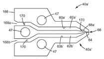
도 2는 도 1의 심들 중 하나의 평면도.
도 3은 도 1의 심들 중 다른 하나의 평면도.
도 4는 심들의 다른 반복 연속물을 함께 형성하는 4개의 인접한 심을 도시하는, 조립된 다이의 다이 슬롯의 부분의 부분 절결된 상세한 사시도.
도 5는 단면선이 웨브 횡단 방향인, 도 4에 도시된 바와 같이 조립된 다이에 의해 생성된 복합 층의 단면도.
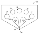
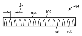
도 6은 심들의 다른 반복 연속물을 함께 형성하는 4개의 인접한 심을 도시하는, 조립된 다이의 다이 슬롯의 부분의 부분 절결된 상세한 사시도.
도 7은 단면선이 웨브 횡단 방향인, 도 6에 도시된 바와 같이 조립된 다이에 의해 생성된 복합 층의 단면도.
도 8은 복수의 심, 일 세트의 단부 블록, 구성요소들을 조립하기 위한 볼트, 및 압출될 재료를 위한 입구 피팅이 매니폴드 본체(manifold body) 내로 클램핑된, 압출 다이의 대안적인 예시적인 실시예의 분해 사시도.
도 9는 도 2가 도 1과 관련되는 방식과 동일하게 도 8에 관련되는, 도 8의 심들 중 하나의 평면도.
도 10은 도 3이 도 1과 관련되는 방식과 동일하게 도 18에 관련되는, 도 8의 심들 중 다른 하나의 평면도.
도 11은 조립된 상태의 도 8의 실시예의 사시도.1 is a composite described herein comprising a plurality of shims, a set of end blocks, bolts for assembling components, and inlet fittings for the material to be extruded An exploded perspective view of an exemplary embodiment of a set of extrusion die elements for producing a layer.
2 is a plan view of one of the shims of FIG. 1;
3 is a plan view of another one of the shims of FIG.
4 is a partially cutaway detailed perspective view of the portion of the die slot of the assembled die, showing four adjacent shims together forming another repeating series of shims;
FIG. 5 is a cross sectional view of the composite layer produced by the assembled die as shown in FIG. 4, the section line being in a cross-web direction; FIG.
6 is a partially cutaway detailed perspective view of a portion of the die slot of the assembled die, showing four adjacent shims forming together another repeating series of shims.
FIG. 7 is a cross sectional view of the composite layer produced by the assembled die as shown in FIG. 6, the section line being in a cross-web direction; FIG.
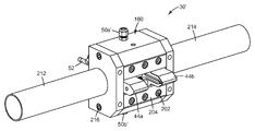
8 illustrates an alternative exemplary embodiment of an extrusion die in which a plurality of shims, a set of end blocks, bolts for assembling components, and inlet fittings for the material to be extruded are clamped into a manifold body. Exploded perspective view.
9 is a plan view of one of the shims of FIG. 8, relating to FIG. 8 in the same manner as FIG. 2 relates to FIG. 1;
10 is a plan view of another one of the shims of FIG. 8, relating to FIG. 18 in the same manner as FIG. 3 relates to FIG. 1;
11 is a perspective view of the embodiment of FIG. 8 in an assembled state;
일부 실시예에서, 본 발명에 사용되는 압출 다이(extrusion die)는, 서로 인접하게 위치되며 제1 공동, 제2 공동, 및 다이 슬롯(die slot)을 함께 한정하는 복수의 심을 포함하고, 다이 슬롯은 말단 개방부를 갖고, 복수의 심 각각이 말단 개방부의 일부분을 한정하며, 심들 중 적어도 제1 심은 제1 공동과 다이 슬롯 사이의 통로를 제공하고, 심들 중 적어도 제2 심은 제2 공동과 다이 슬롯 사이의 통로를 제공하며, 제2 공동과 다이 슬롯 사이의 통로를 제공하는 심들은 대향하는 제1 및 제2 주 표면들을 갖고, 통로는 제1 주 표면으로부터 제2 주 표면으로 연장한다.In some embodiments, an extrusion die used in the present invention includes a plurality of shims positioned adjacent to each other and defining together a first cavity, a second cavity, and a die slot, wherein the die slot Has a distal opening, each of the plurality of shims defining a portion of the distal opening, at least a first one of the shims providing a passage between the first cavity and the die slot, wherein at least a second of the shims is the second cavity and the die slot Shims providing a passage therebetween, the shims providing a passage between the second cavity and the die slots having opposing first and second major surfaces, the passageway extending from the first major surface to the second major surface.
일부 실시예에서, 본 발명에 사용되는 압출 다이는, 서로 인접하게 위치되며 제1 공동, 제2 공동, 및 다이 슬롯을 함께 한정하는 복수의 심을 포함하고, 다이 슬롯은 말단 개방부를 갖고, 복수의 심 각각이 말단 개방부의 일부분을 한정하며, 심들 중 적어도 제1 심은 제1 공동과 다이 슬롯 사이의 통로를 제공하고, 심들 중 적어도 제2 심은 제2 공동과 다이 슬롯 사이의 통로를 제공하며, 심들은 각각 대향하는 제1 및 제2 주 표면들 및 주 표면들에 수직한 두께를 갖고, 통로들은 각각의 심의 두께를 완전하게 통과하여 연장한다.In some embodiments, the extrusion die used in the present invention includes a plurality of shims positioned adjacent to each other and defining together a first cavity, a second cavity, and a die slot, the die slot having a distal opening, Each of the shims defines a portion of the distal opening, at least a first of the shims providing a passage between the first cavity and the die slot, at least a second of the shims providing a passage between the second cavity and the die slot, They each have a thickness perpendicular to the opposing first and second major surfaces and the major surfaces, and the passages extend completely through the thickness of each shim.
일부 실시예에서, 본 발명에 사용되는 압출 다이는, 서로 인접하게 위치되며 제1 공동, 제2 공동, 및 다이 슬롯을 함께 한정하는 복수의 심을 포함하고, 다이 슬롯은 말단 개방부를 갖고, 복수의 심 각각이 말단 개방부의 일부분을 한정하며, 심들 중 적어도 제1 심은 제1 공동과 다이 슬롯 사이의 도관을 제공하고, 심들 중 적어도 제2 심은 제2 공동과 다이 슬롯 사이의 도관을 제공하며, 220℃에서 300 Pa*s의 점도를 가진 유체가 압출 다이를 통해 압출되는 경우, 유체는 2000/초 미만의 전단율(shear rate)을 갖는다.In some embodiments, the extrusion die used in the present invention includes a plurality of shims positioned adjacent to each other and defining together a first cavity, a second cavity, and a die slot, the die slot having a distal opening, Each shim defines a portion of the distal opening, at least a first of the shims providing a conduit between the first cavity and the die slot, and at least a second of the shims providing a conduit between the second cavity and the die slot, 220 When a fluid with a viscosity of 300 Pa * s at ° C is extruded through an extrusion die, the fluid has a shear rate of less than 2000 / second.
일부 실시예에서, 본 발명에 사용되는 압출 다이는, 서로 인접하게 위치되며 제1 공동, 제2 공동, 및 다이 슬롯을 함께 한정하는 복수의 심을 포함하고, 다이 슬롯은 말단 개방부를 갖고, 복수의 심 각각이 말단 개방부의 일부분을 한정하며, 심들 중 적어도 제1 심은 제1 공동과 다이 슬롯 사이의 통로를 제공하고, 심들 중 적어도 제2 심은 제2 공동과 다이 슬롯 사이의 통로를 제공하며, 심들 중 적어도 하나는 제1 또는 제2 공동 중 어느 공동과 다이 슬롯 사이에서도 도관을 제공하지는 않는 스페이서 심(spacer shim)이다.In some embodiments, the extrusion die used in the present invention includes a plurality of shims positioned adjacent to each other and defining together a first cavity, a second cavity, and a die slot, the die slot having a distal opening, Each of the shims defines a portion of the distal opening, at least a first of the shims providing a passage between the first cavity and the die slot, at least a second of the shims providing a passage between the second cavity and the die slot, At least one of which is a spacer shim that does not provide conduit between any of the first or second cavities and the die slot.
일반적으로, 본 명세서에 기술된 복합 층을 제조하는 방법은,In general, the method of making a composite layer described herein,
원하는 복합 층 구성을 제공하도록 배열된 본 명세서에 기술된 압출 다이를 제공하는 단계;Providing an extrusion die as described herein arranged to provide a desired composite layer configuration;
제1 압출가능 중합체 재료를 제1 공동 내로 공급하는 단계;Feeding a first extrudable polymeric material into the first cavity;
제2 압출가능 중합체 재료를 제2 공동 내로 공급하는 단계; 및Feeding a second extrudable polymeric material into the second cavity; And
제1 및 제2 중합체 재료들을 다이 슬롯을 통해 그리고 말단 개방부를 통해 압출하여 복합 층을 제공하는 단계를 포함한다.Extruding the first and second polymeric materials through the die slot and through the terminal opening to provide a composite layer.
일부 실시예에서, 본 명세서에 기술된 복합 층을 제조하는 방법은,In some embodiments, a method of making a composite layer described herein,
원하는 복합 층 구성을 제공하도록 배열된 본 명세서에 기술된 압출 다이 - 압출 다이는, 서로 인접하게 위치되며 제1 공동, 제2 공동, 및 다이 슬롯을 함께 한정하는 복수의 심을 포함하고, 다이 슬롯은 말단 개방부를 갖고, 복수의 심 각각이 말단 개방부의 일부분을 한정하며, 심들 중 적어도 제1 심은 제1 공동과 다이 슬롯 사이의 도관을 제공하고, 심들 중 적어도 제2 심은 제2 공동과 다이 슬롯 사이의 도관을 제공함 - 를 제공하는 단계;The extrusion die-extrusion dies described herein arranged to provide a desired composite layer configuration include a plurality of shims positioned adjacent to each other and defining together a first cavity, a second cavity, and a die slot, wherein the die slot is Having a distal opening, each of the plurality of shims defining a portion of the distal opening, at least a first one of the shims providing a conduit between the first cavity and the die slot, wherein at least a second one of the shims is between the second cavity and the die slot Providing a conduit of;
제1 압출가능 중합체 재료를 제1 공동 내로 공급하는 단계;Feeding a first extrudable polymeric material into the first cavity;
제2 압출가능 중합체 재료를 제2 공동 내로 공급하는 단계; 및Feeding a second extrudable polymeric material into the second cavity; And
제1 및 제2 중합체 재료들을 다이 슬롯을 통해 그리고 말단 개방부를 통해 압출하여, 제1 중합체 재료의 적어도 하나의 별개의 영역 및 제2 중합체 재료의 적어도 하나의 별개의 영역을 포함하는 복합 층을 제공하는 단계를 포함한다.Extruding the first and second polymeric materials through the die slot and through the terminal opening to provide a composite layer comprising at least one separate region of the first polymeric material and at least one separate region of the second polymeric material. It includes a step.
전형적으로, 심들 모두가 통로를 갖지는 않으며; 일부는 제1 또는 제2 공동 중 어느 공동과 다이 슬롯 사이에서도 도관을 제공하지는 않는 스페이서 심일 수 있다. 제1 공동과 다이 슬롯 사이의 통로를 제공하는 심들의 개수는 제2 공동과 다이 슬롯 사이의 통로를 제공하는 심들의 개수와 동일하거나 동일하지 않을 수 있다.Typically not all shims have passages; Some may be spacer shims that do not provide conduit between any of the first or second cavities and the die slot. The number of shims providing the passage between the first cavity and the die slot may or may not be the same as the number of shims providing the passage between the second cavity and the die slot.
일부 실시예에서, 본 명세서에 기술된 압출 다이는 복수의 심을 지지하기 위한 한 쌍의 단부 블록을 포함한다. 이들 실시예에서, 심들 중 하나 또는 모두가 단부 블록들의 쌍 사이에서의 커넥터의 통과를 위한 하나 이상의 관통 구멍을 각각 갖는 것이 편리할 수 있다. 그러한 관통 구멍 내에 배치되는 볼트는 심을 단부 블록에 조립하기 위한 하나의 편리한 수단이지만, 당업자는 압출 다이를 조립하기 위한 다른 대안을 인식할 수 있다. 일부 실시예에서, 적어도 하나의 단부 블록은 공동들 중 하나 또는 둘 모두의 내로의 유체 재료의 도입을 위한 입구 포트를 갖는다.In some embodiments, the extrusion die described herein includes a pair of end blocks for supporting a plurality of shims. In these embodiments, it may be convenient for one or both shims to each have one or more through holes for the passage of a connector between a pair of end blocks. Bolts disposed in such through holes are one convenient means for assembling the shim to the end block, but one skilled in the art can recognize other alternatives for assembling the extrusion die. In some embodiments, the at least one end block has an inlet port for introduction of fluid material into one or both of the cavities.
일부 실시예에서, 심들은 다양한 유형의 심들의 반복 연속물을 제공하는 계획에 따라 조립될 것이다. 반복 연속물은 반복마다 2개 이상의 심을 가질 수 있다. 제1 예의 경우, 2-심 반복 연속물이 제1 공동과 다이 슬롯 사이의 도관을 제공하는 심 및 제2 공동과 다이 슬롯 사이의 도관을 제공하는 심을 포함할 수 있다. 제2 예의 경우, 4-심 반복 연속물이 제1 공동과 다이 슬롯 사이의 도관을 제공하는 심, 스페이서 심, 제2 공동과 다이 슬롯 사이의 도관을 제공하는 심, 및 스페이서 심을 포함할 수 있다.In some embodiments, shims will be assembled according to a scheme that provides a repeating series of shims of various types. Repeating sequences may have two or more shims per iteration. For the first example, the two-seater repeating series may include a shim providing a conduit between the first cavity and the die slot and a shim providing a conduit between the second cavity and the die slot. For a second example, the four-season repeating series can include a shim providing a conduit between the first cavity and the die slot, a spacer shim, a shim providing a conduit between the second cavity and the die slot, and a spacer shim.
예를 들어 심들의 반복 연속물 내의 통로들의 형상은 동일하거나 상이할 수 있다. 예를 들어, 일부 실시예에서, 제1 공동과 다이 슬롯 사이의 도관을 제공하는 심들은 제2 공동과 다이 슬롯 사이의 도관을 제공하는 심들에 비해 유동 제한부를 가질 수도 있다. 예를 들어 심들의 반복 연속물 내의 말단 개방부의 폭은 동일하거나 상이할 수 있다. 예를 들어, 제1 공동과 다이 슬롯 사이의 도관을 제공하는 심들에 의해 제공되는 말단 개방부의 부분은 제2 공동과 다이 슬롯 사이의 도관을 제공하는 심들에 의해 제공되는 말단 개방부의 부분보다 좁을 수 있다.For example, the shapes of the passageways in the repeating series of shims can be the same or different. For example, in some embodiments, shims providing a conduit between a first cavity and a die slot may have flow restriction compared to shims providing a conduit between a second cavity and a die slot. For example, the width of the terminal openings in the repeating series of shims can be the same or different. For example, the portion of the distal opening provided by the shims providing the conduit between the first cavity and the die slot may be narrower than the portion of the distal opening provided by the shims providing the conduit between the second cavity and the die slot. have.
예를 들어 심들의 반복 연속물 내의 다이 슬롯의 형상은 동일하거나 상이할 수 있다. 예를 들어, 4-심 반복 연속물이 제1 공동과 다이 슬롯 사이의 도관을 제공하는 심, 스페이서 심, 제2 공동과 다이 슬롯 사이의 도관을 제공하는 심, 및 스페이서 심을 갖도록 채용될 수 있고, 제2 공동과 다이 슬롯 사이의 도관을 제공하는 심들은 말단 개방부의 양 에지로부터 변위된 좁아진 통로를 갖는다.For example, the shape of the die slot in the repeating series of shims can be the same or different. For example, a four-core repeating series may be employed to have a shim providing a conduit between the first cavity and the die slot, a spacer shim, a shim providing a conduit between the second cavity and the die slot, and a spacer shim, The shims providing the conduit between the second cavity and the die slot have a narrow passageway displaced from both edges of the distal opening.
일부 실시예에서, 조립된 심들(편리하게는 단부 블록들 사이에서 볼트체결됨)은 매니폴드 본체 내에서 추가로 클램핑된다. 매니폴드 본체는 적어도 하나(또는 그 이상; 보통 2개)의 매니폴드를 내부에 가지며, 매니폴드는 출구를 갖는다. 팽창 시일(expansion seal)(예컨대, 구리로 제조됨)이 매니폴드 본체와 심들을 밀봉하도록 배치되어, 팽창 시일은 공동들 중 적어도 하나의 일부분(일부 실시예에서, 제1 및 제2 공동 둘 모두의 일부분)을 한정하고, 팽창 시일은 매니폴드와 공동 사이의 도관을 제공한다.In some embodiments, the assembled shims (conveniently bolted between end blocks) are further clamped within the manifold body. The manifold body has at least one (or more; usually two) manifolds therein and the manifold has an outlet. An expansion seal (eg, made of copper) is arranged to seal the manifold body and the shims such that the expansion seal is part of at least one of the cavities (in some embodiments, both the first and second cavities). A portion thereof, the inflation seal provides a conduit between the manifold and the cavity.
본 명세서에 기술된 다이의 일부 실시예에서, 제1 통로는 제1 평균 길이 및 제1 평균 수직 단치수(minor perpendicular dimension)를 가지며, 제1 평균 길이 대 제1 평균 수직 단치수의 비는 200:1(일부 실시예에서, 150:1, 100:1, 75:1, 50:1, 또는 심지어 10:1) 내지 1:1(일부 실시예에서, 2:1) 초과(전형적으로는, 50:1 내지 2:1)의 범위이고, 제2 통로는 제2 평균 길이 및 제2 평균 수직 단치수를 가지며, 제2 평균 길이 대 제2 평균 수직 단치수의 비는 200:1(일부 실시예에서, 150:1, 100:1, 75:1, 50:1, 또는 심지어 10:1) 내지 1:1(일부 실시예에서, 2:1) 초과(전형적으로는, 50:1 내지 2:1)의 범위이다.In some embodiments of the dies described herein, the first passageway has a first average length and a first average vertical dimension, and the ratio of the first average length to the first average vertical short dimension is 200 : 1 (in some embodiments, 150: 1, 100: 1, 75: 1, 50: 1, or even 10: 1) to 1: 1 (in some embodiments, 2: 1) and greater than (typically, 50: 1 to 2: 1), the second passageway having a second average length and a second average vertical short dimension, and the ratio of the second average length to the second average vertical short dimension is 200: 1 (some implementations) In an example, 150: 1, 100: 1, 75: 1, 50: 1, or even 10: 1) to 1: 1 (in some embodiments, 2: 1) greater than (typically 50: 1 to 2) The range is: 1).
본 명세서에 기술된 다이의 일부 실시예에서, 220℃에서 300 Pa*s의 점도를 가진 유체가 압출 다이를 통해 압출되는 경우, 유체는 2000/초 미만의 전단율을 가지며, 점도는 모세관 유량계(영국 웨스트 미들랜드 소재의 로잔드 프리시젼 엘티디.(Rosand Precision Ltd.)로부터 상표명 "어드밴스드 리오미터 시스템(Advanced Rheometer System)"; 모델 RH-2000으로 입수가능함)를 사용하여 결정된다.In some embodiments of the dies described herein, when a fluid with a viscosity of 300 Pa * s at 220 ° C. is extruded through an extrusion die, the fluid has a shear rate of less than 2000 / sec, and the viscosity is a capillary flow meter ( It is determined using the trade name “Advanced Rheometer System” available from Model RH-2000 from Rosand Precision Ltd., West Midlands, UK.
본 발명의 다른 태양에 따르면, 복합 층을 제조하는 방법이 제공되며, 방법은, 서로 인접하게 위치되며 제1 공동, 제2 공동, 및 다이 슬롯을 함께 한정하는 복수의 심을 포함하는 압출 다이 - 다이 슬롯은 말단 개방부를 갖고, 복수의 심 각각이 말단 개방부의 일부분을 한정하며, 심들 중 적어도 제1 심은 제1 공동과 다이 슬롯 사이의 도관을 제공하고, 심들 중 적어도 제2 심은 제2 공동과 다이 슬롯 사이의 도관을 제공함 - 를 제공하는 단계; 제1 압출가능 중합체 재료를 제1 공동 내로 공급하는 단계; 제2 압출가능 중합체 재료를 제2 공동 내로 공급하는 단계; 제1 및 제2 중합체 재료들을 다이 슬롯을 통해 그리고 말단 개방부를 통해 압출하여, 제1 중합체 재료의 적어도 하나의 별개의 영역 및 제2 중합체 재료의 적어도 하나의 별개의 영역을 포함하는 복합 층을 제공하는 단계를 포함한다. 이러한 관계에서 사용되는 바와 같이, "압출가능 중합체 재료"는 압출된 때 100% 고형물을 갖는 중합체 재료를 지칭한다.According to another aspect of the present invention, a method of making a composite layer is provided, the method comprising: an extrusion die-die comprising a plurality of shims positioned adjacent to each other and defining together a first cavity, a second cavity, and a die slot The slot has a distal opening, each of the plurality of shims defining a portion of the distal opening, at least a first of the shims providing a conduit between the first cavity and the die slot, and at least a second of the shims having a second cavity and die Providing a conduit between slots; Feeding a first extrudable polymeric material into the first cavity; Feeding a second extrudable polymeric material into the second cavity; Extruding the first and second polymeric materials through the die slot and through the terminal opening to provide a composite layer comprising at least one separate region of the first polymeric material and at least one separate region of the second polymeric material. It includes a step. As used in this relationship, “extrudeable polymeric material” refers to a polymeric material that has 100% solids when extruded.
방법을 실시함에 있어서, 제1 및 제2 중합체 재료들은 간단히 냉각에 의해 고화될 수도 있다. 이는 편리하게는 주위 공기에 의해 수동적으로, 또는 예를 들어 압출된 제1 및 제2 중합체 재료들을 냉각된 표면(예컨대, 냉각된 롤(chilled roll)) 상에서 급랭함으로써 능동적으로 달성될 수 있다. 일부 실시예에서, 제1 및/또는 제2 중합체 재료들은, 예를 들어 전자기 또는 입자 방사에 의해 이루어질 수 있는, 고화되도록 가교결합될 것을 필요로 하는 저분자량 중합체이다.In practicing the method, the first and second polymer materials may be solidified by simply cooling. This may conveniently be accomplished manually by ambient air or actively, for example by quenching the extruded first and second polymer materials on a cooled surface (eg, a chilled roll). In some embodiments, the first and / or second polymeric materials are low molecular weight polymers that need to be crosslinked to solidify, which may be made, for example, by electromagnetic or particle radiation.
일부 실시예에서, 다이 말단 개방부는 적어도 100:1(일부 실시예에서, 적어도 500:1, 1000:1, 2500:1, 또는 심지어 적어도 5000:1까지)의 종횡비(aspect ratio)를 갖는다.In some embodiments, the die end openings have an aspect ratio of at least 100: 1 (in some embodiments, at least 500: 1, 1000: 1, 2500: 1, or even at least 5000: 1).
본 명세서에 기술된 방법은 다양한 압력 수준에서 작동될 수 있지만, 많은 편리한 용융 중합체 작동에 대해 제1 공동 내의 제1 중합체 재료 및/또는 제2 공동 내의 중합체 재료는 689 ㎪ (100 psi) 초과의 압력에서 유지된다. 제1 및 제2 공동들을 통해 처리되는 재료의 양은 동일하거나 상이할 수 있다. 특히, 체적 기준으로, 말단 개방부를 통과하는 제1 중합체 재료 대 말단 개방부를 통과하는 제2 중합체 재료의 비는 5:1, 10:1, 20:1, 25:1, 50:1, 75:1 초과, 또는 심지어 100:1 초과일 수 있다.Although the methods described herein can be operated at various pressure levels, for many convenient melt polymer operations, the first polymer material in the first cavity and / or the polymer material in the second cavity may be pressured above 100 psi. Is maintained at. The amount of material processed through the first and second cavities can be the same or different. In particular, on a volume basis, the ratio of the first polymeric material through the terminal opening to the second polymeric material through the terminal opening is 5: 1, 10: 1, 20: 1, 25: 1, 50: 1, 75: Greater than 1, or even greater than 100: 1.
방법은 다이 슬롯에 대한 일정 범위의 크기에 대해 작동될 수 있다. 일부 실시예에서, 제1 및 제2 중합체 재료들이 필요한 기간보다 오랫동안 고화되지 않은 상태에서 접촉하여 유지되지 않는 것이 편리할 수 있다. 제1 중합체 재료 및 제2 중합체 재료가 말단 개방부로부터 25 ㎜ 이하(일부 실시예에서, 20 ㎜, 15 ㎜, 10 ㎜, 5 ㎜ 이하, 또는 심지어 1 ㎜ 이하)의 거리에서 서로 접촉하도록 본 발명의 방법의 실시예를 작동시키는 것이 가능하다. 방법은 0.025 ㎜ 내지 1 ㎜ 범위의 두께를 갖는 복합 층을 제조하도록 사용될 수 있다.The method may be operated for a range of sizes for die slots. In some embodiments, it may be convenient for the first and second polymeric materials not to remain in contact without being solidified for longer than necessary. The present invention such that the first polymer material and the second polymer material contact each other at a distance of 25 mm or less (in some embodiments, 20 mm, 15 mm, 10 mm, 5 mm or less, or even 1 mm or less) from the terminal opening. It is possible to operate an embodiment of the method. The method can be used to produce composite layers having a thickness in the range of 0.025 mm to 1 mm.
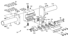
도 1을 참조하면, 본 발명에 따른 압출 다이(30)의 예시적인 실시예의 분해도가 예시되어 있다. 압출 다이(30)는 복수의 심(40)을 포함한다. 일부 실시예에서, 2개의 단부 블록들(44a, 44b) 사이에 압축된, 다양한 유형(심들(40a, 40b, 40c))의 매우 많은 수의 매우 얇은 심들(40)(전형적으로, 수천개의 심들; 일부 실시예에서, 1000개, 2000개, 3000개, 4000개, 5000개, 6000개, 7000개, 8000개, 9000개 이상, 또는 심지어 10,000개 이상)이 존재할 것이다. 편리하게는, 체결구(예컨대, 너트(48) 상으로 나사결합된 관통 볼트(46))가 구멍(47)을 통과함으로써 압출 다이(30)를 위한 구성요소들을 조립하도록 사용된다. 입구 피팅(50a, 50b)이 압출될 재료를 압출 다이(30) 내로 도입하도록 각각의 단부 블록(44a, 44b) 상에 제공된다. 일부 실시예에서, 입구 피팅(50a, 50b)은 통상적인 유형의 멜트 트레인(melt train)에 연결된다. 일부 실시예에서, 카트리지 히터(52)가 압출될 재료를 다이 내에 있는 동안 원하는 온도로 유지하기 위해 압출 다이(30) 내의 리셉터클(54) 내로 삽입된다.1, an exploded view of an exemplary embodiment of an extrusion die 30 according to the present invention is illustrated. The extrusion die 30 includes a plurality of
이제 도 2를 참조하면, 도 1의 심(40a)의 평면도가 예시되어 있다. 심(40a)은 제1 개구(60a) 및 제2 개구(60b)를 갖는다. 압출 다이(30)가 조립된 때, 심들(40) 내의 제1 개구들(60a)이 제1 공동(62a)의 적어도 일부분을 함께 한정한다. 유사하게, 심들(40) 내의 제2 개구들(60b)이 제2 공동(62b)의 적어도 일부분을 함께 한정한다. 압출될 재료가 입구 포트(50a)를 통해 제1 공동(62a)으로 편리하게 진입하고, 동시에 압출될 재료가 입구 포트(50b)를 통해 제2 공동(62b)으로 편리하게 진입한다. 심(40a)은 슬롯(66)에서 종료하는 다이 슬롯(64)을 갖는다. 심(40a)은 제1 공동(62a)과 다이 슬롯(64) 사이의 도관을 제공하는 통로(68a)를 추가로 갖는다. 도 1의 실시예에서, 심(40b)은, 대신에 제2 공동(62b)과 다이 슬롯(64) 사이의 도관을 제공하는 통로를 갖는, 심(40a)의 거울상(reflection)이다.Referring now to FIG. 2, a plan view of
이제 도 3을 참조하면, 도 1의 심(40c)의 평면도가 예시되어 있다. 심(40c)은 각각의 제1 또는 제2 공동(62a, 62b) 중 어느 공동과 다이 슬롯(64) 사이에서도 도관을 갖지 않는다.Referring now to FIG. 3, a plan view of
이제 도 4를 참조하면, 도 1의 다이(30)와 유사하게 조립된 다이 슬롯의 부분의 부분 절결된 상세한 사시도가 예시되어 있다. 도 4는 심들의 반복 연속물을 함께 편리하게 형성하는 4개의 인접한 심을 도시하지만, 이러한 실시예에서 도 1의 연속물 내에 도시된 바와 같은 심(40b)은 심(90)으로 대체되었다. 심(40b)과 유사하게, 심(90)은 공동(62b)의 일부분으로 이어지는 통로(68)를 갖는다. 그러나, 심(90)은 통로(68)를 통해 다이 슬롯(64)으로 흘러 들어가는 면적을 감소시키는 유동 제한부(92)를 갖는다. 다이(30)와 유사한 다이가 이러한 방식으로 이러한 유형의 심들과 조립된 때, 그리고 2가지의 유동가능 중합체 함유 조성물이 압력 하에서 공동(62a, 62b)으로 도입되면, 대체로 도 5에 도시된 바와 같은 공압출된 복합 층이 생성된다.Referring now to FIG. 4, a partially cutaway detailed perspective view of a portion of a die slot assembled similarly to die 30 of FIG. 1 is illustrated. 4 illustrates four adjacent shims that conveniently form a repeating series of shims together, in this embodiment shims 40b as shown in the series of FIG. 1 have been replaced with
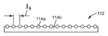
이제 도 5를 참조하면, 도 4에 도시된 바와 같이 조립된 다이에 의해 생성된 복합 층의 단면도가 예시되어 있다. 복합 층(94)은 공동(62b)으로부터 분배된, 재료(96b)의 반복 수직 영역을 갖는다. 재료(96b)의 이들 영역은 재료(96a) 내에 부분적으로 둘러싸여서, 재료(96b)의 면적은 복합 층(94)의 제1 주 표면(98) 상에서 노출되고 복합 층(94)의 제2 주 표면(100) 상에서는 노출되지 않는다.Referring now to FIG. 5, a cross-sectional view of a composite layer produced by a die assembled as shown in FIG. 4 is illustrated.
이제 도 6을 참조하면, 도 1의 다이(30)와 유사한 조립된 다이의 다이 슬롯의 부분의 부분 절결된 상세한 사시도가 예시되어 있다. 도 6은 심들의 반복 연속물을 함께 편리하게 형성하는 4개의 인접한 심을 도시한다. 도면이 배향된 대로 좌측으로부터 우측으로의 연속물 중 첫번째 것은 심(109)이다. 이러한 도면에서, 공동(62a)의 일부분으로 이어지는 통로(68a)를 볼 수 있다. 연속물 중 두번째 것은 스페이서 심(40c)이다. 연속물 중 세번째 것은 심(110)이다. 도 6에 도시되지는 않았지만, 심(110)은 도면이 배향된 대로 하향으로 이어지고 제2 공동(62b)과의 도관을 제공하는 통로(68b)를 갖는다. 연속물 중 네번째 것은 제2 스페이서 심(40c)이다. 여기서 예시된 실시예는 슬롯(66)이 모든 심에 대해 동일한 높이일 필요가 없는 계획을 대표한다. 이하 기술되는 도 7에서 더욱 특정하게 주목하는 바와 같이, 제1 공동(62a) 내로 유동하는 재료는 공동(62b)으로부터 압출되는 재료(114b)로부터 형성된 표면으로부터 상향으로 연장하는 일련의 리브(114a)를 생성할 것이다. 다이(30)와 유사한 다이가 이러한 방식으로 이러한 유형의 심들과 조립된 때, 그리고 2가지의 유동가능 중합체 함유 조성물이 압력 하에서 공동(62a, 62b)으로 도입되면, 대체로 도 7에 도시된 바와 같은 공압출된 복합 층(112)이 생성된다.Referring now to FIG. 6, a partially cut away detailed perspective view of a portion of a die slot of an assembled die similar to die 30 of FIG. 1 is illustrated. 6 shows four adjacent shims conveniently forming together a repeating series of shims. The first of the series from left to right as the figure is oriented is the
이제 도 7을 참조하면, 도 6에 도시된 바와 같이 조립된 다이에 의해 생성된 복합 층의 단면도가 예시되어 있다. 도 7에 대한 단면선은 완성된 복합 층의 웨브 횡단 방향이다. 복합 층(112)은 복합 층(114b) 상의 리브를 형성하는 재료(114a)의 반복 영역을 갖는다.Referring now to FIG. 7, a cross-sectional view of a composite layer produced by a die assembled as shown in FIG. 6 is illustrated. The cross section line for FIG. 7 is the web cross direction of the finished composite layer.
이제 도 8을 참조하면, 본 발명에 따른 압출 다이(30')의 대안적인 실시예의 분해 사시도가 예시되어 있다. 압출 다이(30')는 복수의 심(40')을 포함한다. 도시된 실시예에서, 2개의 단부 블록들(44a', 44b') 사이에 압축된, 다양한 유형(심들(40a', 40b', 40''c'))의 매우 많은 수의 매우 얇은 심들(40')이 존재한다. 편리하게는, 관통 볼트(46) 및 너트(48)가 심(40')을 단부 블록(44a', 44b')에 조립하기 위해 사용된다.Referring now to FIG. 8, an exploded perspective view of an alternative embodiment of an extrusion die 30 ′ according to the present invention is illustrated. The extrusion die 30 'includes a plurality of shims 40'. In the illustrated embodiment, a very large number of very thin shims of various types (
이러한 실시예에서, 단부 블록(44a', 44b')은 압축 블록(204)을 심(40') 및 단부 블록(44a', 44b')에 대항하여 가압하는 볼트(202)에 의해 매니폴드 본체(160)에 체결된다. 입구 피팅(50a', 50b')이 또한 매니폴드 본체(160)에 부착된다. 이들은, 단지 출구(206a, 206b)만을 도 8에서 볼 수 있는 2개의 내부 매니폴드와 연통한다. 입구 피팅(50a', 50b')을 통해 본체(160)로 별개로 진입하는 용융 중합체 재료는 내부 매니폴드를 통해, 출구(206a, 206b) 밖으로, 정렬 플레이트(210) 내의 통로(208a, 208b)를 통해 그리고 개방부(168a, 168b)(도 9에 도시됨) 내로 통과한다.In this embodiment, the end blocks 44a ', 44b' are manifold bodies by
팽창 시일(164)이 심(40')과 정렬 플레이트(210) 사이에 배치된다. 팽창 시일(164)은, 심(40')과 함께, 제1 및 제2 공동(도 9의 62a, 62b)의 체적을 함께 한정한다. 팽창 시일은 압출되는 용융 중합체와 연관된 고온을 견디며, 조립된 심(40')의 약간 평탄하지 않을 수도 있는 후방 표면에 대항하여 밀봉한다. 팽창 시일(164)은 심(40') 및 매니폴드 본체(160) 둘 모두에 대해 편리하게 사용되는 스테인레스강보다 높은 열 팽창 상수를 가진 구리로부터 제조될 수 있다. 다른 유용한 팽창 시일(164) 재료는 실리카 충전제를 가진 폴리테트라플루오로에틸렌(PTFE) 가스켓(미국 뉴욕주 팔마이라 소재의 갈락 실링 테크놀로지스(Garlock Sealing Technologies)로부터 상표명 "자일론(GYLON) 3500" 및 "자일론 3545"로 입수가능함)을 포함한다.An
카트리지 히터(52)가 본체(160) 내로, 편리하게는 도 1의 리셉터클(54)과 유사한 매니폴드 본체(160)의 배면 내의 리셉터클 내로 삽입될 수 있다. 카트리지 히터가 슬롯(66)에 수직한 방향으로 삽입되는 도 8의 실시예는 다이를 그 폭에 걸쳐 차별적으로 가열하는 것을 용이하게 한다는 점에서 이점을 갖는다. 매니폴드 본체(160)는 지지체(212, 214)에 의해 장착되도록 편리하게 파지되며, 볼트(216)에 의해 매니폴드 본체(160)에 편리하게 부착된다.The
이제 도 9를 참조하면, 도 8의 심(40a')의 평면도가 예시되어 있다. 심(40a')은 제1 개구(60a') 및 제2 개구(60b')를 갖는다. 압출 다이(30')가 조립된 때, 심들(40') 내의 제1 개구들(60a')이 제1 공동(62a')의 적어도 일부분을 함께 한정한다. 유사하게, 심들(40') 내의 제2 개구들(60b')이 제1 공동(62a')의 적어도 일부분을 함께 한정한다. 심(40a')의 기부 단부(166)는 압출 다이(30')가 조립된 때 팽창 시일(164)과 접촉한다. 압출될 재료가 팽창 시일(164) 내의 개구를 통해 그리고 심 개방부(168a)를 통해 제1 공동(62a)으로 편리하게 진입한다. 유사하게, 압출될 재료가 팽창 시일(164) 내의 개구를 통해 그리고 심 개방부(168a)를 통해 제1 공동(62a)으로 편리하게 진입한다.Referring now to FIG. 9, a plan view of
심(40a')은 슬롯(66)에서 종료하는 다이 슬롯(64)을 갖는다. 심(40a')은 제1 공동(62a')과 다이 슬롯(64) 사이의 도관을 제공하는 통로(68a')를 추가로 갖는다. 도 8의 실시예에서, 심(40b')은, 대신에 제2 공동(62b')과 다이 슬롯(64) 사이의 도관을 제공하는 통로를 갖는, 심(40a')의 거울상이다. 보강 부재(170)가 인접한 공동들 및 통로들을 차단할 것으로 생각될 수도 있지만, 이는 오해이다 - 유동은 압출 다이(30')가 완전하게 조립된 때 도면 차원의 평면에 수직한 경로를 갖는다.
이제 도 10을 참조하면, 도 8의 심(40c')의 평면도가 예시되어 있다. 심(40c')은 각각의 제1 또는 제2 공동(62a', 62b') 중 어느 공동과 다이 슬롯(64) 사이에서도 도관을 갖지 않는다.Referring now to FIG. 10, a plan view of
이제 도 11을 참조하면, 내부 부품들의 가시화를 가능하게 하도록 생략된 대부분의 심(40')을 제외한, 도 8의 압출 다이(30')의 사시도가 조립된 상태로 예시되어 있다. 도 8 및 도 11의 실시예가 도 1의 실시예보다 더욱 복잡하지만, 이는 몇 가지 이점을 가진다. 첫째, 이는 가열에 대한 더 정교한 제어를 가능하게 한다. 둘째, 매니폴드 본체(160)의 사용은 심(40')이 중앙-공급식(center-fed)으로 되게 하여, 압출된 필름에서의 측면간(side-to-side) 균일성을 증가시킨다. 셋째, 전방으로 돌출하는 심(40')은 말단 개방부(66)가 혼잡한 제조 라인 상의 더 촘촘한 위치들 내로 맞춰지는 것을 가능하게 한다. 심은 전형적으로 0.05 ㎜ (2 밀) 내지 0.25 ㎜ (10 밀) 두께이지만, 예를 들어 0.025 ㎜ (1 밀) 내지 1 ㎜ (40 밀)의 두께를 포함하는 다른 두께가 또한 유용할 수 있다. 각각의 개별 심은, 바람직하게는 0.005 ㎜ (0.2 밀) 미만, 더 바람직하게는 0.0025 ㎜ (0.1 밀) 미만의 가변성을 갖고서, 대체로 균일한 두께를 가진다.Referring now to FIG. 11, a perspective view of the extrusion die 30 ′ of FIG. 8 is illustrated in an assembled state, except for the majority of
심은 전형적으로 금속, 바람직하게는 스테인레스강이다. 가열 사이클링으로 인한 크기 변화를 감소시키기 위해, 금속 심은 바람직하게는 열처리된다.The shim is typically a metal, preferably stainless steel. In order to reduce the size change due to heat cycling, the metal shims are preferably heat treated.
심은 와이어 전기 방전 및 레이저 기계가공을 포함하는 통상적인 기술에 의해 제조될 수 있다. 흔히, 복수의 심이, 복수의 시트를 적층하고 이어서 원하는 개방부들을 동시에 생성함으로써 동시에 제조된다. 유동 채널의 가변성은 0.025 ㎜ (1 밀) 이내, 더 바람직하게는 0.013 ㎜ (0.5 밀) 이내이다.Shims can be manufactured by conventional techniques, including wire electrical discharge and laser machining. Often, a plurality of shims are produced simultaneously by laminating a plurality of sheets and subsequently creating the desired openings. The variability of the flow channel is within 0.025 mm (1 mil), more preferably within 0.013 mm (0.5 mil).
본 명세서에 기술된 다이와 본 명세서에 기술된 방법으로부터의 압출에, 그리고 본 명세서에 기술된 복합 층에 적합한 중합체 재료는 폴리올레핀(예컨대, 폴리프로필렌 및 폴리에틸렌), 폴리비닐 클로라이드, 폴리스티렌, 나일론, 폴리에스테르(예컨대, 폴리에틸렌 테레프탈레이트) 및 이들의 공중합체와 블렌드를 포함하는 열가소성 수지를 포함한다. 본 명세서에 기술된 다이와 본 명세서에 기술된 방법으로부터의 압출에, 그리고 본 명세서에 기술된 복합 층에 적합한 중합체 재료는 또한 탄성중합체 재료(예컨대, ABA 블록 공중합체, 폴리우레탄, 폴리올레핀 탄성중합체, 폴리우레탄 탄성중합체, 메탈로센 폴리올레핀 탄성중합체, 폴리아미드 탄성중합체, 에틸렌 비닐 아세테이트 탄성중합체, 및 폴리에스테르 탄성중합체)를 포함한다. 본 명세서에 기술된 다이와 본 명세서에 기술된 방법으로부터의 압출을 위한, 그리고 본 명세서에 기술된 복합 층을 위한 예시적인 접착제는 아크릴레이트 공중합체 감압 접착제, 고무계 접착제(예컨대, 천연 고무, 폴리아이소부틸렌, 폴리부타디엔 부틸 고무, 스티렌 블록 공중합체 고무 등에 기반한 것들), 실리콘 폴리우레아 또는 실리콘 폴리옥사미드에 기반한 접착제, 폴리우레탄 유형 접착제, 및 폴리(비닐 에틸 에테르)와, 이들의 공중합체 또는 블렌드를 포함한다. 다른 바람직한 재료는, 예를 들어 스티렌-아크릴로니트릴, 셀룰로오스 아세테이트 부티레이트, 셀룰로오스 아세테이트 프로피오네이트, 셀룰로오스 트라이아세테이트, 폴리에테르 설폰, 폴리메틸 메타크릴레이트, 폴리우레탄, 폴리에스테르, 폴리카르보네이트, 폴리비닐 클로라이드, 폴리스티렌, 폴리에틸렌 나프탈레이트, 나프탈렌 다이카르복실산에 기반한 공중합체 또는 블렌드, 폴리올레핀, 폴리이미드, 이들의 혼합물 및/또는 조합을 포함한다.Suitable polymeric materials for extrusion from the dies described herein and the methods described herein, and for the composite layers described herein, include polyolefins (eg, polypropylene and polyethylene), polyvinyl chloride, polystyrene, nylon, polyester (Such as polyethylene terephthalate) and copolymers and blends thereof. Suitable polymeric materials for extrusion from the dies described herein and the methods described herein, and for the composite layers described herein, are also elastomeric materials (eg, ABA block copolymers, polyurethanes, polyolefin elastomers, poly Urethane elastomers, metallocene polyolefin elastomers, polyamide elastomers, ethylene vinyl acetate elastomers, and polyester elastomers). Exemplary adhesives for extrusion from the dies described herein and the methods described herein, and for the composite layers described herein include acrylate copolymer pressure sensitive adhesives, rubber based adhesives (eg, natural rubber, polyisobutyl). Ethylene, polybutadiene butyl rubber, styrene block copolymer rubber, and the like), silicone polyurea or silicone polyoxamide based adhesives, polyurethane type adhesives, and poly (vinyl ethyl ether) and copolymers or blends thereof Include. Other preferred materials are, for example, styrene-acrylonitrile, cellulose acetate butyrate, cellulose acetate propionate, cellulose triacetate, polyether sulfone, polymethyl methacrylate, polyurethane, polyester, polycarbonate, poly Copolymers or blends based on vinyl chloride, polystyrene, polyethylene naphthalate, naphthalene dicarboxylic acid, polyolefins, polyimides, mixtures and / or combinations thereof.
일부 실시예에서, 제1 및 제2 중합체 재료들은 각각 상이한 굴절률을 갖는다(즉, 하나가 다른 하나에 비해 상대적으로 더 높음).In some embodiments, the first and second polymer materials each have a different refractive index (ie, one is relatively higher than the other).
일부 실시예에서, 게다가 제1 및/또는 제2 중합체 재료는 기능적 목적(예컨대, 광학 효과) 및/또는 미적 목적(예컨대, 각각이 상이한 색상/음영을 가짐)을 위해 착색제(예컨대, 안료 및/또는 염료)를 포함한다. 적합한 착색제는 다양한 중합체 재료에의 사용에 대해 당업계에 공지되어 있는 것들이다. 착색제에 의해 부여되는 예시적인 색상은 백색, 흑색, 적색, 분홍색, 주황색, 황색, 녹색, 옥색, 자주색, 및 청색을 포함한다. 일부 실시예에서, 제1 및/또는 제2 중합체 재료가 소정 정도의 불투명도를 갖는 것이 바람직한 관점이다. 사용되는 착색제의 유형 및 불투명도의 원하는 정도뿐만 아니라, 예를 들어 복합 물품의 특정 구역의 크기 및 형상이 사용되는 착색제의 양에 영향을 준다. (예컨대, 원하는 색상, 색조, 불투명도, 투과율 등을 달성하기 위해) 특정 실시예에서 사용될 착색제(들)의 양은 당업자에 의해 용이하게 결정될 수 있다. 필요할 경우, 제1 및 제2 중합체 재료들은 동일하거나 상이한 색상을 갖도록 제형화될 수 있다.In some embodiments, the first and / or second polymeric materials may furthermore contain colorants (eg, pigments and / or for functional purposes (eg, optical effects) and / or aesthetic purposes (eg, each having a different color / shading). Or dyes). Suitable colorants are those known in the art for use in various polymeric materials. Exemplary colors imparted by the colorant include white, black, red, pink, orange, yellow, green, turquoise, purple, and blue. In some embodiments, it is a preferred aspect that the first and / or second polymeric material has a degree of opacity. The desired degree of type and opacity of the colorant used, as well as the size and shape of the particular zone of the composite article, for example, affects the amount of colorant used. The amount of colorant (s) to be used in certain embodiments (eg, to achieve the desired color, hue, opacity, transmittance, etc.) can be readily determined by one skilled in the art. If desired, the first and second polymer materials can be formulated to have the same or different colors.
일부 실시예에서, 제1 및/또는 제2 중합체 재료는 접착제 재료를 포함한다. 일부 실시예에서, 제1 접착제 재료는 제1 이형제를 갖고, 제2 접착제 재료는 제2 이형제를 가지며, 여기서 제1 및 제2 이형제는 상이한 이형 특성을 가진다.In some embodiments, the first and / or second polymeric material comprises an adhesive material. In some embodiments, the first adhesive material has a first release agent and the second adhesive material has a second release agent, wherein the first and second release agents have different release properties.
보다 구체적으로, 예를 들어 대체로 도 7에 도시된 바와 같은 실시예의 경우, 바람직한 중합체는 부분적으로 둘러싸는 재료(96a)에 대해 93% 에틸 헥실 아크릴레이트 단량체 및 7% 아크릴산 단량체로 구성된 아크릴레이트 공중합체 감압 접착제(미국 특허 제2,884,126호(울리치(Ulrich))에 전반적으로 기술된 바와 같이 제조됨)와, 반복 수직 영역(96b)에 대해 폴리에틸렌 중합체(예를 들어, 미국 텍사스주 휴스턴 소재의 엑손모빌 케미칼 컴퍼니(ExxonMobil Chemical Company)로부터 상표명 "이그잭트(EXACT) 3024"로 입수가능함)를 포함한다. 상기 폴리에틸렌 중합체는 또한 더 낮은 수준의 점착성을 가진 다른 접착제로 대체될 수 있다. 일례는 96% 헥실 아크릴레이트 단량체 및 4% 아크릴산 단량체로 구성된 아크릴레이트 공중합체 감압 접착제를 포함하여, 더 낮은 점착성의 접착제가 동일한 반복 수직 영역(96b)에 대해 사용된다.More specifically, for example, for the embodiment as generally shown in FIG. 7, the preferred polymer is an acrylate copolymer composed of 93% ethyl hexyl acrylate monomer and 7% acrylic acid monomer with respect to the partially enclosing
재료(114a)의 반복 영역에 대해 바람직할 수 있는 다른 아크릴레이트 공중합체 감압 접착제는 그 개시 내용이 본 명세서에 참고로 포함된 미국 특허 제6,171,985호(조셉(Joseph) 등)의 예에서 블로운 미세섬유-아크릴레이트-PSA 웨브(blown microfiber-acrylate-PSA web)(접착제 1)로 전반적으로 제조된 대로 사용되는 접착제 - 이는 그 개시 내용이 본 명세서에 참고로 포함된 미국 특허 제5,648,166호(던쉬(Dunshee))의 예 2에 전반적으로 기술된 바와 같이 제조된 아이소옥틸 아크릴레이트/아크릴산/스티렌 거대단량체 공중합체(IOA/AA/Sty, 92/4/4)임 - 이다.Other acrylate copolymer pressure sensitive adhesives that may be desirable for repeat regions of material 114a are fine blown in the example of US Pat. No. 6,171,985 (Joseph et al.), The disclosure of which is incorporated herein by reference. Adhesives used as generally manufactured with a blown microfiber-acrylate-PSA web (adhesive 1) —US Pat. No. 5,648,166, the disclosure of which is hereby incorporated by reference. Dunshee)) isooctyl acrylate / acrylic acid / styrene macromonomer copolymer (IOA / AA / Sty, 92/4/4) prepared as generally described in Example 2).
보다 구체적으로, 예를 들어 대체로 도 9에 도시된 바와 같은 실시예의 경우, 바람직한 중합체는 재료(114a)의 반복 영역에 대해 93% 에틸 헥실 아크릴레이트 단량체 및 7% 아크릴산 단량체로 구성된 아크릴레이트 공중합체 감압 접착제(미국 특허 제2,884,126호(울리치)에 전반적으로 기술된 바와 같이 제조됨)와, 리브(114b)에 대해 폴리에틸렌 중합체(예를 들어, 엑손모빌 케미칼 컴퍼니로부터 상표명 "이그잭트 3024"로 입수가능함)를 포함한다. 재료(114a)의 반복 영역에 대해 바람직할 수 있는 다른 아크릴레이트 공중합체 감압 접착제는 그 개시 내용이 본 명세서에 참고로 포함된 미국 특허 제6,171,985호(조셉 등)의 예에서 블로운 미세섬유-아크릴레이트-PSA 웨브(접착제 1)로 전반적으로 제조된 대로 사용되는 접착제 - 이는 그 개시 내용이 본 명세서에 참고로 포함된 미국 특허 제5,648,166호(던쉬)의 예 2에 전반적으로 기술된 바와 같이 제조된 아이소옥틸 아크릴레이트/아크릴산/스티렌 거대단량체 공중합체(IOA/AA/Sty, 92/4/4)임 - 이다.More specifically, for example, as generally shown in FIG. 9, the preferred polymer is an acrylate copolymer reduced pressure consisting of 93% ethyl hexyl acrylate monomer and 7% acrylic acid monomer for the repeating region of material 114a. Adhesives (prepared as described generally in US Pat. No. 2,884,126 (Ulitch)) and polyethylene polymers for ribs 114b (for example, available under the trade name “Igjax 3024” from ExxonMobil Chemical Company) ). Other acrylate copolymer pressure sensitive adhesives that may be desirable for repeat regions of material 114a include microfiber-acryl blown in the examples of US Pat. No. 6,171,985 (Joseph et al.), The disclosure of which is incorporated herein by reference. Adhesive used as generally manufactured with late-PSA web (adhesive 1) —which is prepared as generally described in Example 2 of US Pat. No. 5,648,166 (Dunsh), the disclosure of which is incorporated herein by reference. Isooctyl acrylate / acrylic acid / styrene macromonomer copolymer (IOA / AA / Sty, 92/4/4).
대체로 도 5에 도시된 바와 같은 실시예에 대한 예시적인 용도는 2가지의 상이한 접착제(즉, 2가지의 상이한 접착력 특성을 나타내는 접착제들)를 채용하는 접착 테이프 및 투사 스크린을 포함한다.Exemplary uses for the embodiment as generally shown in FIG. 5 include an adhesive tape and a projection screen employing two different adhesives (ie, adhesives exhibiting two different adhesion properties).
대체로 도 7의 중합체로 도시된 바와 같은 실시예에 대한 예시적인 용도는 접착 테이프 및 소수성/친수성 필름 구성물을 포함한다.Exemplary uses for the embodiment as generally shown with the polymer of FIG. 7 include adhesive tapes and hydrophobic / hydrophilic film constructions.
일부 예시적인 실시예에서, 상이한 접착 특성을 가진 접착제를 채용한다(예컨대, 하나는 상대적으로 강한 접착 특성을 갖고, 다른 하나는 상대적으로 약한 접착 특성을 가짐). 접착제 기능성의 유형은, 예를 들어 원하는 표면에 대한(예컨대, 피부 및/또는 다른 물품에 대한) 다양한 접착력과; 플라스틱(예컨대, PVC 또는 다른 튜빙, 실리콘)에 대한 양호한 접착력을 제공하도록 함께 맞춤되는 상이한 접착 특성들을 갖는 접착제들을 포함할 수 있다. 접착제 조합이 또한, 예를 들어 피부에 비교적 부드럽게 되거나 최소한의 양의 피부 세포를 제거하도록 맞춤될 수 있다.In some exemplary embodiments, adhesives with different adhesive properties are employed (eg, one has relatively strong adhesive properties and the other has relatively weak adhesive properties). Types of adhesive functionality include, for example, various adhesion to a desired surface (eg, to skin and / or other articles); It can include adhesives with different adhesion properties that are tailored together to provide good adhesion to plastics (eg, PVC or other tubing, silicone). Adhesive combinations can also be tailored, for example, to be relatively soft to the skin or to remove minimal amounts of skin cells.
예를 들어, 일부 예시적인 구성에서, 하나의 접착제는 다른 접착제 위로 돌출할 수 있다. 예를 들어, 다시 도 7을 참조하면, 114b는 상대적으로 낮은 접착력의 접착제이고, 114a는 상대적으로 높은 접착력의 접착제이며, 따라서 사용자는 물품이 손 또는 장갑에 들러붙게 하지 않고서 복합 접착 물품을 취급할 수 있다. 일단 접착 물품이 피부 상의 정위치에 있게 되면, 사용자는 물품을 아래로 가압하여 이를 정위치로 견고하게 유지시킬 수 있다. 대안적으로, 예를 들어 일단 접착제가 피부 온도와 동일한 온도로 평형을 이루면, 접착제는 정위치로 유동할 수 있다. 동일하거나 유사한 성능이, 예를 들어 2가지의 상이한 접착제가 대체로 도 5에 도시된 바와 같이 압출된 때 제공될 수 있으며, 여기서 96a가 상대적으로 낮은 접착력의 접착제이고 96b가 상대적으로 높은 접착력의 접착제이다.For example, in some exemplary configurations, one adhesive may protrude above the other adhesive. For example, referring back to FIG. 7, 114b is a relatively low adhesive adhesive and 114a is a relatively high adhesive adhesive, so that a user can handle the composite adhesive article without causing the article to stick to his hands or gloves. Can be. Once the adhesive article is in place on the skin, the user can press the article down to hold it firmly in place. Alternatively, for example, once the adhesive has equilibrated to the same temperature as the skin temperature, the adhesive can flow in place. The same or similar performance can be provided, for example, when two different adhesives are extruded as generally shown in FIG. 5, where 96a is a relatively low adhesive and 96b is a relatively high adhesive .
경화성 접착제의 경우, 경화는 통상적인 기술(예컨대, 열적, UV, 열 또는 전자 빔)을 사용하여 행해질 수 있다. 접착제가 전자 빔에 의해 경화되는 경우, 예를 들어 빔의 가속 전압은 또한 접착제의 상부 부분이 우선적으로 경화되어 저부 상의 접착제가 더 큰 그의 접착력 특성을 유지하도록 설정될 수 있다.In the case of a curable adhesive, curing can be done using conventional techniques (eg, thermal, UV, thermal or electron beams). When the adhesive is cured by the electron beam, for example, the accelerating voltage of the beam can also be set such that the upper part of the adhesive preferentially cures so that the adhesive on the bottom retains its greater adhesion properties.
예시적인 실시예Example embodiment
1. 복합 층으로서, 제2 중합체 재료의 연속적인 매트릭스 내에 부분적으로 싸여진 제1 중합체 재료의 복수의 제1 구역을 포함하며, 제1 중합체 재료의 모든 제1 구역들은 복합 층의 단지 하나의 주 표면 상에서만 노출된 면적을 갖는 복합 층이다.1. A composite layer comprising a plurality of first regions of a first polymeric material partially enclosed within a continuous matrix of a second polymeric material, wherein all first regions of the first polymeric material are only one major surface of the composite layer It is a composite layer having an area exposed only on the phase.
2. 예시적인 실시예 1의 복합 층으로서, 제2 중합체 재료는 제1 구역들의 노출된 면적들과 동일한 복합 층의 주 표면 상에 주 표면을 갖고, 각각의 제1 구역의 노출된 면적은 1 ㎜ 이하(선택적으로, 0.75 ㎜, 0.5 ㎜, 0.25 ㎜, 0.1 ㎜, 0.075 ㎜, 0.05 ㎜, 0.025 ㎜ 이하, 또는 심지어 0.01 ㎜ 이하; 선택적으로, 0.01 ㎜ 내지 1 ㎜, 또는 심지어 0.25 ㎜ 내지 1 ㎜ 범위)의 상기 주 표면과 평행한 최대 치수를 갖는 복합 층이다.2. The composite layer of Exemplary Embodiment 1, wherein the second polymeric material has a major surface on the same major surface of the composite layer as the exposed areas of the first zones, the exposed area of each first zone being 1 Mm or less (optionally 0.75 mm, 0.5 mm, 0.25 mm, 0.1 mm, 0.075 mm, 0.05 mm, 0.025 mm or less, or even 0.01 mm or less; optionally, 0.01 mm to 1 mm, or even 0.25 mm to 1 mm Composite layer having a maximum dimension parallel to said major surface.
3. 예시적인 실시예 1 또는 2 중 어느 하나의 복합 층으로서, 각각의 제1 구역은 중심점을 갖고, 제2 구역에 의해 분리된 2개의 중심점들 사이의 길이가 존재하며, 상기 길이들의 평균이 존재하고, 여기서 제2 구역에 의해 분리된 2개의 중심점들 사이의 길이들은 상기 길이의 평균의 20% 이내(선택적으로, 15%, 10% 이내, 또는 심지어 5% 이내)인 복합 층이다.3. The composite layer of any one of Exemplary Embodiments 1 or 2, wherein each first zone has a center point and there is a length between two center points separated by a second zone, the average of said lengths being Where the lengths between the two center points separated by the second zone are within 20% (optionally within 15%, 10%, or even 5%) of the mean of said lengths.
4. 임의의 상기 예시적인 실시예의 복합 층으로서, 복합 층은 상기 주 표면과 대체로 대향하는 제2 주 표면 사이에서 한정되는 바와 같은 평균 두께를 갖고, 각각의 제1 구역의 노출된 면적은 복합 층의 평균 두께의 5% 이상(선택적으로, 10%, 15%, 20%, 25%, 30%, 35%, 40%, 45%, 50%, 55%, 60%, 65%, 70%, 75%, 80%, 85%, 90%, 95% 이상, 또는 심지어 100% 이상)인, 상기 주 표면으로부터 측정되는 바와 같은, 상기 주 표면에 수직한 높이를 갖는 복합 층이다.4. The composite layer of any of the above exemplary embodiments, wherein the composite layer has an average thickness as defined between the major surface and a generally opposing second major surface, wherein the exposed area of each first zone is the composite layer. At least 5% of the average thickness of (optionally, 10%, 15%, 20%, 25%, 30%, 35%, 40%, 45%, 50%, 55%, 60%, 65%, 70%, 75%, 80%, 85%, 90%, 95%, or even 100% or more), a composite layer having a height perpendicular to the major surface, as measured from the major surface.
5. 임의의 상기 예시적인 실시예의 복합 층으로서, ㎝ 당 10개 이상(선택적으로, 15개, 20개, 25개, 30개, 35개, 40개, 45개, 50개, 55개, 60개, 65개, 70개, 75개, 80개, 85개, 90개, 95개 이상, 또는 심지어 100개 이상)의 별개의 제1 구역의 노출된 면적들이 존재하는 복합 층이다.5. The composite layer of any of the above exemplary embodiments, wherein at least 10 per cm (optionally 15, 20, 25, 30, 35, 40, 45, 50, 55, 60) , 65, 70, 75, 80, 85, 90, 95, or even more than 100 distinct first zones are exposed composite layers.
6. 임의의 상기 예시적인 실시예의 복합 층으로서, 체적 기준으로, 제2 중합체 재료 대 제1 중합체 재료의 비는 적어도 5:1(선택적으로, 10:1, 20:1, 25:1, 50:1, 75:1, 또는 심지어 100:1)인 복합 층이다.6. The composite layer of any of the above exemplary embodiments, wherein on a volume basis the ratio of the second polymeric material to the first polymeric material is at least 5: 1 (optionally 10: 1, 20: 1, 25: 1, 50 Composite layer of: 1, 75: 1, or even 100: 1).
7. 임의의 상기 예시적인 실시예의 복합 층으로서, 제1 중합체 재료는 제1 접착제 재료를 포함하는 복합 층이다.7. The composite layer of any of the above exemplary embodiments, wherein the first polymeric material is a composite layer comprising the first adhesive material.
8. 예시적인 실시예 7의 복합 층으로서, 제1 접착제 재료는 제1 이형제를 갖는 복합 층이다.8. The composite layer of Exemplary Embodiment 7, wherein the first adhesive material is a composite layer having a first release agent.
9. 임의의 상기 예시적인 실시예의 복합 층으로서, 제2 중합체 재료는 접착제 재료를 포함하는 복합 층이다.9. The composite layer of any of the above exemplary embodiments, wherein the second polymeric material is a composite layer comprising an adhesive material.
10. 예시적인 실시예 9의 복합 층으로서, 제2 접착제 재료는 제2 이형제를 갖는 복합 층이다.10. The composite layer of Exemplary Example 9, wherein the second adhesive material is a composite layer with a second release agent.
본 발명의 이점 및 실시예는 하기 예에 의해 추가로 예시되며, 이들 예에 인용되는 특정 재료 및 그의 양뿐만 아니라 다른 조건 및 상세 사항은 본 발명을 과도하게 제한하는 것으로 해석되어서는 안 된다. 모든 부 및 백분율은 달리 지시되지 않는 한 중량 기준이다.The advantages and examples of the present invention are further illustrated by the following examples, and the specific materials and amounts thereof recited in these examples, as well as other conditions and details, should not be construed as excessively limiting the present invention. All parts and percentages are by weight unless otherwise indicated.
예 1Example 1
대체로 도 1에 도시된 바와 같고, 대체로 도 4에 예시된 바와 같은 4-심 반복 패턴으로 조립된 공압출 다이를 제조하였다. 반복 연속물 내의 심들의 두께는 제1 공동에 연관되는 심의 경우 0.127 ㎜ (5 밀), 제2 공동에 연관되는 심의 경우 0.127 ㎜ (5 밀), 그리고 어느 공동에도 연관되지 않은 스페이서의 경우 0.05 ㎜ (2 밀)이었다. 심들은 스테인레스강으로부터 형성하였고, 이때 천공부는 수치 제어 레이저 커터(numerical control laser cutter)에 의해 절삭하였다.Coextrusion dies were prepared, generally as shown in FIG. 1 and assembled in a four-core repeating pattern, as generally illustrated in FIG. The thickness of the shims in the repeating series is 0.1 mil (5 mils) for the shim associated with the first cavity, 0.1 mil (5 mils) for the shim associated with the second cavity, and 0.05 mm (for spacers not associated with any cavity) 2 mils). The shims were formed from stainless steel with perforations cut by a numerical control laser cutter.
2개의 단부 블록 상의 입구 피팅들은 통상적인 단축 압출기(single-screw extruder)에 각각 연결하였다. 냉각 롤을, 압출된 재료를 수용하도록 공압출 다이의 말단 개방부에 인접하게 위치시켰다. 제1 공동에 공급하는 압출기(이하 표 1의 중합체 A)에 폴리에틸렌 펠렛(pellet)(다우 코포레이션(Dow Corporation)으로부터 상표명 "인게이지(ENGAGE) PE 8200"으로 입수됨)을 로딩하였다.The inlet fittings on the two end blocks were each connected to a conventional single-screw extruder. The chill roll was positioned adjacent the distal opening of the coextrusion die to accommodate the extruded material. An extruder feeding the first cavity (Polymer A in Table 1 below) was loaded with polyethylene pellets (obtained under the trade name “ENGAGE PE 8200” from Dow Corporation).

제2 공동에 공급하는 압출기(상기 표 1의 중합체 B)에 폴리에틸렌 펠렛("인게이지 PE 8200") 및 5 중량% 블랙 폴리프로필렌 컬러 농축물(black polypropylene color concentrate)(클라리언트 코포레이션(Clariant Corporation)으로부터 입수됨)을 로딩하였다. 다른 공정 조건은 상기 표 1에 열거되어 있다. 생성된 0.5 ㎜ (20 밀) 두께의 압출된 복합 층의 단면이 도 5에 도시되어 있다(중합체 A(96a) 및 중합체 B(96b)).From an extruder (Polymer B of Table 1 above) fed to a second cavity from polyethylene pellets ("Engage PE 8200") and 5% by weight black polypropylene color concentrate (Clariant Corporation) Obtained). Other process conditions are listed in Table 1 above. The cross section of the resulting 0.5 mm (20 mil) thick extruded composite layer is shown in FIG. 5 (
광학 현미경을 사용하여, 도 5에 도시된 바와 같은 피치 l7을 측정하였다. 결과가 이하 표 2에 제시되어 있다.Using an optical microscope, the pitch l 7 as shown in FIG. 5 was measured. The results are shown in Table 2 below.

예 2Example 2
대체로 도 1에 도시된 바와 같고, 대체로 도 6에 예시된 바와 같은 4-심 반복 패턴으로 조립된 공압출 다이를 제조하였다. 반복 연속물 내의 심들의 두께는 제1 공동에 연관되는 심의 경우 0.127 ㎜ (5 밀), 제2 공동에 연관되는 심의 경우 0.127 ㎜ (5 밀), 그리고 어느 공동에도 연관되지 않은 스페이서의 경우 0.05 ㎜ (2 밀)이었다. 심들은 스테인레스강으로부터 형성하였고, 이때 천공부는 수치 제어 레이저 커터에 의해 절삭하였다.Coextrusion dies were prepared, generally as shown in FIG. 1 and assembled in a four-core repeating pattern, as generally illustrated in FIG. 6. The thickness of the shims in the repeating series is 0.1 mil (5 mils) for the shim associated with the first cavity, 0.1 mil (5 mils) for the shim associated with the second cavity, and 0.05 mm (for spacers not associated with any cavity) 2 mils). The shims were formed from stainless steel with perforations cut by a numerically controlled laser cutter.
2개의 단부 블록 상의 입구 피팅들은 통상적인 단축 압출기에 각각 연결하였다. 냉각 롤을, 압출된 재료를 수용하도록 공압출 다이의 말단 개방부에 인접하게 위치시켰다. 제1 공동에 공급하는 압출기(상기 표 1의 중합체 A)에 폴리프로필렌 펠렛(미국 텍사스주 어빙 소재의 엑손모빌(ExxonMobil)로부터 상표명 "엑손모빌(EXXONMOBIL) 1024 PP"로 입수됨)을 로딩하였다. 제2 공동에 공급하는 압출기(상기 표 1의 중합체 B)에 폴리프로필렌 펠렛("엑손모빌 1024 PP") 및 10 중량% 블랙 폴리프로필렌 컬러 농축물(클라리언트 코포레이션으로부터 입수됨)을 로딩하였다. 다른 공정 조건은 상기 표 1에 열거되어 있다. 생성된 0.3 ㎜ (12 밀) 두께의 압출된 복합 층의 단면이 도 7에 도시되어 있다(중합체 A(114b) 및 중합체 B(114a)).The inlet fittings on the two end blocks were each connected to a conventional single screw extruder. The chill roll was positioned adjacent the distal opening of the coextrusion die to accommodate the extruded material. The extruder (Polymer A in Table 1) fed to the first cavity was loaded with polypropylene pellets (obtained under the trade name "EXXONMOBIL 1024 PP" from ExxonMobil, Irving, Texas, USA). The extruder (Polymer B in Table 1) fed to the second cavity was loaded with polypropylene pellets (“ExxonMobil 1024 PP”) and 10 wt% black polypropylene color concentrate (obtained from Clarity Corporation). Other process conditions are listed in Table 1 above. The cross section of the resulting 0.3 mm (12 mil) thick extruded composite layer is shown in FIG. 7 (Polymer A 114b and Polymer B 114a).
광학 현미경을 사용하여, 도 7에 도시된 바와 같은 피치 l9를 측정하였다. 결과가 상기 표 2에 제시되어 있다.Using an optical microscope, the pitch l 9 as shown in FIG. 7 was measured. The results are shown in Table 2 above.
예 3Example 3
대체로 도 1에 도시된 바와 같은 공압출 다이를 10-심 반복 패턴으로 조립하였다. 이러한 10-심 반복 패턴은, 도 6에 예시된 것들과 유사하지만 상이한 더 큰 연속물로 심들을 사용하였다. 이제 도 6을 참조하면, 10-심 반복 패턴은 40a, 40c, 40a, 40c, 40a, 40c, 40a, 40c, 109, 및 40c였다. 상기 예 2와 유사하게, 반복 연속물 내의 40a 심의 두께는 0.127 ㎜ (5 밀)이었고, 110 심의 두께는 또한 0.127 ㎜ (5 밀)이었으며, 스페이서 심 40c의 두께는 0.05 ㎜ (2 밀)이었다. 심들은 스테인레스강으로부터 형성하였고, 이때 천공부는 수치 제어 레이저 커터에 의해 절삭하였다.In general, coextrusion dies as shown in FIG. 1 were assembled in a 10-core repeating pattern. This 10-seam repeating pattern used shims in a larger sequence similar to those illustrated in FIG. 6 but different. Referring now to FIG. 6, the 10-core repeating patterns were 40a, 40c, 40a, 40c, 40a, 40c, 40a, 40c, 109, and 40c. Similar to Example 2 above, the thickness of the 40a shim in the repeating series was 0.127 mm (5 mils), the thickness of the 110 shim was also 0.127 mm (5 mils) and the thickness of the
93% 에틸 헥실 아크릴레이트 단량체 및 7% 아크릴산 단량체로 구성된 아크릴레이트 공중합체 감압 접착제(미국 특허 제2,884,126호(울리치)에 전반적으로 기술된 바와 같이 제조됨)를 다이의 제1 공동 내로 공급하였다(표 1의 중합체 A). 구체적으로, 접착제를, 가열된 호스를 사용해, 접착제 펌프(미국 오하이오주 유니온타운 소재의 보노 컴퍼니(Bonnot, Company)로부터 상표명 "2WPKR"로 입수됨)를 사용하여 압출기 내로 펌핑하였다. 온도는 펌프 및 호스에 대해 175℃로 설정하였다. 폴리에틸렌 중합체(미국 텍사스주 휴스턴 소재의 엑손모빌 케미칼 컴퍼니(ExxonMobil Chemical Company)로부터 상표명 "이그잭트(EXACT) 3024"로 입수됨)를, 통상적인 유형의 멜트 트레인(melt train)에 의해 다이의 제2 공동 내로 공급하였다(표 1의 중합체 B).An acrylate copolymer pressure sensitive adhesive (prepared as generally described in US Pat. No. 2,884,126, Ulrich) consisting of 93% ethyl hexyl acrylate monomer and 7% acrylic acid monomer was fed into the first cavity of the die ( Polymer A of Table 1). Specifically, the adhesive was pumped into the extruder using a heated hose using an adhesive pump (obtained under the trade designation “2WPKR” from Bonnot, Company, Uniontown, Ohio). The temperature was set at 175 ° C. for the pump and hose. Polyethylene polymer (obtained under the trade designation "EXACT 3024" from ExxonMobil Chemical Company, Houston, TX, USA), was used as the second type of die by a conventional type of melt train. Fed into the cavity (Polymer B of Table 1).
냉각 롤을 공압출 다이의 말단 개방부에 인접하게 위치시켰고, 이형 코팅을 가진 0.05 ㎜ (2 밀) 두께의 폴리에틸렌 테레프탈레이트(PET) 필름(미국 일리노이주 윌로우브룩 소재의 로파렉스 엘엘씨(Loparex LLC)로부터 상표명 "2.0 CL PET 7340AM"으로 입수됨)을, 압출된 재료를 이형 면 상에 수용하도록 냉각 롤 둘레로 전달하였다. 라인 속도는 75 마이크로미터 (3 밀) 두께의 코팅이 필름 상으로 압출되도록 조절하였다. 다른 공정 조건은 상기 표 1에 상술되어 있다.A chill roll was placed adjacent to the distal opening of the coextrusion die, and a 0.05 mm (2 mil) thick polyethylene terephthalate (PET) film with a release coating (Loparex LLC, Willowbrook, Ill.) Obtained under the trade name “2.0 CL PET 7340AM”) was transferred around the chill roll to accommodate the extruded material on the release side. The line speed was adjusted to extrude a 75 micron (3 mil) thick coating onto the film. Other process conditions are detailed in Table 1 above.
심들의 이러한 배열은, 한 면 상에 고체 접착제가 있고 다른 면 상에 대부분의 감압 접착제가 규칙적으로 이격된 폴리에틸렌 리브들에 의해 단절된 압출된 복합 층을 생성하였다. 복합 층은 상업적으로 유용한 저-점착성 촉감을 나타내었다. 예를 들어 네오프렌 장갑으로 취급될 때, 이는 장갑에 들러붙지 않는 경향을 가진다. 그러나, 피부와 같은 가요성 기재 상으로 견고하게 배치된 때, 이는 견고하게 고정되는 경향을 가진다. 감압 접착제 면이 적용되는 표면의 가요성과 배킹의 가요성을 일치시키는 것은 테이프가 맞춤된 접착력 특성을 갖고서 제조되는 것을 가능하게 할 것이다. 접착력 특성은 또한 신장될 수 있는 배킹의 사용에 의한 이형을 위해 맞춤될 수 있다. 이는 사용자가 테이프 배킹 및 접착제를 신장시킴으로써 접착제를 이형시키는 것을 가능하게 한다. 그러한 목적에 유용한 배킹의 예는 폴리에스테르 스펀레이스 직물(spunlace fabric)(미국 테니시주 올드 힉코리 소재의 듀폰(DuPont)으로부터 상표명 "소프테스(SOFTESSE) 8051"로 입수가능함)일 것이다. 접착제 및 폴리에틸렌 스트랜드를 신장 방향에 수직하게 정렬함으로써, 박리 전방에서 반복 파열이 생성될 수 있으며, 이는 사용자가 이를 덜한 정도의 외상으로 피부로부터 제거하는 것을 가능하게 할 것이다.This arrangement of shims resulted in an extruded composite layer cut by polyethylene ribs with a solid adhesive on one side and most pressure sensitive adhesive regularly spaced on the other side. The composite layer exhibited a commercially useful low tack tactile feel. When treated as neoprene gloves, for example, it tends not to stick to the gloves. However, when firmly disposed on a flexible substrate such as skin, it tends to be firmly fixed. Matching the flexibility of the backing to the flexibility of the surface to which the pressure sensitive adhesive side is applied will enable the tape to be made with tailored adhesive properties. Adhesive properties can also be tailored for release by the use of stretchable backings. This enables the user to release the adhesive by stretching the tape backing and the adhesive. An example of a backing useful for that purpose would be a polyester spunlace fabric (available under the trade name “SOFTESSE 8051” from DuPont, Old Hickory, Tennessee, USA). By aligning the adhesive and the polyethylene strands perpendicular to the stretching direction, repeated tears can be created in the front of the exfoliation, which will allow the user to remove them from the skin with a lesser degree of trauma.
예 4Example 4
대체로 도 1에 도시된 바와 같은 공압출 다이를 12-심 반복 패턴으로 조립하였다. 이러한 12-심 반복 패턴은, 도 4에 예시된 것들과 유사하지만 상이한 더 큰 연속물로 심들을 사용하였다. 이제 도 4를 참조하면, 12-심 반복 패턴은 90, 40c, 90, 40c, 90a, 40c, 40a, 40c, 40a, 40c, 40a, 및 40c였다. 반복 연속물 내의 "40a" 심의 두께는 0.127 ㎜ (5 밀)이었고, "90" 심의 두께는 또한 0.127 ㎜ (5 밀)이었으며, 스페이서 심 "40c"의 두께는 0.05 ㎜ (2 밀)이었다. 심들은 스테인레스강으로부터 형성하였고, 이때 천공부는 수치 제어 레이저 커터에 의해 절삭하였다.Generally, the coextrusion die as shown in FIG. 1 was assembled in a 12-core repeating pattern. This 12-core repeating pattern used shims in a larger sequence similar to those illustrated in FIG. 4 but different. Referring now to FIG. 4, the 12-core repeating patterns were 90, 40c, 90, 40c, 90a, 40c, 40a, 40c, 40a, 40c, 40a, and 40c. The thickness of the "40a" shim in the repeating series was 0.127 mm (5 mils), the thickness of the "90" shim was also 0.127 mm (5 mils), and the thickness of the spacer shim "40c" was 0.05 mm (2 mils). The shims were formed from stainless steel with perforations cut by a numerically controlled laser cutter.
93% 에틸 헥실 아크릴레이트 단량체 및 7% 아크릴산 단량체로 구성된 아크릴레이트 공중합체 감압 접착제(미국 특허 제2,884,126호(울리치)에 전반적으로 기술된 바와 같이 제조됨)를 다이의 제1 공동 내로 공급하였다(표 1의 중합체 A). 구체적으로, 접착제를, 가열된 호스를 사용해, 접착제 펌프("2WPKR")를 사용하여 압출기 내로 펌핑하였다. 온도는 펌프 및 호스에 대해 175℃로 설정하였다. 폴리에틸렌 중합체("이그잭트 3024")를, 통상적인 유형의 멜트 트레인에 의해 다이의 제2 공동 내로 공급하였다(표 1의 중합체 B).An acrylate copolymer pressure sensitive adhesive (prepared as generally described in US Pat. No. 2,884,126, Ulrich) consisting of 93% ethyl hexyl acrylate monomer and 7% acrylic acid monomer was fed into the first cavity of the die ( Polymer A of Table 1). Specifically, the adhesive was pumped into the extruder using a heated hose, using an adhesive pump ("2WPKR"). The temperature was set at 175 ° C. for the pump and hose. Polyethylene polymer ("Igact 3024") was fed into the second cavity of the die by a conventional type of melt train (Polymer B of Table 1).
냉각 롤을 공압출 다이의 말단 개방부에 인접하게 위치시켰고, 이형 코팅을 가진 0.05 ㎜ (2 밀) 두께의 폴리에틸렌 테레프탈레이트(PET) 필름("2.0 CL PET 7340AM")을, 압출된 재료를 이형 면 상에 수용하도록 냉각 롤 둘레로 전달하였다. 라인 속도는 75 마이크로미터 (3 밀) 두께의 코팅이 필름 상으로 압출되도록 조절하였다. 다른 공정 조건은 상기 표 1에 상술되어 있다.A chill roll was placed adjacent the distal opening of the coextrusion die, and a 0.05 mm (2 mil) thick polyethylene terephthalate (PET) film ("2.0 CL PET 7340AM") with a release coating was used to release the extruded material. Transfer around the chill roll to receive on the side. The line speed was adjusted to extrude a 75 micron (3 mil) thick coating onto the film. Other process conditions are detailed in Table 1 above.
생성된 복합 층은 도 5의 필름과의 일부 유사점을 가졌지만, 둘러싸인 구역들은 더 넓었고 더욱 넓게 이격되었다.The resulting composite layer had some similarities with the film of FIG. 5, but the enclosed areas were wider and more widely spaced.
본 발명의 예측가능한 수정 및 변경이 본 발명의 범주 및 사상으로부터 벗어남이 없이 당업자에게 명백할 것이다. 본 발명은 예시의 목적으로 본 출원에 기재된 실시예로 제한되어서는 안 된다.Predictable modifications and variations of this invention will be apparent to those skilled in the art without departing from the scope and spirit of this invention. The invention should not be limited to the embodiments described in this application for purposes of illustration.
Claims (10)
Applications Claiming Priority (3)
| Application Number | Priority Date | Filing Date | Title |
|---|---|---|---|
| US31749010P | 2010-03-25 | 2010-03-25 | |
| US61/317,490 | 2010-03-25 | ||
| PCT/US2011/027549 WO2011119325A2 (en) | 2010-03-25 | 2011-03-08 | Composite layer |
Publications (1)
| Publication Number | Publication Date |
|---|---|
| KR20130064730A true KR20130064730A (en) | 2013-06-18 |
Family
ID=44120908
Family Applications (1)
| Application Number | Title | Priority Date | Filing Date |
|---|---|---|---|
| KR1020127027301A KR20130064730A (en) | 2010-03-25 | 2011-03-08 | Composite layer |
Country Status (7)
| Country | Link |
|---|---|
| US (2) | US20130004729A1 (en) |
| EP (1) | EP2550156A2 (en) |
| JP (1) | JP5969456B2 (en) |
| KR (1) | KR20130064730A (en) |
| CN (2) | CN102883877B (en) |
| BR (1) | BR112012024365A2 (en) |
| WO (1) | WO2011119325A2 (en) |
Families Citing this family (16)
| Publication number | Priority date | Publication date | Assignee | Title |
|---|---|---|---|---|
| JP5985990B2 (en) | 2010-02-08 | 2016-09-06 | スリーエム イノベイティブ プロパティズ カンパニー | Coextrusion molding method and coextrusion molding die |
| WO2011119323A1 (en) | 2010-03-25 | 2011-09-29 | 3M Innovative Properties Company | Extrusion die element, extrusion die and method for making multiple stripe extrudate |
| EP2550155B1 (en) * | 2010-03-25 | 2020-11-04 | 3M Innovative Properties Company | Composite layer |
| CN103889695A (en) | 2011-10-05 | 2014-06-25 | 3M创新有限公司 | Three-dimensional polymeric strand netting, dies, and methods of making the same |
| CN104321186B (en) | 2012-03-26 | 2017-09-08 | 3M创新有限公司 | A series of film including openings and preparation method thereof |
| US10272655B2 (en) | 2012-10-02 | 2019-04-30 | 3M Innovative Properties Company | Film with alternating stripes and strands and apparatus and method for making the same |
| US9944043B2 (en) | 2012-10-02 | 2018-04-17 | 3M Innovative Properties Company | Laminates and methods of making the same |
| US20140248471A1 (en) | 2013-03-01 | 2014-09-04 | 3M Innovative Properties Company | Film with Layered Segments and Apparatus and Method for Making the Same |
| KR20150127227A (en) | 2013-03-13 | 2015-11-16 | 쓰리엠 이노베이티브 프로퍼티즈 캄파니 | Nettings, dies, and methods of making the same |
| US9649824B2 (en) | 2013-05-23 | 2017-05-16 | 3M Innovative Properties Company | Laminates including a reticulated thermoplastic film and method of making the same |
| US9944764B2 (en) | 2013-05-23 | 2018-04-17 | 3M Innovative Properties Company | Reticulated thermoplastic film and method of making the same |
| CN105339159B (en) | 2013-06-27 | 2017-07-11 | 3M创新有限公司 | Polymeric layer and preparation method thereof |
| CN104869754B (en) * | 2014-02-25 | 2018-06-26 | 财团法人工业技术研究院 | Flexible substrate embedded with conducting wire and manufacturing method thereof |
| US10500801B2 (en) | 2014-02-28 | 2019-12-10 | 3M Innovative Properties Company | Polymeric netting of strands and first and second ribbons and methods of making the same |
| KR20160127058A (en) | 2014-02-28 | 2016-11-02 | 쓰리엠 이노베이티브 프로퍼티즈 컴파니 | Filtration medium including polymeric netting of ribbons and strands |
| JP2021154195A (en) * | 2020-03-26 | 2021-10-07 | ノードソン コーポレーションNordson Corporation | Nozzle, adhesive application head, adhesive application device, and diaper manufacturing method |
Family Cites Families (31)
| Publication number | Priority date | Publication date | Assignee | Title |
|---|---|---|---|---|
| US2031387A (en) * | 1934-08-22 | 1936-02-18 | Schwarz Arthur | Nozzle |
| US2884126A (en) | 1955-11-18 | 1959-04-28 | Minnesota Mining & Mfg | Pressure-sensitive adhesive sheet material |
| US3485912A (en) * | 1965-02-09 | 1969-12-23 | Dow Chemical Co | Composite article formation |
| US3770357A (en) * | 1971-11-15 | 1973-11-06 | American Optical Corp | Extrusion die |
| US5080957A (en) * | 1989-08-01 | 1992-01-14 | Minnesota Mining And Manufacturing Company | Tape having partially embedded ribs |
| DE69233281T2 (en) * | 1991-10-01 | 2004-11-25 | 3M Company (N.D.Ges.D. Staates Delaware), St. Paul | COEXTRUDED ADHESIVE TAPE AND METHOD FOR THE PRODUCTION THEREOF |
| US5585178A (en) * | 1991-12-31 | 1996-12-17 | Minnesota Mining & Manufacturing Company | Composite adhesive tape |
| US5679379A (en) * | 1995-01-09 | 1997-10-21 | Fabbricante; Anthony S. | Disposable extrusion apparatus with pressure balancing modular die units for the production of nonwoven webs |
| US5648166A (en) | 1995-02-21 | 1997-07-15 | Minnesota Mining And Manufacturing Company | Pressure-sensitive adhesives and tape articles |
| WO1997000168A1 (en) * | 1995-06-14 | 1997-01-03 | Mitsubishi Rayon Co., Ltd. | Resin sheet, method and apparatus for producing the same, surface light source, and laminated body |
| US5866265A (en) * | 1996-03-08 | 1999-02-02 | The Goodyear Tire & Rubber Company | Rubber article having a surface design for high abrasion resistance |
| JPH09300425A (en) * | 1996-05-20 | 1997-11-25 | Mitsubishi Rayon Co Ltd | Apparatus and method for producing composite sheet |
| US5902540A (en) * | 1996-10-08 | 1999-05-11 | Illinois Tool Works Inc. | Meltblowing method and apparatus |
| US6187432B1 (en) * | 1997-03-11 | 2001-02-13 | Avery Dennison Corporation | Composite pressure sensitive adhesive |
| AU9491098A (en) * | 1997-09-18 | 1999-04-05 | D.W. Wallcovering, Inc. | Repositionable article |
| US6171985B1 (en) | 1997-12-01 | 2001-01-09 | 3M Innovative Properties Company | Low trauma adhesive article |
| US6927315B1 (en) * | 1999-07-30 | 2005-08-09 | 3M Innovative Properties Company | Adhesive composite having distinct phases |
| AU2202900A (en) * | 1999-12-20 | 2001-07-03 | Goodyear Tire And Rubber Company, The | An apparatus and method for extruding a multilayered elastomer product |
| DE10139653A1 (en) * | 2001-08-11 | 2003-02-20 | Tesa Ag | Label with increased protection against counterfeiting |
| US6949283B2 (en) * | 2001-12-19 | 2005-09-27 | 3M Innovative Properties Company | Polymeric coextruded multilayer articles |
| MXPA05010953A (en) * | 2003-04-11 | 2005-12-15 | Polymer Group Inc | Method for forming polymer materials utilizing modular die units. |
| US20070154683A1 (en) * | 2005-12-29 | 2007-07-05 | 3M Innovative Properties Company | Microstriped film |
| US20080078500A1 (en) * | 2006-10-02 | 2008-04-03 | 3M Innovative Properties Company | Method of manufacturing structured release liner |
| US8226391B2 (en) * | 2006-11-01 | 2012-07-24 | Solarworld Innovations Gmbh | Micro-extrusion printhead nozzle with tapered cross-section |
| US8322025B2 (en) * | 2006-11-01 | 2012-12-04 | Solarworld Innovations Gmbh | Apparatus for forming a plurality of high-aspect ratio gridline structures |
| US7780812B2 (en) * | 2006-11-01 | 2010-08-24 | Palo Alto Research Center Incorporated | Extrusion head with planarized edge surface |
| JP2009072986A (en) * | 2007-09-19 | 2009-04-09 | Idemitsu Technofine Co Ltd | Laminated body |
| US20090162595A1 (en) * | 2007-12-19 | 2009-06-25 | Chan Ko | Striped adhesive construction and method and die for making same |
| DE102008024804A1 (en) * | 2008-05-23 | 2009-11-26 | Ewald Dörken Ag | Flat adhesive, such as adhesive tape, adhesive film or adhesive edge, in particular for use in the construction sector |
| EP2338150B1 (en) * | 2008-08-05 | 2021-03-17 | Giesecke+Devrient Currency Technology GmbH | Security arrangement |
| US9643394B2 (en) * | 2011-02-01 | 2017-05-09 | Palo Alto Research Center Incorporated | Oblique angle micromachining of fluidic structures |
-
2011
- 2011-03-08 CN CN201180023024.3A patent/CN102883877B/en not_active Expired - Fee Related
- 2011-03-08 BR BR112012024365A patent/BR112012024365A2/en not_active Application Discontinuation
- 2011-03-08 US US13/635,701 patent/US20130004729A1/en not_active Abandoned
- 2011-03-08 CN CN201510745005.1A patent/CN105399971B/en not_active Expired - Fee Related
- 2011-03-08 JP JP2013501287A patent/JP5969456B2/en not_active Expired - Fee Related
- 2011-03-08 KR KR1020127027301A patent/KR20130064730A/en not_active Application Discontinuation
- 2011-03-08 EP EP11710593A patent/EP2550156A2/en not_active Withdrawn
- 2011-03-08 WO PCT/US2011/027549 patent/WO2011119325A2/en active Application Filing
-
2017
- 2017-03-28 US US15/471,831 patent/US20170197347A1/en not_active Abandoned
Also Published As
| Publication number | Publication date |
|---|---|
| CN105399971B (en) | 2019-03-01 |
| JP2013523484A (en) | 2013-06-17 |
| WO2011119325A2 (en) | 2011-09-29 |
| CN102883877A (en) | 2013-01-16 |
| EP2550156A2 (en) | 2013-01-30 |
| US20170197347A1 (en) | 2017-07-13 |
| CN102883877B (en) | 2016-03-16 |
| JP5969456B2 (en) | 2016-08-17 |
| US20130004729A1 (en) | 2013-01-03 |
| BR112012024365A2 (en) | 2017-07-18 |
| CN105399971A (en) | 2016-03-16 |
| WO2011119325A3 (en) | 2012-02-23 |
Similar Documents
| Publication | Publication Date | Title |
|---|---|---|
| KR20130064730A (en) | Composite layer | |
| KR20130064729A (en) | Composite layer | |
| KR101831461B1 (en) | Extrusion die element, extrusion die and method for making multiple stripe extrudate | |
| US4405547A (en) | Method of coextruding diverse materials | |
| EP0050476B1 (en) | Coextrusion device and method | |
| US3487505A (en) | Laminates | |
| KR101812822B1 (en) | Composite layer | |
| US4784815A (en) | Edge-laminating apparatus and process | |
| KR20110111430A (en) | Co-extrusion die, method of extruding with the die, and extruded articles made therefrom | |
| JP2013523485A (en) | Composite layer | |
| JP2928108B2 (en) | Apparatus and method for manufacturing composite resin sheet | |
| US3941551A (en) | Apparatus involving a centerplate and a heat sink between multiple flat extrusion streams | |
| JP3589606B2 (en) | Method for forming skin wood pattern and die structure thereof | |
| US20220118670A1 (en) | Coextruded polymeric nettings and method of making the same | |
| US20220118669A1 (en) | Coextruded polymeric netting and method of making the same | |
| CN111801212A (en) | Coextruded polymer articles and methods of making same | |
| JP3576907B2 (en) | Die structure for forming woodgrain pattern | |
| JPH08132508A (en) | Manufacture of composite resin sheet |
Legal Events
| Date | Code | Title | Description |
|---|---|---|---|
| A201 | Request for examination | ||
| E902 | Notification of reason for refusal | ||
| E601 | Decision to refuse application |