KR20130055341A - Apparatus for converting signal of power metering system, power metering system and method for converting signal of power metering system - Google Patents
Apparatus for converting signal of power metering system, power metering system and method for converting signal of power metering system Download PDFInfo
- Publication number
- KR20130055341A KR20130055341A KR1020110121039A KR20110121039A KR20130055341A KR 20130055341 A KR20130055341 A KR 20130055341A KR 1020110121039 A KR1020110121039 A KR 1020110121039A KR 20110121039 A KR20110121039 A KR 20110121039A KR 20130055341 A KR20130055341 A KR 20130055341A
- Authority
- KR
- South Korea
- Prior art keywords
- signal
- frequency
- digital
- current
- voltage signals
- Prior art date
Links
Images

Classifications
-
- H—ELECTRICITY
- H03—ELECTRONIC CIRCUITRY
- H03M—CODING; DECODING; CODE CONVERSION IN GENERAL
- H03M1/00—Analogue/digital conversion; Digital/analogue conversion
- H03M1/002—Provisions or arrangements for saving power, e.g. by allowing a sleep mode, using lower supply voltage for downstream stages, using multiple clock domains or by selectively turning on stages when needed
-
- G—PHYSICS
- G01—MEASURING; TESTING
- G01R—MEASURING ELECTRIC VARIABLES; MEASURING MAGNETIC VARIABLES
- G01R22/00—Arrangements for measuring time integral of electric power or current, e.g. electricity meters
- G01R22/06—Arrangements for measuring time integral of electric power or current, e.g. electricity meters by electronic methods
-
- G—PHYSICS
- G01—MEASURING; TESTING
- G01R—MEASURING ELECTRIC VARIABLES; MEASURING MAGNETIC VARIABLES
- G01R21/00—Arrangements for measuring electric power or power factor
- G01R21/06—Arrangements for measuring electric power or power factor by measuring current and voltage
-
- H—ELECTRICITY
- H03—ELECTRONIC CIRCUITRY
- H03M—CODING; DECODING; CODE CONVERSION IN GENERAL
- H03M3/00—Conversion of analogue values to or from differential modulation
- H03M3/30—Delta-sigma modulation
- H03M3/458—Analogue/digital converters using delta-sigma modulation as an intermediate step
-
- H—ELECTRICITY
- H03—ELECTRONIC CIRCUITRY
- H03M—CODING; DECODING; CODE CONVERSION IN GENERAL
- H03M3/00—Conversion of analogue values to or from differential modulation
- H03M3/30—Delta-sigma modulation
- H03M3/458—Analogue/digital converters using delta-sigma modulation as an intermediate step
- H03M3/466—Multiplexed conversion systems
- H03M3/472—Shared, i.e. using a single converter for multiple channels
-
- G—PHYSICS
- G01—MEASURING; TESTING
- G01R—MEASURING ELECTRIC VARIABLES; MEASURING MAGNETIC VARIABLES
- G01R21/00—Arrangements for measuring electric power or power factor
- G01R21/133—Arrangements for measuring electric power or power factor by using digital technique
Landscapes
- Engineering & Computer Science (AREA)
- Theoretical Computer Science (AREA)
- Power Engineering (AREA)
- Physics & Mathematics (AREA)
- General Physics & Mathematics (AREA)
- Compression, Expansion, Code Conversion, And Decoders (AREA)
Abstract
Description
본 발명은 전력량계 시스템의 신호 변환 장치, 전력량계 시스템 및 전력량계 시스템의 신호 변환 방법에 관한 것이다. 구체적으로는 전류 및 전압 신호의 주파수를 업 컨버팅하여 하나의 신호로 결합하여 처리하는 전력량계 시스템의 신호 변환 장치, 전력량계 시스템 및 전력량계 시스템의 신호 변환 방법에 관한 것이다.
The present invention relates to a signal conversion device, a power meter system, and a signal conversion method of a power meter system. More specifically, the present invention relates to a signal conversion device, a power meter system, and a signal conversion method of a power meter system of up-converting a frequency of a current and voltage signal, combining and processing them into one signal.
최근 정보통신 기술과 전력기술의 융합을 통한 스마트 그리드 기술에 대한 연구가 활발히 이루어지고 있다. 스마트 그리드를 구현하기 위해, 전력사용량을 정확히 계량하고 이를 디지털 정보로 변환하는 전자식 전력량계 기술과 변환된 디지털 정보를 전송하는 통신 기술이 요구되게 된다. Recently, research on smart grid technology through convergence of information communication technology and power technology has been actively conducted. In order to implement a smart grid, an electronic electricity meter technology that accurately measures power consumption and converts it into digital information and a communication technology that transmits the converted digital information are required.
전자식 전력량계는 일반적으로 신호 센싱블럭, 신호 변환블럭, 연산블럭 및 제어블럭으로 구성되는데, 종래에는 단상 또는 3상의 전력신호의 전압과 전류신호를 처리하기 위해 2개(전압 및 전류) 또는 6개(3상의 전압과 전류)의 신호변환블럭(ADC)을 통해 각각 아날로그신호를 디지털 신호로 변환하고 있다. 이에 따라, 큰 시스템 면적과 높은 전류 소모를 야기시킬 수 있다. Electronic electricity meters generally consist of signal sensing blocks, signal conversion blocks, arithmetic blocks, and control blocks. Conventionally, two (voltage and current) or six ( Analog signals are converted into digital signals through signal conversion blocks (ADC) of three phase voltage and current). This can result in a large system area and high current consumption.
종래에는 단상 또는 3상의 전압과 전류신호 각각에 대하여 아날로그-디지털 변환기를 구비하게 되어, 큰 면적의 시스템이 요구되고, 전류의 소모가 많은 문제가 있었다.In the related art, an analog-to-digital converter is provided for each of the single-phase or three-phase voltage and current signals, so that a large area system is required, and current consumption is high.
본 발명은 이러한 종래의 문제를 해결하기 위한 것으로, 전류 및 전압 신호의 주파수를 업 컨버팅하여 하나의 신호로 결합하여 처리하도록 함으로써, 하나의 아날로그-디지털 변환기로 신호변환 처리를 할 수 있게 하고자 한다.
The present invention is to solve this conventional problem, by up-converting the frequency of the current and voltage signal to combine and process as a single signal, it is possible to perform a signal conversion process with one analog-to-digital converter.
또한, 종래에는, 아날로그-디지털 컨버터의 입력 주파수대역이 저주파대역(DC~2KHz)이므로, DC 오프셋과 1/f 잡음에 의한 ADC의 분해능 열화 및 SNR 감소 등의 문제가 있었는데, 본 발명의 하나의 실시 예에 따라, 아날로그-디지털 변환과정에서 DC 오프셋과 1/f 잡음의 영향을 받지 않거나 줄어드는 주파수 대역으로 주파수를 천이시켜 아날로그-디지털 변환을 처리하도록 하고자 한다.
In addition, since the input frequency band of the analog-to-digital converter is a low frequency band (DC to 2KHz), there have been problems such as degradation of the resolution of the ADC due to DC offset and 1 / f noise and reduction of SNR. According to an embodiment, the analog-to-digital conversion process shifts the frequency to a frequency band that is not affected by DC offset and 1 / f noise or decreases to process the analog-to-digital conversion.
전술한 문제를 해결하기 위하여, 본 발명의 제1 실시 예에 따라, 감지된 전류 및 전압 신호가 서로 다른 주파수 대역을 갖도록 적어도 하나의 신호의 주파수를 천이주파수만큼 천이시키는 주파수 천이부; 서로 다른 주파수 대역을 갖는 전류 및 전압 신호를 하나의 신호로 결합하는 신호결합부; 및 하나의 신호로 결합된 아날로그신호를 디지털신호로 변환하는 아날로그-디지털 변환부; 를 포함하여 이루어지는 전력량계 시스템의 신호 변환 장치가 제안된다.
In order to solve the above problem, according to the first embodiment of the present invention, the frequency shifting unit for shifting the frequency of the at least one signal by the transition frequency so that the sensed current and voltage signals have different frequency bands; A signal combiner for combining current and voltage signals having different frequency bands into one signal; And an analog-digital converter for converting the analog signal combined into one signal into a digital signal. An apparatus for converting a signal of a watt-hour system comprising a is proposed.
본 발명의 또 하나의 예에서, 주파수 천이부는 감지된 전류 및 전압 신호를 각각 다른 천이주파수만큼 천이시킬 수 있다.In another example of the present invention, the frequency shifting unit may shift the sensed current and voltage signals by different transition frequencies, respectively.
또 하나의 예에서, 전류 및 전압 신호는 3상 신호일 수 있다.
In another example, the current and voltage signals can be three phase signals.
또한, 하나의 예에 따르면, 주파수 천이부는 전류 및 전압 신호가 서로 다른 주파수 대역을 갖도록 양자 모두의 신호의 주파수와 각각 서로 다른 천이주파수를 합성하여 주파수 천이된 중간주파수를 생성하는 주파수합성기이고, 신호결합기는 전력 결합기일 수 있다.
In addition, according to one example, the frequency shifter is a frequency synthesizer for generating a frequency shifted intermediate frequency by synthesizing the frequency of both signals and different transition frequencies so that the current and voltage signals have different frequency bands, and the signal The combiner may be a power combiner.
또한, 하나의 예에서, 아날로그-디지털 변환부는: 하나의 신호로 결합된 아날로그신호를 디지털신호로 변환하는 시그마-델타 변조기; 및 변환된 디지털신호로부터 다운 샘플링하여 원하는 디지털 데이터 신호로 변환하는 디지털필터; 를 포함할 수 있다.Further, in one example, the analog-to-digital converter comprises: a sigma-delta modulator for converting an analog signal combined into one signal into a digital signal; And a digital filter which down-samples the converted digital signal into a desired digital data signal. . ≪ / RTI >
이때, 하나의 예에서, 디지털필터는 데시메이션필터이고, 데시메이션필터는 변환된 디지털신호로부터 저주파통과 대역 필터링 및 다운 샘플링으로 원하는 N비트 디지털 데이터 신호로 변환할 수 있다.At this point, in one example, the digital filter is a decimation filter, and the decimation filter may convert the converted digital signal into a desired N-bit digital data signal by low pass band filtering and down sampling.
또한, 하나의 예에서, 아날로그-디지털 변환부는 시그마-델타 변조기에서 변환된 디지털신호로부터 저주파대역의 DC 오프셋과 1/f 노이즈 성분을 제거하여 출력하는 대역통과필터를 더 포함할 수 있다.Also, in one example, the analog-digital converter may further include a bandpass filter that removes and outputs a low frequency band DC offset and 1 / f noise component from the digital signal converted by the sigma-delta modulator.
또 하나의 예에서, 시그마-델타 변조기에서 변환된 디지털신호로부터 천이주파수만큼 하향 천이시켜 전류 및 전압 신호에 해당하는 신호로 복원하는 주파수 다운 컨버터를 더 포함하고, 디지털필터는 주파수 다운 컨버터에서 복원된 전류 및 전압 신호로부터 다운 샘플링하여 원하는 디지털 데이터 신호로 변환할 수 있다.In another example, the digital filter further includes a frequency down converter for shifting down from the digital signal converted in the sigma-delta modulator to a signal corresponding to the current and voltage signals, and the digital filter is restored in the frequency down converter. Down sampling from current and voltage signals can be converted to desired digital data signals.
또한, 다른 하나의 예에서, 변환된 디지털 데이터 신호로부터 천이주파수만큼 하향 천이시켜 전류 및 전압 신호를 복원하는 주파수 다운 컨버터를 더 포함할 수 있다.
In another example, the frequency converter may further include a frequency down converter for shifting down from the converted digital data signal by a shift frequency to restore current and voltage signals.
다음으로, 전술한 문제를 해결하기 위하여, 본 발명의 제2 실시 예에 따라, 전류 및 전압 신호를 감지하는 전류 및 전압 센싱블럭; 센싱블럭에서 감지된 신호를 디지털신호로 변환 처리하는 전술한 제1 실시 예들 중의 어느 하나에 따른 전력량계 시스템의 신호 변환 장치; 및 신호 변환 장치에서 출력되는 디지털 데이터 값으로부터 전력량을 산출하는 디지털 처리블럭; 을 포함하여 이루어지는, 전력량계 시스템이 제안된다.
Next, to solve the above problem, according to a second embodiment of the present invention, the current and voltage sensing block for sensing the current and voltage signals; A signal conversion device of the power meter system according to any one of the first embodiments of the present invention, which converts a signal sensed by the sensing block into a digital signal; And a digital processing block for calculating an amount of power from the digital data value output from the signal conversion device. Comprising, a wattmeter system is proposed.
또한, 하나의 예에서, 신호 변환 장치의 아날로그-디지털 변환부는: 하나의 신호로 결합된 아날로그신호를 디지털신호로 변환하는 시그마-델타 변조기; 및 변환된 디지털신호로부터 다운 샘플링하여 원하는 디지털 데이터 신호로 변환하는 디지털필터; 를 포함하고, 신호 변환 장치는 시그마-델타 변조기에서 변환된 디지털신호로부터 천이주파수만큼 하향 천이시켜 전류 및 전압 신호에 해당하는 신호로 복원하는 주파수 다운 컨버터를 더 포함하고, 디지털필터는 주파수 다운 컨버터에서 복원된 전류 및 전압 신호로부터 다운 샘플링하여 원하는 디지털 데이터 신호로 변환할 수 있다.Further, in one example, the analog-to-digital converter of the signal conversion device includes: a sigma-delta modulator for converting an analog signal combined into one signal into a digital signal; And a digital filter which down-samples the converted digital signal into a desired digital data signal. The apparatus for converting a signal further includes a frequency down converter for shifting down from a digital signal converted by a sigma-delta modulator by a transition frequency to restore a signal corresponding to a current and voltage signal, and the digital filter includes a frequency down converter. Down sampling from the recovered current and voltage signals can be converted to a desired digital data signal.
또한, 다른 하나의 예에서, 신호 변환 장치의 아날로그-디지털 변환부는: 하나의 신호로 결합된 아날로그신호를 디지털신호로 변환하는 시그마-델타 변조기; 및 변환된 디지털신호로부터 다운 샘플링하여 원하는 디지털 데이터 신호로 변환하는 디지털필터; 를 포함하고, 신호 변환 장치는 변환된 디지털 데이터 신호로부터 천이주파수만큼 하향 천이시켜 전류 및 전압 신호를 복원하는 주파수 다운 컨버터를 더 포함할 수 있다.
Also, in another example, the analog-to-digital converter of the signal conversion device includes: a sigma-delta modulator for converting an analog signal combined into one signal into a digital signal; And a digital filter which down-samples the converted digital signal into a desired digital data signal. The signal converting apparatus may further include a frequency down converter configured to recover the current and voltage signals by shifting down from the converted digital data signal by a transition frequency.
다음으로, 전술한 문제를 해결하기 위하여, 본 발명의 제3 실시 예에 따라, 감지된 전류 및 전압 신호가 서로 다른 주파수 대역을 갖도록 적어도 하나의 신호의 주파수를 천이주파수만큼 천이시키는 단계; 서로 다른 주파수 대역을 갖는 전류 및 전압 신호를 하나의 신호로 결합하는 단계; 및 하나의 신호로 결합된 아날로그신호를 디지털신호로 변환하는 단계; 를 포함하여 이루어지는 전력량계 시스템의 신호 변환 방법이 제안된다.
Next, in order to solve the above problem, according to the third embodiment of the present invention, the step of shifting the frequency of the at least one signal by the transition frequency so that the sensed current and voltage signals have different frequency bands; Combining the current and voltage signals having different frequency bands into one signal; And converting the analog signal combined into one signal into a digital signal. A signal conversion method of a watt-hour system comprising a is proposed.
본 발명의 또 하나의 예에서, 주파수를 천이시키는 단계에서 감지된 전류 및 전압 신호를 각각 다른 천이주파수만큼 천이시킬 수 있다.In another example of the present invention, in the step of shifting the frequency, the sensed current and voltage signals may be shifted by different transition frequencies.
또 하나의 예에서, 전류 및 전압 신호는 3상 신호일 수 있다.
In another example, the current and voltage signals can be three phase signals.
또한, 하나의 예에서, 디지털신호로 변환하는 단계는: 하나의 신호로 결합된 아날로그신호를 시그마-델타 변조 방식으로 디지털신호로 변환하는 시그마-델타 변조 단계; 및 시그마-델타 변조 단계에서 변환된 디지털신호로부터 디지털필터를 이용하여 다운 샘플링하여 원하는 디지털 데이터 신호로 변환하는 단계; 를 포함할 수 있다.Further, in one example, the step of converting to a digital signal includes: a sigma-delta modulation step of converting an analog signal combined into one signal into a digital signal in a sigma-delta modulation scheme; And down-sampling the digital signal converted in the sigma-delta modulation step using a digital filter to a desired digital data signal. . ≪ / RTI >
또 하나의 예에 따르면, 디지털필터는 데시메이션필터이고, 디지털 데이터 신호로 변환하는 단계에서는 변환된 디지털신호로부터 데시메이션필터를 이용하여 저주파통과 대역 필터링 및 다운 샘플링으로 원하는 N비트 디지털 데이터 신호로 변환할 수 있다.According to another example, the digital filter is a decimation filter, and in the step of converting into a digital data signal, the digital filter is converted into a desired N-bit digital data signal by low pass band filtering and down sampling using the decimation filter. can do.
또한, 하나의 예에 따르면, 디지털신호로 변환하는 단계는 시그마-델타 변조 단계에서 변환된 디지털신호로부터 대역통과필터를 사용하여 저주파대역의 DC 오프셋과 1/f 노이즈 성분을 제거하여 출력하는 단계를 더 포함할 수 있다.
According to one example, the converting into a digital signal may include outputting a low frequency band DC offset and a 1 / f noise component by using a band pass filter from the digital signal converted in the sigma-delta modulation step. It may further include.
게다가, 하나의 예에 따르면, 시그마-델타 변조 단계에서 변환된 디지털신호로부터 천이주파수만큼 하향 천이시켜 전류 및 전압 신호에 해당하는 신호로 복원하는 주파수 다운 컨버팅 단계를 더 포함하고, 디지털필터는 주파수 다운 컨버팅 단계에서 복원된 전류 및 전압 신호로부터 다운 샘플링하여 원하는 디지털 데이터 신호로 변환할 수 있다.Furthermore, according to one example, the method further includes a frequency down converting step of shifting down from the digital signal converted in the sigma-delta modulation step by a transition frequency to restore the signal corresponding to the current and voltage signals, and the digital filter further includes a frequency down conversion. In the converting step, it is down-sampled from the restored current and voltage signals and converted into a desired digital data signal.
또한, 다른 하나의 예에서, 변환된 디지털 데이터 신호로부터 천이주파수만큼 하향 천이시켜 전류 및 전압 신호를 복원하는 주파수 다운 컨버팅 단계를 더 포함할 수 있다.
In another example, the method may further include a frequency down-converting step of recovering the current and voltage signals by shifting down from the converted digital data signal by a transition frequency.
본 발명의 실시 예에 따라, 전류 및 전압 신호의 주파수를 업 컨버팅하여 하나의 신호로 결합하여 처리하도록 함으로써, 단상 또는 3상 전력 시스템에서 2개 또는 6개의 전압과 전류 신호들을 하나의 아날로그-디지털 변환기를 통하여 변환 처리할 수 있고, 그에 따라 전력 소모 및 시스템의 크기를 감소시킬 수 있다.
According to an embodiment of the present invention, by converting the frequency of the current and voltage signal to combine and process in one signal, two or six voltage and current signals in a single-phase or three-phase power system as one analog-digital Conversion can be done through the converter, thereby reducing power consumption and system size.
또한, 본 발명의 하나의 실시 예에 따라, 감지된 전류 및 전압신호의 주파수를 서로 다른 주파수 대역으로 천이시켜 아날로그-디지털 변환을 처리함으로써, 서로 다른 주파수 또는 서로 다른 상간의 간섭을 최소화할 수 있다. In addition, according to one embodiment of the present invention, by processing the analog-to-digital conversion by shifting the frequency of the sensed current and voltage signal to different frequency bands, it is possible to minimize the interference between different frequencies or different phases .
게다가, 본 발명의 하나의 실시 예에 따라, 감지된 전류 및 전압신호의 주파수를 서로 다른 주파수 대역으로 천이시켜 아날로그-디지털 변환을 처리함으로써, 아날로그-디지털 변환과정에서 DC 오프셋과 1/f 잡음의 영향을 받지 않거나 최소한으로 줄어들게 되어 높은 SNR을 갖는 신호의 샘플링이 가능하게 된다.
In addition, according to one embodiment of the present invention, by processing the analog-to-digital conversion by shifting the frequency of the sensed current and voltage signal to different frequency bands, the DC offset and 1 / f noise Unaffected or reduced to a minimum, this allows sampling of signals with high SNR.
본 발명의 다양한 실시 예에 따라 직접적으로 언급되지 않은 다양한 효과들이 본 발명의 실시 예들에 따른 다양한 구성들로부터 당해 기술분야에서 통상의 지식을 지닌 자에 의해 도출될 수 있음은 자명하다.
It is apparent that various effects which are not directly mentioned according to various embodiments of the present disclosure may be derived by those skilled in the art from various configurations according to the embodiments of the present disclosure.
도 1은 본 발명의 하나의 실시 예에 따른 전력량계 시스템의 신호 변환 장치를 개략적으로 나타낸 블럭도이다.
도 2a 및 2b는 본 발명의 또 하나의 실시 예에 따른 전력량계 시스템의 신호 변환 장치를 개략적으로 나타낸 블럭도이다.
도 3은 본 발명의 또 하나의 실시 예에 따른 전력량계 시스템의 신호 변환 장치를 포함하는 전력량계 시스템을 개략적으로 나타내는 블럭도이다.
도 4는 본 발명의 또 하나의 실시 예에 따른 전력량계 시스템의 신호 변환 장치를 개략적으로 나타내는 블럭도이다.
도 5는 본 발명의 실시 예에서 센싱블럭에 감지된 신호 성분과 천이주파수를 나타내는 도면이다.
도 6은 본 발명의 실시 예에서 주파수 천이부에 의해 천이된 신호 성분을 나타내는 도면이다.
도 7은 본 발명의 실시 예에서 신호결합부에 의해 결합된 신호 성분을 나타내는 도면이다.
도 8은 본 발명의 실시 예에서 시그마-델타 변조기에 의한 출력 주파수 스펙트럼을 나타내는 도면이다.
도 9는 본 발명의 실시 예에서 주파수 다운 컨버터 및 디지털 필터에 의해 처리되는 신호 성분을 나타내는 도면이다.
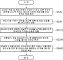
도 10은 본 발명의 다른 하나의 실시 예에 따른 전력량계 시스템의 신호 변환 방법을 개략적으로 나타내는 흐름도이다.
도 11은 본 발명의 하나의 실시 예에 따른 전력량계 시스템의 신호 변환 방법의 일부 공정을 개략적으로 나타내는 흐름도이다.
도 12는 본 발명의 다른 하나의 실시 예에 따른 전력량계 시스템의 신호 변환 방법을 개략적으로 나타내는 흐름도이다.
도 13은 본 발명의 다른 또 하나의 실시 예에 따른 전력량계 시스템의 신호 변환 방법을 개략적으로 나타내는 흐름도이다.1 is a block diagram schematically illustrating an apparatus for converting a signal of a power meter system according to an embodiment of the present invention.
2A and 2B are block diagrams schematically illustrating a signal conversion apparatus of a power meter system according to another embodiment of the present invention.
3 is a block diagram schematically illustrating a power meter system including a signal conversion device of a power meter system according to another embodiment of the present invention.
4 is a block diagram schematically illustrating an apparatus for converting a signal of a power meter system according to another embodiment of the present invention.
5 is a diagram illustrating a signal component and a transition frequency detected by a sensing block according to an embodiment of the present invention.
FIG. 6 is a diagram illustrating a signal component transitioned by a frequency shifting unit in an embodiment of the present invention.
7 is a diagram illustrating signal components coupled by a signal combiner in an embodiment of the present invention.
8 is a diagram showing an output frequency spectrum by a sigma-delta modulator according to an embodiment of the present invention.
9 is a diagram illustrating signal components processed by a frequency down converter and a digital filter in an embodiment of the present invention.
10 is a flowchart schematically illustrating a signal conversion method of a power meter system according to another embodiment of the present invention.
11 is a flowchart schematically illustrating some processes of a signal conversion method of a power meter system according to an embodiment of the present invention.
12 is a flowchart schematically illustrating a signal conversion method of a power meter system according to another embodiment of the present invention.
FIG. 13 is a flowchart schematically illustrating a signal conversion method of a power meter system according to another embodiment of the present invention.
전술한 과제를 달성하기 위한 본 발명의 실시 예들이 첨부된 도면을 참조하여 설명될 것이다. 본 설명에 있어서, 동일부호는 동일한 구성을 의미하고, 당해 분야의 통상의 지식을 가진 자에게 본 발명의 이해를 도모하기 위하여 부차적인 설명은 생략될 수도 있다.Embodiments of the present invention for achieving the above object will be described with reference to the accompanying drawings. In the description, the same reference numerals denote the same components, and a detailed description may be omitted for the sake of understanding of the present invention to those skilled in the art.
본 명세서에서 하나의 구성요소가 다른 구성요소와 연결, 결합 또는 배치 관계에서 '직접'이라는 한정이 없는 이상, '직접 연결, 결합 또는 배치'되는 형태뿐만 아니라 그들 사이에 또 다른 구성요소가 개재됨으로써 연결, 결합 또는 배치되는 형태로도 존재할 수 있다. 또한, '상에', '위에', '하부에', '아래에' 등의 '접촉'의 의미를 내포할 수 있는 용어들이 포함된 경우도 마찬가지이다. 방향을 나타내는 용어들은 기준이 되는 요소가 뒤집어지거나 그의 방향이 바뀌는 경우 그에 따른 대응되는 상대적인 방향 개념을 내포하는 것으로 해석될 수 있다.As used herein, unless an element is referred to as being 'direct' in connection, combination, or placement with other elements, it is to be understood that not only are there forms of being 'directly connected, They may also be present in the form of being connected, bonded or disposed. In addition, the same is true when terms including 'contact' such as 'up', 'up', 'lower', 'below' are included. Directional terms may be construed to encompass corresponding relative directional concepts as the reference element is inverted or its direction is changed.
본 명세서에 비록 단수적 표현이 기재되어 있을지라도, 발명의 개념에 반하거나 명백히 다르거나 모순되게 해석되지 않는 이상 복수의 구성 전체를 대표하는 개념으로 사용될 수 있음에 유의하여야 한다. 본 명세서에서 '포함하는', '갖는', '구비하는', '포함하여 이루어지는' 등의 기재는 하나 또는 그 이상의 다른 구성요소 또는 그들의 조합의 존재 또는 부가 가능성이 있는 것으로 이해되어야 한다.
It should be noted that, even though a singular expression is described in this specification, it can be used as a concept representing the entire plurality of constitutions unless it is contrary to, or obviously different from, or inconsistent with the inventive concept. It is to be understood that the description of 'comprising', 'having', 'comprising', 'comprising', etc., in this specification includes the possibility of the presence or addition of one or more other components or combinations thereof.
우선, 본 발명의 제1 실시 예에 따른 전력량계 시스템의 신호 변환 장치를 도면을 참조하여 구체적으로 살펴본다.First, a signal conversion apparatus of a power meter system according to a first embodiment of the present invention will be described in detail with reference to the accompanying drawings.
도 1은 본 발명의 하나의 실시 예에 따른 전력량계 시스템의 신호 변환 장치를 개략적으로 나타낸 블럭도이고, 도 2a 및 2b는 본 발명의 또 하나의 실시 예에 따른 전력량계 시스템의 신호 변환 장치를 개략적으로 나타낸 블럭도이고, 도 3은 본 발명의 또 하나의 실시 예에 따른 전력량계 시스템의 신호 변환 장치를 포함하는 전력량계 시스템을 개략적으로 나타내는 블럭도이고, 도 4는 본 발명의 또 하나의 실시 예에 따른 전력량계 시스템의 신호 변환 장치를 개략적으로 나타내는 블럭도이다. 도 5는 본 발명의 실시 예에서 센싱블럭에 감지된 신호 성분과 천이주파수를 나타내는 도면이고, 도 6은 본 발명의 실시 예에서 주파수 천이부에 의해 천이된 신호 성분을 나타내는 도면이고, 도 7은 본 발명의 실시 예에서 신호결합부에 의해 결합된 신호 성분을 나타내는 도면이고, 도 8은 본 발명의 실시 예에서 시그마-델타 변조기에 의한 출력 주파수 스펙트럼을 나타내는 도면이고, 도 9는 본 발명의 실시 예에서 주파수 다운 컨버터 및 디지털 필터에 의해 처리되는 신호 성분을 나타내는 도면이다.
1 is a block diagram schematically showing a signal conversion device of a power meter system according to an embodiment of the present invention, Figures 2a and 2b is a schematic diagram of a signal conversion device of a power meter system according to another embodiment of the present invention 3 is a block diagram schematically illustrating a wattmeter system including a signal conversion device of a wattmeter system according to another embodiment of the present invention, and FIG. 4 is a block diagram of another embodiment of the present invention. A block diagram schematically showing a signal conversion device of a watt-hour meter system. FIG. 5 is a diagram illustrating a signal component and a transition frequency detected by a sensing block according to an embodiment of the present invention. FIG. 6 is a diagram illustrating a signal component transitioned by a frequency transition unit according to an embodiment of the present invention. In the embodiment of the present invention is a view showing a signal component coupled by a signal combiner, Figure 8 is a view showing the output frequency spectrum by the sigma-delta modulator in an embodiment of the present invention, Figure 9 is an embodiment of the present invention In the example, the signal components processed by the frequency down converter and the digital filter are shown.
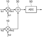
도 1을 참조하면, 본 발명의 제1 실시 예에 따른 전력량계 시스템의 신호 변환 장치는 주파수 천이부(10), 신호결합부(30) 및 아날로그-디지털 변환부(50)를 포함하여 이루어진다.Referring to FIG. 1, a signal conversion device of a watt-hour system according to a first embodiment of the present invention includes a
주파수 천이부(10)는 감지된 전류 및 전압 신호가 서로 다른 주파수 대역을 갖도록 적어도 하나의 신호의 주파수를 천이주파수만큼 천이시킨다. 주파수 천이부(10)에서 전류 및 전압 신호가 서로 다른 주파수 대역을 갖도록 적어도 하나의 신호의 주파수를 천이주파수만큼 천이시켜 중간주파수를 갖도록 함으로써, 주파수 대역의 충돌없이 하나의 신호로 결합할 수 있게 된다. 예컨대, 단상 시스템의 경우 전류 및 전압 신호 중 어느 하나의 신호의 주파수에 대하여 천이주파수만큼 천이시키거나 전류 및 전압 신호 양자의 주파수에 대하여 서로 다른 천이주파수만큼 천이시켜 전류 및 전압 신호가 서로 다른 주파수 대역을 갖도록 할 수 있다. 이때, 감지된 전압 및 전류신호의 기본주파수 신호(~60Hz)는 신호변환 시 요구되는 기준전압을 공급하는 전압 레퍼런스(Voltage Reference) 블럭과 ADC와 같은 신호변환블럭의 DC 오프셋 및 1/f 잡음의 영향으로 열화가 되어, 전력 미터링 시스템의 중요 특성인 정확도의 열화를 야기하게 되므로, 주파수를 천이시킬 필요가 있다. 이때, 천이주파수는 아날로그-디지털 변환 과정에서 저주파대역에서의 DC 오프셋과 1/f 잡음의 영향을 받지 않는 주파수 대역으로 천이시킬 수 있는 주파수일 수 있다.The
또한, 도 1을 참조하면, 하나의 예에서, 주파수 천이부(10)는 감지된 전류 및 전압 신호를 각각 다른 천이주파수만큼 천이시킬 수 있다. 본 실시 예에 따라, 감지된 전류 및 전압 신호 모두에 대하여 각각 다른 천이주파수만큼 천이시킴으로써, 아날로그-디지털 변환 과정에서 저주파대역에서의 DC 오프셋과 1/f 잡음에 의한 아날로그-디지털 컨버팅의 분해능(Resolution) 열화 및 SNR 감소 등을 방지할 수 있다.In addition, referring to FIG. 1, in one example, the
일반적으로 전력선의 신호는 110V나 220V의 세기와 60Hz의 기본주파수의 특성을 가지는데, 이때, 주파수 성분은 전력공급원과 전력 공급선 경로 상의 비선형 특성으로 인하여 고조파(Harmonic) 성분들이 발생하게 된다. 일반적으로 전력량계는 20차 고조파 성분(1.2KHz)까지 분석을 하므로, 주파수 천이된 전압신호와 전류신호의 중간주파수가 예컨대 1.2KHz 이상의 천이 간격을 갖도록 할 수 있다.In general, the power line signal has characteristics of 110V or 220V strength and a fundamental frequency of 60Hz. At this time, harmonic components are generated due to the nonlinear characteristics of the power supply source and the power supply line path. In general, since the wattmeter analyzes up to the 20th harmonic component (1.2KHz), an intermediate frequency of the frequency shifted voltage signal and the current signal may have a transition interval of, for example, 1.2KHz or more.
도 3 및 5를 참조하면, 전류 및 전압 센싱블럭(5, 6)에서 전력선 상의 전류와 전압 신호를 검출한다. 이때, 전류 신호와 전압 신호는 전압 신호의 형태로 검출할 수 있고, 해당 전압신호의 크기는 각각 아날로그-디지털 변환을 위한 입력 범위에 맞추기 위해서 일정한 비율로 센싱블럭에서 감쇄되어 조정된다. 예컨대, 전류신호 센싱블럭(6)은 변류기(CT) 및 션트(Shunt) 저항, 홀 센서(Hall Sensor) 등을 통하여 전압신호로 검출할 수 있다. 전류 및 전압 센싱블럭(5, 6)에서 검출된 전류 신호와 전압신호 결합시 주파수가 중첩되지 않도록 하기 위하여, 주파수 천이부(10)는 전류신호와 전압신호 각각 다른 천이주파수만큼 천이시키거나 전류 및 전압 신호 중 어느 하나의 신호를 천이주파수만큼 천이시킨다.
3 and 5, current and voltage sensing blocks 5 and 6 detect current and voltage signals on power lines. At this time, the current signal and the voltage signal can be detected in the form of a voltage signal, and the magnitude of the corresponding voltage signal is attenuated and adjusted in the sensing block at a constant ratio to match the input range for the analog-digital conversion, respectively. For example, the current
도 1 내지 3을 참조하면, 하나의 예에서, 주파수 천이부(10)는 전류 및 전압 신호가 서로 다른 주파수 대역을 갖도록, 적어도 하나의 신호의 주파수와 천이주파수를 합성하거나 양자 모두의 신호의 주파수와 각각 서로 다른 천이주파수를 합성하여 주파수 천이된 중간주파수를 생성하는 주파수합성기(Frequency Mixer)(10)일 수 있다. 1 to 3, in one example, the
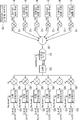
도 5 및 6을 참조하면, 주파수 합성기(10)는 각각의 전압 및 전류의 센싱블럭(5, 6)에 의해 감지된 fo1과 fo2의 기본 주파수(Fundamental Frequency) 성분(DC~2KHz)을 갖는 전압과 전류의 각각의 신호들을 주파수 발생기(Frequency Generator)(70)에 의해 생성된 fc1 및 fc2의 천이주파수를 갖는 신호와 합성하여, fm1 및 fm2의 중간주파수(Intermediate Frequency)에 해당하는 신호를 생성하게 된다. 센싱블럭(5, 6)에 의해 감지된 fo1과 fo2의 기본 주파수 성분은 저주파대역에 존재하므로, 아날로그-디지털 변환 과정에서 저주파대역에서의 DC 오프셋과 1/f 잡음에 의한 영향을 받지 않도록 천이주파수만큼 천이시킬 수 있다. 여기서, fm1은 fo1 + fc1 이고, fm2는 fo2 + fc2 이다. 즉, 예컨대 60Hz의 기본 주파수(f0)를 가진 전압 및 전류 검출 신호는 주파수 합성기(10)에 의해 fc1과 fc2의 천이주파수로 업-컨버젼(Up-conversion)하여, 도 6과 같이 fm1과 fm2의 중간주파수를 가진 전압 및 전류 변환 신호를 생성하게 된다. 도 5에서, fo1은 감지된 전압 신호의 기본 주파수이고, fo2는 감지된 전류신호의 기본 주파수이다. 이때, 기본 주파수는 예컨대 50 또는 60Hz 대역의 동일주파수이므로, 각각 다른 천이주파수를 가지고 천이시킬 필요가 있다. 주파수 대역을 달리하도록 하기 위해, 전압신호에 대한 천이주파수 fc1, 예컨대 1KHz 주파수와 전류신호에 대한 천이주파수 fc2, 예컨대 2KHz 주파수를 각각 기본주파수와 합성하여, 도 6에 도시된 바와 같이, 전압신호에 대한 중간주파수 fm1, 예컨대 1.06KHz 주파수와 전류신호에 대한 중간주파수 fm2, 예컨대 2.06KHz 주파수로 주파수를 변환시킨다. 도 6에서 전압신호에 대한 중간주파수 fm1과 전류신호에 대한 중간주파수 fm2는 주파수 대역을 달리하므로 하나의 신호로 결합할 수 있게 된다. 이때, 기본주파수 fo1와 fo2를 가지고 설명하였으나, 센싱된 전압신호 및 전류신호에 기본주파수 외에 고조파 성분들도 포함될 수 있고, 이러한 고조파 성분들도 마찬가지로 일체로 주파수 천이되고, 함께 하나의 신호로 결합될 수 있다. 또한, 천이주파수 fc1의 1KHz와 천이주파수 fc2의 2KHz는 발명의 이해를 돕기 위해 예시되는 것으로 발명의 범위를 한정하지 않는다.
5 and 6, the
본 실시 예에 따른 주파수 컨버전을 통하여 각각의 주파수 대역에서 아날로그-디지털 변환을 수행하므로, 서로 다른 주파수 대역이나 서로 다른 상간의 간섭을 최소화할 수 있다.
Since the analog-to-digital conversion is performed in each frequency band through frequency conversion according to the present embodiment, interference between different frequency bands or different phases can be minimized.
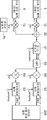
하나의 예에서, 전류 및 전압 신호는 단상일 수도 있으며, 또는 도 4에 도시된 바와 같이 3상 신호일 수도 있다. 3상 시스템의 경우, 주파수 천이부(10)는 3상의 전압 및 전류 신호 각각이 서로 다른 주파수 대역을 갖도록 주파수를 천이시킨다. 이때, 도 4에 도시된 바와 같이 3상의 전압 및 전류 신호 모두를 각각 다른 천이주파수만큼 천이시키거나 또는, 도시되지 않았으나, 3상의 전압 및 전류 신호 중 어느 하나를 제외하고 나머지 신호를 각각 다른 천이주파수만큼 천이시킴으로써 3상의 전압 및 전류 신호 모두가 서로 다른 주파수 대역을 갖도록 할 수 있다.In one example, the current and voltage signals may be single phase, or may be three phase signals as shown in FIG. In the three-phase system, the
3상 신호인 경우, 주파수 합성기(10)는 각 상마다 필요하므로, 예컨대 6개 또는 3상 4선식의 경우 7개의 주파수 합성기(10)가 요구될 수 있다. 또는, 3상의 전압 및 전류 신호 중 어느 하나를 제외하고 나머지 신호를 각각 다른 천이주파수만큼 천이시키는 경우에는 5개의 주파수 합성기(10)만이 구비될 수도 있다. 도 4를 참조하면, 3상 신호인 경우를 나타내고 있는데, 주파수 합성기(10)가 예컨대 6개가 도시되어 있다.
In the case of a three-phase signal, since the
도 1에서, 신호결합부(30)는 서로 다른 주파수 대역을 갖는 전류 및 전압 신호를 하나의 신호로 결합한다.In FIG. 1, the
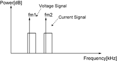
또한, 도 1 내지 3을 참조하면, 하나의 예에서, 신호결합기(30)는 전력 결합기(Power Combiner)(30)일 수 있다. 도 1에서, 예컨대, 주파수 천이된 전압신호 중간주파수 fm1과 주파수 천이된 전류신호 중간주파수 fm2가 전력 결합기(30)에 의해 하나의 신호로 결합된다. 도 4를 참조하면, 3상 신호의 경우 예컨대 6개의 주파수 합성기(10)로부터 각각 다른 주파수로 천이된 6개의 주파수 신호가 하나의 전력 결합기(30)에서 각각 주파수대역을 달리하는 하나의 신호로 결합될 수 있다. 도 7을 참조하면, 전력 결합기(30)는 주파수 천이된 전압신호 중간주파수 fm1과 주파수 천이된 전류신호 중간주파수 fm2의 주파수 스펙트럼을 갖는 하나의 신호를 생성하게 된다.
1 to 3, in one example, the
다음으로, 도 1에서, 아날로그-디지털 변환부(50)는 하나의 신호로 결합된 아날로그신호를 디지털신호로 변환한다. 아날로그-디지털 변환부(50)는 아날로그-디지털 컨버터(ADC)와 필터로 이루어질 수 있다. 아날로그-디지털 컨버터는 결합된 하나의 아날로그신호를 디지털 신호로 변환하고, 변환된 디지털 신호는 노이즈 제거와 필요한 주파수 대역 신호만을 얻기 위해서 필터를 통과하게 된다. 일반적으로 전력량계를 위한 아날로그-디지털 변환기는 15비트 이상의 분해능을 가지고 있다. Next, in FIG. 1, the analog-to-
일반적으로 전력선의 신호는 110V나 220V의 세기와 60Hz의 주파수의 특성을 가지는데, 이때, 주파수 성분은 전력공급원과 전력 공급선 경로상의 비선형 특성으로 인하여 고조파(Harmonic) 성분들이 발생하게 된다. 일반적으로 전력량계는 20차 고조파 성분(1.2KHz)까지 분석을 하므로, 아날로그-디지털 변환부(50)는 신호결합부(30)에 결합된 하나의 신호에 포함된 주파수 천이된 전류 및 전압의 기본주파수 신호와 고조파 성분들로 이루어진 아날로그 신호를 디지털 신호로 변환하기 위해서는 특정한 샘플링 주파수(fSampling, Sampling Frequency)를 가지는 N 비트(bit)의 디지털 신호로 출력되게 된다. 이때, 높은 정확도와 높은 감도 등의 특성을 얻기 위해서 시그마-델타(Sigma-Delta, Σ-Δ) 방식을 사용할 수 있다. 시그마-델타 방식은 변조(Modulation)를 위한 시그마-델타 변조기(51)와 복조(Demodulation)를 위한 데시메이션 필터(Decimation Filter)(53) 부분으로 이루어진다.
In general, power line signals have characteristics of 110V or 220V strength and frequency of 60Hz. At this time, harmonic components are generated due to the nonlinear characteristics of the power supply source and the power supply line path. In general, since the wattmeter analyzes up to the 20th harmonic component (1.2KHz), the analog-to-
본 실시 예에 따라, 예컨대, 단상 및 3상 전력 시스템에서 2개 또는 6개의 전압과 전류 신호들을 하나의 아날로그-디지털 변환기(50)를 통하여 변환할 수 있으므로, 전력 소모 및 시스템의 크기를 감소시킬 수 있다.
According to the present embodiment, for example, two or six voltage and current signals may be converted through one analog-to-
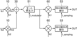
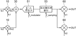
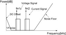
또한, 하나의 예에서, 아날로그-디지털 변환부(50)는 시그마-델타 변조기(51) 및 디지털필터(53)를 포함할 수 있다. 이때, 시그마-델타 변조기(51)는 하나의 신호로 결합된 아날로그신호를 시그마-델타 방식으로 변조하여 디지털신호로 변환시킨다. 디지털필터(53)는 변환된 디지털신호로부터 다운 샘플링하여 원하는 디지털 데이터 신호로 변환시킨다. 도 8을 참조하면, 주파수 천이된 전압신호 중간주파수 fm1과 주파수 천이된 전류신호 중간주파수 fm2 대역을 갖는 하나의 신호에 대한 시그마-델타 변조기(51)의 출력 주파수 스펙트럼이 도시되어 있다. 이때, 저주파대역에 DC 오프셋과 1/f 노이즈가 형성되고, 고유의 노이즈 전달함수(Noise Transfer Function)에 의해 저주파 대역 대비 고주파수 대역에서 높은 노이즈 주파수 스펙트럼을 생성한다.In addition, in one example, the analog-to-
이때, 도 2a, 2b, 3 및 4를 참조하면, 하나의 예에서, 디지털필터(53)는 데시메이션필터일 수 있다. 데시메이션 필터(53)는 변환된 디지털신호로부터 저주파통과 대역 필터링 및 다운 샘플링으로 원하는 N비트 디지털 데이터 신호로 변환시킬 수 있다.2A, 2B, 3, and 4, in one example, the
여기서 데시메이션 필터(53)는 CIC 및 Sinc, Half-Band 등의 필터들을 포함하여 이루어질 수 있다. 데시메이션 필터(53)는 도 8에 도시된 시그마-델타 변조기(51)의 NTF(Noise Transfer Function)에 의한 높은 주파수대역의 잡음을 제거할 수 있다. 또한, 데시메이션 필터(53)는 OSR(Over Sampling Ratio)에 맞는 샘플링 레이트의 출력 데이터를 생성하게 된다.
Here, the
구체적으로 설명하면, 신호결합부(30)에 결합된 하나의 신호에 포함된 주파수 천이된 전류 및 전압의 기본주파수 신호와 고조파 성분들로 이루어진 아날로그 신호가 시그마-델타 변조기(51)에 입력된다. 이때, 시그마-델타 변조기(51)는 오버 샘플링주파수(Over Sampling Frequency, fM)의 주기로 샘플링 및 변조하여 1비트의 디지털 신호로 변환할 수 있다. 실제 신호주파수보다 오버샘플링된 1bit의 변조 신호는 데시메이션 필터(53)에서 복조되어 원하는 샘플링 주파수(Sampling Frequency, fSampling)로 복원되게 된다. 이때, 오버 샘플링 주파수는 수 MHz 대역이며 샘플링 주파수는 대략 2KHz ~ 10KHz 대역을 가질 수 있다. 일반적으로 샘플링 주파수는 60Hz의 기본 주파수 성분과 1차~20차 고조파 성분(120Hz ~ 1.2KHz)를 포함한 주파수 대역(fBW)의 신호의 2배수인 2.4KHz 이상을 가질 수 있는데, 본 발명의 실시 예에서는 신호 결합부에서 주파수 천이된 전류 및 전압 신호가 하나의 신호에 포함되어 있으므로, 천이주파수를 고려하여 샘플링 주파수를 결정할 수 있다. 예컨대,
Specifically, an analog signal composed of fundamental frequency signals and harmonic components of frequency shifted current and voltage included in one signal coupled to the
또한, 도 3을 참조하면, 하나의 예에서, 아날로그-디지털 변환부(50)는 시그마-델타 변조기(51)에서 변환된 디지털신호로부터 저주파대역의 DC 오프셋과 1/f 노이즈 성분을 제거하여 출력하는 대역통과필터(55)를 더 포함할 수 있다. 이때, 대역통과필터(55)는 하이패스필터(HPF)(55) 또는 밴드패스필터(BPF)일 수 있다. 도 8에서 저주파대역에 형성된 DC 오프셋과 1/f 노이즈는 하이패스필터(HPF)(55) 또는 밴드패스필터(BPF)를 통과하며 제거될 수 있다. 도 2a 및 2b에 도시되지 않았으나, 시그마-델타 변조기(51) 다음에 대역통과필터(55)가 구비될 수 있다.In addition, referring to FIG. 3, in one example, the analog-to-
본 실시 예에 따라, 시그마-델타 변조기(51)에 의한 DC 오프셋과 1/f 잡음의 영향을 받지 않고, 더 높은 SNR을 갖는 신호의 샘플링이 가능하다.
According to the present embodiment, sampling of a signal having a higher SNR is possible without being affected by the DC offset and 1 / f noise by the sigma-
또한, 도 2a 및 2b를 참조하여 하나의 예를 살펴보면, 전력량계 시스템의 신호 변환 장치는 주파수 다운 컨버터(60)를 더 포함할 수 있다.Also, referring to FIGS. 2A and 2B, a signal conversion device of a watt-hour system may further include a frequency down
도 2a를 참조하면, 주파수 다운 컨버터(60)는 시그마-델타 변조기(51)에서 변환된 디지털신호로부터 천이주파수만큼 하향 천이시켜 전류 및 전압 신호에 해당하는 신호로 복원한다. 이때, 주파수 다운 컨버터(60)는 주파수 천이된 전류 또는 전압 신호에 대해서 천이주파수만큼 하향 천이시켜 전류 또는 전압 신호를 복원할 수 있다. 이때, 도시되지 않았으나, 하나의 예에서, 해당 주파수별로 시간 분할 처리를 위하여 멀티플렉서가 주파수 다운 컨버터(60) 앞 단에 삽입될 수도 있다.Referring to FIG. 2A, the frequency down
이때, 도 2a를 참조하면, 디지털필터(53)는 주파수 다운 컨버터(60)에서 복원된 전류 및 전압 신호로부터 다운 샘플링하여 원하는 디지털 데이터 신호로 변환할 수 있다. 만일, 주파수가 천이되지 않은 신호가 있는 경우에는 주파수 다운 컨버터(60)에서 천이주파수만큼 하향 천이시키는 과정을 거치지 않고 분리되어 디지털필터(53)로 입력되는 경우 직접 디지털필터(53)에서 다운 샘플링하여 원하는 디지털 데이터 신호로 변환될 수 있다.In this case, referring to FIG. 2A, the
주파수 다운 컨버터(60)는 예컨대, 하이패스필터에 의한 전압 신호 및 전류 신호를 각각의 천이주파수(fc1 및 fc2)만큼 주파수를 하향 천이시켜, fo1의 주파수의 전압 신호와 fo2의 주파수의 전류 신호를 각각 분리하여 생성하게 된다. 전력 결합기(30)에서 하나의 신호로 결합된 신호는 각각의 주파수 다운 컨버터(60)에 의하여, 전압 및 전류 신호로 복원된다. 이때, 예컨대 데시메이션 필터(53)는 저주파통과 대역 필터링 및 다운 샘플링으로 원하는 N비트 디지털 데이터 신호로 변환시킬 수 있다.The frequency down
또한, 도 2b를 참조하면, 다른 하나의 예에서, 주파수 다운 컨버터(60)와 디지털필터(53)의 순서를 바꾸어 처리할 수 있다. 즉, 주파수 다운 컨버터(60)는 디지털필터(53)에서 변환된 디지털 데이터 신호로부터 천이주파수만큼 하향 천이시켜 전류 및 전압 신호를 복원할 수 있다. 이때, 주파수 다운 컨버터(60)는 주파수 천이된 전류 또는 전압 신호에 대해서 천이주파수만큼 하향 천이시켜 전류 또는 전압 신호를 복원할 수 있다. 도시되지 않았으나, 하나의 예에서, 해당 주파수별로 시간 분할 처리를 위하여 멀티플렉서가 주파수 다운 컨버터(60) 앞 단에 삽입될 수도 있다.In addition, referring to FIG. 2B, in another example, the order of the frequency down
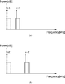
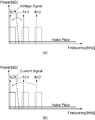
도 9를 참조하면, 주파수 다운 컨버터(60) 및 데시메이션 필터(53)에 의해 전압 및 전류 신호에 해당하는 신호가 처리되는 것이 도시되어 있고, 도 9의 (a)는 전압신호에 해당하는 신호가 주파수 다운 컨버터(60)에서 천이주파수만큼 하향 천이되고 데시메이션 필터(53)에서 저주파통과 대역 필터링 및 다운 샘플링으로 원하는 N비트 디지털 데이터 신호로 변환되는 것을 도시하고, 도 9의 (b)는 전류신호에 해당하는 신호가 주파수 다운 컨버터(60)에서 천이주파수만큼 하향 천이되고 데시메이션 필터(53)에서 저주파통과 대역 필터링 및 다운 샘플링으로 원하는 N비트 디지털 데이터 신호로 변환되는 것을 도시하고 있다. 데시메이션 필터(53)는 통과 주파수 대역이 전압신호(fm1)와 전류신호(fm2)의 주파수보다 높기 때문에 전압신호(fm1)와 전류신호(fm2)를 모두 처리할 수 있다.
9, a signal corresponding to a voltage and a current signal is processed by the frequency down
본 실시 예는 도 4에 도시된 바와 같이, 3상의 전력 미터링 시스템에 적용될 수 있다. 예컨대, 3쌍의 전력 및 전류 신호는 각각의 중간주파수(IF)로 천이 되어 복원되므로, 하나의 아날로그-디지털 컨버터(50)에 의하여 신호를 변환할 수 있다.This embodiment can be applied to a three-phase power metering system, as shown in FIG. For example, since the three pairs of power and current signals are shifted and restored to respective intermediate frequencies IF, the signal may be converted by one analog-to-
단상 및 3상 전력 시스템에서 2개 또는 6개의 전압과 전류 신호들을 하나의 아날로그-디지털 변환기(50)를 통하여 변환하므로, 전력 소모 및 시스템의 크기를 감소 시킬 수 있다.In single-phase and three-phase power systems, two or six voltage and current signals are converted through one analog-to-
본 실시 예에 따른 전력량계 시스템의 신호 변환 장치는 통합회로(Integrate circuit) 또는 시스템-온-칩(System-on-chip)으로 구현될 수 있다.
The signal conversion device of the electricity meter system according to the present embodiment may be implemented as an integrated circuit or a system-on-chip.
다음으로, 본 발명의 제2 실시 예에 따른 전력량계 시스템을 도면을 참조하여 구체적으로 살펴본다. 본 실시 예를 설명함에 있어서, 다음의 도 3뿐만 아니라 전술한 제1 실시 예에 따른 전력량계 시스템의 신호 변환 장치 및 도 1, 2, 4 내지 9가 참조될 것이고, 그에 따라 중복되는 설명들은 생략될 수 있다.Next, a power meter system according to a second embodiment of the present invention will be described in detail with reference to the accompanying drawings. In the following description of the present embodiment, reference will be made to the signal conversion device of the electricity meter system according to the first embodiment and FIGS. 1, 2, 4 to 9 as well as the following FIG. 3, and thus redundant descriptions will be omitted. Can be.
도 3은 본 발명의 또 하나의 실시 예에 따른 전력량계 시스템의 신호 변환 장치를 포함하는 전력량계 시스템을 개략적으로 나타내는 블럭도이다.
3 is a block diagram schematically illustrating a power meter system including a signal conversion device of a power meter system according to another embodiment of the present invention.
도 3을 참조하면, 본 발명의 제2 실시 예에 따른 전력량계 시스템은 전류 및 전압 센싱블럭(5, 6), 신호 변환 장치 및 디지털 처리블럭(200)을 포함하여 이루어질 수 있다. 디지털 처리블럭(200)이 도 3에만 도시되었으나, 도 1, 2a, 2b, 4에도 마찬가지로 구비될 수 있다. Referring to FIG. 3, the electricity meter system according to the second embodiment of the present invention may include a current and voltage sensing blocks 5 and 6, a signal converter, and a
전류 및 전압 센싱블럭(5, 6)은 전류 및 전압 신호를 감지한다. 즉, 전력선의 전압과 전류는 각각의 센서들을 통해 감지하여 각각의 해당 크기의 전압 신호들로 출력할 수 있다. 예컨대, 전류 및 전압 센싱블럭(5, 6)은 전류신호 부분을 감지하기 위한 변류기(Current Transformer)와 전압신호 부분을 감지하기 위한 전압 분배기(Voltage Divider)로 구성될 수 있다. 변류기(Current Transformer)와 전압 분배기(Voltage Divider)는 센싱되는 전력선의 전압과 전류를 예컨대 수천분의 1로 감쇄하고, 감쇄된 크기 만큼의 전압 신호로 출력하게 된다.The current and voltage sensing blocks 5 and 6 sense current and voltage signals. That is, the voltage and the current of the power line may be sensed through the respective sensors and output as voltage signals of respective corresponding magnitudes. For example, the current and voltage sensing blocks 5 and 6 may include a current transformer for sensing a current signal portion and a voltage divider for sensing a voltage signal portion. Current transformers and voltage dividers attenuate the voltage and current of the sensed power line, for example, by a thousandths, and output the voltage signal as much as the attenuated magnitude.
이때, 단상의 전류 및 전압 신호를 센싱할 수도 있고, 도 4에 도시된 바와 같이 3상의 전류 및 전압 신호를 센싱할 수도 있다.
In this case, the single-phase current and voltage signals may be sensed, or the three-phase current and voltage signals may be sensed as shown in FIG. 4.
다음으로, 전력량계 시스템의 신호 변환 장치는 전류 및 전압 센싱블럭(5, 6)에서 감지된 신호를 디지털신호로 변환 처리한다. 이때, 전력량계 시스템의 신호 변환 장치는 전술한 제1 실시 예들 중의 어느 하나에 따른 신호 변환 장치일 수 있다. Next, the signal conversion device of the electricity meter system converts the signals sensed by the current and voltage sensing blocks 5 and 6 into digital signals. In this case, the signal conversion device of the electricity meter system may be a signal conversion device according to any one of the above-described first embodiments.
도 2a를 참조하면, 하나의 예에서, 신호 변환 장치는 시그마-델타 변조기(51)에서 변환된 디지털신호로부터 천이주파수만큼 하향 천이시켜 전류 및 전압 신호에 해당하는 신호로 복원하는 주파수 다운 컨버터(60)를 더 포함할 수 있다. 이때, 주파수 다운 컨버터(60)는 주파수 천이된 전류 또는 전압 신호에 대해서 천이주파수만큼 하향 천이시켜 전류 또는 전압 신호를 복원할 수 있다.Referring to FIG. 2A, in one example, the signal converter converts the digital signal converted by the sigma-
나아가, 이때, 도 2a를 참조하면, 디지털필터(53)는 주파수 다운 컨버터(60)에서 복원된 전류 및 전압 신호로부터 다운 샘플링하여 원하는 디지털 데이터 신호로 변환할 수 있다.In addition, referring to FIG. 2A, the
또한, 도 2b를 참조하면, 다른 하나의 예에서, 신호 변환 장치는 변환된 디지털 데이터 신호로부터 천이주파수만큼 하향 천이시켜 전류 및 전압 신호를 복원하는 주파수 다운 컨버터(60)를 더 포함할 수 있다. 이때, 주파수 다운 컨버터(60)는 주파수 천이된 전류 또는 전압 신호에 대해서 천이주파수만큼 하향 천이시켜 전류 또는 전압 신호를 복원할 수 있다.Also, referring to FIG. 2B, in another example, the signal conversion apparatus may further include a frequency down
추가적인 설명은 전술한 제1 실시 예들을 참조하도록 한다.For further description, refer to the first embodiment described above.
다음으로, 디지털 처리블럭(200)은 신호 변환 장치에서 출력되는 디지털 데이터 값으로부터 전력량을 산출한다. 디지털 처리블럭(200)은 전력량계에서 요구하는 유효 전력량(Active Power), 무효 전력량(Reactive Power), 역률(Power Factor) 등을 계산하고, 디지털 회로에 의한 적분기, 곱셈기, 필터 등으로 구성될 수 있다.
Next, the
본 실시 예에 따른 전력량계 시스템은 통합회로(Integrate circuit) 또는 시스템-온-칩(System-on-chip)으로 구현할 수 있다.
The electricity meter system according to the present embodiment may be implemented as an integrated circuit or a system-on-chip.
다음으로, 본 발명의 제3 실시 예에 따른 전력량계 시스템의 신호 변환 방법을 도면을 참조하여 구체적으로 살펴본다. 본 실시 예를 설명함에 있어서, 다음의 도 10 내지 13뿐만 아니라 전술한 제1 실시 예에 따른 전력량계 시스템의 신호 변환 장치 및 도 1 내지 9가 참조될 것이고, 그에 따라 중복되는 설명들은 생략될 수 있다.Next, a signal conversion method of the electricity meter system according to the third embodiment of the present invention will be described in detail with reference to the accompanying drawings. In the following description of the present embodiment, reference will be made to the signal conversion device of the wattmeter system according to the first embodiment described above and FIGS. 1 to 9 as well as the following FIGS. 10 to 13, and thus redundant descriptions may be omitted. .
도 10은 본 발명의 다른 하나의 실시 예에 따른 전력량계 시스템의 신호 변환 방법을 개략적으로 나타내는 흐름도이고, 도 11은 본 발명의 하나의 실시 예에 따른 전력량계 시스템의 신호 변환 방법의 일부 공정을 개략적으로 나타내는 흐름도이고, 도 12는 본 발명의 다른 하나의 실시 예에 따른 전력량계 시스템의 신호 변환 방법을 개략적으로 나타내는 흐름도이고, 도 13은 본 발명의 다른 또 하나의 실시 예에 따른 전력량계 시스템의 신호 변환 방법을 개략적으로 나타내는 흐름도이다.
FIG. 10 is a flowchart schematically illustrating a signal conversion method of a power meter system according to another embodiment of the present invention, and FIG. 11 is a schematic diagram illustrating a part of a signal conversion method of a power meter system according to an embodiment of the present invention. 12 is a flowchart schematically illustrating a signal conversion method of a power meter system according to another embodiment of the present invention, and FIG. 13 is a signal conversion method of a power meter system according to another embodiment of the present invention. It is a flowchart which shows schematically.
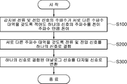
도 10을 참조하면, 본 발명의 제3 실시 예에 따른 전력량계 시스템의 신호 변환 방법은 주파수를 천이시키는 단계(S100), 하나의 신호로 결합하는 단계(S200) 및 아날로그-디지털 변환 단계(S300)를 포함하여 이루어진다. 또한, 도 12 및 13을 참조하면, 전력량계 시스템의 신호 변환 방법은 주파수 다운 컨버팅 단계(S400)를 더 포함할 수 있다.Referring to FIG. 10, in the signal conversion method of the watt-hour meter system according to the third embodiment of the present invention, a step of shifting frequencies (S100), a step of combining them into one signal (S200), and an analog-digital conversion step (S300) It is made, including. 12 and 13, the signal conversion method of the electricity meter system may further include a frequency down converting step (S400).
도 10의 주파수를 천이시키는 단계(S100)에서는 감지된 전류 및 전압 신호가 서로 다른 주파수 대역을 갖도록 적어도 하나의 신호의 주파수를 천이주파수만큼 천이시킨다. 주파수를 천이시키는 단계(S100)에서는 전류 및 전압 신호가 서로 다른 주파수 대역을 갖도록 함으로써, 충돌없이 하나의 신호로 결합할 수 있게 된다. 예컨대, 단상 시스템의 경우 전류 및 전압 신호 중 어느 하나의 신호의 주파수에 대하여 천이주파수만큼 천이시키거나 전류 및 전압 신호 양자의 주파수에 대하여 서로 다른 천이주파수만큼 천이시켜 전류 및 전압 신호가 서로 다른 주파수 대역을 갖도록 할 수 있다. In the step of shifting the frequency of FIG. 10, the frequency of the at least one signal is shifted by the transition frequency so that the sensed current and voltage signals have different frequency bands. In the step of shifting the frequency (S100), the current and voltage signals have different frequency bands, thereby combining them into one signal without collision. For example, in the case of a single-phase system, a frequency band in which the current and voltage signals are different from each other by shifting the frequency of one of the current and voltage signals by a transition frequency or by a different transition frequency with respect to the frequency of the current and voltage signals. It can be to have.
이때, 하나의 예에서, 주파수를 천이시키는 단계(S100)에서 감지된 전류 및 전압 신호를 각각 다른 천이주파수만큼 천이시킬 수 있다. 본 실시 예에 따라, 감지된 전류 및 전압 신호 모두에 대하여 각각 다른 천이주파수만큼 천이시킴으로써, 저주파대역에서의 DC 오프셋과 1/f 잡음에 의한 아날로그-디지털 컨버팅의 분해능(Resolution) 열화 및 SNR 감소 등을 방지할 수 있다.In this case, in one example, the current and voltage signals sensed in the step of shifting the frequency may be shifted by different transition frequencies. According to the present embodiment, by shifting each of the sensed current and voltage signals by different transition frequencies, resolution degradation and SNR reduction of analog-to-digital conversion due to DC offset and 1 / f noise in the low frequency band are performed. Can be prevented.
또 하나의 예에서, 전류 및 전압 신호는 단상일 수도 있고, 또는 도 4에 도시된 바와 같이 3상 신호일 수도 있다.
In another example, the current and voltage signals may be single phase or three phase signals as shown in FIG. 4.
다음, 도 10의 하나의 신호로 결합하는 단계(S200)에서는 서로 다른 주파수 대역을 갖는 전류 및 전압 신호를 하나의 신호로 결합한다.
Next, in the step S200 of combining one signal of FIG. 10, current and voltage signals having different frequency bands are combined into one signal.
다음으로, 도 10의 아날로그-디지털 변환 단계(S300)에서는 하나의 신호로 결합된 아날로그신호를 디지털신호로 변환한다.Next, in the analog-to-digital conversion step (S300) of FIG. 10, the analog signal combined into one signal is converted into a digital signal.
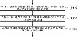
또한, 하나의 예에서, 아날로그-디지털 변환 단계(S300)는 시그마-델타 변조 단계(S310, S2310) 및 디지털 데이터 신호로 변환하는 단계(S330, S1330, S2330)를 포함할 수 있다. 이때, 시그마-델타 변조 단계(S310, S2310)에서는 하나의 신호로 결합된 아날로그신호를 시그마-델타 변조 방식으로 디지털신호로 변환한다. 또한, 디지털 데이터 신호로 변환하는 단계(S330, S1330, S2330)에서는 시그마-델타 변조 단계(S310, S2310)에서 변환된 디지털신호로부터 디지털필터(53)를 이용하여 다운 샘플링하여 원하는 디지털 데이터 신호로 변환할 수 있다.
Also, in one example, the analog-to-digital conversion step S300 may include sigma-delta modulation steps S310 and S2310 and converting them into digital data signals S330, S1330 and S2330. At this time, the sigma-delta modulation step (S310, S2310) converts the analog signal combined into one signal into a digital signal by the sigma-delta modulation method. In addition, in steps S330, S1330, and S2330, the digital signals are down-sampled from the digital signals converted in the sigma-delta modulation steps S310 and S2310 using the
또한, 도 2a, 2b, 3 및 4를 참조하면, 하나의 예에서, 디지털필터(53)는 데시메이션필터(53)일 수 있다. 디지털 데이터 신호로 변환하는 단계(S330, S1330, S2330)에서는 변환된 디지털신호로부터 데시메이션필터(53)를 이용하여 저주파통과 대역 필터링 및 다운 샘플링으로 원하는 N비트 디지털 데이터 신호로 변환할 수 있다.2A, 2B, 3, and 4, in one example, the
또한, 도 11을 참조하여, 하나의 예를 살펴보면, 아날로그-디지털 변환 단계(S300)는 시그마-델타 변조 단계(S310)에서 변환된 디지털신호로부터 대역통과필터를 사용하여 저주파대역의 DC 오프셋과 1/f 노이즈 성분을 제거하여 출력하는 단계(S320)를 더 포함할 수 있다. 이때, 대역통과필터는 하이패스필터(HPF) 또는 밴드패스필터(BPF)일 수 있다. In addition, referring to FIG. 11, referring to one example, the analog-to-digital conversion step S300 is performed by using a bandpass filter from a digital signal converted in the sigma-delta modulation step S310 and a DC offset of 1 at low frequency band. / f may further include removing and outputting a noise component (S320). In this case, the band pass filter may be a high pass filter (HPF) or a band pass filter (BPF).
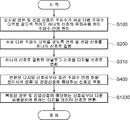
게다가, 도 12 및/또는 13을 참조하여 하나의 예를 살펴보면, 전력량계 시스템의 신호 변환 방법은 주파수 다운 컨버팅 단계(S400, S2400)를 더 포함할 수 있다.In addition, referring to one example with reference to FIGS. 12 and / or 13, the signal conversion method of the electricity meter system may further include frequency down-converting steps S400 and S2400.
먼저, 도 12를 참조하면, 주파수 다운 컨버팅 단계(S400)에서는 시그마-델타 변조 단계(S310)에서 변환된 디지털신호로부터 천이주파수만큼 하향 천이시켜 전류 및 전압 신호에 해당하는 신호로 복원할 수 있다. 이때, 주파수 다운 컨버팅 단계(S400)에서는 주파수 천이된 전류 또는 전압 신호에 대해서 천이주파수만큼 하향 천이시켜 전류 또는 전압 신호를 복원할 수 있다.First, referring to FIG. 12, in the frequency down-converting step S400, the digital signal converted in the sigma-delta modulation step S310 may be shifted downward by a transition frequency to restore a signal corresponding to the current and voltage signals. In this case, in the frequency down-converting step (S400), the current or voltage signal may be restored by shifting down the frequency-shifted current or voltage signal by a transition frequency.
게다가, 도 12를 참조하면, 이때, 디지털 데이터 신호로 변환하는 단계(S1330)에서 디지털필터(53)는 주파수 다운 컨버팅 단계(S400)에서 복원된 전류 및 전압 신호로부터 다운 샘플링하여 원하는 디지털 데이터 신호로 변환할 수 있다.In addition, referring to FIG. 12, in operation S1330, the
또한, 도 13을 참조하면, 다른 하나의 예에서, 주파수 다운 컨버팅 단계(S2400)에서는 디지털 데이터 신호로 변환하는 단계(S2330)에서 변환된 디지털 데이터 신호로부터 천이주파수만큼 하향 천이시켜 전류 및 전압 신호를 복원할 수 있다. 이때, 주파수 다운 컨버팅 단계(S2400)에서는 주파수 천이된 전류 또는 전압 신호에 대해서 천이주파수만큼 하향 천이시켜 전류 또는 전압 신호를 복원할 수 있다.
Further, referring to FIG. 13, in another example, in the frequency down converting step (S2400), the current and voltage signals are shifted downward by the transition frequency from the converted digital data signal in the step (S2330). Can be restored In this case, in the frequency down-converting step (S2400), the current or voltage signal may be restored by shifting down the frequency-shifted current or voltage signal by a transition frequency.
이상에서, 전술한 실시 예 및 첨부된 도면들은 본 발명의 범주를 제한하는 것이 아니라 본 발명에 대한 당해 기술분야에서 통상의 지식을 가진 자의 이해를 돕기 위해 예시적으로 설명된 것이다. 또한, 전술한 구성들의 다양한 조합에 따른 실시 예들이 앞선 구체적인 설명들로부터 당업자에게 자명하게 구현될 수 있다. 따라서, 본 발명의 다양한 실시 예는 본 발명의 본질적인 특성에서 벗어나지 않는 범위에서 변형된 형태로 구현될 수 있고, 본 발명의 범위는 특허청구범위에 기재된 발명에 따라 해석되어야 하며, 당해 기술분야에서 통상의 지식을 가진 자에 의한 다양한 변경, 대안, 균등물들을 포함하고 있다.
In the foregoing description, the above-described embodiments and the accompanying drawings are not limited to the scope of the present invention, but are provided by way of example to help those skilled in the art to understand the present invention. In addition, embodiments according to various combinations of the above-described configurations may be apparent to those skilled in the art from the foregoing detailed description. Accordingly, various embodiments of the invention can be implemented in a modified form without departing from the essential characteristics of the invention, the scope of the invention should be construed in accordance with the invention described in the claims, and It includes various modifications, alternatives, and equivalents by those skilled in the art.
5 : 전압신호 센싱블럭 6 : 전류신호 센싱블럭
10 : 주파수 천이부 또는 주파수 합성기
30 : 신호결합부 또는 전력 결합기
50 : 아날로그-디지털 변환부 51 : 시그마-델타 변조기
53 : 디지털필터 또는 데시메이션필터 55 : 하이패스필터(HPF)
60 : 주파수 다운 컨버터 70 : 주파수 발생기
200 : 디지털 처리블럭5: voltage signal sensing block 6: current signal sensing block
10: frequency shifter or frequency synthesizer
30: signal combiner or power combiner
50: analog-to-digital converter 51: sigma-delta modulator
53 digital filter or
60: frequency down converter 70: frequency generator
200: digital processing block
Claims (20)
상기 서로 다른 주파수 대역을 갖는 전류 및 전압 신호를 하나의 신호로 결합하는 신호결합부; 및
상기 하나의 신호로 결합된 아날로그신호를 디지털신호로 변환하는 아날로그-디지털 변환부; 를 포함하여 이루어지는 전력량계 시스템의 신호 변환 장치.
A frequency shifter for shifting the frequency of at least one signal by a transition frequency such that the sensed current and voltage signals have different frequency bands;
A signal combiner configured to combine the current and voltage signals having different frequency bands into one signal; And
An analog-digital converter for converting the analog signal combined into the one signal; Signal conversion device of the electricity meter system comprising a.
상기 주파수 천이부는 상기 감지된 전류 및 전압 신호를 각각 다른 천이주파수만큼 천이시키는,
전력량계 시스템의 신호 변환 장치.
The method according to claim 1,
The frequency shifting unit shifts the sensed current and voltage signals by different transition frequencies, respectively.
Signal conversion device in the electricity meter system.
상기 전류 및 전압 신호는 3상 신호인,
전력량계 시스템의 신호 변환 장치.
The method according to claim 1,
The current and voltage signals are three-phase signals,
Signal conversion device in the electricity meter system.
상기 주파수 천이부는 상기 전류 및 전압 신호가 서로 다른 주파수 대역을 갖도록 양자 모두의 신호의 주파수와 각각 서로 다른 천이주파수를 합성하여 주파수 천이된 중간주파수를 생성하는 주파수합성기이고,
상기 신호결합기는 전력 결합기인,
전력량계 시스템의 신호 변환 장치.
The method according to claim 1,
The frequency shifter is a frequency synthesizer that generates a frequency shifted intermediate frequency by synthesizing the frequency of both signals and different transition frequencies so that the current and voltage signals have different frequency bands,
The signal combiner is a power combiner,
Signal conversion device in the electricity meter system.
상기 하나의 신호로 결합된 아날로그신호를 디지털신호로 변환하는 시그마-델타 변조기; 및
상기 변환된 디지털신호로부터 다운 샘플링하여 원하는 디지털 데이터 신호로 변환하는 디지털필터; 를 포함하는,
전력량계 시스템의 신호 변환 장치.
The method of claim 1, wherein the analog-to-digital converter is:
A sigma-delta modulator for converting the analog signal combined into one signal into a digital signal; And
A digital filter which down-samples the converted digital signal into a desired digital data signal; / RTI >
Signal conversion device in the electricity meter system.
상기 디지털필터는 데시메이션필터이고,
상기 데시메이션필터는 상기 변환된 디지털신호로부터 저주파통과 대역 필터링 및 다운 샘플링으로 원하는 N비트 디지털 데이터 신호로 변환하는,
전력량계 시스템의 신호 변환 장치.
The method according to claim 5,
The digital filter is a decimation filter,
The decimation filter converts the converted digital signal into a desired N-bit digital data signal by low pass band filtering and down sampling.
Signal conversion device in the electricity meter system.
상기 아날로그-디지털 변환부는 상기 시그마-델타 변조기에서 변환된 디지털신호로부터 저주파대역의 DC 오프셋과 1/f 노이즈 성분을 제거하여 출력하는 대역통과필터를 더 포함하는,
전력량계 시스템의 신호 변환 장치.
The method according to claim 5,
The analog-to-digital converter further includes a band pass filter which removes and outputs a low frequency band DC offset and a 1 / f noise component from the digital signal converted by the sigma-delta modulator.
Signal conversion device in the electricity meter system.
상기 시그마-델타 변조기에서 변환된 디지털신호로부터 상기 천이주파수만큼 하향 천이시켜 상기 전류 및 전압 신호에 해당하는 신호로 복원하는 주파수 다운 컨버터를 더 포함하고,
상기 디지털필터는 상기 주파수 다운 컨버터에서 복원된 상기 전류 및 전압 신호로부터 다운 샘플링하여 원하는 디지털 데이터 신호로 변환하는,
전력량계 시스템의 신호 변환 장치.
The method according to any one of claims 5 to 7,
The apparatus further includes a frequency down converter for shifting down from the digital signal converted by the sigma-delta modulator by the transition frequency to restore a signal corresponding to the current and voltage signals.
The digital filter down-samples the current and voltage signals restored by the frequency down converter and converts them into desired digital data signals.
Signal conversion device in the electricity meter system.
상기 변환된 디지털 데이터 신호로부터 상기 천이주파수만큼 하향 천이시켜 상기 전류 및 전압 신호를 복원하는 주파수 다운 컨버터를 더 포함하는,
전력량계 시스템의 신호 변환 장치.
The method according to any one of claims 5 to 7,
And a frequency down converter configured to recover the current and voltage signals by shifting down from the converted digital data signal by the transition frequency.
Signal conversion device in the electricity meter system.
상기 센싱블럭에서 감지된 신호를 디지털신호로 변환 처리하는 청구항 1 내지 7 중의 어느 하나에 따른 전력량계 시스템의 신호 변환 장치; 및
상기 신호 변환 장치에서 출력되는 디지털 데이터 값으로부터 전력량을 산출하는 디지털 처리블럭; 을 포함하여 이루어지는,
전력량계 시스템.
A current and voltage sensing block for sensing current and voltage signals;
A signal conversion device of the power meter system according to any one of claims 1 to 7, which converts the signal sensed by the sensing block into a digital signal; And
A digital processing block for calculating an amount of power from the digital data value output from the signal conversion device; Consisting of,
Wattmeter system.
상기 신호 변환 장치의 아날로그-디지털 변환부는: 상기 하나의 신호로 결합된 아날로그신호를 디지털신호로 변환하는 시그마-델타 변조기; 및 상기 변환된 디지털신호로부터 다운 샘플링하여 원하는 디지털 데이터 신호로 변환하는 디지털필터; 를 포함하고,
상기 신호 변환 장치는 상기 시그마-델타 변조기에서 변환된 디지털신호로부터 상기 천이주파수만큼 하향 천이시켜 상기 전류 및 전압 신호에 해당하는 신호로 복원하는 주파수 다운 컨버터를 더 포함하고,
상기 디지털필터는 상기 주파수 다운 컨버터에서 복원된 상기 전류 및 전압 신호로부터 다운 샘플링하여 원하는 디지털 데이터 신호로 변환하는,
전력량계 시스템.
The method of claim 10,
The analog-to-digital converter of the signal converter includes: a sigma-delta modulator for converting an analog signal combined into one signal into a digital signal; And a digital filter which down-samples the converted digital signal into a desired digital data signal. Lt; / RTI >
The signal conversion apparatus further includes a frequency down converter for shifting down from the digital signal converted by the sigma-delta modulator by the transition frequency and restoring the signal corresponding to the current and voltage signals,
The digital filter down-samples the current and voltage signals restored by the frequency down converter and converts them into desired digital data signals.
Wattmeter system.
상기 신호 변환 장치의 아날로그-디지털 변환부는: 상기 하나의 신호로 결합된 아날로그신호를 디지털신호로 변환하는 시그마-델타 변조기; 및 상기 변환된 디지털신호로부터 다운 샘플링하여 원하는 디지털 데이터 신호로 변환하는 디지털필터; 를 포함하고,
상기 신호 변환 장치는 상기 변환된 디지털 데이터 신호로부터 상기 천이주파수만큼 하향 천이시켜 상기 전류 및 전압 신호를 복원하는 주파수 다운 컨버터를 더 포함하는,
전력량계 시스템.
The method of claim 10,
The analog-to-digital converter of the signal converter includes: a sigma-delta modulator for converting an analog signal combined into one signal into a digital signal; And a digital filter which down-samples the converted digital signal into a desired digital data signal. Lt; / RTI >
The signal conversion apparatus further includes a frequency down converter for shifting down from the converted digital data signal by the transition frequency to restore the current and voltage signals.
Wattmeter system.
상기 서로 다른 주파수 대역을 갖는 전류 및 전압 신호를 하나의 신호로 결합하는 단계; 및
상기 하나의 신호로 결합된 아날로그신호를 디지털신호로 변환하는 단계; 를 포함하여 이루어지는 전력량계 시스템의 신호 변환 방법.
Shifting the frequency of at least one signal by a transition frequency such that the sensed current and voltage signals have different frequency bands;
Combining the current and voltage signals having different frequency bands into one signal; And
Converting the analog signal combined into one signal into a digital signal; Signal conversion method of the electricity meter system comprising a.
상기 주파수를 천이시키는 단계에서 상기 감지된 전류 및 전압 신호를 각각 다른 천이주파수만큼 천이시키는,
전력량계 시스템의 신호 변환 방법.
The method according to claim 13,
Transitioning the sensed current and voltage signals by different transition frequencies in the step of shifting the frequency,
Signal conversion method of electricity meter system.
상기 전류 및 전압 신호는 3상 신호인,
전력량계 시스템의 신호 변환 방법.
The method according to claim 13,
The current and voltage signals are three-phase signals,
Signal conversion method of electricity meter system.
상기 하나의 신호로 결합된 아날로그신호를 시그마-델타 변조 방식으로 디지털신호로 변환하는 시그마-델타 변조 단계; 및
상기 시그마-델타 변조 단계에서 변환된 디지털신호로부터 디지털필터를 이용하여 다운 샘플링하여 원하는 디지털 데이터 신호로 변환하는 단계; 를 포함하는,
전력량계 시스템의 신호 변환 방법.
The method of claim 13, wherein converting the digital signal comprises:
A sigma-delta modulation step of converting the analog signal combined into one signal into a digital signal by a sigma-delta modulation method; And
Converting the digital signal converted in the sigma-delta modulation step into a desired digital data signal by down sampling using a digital filter; / RTI >
Signal conversion method of electricity meter system.
상기 디지털필터는 데시메이션필터이고,
상기 디지털 데이터 신호로 변환하는 단계에서는 상기 변환된 디지털신호로부터 상기 데시메이션필터를 이용하여 저주파통과 대역 필터링 및 다운 샘플링으로 원하는 N비트 디지털 데이터 신호로 변환하는,
전력량계 시스템의 신호 변환 장치.
18. The method of claim 16,
The digital filter is a decimation filter,
In the converting into the digital data signal, the converted digital signal is converted into a desired N-bit digital data signal by low pass band filtering and down sampling using the decimation filter.
Signal conversion device in the electricity meter system.
상기 디지털신호로 변환하는 단계는 상기 시그마-델타 변조 단계에서 변환된 디지털신호로부터 대역통과필터를 사용하여 저주파대역의 DC 오프셋과 1/f 노이즈 성분을 제거하여 출력하는 단계를 더 포함하는,
전력량계 시스템의 신호 변환 방법.
18. The method of claim 16,
The converting into the digital signal may further include removing and outputting a DC offset and a 1 / f noise component of a low frequency band using a band pass filter from the digital signal converted in the sigma-delta modulation step.
Signal conversion method of electricity meter system.
상기 시그마-델타 변조 단계에서 변환된 디지털신호로부터 상기 천이주파수만큼 하향 천이시켜 상기 전류 및 전압 신호에 해당하는 신호로 복원하는 주파수 다운 컨버팅 단계를 더 포함하고,
상기 디지털필터는 상기 주파수 다운 컨버팅 단계에서 복원된 상기 전류 및 전압 신호로부터 다운 샘플링하여 원하는 디지털 데이터 신호로 변환하는,
전력량계 시스템의 신호 변환 방법.
The method according to any one of claims 16 to 18,
And a frequency down converting step of shifting down from the digital signal converted in the sigma-delta modulation step by the transition frequency and restoring the signal corresponding to the current and voltage signals.
The digital filter down-samples the current and voltage signals restored in the frequency down-converting step and converts them into desired digital data signals.
Signal conversion method of electricity meter system.
상기 변환된 디지털 데이터 신호로부터 상기 천이주파수만큼 하향 천이시켜 상기 전류 및 전압 신호를 복원하는 주파수 다운 컨버팅 단계를 더 포함하는,
전력량계 시스템의 신호 변환 방법.The method according to any one of claims 16 to 18,
And a frequency down converting step of restoring the current and voltage signals by shifting down from the converted digital data signal by the transition frequency.
Signal conversion method of electricity meter system.
Priority Applications (2)
| Application Number | Priority Date | Filing Date | Title |
|---|---|---|---|
| KR1020110121039A KR20130055341A (en) | 2011-11-18 | 2011-11-18 | Apparatus for converting signal of power metering system, power metering system and method for converting signal of power metering system |
| US13/678,487 US20130176016A1 (en) | 2011-11-18 | 2012-11-15 | Signal converting apparatus of power metering system, power metering system and method for signal-converting in power metering system |
Applications Claiming Priority (1)
| Application Number | Priority Date | Filing Date | Title |
|---|---|---|---|
| KR1020110121039A KR20130055341A (en) | 2011-11-18 | 2011-11-18 | Apparatus for converting signal of power metering system, power metering system and method for converting signal of power metering system |
Publications (1)
| Publication Number | Publication Date |
|---|---|
| KR20130055341A true KR20130055341A (en) | 2013-05-28 |
Family
ID=48663858
Family Applications (1)
| Application Number | Title | Priority Date | Filing Date |
|---|---|---|---|
| KR1020110121039A KR20130055341A (en) | 2011-11-18 | 2011-11-18 | Apparatus for converting signal of power metering system, power metering system and method for converting signal of power metering system |
Country Status (2)
| Country | Link |
|---|---|
| US (1) | US20130176016A1 (en) |
| KR (1) | KR20130055341A (en) |
Families Citing this family (3)
| Publication number | Priority date | Publication date | Assignee | Title |
|---|---|---|---|---|
| US11175322B2 (en) * | 2019-12-19 | 2021-11-16 | Landis+Gyr Innovations, Inc. | Gating energy consumption accumulation by detecting a fundamental component of a current |
| EP4063870A1 (en) * | 2021-03-23 | 2022-09-28 | Siemens Aktiengesellschaft | Method and electronic circuit for combining output signals of electrical systems with different signal frequency ranges |
| US11802917B1 (en) * | 2022-05-25 | 2023-10-31 | Infineon Technologies Ag | Impedance measurements in battery management circuits |
Family Cites Families (19)
| Publication number | Priority date | Publication date | Assignee | Title |
|---|---|---|---|---|
| US4131895A (en) * | 1976-09-14 | 1978-12-26 | Robinson Ralph O | Apparatus for isolating from ground and exciting a conductive tower for use as a vertical antenna |
| US5391983A (en) * | 1991-10-08 | 1995-02-21 | K C Corp. | Solid state electric power usage meter and method for determining power usage |
| JP3234339B2 (en) * | 1993-03-19 | 2001-12-04 | アジレント・テクノロジー株式会社 | Power measuring apparatus and method |
| US5442353A (en) * | 1993-10-25 | 1995-08-15 | Motorola, Inc. | Bandpass sigma-delta analog-to-digital converter (ADC), method therefor, and receiver using same |
| FR2720834B1 (en) * | 1994-06-01 | 1996-07-05 | Schlumberger Ind Sa | Electrical energy measuring device comprising a multiplexer. |
| US6522982B1 (en) * | 1999-09-24 | 2003-02-18 | Cirrus Logic, Inc. | Energy-to-pulse converter systems, devices, and methods wherein the output frequency is greater than the calculation frequency and having output phasing |
| US6417792B1 (en) * | 2000-01-18 | 2002-07-09 | Cirrus Logic, Inc. | Single phase bi-directional electrical measurement systems and methods using ADCs |
| US6522121B2 (en) * | 2001-03-20 | 2003-02-18 | Eni Technology, Inc. | Broadband design of a probe analysis system |
| US6781361B2 (en) * | 2001-04-26 | 2004-08-24 | Analog Devices, Inc. | Apparatus and system for electrical power metering using digital integration |
| US6707409B1 (en) * | 2002-09-11 | 2004-03-16 | University Of Rochester | Sigma-delta analog to digital converter architecture based upon modulator design employing mirrored integrator |
| US6876319B2 (en) * | 2002-09-20 | 2005-04-05 | Intersil Americas Inc. | Integrated modulator and demodulator configuration |
| US7075414B2 (en) * | 2003-05-13 | 2006-07-11 | Current Technologies, Llc | Device and method for communicating data signals through multiple power line conductors |
| US7939338B2 (en) * | 2004-05-12 | 2011-05-10 | The Board Of Trustees Of The Leland Stanford Junior University | Magnetic sensor array having an analog frequency-division multiplexed output |
| EP1782100A4 (en) * | 2004-08-26 | 2012-01-04 | Minelab Electronics Pty Ltd | Method and apparatus for metal detection employing digital signal processing |
| US7508190B2 (en) * | 2004-10-20 | 2009-03-24 | Electro Industries/Gauge Tech. | Test pulses for enabling revenue testable panel meters |
| US20080084951A1 (en) * | 2006-10-06 | 2008-04-10 | Helen Chen | Systems and methods for receiving multiple input, multiple output signals for test and analysis of multiple-input, multiple-output systems |
| US7956592B2 (en) * | 2008-06-13 | 2011-06-07 | The Regents Of The University Of Colorado | Monitoring and control of power converters |
| US8542616B2 (en) * | 2008-10-14 | 2013-09-24 | Texas Instruments Incorporated | Simultaneous multiple signal reception and transmission using frequency multiplexing and shared processing |
| US20110217918A1 (en) * | 2010-03-05 | 2011-09-08 | Nxp B.V. | Device and method for jammer resistance in broadband receivers |
-
2011
- 2011-11-18 KR KR1020110121039A patent/KR20130055341A/en not_active Application Discontinuation
-
2012
- 2012-11-15 US US13/678,487 patent/US20130176016A1/en not_active Abandoned
Also Published As
| Publication number | Publication date |
|---|---|
| US20130176016A1 (en) | 2013-07-11 |
Similar Documents
| Publication | Publication Date | Title |
|---|---|---|
| US6943714B2 (en) | Method and apparatus of obtaining power computation parameters | |
| US7508224B2 (en) | Method for measuring stability margin at a node of a polyphase power grid | |
| FI112132B (en) | Zero intermediate frequency receiver | |
| US9000961B2 (en) | Arrangement for reading out an analogue voltage signal with self-calibration | |
| US9141339B2 (en) | Delta-modulation signal processors: linear, nonlinear and mixed | |
| CN103460059B (en) | A kind of power-measuring device | |
| US6275021B1 (en) | Electricity meter | |
| KR20130055341A (en) | Apparatus for converting signal of power metering system, power metering system and method for converting signal of power metering system | |
| US6781361B2 (en) | Apparatus and system for electrical power metering using digital integration | |
| US20090121705A1 (en) | Poly Phase Solid State Watt Hour Meters | |
| US5862069A (en) | Four quadrant multiplying apparatus and method | |
| WO2017131594A1 (en) | All digital multi-channel rf transmitter for parallel magnetic resonance imaging with ssb modulation | |
| US9194897B2 (en) | Electronic watt-hour meter and electronic watt-hour measuring method | |
| JPH0327649A (en) | Digital demodulator | |
| JP4844882B2 (en) | Power measurement unit IC circuit | |
| US6373415B1 (en) | Digital phase compensation methods and systems for a dual-channel analog-to-digital converter | |
| KR101153504B1 (en) | Electronic watt-hour meter managing multiple input signal and method of calculating watt-hour | |
| CN113366325A (en) | Electric meter | |
| JP2010008340A (en) | Current sensor circuit for coil | |
| US20120161750A1 (en) | Electronic watt-hour meter and method of calculating watt-hours | |
| US6304202B1 (en) | Delay correction system and method for a voltage channel in a sampled data measurement system | |
| CN107430159A (en) | For the system and method determined without ripple AC power | |
| AU636646B2 (en) | Process for metering electric power and device for its implementation | |
| US9151785B2 (en) | Power measurement device | |
| RU2601262C2 (en) | Method and device for broadband high isolation coupling |
Legal Events
| Date | Code | Title | Description |
|---|---|---|---|
| A201 | Request for examination | ||
| E902 | Notification of reason for refusal | ||
| E601 | Decision to refuse application |