KR20130027212A - Lighting device of road - Google Patents
Lighting device of road Download PDFInfo
- Publication number
- KR20130027212A KR20130027212A KR1020110090662A KR20110090662A KR20130027212A KR 20130027212 A KR20130027212 A KR 20130027212A KR 1020110090662 A KR1020110090662 A KR 1020110090662A KR 20110090662 A KR20110090662 A KR 20110090662A KR 20130027212 A KR20130027212 A KR 20130027212A
- Authority
- KR
- South Korea
- Prior art keywords
- wind power
- road lighting
- road
- lighting apparatus
- unit
- Prior art date
Links
Images


Classifications
-
- F—MECHANICAL ENGINEERING; LIGHTING; HEATING; WEAPONS; BLASTING
- F21—LIGHTING
- F21S—NON-PORTABLE LIGHTING DEVICES; SYSTEMS THEREOF; VEHICLE LIGHTING DEVICES SPECIALLY ADAPTED FOR VEHICLE EXTERIORS
- F21S9/00—Lighting devices with a built-in power supply; Systems employing lighting devices with a built-in power supply
- F21S9/02—Lighting devices with a built-in power supply; Systems employing lighting devices with a built-in power supply the power supply being a battery or accumulator
- F21S9/026—Lighting devices with a built-in power supply; Systems employing lighting devices with a built-in power supply the power supply being a battery or accumulator rechargeable by using wind power, e.g. using wind turbines
-
- F—MECHANICAL ENGINEERING; LIGHTING; HEATING; WEAPONS; BLASTING
- F21—LIGHTING
- F21S—NON-PORTABLE LIGHTING DEVICES; SYSTEMS THEREOF; VEHICLE LIGHTING DEVICES SPECIALLY ADAPTED FOR VEHICLE EXTERIORS
- F21S13/00—Non-electric lighting devices or systems employing a point-like light source; Non-electric lighting devices or systems employing a light source of unspecified shape
- F21S13/02—Devices intended to be fixed, e.g. ceiling lamp, wall lamp
- F21S13/10—Devices intended to be fixed, e.g. ceiling lamp, wall lamp with a standard, e.g. street lamp
-
- F—MECHANICAL ENGINEERING; LIGHTING; HEATING; WEAPONS; BLASTING
- F21—LIGHTING
- F21S—NON-PORTABLE LIGHTING DEVICES; SYSTEMS THEREOF; VEHICLE LIGHTING DEVICES SPECIALLY ADAPTED FOR VEHICLE EXTERIORS
- F21S9/00—Lighting devices with a built-in power supply; Systems employing lighting devices with a built-in power supply
- F21S9/02—Lighting devices with a built-in power supply; Systems employing lighting devices with a built-in power supply the power supply being a battery or accumulator
- F21S9/03—Lighting devices with a built-in power supply; Systems employing lighting devices with a built-in power supply the power supply being a battery or accumulator rechargeable by exposure to light
-
- G—PHYSICS
- G09—EDUCATION; CRYPTOGRAPHY; DISPLAY; ADVERTISING; SEALS
- G09F—DISPLAYING; ADVERTISING; SIGNS; LABELS OR NAME-PLATES; SEALS
- G09F9/00—Indicating arrangements for variable information in which the information is built-up on a support by selection or combination of individual elements
-
- H—ELECTRICITY
- H05—ELECTRIC TECHNIQUES NOT OTHERWISE PROVIDED FOR
- H05B—ELECTRIC HEATING; ELECTRIC LIGHT SOURCES NOT OTHERWISE PROVIDED FOR; CIRCUIT ARRANGEMENTS FOR ELECTRIC LIGHT SOURCES, IN GENERAL
- H05B47/00—Circuit arrangements for operating light sources in general, i.e. where the type of light source is not relevant
- H05B47/10—Controlling the light source
- H05B47/105—Controlling the light source in response to determined parameters
- H05B47/11—Controlling the light source in response to determined parameters by determining the brightness or colour temperature of ambient light
-
- H—ELECTRICITY
- H05—ELECTRIC TECHNIQUES NOT OTHERWISE PROVIDED FOR
- H05B—ELECTRIC HEATING; ELECTRIC LIGHT SOURCES NOT OTHERWISE PROVIDED FOR; CIRCUIT ARRANGEMENTS FOR ELECTRIC LIGHT SOURCES, IN GENERAL
- H05B47/00—Circuit arrangements for operating light sources in general, i.e. where the type of light source is not relevant
- H05B47/10—Controlling the light source
- H05B47/175—Controlling the light source by remote control
- H05B47/19—Controlling the light source by remote control via wireless transmission
-
- F—MECHANICAL ENGINEERING; LIGHTING; HEATING; WEAPONS; BLASTING
- F21—LIGHTING
- F21W—INDEXING SCHEME ASSOCIATED WITH SUBCLASSES F21K, F21L, F21S and F21V, RELATING TO USES OR APPLICATIONS OF LIGHTING DEVICES OR SYSTEMS
- F21W2131/00—Use or application of lighting devices or systems not provided for in codes F21W2102/00-F21W2121/00
- F21W2131/10—Outdoor lighting
- F21W2131/103—Outdoor lighting of streets or roads
-
- Y—GENERAL TAGGING OF NEW TECHNOLOGICAL DEVELOPMENTS; GENERAL TAGGING OF CROSS-SECTIONAL TECHNOLOGIES SPANNING OVER SEVERAL SECTIONS OF THE IPC; TECHNICAL SUBJECTS COVERED BY FORMER USPC CROSS-REFERENCE ART COLLECTIONS [XRACs] AND DIGESTS
- Y02—TECHNOLOGIES OR APPLICATIONS FOR MITIGATION OR ADAPTATION AGAINST CLIMATE CHANGE
- Y02B—CLIMATE CHANGE MITIGATION TECHNOLOGIES RELATED TO BUILDINGS, e.g. HOUSING, HOUSE APPLIANCES OR RELATED END-USER APPLICATIONS
- Y02B20/00—Energy efficient lighting technologies, e.g. halogen lamps or gas discharge lamps
- Y02B20/40—Control techniques providing energy savings, e.g. smart controller or presence detection
Abstract
Description
본 발명은 도로 조명장치에 관한 것으로, 더욱 상세하게는 도로에 형성되는 중앙분리선이나 교량의 난간, 곡선구간의 가드레일 설치위치 등에 설치되는 도로 조명장치에 관한 것이다.The present invention relates to a road lighting apparatus, and more particularly, to a road lighting apparatus installed in a guardrail installation position, etc. of a center separation line, a bridge of a bridge, a curved section formed on a road.
일반적으로, 도로에는 야간 또는 악천후 상태에서 주행하는 차량의 안전을 확보하기 위하여 도로의 일측에 조명이 설치되거나, 도로의 중앙분리선, 차선 곡선구간 등에는 도로표지병 또는 차선규제봉과 같은 다양한 형태의 식별(識別) 장비가 설치된다. 또한 도로의 주병 상황을 알려주는 디스플레이장치가 설치되어 기상 또는 도로의 원활상태, 사고 등을 운전자가 확인할 수 있도록 하고 있다.In general, roads are illuminated on one side of the road to ensure the safety of vehicles traveling at night or in bad weather conditions, or various forms of identification such as road markers or lane control rods on the center dividing line or lane curve section of the road ( Iii) Equipment is installed. In addition, the display device to inform the status of the carafe on the road is installed so that the driver can check the weather or smooth road conditions, accidents, and the like.
그러나 기존의 조명장치와 디스플레이장치들은 전기로 구동되기 때문에 그 전력소모가 크며. 전기공급을 원활히 하기 위하여 그 설치장소가 전기공급원으로부터 가까운 곳에 한정 설치되어 있다.However, conventional lighting and display devices are driven by electricity, so the power consumption is large. In order to facilitate the electricity supply, the installation place is limited to the place near the electricity supply source.
이에 최근 친환경에너지가 화두가 되면서 풍력 또는 태양을 이용하여 자가발전하는 조명 및 디스플레이가 연구개발되어 일부 사용되고 있다.In recent years, as environmentally friendly energy has become a hot topic, some lighting and displays, which are self-generated by using wind or the sun, have been researched and developed.
그 중 종래의 기술(공개특허 10-2008-0079386)로부터 자세히 살펴보면 다음과 같다. 도1은 종래기술에 따른 가로등시스템의 구성도이다. 종래기술을 도1을 참조하여 설명하면, 종래의 기술은 가로등구조물(100)에 다수개의 고휘도 LED 램프를 블록 그룹으로 모아 구성된 도로를 조명하는 조명수단(200)이 부착된다.Looking in detail from the prior art (public patent 10-2008-0079386) of them are as follows. 1 is a block diagram of a streetlight system according to the prior art. The prior art will be described with reference to FIG. 1. In the prior art, a lighting means 200 for illuminating a road composed of a plurality of high-brightness LED lamps in a block group is attached to a
그리고 전광판의 각 LED들을 점등하고 여타 필요한 제어를 하는 마이크로프로세서와 전광판의 작동에 필요한 데이터와 프로그램을 저장하는 메모리와 그리고 상기 마이크로프로세서의 제어 명령에 따라 점멸되는 다수의 LED 램프로 구성되는 전광판으로 구성되어 광고 등의 컨텐츠를 동영상으로 표시하는 표시부(300)가 상기 가로등구조물에 부착된다.And it consists of a display board consisting of a microprocessor for lighting each LED of the display board and other necessary control, a memory for storing data and programs necessary for the operation of the display board, and a plurality of LED lamps flashing according to the control command of the microprocessor. And the
또한, 바람에 의하여 전기를 생산하는 통상의 풍력발전기와 동일한 풍력발전부(400)와 태양광에 의하여 전기를 생산하는 통상의 태양광발전기와 동일한 태양광발전부(500)가 상기 가로등구조물에 부착된다.In addition, the same wind
그리고 종래의 기술은 상기 가로등에 설치되어 작동정보를 전송받고 전광판의 상태정보를 송출하는 무선송수신모듈과, 가로등 작동정보를 입력하는 관리자용 컴퓨터와, 상기 관리자용 컴퓨터에서 입력된 가로등 작동정보에 따라 개별 가로등의 조도를 자동조절하기 위한 LED블록을 제어하고, 작동하는 신호를 생성하여 송출하는 가로등관리서버와, 그리고 인터넷망 또는 이동통신망을 이용하는 것으로서 상기 가로등관리서버에서 송출된 신호를 상기 무선송수신모듈로 전송하는 통신망을 포함하여 구성되는 통신시스템(600)을 구비하고 있다.In addition, the related art is installed in the street lamp, the wireless transmission module for receiving operation information and transmitting the status information of the display board, the administrator computer for inputting the street lamp operation information, according to the street lamp operation information input from the administrator computer The wireless transmission and reception module controls the LED block for automatically adjusting the illumination of individual street lights, and generates and transmits a signal to operate the streetlight management server, and the signal transmitted from the streetlight management server by using an internet network or a mobile communication network.
마지막으로 종래의 기술은 상기 태양광발전부(500)에서 발전한 전기를 축전하고, 축전된 전기를 상기 조명수단(200)과 표시부(300)에 공급하는 이차전지(700)를 포함하여 구성된다.Lastly, the related art includes a
위와 같은 종래의 기술은 야간 또는 태양의 빛이 약한 장마에는 태양광발전을 할 수 없기 때문에 전기를 생산하는데 한계가 있으며, 디스플레이장치는 지면으로부터 먼 거리에 설치되어 운전자의 시선이 분산되어 전방에 돌발상황시 사고의 위험이 있다. 또한 종래기술은 카메라가 없기 때문에 사고시 도로 조명장치 주변의 상황을 원거리의 교통통제실에서 직접 확인할 수 없는 단점이 있다.The prior art as described above has a limitation in producing electricity because it is not possible to generate photovoltaic power during the rainy season at night or when the light of the sun is weak, and the display device is installed at a distance from the ground, so that the driver's eyes are scattered and suddenly rise in front. There is a risk of an accident in a situation. In addition, the prior art has a disadvantage that can not directly check the situation around the road lighting device in the traffic control room in the event of an accident because there is no camera.
종래의 도로 조명장치들은 야간 또는 흐린 날씨에는 태양을 이용한 전기생산이 어렵기 때문에 우기나 장마철에 충분한 전기를 생산할 수 없는 단점이 있다.Conventional road lighting devices are difficult to produce electricity in the rainy or rainy season because it is difficult to produce electricity using the sun at night or cloudy weather.
또한, 디스플레이장치가 운전자의 눈높이로부터 먼 거리에 위치하여 운전자의 시선이 분산되는 단점이 있다.In addition, since the display device is located at a distance from the driver's eye level, the driver's eyes are dispersed.
또한, 카메라가 없기 때문에 도로 주변의 상황을 실시간으로 확인을 할 수 없는 단점이 있다.In addition, since there is no camera, the situation around the road cannot be confirmed in real time.
본 발명은 이러한 문제점을 해결하기 위한 것으로, 특정 상황에서, 제1풍력발전모듈이 외부로 노출되도록 하여, 전기 발전량을 늘리도록 하는데 그 목적이 있다.The present invention is to solve this problem, in a specific situation, the first wind power generating module is exposed to the outside, the purpose is to increase the amount of electricity generated.
본 발명의 또 다른 목적은 카메라 및 통신부를 구비함으로써, 도로의 상황을 실시간으로 관찰하는데 있다.Still another object of the present invention is to provide a camera and a communication unit to observe the road situation in real time.
상기의 목적을 달성하기 위하여, 본 발명은 도로 조명장치를 지지하며, 중앙선 일측 또는 중앙분리대와 체결되는 지지부와, 상기 지지부 상부에 위치하여 내측바디과 외측바디의 2단으로 구성되며, 전·후면에 기상정보나 교통정보를 표시하는 디스플레이를 구비하고, 제어모듈의 지시에 따라 상기 외측바디를 승강 또는 하강시키는 바디부와, 상기 외측바디의 좌·우측면에 설치되며, 지면을 향해 빛을 비추도록 바깥쪽으로 테이퍼지게 형성되는 조명부와, 상기 외측바디가 하강시 외부로 노출되고, 풍력으로 회전하여 전기에너지를 생산하는 제1풍력발전모듈과, 상기 바디부 상부에 위치하며 풍력으로 회전하여 전기에너지를 생산하는 제2풍력발전모듈과, 상기 제2풍력발전모듈 상부에 지붕형태로 형성되어 태양 빛을 받아 전기를 생산하는 솔라셀 모듈로 구성되는 헤드부와 조도센서를 통해 감지된 조도 값을 기준 값과 비교하고, 비교결과에 따라 상기 조명부를 제어하며, 축전지의 전기충전량이 기준값 이하일 때, 상기 바디부를 제어하는 제어모듈을 포함하여 구성된다.In order to achieve the above object, the present invention supports a road lighting device, and is composed of two ends of an inner body and an outer body located on an upper side of the support part and a support part fastened to one side or a center separator, It is provided with a display for displaying weather information and traffic information, the body portion for raising or lowering the outer body according to the instructions of the control module, and is installed on the left and right sides of the outer body, the outside to shine light toward the ground The lighting unit is formed to be tapered toward the outside, the outer body is exposed to the outside when descending, the first wind power generating module to rotate the wind to produce electrical energy, and the upper portion of the body is rotated by wind to produce electrical energy A second wind power generation module and a solar cell module formed in a roof shape on the second wind power generation module to generate electricity by receiving sunlight; Including a control module for comparing the illumination value detected by the head unit and the illumination sensor with a reference value, and controls the lighting unit according to the comparison result, when the electric charge of the battery is less than the reference value, the control module for controlling the body unit It is composed.
이때, 상기 바디부는 상기 외측바디의 승강 또는 하강에 구동력을 제공하는 다수개의 엑추에이터(actuator)를 더 포함할 수 있다.In this case, the body portion may further include a plurality of actuators (actuator) for providing a driving force to the lifting or lowering of the outer body.
그리고 상기 조명부는 상기 조도센서의 값이 기준 값 이하 일 때, 상기 제어모듈의 지시에 의해 점등될 수 있다.The lighting unit may be turned on by an instruction of the control module when the value of the illuminance sensor is less than or equal to a reference value.
또한, 상기 조명부는 도로에서 이동중인 차량의 속도를 측정하는 속도감지센서를 더 포함할 수 있다.In addition, the lighting unit may further include a speed sensor for measuring the speed of the vehicle moving on the road.
그리고, 상기 제1풍력발전모듈 및 제2풍력발전모듈은 회전축 둘레면에 설치되어 풍력에 의하여 회전하는 다수개의 블레이드와, 상기 회전축의 하단에 설치되는 다극(多極)자석형 회전자와, 하우징 내부에 배치되어 상기 회전자를 감싸도록 설치되는 고정자 코일과, 상기 회전축이 회전되면, 상기 축의 하단에 설치된 회전자의 자속(磁束)변화에 따라 상기 고정자 코일에서 전류를 발생시키도록 구성되는 제너레이터를 각각 더 포함할 수 있다.The first wind power generation module and the second wind power generation module may include a plurality of blades installed on a circumferential surface of the rotary shaft and rotated by wind power, a multipole magnet rotor installed at a lower end of the rotary shaft, and a housing. A stator coil disposed inside and installed to surround the rotor, and a generator configured to generate current in the stator coil according to a change in magnetic flux of the rotor installed at a lower end of the shaft when the rotating shaft is rotated. Each may further include.
그리고, 상기 헤드부는 도로 조명장치의 주위를 감시하고 촬영하는 적어도 하나 이상의 카메라를 더 포함할 수 있다.The head unit may further include at least one camera for monitoring and photographing the circumference of the road lighting apparatus.
이때, 상기 제어모듈은 교통통제실과 유선망 또는 무선망을 통해 데이터를 송·수신하는 통신부와, 도로 조명장치의 각 구성요소들이 올바르게 작동되는 지를 점검하고, 작동의 오류시 오류정보를 상기 교통통제실로 피드백하는 오류 검출부와, 도로 조명장치 주변의 조도를 측정하는 센서부와, 상기 교통통제실의 지시에 따라 상기 조명부를 제어하고, 교통통제실로부터 수신되는 기상정보와 교통정보를 상기 디스플레이부에 출력하는 제어부를 더 포함할 수 있다.At this time, the control module and the communication unit for transmitting and receiving data through the traffic control room and the wired or wireless network, and checks whether each component of the road lighting device is operating correctly, and error information to the traffic control room in case of an error of operation An error detection unit for feeding back, a sensor unit for measuring illuminance around the road lighting apparatus, and a controller for controlling the lighting unit according to the instruction of the traffic control room, and outputting weather information and traffic information received from the traffic control room to the display unit. It may further include.
상기 통신부는 CDMA(code division multiple access), GSM(Global System for Mobile communications), 와이파이(Wi-Fi), 와이브로(Wibro, Wireless broadband), 와이맥스 (Wimax, World Interoperability for Microwave Access), HSDPA(High Speed Downlink Packet Access), 마이크로웨이브(Microwave), PCS(Personal Communication Service) 방식 중 어느 하나에 따라 데이터 송수신을 수행할 수 있다.The communication unit may include code division multiple access (CDMA), Global System for Mobile communications (GSM), Wi-Fi, Wibro, Wireless broadband, Wimax (World Interoperability for Microwave Access), and HSDPA (High Speed). Data transmission and reception may be performed according to any one of a downlink packet access, a microwave, and a personal communication service (PCS) scheme.
마지막으로, 상기 제어모듈은 상기 축전지의 전기충전량이 기준값 이하일 때, 상기 바디부의 외측바디를 하강시켜 상기 제1풍력발전모듈이 외부로 노출되도록 제어할 수 있다.Lastly, the control module may control the first wind power generation module to be exposed to the outside by lowering the outer body of the body part when the amount of charge of the battery is less than or equal to the reference value.
본 발명은 도로 조명장치 주변의 사고 또는 기상을 디스플레이를 통하여 정보를 전달함으로써 운전자의 사고를 방지하는 효과가 있다.The present invention has the effect of preventing the accident of the driver by transmitting information through the display of the accident or the weather around the road lighting device.
또한, 태양에너지와 풍력을 이용하여 자체적인 생산 및 소모를 하기 때문에 전기에너지를 절약할 수 있다.In addition, since it uses its own energy and wind power to produce and consume itself, it can save electrical energy.
또한, 야간에 또는 흐린 날씨에는 풍력을 통한 발전 비중을 늘려 전기에너지를 효율적으로 축적하여 사용할 수 있다.In addition, at night or in cloudy weather, it is possible to efficiently accumulate and use electrical energy by increasing the power generation ratio through wind power.
또한, 오류검출부를 통하여 기기의 오작동 여부를 알 수 있으며, 기기의 오작동이 발견되면 통신부를 통하여 원거리에서도 즉각적인 조치를 취할 수 있다.In addition, the error detection unit can determine whether the device is malfunctioning, and if a malfunction of the device is found, it is possible to take immediate measures from a long distance through the communication unit.
도 1은 종래기술에 따른 가로등시스템의 구성도.
도 2는 본 발명에 따른 도로 조명장치를 나타낸 사시도.
도 3은 바디부의 외측바디가 하강 되었을 때, 본 발명에 따른 도로 조명장치를 나타낸 사시도.
도 4는 본 발명에 따른 도로 조명장치의 A-A'선에 따른 단면도 및 부분확대도.
도 5는 본 발명에 따른 도로 조명장치의 B-B'선에 따른 단면사시도 및 부분확대도.
도 6은 본 발명에 따른 도로 조명장치가 설치된 예시도.
도 7은 본 발명에 따른 도로 조명장치의 시스템 구성도.
도 8의 a)는 본 발명에 따른 도로 조명장치의 블럭 구성도.
도 8의 b)는 본 발명에 따른 제어모듈의 블럭 구성도.1 is a block diagram of a streetlight system according to the prior art.
2 is a perspective view showing a road lighting apparatus according to the present invention.
3 is a perspective view showing a road lighting apparatus according to the present invention when the outer body of the body portion is lowered.
4 is a cross-sectional view and a partially enlarged view taken along line AA ′ of the road lighting apparatus according to the present invention.
5 is a cross-sectional perspective view and a partially enlarged view taken along the line B-B 'of the road lighting apparatus according to the present invention.
6 is an exemplary view in which the road lighting apparatus according to the present invention is installed.
7 is a system configuration diagram of a road lighting apparatus according to the present invention.
8 a) is a block diagram of a road lighting apparatus according to the present invention;
8 b is a block diagram of a control module according to the present invention;
본 발명에 따른 도로 조명장치(100)에 대한 기술적 구성과 작용효과에 관한 사항은 본 발명의 바람직한 실시예가 도시된 도면을 참조하여 아래의 상세한 설명에 의해서 명확하게 이해될 것이다.Technical configuration and effects of the
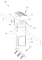
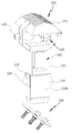
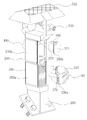
도2는 본 발명에 따른 도로 조명장치를 나타낸 사시도이며, 도3은 바디부의 외측바디가 하강 되었을 때, 본 발명에 따른 도로 조명장치를 나타낸 사시도이고, 그리고 도5는 본 발명에 따른 도로 조명장치의 B-B'선에 따른 단면사시도 및 부분확대도이다.Figure 2 is a perspective view showing a road lighting apparatus according to the present invention, Figure 3 is a perspective view showing a road lighting apparatus according to the present invention when the outer body of the body is lowered, and Figure 5 is a road lighting apparatus according to the present invention Sectional perspective view and partial enlarged view along line B-B '.
도2, 도3, 도5에 도시된 바와 같이, 본 발명에 따른 도로 조명장치(100)는, As shown in Figure 2, 3, 5, the
도로 조명장치(100)를 지지하며, 중앙선 일측 또는 중앙분리대와 체결되는 지지부(200)와 상기 지지부(200) 상부에 위치하여 내측바디(310)과 외측바디(330)의 2단으로 구성되며, 전·후면에 기상정보나 교통정보를 표시하는 디스플레이(350)를 구비하고, 제어모듈(600)의 지시에 따라 상기 외측바디(330)를 승강 또는 하강시키는 바디부(300)와, 상기 외측바디(330)의 좌·우측면에 설치되며, 지면을 향해 빛을 비추도록 바깥쪽으로 테이퍼지게 형성되는 조명부(400)와 상기 외측바디(330)가 하강시 외부로 노출되고, 풍력으로 회전하여 전기에너지를 생산하는 제1풍력발전모듈(390)과, 상기 바디부(300) 상부에 위치하며 풍력으로 회전하여 전기에너지를 생산하는 제2풍력발전모듈(590)과, 상기 제2풍력발전모듈(590) 상부에 지붕형태로 형성되어 태양 빛을 받아 전기를 생산하는 솔라셀 모듈(510)로 구성되는 헤드부(500)와. 조도센서(미도시)를 통해 감지된 조도 값을 기준 값과 비교하고, 비교결과에 따라 상기 조명부(400)를 제어하며, 축전지(700)의 전기충전량이 기준값 이하일 때, 상기 바디부(300)를 제어하는 제어모듈(600)을 포함하여 구성된다.It supports the
도6에 도시된 바와 같이, 상기 지지부(200)는 고속도로의 중앙분리대 또는 도로의 일측에 고정된다. 그리고 상기 지지부(200)가 중앙분리대에 설치될 경우에는 상기 지지부(200)는 중앙분리대와의 접촉면을 일치시키기 위해 사선의 형태를 가진다. 또한 중앙분리대와 체결은 볼트와 너트를 이용하는 것이 가장 바람직하다. 도6은 본 발명에 따른 도로 조명장치가 설치된 예시도이다.As shown in FIG. 6, the
그리고 상기 바디부(300)는 도5에 도시한 바와 같이, 상기 제1풍력발전모듈(390)의 각 모서리 부분에 블레이드(391, 591)의 회전시 방해가 되지 않도록 다수개의 엑추에이터(311)를 구비한다. 상기 엑추에이터(311)는 외측바디(330)와 연결되어 상기 외측바디(330)를 승·하강하도록 구동력을 제공한다.As shown in FIG. 5, the
이때, 상기 디스플레이(350)는 제1디스플레이(350a)와 제2디스플레이(350b)로 구성되며, 제1디스플레이(350a)와 제2디스플레이(350b)를 연동하여 디스플레이 동작을 수행한다. 상기 제1디스플레이(350a)는 상기 내측바디(310)에 설치되며, 상기 제2디스플레이(350b)는 외측바디(330)에 설치된다.In this case, the display 350 includes a
상기 디스플레이(350)는 그림, 문자 및 동영상을 출력할 수 있으며, 상기 외측바디(330)의 하강시 제1디스플레이(350a)의 구동은 중단된다. 또한, 상기 외측바디(330)가 상승하면 상기 제2디스플레이(350b)는 제1디스플레이(350a)와 연동되어 디스플레이를 수행한다.The display 350 may output pictures, texts, and videos, and the driving of the
또한 상기 각각의 디스플레이(350) 전면에는 상기 디스플레이(350)의 파손을 방지하기 위하여 강화유리(370)가 설치된다. 상기 강화유리(370)는 상기 디스플레이(350) 전면에 설치되어 외부로부터의 파편 또는 빗물 또는 그 밖의 이물질들을 차단한다.In addition, tempered
그리고 상기 조명부(400)는 상기 조도센서의 값이 기준 값 이하 일 때, 상기 제어모듈(600)의 지시에 따라 점등된다. 이때, 상기 조명부(400)는 도로에서 주행중인 차량의 속도를 감지할 수 있는 속도감지센서(410)를 구비하여 차량의 속도를 측정하여 과속시 카메라(530)를 통하여 차량의 사진을 찍음으로써, 과속차량을 단속하고, 차량의 평균속도를 교통통제실(800)로 전송하여 상기 교통통제실(800)에서 도로의 상황(예:정체, 서행, 원활)을 알 수 있다.When the value of the illuminance sensor is less than or equal to the reference value, the
예를 들어, 상기 전송된 차량의 평균속도가 0~20km/h인 경우 '정체', 20~50km/h인 경우 '서행', 50km/h인 경우 '원활'으로 상기 교통통제실(800)에 표시되어 도로의 상황을 쉽게 알 수 있다.For example, if the average speed of the transmitted vehicle is 0 ~ 20km / h, the traffic congestion to the
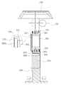
도4는 본 발명에 따른 도로 조명장치의 A-A'선에 따른 단면도 및 부분확대도이다.4 is a cross-sectional view and a partially enlarged view taken along line AA ′ of the road lighting apparatus according to the present invention.
도4에 도시한 바와 같이, 상기 제1풍력발전모듈(390) 및 제2풍력발전모듈(590)은 전기를 생산하기 위하여 회전축 둘레면에 설치되어 풍력에 의하여 회전하는 다수개의 블레이드(391, 591)와, 상기 회전축의 하단에 설치되는 다극(多極)자석형 회전자(393, 593)와, 하우징 내부에 배치되어 상기 회전자(393, 593)를 감싸도록 설치되는 고정자 코일(395, 595)과, 상기 회전축이 회전되면, 상기 축의 하단에 설치된 회전자(393, 593)의 자속(磁束)변화에 따라 상기 고정자 코일(395, 595)에서 전류를 발생시키도록 구성되는 제너레이터(397, 597)를 각각 더 포함하여 구성된다. 상기 제1 및 제2 풍력발전모듈(390, 590)로부터 생산된 전기는 축전지(700)에 저장된다.As shown in FIG. 4, the first wind
이때, 상기 헤드부(500)는 도로 조명장치(100)의 주위를 감시하고 차량을 촬영하는 적어도 하나 이상의 카메라(530)를 더 포함하여 구성된다.In this case, the
상기 카메라(530)는 좌,우,상,하 움직임이 가능하여 교통통제실(800)에서 보고자하는 방향으로 원격으로 조절될 수 있다.The
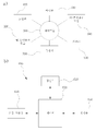
도 7은 본 발명에 따른 도로 조명장치의 시스템 구성도이며, 도 8의 a)는 본 발명에 따른 도로 조명장치의 블럭 구성도이고, 도 8의 b)는 본 발명에 따른 제어모듈의 블럭 구성도이다.7 is a system configuration diagram of a road lighting apparatus according to the present invention, Figure 8a) is a block diagram of a road lighting apparatus according to the present invention, Figure 8b) is a block configuration of a control module according to the present invention It is also.
도8에 도시한 바와 같이, 상기 제어모듈(600)은 교통통제실(800)과 유선망 또는 무선망을 통해 데이터를 송·수신하는 통신부(610)와, 도로 조명장치(100)의 각 구성요소들이 올바르게 작동되는 지를 점검하고, 작동의 오류시 오류정보를 상기 교통통제실(800)로 피드백하는 오류검출부(630)와, 도로 조명장치(100) 주변의 조도를 측정하는 센서부(650)와, 상기 교통통제실(800)의 지시에 따라 상기 조명부(400)를 제어하고, 교통통제실(800)로부터 수신되는 기상정보와 교통정보를 상기 디스플레이(350)에 출력하는 제어부(670)를 포함하여 구성된다.As shown in FIG. 8, the
또한, 상기 제어모듈(600)은 상기 축전지(700)의 전기충전량이 기준값 이하일 때, 상기 바디부(300)의 외측바디(330)를 하강시켜 상기 제1풍력발전모듈(390)이 외부로 노출되도록 제어한다.In addition, the
이때, 상기 통신부(610)는 CDMA(code division multiple access), GSM(Global System for Mobile communications), 와이파이(Wi-Fi), 와이브로(Wibro, Wireless broadband), 와이맥스 (Wimax, World Interoperability for Microwave Access), HSDPA(High Speed Downlink Packet Access), 마이크로웨이브(Microwave), PCS(Personal Communication Service) 방식 중 어느 하나에 따라 데이터 송수신을 수행한다.In this case, the
그리고, 상기 오류검출부(630)는 주기적으로 자체 검사를 통하여 각 구성장치의 작동여부를 체크하여 제어부(670)에 전송하며, 상기 제어부(670)는 받은 정보를 상기 통신부(610)를 통하여 상기 교통통제실(800)에 전송한다.In addition, the
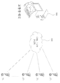
마지막으로, 도7에 도시된 바와 같이 상기 도로 조명장치(100)는 지역 또는 도로의 번호에 따라 고유번호가 할당되며, 상기 교통통제실(800)은 지역, 도로의 번호 또는 도로 구간별로 구분된 상기 도로 조명장치(100)를 유·무선 통신망(900)을 통하여 전체 또는 부분제어가 가능하다.Finally, as shown in Figure 7, the
이상에서 설명한 본 발명의 바람직한 실시예에 대하여 상세하게 설명하였지만 당해 기술분야에서 통산의 지식을 가진 자라면 이로부터 다양한 변형 및 균등한 타 실시예가 가능하다는 점을 이해할 수 있을 것이다.Although the preferred embodiment of the present invention has been described in detail above, those skilled in the art will understand that various modifications and equivalent other embodiments are possible therefrom.
따라서, 본 발명의 권리 범위는 개시된 실시예에 한정되는 것은 아니고 다음의 청구범위에서 정의하고 있는 본 발명의 기본 개념을 이용한 당업자의 여러 변경 및 개량 형태 또는 본 발명의 권리 범위에 속하는 것으로 보아야 할 것이다.Accordingly, the scope of the present invention should not be limited to the disclosed embodiments but should be regarded as belonging to various modifications and improvements of those skilled in the art using the basic concept of the present invention as defined in the following claims, or the scope of the present invention. .
도로 조명장치 : 100 지지부 : 200
바디부 : 300
내측바디 : 310 엑추에이터 : 311
외측바디 : 330 디스플레이 : 350
제1디스플레이 : 350a 제2디스플레이 : 350b
강화유리 : 370 제1풍력발전모듈 : 390
조명부 : 400 속도감지센서 : 410
헤드부 : 500
솔라셀모듈 : 510 카메라 : 530
제2풍력발전모듈 : 590
제어모듈 : 600
통신부 : 610 오류검출부 : 630
센서부 : 650 제어부 : 670
블레이드 : 391, 591 회전자 : 393, 593
코일 : 395, 595 제너레이터 : 397, 597
축전지 : 700 교통통제실 : 800
통신망 : 900Road Lighting: 100 Support: 200
Body part: 300
Inner Body: 310 Actuator: 311
Outer body: 330 Display: 350
1st display: 350a 2nd display: 350b
Tempered Glass: 370 First Wind Power Generation Module: 390
Lighting part: 400 Speed sensor: 410
Head: 500
Cell Module: 510 Camera: 530
Second wind power generation module: 590
Control module: 600
Communication unit: 610 Error detection unit: 630
Sensor part: 650 Control part: 670
Blade: 391, 591 Rotor: 393, 593
Coil: 395, 595 Generator: 397, 597
Storage Battery: 700 Traffic Control Room: 800
Communication network: 900
Claims (9)
상기 지지부 상부에 위치하여 내측바디과 외측바디의 2단으로 구성되며, 전·후면에 기상정보나 교통정보를 표시하는 디스플레이를 구비하고, 제어모듈의 지시에 따라 상기 외측바디를 승강 또는 하강시키는 바디부와;
상기 외측바디의 좌·우측면에 설치되며, 지면을 향해 빛을 비추도록 바깥쪽으로 테이퍼지게 형성되는 조명부와;
상기 외측바디가 하강시 외부로 노출되고, 풍력으로 회전하여 전기에너지를 생산하는 제1풍력발전모듈과;
상기 바디부 상부에 위치하며 풍력으로 회전하여 전기에너지를 생산하는 제2풍력발전모듈과, 상기 제2풍력발전모듈 상부에 지붕형태로 형성되어 태양 빛을 받아 전기를 생산하는 솔라셀 모듈로 구성되는 헤드부와;
조도센서를 통해 감지된 조도 값을 기준 값과 비교하고, 비교결과에 따라 상기 조명부를 제어하며, 축전지의 전기충전량이 기준값 이하일 때, 상기 바디부를 제어하는 제어모듈을 포함하여 구성되는 것을 특징으로 하는 도로 조명장치.Supporting the road lighting device, the support portion is fastened to the central line one side or the central separator;
Located in the upper part of the support portion is composed of two stages of the inner body and the outer body, and having a display for displaying weather information or traffic information on the front and rear, and the body portion for lifting or lowering the outer body according to the instructions of the control module Wow;
An illumination unit installed on the left and right sides of the outer body and tapered outward to shine light toward the ground;
A first wind power generation module which is exposed to the outside when the outer body is lowered and rotates with wind power to produce electrical energy;
Located in the upper part of the body portion and rotated by wind power to produce electrical energy, and the second wind power generating module is formed of a roof shape on the top of the solar cell module is configured to receive electricity A head portion;
And a control module for comparing the illuminance value detected by the illuminance sensor with a reference value, controlling the lighting unit according to the comparison result, and controlling the body unit when the amount of charge of the battery is less than the reference value. Road lighting.
상기 외측바디의 승강 또는 하강에 구동력을 제공하는 다수개의 엑추에이터를 더 포함하여 구성되는 것을 특징으로 하는 도로 조명장치.The method of claim 1, wherein the body portion
Road lighting apparatus further comprises a plurality of actuators for providing a driving force to the lifting or lowering of the outer body.
상기 조도센서의 값이 기준 값 이하 일 때, 상기 제어모듈의 지시에 의해 점등되는 것을 특징으로 하는 도로 조명장치.The method of claim 1, wherein the lighting unit
And when the value of the illuminance sensor is equal to or less than a reference value, the road lighting apparatus is turned on by an instruction of the control module.
도로에서 이동중인 차량의 속도를 측정하는 속도감지센서를 더 포함하여 구성되는 것을 특징으로 하는 도로 조명장치.The method of claim 1, wherein the lighting unit
Road lighting apparatus further comprises a speed sensor for measuring the speed of the vehicle moving on the road.
회전축 둘레면에 설치되어 풍력에 의하여 회전하는 다수개의 블레이드와;
상기 회전축의 하단에 설치되는 다극(多極)자석형 회전자와;
하우징 내부에 배치되어 상기 회전자를 감싸도록 설치되는 고정자 코일과;
상기 회전축이 회전되면, 상기 축의 하단에 설치된 회전자의 자속(磁束)변화에 따라 상기 고정자 코일에서 전류를 발생시키도록 구성되는 제너레이터를 각각 더 포함하는 것을 특징으로 하는 도로 조명장치.The method of claim 1, wherein the first wind power generation module and the second wind power generation module
A plurality of blades installed on the circumferential surface of the rotating shaft and rotating by wind power;
A multi-pole magnet rotor installed at the lower end of the rotating shaft;
A stator coil disposed inside the housing and installed to surround the rotor;
And a generator configured to generate a current in the stator coils according to a change in magnetic flux of the rotor installed at the lower end of the shaft when the rotating shaft is rotated.
도로 조명장치의 주위를 감시하고 촬영하는 적어도 하나 이상의 카메라를 더 포함하여 구성되는 것을 특징으로 하는 도로 조명장치.The method of claim 1, wherein the head portion
The road lighting apparatus further comprises at least one camera for monitoring and photographing the surroundings of the road lighting apparatus.
교통통제실과 유선망 또는 무선망을 통해 데이터를 송·수신하는 통신부와;
도로 조명장치의 각 구성요소들이 올바르게 작동되는 지를 점검하고, 작동의 오류시 오류정보를 상기 교통통제실로 피드백하는 오류검출부와;
도로 조명장치 주변의 조도를 측정하는 센서부와;
상기 교통통제실의 지시에 따라 상기 조명부를 제어하고, 교통통제실로부터 수신되는 기상정보와 교통정보를 상기 디스플레이에 출력하는 제어부를 더 포함하여 구성되는 것을 특징으로 하는 도로 조명장치.The method of claim 1, wherein the control module
A communication unit for transmitting and receiving data through a traffic control room and a wired or wireless network;
An error detection unit for checking whether each component of the road lighting apparatus is operated correctly and feeding back error information to the traffic control room in case of an error of operation;
A sensor unit for measuring illuminance around the road lighting apparatus;
And a controller for controlling the lighting unit according to the instruction of the traffic control room and outputting weather information and traffic information received from the traffic control room to the display.
CDMA(code division multiple access), GSM(Global System for Mobile communications), 와이파이(Wi-Fi), 와이브로(Wibro, Wireless broadband), 와이맥스 (Wimax, World Interoperability for Microwave Access), HSDPA(High Speed Downlink Packet Access), 마이크로웨이브(Microwave), PCS(Personal Communication Service) 방식 중 어느 하나에 따라 데이터 송수신을 수행하는 것을 특징으로 하는 도로 조명장치.The method of claim 7, wherein the communication unit
Code division multiple access (CDMA), Global System for Mobile communications (GSM), Wi-Fi, Wibro, Wireless broadband, Wimax (World Interoperability for Microwave Access), High Speed Downlink Packet Access ), A road lighting apparatus for performing data transmission and reception according to any one of the microwave (Microwave), PCS (Personal Communication Service) method.
상기 축전지의 전기충전량이 기준값 이하일 때, 상기 바디부의 외측바디를 하강시켜 상기 제1풍력발전모듈이 외부로 노출되도록 제어하는 것을 특징으로 하는 도로 조명장치.The method of claim 1, wherein the control module
When the electric charge of the battery is less than the reference value, the road lighting device characterized in that the outer body by lowering the body portion is controlled to expose the first wind power generation module to the outside.
Priority Applications (1)
| Application Number | Priority Date | Filing Date | Title |
|---|---|---|---|
| KR1020110090662A KR20130027212A (en) | 2011-09-07 | 2011-09-07 | Lighting device of road |
Applications Claiming Priority (1)
| Application Number | Priority Date | Filing Date | Title |
|---|---|---|---|
| KR1020110090662A KR20130027212A (en) | 2011-09-07 | 2011-09-07 | Lighting device of road |
Publications (1)
| Publication Number | Publication Date |
|---|---|
| KR20130027212A true KR20130027212A (en) | 2013-03-15 |
Family
ID=48178220
Family Applications (1)
| Application Number | Title | Priority Date | Filing Date |
|---|---|---|---|
| KR1020110090662A KR20130027212A (en) | 2011-09-07 | 2011-09-07 | Lighting device of road |
Country Status (1)
| Country | Link |
|---|---|
| KR (1) | KR20130027212A (en) |
Cited By (12)
| Publication number | Priority date | Publication date | Assignee | Title |
|---|---|---|---|---|
| KR101475224B1 (en) * | 2014-04-22 | 2014-12-31 | 중앙대학교 산학협력단 | Wireless and powerless illumination control device |
| CN105913763A (en) * | 2016-05-27 | 2016-08-31 | 合肥中海信息科技有限公司 | Convenient mobile wind and solar energy electronic message sign |
| CN105931570A (en) * | 2016-05-27 | 2016-09-07 | 合肥中海信息科技有限公司 | Movable solar electronic information board |
| CN105976703A (en) * | 2016-05-27 | 2016-09-28 | 合肥中海信息科技有限公司 | Wind and solar energy electronic information board |
| CN106097887A (en) * | 2016-05-27 | 2016-11-09 | 合肥中海信息科技有限公司 | A kind of solar energy electronic message board |
| KR101678145B1 (en) * | 2016-09-05 | 2016-11-23 | 주식회사 동해종합기술공사 | Power Supply Control system for measuring device of speed type hybrid |
| EP3343540A1 (en) * | 2015-07-07 | 2018-07-04 | Juan Francisco Cepero Ramirez | Multifunctional street lighting post |
| KR20190006118A (en) * | 2017-07-06 | 2019-01-17 | 한국도로공사 | Height control type streetlight |
| KR101971820B1 (en) * | 2018-01-05 | 2019-04-23 | 주식회사 에스앤더블유 | Pole structure having hybrid functions based on green energy |
| CN109785739A (en) * | 2019-01-28 | 2019-05-21 | 温州商学院 | A kind of landscape garden new energy direction board |
| KR102414464B1 (en) * | 2022-03-24 | 2022-06-30 | 주식회사 한국퓨처에코테크 | Hybrid power generation system using wind and solar power |
| KR20230016310A (en) * | 2021-07-26 | 2023-02-02 | 원 식 윤 | Hologram image providing system through the reuse of eco-friendly solar energy and renewable lithium-ion batteries |
-
2011
- 2011-09-07 KR KR1020110090662A patent/KR20130027212A/en active IP Right Grant
Cited By (12)
| Publication number | Priority date | Publication date | Assignee | Title |
|---|---|---|---|---|
| KR101475224B1 (en) * | 2014-04-22 | 2014-12-31 | 중앙대학교 산학협력단 | Wireless and powerless illumination control device |
| EP3343540A1 (en) * | 2015-07-07 | 2018-07-04 | Juan Francisco Cepero Ramirez | Multifunctional street lighting post |
| CN105913763A (en) * | 2016-05-27 | 2016-08-31 | 合肥中海信息科技有限公司 | Convenient mobile wind and solar energy electronic message sign |
| CN105931570A (en) * | 2016-05-27 | 2016-09-07 | 合肥中海信息科技有限公司 | Movable solar electronic information board |
| CN105976703A (en) * | 2016-05-27 | 2016-09-28 | 合肥中海信息科技有限公司 | Wind and solar energy electronic information board |
| CN106097887A (en) * | 2016-05-27 | 2016-11-09 | 合肥中海信息科技有限公司 | A kind of solar energy electronic message board |
| KR101678145B1 (en) * | 2016-09-05 | 2016-11-23 | 주식회사 동해종합기술공사 | Power Supply Control system for measuring device of speed type hybrid |
| KR20190006118A (en) * | 2017-07-06 | 2019-01-17 | 한국도로공사 | Height control type streetlight |
| KR101971820B1 (en) * | 2018-01-05 | 2019-04-23 | 주식회사 에스앤더블유 | Pole structure having hybrid functions based on green energy |
| CN109785739A (en) * | 2019-01-28 | 2019-05-21 | 温州商学院 | A kind of landscape garden new energy direction board |
| KR20230016310A (en) * | 2021-07-26 | 2023-02-02 | 원 식 윤 | Hologram image providing system through the reuse of eco-friendly solar energy and renewable lithium-ion batteries |
| KR102414464B1 (en) * | 2022-03-24 | 2022-06-30 | 주식회사 한국퓨처에코테크 | Hybrid power generation system using wind and solar power |
Similar Documents
| Publication | Publication Date | Title |
|---|---|---|
| KR20130027212A (en) | Lighting device of road | |
| CN204442798U (en) | A kind of Intelligent road lamp supervisory control system controlled by high in the clouds | |
| KR101023014B1 (en) | Hybrid streetlight | |
| CN111928174A (en) | Multifunctional modular intelligent lamp pole and implementation method thereof | |
| CN205782513U (en) | A kind of multi-functional street lamp | |
| CN105375860A (en) | Wind-light combination type intelligent sun tracking power supply system | |
| EP2618450A1 (en) | Lighting and communication device for ultra-wide band networks | |
| CN202118763U (en) | Energy-saving street lamp | |
| CN209691104U (en) | A kind of intelligent solar traffic lights | |
| CN201836799U (en) | Unnatural wind power comprehensive utilization illuminating device | |
| KR101513832B1 (en) | Flag hoist system | |
| KR101301734B1 (en) | Flag hoist system | |
| CN106122879B (en) | A kind of energy-saving LED road lamp control method | |
| CN112879857A (en) | City wisdom street lighting | |
| CN106402787A (en) | Streetlamp and control system thereof | |
| KR101433718B1 (en) | Advertising equipment using street lamp pole | |
| CN110700147A (en) | Luminous guardrail system on inner side of bidirectional lane of road | |
| CN204387931U (en) | A kind of solar street light | |
| CN101994979A (en) | Unnatural wind power comprehensive utilization illumination device | |
| KR101233125B1 (en) | placards stand control method | |
| KR20060061502A (en) | Flasher for road | |
| KR20110056615A (en) | A wind force generation device for traffic equipment | |
| CN212273903U (en) | Multi-functional DIY lamp pole | |
| CN210836562U (en) | Intelligent LED traffic signal lamp | |
| KR20100007583A (en) | Self generation type street light installed rotary signboard |
Legal Events
| Date | Code | Title | Description |
|---|---|---|---|
| A201 | Request for examination | ||
| E902 | Notification of reason for refusal | ||
| E701 | Decision to grant or registration of patent right | ||
| NORF | Unpaid initial registration fee |