KR20130018726A - Enhanced viewing brightness for surface display - Google Patents
Enhanced viewing brightness for surface display Download PDFInfo
- Publication number
- KR20130018726A KR20130018726A KR1020127025438A KR20127025438A KR20130018726A KR 20130018726 A KR20130018726 A KR 20130018726A KR 1020127025438 A KR1020127025438 A KR 1020127025438A KR 20127025438 A KR20127025438 A KR 20127025438A KR 20130018726 A KR20130018726 A KR 20130018726A
- Authority
- KR
- South Korea
- Prior art keywords
- light
- array
- display panel
- diffuser
- intensity profile
- Prior art date
Links
Images


Classifications
-
- G—PHYSICS
- G03—PHOTOGRAPHY; CINEMATOGRAPHY; ANALOGOUS TECHNIQUES USING WAVES OTHER THAN OPTICAL WAVES; ELECTROGRAPHY; HOLOGRAPHY
- G03B—APPARATUS OR ARRANGEMENTS FOR TAKING PHOTOGRAPHS OR FOR PROJECTING OR VIEWING THEM; APPARATUS OR ARRANGEMENTS EMPLOYING ANALOGOUS TECHNIQUES USING WAVES OTHER THAN OPTICAL WAVES; ACCESSORIES THEREFOR
- G03B21/00—Projectors or projection-type viewers; Accessories therefor
-
- G—PHYSICS
- G02—OPTICS
- G02B—OPTICAL ELEMENTS, SYSTEMS OR APPARATUS
- G02B5/00—Optical elements other than lenses
- G02B5/02—Diffusing elements; Afocal elements
-
- G—PHYSICS
- G02—OPTICS
- G02B—OPTICAL ELEMENTS, SYSTEMS OR APPARATUS
- G02B5/00—Optical elements other than lenses
- G02B5/02—Diffusing elements; Afocal elements
- G02B5/0205—Diffusing elements; Afocal elements characterised by the diffusing properties
- G02B5/0236—Diffusing elements; Afocal elements characterised by the diffusing properties the diffusion taking place within the volume of the element
- G02B5/0242—Diffusing elements; Afocal elements characterised by the diffusing properties the diffusion taking place within the volume of the element by means of dispersed particles
-
- G—PHYSICS
- G02—OPTICS
- G02B—OPTICAL ELEMENTS, SYSTEMS OR APPARATUS
- G02B5/00—Optical elements other than lenses
- G02B5/04—Prisms
- G02B5/045—Prism arrays
-
- G—PHYSICS
- G02—OPTICS
- G02F—OPTICAL DEVICES OR ARRANGEMENTS FOR THE CONTROL OF LIGHT BY MODIFICATION OF THE OPTICAL PROPERTIES OF THE MEDIA OF THE ELEMENTS INVOLVED THEREIN; NON-LINEAR OPTICS; FREQUENCY-CHANGING OF LIGHT; OPTICAL LOGIC ELEMENTS; OPTICAL ANALOGUE/DIGITAL CONVERTERS
- G02F1/00—Devices or arrangements for the control of the intensity, colour, phase, polarisation or direction of light arriving from an independent light source, e.g. switching, gating or modulating; Non-linear optics
- G02F1/01—Devices or arrangements for the control of the intensity, colour, phase, polarisation or direction of light arriving from an independent light source, e.g. switching, gating or modulating; Non-linear optics for the control of the intensity, phase, polarisation or colour
- G02F1/13—Devices or arrangements for the control of the intensity, colour, phase, polarisation or direction of light arriving from an independent light source, e.g. switching, gating or modulating; Non-linear optics for the control of the intensity, phase, polarisation or colour based on liquid crystals, e.g. single liquid crystal display cells
- G02F1/133—Constructional arrangements; Operation of liquid crystal cells; Circuit arrangements
- G02F1/1333—Constructional arrangements; Manufacturing methods
- G02F1/1335—Structural association of cells with optical devices, e.g. polarisers or reflectors
- G02F1/133504—Diffusing, scattering, diffracting elements
-
- G—PHYSICS
- G02—OPTICS
- G02F—OPTICAL DEVICES OR ARRANGEMENTS FOR THE CONTROL OF LIGHT BY MODIFICATION OF THE OPTICAL PROPERTIES OF THE MEDIA OF THE ELEMENTS INVOLVED THEREIN; NON-LINEAR OPTICS; FREQUENCY-CHANGING OF LIGHT; OPTICAL LOGIC ELEMENTS; OPTICAL ANALOGUE/DIGITAL CONVERTERS
- G02F1/00—Devices or arrangements for the control of the intensity, colour, phase, polarisation or direction of light arriving from an independent light source, e.g. switching, gating or modulating; Non-linear optics
- G02F1/01—Devices or arrangements for the control of the intensity, colour, phase, polarisation or direction of light arriving from an independent light source, e.g. switching, gating or modulating; Non-linear optics for the control of the intensity, phase, polarisation or colour
- G02F1/13—Devices or arrangements for the control of the intensity, colour, phase, polarisation or direction of light arriving from an independent light source, e.g. switching, gating or modulating; Non-linear optics for the control of the intensity, phase, polarisation or colour based on liquid crystals, e.g. single liquid crystal display cells
- G02F1/133—Constructional arrangements; Operation of liquid crystal cells; Circuit arrangements
- G02F1/1333—Constructional arrangements; Manufacturing methods
- G02F1/1335—Structural association of cells with optical devices, e.g. polarisers or reflectors
- G02F1/133526—Lenses, e.g. microlenses or Fresnel lenses
-
- G—PHYSICS
- G02—OPTICS
- G02F—OPTICAL DEVICES OR ARRANGEMENTS FOR THE CONTROL OF LIGHT BY MODIFICATION OF THE OPTICAL PROPERTIES OF THE MEDIA OF THE ELEMENTS INVOLVED THEREIN; NON-LINEAR OPTICS; FREQUENCY-CHANGING OF LIGHT; OPTICAL LOGIC ELEMENTS; OPTICAL ANALOGUE/DIGITAL CONVERTERS
- G02F1/00—Devices or arrangements for the control of the intensity, colour, phase, polarisation or direction of light arriving from an independent light source, e.g. switching, gating or modulating; Non-linear optics
- G02F1/01—Devices or arrangements for the control of the intensity, colour, phase, polarisation or direction of light arriving from an independent light source, e.g. switching, gating or modulating; Non-linear optics for the control of the intensity, phase, polarisation or colour
- G02F1/13—Devices or arrangements for the control of the intensity, colour, phase, polarisation or direction of light arriving from an independent light source, e.g. switching, gating or modulating; Non-linear optics for the control of the intensity, phase, polarisation or colour based on liquid crystals, e.g. single liquid crystal display cells
- G02F1/133—Constructional arrangements; Operation of liquid crystal cells; Circuit arrangements
- G02F1/1333—Constructional arrangements; Manufacturing methods
- G02F1/1335—Structural association of cells with optical devices, e.g. polarisers or reflectors
- G02F1/1336—Illuminating devices
- G02F1/133602—Direct backlight
- G02F1/133606—Direct backlight including a specially adapted diffusing, scattering or light controlling members
-
- G—PHYSICS
- G03—PHOTOGRAPHY; CINEMATOGRAPHY; ANALOGOUS TECHNIQUES USING WAVES OTHER THAN OPTICAL WAVES; ELECTROGRAPHY; HOLOGRAPHY
- G03B—APPARATUS OR ARRANGEMENTS FOR TAKING PHOTOGRAPHS OR FOR PROJECTING OR VIEWING THEM; APPARATUS OR ARRANGEMENTS EMPLOYING ANALOGOUS TECHNIQUES USING WAVES OTHER THAN OPTICAL WAVES; ACCESSORIES THEREFOR
- G03B21/00—Projectors or projection-type viewers; Accessories therefor
- G03B21/005—Projectors using an electronic spatial light modulator but not peculiar thereto
-
- G—PHYSICS
- G03—PHOTOGRAPHY; CINEMATOGRAPHY; ANALOGOUS TECHNIQUES USING WAVES OTHER THAN OPTICAL WAVES; ELECTROGRAPHY; HOLOGRAPHY
- G03B—APPARATUS OR ARRANGEMENTS FOR TAKING PHOTOGRAPHS OR FOR PROJECTING OR VIEWING THEM; APPARATUS OR ARRANGEMENTS EMPLOYING ANALOGOUS TECHNIQUES USING WAVES OTHER THAN OPTICAL WAVES; ACCESSORIES THEREFOR
- G03B21/00—Projectors or projection-type viewers; Accessories therefor
- G03B21/10—Projectors with built-in or built-on screen
-
- G—PHYSICS
- G03—PHOTOGRAPHY; CINEMATOGRAPHY; ANALOGOUS TECHNIQUES USING WAVES OTHER THAN OPTICAL WAVES; ELECTROGRAPHY; HOLOGRAPHY
- G03B—APPARATUS OR ARRANGEMENTS FOR TAKING PHOTOGRAPHS OR FOR PROJECTING OR VIEWING THEM; APPARATUS OR ARRANGEMENTS EMPLOYING ANALOGOUS TECHNIQUES USING WAVES OTHER THAN OPTICAL WAVES; ACCESSORIES THEREFOR
- G03B21/00—Projectors or projection-type viewers; Accessories therefor
- G03B21/54—Accessories
- G03B21/56—Projection screens
- G03B21/60—Projection screens characterised by the nature of the surface
- G03B21/62—Translucent screens
- G03B21/625—Lenticular translucent screens
-
- G—PHYSICS
- G09—EDUCATION; CRYPTOGRAPHY; DISPLAY; ADVERTISING; SEALS
- G09F—DISPLAYING; ADVERTISING; SIGNS; LABELS OR NAME-PLATES; SEALS
- G09F9/00—Indicating arrangements for variable information in which the information is built-up on a support by selection or combination of individual elements
- G09F9/30—Indicating arrangements for variable information in which the information is built-up on a support by selection or combination of individual elements in which the desired character or characters are formed by combining individual elements
- G09F9/35—Indicating arrangements for variable information in which the information is built-up on a support by selection or combination of individual elements in which the desired character or characters are formed by combining individual elements being liquid crystals
-
- H—ELECTRICITY
- H04—ELECTRIC COMMUNICATION TECHNIQUE
- H04N—PICTORIAL COMMUNICATION, e.g. TELEVISION
- H04N5/00—Details of television systems
-
- G—PHYSICS
- G02—OPTICS
- G02F—OPTICAL DEVICES OR ARRANGEMENTS FOR THE CONTROL OF LIGHT BY MODIFICATION OF THE OPTICAL PROPERTIES OF THE MEDIA OF THE ELEMENTS INVOLVED THEREIN; NON-LINEAR OPTICS; FREQUENCY-CHANGING OF LIGHT; OPTICAL LOGIC ELEMENTS; OPTICAL ANALOGUE/DIGITAL CONVERTERS
- G02F1/00—Devices or arrangements for the control of the intensity, colour, phase, polarisation or direction of light arriving from an independent light source, e.g. switching, gating or modulating; Non-linear optics
- G02F1/01—Devices or arrangements for the control of the intensity, colour, phase, polarisation or direction of light arriving from an independent light source, e.g. switching, gating or modulating; Non-linear optics for the control of the intensity, phase, polarisation or colour
- G02F1/13—Devices or arrangements for the control of the intensity, colour, phase, polarisation or direction of light arriving from an independent light source, e.g. switching, gating or modulating; Non-linear optics for the control of the intensity, phase, polarisation or colour based on liquid crystals, e.g. single liquid crystal display cells
- G02F1/133—Constructional arrangements; Operation of liquid crystal cells; Circuit arrangements
- G02F1/1333—Constructional arrangements; Manufacturing methods
- G02F1/1335—Structural association of cells with optical devices, e.g. polarisers or reflectors
- G02F1/1336—Illuminating devices
- G02F1/133602—Direct backlight
- G02F1/133606—Direct backlight including a specially adapted diffusing, scattering or light controlling members
- G02F1/133607—Direct backlight including a specially adapted diffusing, scattering or light controlling members the light controlling member including light directing or refracting elements, e.g. prisms or lenses
Abstract
디스플레이 패널은 기판에 배열된 굴절 요소 어레이를 포함한다. 어레이는 제 1 강도 프로파일의 빛을 수신하도록 배치되고, 수신된 빛의 적어도 일부를 제 2 강도 프로파일로 전송하도록 구성된다. 디스플레이 패널은 또한, 굴절 요소 어레이에 의해 전송된 빛을 수신하도록 배치되고, 수신된 빛의 적어도 일부를 제 3 강도 프로파일로 전송하도록 구성되는 산광기를 포함한다. 제 2 강도 프로파일은 제 1 강도 프로파일보다 기판층에 대해 수직으로 낮은 상대 강도를 가진다.The display panel includes an array of refractive elements arranged on the substrate. The array is arranged to receive light of the first intensity profile and is configured to transmit at least a portion of the received light to the second intensity profile. The display panel also includes a diffuser arranged to receive light transmitted by the array of refractive elements and configured to transmit at least a portion of the received light to the third intensity profile. The second intensity profile has a lower relative strength perpendicular to the substrate layer than the first intensity profile.

Description
디스플레이 패널은 여러 명의 시청자(viewer)들에 대한 패널의 배향(orientation)에 따라 다양한 각도로 보여질 수 있다. 디스플레이 패널을 보게 되는 많은 애플리케이션에서, 이런 배향은 예측 가능한 범위에 들어간다. 예를 들어, TV 시청 및 컴퓨터 모니터를 이용하는 경우, 시청자들은 디스플레이 패널 바로 앞에 앉거나, 또는 최소한 디스플레이 패널과 같은 눈높이에 있게 앉을 수 있다. 따라서, 이들 애플리케이션에 사용되는 디스플레이 패널은 디스플레이 패널 표면에 수직일 때 최대 광도(maximum light intensity)를 내도록 구성될 수 있고, 광도는 시야각(viewing angle)의 증가에 따라 등방성으로(isotropically) 또는 이방성으로(anisotropically) 줄어들게 된다. 하지만, 이런 구성은 시청자들이 디스플레이 패널과 같은 눈높이에 있지 않거나 디스플레이 패널 바로 앞에 앉아 있지않은 애플리케이션에서, 이용 가능한 빛 에너지를 비효율적으로 분배하게 될 수 있다.
The display panel can be viewed at various angles depending on the orientation of the panel with respect to several viewers. In many applications where one sees a display panel, this orientation falls within the predictable range. For example, with TV viewing and computer monitors, viewers may sit directly in front of the display panel, or at least at eye level, such as the display panel. Thus, display panels used in these applications can be configured to produce maximum light intensity when perpendicular to the display panel surface, the brightness being isotropically or anisotropic with increasing viewing angle. (anisotropically) is reduced. However, this configuration may result in inefficient distribution of available light energy in applications where viewers are not at eye level, such as a display panel, or sitting in front of the display panel.
따라서, 일 실시예에서 기판에 배열된 굴절 구성요소(refractive element) 어레이를 포함하는 디스플레이 패널이 제공된다. 어레이는 제 1 강도 프로파일(intensity profile)의 빛을 수신하도록 배치되고, 수신된 빛의 적어도 일부를 제 2 강도 프로파일로 전송하도록 구성된다. 본 실시예에서, 제 2 강도 프로파일은 제 1 강도 프로파일에 비해, 기판에 대해 수직으로는 보다 낮은 상대 강도(lower relative intensity)를 갖고, 기판에 대해 경사진 방향으로는 보다 높은 상대 강도를 가지고 있다.Thus, in one embodiment, a display panel is provided that includes an array of refractive elements arranged on a substrate. The array is arranged to receive light of a first intensity profile and is configured to transmit at least a portion of the received light to the second intensity profile. In this embodiment, the second intensity profile has a lower relative intensity perpendicular to the substrate and a higher relative intensity in the inclined direction relative to the substrate as compared to the first intensity profile. .
본 요약은 아래의 상세한 설명에서 추가적으로 설명되는 일련의 개념을 간략한 형태로 소개한다. 본 요약은 특허 청구된 대상의 핵심 특징이나 필수 특징을 밝히기 위한 것이 아니며, 특허 청구된 대상의 범위는 상세한 설명에 뒤이어 나오는 특허 청구 범위에 의해 정의된다. 또한, 특허 청구된 대상은 본원에서 언급된 임의의 단점을 해결하는 구현에 한정되지 않는다.
This summary introduces a series of concepts in a simplified form that are further described below in the Detailed Description. This Summary is not intended to identify key features or essential features of the claimed subject matter, and the scope of the claimed subject matter is defined by the following claims. In addition, the claimed subject matter is not limited to implementations that solve any disadvantages mentioned herein.
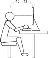
도 1은 시청자 및 수직으로 배향된 디스플레이 패널을 포함하는 참조적인 배치를 개략적으로 도시한다.
도 2는 본 개시의 실시예에 따른 시청자 및 수평으로 배향된, 대형 디스플레이 패널을 포함하는 예시적인 배치를 개략적으로 도시한다.
도 3은 본 개시의 실시예에 따른 디스플레이 패널이 내는 빛에 대한 바람직한 강도 프로파일의 그래프를 도시한다.
도 4는 본 개시의 실시예에 따른 디스플레이 패널을 위한 예시적인 광학 시스템(optical system)의 양태들을 개략적으로 도시한다.
도 5는 본 개시의 실시예에 따른 광학 시스템의 각도-확대층(angle-expanding layer)의 수직 단면도를 개략적으로 도시한다.
도 6은 본 개시의 실시예에 따른 광학 시스템의 예시적인 마이크로 구조 굴절기(microstructured refractor)를 도시한다.
도 7 및 8은 본 개시의 실시예에 따른 광학 시스템의 예시적인 다른 각도-확대층의 수직 단면도를 도시한다.
도 9는 본 개시의 실시예에 따른 디스플레이 패널을 위한 예시적인 다른 광학 시스템의 양태들을 개략적으로 도시한다.1 schematically shows a reference arrangement comprising a viewer and a vertically oriented display panel.
2 schematically illustrates an example arrangement comprising a viewer and a horizontally oriented, large display panel in accordance with an embodiment of the present disclosure.
3 shows a graph of a preferred intensity profile for light emitted by a display panel according to an embodiment of the disclosure.
4 schematically illustrates aspects of an exemplary optical system for a display panel according to an embodiment of the disclosure.
5 schematically illustrates a vertical cross-sectional view of an angle-expanding layer of an optical system according to an embodiment of the present disclosure.
6 illustrates an example microstructured refractor of an optical system according to an embodiment of the present disclosure.
7 and 8 illustrate vertical cross-sectional views of another exemplary angle-enlarging layer of an optical system according to an embodiment of the present disclosure.
9 schematically illustrates aspects of another exemplary optical system for a display panel according to an embodiment of the present disclosure.
본 개시의 대상은 예시를 통해 또한, 도시된 특정 실시예를 참조하여 설명된다. 하나 이상의 실시예에서 실질적으로 동일한 컴포넌트들은 대등하게 식별된다. 그러나, 대등하게 식별된 컴포넌트들은 어느 정도는 상이할 수 있음을 알 것이다. 또한, 본 개시에 포함된 도면은 개략적인 것으로, 일반적으로 일정한 비율로 그려진 것이 아님을 알 것이다. 그보다는, 도면에 도시된 컴포넌트들의 각종 도시 비율, 형상비(aspect ratios), 개수는 특정 특징이나 관계를 보다 쉽게 볼 수 있도록 의도적으로 왜곡된 것일 수 있다.The subject matter of the present disclosure is described by way of example and with reference to the specific embodiments shown. In one or more embodiments substantially the same components are identified equally. However, it will be appreciated that equivalently identified components may be somewhat different. In addition, it will be appreciated that the drawings included in the present disclosure are schematic and are not generally drawn to scale. Rather, various illustrated ratios, aspect ratios, and number of components shown in the figures may be intentionally distorted to more easily view particular features or relationships.
도 1은 시청자(10) 및 수직으로 배향된 디스플레이 패널(12)을 포함하는 참조적인 배치를 개략적으로 도시한다. 도 1에서, 시청자는 디스플레이 패널의 바로 앞에 앉아 있다. 따라서, 디스플레이 패널에서 내는 빛의 강도 프로파일은 수직 배향에 대해 최적화되어 있을 수 있다. '강도 프로파일'이라는 용어는 시야각의 함수인 빛의 힘(power) 또는 광속(flux)을 나타내기 위해 본원에서 사용된다. 특히, 디스플레이 패널은 그 전면(front surface)에 대해 수직일 때 - 즉, 표면 법선(surface normal)에 대해 0도에서 최대 광도를 내도록 구성될 수 있다. 이런 구성은 보여질 가능성이 높은 각도 범위에서 발광함으로써, 이용 가능한 빛 에너지를 효율적으로 사용한다. 이와 같은 구성에서, 광도는 시야각이 증가할수록, 가우시안(Gaussian) 또는 램버시안(Lambertian) 프로파일에 따라 혹은 램버시안 프로파일의 이방성 곱(anisotropic product)에 따라 감소할 수 있다. 예를 들어, 광도는 수직 방향으로 시야각이 증가하면 급격하게 감소되고, 수평 방향으로 시야각이 증가하면 더 완만하게 감소된다. 이는 시청자는 수직으로 배향된 디스플레이 패널을 왼쪽 또는 오른쪽에서는 자주 보지만, 패널을 위 또는 아래에서 보지는 않을 것이기 때문이다. 1 schematically illustrates a reference arrangement comprising a
이론상으로는, 디스플레이 패널(12)은, 그 조명 프로파일(illumination profile)이 수직 배향에 대해 최적화되어 있지만, 수직 배향이 아닌 애플리케이션에서도 사용될 수 있다. 하지만, 시청자에 대한 디스플레이 패널의 몇몇 다른 배향에 의해 디스플레이 패널을 보는 각도 범위에서 낮은 광도를 초래시켜, 이용 가능한 빛 에너지를 비효율적으로 사용하게 된다. 이런 배향은 예를 들어 도 2에 도시된다. In theory,
도 2는 시청자 및 디스플레이 패널을 포함하는 다른 배치를 개략적으로 도시한다. 도 2에서, 시청자(10)는 수평으로 배향된, 대형 디스플레이 패널(14) 옆에 앉아 있다. 디스플레이 패널은, 시청자가 통상적으로 표면 법선에 대해 경사진 시야각 φ로 보게 되는 크기를 가지고 있다. 일 실시예에서, 디스플레이 패널로부터 편안한 높이 및 거리에 앉아 있는 평균 신장의 성인 시청자의 경우, 가장 가능성 있는 시야각은 51도일 수 있다. 물론, 시야각은 시청자의 키(stature) 및 자세(disposition)에 따라 달라질 것이다 - 키가 큰 시청자 및 디스플레이 패널 옆에 서 있는 시청자의 경우 51도보다 작고, 작은 키의 시청자의 경우 51보다 클 것이다. 일 실시예에서, 다양한 시청자 및 시청자 자세를 고려할 때, 적절한 시야각은 20 도에서 70도 범위에 들어갈 수 있다. 따라서, 본원에서 추가적으로 설명될 것이지만, 디스플레이 패널(14)은 이와 같은 경사각(oblique angle)이나 각도 범위에서 최대 광도를 내도록 구성될 수 있다. 이런 식으로, 디스플레이 패널은 수평으로 배향될 때, 이용 가능한 빛 에너지를 효율적으로 사용하도록 최적화될 수 있다. 본원에서 언급된 수치 및 그 범위는 단지 예시적인 것으로, 다른 값과 범위도 본 개시에 전적으로 부합됨을 이해할 것이다. 2 schematically illustrates another arrangement comprising a viewer and a display panel. In FIG. 2, the
도 3의 그래프는 디스플레이 패널(14)이 내는 빛에 대한 예시적인 바람직한 강도 프로파일을 도시한다. 도시된 강도 프로파일은 환형으로(annular) 확산하며(diffuse), 법선에 대해 0도에서 국소 최소치, 법선에서 ±θ에서, 본 예시에서는 ±40도에서 국소 최대치를 갖는다. 또한, 강도 프로파일 내의 국소 최대치는 대략적으로 가우시안으로, 45도의 FWHM(full width at half maximum)을 갖는다. 게다가, 광도는 법선으로부터 90도에서 소멸하게 됨을 도 3으로부터 알 수 있을 것이다. ‘블루밍(blooming)’ 또는 ‘헤일로(halo)’와 같은 조명 아티팩트(illumination artifact)를 일으킬 수 있는, 디스플레이 패널의 컴포넌트의 후방 산란(backscatter) 및 전반사(total internal reflection)(TIR)를 피하기 위해, 이런 특징은 바람직하다. 물론, 각종 다른 형태의 바람직한 강도 프로파일도 본 발명에 전적으로 부합된다. 예를 들어, 다른 바람직한 강도 프로파일은 국소 최소치가 없고, 0도 근처의 구간에서 실질적으로 균일할 수 있다. 이런 강도 프로파일로 인해 수평 및 수직 폼 팩터(form factor) 간에 실현 가능한 성능 트레이드오프가 생겨, 동일한 디스플레이 패널을 양쪽 시나리오에서 어느 정도 효율적으로 사용할 수 있다. The graph of FIG. 3 shows an exemplary preferred intensity profile for the light emitted by
수직 배향에 대해 최적화된 디스플레이 패널의 강도 프로파일과 관련하여, 도 3에 도시된 강도 프로파일은 더 큰 시야각에 증가된 상대 강도를 제공한다. 이렇게 더 큰 시야각은 도 2에 도시된 바와 같이 배향된 디스플레이 패널(14)에서 예상되는 범위 내에 있다. 50도 및 70 도의 시야각에서, 상대 강도는 수직 배향에 대해 최적화된 디스플레이 패널의 상대 강도의 1.3배 및 1.5배일 수 있다. 또한, 도 3에 도시된 강도 프로파일은 디스플레이 패널(14)이 보이지 않을 것 같은 작은 예각에서는 감소된 상대 강도를 제공한다. 예를 들어, 0도의 시야각에서, 상대 강도는 수직 배향에 대해 최적화된 디스플레이 패널의 상대 강도의 0.1배일 수 있다. With regard to the intensity profile of the display panel optimized for vertical orientation, the intensity profile shown in FIG. 3 provides increased relative intensity at a larger viewing angle. This larger viewing angle is within the range expected in the
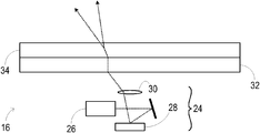
도 2를 다시 참조하면, 디스플레이 패널(14)은 광학 시스템(16)을 포함한다. 광학 시스템은 디스플레이 패널에 디스플레이 이미지를 형성하도록 구성된 전자 및 광학 컴포넌트의 조립품을 포함한다. 나아가, 광학 시스템은 전술한 바와 같은 강도 프로파일을 갖고 있는 빛을 사용하여 디스플레이 이미지를 형성할 수 있다. 도 2는 또한 광학 시스템(16)에 접속되어 동작하는 컴퓨터 시스템(18)을 도시한다. 컴퓨터 시스템은 디스플레이 이미지를 형성하기 위해 디스플레이 패널에 데이터를 제공하도록 구성될 수 있다. Referring again to FIG. 2,
몇몇 실시예에서, 광학 시스템(16)은 디스플레이 패널(14) 상에 또는 그 근처에 놓여 있는 사물들을 감지하도록 구성되는 이미징 스택(imaging stack)도 포함할 수 있다. 따라서, 컴퓨터 시스템은 이미징 스택으로부터 입력 데이터를 수신하도록 구성될 수 있다. 이런 식으로, 광학 시스템은 컴퓨터 시스템(18)을 위해 적어도 일부의 입력 기능을 제공할 수 있다. 도 2에 도시된 실시예에서, 컴퓨터 시스템은 디스플레이 패널(14) 아래에 있는 받침대(20) 안에 포함되고, 이것들을 합치면, 받침대와 디스플레이 패널은 콘솔(22)을 구성한다. 다른 실시예에서, 컴퓨터 시스템의 전체 또는 일부는 멀리 떨어져 배치되어 유선 또는 무선 통신 링크를 통해 광학 시스템에 접속되어 동작할 수 있다. 또 다른 실시예에서, 컴퓨터 시스템 및 광학 시스템 모두가 디스플레이 패널 안에 있을 수도 있다. In some embodiments,
도 4는 일 실시예에서 광학 시스템(16)의 양태들을 개략적으로 도시한다. 광학 시스템은 광원(26)이 배치된 이미지 프로젝터(24)를 포함한다. 일 실시예에서, 임의의 적절한 백색 광원 - 예컨대, 아크등(arc lamp), 백열등 또는 CCFL(cold-cathode fluorescent lamp)과 결합한 회전 프리즘(rotating prism) 또는 색상환(color wheel)과 같은 파장-선택 구성요소를 포함할 수 있다. 다른 실시예에서, 광원은 복수의 협대역 광원 - 예컨대, 레이저 또는 LED(light-emitting diode)를 포함할 수 있다. 4 schematically illustrates aspects of
이미지 프로젝터(24)는 또한 광원으로부터 빛을 수신하도록 배치된 이미지-형성 행렬(image-forming matrix)(28)을 포함한다. 이미지-형성 행렬은 공간적 및 시간적으로 빛을 변조하여 디스플레이 이미지를 형성하도록 구성된 임의의 적절한 컴포넌트일 수 있다. 도 4에 도시된 실시예에서, 이미지-형성 행렬은 광원으로부터의 파장-선택 광을 복수의 화소로 나누어, 이들 화소로부터의 일부 광을 선택적으로 이미징 옵틱(imaging optic)(30)으로 보내고 화소로부터의 나머지 광을 선택적으로 이미징 옵틱으로부터 멀리 보내는 DLP(digital light processing) 행렬이다. 다른 실시예는 복수 개의 협대역 광원으로부터의 빛을 수신하고 안내하도록 구성된 복수 개의 이미지-형성 행렬을 포함할 수도 있다. 또 다른 실시예에서, 이미지-형성 행렬은 컬러 필터와 짝을 이룬 광 밸브의 행렬을 포함할 수 있다. 이런 실시예에서, 이미지-형성 행렬은 화소들로부터의 부분 광을 선택적으로 전송하고, 화소들로부터의 나머지 광을 선택적으로 흡수하도록 구성되어, 이를 통해 디스플레이 이미지를 형성할 수 있다.
계속해서 도 4에서, 광학 시스템(16)은 콜리메이션 층(collimating layer)(32)을 포함한다. 콜리메이션 층은 이미지 프로젝터(24)로부터 빛을 수신하고 그 수신된 빛을 콜리메이션하도록 배치된 임의의 적절한 광학 층(optical layer)일 수 있다. 일 실시예에서, 콜리메이션 층은 고분자 필름(polymer film)에서 지원하는 프레넬 렌즈(Fresnel lens) 또는 프레넬-렌즈 어레이를 포함할 수 있다. 도 4에 도시된 실시예에서, 콜리메이션 층은 이미지 프로젝터(24)와 각도-확대층(34) 사이에 위치하여, 콜리메이션 층에서 수신된 빛을 콜리메이션된 형태로 각도-확대층으로 보내게 된다. 각도-확대층은 콜리메이션 층으로부터 콜리메이션된 빛을 수신하도록 배치되며, 이 빛을 바람직한 강도 프로파일(예컨대, 도 3에 도시된 강도 프로파일)로 재전송하도록 구성될 수 있다. 4, the
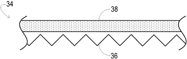
도 5는 예시적인 일 실시예에서 각도-확대층(34)의 수직 단면도를 개략적으로 도시한다. 각도-확대층은 마이크로 구조 굴절기(36) 및 산광기(38)를 포함한다. 마이크로 구조 굴절기는 제 1 강도 프로파일의 빛(예컨대, 콜리메이션 층(32)으로부터 콜리메이션된 빛)을 수신하도록 배치되고, 수신된 빛의 적어도 일부를 제 2 강도 파일로 전송하도록 구성된다. 5 schematically shows a vertical cross-sectional view of the angle-enlarging
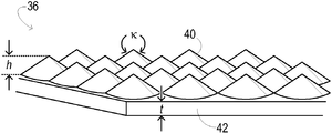
도 6은 마이크로 구조 굴절기(36)의 일 실시예를 보다 상세하게 도시한다. 도시된 실시예에서, 마이크로 구조 굴절기는 엑시콘 어레이(axicon array) - 즉, 육각형으로 타일링된 원뿔형 렌즈렛(conical lenslet) 어레이(40)를 포함한다. 피치(pitch), 및 그에 따른 어레이의 밀도는 본 개시의 여러 실시예마다 다를 수 있으며, 광학 시스템에 이미징 스택(아래를 참조)이 포함되었는지 여부에 의해 좌우될 수 있다. 특히, 선택된 피치는 디스플레이 컨텐츠에 나타나는 에일리어싱(aliasing)과 같은 아티팩트를 야기하지 않으면서, 이미징 스택을 최소한으로만 간섭하도록 충분히 작은 크기일 수 있다. 일 실시예에서, 마이크로 구조 굴절기는 평방 센티미터(㎠) 당 600 원뿔형 렌즈렛을 포함할 수 있다. 이런 렌즈렛 밀도는 디스플레이 화소 크기 d 정도의 피치를 제공하기에 적당하며, 여기서 d = 0.43 mm이고, 따라서, d = 0.43 mm일 때 320/㎠인 렌즈렛 밀도가 사용될 수 있다. 피치가 디스플레이 화소 크기의 1/3로 설정되는 실시예에서, 렌즈렛 밀도는 5000/㎠까지 높아질 수 있다. 6 illustrates one embodiment of the
일 실시예에서, 원뿔형 렌즈렛(40) 각각은 (원뿔의 임의의 두 모선 간의 최대각으로써 정의되는) 높이 h 및 조리개 κ를 갖고 있는 직원뿔(right circular cone)을 나타낸다. 특정한 일 실시예에서, h 는 0.46 mm이고, κ는 66.5도일 수 있다. 보다 일반적으로는, 희망하는 최종 광도 프로파일, 각도-확대층을 형성하는 물질의 굴절률, 및 산광기의 빛-확산력에 기반하여, 마이크로 구조 굴절기의 각종 구성요소에 대한 적절한 수치들이 결정될 수 있다. 이런 식으로, 마이크로 구조 굴절기는 수신하는 빛을 매우 효율적으로 재분배할 수 있다. In one embodiment, each of the
계속해서 도 6에서, 마이크로 구조 굴절기(36)의 원뿔형 렌즈렛들(40)은 기판층(substrate layer)(42) 상에 배치되거나, 기판층(42)에 의해 지지되고, 몇몇 예시에서는 기판층(42) 안에 형성될 수도 있다. 기판층은 임의의 적절한 두께 t를 가질 수 있다. 특정 실시예에서, 마이크로 구조 굴절기 전체(굴절 구성요소 및 기판층)는 미리 형성된 고분자 필름을 포함할 수 있다. 특정 일 실시예에서, 이런 필름은 산광기(38)에 적층될 수 있다. 도 6에 도시된 바와 같이, 원뿔형 렌즈렛들(40)의 꼭지점(apices)은 기판에서 멀어지는 쪽을 향한다. 보다 일반적으로, 마이크로 구조 굴절기의 임의의 굴절 구성요소의 꼭지점은 기판에서 멀어지는 쪽을 향할 수 있다. 6, the
마이크로 구조 굴절기(36)가 수신한 빛을 전송하는 제 2 강도 프로파일은 제 1 강도 프로파일보다 기판층(42)에 대해 수직으로 낮은 상대 강도를 가질 수 있다. 따라서, 제 1 강도 프로파일보다 기판층에 대해 경사진 방향으로는 높은 상대 강도를 가질 수 있다. 일 실시예에서, 제 2 강도 프로파일은 환형일 수 있다. 또한, 마이크로 구조 굴절기는 전송된 빛을 명확한 초점을 통해 보내고, 이런 특성은 주변광을 차단하는 디스플레이 패널의 기능을 향상시키기 위해 몇몇 실시예에서 이용될 수 있으며, 이는 이하에서 추가적으로 설명된다. The second intensity profile, which transmits the light received by the
이제 다시 도 5를 참조하면, 산광기(38)는 마이크로 구조 굴절기(36)에 의해 전송되는 빛을 수신하도록 배치되고, 수신된 빛의 적어도 일부를 제 3 강도 프로파일로 전송하도록 구성된 광학 층이다. 제 2 강도 프로파일이 환형인 실시예에서, 제 3 강도 프로파일은 확산하며 환형일 수 있다. 이런 식으로, 산광기를 빠져나오는 빛은 도 3에 도시된 것과 같은 강도 프로파일을 얻을 수 있으며, 여기서 디스플레이 패널(14)에 경사진 강도가 가장 강한 강도이다. 또한, 산광기는 각도-확대층(34)에 바람직한 주변광 차단 특성을 줄 수 있다. 이런 특성은 광학 시스템(16)의 여러 내부 구조를 효과적으로 감추고, 주변광원으로부터의 정반사(specular reflection)를 줄일 수 있다. 산광기(38)는 임의의 적절한 방식으로 마이크로 구조 굴절기(36)에 접속될 수 있으며, 예컨대, 마이크로 구조 굴절기에 필름 적층되거나(film laminated), 광학 접착제, 자외선(uv) 캐스트로 접합되거나, 또는 다중-시트 몰딩(multi-sheet molding)을 통해 형성될 수 있다. Referring now again to FIG. 5, the
도 5에 도시된 실시예에서, 산광기(38)는 복수의 굴절기 및/또는 광-산란 구성요소(light-scattering element)들이 삼차원 볼륨 안에 분포되어 있는 볼륨형(volume-type) 산광기이다. 일 실시예에서, 볼륨형 산광기는 그 안에 분포되고 고정된, 입자와 같은, 광 산란 구성요소의 제어된 밀도를 갖고 있는 유연한 필름(flexible film)을 포함할 수 있다. 이런 식으로 구성되어, 볼륨형 산광기는 헤니이-그린스타인(Henyey-Greenstein) 인자에 따라 수신된 빛의 강도 프로파일을 확대할 수 있고, 동일한 헤니이-그린스타인 인자에 의해 입사 주변광을 확산시킬 수도 있다. 이러한 볼륨형 산광기의 하나로 퓨전 옵틱스 코포레이션(Fusion Optix Corporation)의 제품 ADF4040(40도 FWHM 경우)이 있다. 다른 실시예에서, 볼륨형 산광기는 향상된 주변광 차단을 위해 제어된 양의 착색제(tinting agent)(즉, 염료 또는 기타 가시 광선 흡수 물질)를 포함할 수도 있다. 또 다른 실시예에서, 볼륨형 산광기는 추가적으로 정반사를 제한하고 주변광을 차단하기 위해, 거칠거나(roughened) 또는 딤플이 있는(dimpled) 윗면(즉, 시청자를 마주보는 표면)을 지원할 수 있다. In the embodiment shown in FIG. 5, the
도 7은 마이크로 구조 굴절기 및 볼륨형 산광기를 포함하는 다른 각도-확대층(44)의 수직 단면도를 개략적으로 도시한다. 도 7에 도시된 각도-확대층은 (전술한 바와 같은) 마이크로 구조 굴절기의 원뿔형 렌즈렛들이 볼륨형 산광기의 표면(즉, 시청자와 마주하지 않는 표면)에 직접 몰딩되므로 모놀리식(monolithic)으로 된다. 따라서, 산광기는 원뿔형 렌즈렛 또는 기타 굴절 구성요소들이 배치되는 바로 그 기판일 수 있다. 이런 구성요소들은 예를 들어, 압축 몰딩(compression molding)에 의해 각도-확대층에 형성될 수 있다. 일 실시예에서, 각도-확대층의 광-산란 구성요소들은 비균질적으로 분포할 수 있다 - 예컨대, 그곳에 형성된 원뿔형 렌즈렛들로부터 최소한 부분적으로는 분리될 수 있다. 7 schematically illustrates a vertical cross-sectional view of another angle-enlarging
도 8은 일 실시예에서 또 다른 각도-확대층(46)의 수직 단면도를 개략적으로 도시한다. 여기서, 복수의 굴절 및/또는 광-산란 구성요소들(48)이 기판층(42)의 표면 상에 배치되어, 표면-부조형 산광기(surface-relief type diffuser)(50)를 형성한다. 일 실시예에서 이런 광-확산 표면 요소(light-diffusing surface features)는 오목 또는 볼록 렌즈렛, 딤플, 또는 범프(bump)의 규칙적인 혹은 불규칙적인 어레이를 포함한다. 일 실시예에서, 표면 요소는 기판층(42)에 직접 몰딩될 수 있다. 적절한 몰딩 기법으로는 예로써, 열 몰딩(thermal molding) 및 uv-캐스팅을 들 수 있다. 다른 실시예에서, 이런 요소를 갖는 필름은 기판 층에 적층되고, 그 위에 (예컨대, 열-프레스 롤링(heat-press rolling)에 의해) 압연되거나, 스크린-인쇄를 통해 형성될 수 있다. 롤링 또는 스크린 인쇄를 통해 적용될 수 있는 표면 요소는 화이트 도트(white dot), 마이크로도트(microdot) 또는 확산 패드(diffusing pad)를 포함한다. 일 실시예에서, 이런 요소는 가시 광선을 확산시키지만, 적외선에서는 실질적으로 투명할 수 있다. 8 schematically illustrates a vertical cross-sectional view of another angle-enlarging
표면-부조형 산광기(50)는 이런 식으로 구성되어, 가우시안 인자에 따라 디스플레이 이미지 광의 강도 프로파일은 확대하고 동일한 가우시안 인자에 의해 주변광을 확산시킬 수 있다. 도 8에 도시된 실시예에서, 마이크로 구조 굴절기(36)는 산광기 맞은 편의 기판층(42)에 배치된다. 이런 표면-부조형 산광기의 하나로 캘리포니아 토렌스의 루미닛(Luminit)의 제품 L45E5 광 성형 산광기(Light Shaping Diffuser)(45 도 FWHM 각 스프레드(angular spread) 제공)가 있다. The surface-mounted
각도-확대층(46)에 의한 주변광 차단을 더욱 향상하기 위해, 불투명한 구성요소(51) 어레이가 광-확산 요소(48)와 함께 기판(42)에 배치된다. 도 8에 도시된 실시예에서, 마이크로 구조 굴절기의 원뿔형 렌즈렛의 초점(또는 착란원(circle of confusion))이 산광기(50)의 평면이나 그 근처에 있고 또한 인접한 불투명한 구성요소들 사이에 있도록, 불투명한 구성요소들은 마이크로 구조 굴절기(36)의 꼭지점에 맞춰 배치된다. 이러한 접근 방법을 통해 이들 지역을 조명하는 주변광을 흡수함으로써, 초점들 간의 주변광의 반사를 줄이면서 초점을 통한 디스플레이 광의 저-손실 전송이 가능해진다. 이론상으로는, 산광기의 투명-대-불투명 면적비 - 몇몇 실시예에서는 1:4와 동일한 인자값에 의해 전체 주변광 반사가 이런 식으로 감소될 수 있다. 따라서, 주변광 차단은 조명 강도의 저하 없이 뚜렷하게 향상될 수 있다. 이런 접근 방법은 마이크로 구조 굴절기의 꼭지점에 대한 불투명한 구성요소의 정확한 위치 결정을 필요로 한다. 이런 정확도는 패터닝된 마스킹 프로세스(patterned masking process)를 통해 얻을 수 있다. 마스크는 임의의 적절한 몰딩 프로세스 - 일례로, 셀프-얼라인(self-aligned) 조리개 마스킹 프로세스를 통해 형성될 수 있다. To further improve the blocking of ambient light by the angle-enlarging
일 실시예에서, 불투명한 구성요소들(51)은 검은색일 수 있다. 다른 실시예에서, 불투명한 구성요소들은 가시 광선에는 불투명하지만, 적외선에는 적어도 부분적으로는 투명할 수 있다. 이런 번형은 각도-확대층 위에 배치된 적외선-기반 이미징 스택을 포함하는 광학 시스템 실시예에 특히 적합하며, 이는 아래에서 설명될 것이다. In one embodiment, the
이들 또는 기타 실시예에서, 적절히 견고할 정도로(robust) 충분히 두껍게 각도-확대층(34)을 설계하는 것이 바람직하다. 균형을 유지하면서도 견고함을 증가시키기 위해, 각도-확대층은 터치 표면으로 기능할 수 있는 두꺼운 기판에 적층될 수 있지만, 이 기판의 두께는 터치 위치와 디스플레이 컨텐츠 위치 사이의 시차(parallax) 양을 제한하기 충분할 정도로 제한되어야 한다. 일례로, 고릴라 글래스(Gorilla Glass)(뉴욕, 코닝에 있는 코닝사(Corning, Inc.)의 제품)와 같이, 2에서 5 mm 두께의 화학적으로 경화된 유리 기판의 바닥면에 적층된 두께가 0.5에서 1 밀리미터(mm) 사이인 각도-확대층을 들 수 있다. 각도-확대층에 콜리메이션된 입력을 제공하기 위해 이 적층된 시트 아래에 프레넬 렌즈를 배치할 수 있다. 프레넬 렌즈는 렌즈 자체의 무게를 지탱하기에 충분히 두꺼운 시트에 몰딩되고, 적층된 각도-확대층은 맨 위 두꺼운 유리 기판에 의해 지지되어, 무게 및 떨어짐 충격에 처하게 될 때 충분히 큰 견고함을 제공할 수 있다. 윗면은 주변 반사를 줄이기 위해 반사 방지 필름으로 도포될 수 있다. 또한, 추가적인 내구성을 제공하기 위해 하드 코트(hard coat)가 추가되거나, 또는, 반사 방지 및 하드-코팅 추가 필름이 적층될 수 있다. 이런 시나리오에서, 디스플레이 패널 스택이 굴절 요소 어레이, 볼륨 산광기, 마스킹, 적층 접합(lamination bond), 및 유리 기판(반사 방지 코팅될 수 있음)을 포함하도록 주변 차단 마스킹 또한 사용될 수 있다. 이 경우에, 프레넬 렌즈는 디스플레이 패널 스택 아래에 공극(air gap)이 있게 배치되며, 디스플레이 패널 스택의 바닥을 향해 위쪽을 바라보는 프레넬 그루브(Fresnel groove)를 갖고 있는, 프레넬 렌즈는 두껍거나 또는 그 무게를 지지하고 처짐을 방지하기에 적당히 두꺼운 기판에 적층됨으로써 지지될 것이다. In these or other embodiments, it is desirable to design the angle-enlarging
전술한 실시예들 외에도 추가적인 실시예를 고려한다. 몇몇 실시예에서, 예를 들어, 각도-확대층은 확산기를 아예 포함하지 않을 수 있다. 적절하게 확산된(완전히 콜리메이션되지는 않은) 빛이 각도-확대층에서 수신될 때 또는 하나 이상의 광-확산 컴포넌트가 각도-확대층의 아래쪽에(downstream) 광학적으로 배치될 때, 이런 구성이 적합할 수 있다. 다른 실시예에서, 마이크로 구조 굴절기는 엑시콘 어레이 대신에 또는 액시콘 어레이에 추가하여 다른 굴절 구성요소들을 포함할 수 있다. 이에는 꼭지점이 둥글거나 꼭지점이 평평한 유사-원뿔형(pseudo-conical) 렌즈렛 어레이, 테이퍼드 마이크로 로드(tapered microrod) 어레이, 또는 이런 특징의 영역을 조명하는 빛이 각도 확장에 대비하도록 딤플 크기와 위치가 달라지는 제어된-딤플 어레이가 포함된다. 프로젝션 디스플레이 스크린의 경우에 관한 다른 일례에서, 굴절기 어레이의 피치는 디스플레이 화소 피치와 어레이 피치 간의 에일리어싱의 가능성을 줄이기 위해 유사-랜덤화될(pseudo-randomized) 수 있다. 또한, 엑시콘 어레이 대신에 일차원 어레이에서 둘 이상의 층의 정렬된 프리즘형 구성요소(prismatic element)가 사용될 수 있다. 일례로, 각도-확대층은 제 1 방향으로 정렬된 제 1 프리즘형 어레이와 제 1 방향에 직각인 제 2 방향으로 정렬된 제 2 프리즘형 어레이를 포함할 수 있다. 다른 예로, 각도-확대층은 서로 60도로 정렬된 제 1, 제 2, 및 제 3 프리즘형 어레이를 포함할 수도 있다. In addition to the embodiments described above, additional embodiments are contemplated. In some embodiments, for example, the angle-enlarging layer may not include a diffuser at all. This configuration is suitable when properly diffused (not fully collimated) light is received at the angle-enlarging layer or when one or more light-diffusing components are optically placed downstream of the angle-enlarging layer. can do. In other embodiments, the micro structure refractors may include other refractive components instead of or in addition to the axicon array. These include pseudo-conical lenslet arrays, tapered microrod arrays, or rounded vertices, or dimple sizes and positions so that light illuminating areas of this feature is ready for angular expansion. Included is a controlled-dimple array. In another example relating to the case of a projection display screen, the pitch of the refractor array can be pseudo-randomized to reduce the possibility of aliasing between the display pixel pitch and the array pitch. In addition, two or more layers of aligned prismatic elements in a one-dimensional array may be used instead of the excicon array. In one example, the angle-enlarging layer can include a first prismatic array aligned in a first direction and a second prismatic array aligned in a second direction perpendicular to the first direction. As another example, the angle-enlarging layer may include first, second, and third prismatic arrays that are aligned at 60 degrees to each other.
도 9는 일 실시예에서 예시적인 다른 광학 시스템(52)을 개략적으로 도시한다. 광학 시스템은 백라이트 엔벨로프(backlight envelope)(56) 안에 배치된 복수의 램프(54)를 포함한다. 램프는 예를 들어, 백열등, CCFL, 또는 LED를 포함할 수 있다. 백라이트 엔벨로프는 한쪽 면(예컨대, 도면에서는 윗면)에 빛이 빠져 나오는 하나 이상의 개구부를 포함할 수 있다. 또한 백라이트 엔벨로프는 빠져나오지 못한 빛이 재사용되도록 적어도 부분적으로는 반사 내면을 포함할 수도 있다. 산광기(58)는 백라이트 엔벨로프의 개구면에 접속된 것으로 도시된다. 산광기의 광-확산력은 백라이트 엔벨로프의 개구면에 균일한 조명을 제공하기에 충분할 수 있으며, 산광기에서 나오는 빛은 가우시안 강도 프로파일을 가질 수 있다. 9 schematically illustrates another exemplary
도 9에 도시된 실시예에서, 제 1 각도-제한층(angle-limiting layer)(60)이 산광기(58)에 접속되고, 제 2 각도-제한층(62)은 제 1 각도-제한층에 접속된다. 제 1 및 제 2 각도-제한층은 각각 각도 범위 내에서 입사하는 빛을 전송하고, 각도 범위 밖에서 입사하는 빛을 반사하도록 구성될 수 있다. 일 실시예에서, 제 1 및 제 2 각도 제한층은 각각 프리즘형 마이크로- 또는 밀리 구조(prismatic micro- or millistructure)를 갖는 층을 포함할 수 있다. 제 1 각도-제한층의 프리즘형 구성요소는 제 1 방향을 향하고, 제 2 각도-제한층의 프리즘형 구성요소는 제 1 방향에 직각인 제 2 방향을 향할 수 있다. 나아가, 전송된 빛이 제한되는 입사각의 범위는 제 1 및 제 2 각도-제한층에서 같거나 다를 수 있다. 이런 식으로, 제 1 및 제 2 각도-제한층은 등방성 또는 이방성 강도 프로파일을 전송하도록 구성될 수 있다. 일 실시예에서, 제 1 및/또는 제 2 각도-제한층은 빛을 재사용하는 BEF(brightness enhancing film)를 포함할 수 있고, 예컨대, BEF는 전송된 빛의 프로파일을 40도에서 50도의 출구 원뿔(exit cone)로 제한할 수 있다. 다른 실시예에서는, 반면, 각도-제한층을 생략함으로써, 더 큰 시야각에서 증가된 강도를 얻을 수 있다. In the embodiment shown in FIG. 9, a first angle-limiting
도 9에 도시된 실시예에서, 광학 시스템(52)은 또한 이미징 스택(64)을 포함한다. 이미징 스택은 디스플레이 패널(14) 상에 또는 그 위에 배치된 하나 이상의 사물을 이미지화하도록 구성된 전자 및 광학 컴포넌트의 조립품을 포함할 수 있다. 이런 사물로는 손가락 또는 스타일러스(stylus)를 포함할 수 있고, 사물을 이미지화함으로써 컴퓨터 시스템(예컨대, 도 1의 컴퓨터 시스템(18))을 위한 터치- 또는 사물-감지 입력 메커니즘을 가능하게 할 수 있다. 이미징 스택은 광학 시스템(52)의 백라이트 위에 배치되어, 특히, 디스플레이 패널의 표면에 수직으로 높은 가시 투명도(visible transparency)를 갖도록 구성될 수 있다. 따라서, 이미징 스택은 협대역 적외선 광원(도면에 도시되지 않음)을 이용할 수 있고, 디스플레이 패널 상에 또는 그 근처에 있는 사물로부터 반사된 적외선을 이미지화하도록 구성될 수 있다. 도 9에 도시된 특정 실시예에서, 웨지형 광 가이드(wedge-shaped light guide)(66)는 디스플레이 패널의 시야면 맞은 편에 있는 이색성 터닝 필름(dichroic turning film) 및 미러 단면(mirrored end face)을 지원한다. 이런 구조는 반사된 적외선을 사물이 이미지화되는 카메라(68)로 집중시킨다. 하지만, 기타 상당히 다른 이미징 스택도 동등하게 고려되며, 그 중 일부는 오프셋-이미징 접근 방법(offset-imaging approach)을 이용할 수도 있음을 이해할 것이다. 이런 실시예에서, 이미징 스택은 디스플레이 이미지를 형성하기 위한 가시 광선을 전송하면서, 입력 이미지와 관련된 적외선을 반사할 수 있다. In the embodiment shown in FIG. 9,
계속해서 도 9에서, 광학 시스템(52)은 이미징 스택(62) 위에 배치되고 대체로 전술한 바와 같이 구성되는 각도-확대층(46)을 포함한다. 또한, 광학 시스템은 각도-확대층으로부터 빛을 수신하여 그 빛을 공간적 및 시간적으로 변조하여 디스플레이 이미지를 형성하도록 배치된 이미지-형성 행렬(70)을 포함한다. 일 실시예에서, 이미지-형성 행렬은 복수의 광 밸브 - 예컨대, LCD(liquid-crystal display) 행렬을 포함한다. 광학 시스템은, 주변광을 산란시키고 광학 시스템의 구조적인 컴포넌트들을 마스킹하면서, 이미지-형성층에 접속하여 디스플레이 이미지를 전송하도록 구성된 산광기(72)도 포함한다. 9, the
다른 실시예 역시 고려된다. 일 실시예에서, 각도-확대층 또는 각도-확대층들은 백라이트 조립품의 각도-제한층 또는 각도-제한층들 위에 직접 배치될 수 있다. 여기서, 이미징 스택은 디스플레이 패널의 윗면 또는 바닥면에 아주 근접하여 적층된 산광기와 함께 사용될 수 있고, 나아가 산광기는 PDLC(polymer dispersed liquid crystal)과 같은 스위칭 가능한 산광기를 포함할 수 있다. 이 경우에, 디스플레이 패널 위에 적외선 조명을 제공하기 위해 광-가이드 기반 프론트라이트(frontlight)(도면에 도시되지 않음)가 포함될 수 있다. 또는, 이미징 스택이 생략되거나, 이미징 스택이 이른바 SIP(sensor-in-pixel) 기술을 사용하여 이미지-형성 행렬에 통합될 수 있다. 이와 같은 경우에, 각도-확대층은 백라이트 유닛 위에 놓여지고, 산광기 또는 산광기 층들은 SIP 패널 바로 아래에 배치될 수 있다. 다른 실시예에서, 각도-확대층은 백라이트 조립품 바로 위에 배치되고, 제 1 및 제 2 각도-제한층은 생략될 수 있다. 이런 구성은 디스플레이 패널 법선에 대해 더 큰 시야각에서 제공되는 광도를 더욱 증가시킬 것이다. 또 다른 일 실시예에서, BEF 필름이 희망하는 40도에서 50도 스프레드 내의 백라이트의 광 출력을 포함하기 위해 사용될 때, BEF 출력이 산광기에서 제공될 희망하는 각 스프레드(angular spread)와 비슷하기 때문에, 산광기는 시각 시스템에서 없을 수 있다. 이런 실시예는 희망하는 광도 프로파일을 제공하기 위해 엑시콘 어레이 또는 두 개 또는 세 개가 교차된, 일차원 프리즘형 어레이를 포함할 수 있다. Other embodiments are also contemplated. In one embodiment, the angle-enlarging layer or angle-enlarging layers may be disposed directly over the angle-limiting layer or angle-limiting layers of the backlight assembly. Here, the imaging stack can be used with diffusers stacked very close to the top or bottom surface of the display panel, and further, the diffuser can include a switchable diffuser such as a polymer dispersed liquid crystal (PDLC). In this case, a light-guide based frontlight (not shown in the figure) may be included to provide infrared illumination over the display panel. Alternatively, the imaging stack may be omitted or the imaging stack may be integrated into an image-forming matrix using so-called sensor-in-pixel (SIP) technology. In such a case, the angle-enlarging layer is placed over the backlight unit and the diffuser or diffuser layers can be placed directly below the SIP panel. In another embodiment, the angle-enlarging layer is disposed directly above the backlight assembly, and the first and second angle-limiting layers can be omitted. This configuration will further increase the brightness provided at larger viewing angles relative to the display panel normals. In another embodiment, when the BEF film is used to include the light output of the backlight within the desired 40 to 50 degree spread, because the BEF output is similar to the desired angular spread to be provided in the diffuser The diffuser may not be present in the vision system. Such an embodiment may include an excimon array or two or three crossed one-dimensional prismatic arrays to provide a desired brightness profile.
또한, 적외선 이미징 조명뿐만 아니라 가시 디스플레이 광선을 위해 LED 어레이가 사용될 때, 엑시콘 어레이 및/또는 교차된 프리즘형 어레이의 스택을 사용하여 높은 각도 편향을 얻을 수 있고, 어느 정도 떨어진 산광기를 사용하여 SIP/LCD 패널 바로 아래에 배치된 공동(cavity)를 감출 수 있다.In addition, when LED arrays are used for visible display light as well as infrared imaging illumination, high angle deflections can be achieved using stacks of excimon arrays and / or crossed prismatic arrays, It is possible to hide cavities disposed directly below the SIP / LCD panel.
마지막으로, 본원에서 설명된 물건, 시스템 및 방법은 예시를 위한 것으로, 많은 변형이 가능하므로 이들 구체적인 실시예나 예시들은 제한적인 것으로 여겨져서는 안 된다는 점을 이해할 것이다. 따라서, 본 개시는 본원에 개시된 다양한 시스템 및 방법의 모든 신규하고 비자명한 조합 및 서브컴비네이션(subcombination)은 물론, 임의의 모든 균등물도 포함한다Finally, it is to be understood that the objects, systems, and methods described herein are for illustrative purposes, and that many specific modifications are possible and these specific embodiments or examples should not be considered as limiting. Thus, the present disclosure includes all novel and non-combination combinations and subcombinations of the various systems and methods disclosed herein, as well as any equivalents.
Claims (15)
An array of refractive elements disposed on a substrate and configured to receive light of a first intensity profile and to transmit at least a portion of the received light to a second intensity profile, the second intensity profile compared to the first intensity profile A display panel having a lower relative strength perpendicular to the substrate and a higher relative strength in a direction inclined to the substrate.
상기 디스플레이 패널은
상기 굴절 요소 어레이에 의해 전송되는 상기 빛을 수신하도록 배치되고, 상기 수신된 빛의 적어도 일부를 제 3 강도 프로파일로 전송하도록 구성되는 산광기를 더 포함하는 디스플레이 패널.
The method of claim 1,
The display panel
And a diffuser arranged to receive the light transmitted by the array of refractive elements and configured to transmit at least a portion of the received light in a third intensity profile.
상기 기판에 대해 경사진 강도는 상기 제 3 강도 프로파일의 최대 강도인 디스플레이 패널.
The method of claim 1,
The inclined intensity relative to the substrate is the maximum intensity of the third intensity profile.
상기 굴절 요소 어레이는 복수의 꼭지점을 포함하고, 상기 꼭지점들은 상기 기판에서 멀어지는 쪽을 향하는 디스플레이 패널.
The method of claim 1,
And said array of refractive elements comprises a plurality of vertices, said vertices facing away from said substrate.
상기 굴절 요소 어레이는 둘 이상의 프리즘형 어레이를 포함하는 디스플레이 패널.
The method of claim 1,
And the refractive element array comprises two or more prismatic arrays.
상기 굴절 요소 어레이는 원뿔형 렌즈렛 어레이를 포함하는 디스플레이 패널.
The method of claim 1,
And the refractive element array comprises a conical lenslet array.
상기 원뿔형 렌즈렛 어레이는 육각형으로 타일링된 디스플레이 패널.
The method according to claim 6,
Wherein the array of conical lenslets is tiled in a hexagon.
상기 산광기는 상기 산광기의 볼륨 내에 분포된 복수의 굴절 및/또는 광-산란 요소를 포함하는 디스플레이 패널.
The method of claim 1,
Wherein the diffuser comprises a plurality of refractive and / or light-scattering elements distributed within the volume of the diffuser.
상기 산광기는 복수의 굴절 및/또는 광-산란 요소가 배치된 표면층을 포함하는 디스플레이 패널.
The method of claim 1,
The diffuser includes a surface layer on which a plurality of refractive and / or light-scattering elements are disposed.
상기 산광기는 하나 이상의 착색제 및 불투명 요소 어레이를 더 포함하는 디스플레이 패널.
The method of claim 1,
The diffuser further comprises an array of one or more colorants and opaque elements.
상기 산광기는 상기 굴절 요소 어레이가 배열된 상기 기판인 디스플레이 패널.
The method of claim 1,
And the diffuser is the substrate on which the array of refractive elements is arranged.
상기 기판 및 상기 굴절 요소 어레이는 필름을 포함하는 디스플레이 패널.
The method of claim 1,
And the substrate and the array of refractive elements comprise a film.
상기 필름은 상기 산광기에 적층되는 디스플레이 패널.
13. The method of claim 12,
And the film is laminated to the diffuser.
상기 디스플레이 패널은
이미지 프로젝터 및 콜리메이션 층을 더 포함하고,
상기 콜리메이션 층은 상기 이미지 프로젝터와 상기 굴절 요소 어레이 사이에 배치되며, 상기 콜리메이션 층으로부터의 빛이 상기 굴절 요소 어레이에서 수신되는 디스플레이 패널.
The method of claim 1,
The display panel
Further comprising an image projector and a collimation layer,
Wherein the collimation layer is disposed between the image projector and the array of refractive elements, wherein light from the collimation layer is received at the array of refractive elements.
상기 디스플레이 패널은
광 밸브를 더 포함하고,
상기 굴절 요소 어레이 또는 상기 산광기로부터 전송되는 빛이 상기 광 밸브에서 수신되는 디스플레이 패널.15. The method of claim 14,
The display panel
Further comprising a light valve,
Display panel wherein light transmitted from the array of refractive elements or the diffuser is received at the light valve.
Applications Claiming Priority (3)
| Application Number | Priority Date | Filing Date | Title |
|---|---|---|---|
| US12/752,741 | 2010-04-01 | ||
| US12/752,741 US20110241977A1 (en) | 2010-04-01 | 2010-04-01 | Enhanced viewing brightness for surface display |
| PCT/US2011/030295 WO2011123429A2 (en) | 2010-04-01 | 2011-03-29 | Enhanced viewing brightness for surface display |
Publications (1)
| Publication Number | Publication Date |
|---|---|
| KR20130018726A true KR20130018726A (en) | 2013-02-25 |
Family
ID=44709022
Family Applications (1)
| Application Number | Title | Priority Date | Filing Date |
|---|---|---|---|
| KR1020127025438A KR20130018726A (en) | 2010-04-01 | 2011-03-29 | Enhanced viewing brightness for surface display |
Country Status (6)
| Country | Link |
|---|---|
| US (1) | US20110241977A1 (en) |
| EP (1) | EP2553521A4 (en) |
| JP (1) | JP2013524278A (en) |
| KR (1) | KR20130018726A (en) |
| CN (1) | CN102822730A (en) |
| WO (1) | WO2011123429A2 (en) |
Families Citing this family (6)
| Publication number | Priority date | Publication date | Assignee | Title |
|---|---|---|---|---|
| JP5545068B2 (en) * | 2010-06-25 | 2014-07-09 | ソニー株式会社 | Light source device and stereoscopic display device |
| TWI511003B (en) * | 2011-12-05 | 2015-12-01 | Wistron Corp | Optical touch device and frame thereof |
| US8717660B2 (en) | 2012-07-03 | 2014-05-06 | Qualcomm Mems Technologies, Inc. | Annulus scattering diffuser for reflective display |
| US9387651B2 (en) | 2012-09-26 | 2016-07-12 | Corning Incorporated | Methods for producing ion exchanged glass and resulting apparatus |
| US20140087193A1 (en) * | 2012-09-26 | 2014-03-27 | Jeffrey Scott Cites | Methods for producing ion exchanged glass and resulting apparatus |
| EP3234920A4 (en) * | 2014-12-23 | 2017-10-25 | Meta Company | Apparatuses, methods and systems coupling visual accommodation and visual convergence to the same plane at any depth of an object of interest |
Family Cites Families (27)
| Publication number | Priority date | Publication date | Assignee | Title |
|---|---|---|---|---|
| DE2651219C3 (en) * | 1976-11-10 | 1980-11-13 | Minox Gmbh, 6300 Giessen | Viewing device for film originals |
| JPH0695112A (en) * | 1992-09-16 | 1994-04-08 | Hitachi Ltd | Prism plate and information display device formed by using this plate |
| JP2599121Y2 (en) * | 1993-05-07 | 1999-08-30 | 株式会社エンプラス | Surface light source device |
| US5563738A (en) * | 1993-09-03 | 1996-10-08 | Jenmar Visual Systems | Light transmitting and dispersing filter having low reflectance |
| IL112070A0 (en) * | 1993-12-21 | 1995-03-15 | Minnesota Mining & Mfg | Optical display |
| JPH10293212A (en) * | 1997-02-18 | 1998-11-04 | Dainippon Printing Co Ltd | Backlight and liquid crystal display device |
| JPH11271765A (en) * | 1998-01-26 | 1999-10-08 | Mitsubishi Chemical Corp | Surface light source unit |
| JPH11258698A (en) * | 1998-03-11 | 1999-09-24 | Omron Corp | Image display device and light diffusion sheet |
| JP3271660B2 (en) * | 1999-01-19 | 2002-04-02 | 恵和株式会社 | Light path control diffusion sheet and backlight unit using the same |
| US6624934B1 (en) * | 1999-06-18 | 2003-09-23 | 3M Innovative Properties Company | Projection screen using variable power lenticular lens for asymmetric viewing angle |
| JP2002139729A (en) * | 2000-10-31 | 2002-05-17 | Sony Corp | Liquid crystal display device |
| JP2002267812A (en) * | 2001-03-13 | 2002-09-18 | Daicel Chem Ind Ltd | Light scattering film and liquid crystal display device using the same |
| JP2003121609A (en) | 2001-10-11 | 2003-04-23 | Hitachi Ltd | Optical sheet and display device equipped with the same |
| TWI258023B (en) * | 2001-11-07 | 2006-07-11 | Ibm | A prism sheet, a back-light unit using said prism sheet, and a transmission type liquid crystal display device |
| KR100897745B1 (en) * | 2002-06-26 | 2009-05-15 | 삼성전자주식회사 | Back light assembly and direct type liquid crystal display |
| CN100373176C (en) * | 2002-08-30 | 2008-03-05 | 木本股份有限公司 | Light control film |
| JP4225132B2 (en) * | 2003-06-24 | 2009-02-18 | カシオ計算機株式会社 | Liquid crystal display |
| WO2005083475A1 (en) * | 2004-02-26 | 2005-09-09 | Takiron Co., Ltd. | Light diffusing sheet, and backlight unit using this light diffusing sheet |
| KR20060016518A (en) * | 2004-08-18 | 2006-02-22 | 삼성전자주식회사 | Display apparatus |
| US20060182409A1 (en) * | 2005-02-11 | 2006-08-17 | Eastman Kodak Company | Optical films of differing refractive indices |
| JP4977021B2 (en) * | 2005-06-24 | 2012-07-18 | 出光興産株式会社 | Light diffusing plate and lighting device using the same |
| EP1929361A4 (en) * | 2005-08-27 | 2009-10-21 | 3M Innovative Properties Co | Illumination assembly and system |
| US7466373B2 (en) * | 2006-01-03 | 2008-12-16 | Polytronix, Inc. | Flat panel displays with primary viewing envelopes away from displyay panel normal |
| JP4923671B2 (en) * | 2006-03-29 | 2012-04-25 | ソニー株式会社 | Liquid crystal display |
| DE102008021721A1 (en) * | 2007-05-08 | 2008-11-27 | Citizen Electronics Co., Ltd., Fujiyoshida-shi | Optical component, backlight unit and display device |
| US8848132B2 (en) * | 2008-02-07 | 2014-09-30 | 3M Innovative Properties Company | Hollow backlight with structured films |
| US8177382B2 (en) * | 2008-03-11 | 2012-05-15 | Cree, Inc. | Apparatus and methods for multiplanar optical diffusers and display panels for using the same |
-
2010
- 2010-04-01 US US12/752,741 patent/US20110241977A1/en not_active Abandoned
-
2011
- 2011-03-29 WO PCT/US2011/030295 patent/WO2011123429A2/en active Application Filing
- 2011-03-29 CN CN2011800178757A patent/CN102822730A/en active Pending
- 2011-03-29 JP JP2013502744A patent/JP2013524278A/en active Pending
- 2011-03-29 KR KR1020127025438A patent/KR20130018726A/en not_active Application Discontinuation
- 2011-03-29 EP EP11763314.9A patent/EP2553521A4/en not_active Withdrawn
Also Published As
| Publication number | Publication date |
|---|---|
| WO2011123429A3 (en) | 2012-01-26 |
| EP2553521A2 (en) | 2013-02-06 |
| JP2013524278A (en) | 2013-06-17 |
| CN102822730A (en) | 2012-12-12 |
| EP2553521A4 (en) | 2017-11-22 |
| US20110241977A1 (en) | 2011-10-06 |
| WO2011123429A2 (en) | 2011-10-06 |
Similar Documents
| Publication | Publication Date | Title |
|---|---|---|
| US8408721B2 (en) | Projection system with imaging light source module | |
| US8177408B1 (en) | Light filtering directional control element and light fixture incorporating the same | |
| US6995907B2 (en) | Diffusion sheet for use in transmission-type screen and transmission-type screen | |
| US20180203338A1 (en) | Illumination Device, Illumination Method, and Video Projection Apparatus Using the Same | |
| JP4713583B2 (en) | Projection screen device and projection television system | |
| KR20130018726A (en) | Enhanced viewing brightness for surface display | |
| WO2016092724A1 (en) | Headup display and mobile body provided with same | |
| CN107003557A (en) | Direct viewing type display device and the light unit for direct viewing type display device | |
| KR20040014358A (en) | Fresnel lens sheet and rear projection screen including the same | |
| TW201610553A (en) | High contrast rear projection screen for use with a diverging illumination source | |
| US20230288724A1 (en) | Aerial floating image information display system and light source apparatus used in the same | |
| JP5003298B2 (en) | Optical sheet, backlight unit using the same, and display device | |
| WO2021078289A1 (en) | Projection screen | |
| JP2006301430A (en) | Transmissive screen and projection type display apparatus | |
| JP2009080357A (en) | Light control sheet, backlight unit using the same, and display device | |
| JP2010266611A (en) | Optical equalizing element, optical sheet, backlight unit and display device | |
| KR100743670B1 (en) | Rear projection screen | |
| JP4103734B2 (en) | Video display device | |
| US6807020B2 (en) | Lens optimization and color correction for image projection systems | |
| JP2006349834A (en) | Diffusion plate for transmission type screen, transmission type screen and rear projection type display device | |
| US20110037923A1 (en) | Light condensing film, backlight module and liquid crystal display | |
| JP2016212294A (en) | Display | |
| JP2007293171A (en) | Reflection type projection screen and video display apparatus | |
| TW200304579A (en) | Micro-lens sheet and projection screen | |
| JP2002207253A (en) | Light-diffusion sheet and back projection type screen |
Legal Events
| Date | Code | Title | Description |
|---|---|---|---|
| N231 | Notification of change of applicant | ||
| WITN | Application deemed withdrawn, e.g. because no request for examination was filed or no examination fee was paid |