KR20130018666A - Expandable lamina spinal fusion implant - Google Patents
Expandable lamina spinal fusion implant Download PDFInfo
- Publication number
- KR20130018666A KR20130018666A KR1020127022692A KR20127022692A KR20130018666A KR 20130018666 A KR20130018666 A KR 20130018666A KR 1020127022692 A KR1020127022692 A KR 1020127022692A KR 20127022692 A KR20127022692 A KR 20127022692A KR 20130018666 A KR20130018666 A KR 20130018666A
- Authority
- KR
- South Korea
- Prior art keywords
- implant
- circlip
- anchor
- socket
- core
- Prior art date
Links
Images


Classifications
-
- A—HUMAN NECESSITIES
- A61—MEDICAL OR VETERINARY SCIENCE; HYGIENE
- A61B—DIAGNOSIS; SURGERY; IDENTIFICATION
- A61B17/00—Surgical instruments, devices or methods, e.g. tourniquets
- A61B17/56—Surgical instruments or methods for treatment of bones or joints; Devices specially adapted therefor
- A61B17/58—Surgical instruments or methods for treatment of bones or joints; Devices specially adapted therefor for osteosynthesis, e.g. bone plates, screws, setting implements or the like
- A61B17/68—Internal fixation devices, including fasteners and spinal fixators, even if a part thereof projects from the skin
- A61B17/70—Spinal positioners or stabilisers ; Bone stabilisers comprising fluid filler in an implant
- A61B17/7062—Devices acting on, attached to, or simulating the effect of, vertebral processes, vertebral facets or ribs ; Tools for such devices
- A61B17/7065—Devices with changeable shape, e.g. collapsible or having retractable arms to aid implantation; Tools therefor
-
- A—HUMAN NECESSITIES
- A61—MEDICAL OR VETERINARY SCIENCE; HYGIENE
- A61B—DIAGNOSIS; SURGERY; IDENTIFICATION
- A61B17/00—Surgical instruments, devices or methods, e.g. tourniquets
- A61B17/56—Surgical instruments or methods for treatment of bones or joints; Devices specially adapted therefor
- A61B17/58—Surgical instruments or methods for treatment of bones or joints; Devices specially adapted therefor for osteosynthesis, e.g. bone plates, screws, setting implements or the like
- A61B17/68—Internal fixation devices, including fasteners and spinal fixators, even if a part thereof projects from the skin
- A61B17/84—Fasteners therefor or fasteners being internal fixation devices
- A61B17/86—Pins or screws or threaded wires; nuts therefor
-
- A—HUMAN NECESSITIES
- A61—MEDICAL OR VETERINARY SCIENCE; HYGIENE
- A61F—FILTERS IMPLANTABLE INTO BLOOD VESSELS; PROSTHESES; DEVICES PROVIDING PATENCY TO, OR PREVENTING COLLAPSING OF, TUBULAR STRUCTURES OF THE BODY, e.g. STENTS; ORTHOPAEDIC, NURSING OR CONTRACEPTIVE DEVICES; FOMENTATION; TREATMENT OR PROTECTION OF EYES OR EARS; BANDAGES, DRESSINGS OR ABSORBENT PADS; FIRST-AID KITS
- A61F2/00—Filters implantable into blood vessels; Prostheses, i.e. artificial substitutes or replacements for parts of the body; Appliances for connecting them with the body; Devices providing patency to, or preventing collapsing of, tubular structures of the body, e.g. stents
- A61F2/02—Prostheses implantable into the body
- A61F2/30—Joints
- A61F2/44—Joints for the spine, e.g. vertebrae, spinal discs
Landscapes
- Health & Medical Sciences (AREA)
- Orthopedic Medicine & Surgery (AREA)
- Life Sciences & Earth Sciences (AREA)
- Neurology (AREA)
- Surgery (AREA)
- Engineering & Computer Science (AREA)
- Biomedical Technology (AREA)
- General Health & Medical Sciences (AREA)
- Veterinary Medicine (AREA)
- Heart & Thoracic Surgery (AREA)
- Public Health (AREA)
- Animal Behavior & Ethology (AREA)
- Molecular Biology (AREA)
- Medical Informatics (AREA)
- Nuclear Medicine, Radiotherapy & Molecular Imaging (AREA)
- Cardiology (AREA)
- Oral & Maxillofacial Surgery (AREA)
- Transplantation (AREA)
- Vascular Medicine (AREA)
- Prostheses (AREA)
- Surgical Instruments (AREA)
Abstract
확장 가능한 추간 임플란트는 미부 고정기 본체 및 미부 고정기 본체로부터 종방향 상방으로 연장하는 소켓을 포함하는 미부 고정기, 두부 고정기 본체 및 두부 고정기 본체로부터 종방향 하방으로 연장하는 코어를 포함하는 두부 고정기, 및 두부 고정기에 대한 미부 고정기의 종방향 위치를 고정시키도록 구성된 서클립을 포함한다. 코어는 외측 연장 두부 걸림 리지를 포함할 수 있고, 소켓 내로 끼워지도록 구성될 수 있다. 서클립은 내측 연장 서클립 걸림 리지를 포함할 수 있고, 소켓 내부에 끼워지도록 구성될 수 있다. 임플란트는 척추들의 추궁판에 임플란트를 부착함으로써 척추 운동 분절의 척추들 사이의 추간 공간 내로 설치되도록 구성될 수 있다. 임플란트는 임플란트가 척추들의 극돌기들 사이에서 연장하도록, 척추 운동 분절 내로의 설치 후에 확장되도록 구성될 수 있다.The expandable intervertebral implant includes a head anchorage comprising a tail anchor body and a socket extending longitudinally upward from the tail anchor body, a head anchorage comprising a head anchorage body and a core extending longitudinally downward from the head anchorage body. And a circlip configured to fix the longitudinal position of the tail anchor with respect to the head anchor. The core may include an outer extending head locking ridge and may be configured to fit into the socket. The circlip may include an inner extending circlip engagement ridge and may be configured to fit inside the socket. The implant may be configured to be installed into the intervertebral space between the vertebrae of the spinal motion segment by attaching the implant to the plaque of the vertebrae. The implant may be configured to expand after installation into the spinal motion segment, such that the implant extends between the spinous processes of the vertebrae.
Description
관련 출원에 대한 상호 참조Cross-reference to related application
본 출원은 본원에 전체적으로 설명되어 참조로 통합된 2010년 3월 4일자로 출원된 미국 가특허 출원 제61/310,492호에 기초하여 우선권을 주장한다.This application claims priority based on US
척추체의 퇴행성 디스크 질환 또는 퇴행은 흔히 디스크 높이의 소실을 일으키고, 이는 결국 통증 또는 염증 반응을 생성할 수 있는 다른 질환들 중에서도, 후관절-신경 충돌을 야기할 수 있다.Degenerative disc disease or degeneration of the vertebral body often leads to a loss of disc height, which can lead to facet-nerve collisions, among other disorders that may eventually produce pain or an inflammatory response.
종래의 후방 요추 융합술은 전형적으로 경추궁판 나사 또는 척추경 나사 고정술을 사용하여 수행된다. 나사 진입 지점을 제공하기 위한 척추경의 준비는 광범위하게 침습적이다. 예를 들어, 기립근이 전형적으로 척추 분절로부터 절제되어, 척추 부위의 생리학적 완결성을 훼손한다. 척추경의 준비는 또한 환자가 상당한 잔류 수술후 통증을 경험하게 할 수 있다.Conventional posterior lumbar fusion is typically performed using cervical plaque screw or pedicle screw fixation. Preparation of the pedicle to provide a screw entry point is widely invasive. For example, the standing muscles are typically excised from spinal segments, which compromises the physiological integrity of the spinal region. Preparation of the pedicle can also cause the patient to experience significant residual postoperative pain.
또한, 척추의 외과적 고정술이 퇴행성 상태와 관련된 즉각적인 통증 및 증후군을 경감시키는데 효과적일 수 있지만, 외과적 고정술은 퇴행 과정을 제거하거나 정지시키지 않는다. 결과적으로, 이후의 외과적 시술이 계속되는 퇴행을 해결하기 위해 필요해질 수 있다. 그러나, 후방 요추 고정술을 위한 척추경으로의 척추경 나사의 고정은 척추경이 이후의 재건 치료에 대해 생체 역학적으로 훼손되게 할 수 있다. 결과적으로, 이후의 더 광범위하고 침습적인 시술은 흔히 시멘트 보강, 골 형성 단백질(BMP)의 도포, 대형 척추경 나사 등을 포함한다.In addition, while surgical fixation of the spine may be effective in alleviating immediate pain and syndrome associated with a degenerative condition, surgical fixation does not eliminate or stop the degenerative process. As a result, subsequent surgical procedures may be needed to resolve the continued degeneration. However, fixation of the pedicle screw into the pedicle for posterior lumbar fixation can cause the pedicle to be biomechanically compromised for subsequent reconstruction treatment. As a result, subsequent more extensive and invasive procedures often include cement reinforcement, application of bone morphogenetic protein (BMP), large pedicle screws, and the like.
요추 융합술을 수행하는 다른 방법은 분절 강성을 유지하기 위해 전방 척추 체간 스페이서의 삽입을 포함하는, 경추궁판 나사의 적용을 포함한다. 경추궁판 나사가 후관절을 차단할 수 있지만, 이러한 방법은 문헌[Mueller ME: Manual of internal fixation: techniques recommended by the AO-ASIF Group, 3rd issue 1991, page 660ff]에 설명되어 있는 바와 같이, 환자 운동이 척추가 연신되게 하면, 운동 분절의 약간의 개방을 여전히 허용한다. 문헌[Oxland TR, Lund T. Biomechanics of stand-alone cages and cages in combination with posterior fixation: a literature review. Eur Spine J. 2000; 9 Suppl 1 :S95-101]에 설명되어 있는 바와 같이, 경추궁판 나사 고정술은 추간 공간의 좌굴을 감소시키거나 회피하기 위해, ALIF Cage와 같은 추간 스페이서와 조합될 수 있다.Another method of performing lumbar fusion involves the application of a cervical spinal disc screw, including the insertion of an anterior vertebral interbody spacer to maintain segment stiffness. Although cervical plaque screws may block the posterior joint, this method is described in the manual, as described in Mueller ME: Manual of internal fixation: techniques recommended by the AO-ASIF Group, 3 rd issue 1991, page 660ff. If exercise causes the spine to stretch, it still allows some opening of the motor segment. Oxland TR, Lund T. Biomechanics of stand-alone cages and cages in combination with posterior fixation: a literature review. Eur Spine J. 2000; As described in 9 Suppl 1: S95-101, cervical plaque screw fixation can be combined with an intervertebral spacer such as an ALIF cage to reduce or avoid buckling of the intervertebral space.
척추 운동 분절의 후방 요추 추간 융합술을 위한 확장 가능한 추간 임플란트 및 척추 운동 분절의 후방 요추 추간 융합술을 위한 추간 임플란트를 확장시키는 방법이 개시된다.Disclosed are an expandable intervertebral implant for posterior lumbar intervertebral fusion of a spinal motor segment and a method for expanding an intervertebral implant for posterior lumbar intervertebral fusion of a spinal motor segment.
제1 및 제2 척추들 사이에 형성된 추간 공간 내로 삽입되도록 구성된 확장 가능한 추간 임플란트가 개시된다. 임플란트는 제1 고정기 및 제2 고정기를 포함할 수 있다. 제1 고정기는 제1 고정기 기부를 포함할 수 있고, 제1 척추의 추궁판에 부착되도록 구성될 수 있다. 제2 고정기는 제2 고정기 기부를 포함할 수 있고, 제2 척추의 추궁판에 부착되도록 구성될 수 있다. 임플란트는 또한 제2 고정기 기부로부터 외부로 연장하는 소켓, 및 제1 고정기 기부로부터 외부로 연장하며 소켓 내에 수납되는 크기인 코어를 포함할 수 있다. 코어는 제2 고정기에 대한 제1 고정기의 위치를 해제 가능하게 고정시키도록 구성된 맞물림 부재를 포함할 수 있다.An expandable intervertebral implant configured to be inserted into an intervertebral space formed between first and second vertebrae is disclosed. The implant may comprise a first anchor and a second anchor. The first anchor may include a first anchor base and may be configured to attach to the plaque of the first spine. The second anchor may include a second anchor base and may be configured to attach to the plaque of the second spine. The implant may also include a socket extending outwardly from the second anchorage base, and a core extending outwardly from the first anchorager base and sized within the socket. The core may include an engagement member configured to releasably secure the position of the first fixture relative to the second fixture.
임플란트는 또한 제1 고정기에 대한 제2 고정기의 종방향 위치를 고정시키도록 구성된 서클립을 포함할 수 있다. 서클립은 맞물림 부재를 포함할 수 있고, 소켓 내부에 끼워지도록 구성될 수 있다. 서클립 맞물림 부재는 코어의 맞물림 부재와 정합하도록 구성될 수 있다. 임플란트는 임플란트를 척추의 추궁판에 부착함으로써 척추 운동 분절의 척추들 사이의 추간 공간 내로 설치되도록 구성될 수 있다. 임플란트는 설치 후에 임플란트가 척추들의 극돌기들 사이에서 연장하도록, 척추 운동 분절 내로 확장되도록 구성될 수 있다.The implant may also include a circlip configured to fix the longitudinal position of the second anchor relative to the first anchor. The circlip may include an engagement member and may be configured to fit inside the socket. The circlip engagement member may be configured to mate with the engagement member of the core. The implant may be configured to be installed into the intervertebral space between the vertebrae of the spinal motion segment by attaching the implant to the spinal disc of the spine. The implant may be configured to extend into the spinal motion segment such that after installation the implant extends between the spinous processes of the vertebrae.
다른 실시예에서, 추간 임플란트 및 삽입 장치를 포함하는 확장 가능한 추간 임플란트 시스템이 개시된다. 추간 임플란트는 인접한 척추들 사이에 형성된 추간 공간 내로 삽입되어, 인접한 척추들의 극돌기에 부착되도록 구성될 수 있다. 임플란트는 제1 고정기, 제2 고정기, 및 제1 및 제2 고정기가 제1 높이로부터 제2 높이로 확장하도록 선택적으로 허용하는 로킹 메커니즘을 포함할 수 있다. 삽입 장치는 임플란트에 결합되도록 구성될 수 있다. 삽입 장치는 선택적으로 로킹 메커니즘을 해제하여 제1 및 제2 고정기가 제1 높이로부터 제2 높이로 확장하도록 허용하기 위해 로킹 메커니즘과 선택적으로 맞물리도록 구성된 작동기를 포함할 수 있다.In another embodiment, an expandable intervertebral implant system is disclosed that includes an intervertebral implant and an insertion device. The intervertebral implant can be configured to be inserted into the intervertebral space formed between adjacent vertebrae and attached to the spinous processes of adjacent vertebrae. The implant may include a first anchor, a second anchor, and a locking mechanism that selectively allows the first and second anchors to extend from the first height to the second height. The insertion device can be configured to be coupled to the implant. The insertion device may optionally include an actuator configured to selectively engage the locking mechanism to release the locking mechanism to allow the first and second fasteners to extend from the first height to the second height.
척추 운동 분절의 후방 요추 추간 융합술을 위한 추간 임플란트를 확장시키는 방법은 삽입 장치 내로 임플란트를 삽입하는 단계, 척추 운동 분절의 척추들 사이의 추간 공간 내로 임플란트를 삽입하는 단계, 척추들 중 제1 척추의 추궁판에 임플란트의 제2 고정기를 부착하는 단계, 서클립의 내측 연장 걸림 리지가 임플란트의 제1 고정기의 코어의 외측 연장 걸림 리지로부터 분리되도록 서클립을 확대시키는 단계, 제2 고정기에 대해 제1 고정기를 병진 이동시키는 단계, 제1 고정기 코어의 걸림 리지 내로 서클립의 걸림 리지를 맞물리기 위해 서클립을 해제하는 단계, 및 제2 척추의 추궁판에 제1 고정기를 부착하는 단계를 포함한다.A method of expanding an intervertebral implant for posterior lumbar intervertebral fusion of a spinal motion segment includes the steps of inserting an implant into an insertion device, inserting an implant into the intervertebral space between the vertebrae of the spinal motion segment, Attaching a second anchor of the implant to the plaque plate, enlarging the circlip such that the inner extension latch ridge of the circlip is separated from the outer extension latch ridge of the core of the first anchor of the implant, Translating the fastener, releasing the circlip to engage the catch ridge of the circlip into the catch ridge of the first fastener core, and attaching the first fastener to the plaque plate of the second spine. do.
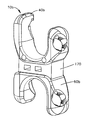
도 1은 추간 공간 내에 설치되는, 예시적인 실시예에 따른 추간 임플란트의 사시도이다.
도 2a는 도 1에 도시된 추간 공간 내에 설치된 추간 임플란트의 부분적으로 투명한 평면도이다.
도 2b는 도 1에 도시된 추간 공간 내에 설치된 추간 임플란트의 부분적으로 투명한 측면도이다.
도 2c는 도 1에 도시된 추간 공간 내에 설치된 추간 임플란트의 후면도이다.
도 3a는 도 1에 도시된 추간 임플란트의 우측 사시도이다.
도 3b는 도 3a에 도시된 추간 임플란트의 좌측 사시도이다.
도 3c는 도 3a에 도시된 추간 임플란트의 분해 사시도이다.
도 4a는 도 3a에 도시된 추간 임플란트의 제1 고정기의 상부 사시도이다.
도 4b는 도 선 4b-4b를 따라 취한, 도 3b에 도시된 추간 임플란트의 부분 측면 사시 단면도이다.
도 5a는 척추 추궁판에 추간 임플란트를 고정시키도록 구성된 뼈 나사의 다축 삽입 방향의 범위를 도시하는, 도 3a에 도시된 추간 임플란트의 일부의 후방 사시도이다.
도 5b는 도 5a에 도시된 뼈 나사의 측면도이다.
도 5c는 도 5a에 도시된 추간 임플란트의 나사 삽입 개구의 확대 사시도이다.
도 6은 도 3a에 도시된 추간 임플란트의 삽입을 위해 구성된 중앙 절개부 및 천자 절개부를 도시하는, 연조직이 없이 도시된 환자 내의 치료 부위의 후면도이다.
도 7a는 예시적인 실시예에 따른 삽입 장치에 의해 유지되는, 도 1에 도시된 추간 공간 내에 설치된 추간 임플란트의 측면 사시도이다.
도 7b는 도 7a에 도시된 삽입 장치의 확장 가능한 본체의 확대된 측면 사시도이다.
도 7c는 도 7a에 도시된 삽입 장치의 확장 팁(tip)에 의해 유지되는, 도 1에 도시된 추간 공간 내에 설치된 추간 임플란트의 확대된 측면 사시도이다.
도 8a는 도 3a에 도시된 추간 임플란트, 및 도 7a에 도시된 삽입 장치의 분해도이다.
도 8b는 도 8a에 도시된 삽입 장치에 의해 유지되는 추간 임플란트의 우측 사시 단면도이다.
도 9a는 드릴 조준 장치 내의 개구를 통해, 척추의 추궁판 내로 구멍을 뚫기 위해 위치된 뼈 드릴의 팁과 함께 도시되어 있는, 도 7a에 도시된 삽입 장치에 의해 유지되는, 도 1에 도시된 추간 공간 내에 설치된 추간 임플란트의 사시도이다.
도 9b는 도 9a에 도시된 드릴 조준 장치의 사시도이다.
도 9c는 다축 드릴링 방향의 범위를 도시하는, 도 9b에 도시된 드릴 조준 장치의 팁의 사시도이다.
도 9d는 추간 임플란트 내의 개구를 통해, 척추의 추궁판 내의 구멍 내로 뼈 나사를 드릴링하는 스크루 드라이버의 팁과 함께 도시되어 있는, 도 7a에 도시된 삽입 장치에 의해 유지되는, 도 1에 도시된 추간 공간 내에 설치된 추간 임플란트의 사시도이다.
도 10a는 다른 실시예에 따른, 스프링을 포함하는 추간 임플란트의 사시도이다.
도 10b는 다른 실시예에 따른, 탄성 감쇠 장치를 포함하는 추간 임플란트의 사시도이다.
도 11a는 추간 임플란트 실시예들 중 하나를 설치하는데 사용하기에 적합한, 다축 고정 메커니즘을 포함하는 뼈 나사의 부분 측단면도이다.
도 11b는 도 11a에 도시된 4개의 뼈 나사를 포함하는, 도 3b에 도시된 추간 임플란트의 전방 단면도이다.1 is a perspective view of an intervertebral implant according to an exemplary embodiment, installed in an intervertebral space.
FIG. 2A is a partially transparent plan view of the intervertebral implant installed in the intervertebral space shown in FIG. 1. FIG.
FIG. 2B is a partially transparent side view of the intervertebral implant installed in the intervertebral space shown in FIG. 1. FIG.
FIG. 2C is a rear view of the intervertebral implant installed in the intervertebral space shown in FIG. 1. FIG.
3A is a right perspective view of the intervertebral implant shown in FIG. 1.
3B is a left perspective view of the intervertebral implant shown in FIG. 3A.
3C is an exploded perspective view of the intervertebral implant shown in FIG. 3A.
4A is a top perspective view of the first anchor of the intervertebral implant shown in FIG. 3A.
4B is a partial side perspective cross-sectional view of the intervertebral implant shown in FIG. 3B, taken along lines 4B-4B.
FIG. 5A is a rear perspective view of a portion of the intervertebral implant shown in FIG. 3A, showing the range of the multiaxial insertion direction of the bone screw configured to secure the intervertebral implant to the spinal plaque.
5B is a side view of the bone screw shown in FIG. 5A.
5C is an enlarged perspective view of the screw insertion opening of the intervertebral implant shown in FIG. 5A.
FIG. 6 is a rear view of the treatment site in a patient shown without soft tissue, showing a central incision and a puncture incision configured for insertion of the intervertebral implant shown in FIG. 3A.
FIG. 7A is a side perspective view of an intervertebral implant installed in the intervertebral space shown in FIG. 1, maintained by an insertion device according to an exemplary embodiment. FIG.
FIG. 7B is an enlarged side perspective view of the expandable body of the insertion device shown in FIG. 7A.
FIG. 7C is an enlarged side perspective view of an intervertebral implant installed in the intervertebral space shown in FIG. 1, held by an expansion tip of the insertion device shown in FIG. 7A.
FIG. 8A is an exploded view of the intervertebral implant shown in FIG. 3A and the insertion device shown in FIG. 7A.
FIG. 8B is a right perspective cross-sectional view of the intervertebral implant held by the insertion device shown in FIG. 8A.
FIG. 9A is the intervertebral body shown in FIG. 1, maintained by the insertion device shown in FIG. 7A, shown with the tip of a bone drill positioned to drill a hole into the vertebral disc of the spine through an opening in the drill aiming device. A perspective view of an intervertebral implant installed in a space.
9B is a perspective view of the drill aiming device shown in FIG. 9A.
9C is a perspective view of the tip of the drill aiming device shown in FIG. 9B showing the range of the multi-axis drilling direction.
FIG. 9D is the intervertebral body shown in FIG. 1, maintained by the insertion device shown in FIG. 7A, shown with the tip of a screwdriver drilling a bone screw through an opening in the intervertebral implant into a hole in the plaque of the spine. A perspective view of an intervertebral implant installed in a space.
10A is a perspective view of an intervertebral implant including a spring, according to another embodiment.
10B is a perspective view of an intervertebral implant that includes an elastic damping device, according to another embodiment.
11A is a partial side cross-sectional view of a bone screw including a multi-axial fixation mechanism suitable for use in installing one of the intervertebral implant embodiments.
FIG. 11B is a front cross-sectional view of the intervertebral implant shown in FIG. 3B, including the four bone screws shown in FIG. 11A.
소정의 용어가 다음의 설명에서 단지 편의상 사용되며, 제한적이지 않다. "우측", "좌측", "하부", 및 "상부"라는 단어는 참조되는 도면 내에서의 방향을 지시한다. "내측으로" 또는 "원위로(distally)" 그리고 "외측으로" 또는 "근위로(proximally)"라는 단어는 확장 가능한 임플란트, 기구 및 그의 관련 부품의 기하학적 중심을 향한 그리고 그로부터 멀어지는 방향을 각각 지칭한다. "전방", "후방", "상위", "하위"라는 단어 및 관련 단어 및/또는 문구는 참조되는 신체 내에서의 우선적인 위치 및 배향을 지시하며, 제한적인 의미는 아니다. 용어들은 상기 열거된 단어, 그의 파생어, 및 유사한 의미의 단어를 포함한다.Certain terms are used merely for convenience in the following description and are not limiting. The words "right", "left", "bottom", and "top" indicate directions in the drawings to which reference is made. The words "inwardly" or "distally" and "outwardly" or "proximally" refer to directions towards and away from the geometric center of the expandable implant, instrument and its associated components, respectively. . The words "forward", "rear", "upper", "lower" and related words and / or phrases indicate, but are not limited to, preferred positions and orientations in the body to which they are referenced. The terms include the words listed above, derivatives thereof, and words of similar meaning.
도 1을 참조하면, 후방 요추 추간 융합술을 위한 확장 가능한 추간 임플란트(10)가 척추 운동 분절(14)을 강화 또는 안정화를 위해 척주(12) 내로 설치되어 도시되어 있다. 척주(12)는 복수의 척추(20)를 포함하고, 각각의 인접한 쌍의 척추(20)들은 추간 디스크(22)에 의해 분리되고, 그들 사이에 추간 공간(24)을 형성한다. 임플란트(10)는 제1 또는 두부 고정기(40) 및 두부 고정기(40)에 대해 이동 가능한 제2 또는 미부 고정기(60)와, 두부 고정기(40)에 대한 미부 고정기(60)의 종방향 위치를 고정시키도록 구성된 서클립(80)을 포함한다. 임플란트(10)는 추간 공간(24) 내로 설치되고, 임플란트(10)는 뼈 나사(16)에 의해 척추(20)에 부착된다. 임플란트(10)는 척추(20)와 융합하도록 구성될 수 있다.Referring to FIG. 1, an expandable
척추(20)는 원하는 대로 임의의 척추 영역 내에 배치될 수 있고, 전후 방향을 따라 연장하는 중심 전후 축(AP-AP)의 대향 측면들 상에 배치된 전방 측면(AS) 및 대향 후방 측면(PS)을 형성하는 요추 영역 내에 도시되어 있다. 척추(20)는 아울러 중측방 방향을 따라 연장하는 중심 중앙 축(M-M)의 대향 측면들 상에 배치되는 대향 측방 측면(LS)들을 형성한다. 척추(20)는 두미 축(C-C)을 따라 이격되어 도시되어 있다. 임플란트(10)는 종방향(L), 측방향(A), 및 횡방향(T)을 따라 대체로 연장한다.The
그러므로, 다양한 구조물이 종방향("L")을 따라 수직으로 그리고 측방향("A") 및 횡방향("T")을 따라 수평으로 연장하는 것으로 설명된다. 추간 임플란트(10)는 종방향(L)으로 확장 가능하다. 본원에서 달리 규정되지 않으면, "종방향", "측방향", 및 "횡방향"이라는 용어는 다양한 성분들 중 직각 방향 성분을 설명하도록 사용된다. "내향" 및 "내측" 또는 "외향" 및 "외측"이라는 방향 용어, 및 이들의 파생어는 본원에서 주어진 장치에 대해, 장치의 기하학적 중심을 향한 그리고 그로부터 멀어지는 방향 성분을 따른 방향을 지칭하도록 사용된다.Therefore, various structures are described as extending vertically along the longitudinal direction ("L") and horizontally along the lateral ("A") and transverse ("T").
측방향 및 횡방향이 수평 평면을 따라 연장하는 것으로 도시되어 있고, 종방향이 수직 평면을 따라 연장하는 것으로 도시되어 있지만, 다양한 방향을 포함하는 평면들이 사용 중에 상이할 수 있음을 이해하여야 한다. 따라서, "수직" 및 "수평"이라는 방향 용어는 명확함 및 예시의 목적으로만 도시된 바와 같이 추간 임플란트(10) 및 그의 구성요소를 설명하도록 사용된다.While the lateral and transverse directions are shown extending along the horizontal plane and the longitudinal direction is shown extending along the vertical plane, it should be understood that the planes including the various directions may be different in use. Thus, the directional terms "vertical" and "horizontal" are used to describe the
도시된 실시예에서, 종방향(L)은 두미 방향으로 연장하고, 측방향(A)은 중측방 방향으로 연장하고, 횡방향(T)은 전후 방향으로 연장한다. 그러나, 확장 가능한 추간 임플란트(10)에 의해 한정되는 방향들은 대안적으로 척추(20)들에 의해 한정되는 다양한 방향에 대해 0°와 180° 사이의 다양한 각도로 배향될 수 있음을 이해하여야 한다. 예를 들어, 임플란트의 측방향 및 횡방향은 중측방 및 전후 방향에 대해 0°와 180° 사이의 다양한 각도로 배향될 수 있다. 아래의 설명으로부터 이해될 바와 같이, 추간 임플란트(10)는 전방 방향, 후방 방향, 또는 전방 및 후방 측면에 대한 0°와 180° 사이의 다양한 대안적인 방향으로 추간 공간(24) 내로 삽입될 수 있다.In the illustrated embodiment, the longitudinal direction L extends in the iron direction, the lateral direction A extends in the middle direction, and the transverse direction T extends in the front-rear direction. However, it should be understood that the directions defined by the expandable
이제 도 2a-2c를 참조하면, 임플란트(10)는 뼈 나사(16)를 척추(20) 내로, 예를 들어 척추(20)의 추궁판(30) 내로 삽입함으로써, 예를 들어 극돌기(36)와 같은 척추(20)의 후방 단부에서, 척추(20)의 뼈 구조물에 부착될 수 있다. 도시된 바와 같이, 뼈 나사(16)는 임플란트(10)에 인접한 2개의 척추(20)의 추궁판(30)들 사이의 후관절(32)을 관통하기에 충분한 길이를 가질 수 있거나, 대안적으로 뼈 나사(16)는 후관절(32)을 관통하지 않도록 더 짧을 수 있다.Referring now to FIGS. 2A-2C, the
뼈 나사(16)의 길이는 임플란트(10)가 척추 운동 분절(14)에 대해 제공하는 안정성의 정도를 결정하기 위해 원하는 대로 선택될 수 있다. 후관절(32)을 관통하지 않는 더 짧은 뼈 나사(16)가 사용되면, 척추 운동 분절(14)은 후측방 융합을 일으키는 제한된 안정성을 가질 수 있다 (즉, 일부 잔류 운동이, 특히 온전한 디스크가 존재할 수 있는 추간 공간에 대해, 임플란트(10)가 설치된 후에 남는다). 후관절(32)을 관통하는 더 긴 뼈 나사(16)가 사용되면, 척추 운동 분절(14)은 강화될 수 있어서, (즉, 추간 디스크(22)를 포함하여) 원주방향 융합의 높은 가능성이 있을 것이다. 각 유형의 융합에서, 뼈 나사(16)는 추공(26) 및 신경공(28) 내로의 관통을 회피한다.The length of the
척추(20)에 임플란트(10)를 부착하기 위한 척추(20)의 척추경(34)의 사용이 회피되어, 척추경(34)을 추가의 척추 퇴행의 경우에 미래의 치료를 위해 이용 가능하게 남겨둔다. 위에서 설명된 바와 같이, 척추경(34)이 제1 임플란트를 부착하기 위해 사용되면, 척추경(34)은 이후의 재건 치료를 위해 생체 역학적으로 훼손될 수 있고, 따라서 이후의 재건은, 예를 들어, 시멘트 보강, 골 형성 단백질(BMP)의 도포, 또는 더 큰 나사의 사용을 요구할 수 있다. 척추(20)에 임플란트(10)를 부착하기 위한 척추(20)의 추궁판(30)의 사용은 척추경 나사의 사용과 관련된 단점들 중 일부 또는 전부를 회피할 수 있다.The use of the
임플란트(10)는 인접한 척추(20)들의 극돌기(36)들 사이에 위치된 추간 공간(24) 내로 끼워지도록 형성된다. 임플란트(10)는 수술 중에, 추간 공간(24) 및/또는 추간 디스크(22)에 의해 점유되는 공간의 수축 또는 확대를 허용하도록 확장되도록 구성된다 (추간 디스크(22)는 필요하다면 제거될 수 있다). 추간 공간(24) 및/또는 추간 디스크(22)에 의해 점유되는 공간의 수축은 추간 공간(24) 및 신경공(28)을 확대시켜서, 환자의 척추의 퇴행 중에 크기가 감소될 수 있었을 이들을 건강한 높이로 회복시킬 수 있다. 추간 공간(24) 및/또는 추간 디스크(22)에 의해 점유되는 공간의 수축은 척추(20)의 퇴행으로 인해 압축되었을 척추관 또는 신경근을 복원할 수 있다.The
이제 도 3a-4b를 참조하면, 두부 고정기(40) 및 미부 고정기(60)는 임플란트(10)가 두미 방향으로 종방향으로 확장 가능하게 허용하도록 서로에 대해 종방향으로 이동 가능하다.Referring now to FIGS. 3A-4B, the
두부 고정기(40)는 기부(47)를 갖는 고정기 본체(46), 및 기부(47)의 측방으로 대향하는 단부들로부터 위로 종방향으로 연장하는 제1 및 제2 날개(52, 54)를 포함한다. 날개(52, 54)는 각각의 내측 표면(53) 및 외측 표면(55)을 형성한다. 제1 날개(52)는 제1 날개(52)를 통해 연장하며 뼈 나사(16)를 수납하도록 구성된 제1 뼈 나사 개구(56)를 포함한다. 제2 날개(54)는 제2 날개(54)를 통해 연장하며 뼈 나사(16)를 수납하도록 구성된 제2 뼈 나사 개구(58)를 포함한다. 기부(47)는 라운딩된 상부 표면(49) 및 대향하는 실질적으로 평탄한 바닥 표면(44)을 형성하지만, 표면(44, 49)들은 원하는 대로 임의의 기하학적 구성을 취할 수 있음을 이해하여야 한다. 날개(42, 54)의 내측 표면(53)은 기부(47)의 상부 표면(49)과 함께 조합하여, 상방으로 배향된 대체로 U-형상인 개방부(41)를 형성한다.The
고정기 본체(46)는 기부(47)의 바닥 표면(44)으로부터 종방향 하방으로 연장하는 대체로 원통형인 코어(51)를 더 포함한다. 코어(51)는 임플란트(10)의 측방향-횡방향 평면 내에서 코어(51)의 외측 표면(45)으로부터 외측으로 연장하는 복수의 걸림 리지(48)와 같은 적어도 하나의 걸림 리지(48)로서 구성될 수 있는 맞물림 부재를 포함한다.The
미부 고정기(60)는 기부(67)를 갖는 고정기 본체(66), 및 기부(67)의 측방향으로 대향하는 단부들로부터 아래로 종방향으로 연장하는 제1 및 제2 날개(72, 74)를 포함한다. 날개(72, 74)는 각각의 내측 표면(73) 및 외측 표면(75)을 형성한다. 제1 날개(72)는 제1 날개(72)를 통해 연장하며 뼈 나사(16)를 수납하도록 구성된 제1 뼈 나사 개구(76)를 형성한다. 제2 날개(74)는 제2 날개(74)를 통해 연장하며 뼈 나사(16)를 수납하도록 구성된 제2 뼈 나사 개구(78)를 형성한다. 기부(67)는 라운딩된 바닥 표면(65) 및 대향하는 실질적으로 평탄한 상부 표면(69)을 형성하지만, 표면(65, 69)들은 원하는 대로 임의의 기하학적 구성을 취할 수 있음을 이해하여야 한다. 날개(72, 74)의 내측 표면(73)은 기부(67)의 바닥 표면(65)과 함께 조합하여, 대체로 U-형상인 개방부(61)를 형성한다.The
미부 고정기 본체(66)는 고정기 본체(66)의 기부(67)의 상부 표면(69)으로부터 종방향 상방으로 연장하는 대체로 원통형인 소켓(62)을 더 포함한다. 소켓(62)은 서클립(80)을 수납하도록 구성된 대체로 원통형인 채널(68)을 포함한다. 소켓(62)은 원하는 대로 서클립(80)을 확대시키기 위해 접근을 허용하도록 구성된 그를 통해 연장하는 접근 개구(70)를 형성한다.The
특히 도 3c를 참조하면, 서클립(80)은 대체로 원통형인 내부 공극(82)을 형성하는 대체로 환상인 본체(81)를 포함한다. 접근 갭(84)이 본체(81)를 통해 연장하고, 사용 중에 소켓(62)의 접근 개구(70)와 정렬되도록 위치된다. 서클립(80)은 코어(51)의 맞물림 부재에 대해 상보적이며 미부 고정기(60)에 대한 두부 고정기(40)의 종방향 위치를 고정시키기 위해 코어(51)와 맞물리도록 구성된 맞물림 부재를 포함한다. 예를 들어, 서클립(80)의 맞물림 부재는 임플란트(10)의 측방향-횡방향 평면 내에서 내측으로 연장하는 복수의 걸림 리지(86)와 같은 적어도 하나의 걸림 리지(86)로서 구성될 수 있다. 서클립(80)이 채널(68) 내부에 배치되면, 환상 본체(81)는 코어(51)에 대해 압축되어, 걸림 리지(86)가 두부 고정기(40)의 걸림 리지(48)와 정합하게 한다. 걸림 리지(48, 86)들의 맞물림은 두부 및 미부 고정기(40, 60)들을 고정된 높이에서 접합시킨다. 아래에서 더 상세하게 설명될 바와 같이, 걸림 리지(48, 86)들의 분리는 임플란트의 높이가 조정되도록 허용한다. 따라서, 코어(51), 소켓(62), 및 서클립(80)은 고정기(40, 60)들이 초기의 제1 높이로부터 제2 원하는 높이로 확장하도록 선택적으로 허용하고, 이후에 고정기(40, 60)들을 제2 원하는 높이에 로킹시키는 로킹 메커니즘(83)을 형성한다.With particular reference to FIG. 3C, the
골 융합 증진제가 U-형상 개방부(61)의 내측 표면에 도포될 수 있다. 예를 들어, U-형상 개방부(61)는 거대 다공성 티타늄으로 코팅 또는 처리될 수 있거나, 표면은 양극 플라즈마 화학 처리로 개선될 수 있다.A bone fusion enhancer may be applied to the inner surface of the
다시 도 3a-4b를 참조하면, 두부 고정기(40)의 U-형상 개방부(41) 및 미부 고정기(60)의 U-형상 개방부(61)는 요추 내의 극돌기(36)의 형상에 대체로 대응하도록 구성된다. 따라서, 개방부(41, 61)는 각각의 극돌기(36)를 수납하도록 구성된다. 다른 실시예에서, 두부 고정기(40)의 U-형상 개방부(41) 및 미부 고정기(60)의 U-형상 개방부(61)는, 예를 들어 경추를 포함한, 척주(12)의 다른 영역 내의 극돌기를 수납하도록 구성될 수 있다.Referring again to FIGS. 3A-4B, the
임플란트(10)의 설치된 종방향 높이는 치료될 척추 운동 분절(14) 내의 인접한 척추(20)들의 극돌기(36)들 사이의 원하는 거리에 의존할 것이다. 임플란트(10)가 처음으로 환자 내로 삽입되면, 임플란트(10)는 임플란트(10)가 최소 높이를 갖는 완전 좌굴 위치에 있을 수 있고, 이때 두부 고정기(40)의 코어(51)는 미부 고정기(60)의 소켓(62) 내로 완전히 삽입된다. 완전 좌굴 위치에서 환자 내로 임플란트(10)를 삽입하는 것은 임플란트(10)가 상대적으로 작은 절개부를 통해 환자 내로 삽입되도록 허용할 수 있어서, 확장 위치에서 임플란트(10)를 삽입하는 것에 비교하여, 척추 수술의 침습성의 정도를 최소화하는 것을 돕는다.The installed longitudinal height of the
임플란트(10)가 환자 내로 삽입된 후에, 임플란트(10)는 치료될 척추 운동 분절(14) 내의 척추 공간(24)의 원하는 종방향 높이 또는 원하는 높이로 종방향으로 확장될 수 있다.After the
임플란트(10)의 종방향 높이를 확장시키기 위해, 서클립(80)의 걸림 리지(86)는 두부 고정기(40)의 걸림 리지(48)로부터 분리된다. 따라서, (도 7a-8b에 도시된 삽입 장치(110)의 팁과 같은) 공구가 서클립(80)의 내부 공극(82)을 확대 또는 확장시키기 위해 접근 개구(70)를 통해 접근 갭(84) 내로 삽입된다. 서클립(80)이 확대되어 채널(68)의 내부를 확장시키면, 걸림 리지(86)는 두부 고정기(40)의 걸림 리지(48)와의 맞물림으로부터 해제되어, 두부 고정기(40)가 미부 고정기(60)에 대해 종방향으로 상방 및 하방으로 이동되도록 허용한다. 미부 고정기(60)에 대한 두부 고정기(40)의 상방 이동은 임플란트(10)의 종방향 높이가 증가되도록, 두부 고정기(40)의 코어(51)가 미부 고정기(60)의 소켓(62)으로부터 취출되기 시작하게 한다.In order to extend the longitudinal height of the
두부 고정기(40)가 임플란트(10)가 원하는 높이를 달성하도록 미부 고정기(60)에 대해 상방으로 이동되면, 서클립(80)은 삽입 장치(110)를 제거함으로써 해제될 수 있어서, 서클립(80)의 내부 공극(82)이 그의 초기 크기로 복귀하도록 허용하고, 이는 걸림 리지(86)가 두부 고정기(40)의 걸림 리지(48)와 다시 맞물리게 한다. 서클립(80)의 걸림 리지(86)가 두부 고정기(40)의 걸림 리지(48)와 다시 맞물리면, 임플란트(10)의 높이는 원하는 높이로 고정된다.When the
두부 고정기(40)가 도면에서 두미 축(C-C)을 따라 미부 고정기(60) 위에 위치되는 것으로 도시되어 있지만, 다른 실시예에서, 임플란트(10)는 두부 고정기(40)가 두미 축(C-C)을 따라 미부 고정기(60) 아래에 위치되도록, 도시된 배향에 대해 뒤집혀서 설치될 수 있다.Although the
두부 고정기(40)는 원통형 코어(51)를 포함하는 것으로 도시되어 있고 미부 고정기(60)는 소켓(62)을 포함하는 것으로 도시되어 있지만, 다른 실시예에서, 두부 고정기(40)는 소켓을 포함할 수 있고, 미부 고정기(60)는 두부 고정기(40)의 소켓 내로 종방향으로 활주하도록 구성된 원통형 코어를 포함할 수 있다.The
미부 고정기(60)가 횡방향(T)으로 그를 통해 연장하는 단일 접근 개구(70)를 포함하는 것으로 도시되어 있지만, 다른 실시예에서, 접근 개구(70)는 임플란트(10)의 측방향-횡방향 평면 내의 임의의 방향에서 원주방향으로 배향될 수 있다. 미부 고정기는 필요하다면 복수의 접근 개구를 더 포함할 수 있다. 접근 개구(70)가 대안적인 배향을 갖는 실시예에서, 서클립(80)의 접근 갭(84)은 접근 개구(70)와 정렬되어 그를 통해 접근되도록 원주방향으로 배향될 수 있다.Although the
임플란트(10)의 높이를 감소시키는 것이 이후에 필요하다면, 서클립(80)은 서클립(80)의 내부 공극(82)을 확대시키기 위해, 접근 개구(70)를 통해 접근 갭(84) 내로 삽입 장치(110)를 삽입함으로써 다시 확대될 수 있다. 서클립(80)이 확대되어 채널(68)의 내부를 확장시키면, 걸림 리지(86)는 두부 고정기(40)의 걸림 리지(48)와의 맞물림으로부터 해제되어, 두부 고정기(40)가 미부 고정기(60)에 대해 종방향 하방으로 이동되도록 허용한다. 임플란트(10)가 원하는 높이를 달성하도록 두부 고정기(40)가 하방으로 이동되면, 서클립(80)은 공구를 제거함으로써 해제될 수 있어서, 서클립(80)의 내부 공극(82)이 그의 초기 크기로 복귀하도록 허용하고, 이는 걸림 리지(86)가 두부 고정기(40)의 걸림 리지(48)와 다시 맞물리게 한다.If it is subsequently necessary to reduce the height of the
로킹 메커니즘(83)은 일 실시예에 따라 도시되었고, 로킹 메커니즘은 고정기(40, 60)들이 초기 높이로부터 원하는 높이로 확장하도록 허용하고, 이후에 고정기(40, 60)들을 원하는 높이에 로킹시키도록 구성된 대안적인 구조를 형성할 수 있음을 이해하여야 한다.Locking
두부 고정기(40) 및 미부 고정기(60)는 환자의 내부에서 임플란트로서 사용하기에 적합한 임의의 재료로부터 만들어질 수 있다. 예를 들어, 두부 고정기(40) 및 미부 고정기(60)는 티타늄과 같이, 장기간 하중 지지 임플란트로서 사용하기에 적합한 임의의 금속으로부터 만들어질 수 있다. 두부 고정기 및/또는 미부 고정기(60)는, 예를 들어, PCU 및/또는 유사한 탄성 열가소성 중합체를 포함한, (재흡수성이 아닌) 생체 안정형인 하나 이상의 탄성 중합체로부터 만들어질 수 있다. 두부 고정기 및/또는 미부 고정기(60)는, 예를 들어, PEEK 또는 탄소 섬유 보강 PEEK를 포함한, 하나 이상의 방사선 투과성 중합체로부터 만들어질 수 있다.
이제 도 5a-5c를 참조하면, 두부 고정기(40)의 제1 날개(52) 및 제2 날개(54)와 미부 고정기(60)의 제1 날개(72) 및 제2 날개(74)는 비대칭으로 위치된 각각의 제1 뼈 나사 개구(56, 76) 및 제2 뼈 나사 개구(58, 78)를 포함한다. 제1 뼈 나사 개구(56, 76) 및 제2 뼈 나사 개구(58, 78)는 경추궁판 뼈 나사(16)가 척추(20)의 추궁판(30)을 통과함으로써 척추(20)에 임플란트(10)를 부착하는 것을 허용하도록 구성된다. 제2 뼈 나사 개구(58, 78)와 비교한 제1 뼈 나사 개구(56, 76)의 비대칭 상대 위치는 뼈 나사가 각각의 척추(20)의 추궁판(30) 내로 삽입될 때 뼈 나사(16)들의 간섭을 방지한다.Referring now to FIGS. 5A-5C, the
도시된 바와 같이, 제1 뼈 나사 개구(56, 76)는 제2 뼈 나사 개구(58, 78)보다 각각의 두부 고정기(40)의 바닥(44) 및 미부 고정기(60)의 상부(69)로부터 더 큰 종방향 거리에 위치된다. 다른 실시예에서, 제2 뼈 나사 개구(58, 78)는 제1 뼈 나사 개구(56, 76)보다 각각의 두부 고정기(40)의 바닥(44) 및 미부 고정기(60)의 상부(69)로부터 더 큰 종방향 거리에 위치될 수 있다.As shown, the first
대안적인 실시예에 따르면, 제1 뼈 나사 개구(56, 76) 및 제2 뼈 나사 개구(58, 78)는 각각의 두부 고정기(40)의 바닥(44) 및 미부 고정기(60)의 상부(69)로부터 대체로 동일한 종방향 거리에 위치된다. 이러한 실시예에서, 제1 뼈 나사 개구(56, 76)의 삽입 각도의 범위는 추궁판(30) 내에서의 뼈 나사(16)들의 간섭이 회피되도록, 제2 뼈 나사 개구(58, 78)의 삽입 각도의 범위와 충분히 상이할 수 있다.According to an alternative embodiment, the first
도 5b 및 5c에서 볼 수 있는 바와 같이, 각각의 뼈 나사(16)와 각각의 제1 뼈 나사 개구(56, 76) 및 제2 뼈 나사 개구(58, 78)는 다축 로킹 나사 메커니즘을 포함한다. 각각의 뼈 나사(16)는 나사식 샤프트(90) 및 나사식 헤드(92)를 포함한다. 각각의 나사식 헤드(92)는 실질적으로 구형인 형상을 갖는다. 각각의 제1 뼈 나사 개구(56, 76) 및 제2 뼈 나사 개구(58, 78)는 뼈 나사(16)의 나사식 헤드(92)를 부분적으로만 지탱하도록 구성된 태핑된(tapped) 부분(94)을 포함한다.As can be seen in FIGS. 5B and 5C, each
각각의 뼈 나사(16)의 나사식 구형 헤드(92)와 나사식 헤드(92)를 부분적으로만 지탱하도록 구성된 태핑된 부분(94)의 조합은 각각의 제1 뼈 나사 개구(56, 76) 및 제2 뼈 나사 개구(58, 78)에 대한 가변 삽입 각도(96)가 가능한 뼈 나사(16)를 생성한다. 다축 로킹 나사 메커니즘에 관련된 추가의 내용은 본원에 전체적으로 설명되어 참조로 통합된, 2009년 5월 26일자로 출원된 공동 계류 중인 미국 가특허 출원 제61/181,149호에 도시되고 설명되어 있다.The combination of the threaded
제1 뼈 나사 개구(56, 76) 및 제2 뼈 나사 개구(58, 78)에 의해 제공되는 다축 로킹 나사 메커니즘은 의사가 각각의 뼈 나사(16)를 가변 삽입 각도(96)로 삽입하도록 허용한다. 그러한 가변 삽입 각도(96)는 뼈 나사들이 척추(20)의 추궁판(30) 내로 삽입될 때 뼈 나사(16)들 사이의 접촉을 회피하고, 아울러 뼈 나사(16)의 추공(26) 및 신경공(28) 내로의 관통 및 척추관 또는 신경근과의 접촉을 회피하기 위해, 의사가 나사 샤프트를 원하는 방향으로 유도하도록 허용할 수 있다.The multi-axis locking screw mechanism provided by the first
각각의 뼈 나사(16)와 각각의 제1 뼈 나사 개구(56, 76) 및 제2 뼈 나사 개구(58, 78) 내에 포함된 다축 로킹 나사 메커니즘의 로킹 특징부는 임플란트(10)가 척주(12)의 척추 운동 분절(14)에 인가되는 하중을 견디도록 허용하여, 임플란트(10)가 요추 후방 융합술을 위한 안정된 치료가 되도록 허용한다.The locking feature of the multi-axis locking screw mechanism included in each
이제 도 6을 참조하면, 임플란트(10)는 임플란트(10)의 설치를 위한 원하는 척추 운동 분절(14) 부근에서, 척주(12)의 요추 부분을 따른 상대적으로 작은 중앙 절개부(100)를 통해 환자 내로 삽입될 수 있다. 뼈 나사(16)는 각각의 천자 절개부(102)를 통해 환자 내로 삽입될 수 있고, 이를 통해 드릴(104)이 뼈 나사(16)의 삽입을 위해 척추(20)의 추궁판(30) 내에 유도 구멍을 제공할 수 있다. 임플란트(10)는 본 기술 분야의 당업자에 의해 공지된 바와 같이 경추궁판 나사 고정 기술을 사용하여 환자 내로 설치될 수 있다. 몇몇 실시예에서, 캐뉼라형 뼈 나사가 환자 내로의 임플란트(10)의 삽입을 보조하기 위해 안내 와이어와 함께 사용될 수 있다.Referring now to FIG. 6, the
추간 디스크(22)에 의해 점유되는 공간 내로 임플란트를 설치하기보다, 추간 공간(24) 내로 임플란트(10)를 설치하는 것이 의사가 (환자에게 더 침습적인) 전방 절개부 내로보다, (환자에게 덜 침습적인) 후방 절개부 내로 임플란트(10)를 설치하도록 허용할 수 있다. 또한, 척추(20)의 척추경(34) 내로가 아닌 척추(20)의 추궁판(30) 내로 임플란트(10)를 설치하는 것은 척추경 나사를 설치할 때 일반적인 척추(20)로부터의 주 근육 탈리를 회피한다.Rather than installing the implant into the space occupied by the
이제, 도 7a-8b를 참조하면, 임플란트(10)는 삽입 장치(110)를 사용하여 환자 내로 삽입될 수 있다. 임플란트(10) 및 삽입 장치(110)는 함께 추간 임플란트 시스템(111)을 형성한다. 삽입 장치(110)는 삽입 장치(110)를 파지하도록 구성된 손잡이(112), 서클립(80)과 맞물리고 이를 해제하도록 구성되고 아울러 임플란트(10)의 높이를 설정하도록 구성된 제어 접속부(114), 및 임플란트(10)를 유지하며 위치 설정하도록 구성된 확장 가능한 본체(116)를 포함한다. 캐뉼라형 중심 튜브(118)가 제어 접속부(114)에 연결되는 근위 단부(119), 및 확장 가능한 본체(116)에 연결되는 대향 원위 단부(121)를 형성한다.Referring now to FIGS. 7A-8B, the
중심 튜브(118)는 외측 슬리브(123)에 의해 둘러싸인 병진 이동 막대(122)를 보유한다. 외측 슬리브(123)는 그의 원위 단부에서, 치형부(135)를 제시하는 캐뉼라형 피니언(126)에 연결된다. 대안적으로, 외측 슬리브(123)는 피니언(126)에 일체로 결합될 수 있다. 병진 이동 막대(122)는 피니언(126)을 통해 연장하고, 중심 튜브의 원위 단부(121)로부터 중심 튜브(118)의 근위 단부(119)를 향한 방향을 따라 외측으로 벌어지는 한 쌍의 대향하는 경사 표면(127)을 형성할 수 있는, 맞물림 팁(128)과 같은 작동기를 형성한다.
제어 접속부(114)는 막대(122)에 결합된 병진 이동 플런저(120)를 포함한다. 횡방향(T)을 따른 플런저(120)의 병진 이동은 막대(122)가 횡방향(T)을 따라 유사하게 병진 이동하게 한다. 막대(122)의 전방 병진 운동은 팁(128)을 소켓(62) 내의 접근 개구(70)를 통해 서클립(80)의 접근 갭(84) 내로 삽입한다. 경사진 외측 표면(127)은 서클립(80)이 확장하게 하여, 두부 고정기(40)의 걸림 리지(48)로부터 서클립(80)의 걸림 리지(86)를 분리한다. 플런저(120)의 후방 이동은 팁(128)을 접근 갭(84)으로부터 제거하고, 이는 서클립(80)이 걸림 리지(86, 48)들이 맞물리는 그의 초기 구성으로 좌굴하도록 허용한다. 이와 관련하여, 팁(128)은 서클립(80)이 걸림 리지(48)로부터 걸림 리지(86)를 분리시키게 하여, 두부 및 미부 고정기(40, 60)들 중 적어도 하나가 종축을 따라 다른 것에 대해 이동하도록 허용하는 제1 위치로부터, 두부 및 미부 고정기(40, 60)들이 서로에 대해 종방향으로 이동하는 것을 방지하는 제2 위치로 이동할 수 있는 작동기로서 지칭될 수 있다.The
계속해서 도 7a-8b를 참조하면, 확장 가능한 본체(116)는 두부 슬라이더 하우징(140) 및 두부 슬라이더 하우징(140)을 수납하는 미부 지지 하우징(130)을 포함한다. 지지 하우징(130)은 중심 튜브(118)의 원위 단부(121)에 결합되는 하우징 본체(137)를 형성한다. 지지 하우징(130)은 한 쌍의 측방향으로 이격된 수직 아암(139), 및 하우징 본체 수직 아암(139)으로부터 전방으로 연장하는 한 쌍의 이격된 미부 핑거(132)를 포함한다. 미부 핑거(132)는 원통형 소켓(62)의 외부 둘레에 미부 고정기(60)를 고정시키도록 구성된다.With continued reference to FIGS. 7A-8B,
슬라이더 하우징(140)은 본체(141), 및 본체(141)로부터 전방으로 연장하며 사이에 두부 고정기(40)를 보유하도록 구성된 한 쌍의 두부 핑거(142)를 포함한다. 특히, 두부 핑거(142)는 두부 고정기(40) 내로 연장하는 횡방향 개구(43) 내로 연장함으로써 두부 고정기(40)를 고정시킨다. 본체(141)는 피니언(126)을 수납하는 내부 개방부(143)를 형성한다. 본체(141)는 피니언(126)의 치형부(135)와 정합하는 개방부 내로 돌출하는 치형부(146)를 제시하는 랙(144)을 포함한다. 제어 접속부(114)는 캐뉼라형 피니언(126) 상으로 회전 운동을 부여하도록 구성된 회전 작동기(124)를 포함하고, 이는 피니언(126)의 치형부(135)가 랙(144)과 슬라이더 하우징(140)을 지지 하우징(130) 내에서 두미 방향으로 병진 이동하도록 구동하여 팁(116)을 확장시키게 한다.The
작동 중에, 의사는 임플란트(10)가 최소 높이를 갖는 완전 좌굴 위치에서 환자 내로 임플란트(10)를 설치할 수 있고, 이때 두부 고정기(40)의 코어(51)는 미부 고정기(60)의 소켓(62) 내로 완전히 삽입되어, 중앙 절개부의 크기가 최소화될 수 있다. 환자 내로 임플란트(10)를 설치하기 위해, 의사는 핑거(132, 142)들이 위에서 설명된 방식으로 임플란트(10) 보유하도록, 두부 고정기(40)를 두부 핑거(142)들 사이에 그리고 미부 고정기(60)를 미부 핑거(132)들 사이에 삽입한다. 의사는 그 다음 손잡이(112)를 파지하고, 임플란트(10)를 삽입 장치(110)에 의해 중앙 절개부(100) 내로 이동시킨다. 임플란트(10)가 원하는 척추 운동 분절(14) 내의 추간 공간(24) 내로 위치되면, 의사는 미부 고정기(60)를 추궁판(30)에 로킹시키기 위해 뼈 나사(16)를 사용하여, 하부 척추(20)의 추궁판(30)에 미부 고정기(60)를 부착한다.During operation, the surgeon may install the
미부 고정기(60)가 추궁판(30)에 부착되면, 의사는 미부 고정기(60)에 대해 두부 고정기(40)를 종방향으로 이동시킴으로써 임플란트(10)의 수직 높이를 증가시키기 시작할 수 있다. 의사는 우선 임플란트(10)를 향해 횡방향(T)을 따라 병진 이동 플런저(120)를 이동시킴으로써 두부 고정기(40)로부터 서클립(80)을 해제한다. 병진 이동 플런저(120)가 횡방향(T)을 따라 이동할 때, 막대(122)의 팁(128)은 소켓(62) 내의 접근 개구(70)를 통해 서클립(80)의 접근 갭(84) 내로 삽입되어, 경사 표면(127)이 두부 고정기(40)의 걸림 리지(48)로부터 서클립(80)의 걸림 리지(86)를 분리하게 한다.Once the
서클립(80)이 두부 고정기(40)로부터 분리되면, 의사는 회전 작동기(124)를 시계방향으로 회전시킴으로써 미부 고정기(60)에 대해 두부 고정기(40)를 상승시킬 수 있다. 회전 작동기(124)가 시계방향으로 회전될 때, 캐뉼라형 피니언(126)은 랙(144)에 대해 시계방향으로 회전되어, 슬라이더 하우징(140)을 지지 하우징(130)에 대해 종방향(L)을 따라 상방으로 이동시키고 팁(116)을 확장시킨다. 확장 가능한 본체(116)의 두부 슬라이더 하우징(140)이 미부 지지 하우징(130)에 대해 종방향(L)을 따라 상방으로 이동함에 따라, 두부 고정기(40)는 미부 고정기(60)에 대해 종방향(L)을 따라 상방으로 이동한다.Once the
임플란트(10)가 원하는 높이에 도달하여, 두부 고정기(40)가 미부 고정기(60)에 대한 원하는 종방향 위치로 이동되면, 의사는 추궁판(30)에 두부 고정기(40)를 로킹시키기 위해 뼈 나사(16)를 사용하여, 상부 척추(20)의 추궁판(30)에 두부 고정기(40)를 부착한다. 임플란트(10)가 척추(20)들의 추궁판(30)에 완전히 고정되면, 의사는 삽입 장치(110)를 임플란트(10)와의 맞물림으로부터 당겨내고, 중앙 절개부(100)로부터 삽입 장치(110)를 제거하여, 환자 내에서의 임플란트(10)의 설치를 완료한다. 원하는 척추 운동 분절(14) 내의 추간 공간(24) 내에서의 임플란트(10)의 위치는 x-선과 같은 진단 시험에 의해 평가될 수 있다.When the
이제 도 9a-9d를 참조하면, 척추(20)들의 추궁판(30)에 임플란트(10)를 부착하기 전에, 의사는 뼈 나사(16)의 삽입을 위해 추궁판(30) 내에 유도 구멍을 제공하기 위해 드릴(104)을 사용할 수 있다. 추궁판(30) 내에 유도 구멍을 뚫기 위해, 조준 장치(150)가 중앙 절개부(100)를 통해 환자 내로 삽입될 수 있고, 이때 의사는 임플란트(10)가 설치될 원하는 척추 운동 분절(14) 내의 추간 공간(24)을 관찰할 수 있다. 드릴(104)의 드릴 비트(106)가 천자 절개부(102)를 통해 조준 장치(150)의 개구(152) 내로 삽입된다.Referring now to FIGS. 9A-9D, prior to attaching the
조준 장치(150)의 개구(152)는 다축 조준 장치(150)의 가변 삽입 각도(154)를 제공하면서, 드릴 비트(106)의 삽입 각도를 제한한다. 조준 장치(150)의 개구(152)의 가변 삽입 각도(154)는 각각의 뼈 나사(16)와 각각의 제1 뼈 나사 개구(56, 76) 및 제2 뼈 나사 개구(58, 78) 내에 포함된 다축 로킹 나사 메커니즘의 가변 삽입 각도(96)와 대체로 정합하도록 구성될 수 있다. 다축 조준 장치(150)의 가변 삽입 각도(154)가 다축 로킹 나사 메커니즘의 가변 삽입 각도(96)에 대체로 정합되면, 추궁판(30) 내의 뚫린 유도 구멍이 뼈 나사(16)의 원하는 삽입 각도를 수용할 수 있는 것이 가능할 것이다. 유도 구멍이 추궁판(30) 내에 뚫리면, 스크루 드라이버(156)가 추궁판(30) 내로 뼈 나사(16)를 삽입하기 위해 천자 절개부(102)를 통해 삽입될 수 있다.The
이제 도 10a를 참조하면, 후방 요추 추간 안정화를 위한 제2 실시예의 확장 가능한 추간 임플란트(10a)가 두부 고정기(40a), 두부 고정기(40a)에 대해 이동 가능한 미부 고정기(60a), 및 두부 고정기(40a) 및 미부 고정기(60a)를 서로를 향해 이동시키는 압축력에 저항하도록 개방 위치로 편의되는, 두부 고정기(40a)와 미부 고정기(60a) 사이에 위치된 블레이드 스프링(160)을 포함한다. 블레이드 스프링(160)이 도 10a에 도시되어 있지만, 임의의 유형의 스프링 또는 압축 가능한 장치가 두부 고정기(40a)와 미부 고정기(60b) 사이의 압축력에 저항하도록 사용될 수 있다.Referring now to FIG. 10A, the expandable
임플란트(10a)는 뼈 나사(16)에 의해 인접한 척추(20)들의 추궁판(30)에 임플란트(10a)를 부착함으로써 도 1-2c에 도시된 척주(12)의 척추 운동 분절(14)의 추간 공간(24) 내로 설치하기에 적합하다. 그러한 실시예는, 예를 들어, 의사가 원하는 척추 운동 분절(14)의 운동을 감쇠시키고 원하는 척추 운동 분절(14)의 높이를 회복하기를 의도할 때, 사용될 수 있다.The
임플란트(10a)는 제1 높이를 갖는 제1 위치에서, 도 6에 도시된 중앙 절개부(100)를 통해 환자 내로 삽입될 수 있고, 임플란트(10a)는 두부 고정기(40a) 및 미부 고정기(60a)가 도 9a-9d에 도시된 바와 같이 뼈 나사(16)에 의해 인접한 극돌기(36)들에 부착될 수 있도록, 의사가 두부 고정기(40a) 및 미부 고정기(60a)로부터 압축 압력을 해제하면 제1 높이보다 더 큰 제2 높이를 갖는 제2 또는 확장 위치로 확장할 수 있다.The
이제 도 10b를 참조하면, 후방 요추 추간 안정화를 위한 제3 실시예의 확장 가능한 추간 임플란트(10b)가 두부 고정기(40b), 두부 고정기(40b)에 대해 이동 가능한 미부 고정기(60b), 및 두부 고정기(40b) 및 미부 고정기(60b)를 서로를 향해 이동시키는 압축력에 저항하도록 개방 위치로 편의되는, 두부 고정기(40b)와 미부 고정기(60b) 사이에 위치된 탄성 감쇠기(170)를 포함한다.Referring now to FIG. 10B, the expandable
도 10b에 도시된 바와 같이, 탄성 감쇠기(170)는 점탄성 진행으로 척추 운동 분절(14)의 운동을 감쇠시킬 수 있는 탄성체 또는 중합체이다. 다른 실시예에서, 임의의 유형의 탄성 감쇠기 또는 압축 가능한 장치가 두부 고정기(40b)와 미부 고정기(60b) 사이의 압축력에 저항하도록 사용될 수 있다.As shown in FIG. 10B, the
임플란트(10b)는 뼈 나사(16)에 의해 인접한 척추(20)들의 추궁판(30)에 임플란트(10b)를 부착함으로써 도 1-2c에 도시된 척주(12)의 척추 운동 분절(14)의 추간 공간(24) 내로 설치하기에 적합하다. 그러한 실시예는, 예를 들어, 의사가 원하는 척추 운동 분절(14)의 운동을 감쇠시키고 원하는 척추 운동 분절(14)의 높이를 회복하기를 의도할 때, 사용될 수 있다.The
임플란트(10b)는 압축 위치에서, 도 6에 도시된 중앙 절개부(100)를 통해 환자 내로 삽입될 수 있고, 임플란트(10b)의 높이는 두부 고정기(40b) 및 미부 고정기(60b)가 도 9a-9d에 도시된 바와 같이 뼈 나사(16)에 의해 인접한 극돌기(36)들에 부착될 수 있도록, 의사가 두부 고정기(40b) 및 미부 고정기(60b)로부터 압축 압력을 해제하면 확장할 수 있다.The
압축 압력이 임플란트(10b)로부터 해제되면, 척추 운동 분절(14)의 높이의 회복은 압축 압력이 해제된 후에 느리게 달성된다. 예를 들어, 척추 운동 분절(14)의 높이의 이러한 느린 회복은 취성의 또는 경화된 골질을 갖는 고령 환자에 대해 유리할 수 있다.When the compression pressure is released from the
이제 도 11a 및 11b를 참조하면, 뼈 나사(16a)가 편향 가능한 헤드 부분(184)을 형성하는 구형 헤드(182) 둘레에 위치된 확장 링(180), 및 헤드(182) 내에 위치된 확장 나사(186)를 포함하는 다축 고정 메커니즘을 포함한다. 각각의 뼈 나사(16a)는 확장 링(180)과 정합하도록 구성된 태핑되지 않은 내부 표면(94a)을 포함하는 각각의 제1 뼈 나사 개구(56a, 76a) 및 제2 뼈 나사 개구(58a, 78a) 내로 로킹되도록 구성된다.Referring now to FIGS. 11A and 11B, an
(도 11a 및 11b에 도시된) 뼈 나사(16a)와, 태핑되지 않은 내부 표면(94a)을 포함하는 뼈 나사 개구(56a, 58a, 76a, 78a)는 뼈 나사(16a)에 의해 인접한 척추(20)들의 추궁판(30)에 임플란트를 부착함으로써 도 1-2c에 도시된 척주(12)의 척추 운동 분절(14)의 추간 공간(24) 내로 추간 임플란트(10, 10a, 또는 10b)들 중 하나를 설치할 때 (도 5a-5c에 도시된) 뼈 나사(16)와 태핑된 부분(94)을 포함하는 뼈 나사 개구(56, 58, 76, 78)에 대한 대안으로서 사용하기에 적합하다.
인접한 척추(20)들의 추궁판(30)에 임플란트(10, 10a, 또는 10b)를 설치하기 위해 뼈 나사(16a)를 사용하기 위해, 의사는 우선 도 9a에 도시된 바와 같이, 드릴 비트로 추궁판(30) 내로 하나 이상의 유도 구멍을 뚫는다. 유도 구멍이 뚫리면, 의사는 임플란트(10, 10a, 또는 10b)에 대한 원하는 각도로 각각의 뼈 나사(16a)를 배향한다. 뼈 나사(16)와 유사하게, 뼈 나사(16a)는 도 5a에 도시된 바와 같이 각각의 뼈 나사 개구에 대한 가변 삽입 각도(96)를 의사에게 제공하도록 구성된다.In order to use the
각각의 뼈 나사(16a)에 대한 원하는 각도가 선택되면, 의사는 각각의 뼈 나사(16a)를 각각의 뼈 나사 개구를 통해 추궁판(30) 내로 전진시킨다. 두부 고정기(40c) 또는 미부 고정기(60c) 내로 각각의 뼈 나사(16a)를 로킹시키기 위해, 의사는 각각의 확장 나사(186)를 전진시키고, 이는 편향 가능한 헤드 부분(184)을 편향하여서, 각각의 헤드(182)를 확대시켜서 헤드(182)를 확장 링(180)에 대해 로킹시키고, 헤드는 태핑되지 않은 내부 표면(94a)에 대해 로킹된다.Once the desired angle for each
상기 설명은 설명의 목적으로 제공되며, 본 발명을 제한하는 것으로 해석되어서는 안 된다. 본 발명이 바람직한 실시예 또는 바람직한 방법을 참조하여 설명되었지만, 본원에서 사용된 단어는 제한적인 단어가 아닌, 설명 및 예시의 단어임이 이해된다. 또한, 본 발명이 특정 구조, 방법, 및 실시예를 참조하여 본원에서 설명되었지만, 본 발명은 첨부된 특허청구범위의 범주 내에 있는 모든 구조, 방법, 및 용도로 확장되므로, 본원에서 개시된 세부로 제한되도록 의도되지 않는다. 아울러, 구조 및 방법으로부터 유래하는 여러 장점이 설명되었고; 본 발명은 이러한 장점들 중 임의의 하나 또는 전부를 포함하는 구조 및 방법으로 제한되지 않는다. 척추 임플란트 기술의 당업자는 본 명세서의 개시 내용을 이용하여, 본원에서 설명되는 본 발명에 대한 많은 변형을 이룰 수 있고, 변화가 첨부된 특허청구범위에 의해 한정되는 본 발명의 범주 및 사상으로부터 벗어남이 없이 이루어질 수 있다. 또한, 하나의 설명된 실시예의 임의의 특징은 본원에서 설명되는 다른 실시예에 적용될 수 있다. 예를 들어, 특정한 확장 가능한 추간 임플란트의 설명에 대한 두부 고정기 또는 미부 고정기의 설계에 관련된 임의의 특징 또는 장점이 본원에서 설명되는 다른 확장 가능한 추간 임플란트 실시예들 중 하나에 적용될 수 있다.The description is provided for purposes of explanation and should not be construed as limiting the invention. Although the present invention has been described with reference to preferred embodiments or preferred methods, it is understood that the words used herein are words of description and illustration, rather than words of limitation. In addition, while the invention has been described herein with reference to specific structures, methods, and examples, the invention extends to all structures, methods, and uses that fall within the scope of the appended claims, and therefore are limited to the details disclosed herein. It is not intended to be. In addition, several advantages from structures and methods have been described; The present invention is not limited to structures and methods that include any one or all of these advantages. Those skilled in the art of spinal implant technology can use the disclosure herein to make many modifications to the invention described herein, and variations are hereby departed from the scope and spirit of the invention as defined by the appended claims. It can be done without. In addition, any feature of one described embodiment can be applied to other embodiments described herein. For example, any feature or advantage related to the design of the head anchorage or tail anchorage for the description of a particular expandable intervertebral implant can be applied to one of the other expandable intervertebral implant embodiments described herein.
Claims (31)
제1 척추의 추궁판에 부착되도록 구성된, 제1 고정기 기부를 포함하는 제1 고정기;
제2 척추의 추궁판에 부착되도록 구성된, 제2 고정기 기부를 포함하는 제2 고정기;
제2 고정기 기부로부터 외부로 연장하는 소켓; 및
제1 고정기 기부로부터 외부로 연장하고 소켓 내에 수납되는 크기이며, 제2 고정기에 대한 제1 고정기의 위치를 해제 가능하게 고정시키도록 구성된 맞물림 부재를 포함하는 코어
를 포함하는 확장 가능한 추간 임플란트.An expandable intervertebral implant configured to be inserted into an intervertebral space formed between the first and second vertebrae,
A first anchor comprising a first anchor base configured to attach to the plaque plate of the first spine;
A second anchor including a second anchor base configured to attach to the plaque plate of the second spine;
A socket extending outwardly from the second anchor base; And
A core extending outwardly from the first anchor base and received in the socket, the core including an engagement member configured to releasably lock the position of the first anchor relative to the second anchor;
Extendable intervertebral implant comprising a.
인접한 척추들 사이에 형성된 추간 공간 내로 삽입되어 인접한 척추들의 극돌기에 부착되도록 구성된 추간 임플란트 - 임플란트는 제1 고정기, 제2 고정기, 및 제1 및 제2 고정기가 제1 높이로부터 제2 높이로 확장하도록 선택적으로 허용하는 로킹 메커니즘을 포함함 -; 및
임플란트에 결합되도록 구성된 삽입 장치 - 삽입 장치는 선택적으로 로킹 메커니즘을 해제하여 제1 및 제2 고정기가 제1 높이로부터 제2 높이로 확장하도록 허용하기 위해 로킹 메커니즘과 선택적으로 맞물리도록 구성되는 작동기를 포함함 -
를 포함하는 시스템.Scalable intervertebral implant system,
An intervertebral implant configured to be inserted into an intervertebral space formed between adjacent vertebrae and attached to the spinous process of adjacent vertebrae, the implant having a first anchor, a second anchor, and a first and second anchor from the first height to the second height. Includes a locking mechanism to selectively allow expansion; And
Insertion device configured to be coupled to an implant, the insertion device including an actuator configured to selectively engage the locking mechanism to selectively release the locking mechanism to allow the first and second fasteners to extend from the first height to the second height Has-
/ RTI >
종방향 높이를 형성하며, 코어를 갖는 제1 고정기 및 코어를 수납하도록 구성되는 소켓을 갖는 제2 고정기를 포함하는 임플란트를 삽입 장치 내로 삽입하는 단계;
제1 척추 및 제2 척추를 포함하는, 척추 운동 분절의 척추들 사이의 추간 공간 내로 임플란트를 삽입하는 단계;
제2 척추의 추궁판에 제2 고정기를 부착하는 단계;
제1 고정기 및 제2 고정기 중 적어도 하나를 다른 하나에 대해 병진 이동시켜서, 추간 임플란트의 종방향 높이를 증가시키는 단계;
제1 고정기에 대한 제2 고정기의 위치를 고정시키는 단계; 및
제1 척추의 추궁판에 제1 고정기를 부착하는 단계
를 포함하는 방법.A method of expanding intervertebral implants for posterior lumbar intervertebral fusion of spinal motion segments,
Inserting an implant into the insertion device, the implant defining a longitudinal height, the implant including a first anchor having a core and a second anchor having a socket configured to receive the core;
Inserting an implant into the intervertebral space between the vertebrae of the spinal motor segment, the first spine and the second spine;
Attaching a second anchor to the vertebral plaque of the second spine;
Translating at least one of the first anchor and the second anchor relative to the other to increase the longitudinal height of the intervertebral implant;
Fixing the position of the second fixture relative to the first fixture; And
Attaching the first anchor to the vertebral plaque of the first spine
≪ / RTI >
서클립의 내측 연장 걸림 리지가 제1 고정기 코어의 외측 연장 걸림 리지로부터 분리되도록 서클립을 확대시키는 단계; 및
제1 고정기 코어의 걸림 리지 내로 서클립의 걸림 리지를 맞물려서, 제1 고정기에 대한 제2 고정기의 위치를 고정시키기 위해 서클립을 해제하는 단계
를 더 포함하는 방법.The method of claim 30, wherein the implant further defines a circlip configured to fix the longitudinal position of the second anchor with respect to the first anchor.
Expanding the circlip such that the inner extension locking ridge of the circlip is separated from the outer extension locking ridge of the first fixture core; And
Releasing the circlip to engage the catch ridge of the circlip into the catch ridge of the first fixture core to fix the position of the second holder relative to the first fixture.
≪ / RTI >
Applications Claiming Priority (3)
| Application Number | Priority Date | Filing Date | Title |
|---|---|---|---|
| US31049210P | 2010-03-04 | 2010-03-04 | |
| US61/310,492 | 2010-03-04 | ||
| PCT/US2011/025832 WO2011109197A2 (en) | 2010-03-04 | 2011-02-23 | Expandable lamina spinal fusion implant |
Publications (1)
| Publication Number | Publication Date |
|---|---|
| KR20130018666A true KR20130018666A (en) | 2013-02-25 |
Family
ID=43971692
Family Applications (1)
| Application Number | Title | Priority Date | Filing Date |
|---|---|---|---|
| KR1020127022692A KR20130018666A (en) | 2010-03-04 | 2011-02-23 | Expandable lamina spinal fusion implant |
Country Status (8)
| Country | Link |
|---|---|
| US (1) | US20110218572A1 (en) |
| EP (1) | EP2542167A2 (en) |
| JP (1) | JP2013521050A (en) |
| KR (1) | KR20130018666A (en) |
| CN (1) | CN102791210B (en) |
| BR (1) | BR112012020550A2 (en) |
| CA (1) | CA2787847A1 (en) |
| WO (1) | WO2011109197A2 (en) |
Families Citing this family (32)
| Publication number | Priority date | Publication date | Assignee | Title |
|---|---|---|---|---|
| EP3097878A1 (en) | 2011-02-06 | 2016-11-30 | Paradigm Spine, LLC | Translaminar interspinous stabilization system |
| US20120215262A1 (en) * | 2011-02-16 | 2012-08-23 | Interventional Spine, Inc. | Spinous process spacer and implantation procedure |
| US10080591B2 (en) * | 2011-02-17 | 2018-09-25 | Globus Medical Inc | Lateral spine stabilization devices and methods |
| US20120259363A1 (en) * | 2011-04-08 | 2012-10-11 | Kyphon Sarl | Viscoelastic lumbar-sacral implant |
| CN104220017B (en) | 2012-01-05 | 2017-04-12 | 兰克斯公司 | Telescoping interspinous fixation device and methods of use |
| US9566165B2 (en) | 2012-03-19 | 2017-02-14 | Amicus Design Group, Llc | Interbody vertebral prosthetic and orthopedic fusion device with self-deploying anchors |
| US9622876B1 (en) | 2012-04-25 | 2017-04-18 | Theken Spine, Llc | Expandable support device and method of use |
| AU2013308332B2 (en) * | 2012-08-31 | 2017-01-19 | Newsouth Innovations Pty Limited | Bone stabilization device and methods of use |
| US9592083B2 (en) | 2013-08-30 | 2017-03-14 | New South Innovations Pty Limited | Spine stabilization device |
| US9259249B2 (en) | 2013-11-26 | 2016-02-16 | Globus Medical, Inc. | Spinous process fixation system and methods thereof |
| US9554831B2 (en) | 2014-04-21 | 2017-01-31 | Warsaw Orthopedic, Inc. | Intervertebral spinal implant and method |
| US9622872B2 (en) | 2014-09-23 | 2017-04-18 | Warsaw Orthopedic, Inc. | Intervertebral spinal implant and method |
| CN108366816A (en) | 2015-07-31 | 2018-08-03 | 帕拉迪格脊骨有限责任公司 | Interspinous stabilization and fusing device |
| WO2017087020A1 (en) * | 2015-11-20 | 2017-05-26 | Amicus Design Group, Llc. | Interbody vertebral prosthetic and orthopedic fusion device with self-deploying anchors |
| TWI616182B (en) * | 2016-10-21 | 2018-03-01 | Wang hong zhen | Retractable spinal laminar stabilizer |
| WO2018119672A1 (en) * | 2016-12-27 | 2018-07-05 | 马向阳 | Vertebral plate interbody fusion cage |
| US11806250B2 (en) | 2018-02-22 | 2023-11-07 | Warsaw Orthopedic, Inc. | Expandable spinal implant system and method of using same |
| RU2701131C1 (en) * | 2018-11-12 | 2019-09-24 | Федеральное государственное бюджетное военное образовательное учреждение высшего образования "Военно-медицинская академия имени С.М. Кирова" Министерства обороны Российской Федерации (ВМедА) | Method of posterior spondylosyndesis with bone defect plasty after laminectomy |
| US10918421B2 (en) * | 2019-05-07 | 2021-02-16 | Warsaw Orthopedic, Inc. | Spinal implant system and methods of use |
| CN110538014B (en) * | 2019-10-08 | 2024-05-14 | 宋兴华 | Fusion device and fusion device assembly for minimally invasive surgery |
| US11833059B2 (en) | 2020-11-05 | 2023-12-05 | Warsaw Orthopedic, Inc. | Expandable inter-body device, expandable plate system, and associated methods |
| US11285014B1 (en) | 2020-11-05 | 2022-03-29 | Warsaw Orthopedic, Inc. | Expandable inter-body device, system, and method |
| US11517363B2 (en) | 2020-11-05 | 2022-12-06 | Warsaw Orthopedic, Inc. | Screw driver and complimentary screws |
| US11517443B2 (en) | 2020-11-05 | 2022-12-06 | Warsaw Orthopedic, Inc. | Dual wedge expandable implant, system and method of use |
| US11963881B2 (en) | 2020-11-05 | 2024-04-23 | Warsaw Orthopedic, Inc. | Expandable inter-body device, system, and method |
| US11291554B1 (en) | 2021-05-03 | 2022-04-05 | Medtronic, Inc. | Unibody dual expanding interbody implant |
| US11376134B1 (en) | 2020-11-05 | 2022-07-05 | Warsaw Orthopedic, Inc. | Dual expanding spinal implant, system, and method of use |
| US11395743B1 (en) | 2021-05-04 | 2022-07-26 | Warsaw Orthopedic, Inc. | Externally driven expandable interbody and related methods |
| US11638653B2 (en) | 2020-11-05 | 2023-05-02 | Warsaw Orthopedic, Inc. | Surgery instruments with a movable handle |
| US11612499B2 (en) | 2021-06-24 | 2023-03-28 | Warsaw Orthopedic, Inc. | Expandable interbody implant |
| US11730608B2 (en) | 2021-07-13 | 2023-08-22 | Warsaw Orthopedic, Inc. | Monoblock expandable interbody implant |
| US11850163B2 (en) | 2022-02-01 | 2023-12-26 | Warsaw Orthopedic, Inc. | Interbody implant with adjusting shims |
Family Cites Families (25)
| Publication number | Priority date | Publication date | Assignee | Title |
|---|---|---|---|---|
| US5314491A (en) * | 1990-02-02 | 1994-05-24 | Zimmer, Inc. | Prosthetic socket implant |
| ES2182055T3 (en) * | 1997-04-15 | 2003-03-01 | Synthes Ag | TELESCOPIC VERTEBRA PROTESIS. |
| FR2811540B1 (en) * | 2000-07-12 | 2003-04-25 | Spine Next Sa | IMPORTING INTERVERTEBRAL IMPLANT |
| FR2845587B1 (en) * | 2002-10-14 | 2005-01-21 | Scient X | DYNAMIC DEVICE FOR INTERVERTEBRAL CONNECTION WITH MULTIDIRECTIONALLY CONTROLLED DEBATMENT |
| US7819922B2 (en) * | 2003-10-16 | 2010-10-26 | Spinal Generations, Llc | Vertebral prosthesis |
| US7297146B2 (en) * | 2004-01-30 | 2007-11-20 | Warsaw Orthopedic, Inc. | Orthopedic distraction implants and techniques |
| US8070816B2 (en) * | 2004-03-29 | 2011-12-06 | 3Hbfm, Llc | Arthroplasty spinal prosthesis and insertion device |
| US7776091B2 (en) * | 2004-06-30 | 2010-08-17 | Depuy Spine, Inc. | Adjustable posterior spinal column positioner |
| US7837688B2 (en) * | 2005-06-13 | 2010-11-23 | Globus Medical | Spinous process spacer |
| FR2889937B1 (en) * | 2005-08-26 | 2007-11-09 | Abbott Spine Sa | INTERVERTEBRAL IMPLANT FOR LOMBO-SACRED JOINT |
| WO2007034516A1 (en) * | 2005-09-21 | 2007-03-29 | Sintea Biotech S.P.A. | Device, kit and method for intervertebral stabilization |
| CN101578072A (en) * | 2005-09-28 | 2009-11-11 | 新特斯有限责任公司 | Apparatus and methods for vertebral augmentation using linked expandable bodies |
| US8357181B2 (en) * | 2005-10-27 | 2013-01-22 | Warsaw Orthopedic, Inc. | Intervertebral prosthetic device for spinal stabilization and method of implanting same |
| US7879096B2 (en) * | 2006-04-27 | 2011-02-01 | Warsaw Orthopedic, Inc. | Centrally driven expandable implant |
| DE202006006898U1 (en) * | 2006-04-29 | 2006-07-27 | Metz-Stavenhagen, Peter, Dr. Med. | spinal implant |
| US8034081B2 (en) * | 2007-02-06 | 2011-10-11 | CollabComl, LLC | Interspinous dynamic stabilization implant and method of implanting |
| ZA200905203B (en) * | 2007-03-13 | 2010-07-28 | Synthesis Gmbh | Adjustable intervertebral implant |
| EP1994900A1 (en) * | 2007-05-22 | 2008-11-26 | Flexismed SA | Interspinous vertebral implant |
| US8709054B2 (en) * | 2007-08-07 | 2014-04-29 | Transcorp, Inc. | Implantable vertebral frame systems and related methods for spinal repair |
| US8202300B2 (en) * | 2007-12-10 | 2012-06-19 | Custom Spine, Inc. | Spinal flexion and extension motion damper |
| EP2087857A1 (en) * | 2008-02-07 | 2009-08-12 | K2M, Inc. | Expandable vertebral device with cam lock |
| AU2009228030B2 (en) * | 2008-03-28 | 2014-01-16 | K2M, Inc. | Expandable cage with locking device |
| JP2012500057A (en) * | 2008-08-13 | 2012-01-05 | ジンテス ゲゼルシャフト ミット ベシュレンクテル ハフツング | Interspinous spacer assembly |
| US8623056B2 (en) * | 2008-10-23 | 2014-01-07 | Linares Medical Devices, Llc | Support insert associated with spinal vertebrae |
| WO2011047157A1 (en) * | 2009-10-14 | 2011-04-21 | Latitude Holdings, Llc | Spinous process fixation plate and minimally invasive method for placement |
-
2011
- 2011-02-23 KR KR1020127022692A patent/KR20130018666A/en not_active Application Discontinuation
- 2011-02-23 WO PCT/US2011/025832 patent/WO2011109197A2/en active Application Filing
- 2011-02-23 CN CN201180011668.0A patent/CN102791210B/en not_active Expired - Fee Related
- 2011-02-23 CA CA2787847A patent/CA2787847A1/en not_active Abandoned
- 2011-02-23 BR BR112012020550A patent/BR112012020550A2/en not_active IP Right Cessation
- 2011-02-23 EP EP11706717A patent/EP2542167A2/en not_active Withdrawn
- 2011-02-23 JP JP2012556104A patent/JP2013521050A/en active Pending
- 2011-02-23 US US13/033,145 patent/US20110218572A1/en not_active Abandoned
Also Published As
| Publication number | Publication date |
|---|---|
| US20110218572A1 (en) | 2011-09-08 |
| CA2787847A1 (en) | 2011-09-09 |
| JP2013521050A (en) | 2013-06-10 |
| WO2011109197A2 (en) | 2011-09-09 |
| CN102791210B (en) | 2014-11-26 |
| CN102791210A (en) | 2012-11-21 |
| WO2011109197A3 (en) | 2011-11-10 |
| BR112012020550A2 (en) | 2017-06-27 |
| EP2542167A2 (en) | 2013-01-09 |
Similar Documents
| Publication | Publication Date | Title |
|---|---|---|
| KR20130018666A (en) | Expandable lamina spinal fusion implant | |
| RU2618898C2 (en) | Surgical implants for endermal vertebral leg extension during spinal stenosis elimination | |
| JP4481301B2 (en) | Guide wire insertion device | |
| US9579131B1 (en) | Systems and methods for performing spine surgery | |
| US10980528B2 (en) | Devices and systems for surgical retraction | |
| JP5356509B2 (en) | Intervertebral implants and placement instruments | |
| US11241258B2 (en) | Bone screw | |
| US9649133B2 (en) | Supplemental fixation screw | |
| JP2008529748A (en) | Implant and method for positioning an implant in a spine with a surgical approach | |
| US20050197660A1 (en) | Occipital and cervical stabilization systems and methods | |
| CN112312851A (en) | Modular screw system with adjustable length | |
| US20080234678A1 (en) | Rod reducer | |
| US20090012568A1 (en) | System and method for providing surgical access to a spine | |
| US20090082775A1 (en) | Spondylolisthesis reduction system and method | |
| CN110891501A (en) | Spinal fixation access and delivery system | |
| KR20120001759A (en) | Interspinous process implant and fusion cage spacer | |
| US20100036434A1 (en) | Rescue reduction bone anchor | |
| JP7029959B2 (en) | Spine stabilizer | |
| JP2017523860A (en) | Connecting rod insert | |
| US9622793B1 (en) | Expandable spinal fixation system | |
| US20220160402A1 (en) | Bone screw | |
| US11918262B2 (en) | Fixation device and method of using the same | |
| EP3503817B1 (en) | Minimally invasive surgical system | |
| US10806494B2 (en) | Fixation devices, fixation systems, and methods of using the same | |
| WO2024081282A2 (en) | Spinal fixation |
Legal Events
| Date | Code | Title | Description |
|---|---|---|---|
| WITN | Application deemed withdrawn, e.g. because no request for examination was filed or no examination fee was paid |