KR20130005233A - Encoding and decoding methods for video information - Google Patents
Encoding and decoding methods for video information Download PDFInfo
- Publication number
- KR20130005233A KR20130005233A KR1020120071616A KR20120071616A KR20130005233A KR 20130005233 A KR20130005233 A KR 20130005233A KR 1020120071616 A KR1020120071616 A KR 1020120071616A KR 20120071616 A KR20120071616 A KR 20120071616A KR 20130005233 A KR20130005233 A KR 20130005233A
- Authority
- KR
- South Korea
- Prior art keywords
- prediction
- region
- prediction region
- mode
- intra
- Prior art date
Links
- 238000000034 method Methods 0.000 title claims abstract description 69
- 239000013074 reference sample Substances 0.000 claims description 86
- 239000000523 sample Substances 0.000 claims description 51
- 238000006243 chemical reaction Methods 0.000 abstract description 19
- 238000005192 partition Methods 0.000 description 28
- 230000006835 compression Effects 0.000 description 17
- 238000007906 compression Methods 0.000 description 17
- 208000037170 Delayed Emergence from Anesthesia Diseases 0.000 description 9
- 238000000638 solvent extraction Methods 0.000 description 9
- 108091026890 Coding region Proteins 0.000 description 8
- 238000010586 diagram Methods 0.000 description 8
- 238000001125 extrusion Methods 0.000 description 8
- 230000009466 transformation Effects 0.000 description 8
- 239000000470 constituent Substances 0.000 description 7
- 230000008569 process Effects 0.000 description 6
- 238000013139 quantization Methods 0.000 description 4
- 230000011664 signaling Effects 0.000 description 4
- 230000000694 effects Effects 0.000 description 3
- 230000006872 improvement Effects 0.000 description 3
- 230000001131 transforming effect Effects 0.000 description 3
- 230000003044 adaptive effect Effects 0.000 description 2
- 230000001419 dependent effect Effects 0.000 description 2
- 230000010365 information processing Effects 0.000 description 2
- 238000005457 optimization Methods 0.000 description 2
- 241000023320 Luma <angiosperm> Species 0.000 description 1
- 108700026244 Open Reading Frames Proteins 0.000 description 1
- 230000007423 decrease Effects 0.000 description 1
- 230000006866 deterioration Effects 0.000 description 1
- 230000018109 developmental process Effects 0.000 description 1
- OSWPMRLSEDHDFF-UHFFFAOYSA-N methyl salicylate Chemical compound COC(=O)C1=CC=CC=C1O OSWPMRLSEDHDFF-UHFFFAOYSA-N 0.000 description 1
- 238000012986 modification Methods 0.000 description 1
- 230000004048 modification Effects 0.000 description 1
- 230000011218 segmentation Effects 0.000 description 1
Images


Classifications
-
- H—ELECTRICITY
- H04—ELECTRIC COMMUNICATION TECHNIQUE
- H04N—PICTORIAL COMMUNICATION, e.g. TELEVISION
- H04N19/00—Methods or arrangements for coding, decoding, compressing or decompressing digital video signals
- H04N19/10—Methods or arrangements for coding, decoding, compressing or decompressing digital video signals using adaptive coding
- H04N19/169—Methods or arrangements for coding, decoding, compressing or decompressing digital video signals using adaptive coding characterised by the coding unit, i.e. the structural portion or semantic portion of the video signal being the object or the subject of the adaptive coding
- H04N19/17—Methods or arrangements for coding, decoding, compressing or decompressing digital video signals using adaptive coding characterised by the coding unit, i.e. the structural portion or semantic portion of the video signal being the object or the subject of the adaptive coding the unit being an image region, e.g. an object
- H04N19/176—Methods or arrangements for coding, decoding, compressing or decompressing digital video signals using adaptive coding characterised by the coding unit, i.e. the structural portion or semantic portion of the video signal being the object or the subject of the adaptive coding the unit being an image region, e.g. an object the region being a block, e.g. a macroblock
-
- H—ELECTRICITY
- H04—ELECTRIC COMMUNICATION TECHNIQUE
- H04N—PICTORIAL COMMUNICATION, e.g. TELEVISION
- H04N19/00—Methods or arrangements for coding, decoding, compressing or decompressing digital video signals
- H04N19/50—Methods or arrangements for coding, decoding, compressing or decompressing digital video signals using predictive coding
- H04N19/593—Methods or arrangements for coding, decoding, compressing or decompressing digital video signals using predictive coding involving spatial prediction techniques
-
- H—ELECTRICITY
- H04—ELECTRIC COMMUNICATION TECHNIQUE
- H04N—PICTORIAL COMMUNICATION, e.g. TELEVISION
- H04N19/00—Methods or arrangements for coding, decoding, compressing or decompressing digital video signals
- H04N19/10—Methods or arrangements for coding, decoding, compressing or decompressing digital video signals using adaptive coding
- H04N19/102—Methods or arrangements for coding, decoding, compressing or decompressing digital video signals using adaptive coding characterised by the element, parameter or selection affected or controlled by the adaptive coding
- H04N19/103—Selection of coding mode or of prediction mode
- H04N19/11—Selection of coding mode or of prediction mode among a plurality of spatial predictive coding modes
-
- H—ELECTRICITY
- H04—ELECTRIC COMMUNICATION TECHNIQUE
- H04N—PICTORIAL COMMUNICATION, e.g. TELEVISION
- H04N19/00—Methods or arrangements for coding, decoding, compressing or decompressing digital video signals
- H04N19/10—Methods or arrangements for coding, decoding, compressing or decompressing digital video signals using adaptive coding
- H04N19/102—Methods or arrangements for coding, decoding, compressing or decompressing digital video signals using adaptive coding characterised by the element, parameter or selection affected or controlled by the adaptive coding
- H04N19/119—Adaptive subdivision aspects, e.g. subdivision of a picture into rectangular or non-rectangular coding blocks
-
- H—ELECTRICITY
- H04—ELECTRIC COMMUNICATION TECHNIQUE
- H04N—PICTORIAL COMMUNICATION, e.g. TELEVISION
- H04N19/00—Methods or arrangements for coding, decoding, compressing or decompressing digital video signals
- H04N19/10—Methods or arrangements for coding, decoding, compressing or decompressing digital video signals using adaptive coding
- H04N19/102—Methods or arrangements for coding, decoding, compressing or decompressing digital video signals using adaptive coding characterised by the element, parameter or selection affected or controlled by the adaptive coding
- H04N19/132—Sampling, masking or truncation of coding units, e.g. adaptive resampling, frame skipping, frame interpolation or high-frequency transform coefficient masking
-
- H—ELECTRICITY
- H04—ELECTRIC COMMUNICATION TECHNIQUE
- H04N—PICTORIAL COMMUNICATION, e.g. TELEVISION
- H04N19/00—Methods or arrangements for coding, decoding, compressing or decompressing digital video signals
- H04N19/10—Methods or arrangements for coding, decoding, compressing or decompressing digital video signals using adaptive coding
- H04N19/134—Methods or arrangements for coding, decoding, compressing or decompressing digital video signals using adaptive coding characterised by the element, parameter or criterion affecting or controlling the adaptive coding
- H04N19/146—Data rate or code amount at the encoder output
- H04N19/15—Data rate or code amount at the encoder output by monitoring actual compressed data size at the memory before deciding storage at the transmission buffer
Abstract
Description
본 발명은 영상 정보 압축 기술에 관한 것으로서, 더 구체적으로는 인트라 예측 모드에 종속적인 영상 영역 분할 방법 및 장치에 관한 것이다.The present invention relates to image information compression technology, and more particularly, to an image region segmentation method and apparatus that are dependent on an intra prediction mode.
최근 HD(High Definition) 해상도를 가지는 방송 서비스가 국내뿐만 아니라 세계적으로 확대되면서, 많은 사용자들이 고해상도, 고화질의 영상에 익숙해지고 있으며 이에 따라 많은 기관들이 차세대 영상기기에 대한 개발에 박차를 가하고 있다. 또한 HDTV와 더불어 HDTV의 4배 이상의 해상도를 갖는 UHD(Ultra High Definition)에 대한 관심이 증대되면서 보다 높은 해상도, 고화질의 영상에 대한 압축기술이 요구되고 있다.Recently, as broadcasting services having high definition (HD) resolution have been expanded not only in Korea but also in the world, many users are accustomed to high resolution and high quality images, and many organizations are accelerating the development of next generation video equipment. In addition, as interest in Ultra High Definition (UHD), which has four times the resolution of HDTV, is increasing along with HDTV, a compression technology for higher resolution and higher quality images is required.
영상 압축 기술에는 시간적으로 이전 및/또는 이후의 픽쳐로부터 현재 픽쳐에 포함된 화소값을 예측하는 인터(inter) 예측 기술, 현재 픽쳐 내의 화소 정보를 이용하여 현재 픽쳐에 포함된 화소값을 예측하는 인트라(intra) 예측 기술, 조명 변화 등에 의한 화질의 열화를 방지하기 위한 가중치 예측 기술, 출현 빈도가 높은 심볼(symbol)에 짧은 부호를 할당하고 출현 빈도가 낮은 심볼에 긴 부호를 할당하는 엔트로피 부호화 기술 등이 있다. 특히, 생략 모드(skip mode)에서 현재 블록에 대한 예측이 수행되는 경우, 이전 부호화된 영역으로부터 예측된 값만을 이용하여 예측 블록이 생성되고 별도의 움직임 정보(motion information)나 레지듀얼(residual) 신호가 부호화기로부터 복호화기로 전송되지 않는다. 이러한 영상 압축 기술들에 의해 영상 데이터가 효율적으로 압축될 수 있다.Image compression techniques include an inter prediction technique that predicts pixel values included in a current picture from a previous and / or subsequent picture in time, and an intra predictor of pixel values included in a current picture using pixel information in the current picture. (intra) prediction technique, weight prediction technique to prevent deterioration of image quality due to lighting changes, entropy encoding technique for assigning short codes to symbols with high appearance frequency and long codes to symbols with low appearance frequency, etc. There is this. In particular, when prediction is performed on a current block in a skip mode, a prediction block is generated using only a value predicted from a previously coded region, and a separate motion information or residual signal is generated. Is not sent from the encoder to the decoder. Image data can be efficiently compressed by these image compression techniques.
한편, 영상 정보의 압축 기술 중 인트라 예측에는 다양한 인트라 예측 모드가 사용된다. 예측 모드에 따라서, 서로 다른 참조 샘플을 이용하여 현재 블록의 화소값이 예측될 수 있다. 따라서, 서로 다른 예측 모드, 즉 서로 다른 참조 샘플에 따라서 예측 방법을 적응적으로 변경하여 최적의 압축 효율을 얻는 방법을 고려할 수 있다.Meanwhile, various intra prediction modes are used for intra prediction among compression techniques of image information. According to the prediction mode, pixel values of the current block may be predicted using different reference samples. Therefore, a method of obtaining an optimal compression efficiency by adaptively changing the prediction method according to different prediction modes, that is, different reference samples, may be considered.
본 발명에 따른 기술적 과제는 인트라 부호화의 효율을 높이고 영상 정보 처리 과정의 복잡도를 낮추는 방법을 제공하는 것이다. The technical problem according to the present invention is to provide a method of increasing the efficiency of intra coding and reducing the complexity of the image information processing process.
본 발명에 따른 다른 기술적 과제는 인트라 예측 모드에 따라서 예측 영역(Prediction Unit: PU) 및 변환 영역(Transform Unit: TU)를 달리 분할하는 방법을 제공하는 것이다. Another technical problem according to the present invention is to provide a method for dividing a prediction unit (PU) and a transform unit (TU) differently according to an intra prediction mode.
본 발명에 따른 또 다른 기술적 과제는 예측 모드와 상관없이 예측 영역과 변환 영역이 분할됨으로써 발생하던 복잡도의 문제를 해결하는 방법을 제공하는 것이다. Another technical problem according to the present invention is to provide a method for solving the problem of complexity caused by splitting the prediction domain and the transform domain regardless of the prediction mode.
본 발명에 따른 또 다른 기술적 과제는 예측 모드에 따라서 분할된 각 예측 영역에 대한 예측 모드의 결정 방법을 제공하는 것이다. Another technical problem according to the present invention is to provide a method of determining a prediction mode for each prediction region divided according to a prediction mode.
본 발명에 따른 또 다른 기술적 과제는 인트라 예측의 성능 향상을 도모함과 동시에 최적의 예측 영역 분할 구조 및 최적의 변환 영역 분할 구조를 판단하는데 필요한 복잡도를 줄이기 위한 예측 영역 및 변환 영역 분할 방법을 제공하는 것이다.Another technical problem according to the present invention is to provide a prediction domain and a transform domain partitioning method for improving the performance of intra prediction and at the same time reducing the complexity required for determining an optimal prediction domain partition structure and an optimal transform domain partition structure. .
(1) 본 발명이 일 실시형태는 영상 정보의 복호화 방법으로서, 인트라 예측 모드에 따라서, 예측 영역을 제1 예측 영역과 제2 예측 영역으로 분할하는 단계, 상기 제1 예측 영역에 대한 인트라 예측 및 복원을 수행하는 단계 및 상기 제2 예측 영역에 대한 예측 및 복원을 수행하는 단계를 포함하며, 상기 제2 예측 영역에 대한 예측 및 복원 단계에서는, 상기 제1 예측 영역에 대한 참조 샘플 또는 상기 복원된 제1 예측 영역 내 소정의 샘플을 참조하여 상기 제2 예측 영역에 대한 인트라 예측을 수행할 수 있다. (1) An embodiment of the present invention provides a decoding method of image information, comprising: dividing a prediction region into a first prediction region and a second prediction region according to an intra prediction mode, intra prediction of the first prediction region, and Performing a reconstruction and predicting and reconstructing the second prediction region, wherein in the predicting and reconstructing the second prediction region, a reference sample or the reconstructed reference to the first prediction region is performed. Intra prediction of the second prediction region may be performed with reference to a predetermined sample in the first prediction region.
(2) (1)에서, 상기 인트라 예측 모드에 관한 정보는 부호화기로부터 수신될 수 있으며, 상기 예측 영역 분할 단계에서는, 상기 인트라 예측 모드를 사용하는 경우에 기준치 이상의 레지듀얼 신호가 존재하는 영역을 상기 제2 예측 영역으로 설정할 수 있다.(2) In (1), the information about the intra prediction mode may be received from an encoder, and in the prediction region dividing step, when the intra prediction mode is used, an area where a residual signal of a reference value or more exists is used. It may be set as the second prediction region.
(3) (1)에서, 상기 인트라 예측 모드에 관한 정보는 부호화기로부터 수신될 수 있으며, 상기 제2 예측 영역은 상기 인트라 예측 모드의 참조 샘플로부터 현재 블록 내에서 가장 먼 위치의 영역일 수 있다.(3) In (1), the information about the intra prediction mode may be received from an encoder, and the second prediction area may be an area of the position farthest in the current block from a reference sample of the intra prediction mode.
(4) (1)에서, 상기 인트라 예측 모드에 관한 정보는 부호화기로부터 수신될 수 있으며, 상기 제1 예측 영역 및 제2 예측 영역은 인트라 예측 모드별로 미리 설정될 수 있다.(4) In (1), the information about the intra prediction mode may be received from an encoder, and the first prediction region and the second prediction region may be preset for each intra prediction mode.
(5) (1)에서, 상기 제2 예측 영역에 대한 인트라 예측 및 복원 단계에서는, 상기 제2 예측 영역에 대응하는 변환 영역의 변환 계수를 기반으로 레지듀얼 신호를 생성하고, 상기 제2 예측 영역에 대한 예측 결과를 상기 생성된 레지듀얼 신호와 결합하여 복원 신호를 생성할 수 있다.(5) In (1), in the intra prediction and reconstruction of the second prediction region, a residual signal is generated based on a transform coefficient of a transform region corresponding to the second prediction region, and the second prediction region is generated. The reconstruction signal may be generated by combining the prediction result with respect to the generated residual signal.
(6) (1)에서, 상기 제2 예측 영역은 복수의 예측 영역으로 더 분할될 수 있으며, 상기 제2 예측 영역으로부터 분할된 예측 영역에 대해서는 상기 제1 예측 영역에 대한 참조 샘플 또는 복원된 다른 예측 영역 내 소정의 샘플을 참조하여 인트라 예측을 수행할 수 있다. (6) In (1), the second prediction region may be further divided into a plurality of prediction regions, and for a prediction region divided from the second prediction region, a reference sample or another reconstructed reference to the first prediction region is performed. Intra prediction may be performed by referring to a predetermined sample in the prediction region.
(7) (1)에서, 상기 제2 예측 영역에 적용되는 예측 모드는 상기 제1 예측 영역에 적용되는 예측 모드 및 상기 제1 예측 영역에 적용되는 예측 모드와 유사한 각도의 예측 모드 중에서 선택될 수 있다.(7) In (1), the prediction mode applied to the second prediction region may be selected from a prediction mode applied to the first prediction region and a prediction mode having an angle similar to that of the prediction mode applied to the first prediction region. have.
(8) (7)에서, 상기 제2 예측 영역에 대한 인트라 예측은 상기 복원된 제1 영역 내 샘플을 참조하여 수행될 수 있다.(8) In (7), intra prediction for the second prediction region may be performed with reference to a sample in the reconstructed first region.
(9) (1)에서, 상기 제2 예측 영역에 적용되는 예측 모드는 상기 제1 예측 영역에 대한 후보 예측 모드 중에서 선택될 수 있다.(9) In (1), a prediction mode applied to the second prediction region may be selected from candidate prediction modes for the first prediction region.
(10) (1)에서, 상기 제2 예측 영역에 적용되는 예측 모드는 상기 제2 예측 영역에 인접한 블록에 적용된 예측 모드 및 상기 제2 예측 영역에 인접한 블록에 적용된 예측 모드와 유사한 각도의 예측 모드 중에서 선택될 수 있다.(10) In (1), the prediction mode applied to the second prediction region is a prediction mode applied to a block adjacent to the second prediction region and a prediction mode having an angle similar to the prediction mode applied to the block adjacent to the second prediction region. Can be selected from.
(11) 본 발명의 다른 실시형태는 영상 정보의 부호화 방법으로서, 인트라 예측 모드에 따라서, 예측 영역을 제1 예측 영역과 제2 예측 영역으로 분할하는 단계, 상기 제1 예측 영역에 대한 인트라 예측 및 복원을 수행하는 단계, 상기 제2 예측 영역에 대한 예측 및 복원을 수행하는 단계 및 현재 블록의 예측 모드에 관한 정보를 전송하는 단계를 포함하며, 상기 제2 예측 영역에 대한 예측 및 복원 단계에서는, 상기 제1 예측 영역에 대한 참조 샘플 또는 상기 복원된 제1 예측 영역 내 소정의 샘플을 참조하여 상기 제2 예측 영역에 대한 인트라 예측을 수행할 수 있다. (11) Another embodiment of the present invention provides a method of encoding image information, the method comprising: dividing a prediction region into a first prediction region and a second prediction region according to an intra prediction mode, intra prediction of the first prediction region, and Performing a reconstruction, performing a prediction and reconstruction of the second prediction region, and transmitting information about a prediction mode of the current block, wherein the predicting and reconstruction of the second prediction region includes: Intra prediction of the second prediction region may be performed by referring to a reference sample of the first prediction region or a predetermined sample in the reconstructed first prediction region.
(12) (11)에서, 상기 예측 영역 분할 단계에서는, 상기 인트라 예측 모드를 사용하는 경우에 기준치 이상의 레지듀얼 신호가 존재하는 영역을 상기 제2 예측 영역으로 설정할 수 있다.(12) In (11), in the prediction region dividing step, when the intra prediction mode is used, an area in which a residual signal having a reference value or more exists may be set as the second prediction region.
(13) (11)에서, 상기 제2 예측 영역은 상기 인트라 예측 모드의 참조 샘플로부터 현재 블록 내에서 가장 먼 위치의 영역일 수 있다.(13) In (11), the second prediction region may be the region of the position furthest from the current sample from the reference sample of the intra prediction mode.
(14) (11)에서, 상기 제2 예측 영역에 대한 인트라 예측 및 복원 단계에서는, 상기 제2 예측 영역에 대응하는 변환 영역의 변환 계수를 기반으로 레지듀얼 신호를 생성하고, 상기 제2 예측 영역에 대한 예측 결과를 상기 생성된 레지듀얼 신호와 결합하여 복원 신호를 생성할 수 있다. (14) In (11), in the intra prediction and reconstruction of the second prediction region, a residual signal is generated based on transform coefficients of the transform region corresponding to the second prediction region, and the second prediction region is generated. The reconstruction signal may be generated by combining the prediction result with respect to the generated residual signal.
(15) (14)에서, 상기 변환 영역은 상기 제1 예측 영역 및 제2 예측 영역과 동일한 크기의 영역이거나 상기 제1 예측 영역 또는 제2 예측 영역이 정방형 또는 비정방형으로 분할된 영역일 수 있다.(15) In (14), the transform region may be a region having the same size as the first prediction region and the second prediction region or a region in which the first prediction region or the second prediction region is divided into square or non-square. .
(16) (11)에서, 상기 제1 예측 영역 및 제2 예측 영역의 분할 단계에서는, 상기 제2 예측 영역을 복수의 예측 영역으로 더 분할하며, 상기 제2 예측 영역으로부터 분할된 예측 영역에 대해서는 상기 제1 예측 영역에 대한 참조 샘플 또는 복원된 다른 예측 영역 내 소정의 샘플을 참조하여 인트라 예측을 수행할 수 있다.(16) In (11), in the dividing of the first prediction region and the second prediction region, the second prediction region is further divided into a plurality of prediction regions, and for the prediction region divided from the second prediction region, Intra prediction may be performed by referring to a reference sample for the first prediction region or a predetermined sample in another reconstructed prediction region.
(17) (11)에서, 상기 제2 예측 영역에 적용되는 예측 모드를 상기 제1 예측 영역에 적용되는 예측 모드 및 상기 제1 예측 영역에 적용되는 예측 모드와 유사한 각도의 예측 모드 중에서 선택할 수 있다. In operation (11), a prediction mode applied to the second prediction region may be selected from a prediction mode applied to the first prediction region and a prediction mode having an angle similar to that of the prediction mode applied to the first prediction region. .
(18) (11)에서, 상기 제2 예측 영역에 적용되는 예측 모드를 상기 제2 예측 영역에 인접하는 블록의 예측 모드 및 상기 제2 예측 영역에 인접하는 블록의 예측 모드와 유사한 각도의 예측 모드 중에서 선택할 수 있다.(18) In (11), the prediction mode applied to the second prediction region has a prediction mode of an angle similar to the prediction mode of the block adjacent to the second prediction region and the prediction mode of the block adjacent to the second prediction region. You can choose from.
본 발명에 의하면, 인트라 부호화의 효율을 높이고 영상 정보 처리 과정의 복잡도를 낮출 수 있다.According to the present invention, the efficiency of intra coding can be improved and the complexity of the image information processing process can be reduced.
본 발명에 의하면, 예측 모드와 상관없이 예측 영역과 변환 영역이 분할됨으로써 발생하던 복잡도의 문제를 해결할 수 있다. According to the present invention, it is possible to solve the problem of complexity caused by splitting the prediction region and the transform region regardless of the prediction mode.
본 발명에 의하면, 인트라 예측 모드에 따라서 예측 영역 및 변환 영역을 달리 분할함으로써, 최적의 예측 영역 분할 구조 및 최적의 변환 영역 분할 구조를 기반으로 예측 및 변환을 수행할 수 있다. According to the present invention, prediction and transformation may be performed based on an optimal prediction region partitioning structure and an optimal transform region partitioning structure by dividing the prediction region and the transform region differently according to the intra prediction mode.
본 발명에 의하면, 인트라 예측 모드에 따라서 분할된 예측 영역 및 변환 영역에 최적의 예측 모드를 적용함으로써 인트라 예측의 성능을 향상시킬 수 있다.According to the present invention, the performance of intra prediction can be improved by applying an optimal prediction mode to the prediction region and the transform region segmented according to the intra prediction mode.
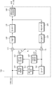
도 1은 영상 부호화 장치의 일 실시예에 따른 구성을 나타내는 블록도이다.
도 2는 영상 복호화 장치의 일 실시예에 따른 구성을 나타내는 블록도이다.
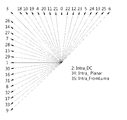
도 3은 인트라 예측의 각 모드를 설명하는 도면이다.
도 4는 인트라 예측 모드에서 현재 블록이 참조할 수 있는 샘플을 개략적으로 도시한 것이다.
도 5는 방향성 예측에 따른 레지듀얼 신호의 분포를 개략적으로 설명하는 도면이다.
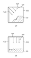
도 6은 본 발명이 적용되는 시스템에서 인트라 예측 모드에 따라 미리 정해진 제1 예측 영역과 제2 예측 영역의 예를 개략적으로 도시한 것이다.
도 7은 본 발명이 적용되는 시스템에서 인트라 예측의 일 예를 개략적으로 설명하는 순서도이다.
도 8은 본 발명이 적용되는 시스템에서 상술한 인트라 예측의 방법을 수행하는 부호화기의 동작을 개략적으로 설명하는 순서도이다.
도 9는 본 발명이 적용되는 시스템에서 상술한 인트라 예측의 방법을 수행하는 복호화기의 동작을 개략적으로 설명하는 순서도이다.
도 10은 부호화 영역(CU), 예측 영역(PU), 변환 영역(TU)의 분할 구조에 관한 일 예를 개략적으로 설명한 것이다.
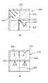
도 11은 본 발명이 적용되는 시스템에서, 현재 블록(부호화 대상 블록)을 예측 모드에 따라서 두 개의 예측 영역으로 분할하는 일 예를 개략적으로 도시한 것이다.
도 12는 본 발명이 적용되는 시스템에서, 현재 블록(부호화 대상 블록)을 예측 모드에 따라서 두 개의 예측 영역으로 분할하는 다른 예를 개략적으로 도시한 것이다.
도 13은 본 발명이 적용되는 시스템에서, 현재 블록(부호화 대상 블록)을 인트라 예측 모드에 따라서 3개의 예측 영역으로 분할하는 예들을 개략적으로 도시한 것이다.
도 14는 본 발명이 적용되는 시스템에서, 비정방형 변환 영역의 변환에 관한 예들을 개략적으로 나타낸 것이다.
도 15는 본 발명이 적용되는 시스템에서, 현재 블록 내 선순위 예측 영역과 후순위 예측 영역 사이의 상관성에 기반해서, 선순위 예측 영역의 복원된 샘플을 이용하여 후순위 예측 영역에 대한 예측을 수행하는 예들을 개략적으로 도시한 것이다.
도 16은 본 발명이 적용되는 시스템에서 현재 예측 영역의 예측 모드를 결정하는 예들을 개략적으로 도시한 것이다.1 is a block diagram showing a configuration of an image encoding apparatus according to an embodiment of the present invention.
2 is a block diagram illustrating a configuration of an image decoding apparatus according to an embodiment.
3 is a diagram illustrating each mode of intra prediction.
4 schematically illustrates a sample that the current block may refer to in the intra prediction mode.
5 is a diagram schematically illustrating a distribution of residual signals according to directional prediction.
FIG. 6 schematically illustrates an example of a first prediction region and a second prediction region predetermined according to an intra prediction mode in a system to which the present invention is applied.
7 is a flowchart schematically illustrating an example of intra prediction in a system to which the present invention is applied.
8 is a flowchart schematically illustrating an operation of an encoder for performing the above-described intra prediction method in a system to which the present invention is applied.
9 is a flowchart schematically illustrating an operation of a decoder for performing the above-described intra prediction method in a system to which the present invention is applied.
FIG. 10 schematically illustrates an example of a partition structure of a coding region CU, a prediction region PU, and a transform region TU.
FIG. 11 schematically illustrates an example of dividing a current block (coding target block) into two prediction regions according to a prediction mode in a system to which the present invention is applied.
12 schematically illustrates another example of dividing a current block (block to be encoded) into two prediction regions according to a prediction mode in a system to which the present invention is applied.
FIG. 13 schematically illustrates examples of dividing a current block (coding target block) into three prediction regions according to an intra prediction mode in a system to which the present invention is applied.
14 schematically illustrates examples of transforming a non-square transform region in a system to which the present invention is applied.
FIG. 15 schematically illustrates examples of performing prediction on a subordinate prediction region using a reconstructed sample of a priority prediction region based on a correlation between a priority prediction region and a subordinate prediction region in a current block in a system to which the present invention is applied. It is shown as.
FIG. 16 schematically illustrates examples of determining a prediction mode of a current prediction region in a system to which the present invention is applied.
이하, 도면을 참조하여 본 발명의 실시 형태에 대하여 구체적으로 설명한다. 본 명세서의 실시예를 설명함에 있어, 관련된 공지 구성 또는 기능에 대한 구체적인 설명이 본 명세서의 요지를 흐릴 수 있다고 판단되는 경우에는 그 상세한 설명은 생략한다.Hereinafter, embodiments of the present invention will be described in detail with reference to the drawings. In the following description of the embodiments of the present invention, a detailed description of known functions and configurations incorporated herein will be omitted when it may make the subject matter of the present disclosure rather unclear.
어떤 구성 요소가 다른 구성 요소에 “연결되어” 있다거나 “접속되어” 있다고 언급된 때에는, 그 다른 구성 요소에 직접적으로 연결되어 있거나 또는 접속되어 있을 수도 있으나, 중간에 다른 구성 요소가 존재할 수도 있다고 이해되어야 할 것이다. 아울러, 본 발명에서 특정 구성을 “포함”한다고 기술하는 내용은 해당 구성 이외의 구성을 배제하는 것이 아니며, 추가적인 구성이 본 발명의 실시 또는 본 발명의 기술적 사상의 범위에 포함될 수 있음을 의미한다. It is to be understood that when an element is referred to as being "connected" or "connected" to another element, it may be directly connected or connected to the other element, . In addition, the description of "including" a specific configuration in the present invention does not exclude a configuration other than the configuration, and means that additional configurations can be included in the practice of the present invention or the technical scope of the present invention.
제1, 제2 등의 용어는 다양한 구성요소들을 설명하는데 사용될 수 있지만, 상기 구성요소들은 상기 용어들에 의해 한정되어서는 안 된다. 상기 용어들은 하나의 구성요소를 다른 구성요소로부터 구별하는 목적으로만 사용된다. 예를 들어, 본 발명의 권리 범위를 벗어나지 않으면서 제1 구성요소는 제2 구성요소로 명명될 수 있고, 유사하게 제2 구성요소도 제1 구성요소로 명명될 수 있다.The terms first, second, etc. may be used to describe various components, but the components should not be limited by the terms. The terms are used only for the purpose of distinguishing one component from another. For example, without departing from the scope of the present invention, the first component may be referred to as a second component, and similarly, the second component may also be referred to as a first component.
또한 본 발명의 실시예에 나타나는 구성부들은 서로 다른 특징적인 기능들을 나타내기 위해 독립적으로 도시되는 것으로, 각 구성부들이 분리된 하드웨어나 하나의 소프트웨어 구성단위로 이루어짐을 의미하지 않는다. 즉, 각 구성부는 설명의 편의상 각각의 구성부로 나열하여 포함한 것으로 각 구성부 중 적어도 두 개의 구성부가 합쳐져 하나의 구성부로 이루어지거나, 하나의 구성부가 복수 개의 구성부로 나뉘어져 기능을 수행할 수 있고 이러한 각 구성부의 통합된 실시예 및 분리된 실시예도 본 발명의 본질에서 벗어나지 않는 한 본 발명의 권리범위에 포함된다.In addition, the components shown in the embodiments of the present invention are shown independently to represent different characteristic functions, which does not mean that each component is composed of separate hardware or software constituent units. That is, each constituent unit is included in each constituent unit for convenience of explanation, and at least two constituent units of the constituent units may be combined to form one constituent unit, or one constituent unit may be divided into a plurality of constituent units to perform a function. The integrated embodiments and separate embodiments of the components are also included within the scope of the present invention, unless they depart from the essence of the present invention.
또한, 일부의 구성 요소는 본 발명에서 본질적인 기능을 수행하는 필수적인 구성 요소는 아니고 단지 성능을 향상시키기 위한 선택적 구성 요소일 수 있다. 본 발명은 단지 성능 향상을 위해 사용되는 구성 요소를 제외한 본 발명의 본질을 구현하는데 필수적인 구성부만을 포함하여 구현될 수 있고, 단지 성능 향상을 위해 사용되는 선택적 구성 요소를 제외한 필수 구성 요소만을 포함한 구조도 본 발명의 권리범위에 포함된다.
In addition, some of the components are not essential components to perform essential functions in the present invention, but may be optional components only to improve performance. The present invention can be implemented only with components essential for realizing the essence of the present invention, except for the components used for the performance improvement, and can be implemented by only including the essential components except the optional components used for performance improvement Are also included in the scope of the present invention.
도 1은 영상 부호화 장치의 일 실시예에 따른 구성을 나타내는 블록도이다. 1 is a block diagram showing a configuration of an image encoding apparatus according to an embodiment of the present invention.
도 1을 참조하면, 상기 영상 부호화 장치(100)는 움직임 예측부(110), 움직임 보상부(115), 인트라 예측부(120), 감산기(125), 변환부(130), 양자화부(135), 엔트로피 부호화부(140), 역양자화부(145), 역변환부(150), 가산기(155), 필터부(160) 및 참조영상 버퍼(165)를 포함한다.Referring to FIG. 1, the
영상 부호화 장치(100)는 입력 영상에 대해 인트라(intra) 모드 또는 인터(inter) 모드로 부호화를 수행하고 비트 스트림(bit stream)을 출력할 수 있다. 인트라 모드인 경우에는 인트라 예측부(120)에서 예측이 수행되고, 인터 모드의 경우에는 움직임 예측부(110), 움직임 보상부(115) 등을 통해서 예측이 수행될 수 있다. 영상 부호화 장치(100)는 입력 영상의 입력 블록에 대한 예측 블록을 생성한 후, 입력 블록과 예측 블록의 차분을 부호화할 수 있다.The
인트라 모드인 경우, 인트라 예측부(120)는 현재 블록 주변의 이미 부호화된 블록의 화소값을 이용하여 공간적 예측을 수행하여 예측 블록을 생성할 수 있다.In the intra mode, the
인터 모드인 경우, 움직임 예측부(110)는, 움직임 예측 과정에서 참조 영상 버퍼(165)에 저장되어 있는 참조 영상에서 입력 블록과 가장 매치가 잘 되는 영역을 찾아 움직임 벡터를 구할 수 있다. 움직임 보상부(115)는 움직임 벡터와 참조 영상 버퍼(165)에 저장되어 있는 참조 영상을 이용하여 움직임 보상을 수행함으로써 예측 블록을 생성할 수 있다. In the inter mode, the
감산기(125)는 입력 블록과 생성된 예측 블록의 차분에 의해 레지듀얼 블록(residual block)을 생성할 수 있다. 변환부(130)는 레지듀얼 블록에 대해 변환(transform)을 수행하여 변환 계수(transform coefficient)를 출력할 수 있다. 레지듀얼 신호는 원신호와 예측 신호의 차이를 의미할 수 있고, 또한 원신호와 예측 신호의 차이가 변환(transform)된 형태의 신호 또는 원신호와 예측 신호의 차이가 변환되고 양자화된 형태의 신호를 의미할 수도 있다. 레지듀얼 신호를 블록 단위에서는 레지듀얼 블록이라 할 수 있다.The
양자화부(135)는 변환 계수를 양자화 파라미터에 따라 양자화한 양자화 계수(quantized coefficient)를 출력할 수 있다. The
엔트로피 부호화부(140)는, 양자화부(135)에서 산출된 값들 또는 부호화 과정에서 산출된 부호화 파라미터 값 등에 대응하는 심볼(symbol)을 확률 분포에 따라 엔트로피 부호화하여 비트 스트림(bit stream)을 출력할 수 있다. The
엔트로피 부호화가 적용되는 경우, 높은 발생 확률을 갖는 심볼에 적은 수의 비트가 할당되고 낮은 발생 확률을 갖는 심볼에 많은 수의 비트가 할당되도록 함으로써 영상 부호화의 압축 성능을 높일 수 있다. When entropy encoding is applied, the compression performance of image encoding may be improved by assigning a small number of bits to a symbol having a high occurrence probability and a large number of bits to a symbol having a low occurrence probability.
엔트로피 부호화를 위해 CAVLC(Context-Adaptive Variable Length Coding), CABAC(Context-Adaptive Binary Arithmetic Coding) 등과 같은 부호화 방법이 사용될 수 있다. 예를 들어, 엔트로피 부호화부(140)에는 가변 길이 부호화(VLC: Variable Lenghth Coding/Code) 테이블을 사용하여 엔트로피 부호화를 수행할 수 있다. 엔트로피 부호화부(140)는 대상 심볼의 이진화(binarization) 방법 및 대상 심볼/빈(bin)의 확률 모델(probability model)을 도출한 후, 도출된 이진화 방법 또는 확률 모델을 사용하여 엔트로피 부호화를 수행할 수도 있다.Encoding methods such as context-adaptive variable length coding (CAVLC) and context-adaptive binary arithmetic coding (CABAC) may be used for entropy encoding. For example, the
양자화된 계수는 역양자화부(145)에서 역양자화되고 역변환부(150)에서 역변환될 수 있다. 역양자화되고, 역변환된 계수는 복원된 레지듀얼 블록(reconstructed residual block)으로 생성 되며, 가산기(155)는 예측 블록과 복원된 레지듀얼 블록을 이용하여 복원 블록을 생성할 수 있다. The quantized coefficient may be inversely quantized by the
필터부(160)는 디블록킹 필터(deblocking filter), SAO(Sample Adaptive Offset), ALF(Adaptive Loop Filter) 중 적어도 하나 이상을 복원 블록 또는 복원 픽쳐에 적용할 수 있다. 필터부(160)를 거친 복원 블록은 참조 영상 버퍼(165)에 저장될 수 있다.The
도 2는 영상 복호화 장치의 일 실시예에 따른 구성을 나타내는 블록도이다. 2 is a block diagram illustrating a configuration of an image decoding apparatus according to an embodiment.
도 2를 참조하면, 상기 영상 복호화 장치(200)는 엔트로피 복호화부(210), 역양자화부(220), 역변환부(230), 인트라 예측부(240), 움직임 보상부(250), 필터부(260), 참조 영상 버퍼(270) 및 가산기(280)를 포함한다.2, the
영상 복호화 장치(200)는 부호화기에서 출력된 비트 스트림을 입력 받아 인트라 모드 또는 인터 모드로 복호화를 수행하고 재구성된 영상, 즉 복원 영상을 출력할 수 있다. 인트라 모드인 경우에는 인트라 예측부(240)에서 예측이 수행되고, 인터 모드인 경우에는 움직임 보상부(250)를 통해서 예측이 수행될 수 있다. 영상 복호화 장치(200)는 입력 받은 비트스트림으로부터 복원된 레지듀얼 블록(residual block)을 얻고 예측 블록을 생성한 후 복원된 레지듀얼 블록과 예측 블록을 더하여 재구성된 블록, 즉 복원 블록을 생성할 수 있다.The
엔트로피 복호화부(210)는, 입력된 비트 스트림을 확률 분포에 따라 엔트로피 복호화하여 양자화된 계수(quantized coefficient) 형태의 심볼들을 생성할 수 있다. 엔트로피 복호화 방법은 상술한 엔트로피 부호화 방법에 대응하여 수행될 수 있다. The
양자화된 계수는 역양자화부(220)에서 역양자화되고 역변환부(230)에서 역변환되며, 양자화된 계수가 역양자화/역변환 된 결과 복원된 레지듀얼 블록(residual block)이 생성될 수 있다. The quantized coefficients are inversely quantized by the
인트라 모드인 경우, 인트라 예측부(240)는 현재 블록 주변의 이미 복호화된 블록의 화소값을 이용하여 공간적 예측을 수행하여 예측 블록을 생성할 수 있다. 인터 모드인 경우, 움직임 보상부(250)는 움직임 벡터 및 참조 영상 버퍼(270)에 저장되어 있는 참조 영상을 이용하여 움직임 보상을 수행함으로써 예측 블록을 생성할 수 있다. In the intra mode, the
가산기(280)는 복원된 레지듀얼 블록과 예측 블록을 기반으로 복원 블록을 생성할수 있다. 필터부(260)는 디블록킹 필터, SAO, ALF 중 적어도 하나 이상을 복원 블록에 적용할 수 있다. 필터부(260)는 재구성된 영상, 즉 복원 영상을 출력한다. 복원 영상은 참조 영상 버퍼(270)에 저장되어 화면 간 예측에 사용될 수 있다.
The
상술한 인트라 예측 모드에서는 하나 이상의 복원된 참조 샘플을 이용하여 방향성 예측 또는 비방향성 예측을 수행한다. In the above-described intra prediction mode, directional prediction or non-directional prediction is performed using one or more reconstructed reference samples.
도 3은 인트라 예측의 각 모드를 설명하는 도면이다. 도 3을 참조하면, DC 모드(Intra_DC), 플래너 모드(Intra_Planar), 루마 모드를 크로마에 적용하는 모드(Intra_FromLuma)를 제외하고, 0, 1, 3~33의 모드가 방향에 따라서 정의되어 있는 것을 확인할 수 있다. 3 is a diagram illustrating each mode of intra prediction. Referring to FIG. 3, except for the DC mode Intra_DC, the planner mode Intra_Planar, and the mode In_FromLuma that applies the luma mode to the chroma,
도 3에 도시된 각 예측 모드 중에서 현재 블록의 예측에 사용될 수 있는 모드의 개수는 현재 블록의 크기에 따라 정해질 수 있다. The number of modes that can be used for prediction of the current block among each prediction mode illustrated in FIG. 3 may be determined according to the size of the current block.
표 1은 현재 블록의 크기에 따라 사용 가능한 예측 모드의 개수에 관한 일 예를 나타낸 것이다.Table 1 shows an example of the number of prediction modes available according to the size of the current block.
<표 1>TABLE 1

이때, 예측 대상 블록, 즉 현재 블록의 크기는 표 1에 예시된 2x2, 4x4,8x8, 16x16, 32x32, 64x64 등의 정사각형뿐만 아니라, 2x8, 4x8, 2x16, 4x16, 8x16 등의 직사각형 블록이 될 수도 있다. In this case, the size of the prediction target block, that is, the current block, may be not only squares such as 2x2, 4x4, 8x8, 16x16, 32x32, and 64x64, but also rectangular blocks such as 2x8, 4x8, 2x16, 4x16, and 8x16. have.
예측 대상 블록의 크기는 부호화 영역(Coding Unit: CU), 예측 영역(Prediction Unit: PU), 변환 영역(Transform Unit: TU) 중 적어도 하나의 크기가 될 수 있다.The size of the prediction target block may be at least one of a coding unit (CU), a prediction unit (PU), and a transform unit (TU).
인트라 예측에서는 도 3에 도시된 바와 같은 각 모드에 따라서, 참조 샘플의 정보를 이용할 수 있다. In intra prediction, information of a reference sample may be used according to each mode as shown in FIG. 3.
도 4는 인트라 예측 모드에서 현재 블록이 참조할 수 있는 샘플을 개략적으로 도시한 것이다. 도 4를 참조하면, 현재 블록(C, 410)에 인트라 예측이 적용되는 경우에, 현재 블록(410) 주변의 복원된 참조 샘플, 즉, 상좌측(above_left) 참조 샘플(420), 상측(above) 참조 샘플(430), 상우측(above_right) 참조 샘플(440), 좌측(left) 참조 샘플(450), 하좌측(below_left) 참조 샘플(460) 중에서 예측 모드에 따라 선택된 참조 샘플이 현재 블록(410)의 예측에 이용될 수 있다.4 schematically illustrates a sample that the current block may refer to in the intra prediction mode. Referring to FIG. 4, when intra prediction is applied to the current blocks C and 410, a reconstructed reference sample around the
예컨대, 현재 블록(410)의 예측 모드가 도 3에서 모드 0(mode=0)의 수직 방향 모드인 경우에, 현재 블록(410)의 상측(above) 참조 샘플(430)을 이용할 수 있다. 현재 블록(410)의 예측 모드가 모드 1(mode=1)의 수평 방향 모드인 경우에는, 현재 블록(410)의 좌측(left) 참조 샘플(450)을 사용할 수 있다. For example, when the prediction mode of the
또한, 현재 블록(410)의 예측 모드가 모드 13(mode=13)인 경우에는 상측(above) 참조 샘플(430) 또는 상우측(above_right) 참조 샘플(440)을 이용할 수 있다. 마찬가지로, 현재 블록(410)의 예측 모드가 모드 7(mode=7)인 경우에는, 좌측(left) 참조 샘플(450) 또는 하좌측(below_left) 참조 샘플(460)을 이용할 수 있다.In addition, when the prediction mode of the
상술한 바와 같이, 인트라 예측에 사용되는 방향성 예측(인트라 예측 모드, 0, 1, 3~33)에 있어서는 예측 방향에 따라, 즉 예측 모드에 따라 예측 기반 픽셀 값(참조 샘플 값)을 직접 예측 값으로 사용하거나 예측 기반 픽셀 값의 평균값을 예측 값으로 사용한다. 또한, 예측 영역의 분할과는 별개로 변환 영역을 분할해 본 후 변환 영역의 분할 구조를 시그널링 하는 RQT(Residual Quadtree) 방식을 이용할 수 있다. 하지만, 이 경우에는 인트라 예측 모드에 따라 레지듀얼 신호의 분포가 달라지는 특성을 이용하지 못한다. 따라서, 부호화 효율의 향상이 제한적이며, 최적 변환 영역 분할 구조를 판단하기 위해서는 부호화기의 복잡도가 증가하게 된다.As described above, in the directional prediction (intra prediction mode, 0, 1, 3 to 33) used for intra prediction, the prediction based pixel value (reference sample value) is directly predicted according to the prediction direction, that is, according to the prediction mode. Or use the average of the prediction-based pixel values as the prediction value. In addition, after splitting the transform region separately from the partitioning of the prediction region, a residual quadtree (RQT) method for signaling the partition structure of the transform region may be used. However, in this case, the characteristic that the distribution of the residual signal varies according to the intra prediction mode cannot be used. Therefore, the improvement of the coding efficiency is limited, and the complexity of the encoder increases in order to determine the optimal transform region partition structure.
구체적으로, 영상 정보의 부호화/복호화에 사용되는 방향성 예측은 참조 샘플로부터의 거리가 멀어질수록 예측의 정확도가 떨어지게 된다.In detail, in the directional prediction used for encoding / decoding the image information, the accuracy of the prediction decreases as the distance from the reference sample increases.
도 5는 방향성 예측에 따른 레지듀얼 신호의 분포를 개략적으로 설명하는 도면이다. 5 is a diagram schematically illustrating a distribution of residual signals according to directional prediction.
도 5(A)는 좌상측으로부터 우하측 방향으로의 대각 예측이 수행되는 경우의 레지듀얼 신호 분포를 개략적으로 도시한 것이다. 도 5(A)의 예에서는, 예측 대상 블록인 현재 블록(500)에 인트라 예측 모드가 적용되며, 참조 샘플(510, 520)을 이용하여 우하측 방향의 예측(530)이 수행되고 있다. 도시된 바와 같이, 레지듀얼 신호(540)는 참조 샘플로부터 먼 우하측 방향에 많이 분포한다. FIG. 5A schematically shows the residual signal distribution when diagonal prediction from the upper left side to the lower right direction is performed. In the example of FIG. 5A, the intra prediction mode is applied to the
도 5(B)는 수직 방향으로 예측이 수행되는 경우의 레지듀얼 신호 분호를 개략적으로 도시한 것이다. 도 5(B)의 예에서는, 예측 대상 블록인 현재 블록(550)에 인트라 예측 모드가 적용되며, 참조 샘플(560, 570) 중 상측의 참조 샘플(560)을 이용하여 수직 방향의 예측(580)이 수행되고 있다. 도시된 바와 같이, 레지듀얼 신호(540)는 상측의 참조 샘플(560)로부터 먼 곳에 분포한다. FIG. 5B schematically illustrates residual signal division when prediction is performed in the vertical direction. In the example of FIG. 5B, the intra prediction mode is applied to the
도 5(A) 및 도 5(B)에 도시된 바와 같이, 일반적으로 레지듀얼 신호의 크기는 참조 샘플로부터 멀어질수록 커지게 된다. 또한, 레지듀얼 신호의 분포는 예측 모드에 따라 달리 분포하게 된다.As shown in Figs. 5A and 5B, in general, the magnitude of the residual signal increases as the distance from the reference sample increases. In addition, the distribution of the residual signal is distributed differently according to the prediction mode.
상술한 바와 같이, 방향성 예측에 있어서, 예측의 정확도는 참조 샘플로부터 멀어질수록 떨어지게 된다. 따라서, 참조 샘플로부터 멀어질수록 레지듀얼 신호의 크기가 커지고 레지듀얼 신호가 많이 분포한다는 것을 고려할 때, 인트라 예측의 방향에 따라, 레지듀얼 신호가 많이 분포할 것으로 추정되는 영역에 대해서는 더 가까이에 있는 복원 샘플을 참조 샘플로 사용하도록 함으로써, 예측 효율을 더 높일 수 있다. As described above, in the directional prediction, the accuracy of the prediction becomes farther away from the reference sample. Therefore, considering that the residual signal is larger and the residual signal is larger as the distance from the reference sample increases, it is closer to the region where the residual signal is expected to be distributed according to the direction of intra prediction. By using the reconstructed sample as a reference sample, the prediction efficiency can be further improved.
이때, 레지듀얼 신호가 많이 분포하는 영역을 인트라 예측 모드에 따라서 결정할 수 있다. 인트라 예측 모드에 따라 레지듀얼 신호의 분호 영역을 결정함으로써, 영역 분할의 정보를 별도로 부호화하는데 필요한 시그널링의 오버헤드를 줄일 수 있을 뿐만 아니라, 영역 분할의 구조를 판단하는데 필요한 복잡도를 최소화할 수 있다.In this case, an area in which the residual signal is widely distributed may be determined according to the intra prediction mode. By determining the decoded region of the residual signal according to the intra prediction mode, the signaling overhead required for separately encoding the information of the region division can be reduced, and the complexity required to determine the structure of the region division can be minimized.
본 명세서에서는 레지듀얼 신호가 많이 분포할 것으로 추정되는 영역을, 설명의 편의를 위해 ‘제2 예측 영역’이라 하고, 현재 블록에서 제2 예측 영역이 아닌 영역, 즉 레지듀얼 신호가 많이 분포하지 않는 것으로 추정되는 영역을 ‘제1 예측 영역’이라 한다. In the present specification, an area where a large number of residual signals are estimated to be distributed is referred to as a 'second prediction area' for convenience of description, and an area other than the second prediction area, that is, the residual signal is not distributed much in the current block. The region estimated to be referred to as a 'first prediction region'.
이때, 현재 블록 내에서 소정의 기준치 이상의 크기를 가지는 레지듀얼 신호가 분포하는 영역을 제2 예측 영역으로 설정할 수 있다. 또한, 각 예측 모드에 따라서 미리 정해진 소정의 영역이 제2 예측 영역으로 설정될 수도 있다. 예컨대, 각 예측 모드에서 참조하는 샘플로부터 현재 블록 내에서 가장 먼 곳에 위치하는 영역이 제2 예측 블록으로 설정될 수 있다. In this case, an area in which a residual signal having a magnitude greater than or equal to a predetermined reference value is distributed in the current block may be set as a second prediction area. In addition, a predetermined area may be set as the second prediction area according to each prediction mode. For example, a region located farthest in the current block from a sample referred to in each prediction mode may be set as the second prediction block.
또한, 이때, 제2 예측 영역은 후술하는 도면들에 도시되는 바와 같이, 변환 영역과 동일한 크기를 갖도록 할 수도 있다.In this case, the second prediction region may have the same size as the transform region, as shown in the following drawings.
도 6은 본 발명이 적용되는 시스템에서 인트라 예측 모드에 따라 미리 정해진 제1 예측 영역과 제2 예측 영역의 예를 개략적으로 도시한 것이다. 도 6(A)와 도 6(B)의 예에서, 변환 블록은 예측 대상 블록(현재 블록)의 4분의 1 크기가 되도록 설정되어 있다. FIG. 6 schematically illustrates an example of a first prediction region and a second prediction region predetermined according to an intra prediction mode in a system to which the present invention is applied. In the examples of Figs. 6A and 6B, the transform block is set to be one-fourth the size of the prediction target block (the current block).
도 6(A)를 참조하면, 현재 블록(600)의 제1 예측 영역(610)에 대해서, 현재 블록(600) 주변의 복원된 참조 샘플(605)을 이용하여 인트라 예측을 수행한다. 도 6(A)의 예에서는, 현재 블록(600)의 제1 예측 영역(610)에는 우하측 방향의 예측 모드(615)가 적용되고 있다. Referring to FIG. 6A, intra prediction is performed on the
도 6(A)에서는 제1 예측 영역(610)에 대한 예측 및 변환/복원을 수행한 후, 제2 예측 영역(620)의 예측에 대해서는 복원된 제1 예측 영역의 샘플(625)을 이용함으로써 잔여 신호가 많이 발생할 것으로 추정된 제2 예측 영역(620)의 부호화 효율을 높일 수 있다. 제2 예측 영역(620)에 대한 예측 모드(630)는 제1 예측 영역(610)에 대한 복원이 수행된 후에 결정될 수 있다.In FIG. 6A, after the prediction and the transform / restore of the
도 6(B)를 참조하면, 현재 블록(640)의 제1 예측 영역(650)에 대해서, 현재 블록(640) 주변의 복원된 참조 샘플(645)을 이용하여 인트라 예측을 수행한다. 도 6(B)의 예에서는, 현재 블록(640)의 제1 예측 영역(640)에는 수직 방향의 예측 모드(655)가 적용되고 있다. Referring to FIG. 6B, intra prediction is performed on the
도 6(B)에서는 제1 예측 영역(650)에 대한 예측 및 변환/복원을 수행한 후, 제2 예측 영역(660)의 예측에 대해서는 복원된 제1 예측 영역의 샘플(665)을 이용함으로써 잔여 신호가 많이 발생할 것으로 추정된 제2 예측 영역(660)의 부호화 효율을 높일 수 있다. 제2 예측 영역(660)에 대한 예측 모드(670)는 제1 예측 영역(650)에 대한 복원이 수행된 후에 결정될 수 있다.In FIG. 6B, after the prediction and the transformation / reconstruction of the
예측 영역을 제1 예측 영역과 제2 예측 영역 외에 추가로 분할하는 경우에는, 상술한 바와 같이, 제1 예측 영역에 대한 예측/변환/복원 후에 제2 예측 영역에 대한 예측을 복원된 제1 예측 영역의 샘플을 이용하여 수행하는 가정을 순차적으로 반복할 수 있다. 예컨대, 제2 예측 영역을 분할한 제3 예측 영역의 경우 또는 제1 예측 영역을 제2 예측 영역과 제3 예측 영역으로 분할한 경우에, 제3 예측 영역에 대한 예측은 복원된 제2 예측 영역의 샘플을 이용하여 수행할 수 있다. When the prediction region is further partitioned in addition to the first prediction region and the second prediction region, as described above, the first prediction reconstructing the prediction for the second prediction region after the prediction / transformation / reconstruction of the first prediction region. The assumptions made using a sample of the region can be repeated sequentially. For example, in the case of the third prediction region obtained by dividing the second prediction region or when the first prediction region is divided into the second prediction region and the third prediction region, the prediction for the third prediction region is reconstructed in the second prediction region. Can be performed using a sample of
본 명세서에서 ‘예측 영역’이라 함은, 다양한 인트라 예측 모드에 따라 화소값 예측이 수행되는 영역을 지칭한다. 또한, 본 명세서에서 ‘변환 영역’이라 함은 예측 영역의 일부 혹은 전부로 구성되고, 자기 자신을 포함하는 예측 영역과 동일한 예측 모드를 가지면서 변환 부호화를 통해 샘플값 복원이 수행되는 영역을 지칭한다. In the present specification, the term “prediction area” refers to an area where pixel value prediction is performed according to various intra prediction modes. In addition, in the present specification, the term 'transform region' refers to a region that is configured as part or all of the prediction region, and has a same prediction mode as that of the prediction region including itself, and performs sample value reconstruction through transform coding. .
도 7은 본 발명이 적용되는 시스템에서 인트라 예측의 일 예를 개략적으로 설명하는 순서도이다. 도 7의 인트라 예측 방법은 부호화기에서 수행될 수도 있고, 복호화기에서 수행될 수도 있다.7 is a flowchart schematically illustrating an example of intra prediction in a system to which the present invention is applied. The intra prediction method of FIG. 7 may be performed by an encoder or may be performed by a decoder.
도 7을 참조하면, 현재 블록에 대하여 인트라 예측 모드에 따라서, 예측 영역을 두 개 이상으로 분할한다(S710). Referring to FIG. 7, a prediction area is divided into two or more according to an intra prediction mode with respect to a current block (S710).
이어서, 인트라 예측 모드에 따라서, 변환 영역을 두 개 이상으로 분할한다(S720). Next, according to the intra prediction mode, the transform region is divided into two or more (S720).
인트라 예측 모드에 따라서 예측 영역과 변환 영역의 처리 순서를 결정한다(S730).The processing order of the prediction region and the transform region is determined according to the intra prediction mode (S730).
이렇게 결정된 처리 순서에 따라서, 첫 번째 예측 영역(제1 예측 영역)에 대한 인트라 예측/복원을 수행한다(S740). In accordance with the processing sequence thus determined, intra prediction / restore of the first prediction region (first prediction region) is performed (S740).
첫 번째 예측 영역을 복원한 후에는, 처리 순서에 따라서 두 번째 예측 영역(제2 예측 영역)에 대한 인트라 예측/복원을 수행한다(S750).After reconstructing the first prediction region, intra prediction / restore of the second prediction region (second prediction region) is performed according to the processing order (S750).
도 8은 본 발명이 적용되는 시스템에서 상술한 인트라 예측의 방법을 수행하는 부호화기의 동작을 개략적으로 설명하는 순서도이다.8 is a flowchart schematically illustrating an operation of an encoder for performing the above-described intra prediction method in a system to which the present invention is applied.
도 8을 참조하면, 부호화기는 복수의 예측 영역에 대하여 최적 예측 모드를 결정한다(S810). 최적 예측 모드를 결정하는 방법을 현재 블록 내에서 예측 모드별로 미리 정해놓은 n 번째 예측 영역을 대상으로 설명하면, 예측 모드별로 미리 정해놓은 변환 영역의 구조 및 변환/복원의 순서에 따라 예측 및 변환/복원을 수행한다. 또한, n 번째 예측 영역에 대한 예측 오차 및/또는 예측 비트량을 계산하고, 이를 토대로 n 번째 예측 영역에 대한 최적의 인트라 예측 모드를 결정할 수 있다. Referring to FIG. 8, the encoder determines an optimal prediction mode for a plurality of prediction regions (S810). The method of determining the optimal prediction mode is described in terms of the nth prediction region predetermined for each prediction mode in the current block, and the prediction and transformation / Perform a restore. In addition, a prediction error and / or a prediction bit amount for the n th prediction region may be calculated, and an optimal intra prediction mode for the n th prediction region may be determined based on the prediction error and / or the prediction bit amount.
현재 블록에 대한 분할 구조 및 처리 순서를 결정한다(S820). S810에서 결정된 현재 블록의 첫 번째(n=1) 예측 영역에 대한 최적 인트라 예측 모드에 따라서 현재 블록에 대한 예측 영역과 변환 영역의 분할 구조, 예측 영역과 변환 영역의 처리 순서를 결정한다. 현재 블록에 대한 예측 영역과 변환 영역의 분할 구조와 함께 전체 예측 영역의 개수 N을 결정할 수 있다. The partition structure and the processing order for the current block are determined (S820). According to the optimal intra prediction mode for the first (n = 1) prediction region of the current block determined in S810, the partition structure of the prediction region and the transform region for the current block, and the processing order of the prediction region and the transform region are determined. The number N of all prediction regions may be determined together with the partition structure of the prediction region and the transform region for the current block.
이어서, 예측 영역의 인트라 예측 모드를 시그널링 한다(S830). n번째 예측 영역의 최적 인트라 예측 모드를 시그널링 한다. 두 번째 이후(n>1)의 예측 영역의 예측에 사용 가능한 예측 모드들과, 두 번째 이후(n>1) 예측 영역의 복원된 영역 중 n 번째 예측 영역과 인접한 영역의 예측 모드들을 활용하여, n 번째 예측 영역의 예측을 위한 예측 모드 후보(들)을 결정할 수 있다.Subsequently, an intra prediction mode of the prediction region is signaled (S830). Signal an optimal intra prediction mode of the n th prediction region. By utilizing the prediction modes available for the prediction of the second (n> 1) prediction region and the prediction modes of the region adjacent to the nth prediction region of the reconstructed region of the second after (n> 1) prediction region, Prediction mode candidate (s) for prediction of the n th prediction region may be determined.
예측 영역에 대한 변환 부호화를 수행한다(S840). n 번째 예측 영역에 속한 각 변환 영역(들)에 대하여, 상기 S820 단계에서 결정된 변환 영역의 분할 구조 및 처리 순서에 따라, n 번째 예측 영역의 최적 인트라 예측 모드에 따른 예측 오차 신호에 대해 각 변환 영역의 변환 계수를 부호화함으로써 n 번째 예측 영역에 대한 변환 부호화를 수행할 수 있다.The transform encoding on the prediction region is performed (S840). For each transform region (s) belonging to the n th prediction region, each transform region for the prediction error signal according to the optimal intra prediction mode of the n th prediction region, according to the partition structure and the processing order of the transform region determined in step S820. By encoding the transform coefficient of, transform encoding on the n th prediction region may be performed.
전체 예측 영역(n==N)에 대하여 상술한 각 단계를 수행하였으면, 상기 각 단계의 수행을 종료한다. 아직 전체 예측 영역에 대하여 상기 단계들을 수행하지 않았으면(n<N), 다음 예측 영역(즉, n=n+1인 예측 영역)에 대하여 S810 단계부터 이하의 단계를 다시 수행할 수 있다. If the above-described steps are performed on the entire prediction region (n == N), the performance of each step is terminated. If the above steps are not yet performed for the entire prediction region (n <N), the following steps may be performed again from step S810 for the next prediction region (that is, the prediction region where n = n + 1).
따라서, 도 8의 전체 단계는 제1 예측 영역(첫 번째 예측 영역)에서부터 제2 예측 영역(두 번째 예측 영역), 이어서 제3 예측 영역(세 번째 예측 영역)의 순으로 진행될 수 있다. 이때, 첫 번째 예측 영역에 대한 단계인 S820 단계는 제2 예측 영역부터는 수행되지 않을 수 있다.Accordingly, the entire step of FIG. 8 may be performed in order of the first prediction region (the first prediction region), the second prediction region (the second prediction region), and then the third prediction region (the third prediction region). In this case, step S820, which is a step for the first prediction area, may not be performed from the second prediction area.
도 9는 본 발명이 적용되는 시스템에서 상술한 인트라 예측의 방법을 수행하는 복호화기의 동작을 개략적으로 설명하는 순서도이다.9 is a flowchart schematically illustrating an operation of a decoder for performing the above-described intra prediction method in a system to which the present invention is applied.
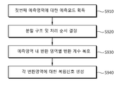
도 9를 참조하면, 복호화기는 부호화기로부터 수신한 비트 스트림을 파싱하여, 첫 번째 예측 영역(제1 예측 영역)에 대한 예측 모드를 획득한다(S910). Referring to FIG. 9, the decoder parses a bit stream received from an encoder to obtain a prediction mode for a first prediction region (first prediction region) (S910).
복호화기는 현재 블록에 대한 분할 구조 및 처리 순서를 결정한다(S920). 복호화기는 S910 단계에서 획득한 예측 모드에 따라서 현재 블록(복호 대상 블록)에 대한 예측 영역 및 변환 영역의 분할 구조 그리고 예측 영역 및 변환 영역의 처리 순서를 결정한다. 예측 영역 및 변환 영역의 분할 구조와 함께 전체 예측 영역의 개수 N을 결정할 수 있다. The decoder determines the partition structure and the processing order for the current block (S920). The decoder determines the partition structure of the prediction region and the transform region for the current block (block to be decoded) and the processing order of the prediction region and the transform region according to the prediction mode obtained in step S910. The number N of all prediction regions may be determined together with the partition structure of the prediction region and the transform region.
예측 영역 내의 변환 영역별로 변환 계수를 복호화한다(S930). 예컨대, 현재 블록에 N 개의 예측 영역별로, 예측 영역에 속하는 각 변환 영역의 변환 계수를 비트 스트림으로부터 파싱하여 복호화할 수 있다. 제2 예측 영역(두 번째 예측 영역) 이후의 예측 영역에 대해서는, 제1 예측 영역(첫 번째 예측 영역)의 예측에 사용 가능한 예측 모드들과, 제1 예측 영역(첫 번째 예측 영역)을 제외하고 이미 복원된 예측 영역 중 n 번째 예측 영역과 인접한 영역의 예측 모드들을 활용하여, n 번째 예측 영역의 예측을 위한 예측 모드 후보(들)을 결정할 수 있다.The transform coefficients are decoded for each transform region in the prediction region (S930). For example, transform coefficients of each transform region belonging to the prediction region may be parsed and decoded from the bit stream for each N prediction regions in the current block. For the prediction region after the second prediction region (second prediction region), the prediction modes available for the prediction of the first prediction region (first prediction region) and the first prediction region (first prediction region) are excluded. Prediction mode candidate (s) for prediction of the nth prediction region may be determined by using prediction modes of the region adjacent to the nth prediction region among the reconstructed prediction regions.
이후, 각 변환 영역에 대한 복원 신호를 생성한다(S940). n 번째 예측 영역에 대하여 살펴보면, n 번째 예측 영역에 속하는 각 변환 영역(들)에 대하여, 상기 S910 단계에서 결정된 변환 영역의 분할 구조 및 처리 순서에 따라서 각 변환 영역의 변환 계수를 역변환하여 레지듀얼 신호를 복원한다. 복원된 레지듀얼 신호와 n 번째 예측 영역에 대한 예측 모드에 따라서 수행된 예측 결과를 합산하여, 각 변환 영역에 대한 복원 신호를 생성함으로써 n 번째 예측 영역을 복원할 수 있다.Thereafter, a reconstruction signal for each transform region is generated (S940). Referring to the n th prediction region, for each transform region (s) belonging to the n th prediction region, a residual signal is obtained by inversely transforming transform coefficients of each transform region according to the partition structure and the processing order of the transform region determined in step S910. Restore it. The n th prediction region may be reconstructed by generating a reconstruction signal for each transform region by adding the reconstructed residual signal and the prediction result performed according to the prediction mode for the n th prediction region.
전체 예측 영역(n==N)에 대하여 상술한 각 단계를 수행하였으면, 상기 각 단계의 수행을 종료한다. 아직 전체 예측 영역에 대하여 상기 단계들을 수행하지 않았으면(n<N), 다음 예측 영역(즉, n=n+1인 예측 영역)에 대하여 S910 단계부터 이하의 단계를 다시 수행할 수 있다. If the above-described steps are performed on the entire prediction region (n == N), the performance of each step is terminated. If the above steps are not yet performed for the entire prediction region (n <N), the following steps may be performed again from the step S910 for the next prediction region (that is, the prediction region where n = n + 1).
따라서, 도 9의 전체 단계는 제1 예측 영역(첫 번째 예측 영역)에서부터 제2 예측 영역(두 번째 예측 영역), 이어서 제3 예측 영역(세 번째 예측 영역)의 순으로 진행될 수 있다. 이때, 첫 번째 예측 영역에 대한 단계인 S930 단계는 제2 예측 영역부터는 수행되지 않을 수 있다.Accordingly, the entire step of FIG. 9 may be performed in the order of the first prediction region (first prediction region), the second prediction region (second prediction region), and then the third prediction region (third prediction region). In this case, step S930, which is a step for the first prediction region, may not be performed from the second prediction region.
도 10은 부호화 영역(CU), 예측 영역(PU), 변환 영역(TU)의 분할 구조에 관한 일 예를 개략적으로 설명한 것이다.FIG. 10 schematically illustrates an example of a partition structure of a coding region CU, a prediction region PU, and a transform region TU.
도 10에서는, 가장 위쪽의 열부터 차례대로 64x64 사이즈의 부호화 영역(1010), 32x32 사이즈의 부호화 영역(1020), 16x16 사이즈의 부호화 영역(1030), 8x8 사이즈의 부호화 영역(1040)에 대한 분할 예를 개략적으로 도시하고 있다. In Fig. 10, examples of divisions of a 64x64
도 10을 참조하면, 각 부호화 영역(CU)의 사이즈에 대한 예측 영역(PU)과 변환 영역(TU)의 분할 구조를 확인할 수 있다. Referring to FIG. 10, a division structure of a prediction region PU and a transform region TU with respect to the size of each encoding region CU may be checked.
또한, 소정의 부호화 영역 사이즈에 대해서 SDIP(Short Distance Intra Prediction) 영역을 규정할 수 있다. SDIP는 종래의 분할 구조에 직사각형 및 라인(line) 분할 구조를 추가한 방식으로 SDIP의 경우에는 부호화 영역이 정방형의 예측 영역으로 나뉘지 않고 비정방형, 예컨대 높이(또는 폭)는 부호화 영역과 동일하고, 폭(또는 높이)은 부호화 영역의 1/2 또는 1/4인 직사각형 형태의 예측 영역으로 나뉠 수 있다. In addition, a short distance intra prediction (SDIP) region can be defined for a predetermined encoding region size. SDIP adds a rectangular and line partition structure to the conventional partition structure. In the case of SDIP, the coding region is not divided into a square prediction region, and a non-square, for example, the height (or width) is the same as that of the coding region. , Width (or height) may be divided into a rectangular prediction region that is 1/2 or 1/4 of an encoding region.
또한, 도시된 바와 같이, MDIP(Mode Dependent Intra Prediction)에 의한 예측이 수행될 수 있다. MDIP에서는 상술한 바와 같이, 예측 모드에 따라서 분할 구조가 달라지게 된다. 도 10에서는 본 명세서에서 인트라 예측 모드에 따라서 분할 구조를 달리하거나 추가로 분할 영역을 구분하는 방법 중 상측 참조 샘플을 이용하는 경우와 좌측 참조 샘플을 이용하는 두 방법에 대하여 개략적으로 도시하고 있다. 도시된 바와 같이, 방향성 예측 외에도 DC 모드와 플래너(planar) 모드 등과 같이 비방향성 인트라 예측 모드를 사용하여 현재 블록에 대한 예측을 수행할 수도 있다. Also, as illustrated, prediction by Mode Dependent Intra Prediction (MDIP) may be performed. In MDIP, as described above, the partition structure is changed according to the prediction mode. FIG. 10 schematically illustrates two methods of using an upper reference sample and a method of using a left reference sample among methods of differently partitioning or additionally partitioning partitions according to an intra prediction mode. As shown, in addition to the directional prediction, the prediction of the current block may be performed using a non-directional intra prediction mode such as a DC mode and a planar mode.
도 10을 참조하면, MDIP가 아닌 일반적인 인트라 예측의 경우 및 SDIP의 경우에는 현재 블록의 크기에 따라서 예측 영역과 변환 영역의 분할 방식이 달라질 수 있다. 반면에 MDIP를 적용하는 경우에는, 더 이상 분할이 불가능한 최소 예측 영역/최소 변환 영역의 크기(4x4)를 제외하고는 블록의 크기에 따라서 분할 구조가 달라지지 않는다. MDIP를 적용하는 경우에는, 예측 모드에 따라서 분할 구조가 달라질 수 있다.Referring to FIG. 10, in the case of general intra prediction other than MDIP and in case of SDIP, the partitioning scheme of the prediction region and the transform region may vary according to the size of the current block. On the other hand, when the MDIP is applied, the partition structure does not vary depending on the size of the block except for the size of the minimum prediction region / minimum transform region (4 × 4), which is no longer partitionable. In the case of applying the MDIP, the partitioning structure may vary according to the prediction mode.
한편, 부호화 영역 내 예측 영역에 대하여, 쿼드 트리 구조를 기반으로 상당히 많은 변환 영역의 분할 구조가 제시될 수 있는데, 이렇게 다양한 분할 구조에 대해서 압축의 결과를 모두 비교해보고 최적의 변환 구조를 선택하게 되면 부호화에 따른 복잡도가 높게 된다. 또한, 변환 영역의 다양한 분할 구조를 시그널링 하기 위해 시그널링의 오버헤드가 증가하게 된다. On the other hand, for the prediction region in the coding region, a large number of partition structures of the transform region can be presented based on the quad tree structure. By comparing all the compression results and selecting the optimal transform structure for the various partition structures, The complexity due to coding becomes high. In addition, signaling overhead is increased to signal various partition structures of the transform region.
이와 관련하여, 본 발명에서 제시하는 바와 같이 인트라 예측 모드에 따라서 현재 블록의 분할을 결정하게 되면, 예측 영역의 분할 구조와 변환 영역의 분할 구조가 예측 모드에 따라서 1 또는 2개로 고정되어 최적화되어 있으므로, 부호화 성능을 높이고 복잡도를 낮출 수 있다. 또한, 예측 모드별 분할 구조에 따라서 예측 모드의 후보 집합을 줄일 수 있어서, 부호화 복잡도를 더 낮출 수 있다.
In this regard, when the partition of the current block is determined according to the intra prediction mode as proposed in the present invention, the partition structure of the prediction region and the partition structure of the transform region are fixed to 1 or 2 according to the prediction mode and optimized. As a result, the coding performance can be improved and the complexity can be reduced. In addition, the candidate set of the prediction mode can be reduced according to the partitioning structure for each prediction mode, thereby lowering the coding complexity.
이하, 본 발명에서 제시하는, 예측 모드에 따른 변환 영역의 분할에 대하여 도면을 참조하여 구체적으로 설명한다.Hereinafter, the division of the transform region according to the prediction mode proposed in the present invention will be described in detail with reference to the drawings.
도 11은 본 발명이 적용되는 시스템에서, 현재 블록(부호화 대상 블록)을 예측 모드에 따라서 두 개의 예측 영역으로 분할하는 일 예를 개략적으로 도시한 것이다. 도 11의 예에서는, 부호화 영역을 정방형의 예측 영역으로 분할하는 경우를 도시하고 있다. FIG. 11 schematically illustrates an example of dividing a current block (coding target block) into two prediction regions according to a prediction mode in a system to which the present invention is applied. In the example of FIG. 11, the case where a coding area is divided into square prediction areas is shown.
도 11(A), (B) 및 (C)에서 부호화 영역(1100, 1135, 1170) 내 분할된 제1 예측 영역(P1)은 주변의 복호화된 샘플(1115, 1150, 1185)을 기반으로 인트라 예측될 수 있다. 분할된 예측 영역에 대한 부호화는 제1 예측 영역(P1)에 대한 예측/복원을 수행한 후 제2 예측 영역(P2)에 대한 예측/복원을 수행하는 방식으로 진행될 수 있다. 따라서, 레지듀얼 신호가 많이 존재하는 제2 예측 영역(P2)에 대한 예측을 수행할 때, 복원된 제1 예측 영역(P1)의 샘플을 참조 샘플로 활용함으로써 예측 효율을 증가시킬 수 있다.In FIG. 11 (A), (B) and (C), the first prediction region P1 divided in the
도 11(A)를 참조하면, 현재 블록(1100)의 제1 예측 영역(1105)은 뛰어난 압축 효율을 얻을 수 있는 참조 샘플을 기반으로 예측될 수 있다. 도 11(A)의 예에서 현재 블록의 상측(above)/상우측(above-right)의 샘플(1120)이 제1 예측 블록(1105)에 대하여 가장 뛰어난 압출 효율을 얻을 수 있는 참조 샘플이라고 가정하면, 참조 샘플(1120)을 이용해서 제1 예측 영역(1105)에 대한 예측을 수행할 수 있다. 예컨대, 도 3에서, 예측 모드 {20, 11, 21, 0, 22, 12, 23, 5, 24, 13, 25, 6} 등이 참조 샘플(1120)이 될 수 있다. 제2 예측 영역(1110)에 대한 예측은 복원된 제1 예측 영역(1105)의 샘플을 이용하여 수행될 수 있다.Referring to FIG. 11A, the
도 11(B)의 예에서도, 현재 블록(1135)의 제1 예측 영역(1135)은 뛰어난 압축 효율을 얻을 수 있는 참조 샘플을 기반으로 예측될 수 있다. 도 11(B)의 예에서 현재 블록의 좌측(left)/하좌측(below-left)의 샘플(1155)이 제1 예측 블록(1140)에 대하여 가장 뛰어난 압출 효율을 얻을 수 있는 참조 샘플이라고 가정하면, 참조 샘플(1155)을 이용해서 제1 예측 영역(1140)에 대한 예측을 수행할 수 있다. 예컨대, 도 3에서, 예측 모드 {28, 15, 29, 1, 30, 16, 31, 8, 32, 17, 33, 9} 등이 참조 샘플(1155)이 될 수 있다. 제2 예측 영역(1145)에 대한 예측은 복원된 제1 예측 영역(1140)의 샘플을 이용하여 수행될 수 있다.In the example of FIG. 11B, the
또한, 도 11(C)의 예에서도, 현재 블록(1170)의 제1 예측 영역(1175)은 뛰어난 압축 효율을 얻을 수 있는 참조 샘플을 기반으로 예측될 수 있다. 도 11(C)의 예에서는 도 11(A) 및 도 11(B)의 예와 달리, DC 모드와 플래너 모드 중 하나를 예측 모드로 사용하는 경우까지 예시하고 있다. 즉, 현재 블록의 상측(above)/상좌측(above-left)의 샘플(1190-1), 좌측(left)/상좌측(above-left)의 샘플(1190-2)이 제1 예측 블록(1175)에 대하여 가장 뛰어난 압출 효율을 얻을 수 있는 참조 샘플이라고 가정하면, 참조 샘플(1190-1, 1190-2)을 이용해서 제1 예측 영역(1175)에 대한 예측을 수행할 수 있다. 예컨대, 도 3에서, 예측 모드 {2, 34, 4, 19, 10, 18, 3, 26, 14, 27, 7} 등이 참조 샘플(1190-1, 1190-2)이 될 수 있다. 제2 예측 영역(1180)에 대한 예측은 복원된 제1 예측 영역(1175)의 샘플을 이용하여 수행될 수 있다.In addition, even in the example of FIG. 11C, the
한편, 도 11(A), (B), (C)의 현재 블록에 대응하는 영역(1125, 1160, 1195)에서 T1, T2, T3, T4는 각각의 변환 영역을 나타내며, 변환/복원을 수행하는 순서는 예측 순서에 따라서, T1→T2→T3→T4가 되거나 T1→T3→T2→T4가 될 수 있다. 따라서, 제2 예측 영역에 대응하는 변환 영역(T4)이 가장 나중에 처리되도록 할 수 있다. 도 11의 예에서는 변환 영역의 분할 구조(1125, 1160, 1195)에서 볼 수 있듯이, 각 변환 영역(T1~T4)가 정방향으로 분할되는 예를 설명하였다. Meanwhile, in
도 11(A), (B) 및 (C)에서는 도시된 바와 같은 참조 샘플이 가장 효과적인 참조 샘플이라고 가정하였으나, 이는 설명의 편의를 위한 가정일 뿐이며, 가장 뛰어난 효과를 얻을 수 있는 참조 샘플은 예측 블록에 따라서 달라질 수 있다.11 (A), (B) and (C) assume that the reference sample as shown is the most effective reference sample, but this is only an assumption for convenience of explanation, and the reference sample that can obtain the most excellent effect is predicted. It can vary depending on the block.
도 12는 본 발명이 적용되는 시스템에서, 현재 블록(부호화 대상 블록)을 예측 모드에 따라서 두 개의 예측 영역으로 분할하는 다른 예를 개략적으로 도시한 것이다. 도 12의 예에서는, 부호화 영역을 비정방형의 예측 영역으로 분할하는 경우를 도시하고 있다.12 schematically illustrates another example of dividing a current block (block to be encoded) into two prediction regions according to a prediction mode in a system to which the present invention is applied. In the example of FIG. 12, the coding region is divided into non-square prediction regions.
도 12(A), (B) 및 (C)에서 부호화 영역(1120, 1230, 1260) 내 분할된 제 1예측 영역(P1)은 주변의 복호화된 샘플(1209, 1239, 1269)을 기반으로 인트라 예측될 수 있다. 분할된 예측 영역에 대한 부호화는 제1 예측 영역(P1)에 대한 예측/복원을 수행한 후 제2 예측 영역(P2)에 대한 예측/복원을 수행하는 방식으로 진행될 수 있다. 따라서, 레지듀얼 신호가 많이 존재하는 제2 예측 영역(P2)에 대한 예측을 수행할 때, 복원된 제1 예측 영역(P1)의 샘플을 참조 샘플로 활용함으로써 예측 효율을 증가시킬 수 있다.12 (A), (B) and (C), the first prediction region P1 divided in the
도 12(A)의 예에서 현재 블록(1200)의 상측(above)/상좌측(above-left) 또는 좌측(left)/상좌측(above-left)의 샘플(1210-1, 1210-2)이 제1 예측 영역(1203)에 대하여 가장 뛰어난 압출 효율을 얻을 수 있는 참조 샘플이라고 가정하면, 참조 샘플(1210-1, 1210-2)을 이용하는 예측 모드(1213)을 통해서 제1 예측 영역(1203)에 대한 예측을 수행할 수 있다. 참조 샘플(1210-1, 1210-2)를 이용하는 경우는 DC 모드와 플래너 모드 중 어느 하나를 예측 모드로 사용하는 경우를 포함한다. 또한, 현재 블록의 상측(above)/상우측(above-right)의 샘플(1216)이 제1 예측 영역(1203)에 대하여 가장 뛰어난 압축 효율을 얻을 수 있는 참조 샘플이라고 가정하면, 참조 샘플(1216)을 이용하는 예측 모드(1219)를 통해서 제1 예측 영역(1203)에 대한 예측을 수행할 수 있다. 제2 예측 영역(1206)에 대한 예측은 복원된 제1 예측 영역(1103)의 샘플을 이용하여 수행될 수 있다.Samples 1210-1 and 1210-2 of the above / above-left or left / above-left of the
도 12(B)의 예에서 현재 블록(1230)의 상측(above)/상좌측(above-left) 또는 좌측(left)/상좌측(above-left)의 샘플(1240-1, 1240-2)이 제1 예측 영역(1233)에 대하여 가장 뛰어난 압출 효율을 얻을 수 있는 참조 샘플이라고 가정하면, 참조 샘플(1240-1, 1240-2)을 이용하는 예측 모드(1243)을 통해서 제1 예측 영역(1233)에 대한 예측을 수행할 수 있다. 참조 샘플(1240-1, 1240-2)를 이용하는 경우는 DC 모드와 플래너 모드 중 어느 하나를 예측 모드로 사용하는 경우를 포함한다. 또한, 현재 블록의 좌측(left)/하좌측(below-left)의 샘플(1246)이 제1 예측 영역(1233)에 대하여 가장 뛰어난 압축 효율을 얻을 수 있는 참조 샘플이라고 가정하면, 참조 샘플(1246)을 이용하는 예측 모드(1249)를 통해서 제1 예측 영역(1233)에 대한 예측을 수행할 수 있다. 제2 예측 영역(1236)에 대한 예측은 복원된 제1 예측 영역(1233)의 샘플을 이용하여 수행될 수 있다.Samples 1240-1 and 1240-2 of the above / above-left or left / above-left of the
한편, 상측/상좌측의 참조 샘플(1210-1, 1240-1, 1270-1) 그리고 좌측/상좌측의 참조 샘플(1210-2, 1240-2, 1270-2)을 이용하는 예측 모드(1213, 1243)은 도 12(A)와 도 12(B)의 경우에 모두 적용 가능하므로, 화면 내 예측 모드가 상기 예측 모드(1213, 1243)인 경우에는 도 12(A)와 도 12(B) 중 어떤 분할 구조를 가지는지를 지시자로 시그널링할 수도 있다. On the other hand, the
도 12(C)의 예는, 상측/상좌측 혹은 좌측/상좌측의 참조 샘플을 이용하는 예측 모드들에 대해서 도 12(A) 및 도 12(B)의 예와는 다른 분할 구조를 이용하는 예를 나타낸 것이다. 도 12(C)의 예에서, 현재 블록(1260)의 상측(above)/상좌측(above-left)의 샘플(1270-1)이나 좌측(left)/상좌측(above-left)의 샘플(1270-2)이 제1 예측 블록(1263)에 대하여 가장 뛰어난 압출 효율을 얻을 수 있는 참조 샘플이라고 가정하면, 참조 샘플(1270-1, 1270-2)을 이용하는 예측 모드(1273)을 통해서 제1 예측 영역(1263)에 대한 예측을 수행할 수 있다. 참조 샘플(1270-1, 1270-2)를 이용하는 경우는 DC 모드와 플래너 모드 중 어느 하나를 예측 모드로 사용하는 경우를 포함한다. 제2 예측 영역(1266)에 대한 예측은 복원된 제1 예측 영역(1263)의 샘플을 이용하여 수행될 수 있다.The example of FIG. 12C shows an example of using a division structure different from the example of FIGS. 12A and 12B for prediction modes using reference samples of upper / left or left / left. It is shown. In the example of FIG. 12C, a sample 1270-1 or a left / above-left sample (above / above-left) of the current block 1260 ( Assuming that 1270-2 is a reference sample that can obtain the best extrusion efficiency with respect to the
한편, 도 12(A) 및 도 12(B)의 현재 블록(1200, 1230)에 대응하는 영역(1220, 1250)에서 T1, T2, T3, T4는 각각의 변환 영역을 나타내며, 변환/복원을 수행하는 순서는 T1→T2→T3→T4가 될 수 있다. 따라서, 제2 예측 영역에 대응하는 변환 영역(T4)이 가장 나중에 처리되도록 할 수 있다.Meanwhile, in
도 12(C)에서 영역 (1270, 1280, 1290)은 현재 블록(1260)에 대응하는 영역으로서, 변환 영역의 다양한 분할 구조 및 변환 순서를 나타내는 예들이다. 영역(1270, 1280)의 T1~T16과 영역(1290)의 T1~T10은 각각의 변환 영역을 나타낸다. T1~T9는 항상 T10 이후의 변환 영역보다 먼저 변환/복원되도록 할 수 있다. 이때, 보다 가까운 복원 샘플을 참조 샘플로 이용하기 위해서는 대상 변환 영역보다 상측과 좌측에 인접해 있는 변한 영역이 먼저 복원되는 것이 바람직하다. In FIG. 12C,
영역(1270)은 제1 예측 영역(P1)에 대응하는 변환 영역들(T1~T9)이 지그재그(zig-zag) 순서로 변환/복원되는 예이며, 영역(1280)은 제1 예측 영역(P1)에 대응하는 변환 영역들(T1~T9)이 좌-상(left-above) 모서리에서 우-하(right-below) 모서리의 순서로 변환/복원되는 예이다. 영역(1280)은 제1 예측 영역(P1)에 대응하는 변환 영역들(T1~T9)이 좌-상(left-above) 모서리에서 우-하(right-below) 모서리의 순서로 변환/복원되는 예일 수도 있다. 또한, 영역(1290)은 동일한 예측 영역에 속하는 복수의 변환 영역을 하나의 변환 영역으로 합쳐서 처리하는 예를 나타낸 것이다. 영역(1290)에서는 영역(1270, 1280)과 비교할 때, 영역(1270, 1280)의 좌상측 4개 변환 영역과 하측 4개 변환 영역이 각각 하나의 변환 영역으로서 처리되고 있다.The
도 12의 예에서는 도 12(A) 및 도 12(B)에 도시된 변환 영역의 분할 구조(1220, 1250)에서 볼 수 있듯이, 각 변환 영역(T1~T4)가 비정방향으로 분할되는 예와 도 12(C)에 도시된 변환 영역의 분할 구조(1270, 1280, 1290)에서 볼 수 있듯이 각 변환 영역들(Ts)이 비정방형으로 분할될 수 있는 예를 설명하였다. In the example of FIG. 12, as shown in the divided
한편, 도 12(A), (B) 및 (C)에서는 도시된 바와 같은 참조 샘플이 가장 효과적인 참조 샘플이라고 가정하였으나, 이는 설명의 편의를 위한 가정일 뿐이며, 가장 뛰어난 효과를 얻을 수 있는 참조 샘플은 예측 블록에 따라서 달라질 수 있다.12 (A), (B) and (C) assume that the reference sample as shown is the most effective reference sample, this is only an assumption for convenience of description and a reference sample that can obtain the most excellent effect. May vary depending on the prediction block.
도 13은 본 발명이 적용되는 시스템에서, 현재 블록(부호화 대상 블록)을 인트라 예측 모드에 따라서 3개의 예측 영역으로 분할하는 예들을 개략적으로 도시한 것이다. 예컨대, 도 13에서는 현재 블록이 정방형 예측 영역과 비정방형 예측 영역으로 분할되는 경우를 예시하고 있다. FIG. 13 schematically illustrates examples of dividing a current block (coding target block) into three prediction regions according to an intra prediction mode in a system to which the present invention is applied. For example, FIG. 13 illustrates a case where the current block is divided into a square prediction region and a non-square prediction region.
도 13(A) 및 (B)에서 부호화 영역(1300, 1330) 내 분할된 제1 예측 영역(P1)은 주변의 복호화된 샘플(1310, 1340)을 기반으로 인트라 예측될 수 있다. 분할된 예측 영역에 대한 부호화는 제1 예측 영역(P1)에 대한 예측/복원을 수행한 후 제2 예측 영역(P2) 및 제3 예측 영역(P3)에 대한 예측/복원을 수행하는 방식으로 진행될 수 있다. 따라서, 레지듀얼 신호가 많이 존재하는 제2 예측 영역(P2) 및 제3 예측 영역(P3)에 대한 예측을 수행할 때, 복원된 제1 예측 영역(P1)의 샘플을 참조 샘플로 활용함으로써 예측 효율을 증가시킬 수 있다. 제2 예측 영역(P2)와 제3 예측 영역(P3) 간에는 제2 예측 영역(P2)가 먼저 처리될 수도 있고, 제3 예측 영역(P3)이 먼저 처리될 수도 있다.In FIGS. 13A and 13B, the first prediction region P1 divided in the
도 13(A)의 예에서 현재 블록(1300)의 좌측(left)/상좌측(above-left) 또는 상측(above)/상좌측(above-left)의 샘플(1313-1, 1313-2)이 제1 예측 영역(1303)에 대하여 가장 뛰어난 압출 효율을 얻을 수 있는 참조 샘플이라고 가정하면, 참조 샘플(1313-1, 1313-2)을 이용하는 예측 모드(1315)를 통해서 제1 예측 영역(1303)에 대한 예측을 수행할 수 있다. 참조 샘플(1313-1, 1313-2)를 이용하는 경우는 DC 모드와 플래너 모드 중 어느 하나를 예측 모드로 사용하는 경우를 포함한다. 또한, 현재 블록(1300)의 상측(above)/상우측(above-right)의 샘플(1317)이 제1 예측 영역(1303)에 대하여 가장 뛰어난 압축 효율을 얻을 수 있는 참조 샘플이라고 가정하면, 참조 샘플(1317)을 이용하는 예측 모드(1320)를 통해서 제1 예측 영역(1303)에 대한 예측을 수행할 수 있다. 제2 예측 영역(1305) 및 제3 예측 영역(1307)에 대한 예측은 복원된 제1 예측 영역(1303)의 샘플을 이용하여 수행될 수 있다.Left / above-left or upper / above-left samples 1313-1 and 1313-2 of the
도 13(B)의 예에서 현재 블록(1330)의 좌측(left)/상좌측(above-left) 또는 상측(above)/상좌측(above-left)의 샘플(1343-1, 1343-2)이 제1 예측 영역(1333)에 대하여 가장 뛰어난 압출 효율을 얻을 수 있는 참조 샘플이라고 가정하면, 참조 샘플(1343-1, 1343-2)을 이용하는 예측 모드(1345)를 통해서 제1 예측 영역(1333)에 대한 예측을 수행할 수 있다. 참조 샘플(1343-1, 1343-2)를 이용하는 경우는 DC 모드와 플래너 모드 중 어느 하나를 예측 모드로 사용하는 경우를 포함한다. 또한, 현재 블록(1330)의 좌측(left)/하좌측(below-left)의 샘플(1347)이 제1 예측 영역(1333)에 대하여 가장 뛰어난 압축 효율을 얻을 수 있는 참조 샘플이라고 가정하면, 참조 샘플(1347)을 이용하는 예측 모드(1350)를 통해서 제1 예측 영역(1333)에 대한 예측을 수행할 수 있다. 제2 예측 영역(1335) 및 제3 예측 영역(1337)에 대한 예측은 복원된 제1 예측 영역(1333)의 샘플을 이용하여 수행될 수 있다.Left / above-left or upper / above-left samples 1343-1 and 1343-2 of the
한편, 도 13(A) 및 도 13(B)의 현재 블록(1300, 1330)에 대응하는 영역(1323, 1353)에서 T1, T2, T3, T4는 각각의 변환 영역을 나타내며, 변환/복원을 수행하는 순서는 T1→T2→T3→T4 또는 T1→T2→T4→T3가 될 수 있다. 따라서, 제2 예측 영역과 제3 예측 영역에 대응하는 변환 영역(T3, T4)이 가장 나중에 처리되도록 할 수 있다. 도 13(A) 및 도 13(B)의 예에 도시된 변환 영역의 분할 구조(1323, 1353)에서 볼 수 있듯이, 도 13에서는 변환 영역이 정방형 및 비정방형이 혼합된 형태로 분할되는 경우를 예로서 설명하였다.Meanwhile, in the
도 13(A) 및 (B)에서는 도시된 바와 같은 참조 샘플이 가장 효과적인 참조 샘플이라고 가정하였으나, 이는 설명의 편의를 위한 가정일 뿐이며, 가장 뛰어난 효과를 얻을 수 있는 참조 샘플은 예측 블록에 따라서 달라질 수 있다.13 (A) and (B), it is assumed that the reference sample as shown is the most effective reference sample, but this is only an assumption for convenience of explanation, and the reference sample that can obtain the most excellent effect varies depending on the prediction block. Can be.
상술한 도 11 내지 도 13의 실시예들은 각각 독립적으로 사용될 수도 있고, 각 실시예에 따른 처리 과정에서 일부만이 사용될 수도 있으며, 각 실시예의 일부 또는 전부가 다른 실시예의 일부 또는 전부와 결합하여 사용될 수도 있다. 예컨대, 도 13의 (A) 및 (B)와 도 12의 (C)를 조합하여 사용할 수 있다. 이때, 하나의 예측 모드가 여러 블록 분할 구조를 가질 수 있는 경우가 발생한다면, 별도의 지시자를 시그널링함으로써 해당 모드가 여러 블록 분할 구조 중 어느 구조에 대한 것인지를 지시하도록 할 수도 있다.
11 to 13 described above may be used independently of each other, only a part may be used in the process according to each embodiment, some or all of each embodiment may be used in combination with some or all of other embodiments. have. For example, Figs. 13A and 13B and Fig. 12C can be used in combination. In this case, if a case in which one prediction mode may have multiple block partition structures occurs, a separate indicator may be signaled to indicate which structure among the multiple block partition structures.
비정방형 변환 영역에 대해서는 비정방형, 예컨대 직사각형(rectangular) 변환을 적용할 수도 있고, 신호 값 예컨대 레지듀얼 신호 등을 정방(square)형으로 재배치(reordering) 한 후 정방형 변환을 적용할 수도 있다. A non-square, for example, a rectangular transform may be applied to the non-square transform region, or a square transform may be applied after reordering signal values, such as a residual signal, into a square.
도 14는 본 발명이 적용되는 시스템에서, 비정방형 변환 영역의 변환에 관한 예들을 개략적으로 나타낸 것이다. 도 14에서는 8x2 크기의 비정방형 변환 영역을 예로 들어 부호화기에서의 신호 값 재배치 과정을 설명하고 있다. 14 schematically illustrates examples of transforming a non-square transform region in a system to which the present invention is applied. In FIG. 14, a signal value relocation process is described in an encoder by taking an 8 × 2 non-square transform region as an example.
도 14(A)는 8x2 크기의 비정방형 변환 영역의 레지듀얼 신호 값을 수평 우선 스캔하는 예를 도시하고 있다. 도 14(B)는 8x2 크기의 비정방형 변환 영역의 레지듀얼 신호값을 수직 우선 스캔하는 예를 도시하고 있다. 또한, 도 14(C)는 8x2 크기의 비정방형 변환 영역의 레지듀얼 신호 값을 지그재그 스캔하는 예를 도시하고 있다. FIG. 14A shows an example of horizontally scanning the residual signal values of an 8x2 non-square transformed region. Fig. 14B shows an example of vertically scanning the residual signal values of an 8x2 non-square transform region. In addition, Fig. 14C shows an example of zigzag scanning of a residual signal value of an 8x2 non-square transform region.
도 14(A) 내지 도 14(C)와 같은 스캔 방식은 부호화 영역 내 첫 번째 예측 영역(제1 예측 영역)의 예측 모드에 따라서 미리 정해질 수도 있다. 14A to 14C may be predetermined according to the prediction mode of the first prediction region (first prediction region) in the coding region.
도 14(A) 내지 도 14(C)와 같이 스캔된 변환 영역의 신호값들은 정방형 변환 영역에 재배치될 수 있다. 예컨대, 도 14(D)와 같이 8x2 크기의 비정방형 변환 영역 내 신호값을 4x4 크기의 정방형 변환 영역에 재배치할 수 있다. 재배치된 신호값은 DCT(Discrete Cosine Transform) 및/또는 DST(Discrete Sine Transform) 등의 변환 방식에 의해 주파수 영역으로의 변환이 가능해진다. As illustrated in FIGS. 14A to 14C, signal values of the scanned transform region may be rearranged in the square transform region. For example, as illustrated in FIG. 14D, a signal value in an 8 × 2 non-square transform region may be rearranged in a 4 × 4 square transform region. The rearranged signal value can be transformed into the frequency domain by a transform method such as a discrete cosine transform (DCT) and / or a discrete sine transform (DST).
한편, 복호화기에서는 정방형 변환 영역에 배열되어 있는 변환 계수를 역변환한다. 역변환은 변환 계수를 생성할 때 적용한 변환 방식을 역으로 적용함으로써 수행될 수 있다. 예컨대, IDCT(Inverse Discrete Cosine Transform) 및/또는 IDST(Inverse Discrete Sine Transform)이 변환 계수에 적용될 수 있다. 복호화기는 역변환된 변환 계수를 도 14(D)의 역방향으로 스캔하고, 도 14(A) 내지 도 14(C)의 역방향으로 재배치함으로써, 역변환된 변환 계수를 8x2 크기의 비정방형 변환 영역에 재배치할 수 있다.
On the other hand, the decoder inversely transforms the transform coefficients arranged in the square transform region. The inverse transform may be performed by inversely applying a transform scheme applied when generating transform coefficients. For example, an Inverse Discrete Cosine Transform (IDCT) and / or an Inverse Discrete Sine Transform (IDST) may be applied to the transform coefficients. The decoder scans the inverse transform coefficients in the reverse direction of Fig. 14D and rearranges them in the reverse direction of Figs. Can be.
부호화 대상 블록(현재 블록)이 두 개 이상의 예측 영역(PU)로 분할되는 경우, 예측 영역의 순서상 후순위 예측 영역의 예측 모드와 선순위 예측 영역의 예측 모드는 높은 상관성을 가질 수 있다. 따라서, 이런 특성을 이용하면, 예측 영역별 예측 모드의 부호화에 필요한 시그널링의 오버헤드를 줄이고 부호화 성능의 향상을 꾀할 수 있다. When the encoding target block (the current block) is divided into two or more prediction areas (PUs), the prediction mode of the lower order prediction area and the prediction mode of the priority prediction area may have a high correlation in order of the prediction area. Therefore, by using this characteristic, it is possible to reduce the signaling overhead required for encoding the prediction mode for each prediction region and to improve the encoding performance.
도 15는 본 발명이 적용되는 시스템에서, 현재 블록 내 선순위 예측 영역과 후순위 예측 영역 사이의 상관성에 기반해서, 선순위 예측 영역의 복원된 샘플을 이용하여 후순위 예측 영역에 대한 예측을 수행하는 예들을 개략적으로 도시한 것이다. FIG. 15 schematically illustrates examples of performing prediction on a subordinate prediction region using a reconstructed sample of a priority prediction region based on a correlation between a priority prediction region and a subordinate prediction region in a current block in a system to which the present invention is applied. It is shown as.
도 15(A)의 예에서, 현재 블록(1500)의 제1 예측 영역(1503)에 대해서는 상측/상우측 참조 샘플(1507)을 이용하여 예측을 수행한다. 제2 예측 영역(1505)에 대해서는 좌측/하좌측 참조 샘플(1510) 및/또는 이미 복원된 제1 예측 영역(1503)의 일부 샘플(1513)을 이용하여 예측을 수행할 수 있다. 이때, 제2 예측 영역(1505)의 예측에 이용되는 제1 예측 영역(1503)의 일부 샘플(1513)은 제2 예측 영역(1505)에 인접한 제1 예측 영역(1503)의 샘플로서 제2 예측 영역(1505)에 대한 예측이 수행되기 전에 복원된 샘플이다. In the example of FIG. 15A, prediction is performed on the first prediction area 1503 of the
도 15(B)의 예에서, 현재 블록(1515)의 제1 예측 영역(1517)에 대해서는 상측/상좌측 참조 샘플(1523-1) 또는 좌측/상좌측 참조 샘플(1523-2)을 이용하여 예측을 수행한다. 제2 예측 영역(1520)에 대해서는 이미 복원된 제1 예측 영역(1517)의 일부 샘플(1525)을 이용하여 예측을 수행할 수 있다. 이때, 제2 예측 영역(1520)의 예측에 이용되는 제1 예측 영역(1517)의 일부 샘플(1525)은 제2 예측 영역(1520)에 인접한 제1 예측 영역(1517)의 샘플로서 제2 예측 영역(1520)에 대한 예측이 수행되기 전에 복원된 샘플이다.In the example of FIG. 15B, for the
도 15(C)의 예에서, 현재 블록(1530)의 제1 예측 영역(1533)에 대해서는 상측/상좌측 참조 샘플(1537-1) 또는 좌측/상좌측 참조 샘플(1537-2)을 이용하여 예측을 수행할 수 있다. 또한, 상측/우상측 참조 샘플(1540)을 이용하여 제1 예측 영역(1533)에 대한 예측을 수행할 수도 있다. 제2 예측 영역(1535)에 대해서는 좌측/하좌측 참조 샘플(1543) 및/또는 이미 복원된 제1 예측 영역(1533)의 일부 샘플(1545)을 이용하여 예측을 수행할 수 있다. 이때, 제2 예측 영역(1535)의 예측에 이용되는 제1 예측 영역(1533)의 일부 샘플(1545)은 제2 예측 영역(1535)에 인접한 제1 예측 영역(1533)의 샘플로서 제2 예측 영역(1535)에 대한 예측이 수행되기 전에 복원된 샘플이다.In the example of FIG. 15C, for the
도 15(D)의 예에서, 현재 블록(1550)의 제1 예측 영역(1553)에 대해서는 상측/상좌측 참조 샘플(1557-1) 또는 좌측/상좌측 참조 샘플(1557-2)을 이용하여 예측을 수행할 수 있다. 제2 예측 영역(1555)에 대해서는 상측/상우측 참조 샘플(1560-1), 좌측/하좌측 참조 샘플(1560-2) 및/또는 이미 복원된 제1 예측 영역(1553)의 일부 샘플(1563)을 이용하여 예측을 수행할 수 있다. 이때, 제2 예측 영역(1555)의 예측에 이용되는 제1 예측 영역(1553)의 일부 샘플(1563)은 제2 예측 영역(1555)에 인접한 제1 예측 영역(1553)의 샘플로서 제2 예측 영역(1555)에 대한 예측이 수행되기 전에 복원된 샘플이다. In the example of FIG. 15D, for the
도 15(E)의 예에서, 현재 블록(1565)의 제1 예측 영역(1567)에 대해서는 상측/상좌측 참조 샘플(1575-1) 또는 좌측/상좌측 참조 샘플(1575-2)을 이용하여 예측을 수행할 수 있다. 또한, 상측/우상측 참조 샘플(1577)을 이용하여 제1 예측 영역(1567)에 대한 예측을 수행할 수도 있다. 제2 예측 영역(1570)에 대해서는 좌측/하좌측 및 상측/상좌측 참조 샘플(1580) 및/또는 이미 복원된 제1 예측 영역(1567)의 일부 샘플(1583)을 이용하여 예측을 수행할 수 있다. 또한, 제3 예측 영역(1573)에 대해서는 상측/상우측 참조 샘플(1589) 및/또는 이미 복원된 제1 예측 영역(1567)의 일부 샘플(1587)을 이용하여 예측을 수행할 수 있다. 이때, 제2 예측 영역(1570)과 제3 예측 영역(1573)의 예측에 이용되는 제1 예측 영역(1567)의 일부 샘플(1583, 1587)은 각각 제2 예측 영역(1570)과 제3 예측 영역(1573)에 인접한 제1 예측 영역(1567)의 샘플로서 제2 예측 영역(1570)과 제3 예측 영역(1573)에 대한 예측이 수행되기 전에 복원된 샘플이다.In the example of FIG. 15E, for the
도 15를 참조하면, 도 15(A) 내지 도 15(D)에서의 제2 예측 영역(P2)과 도 15(E)에서의 제2 예측 영역(P2)와 제3 예측 영역(P3)은 다른 복원 샘플보다 제1 예측 영역(P1)과 많이 인접해 있으므로, 이런 경우에는 제2 예측 영역(P2) 및 제3 예측 영역(P3)의 예측 모드 후보를 제1 예측 영역(P1)의 예측에 이용가능 했던 예측 모드들(참조 샘플(1507, 1523-1, 1523-2, 1537-1, 1537-2, 1540, 1557-1, 1557-2, 1575-1, 1575-2, 1577 등)을 이용하는 예측 모드)로 제한할 수 있다. Referring to FIG. 15, the second prediction region P2 in FIGS. 15A to 15D, the second prediction region P2 and the third prediction region P3 in FIG. Since it is closer to the first prediction region P1 than other reconstructed samples, in this case, the prediction mode candidates of the second prediction region P2 and the third prediction region P3 are used to predict the first prediction region P1. The prediction modes that were available (
혹은, 도 15(A) 내지 도 15(E)의 제2 예측 영역(P2) 및 제3 예측 영역(P3)과 인접한 영역의 예측에 이용된 예측 모드들만으로 제2 예측 영역(P2) 및 제3 예측 영역(P3)에 대한 예측 모드 후보를 구성할 수도 있다.Alternatively, the second prediction region P2 and the third prediction region may be formed using only prediction modes used for prediction of the region adjacent to the second prediction region P2 and the third prediction region P3 of FIGS. 15A to 15E. A prediction mode candidate for the prediction region P3 may also be configured.
또한, 상기 두 예를 조합하여, 제1 예측 영역(P1)의 예측에 이용가능 했던 예측 모드들(참조 샘플(1507, 1523-1, 1523-2, 1537-1, 1537-2, 1540, 1557-1, 1557-2, 1575-1, 1575-2, 1577 등)을 이용하는 예측 모드)과, 제1 예측 영역(P1)을 제외한 나머지 영역 중 제2 예측 영역(P2) 혹은 제3 예측 영역(P3)과 인접한 영역의 예측 모드들로 제2 예측 영역(P2) 혹은 제3 예측 영역(P3)의 예측 모드 후보를 구성할 수 있다. In addition, by combining the two examples, the prediction modes (
한편, 도 15에서 예시한 바와 같이, 예측 영역의 모양과 위치에 따라서 예측 영역에 대한 예측에 사용 가능한 샘플의 모양과 범위가 달라지게 된다. 도 15(A)와 도 15(E)의 제2 예측 영역(P2)의 경우와 같이, 참조 샘플들이 예측 영역을 상당 부분 둘러싸는 경우에는, 양방향 예측 예컨대, 양쪽 예측 값의 가중합으로 해당 예측 영역에 대한 예측을 수행하는 것이 더 좋은 예측 효율을 가져올 수도 있다.Meanwhile, as illustrated in FIG. 15, the shapes and ranges of samples available for prediction of the prediction regions vary according to the shapes and positions of the prediction regions. As in the case of the second prediction region P2 of FIGS. 15A and 15E, when reference samples substantially surround the prediction region, the prediction is bidirectionally predicted, for example, by a weighted sum of both prediction values. Performing predictions on regions may lead to better prediction efficiency.
도 15에서 설명한 방법에 따라서, 각 예측 영역에 대한 후보 예측 모드를 설정할 수 있으며, 부호화기는 이중 하나의 예측 모드를 선택하여 예측 영역에 대한 예측을 수행할 수 있다. 예측 모드의 선택은 RDO(Rate Distortion Optimization) 등과 같은 압축 효율을 고려하여 결정될 수 있다. 부호화기는 선택된 예측 모드에 관한 정보를 복호화기에 전송할 수도 있다. According to the method described with reference to FIG. 15, a candidate prediction mode for each prediction region may be set, and the encoder may select one of the prediction modes to perform prediction for the prediction region. The selection of the prediction mode may be determined in consideration of compression efficiency such as Rate Distortion Optimization (RDO). The encoder may transmit information about the selected prediction mode to the decoder.
또한, 복호화기에서는 부호화기와 동일한 방법에 의하여 후보 예측 모드를 설정한 후, 현재 예측 영역에 적용할 예측 모드를 선택할 수도 있고, 부호화기로부터 전송된 정보가 지시하는 예측 모드를 현재 예측 블록에 적용할 수도 있다. In addition, the decoder may set the candidate prediction mode by the same method as the encoder, select a prediction mode to be applied to the current prediction region, or apply the prediction mode indicated by the information transmitted from the encoder to the current prediction block. have.
도 15에서는 도시된 바와 같이 예측 영역들에 대한 참조 샘플(예측 모드)을 선택하였으나, 이는 설명의 편의를 위한 예들에 불과하며, 각 예측 영역에 대한 참조 샘플(예측 모드)은 예측 영역의 특성에 따라 다양하게 선택될 수 있다.
In FIG. 15, reference samples (prediction modes) for the prediction regions are selected as shown, but these are only examples for convenience of description, and reference samples (prediction modes) for each prediction region are based on characteristics of the prediction regions. It can be selected in various ways.
도 16은 본 발명이 적용되는 시스템에서 현재 예측 영역의 예측 모드를 결정하는 예들을 개략적으로 도시한 것이다. FIG. 16 schematically illustrates examples of determining a prediction mode of a current prediction region in a system to which the present invention is applied.
도 16(A)는 현재 블록(1600) 내 제1 예측 영역(P1)과 제2 예측 영역(P2)에 대하여, 제1 예측 영역(P1)의 예측 모드(1610)를 제2 예측 영역(P2)의 예측 모드(1620)로 사용하는 예를 개략적으로 나타내고 있다. 이 경우, 제1 예측 영역(P1)의 예측 모드(1610)를 그대로 제2 예측 영역(P2)의 예측 모드로 사용하는 대신에, 제1 예측 영역(P1)의 예측 모드(1610)과 유사한 각도를 가지는 예측 모드를 제2 예측 영역(1620)의 예측 모드로 사용할 수도 있다. 또한, 제1 예측 영역(P1)의 예측 모드가 DC 모드이거나 플래너(planar) 모드인 경우에는, 제2 예측 영역(P2)의 예측 모드로 DC 모드 또는 플래너 모드를 사용할 수도 있다. FIG. 16A illustrates the
도 16(B)는 현재 블록(1630) 내 제1 예측 영역(P1)과 제2 예측 영역(P2)에 대하여, 제2 예측 영역(P2)와 인접한 블록의 예측 모드를 제2 예측 영역(P2)의 예측 모드(1660)로 사용하는 예를 개략적으로 나타내고 있다. 예컨대, 제2 예측 영역(P2)의 좌측 영역의 예측 모드(1650) 또는 제2 예측 영역(P2)과 접하는 제1 예측 영역(P1)의 예측 모드(1640) 중에서 제2 예측 영역(P2)의 예측 모드(1660)를 결정할 수 있다. FIG. 16B illustrates a prediction mode of a block adjacent to the second prediction region P2 with respect to the first prediction region P1 and the second prediction region P2 in the
도 16(C)는 도 16(A)와 도 16(B)를 조합한 예를 도시하고 있다. 도 16(C)에서는 제2 예측 영역(P2)과 인접한 블록의 예측 모드(1680, 1690) 및 인접한 블록의 예측 모드(1680, 1690)와 유사한 예측 모드 중에서 제2 예측 영역(P2)의 예측 모드(1699)를 결정할 수 있다. FIG. 16C shows an example in which FIG. 16A and FIG. 16B are combined. In FIG. 16C, a prediction mode of the second prediction region P2 is selected from among
도 16의 예에서 설명한 바와 같이, 부호화기는 현재 예측 영역에 적용될 예측 모드를 선택할 수 있다. 주변 블록(제1 예측 영역 포함)의 예측 모드와 유사한 각도를 가지는 예측 모드를 포함하는 후보군에서 예측 모드를 선택하는 경우에는, RDO(Rate Distortion Optimization) 등과 같은 압축 효율을 고려하여 결정될 수 있다. 부호화기는 선택된 예측 모드에 관한 정보를 복호화기에 전송할 수도 있다. As described in the example of FIG. 16, the encoder may select a prediction mode to be applied to the current prediction region. When the prediction mode is selected from a candidate group including a prediction mode having an angle similar to that of the neighboring block (including the first prediction region), the prediction mode may be determined in consideration of compression efficiency such as Rate Distortion Optimization (RDO). The encoder may transmit information about the selected prediction mode to the decoder.
또한, 복호화기에서는 부호화기와 동일한 방법에 의하여 후보 예측 모드를 설정한 후, 현재 예측 영역에 적용할 예측 모드를 선택할 수 있다. 따라서, 두 번째 예측 영역(제2 예측 영역) 이후의 예측 영역(제3 예측 영역, 제4 예측 영역, …)에 어떤 예측 모드를 선택할 것인지는, 제1 예측 영역에 대한 예측 모드 및/또는 예측 영역의 분할 구조 등에 따라서 부호화기와 복호화기 사이에 미리 설정되어 있을 수도 있다. 또한, 복호화기는 부호화기로부터 전송된 정보가 지시하는 예측 모드를 현재 예측 블록에 적용할 수도 있다.In addition, the decoder may select the prediction mode to be applied to the current prediction region after setting the candidate prediction mode by the same method as the encoder. Therefore, which prediction mode is selected in the prediction region (the third prediction region, the fourth prediction region, ...) after the second prediction region (second prediction region) is determined by the prediction mode and / or the prediction region for the first prediction region. It may be set in advance between the encoder and the decoder in accordance with the division structure of? In addition, the decoder may apply the prediction mode indicated by the information transmitted from the encoder to the current prediction block.
상술한 예시적인 시스템에서, 방법들은 일련의 단계 또는 블록으로써 순서도를 기초로 설명되고 있지만, 본 발명은 단계들의 순서에 한정되는 것은 아니며, 어떤 단계는 상술한 바와 다른 단계와 다른 순서로 또는 동시에 발생할 수 있다. 또한, 상술한 실시예들은 다양한 양태의 예시들을 포함한다. 따라서, 본 발명은 이하의 특허청구범위 내에 속하는 모든 다른 교체, 수정 및 변경을 포함한다고 할 것이다.In the above-described exemplary system, the methods are described on the basis of a flowchart as a series of steps or blocks, but the present invention is not limited to the order of the steps, and some steps may occur in different orders or simultaneously . In addition, the above-described embodiments include examples of various aspects. Accordingly, it is intended that the invention include all alternatives, modifications and variations that fall within the scope of the following claims.
지금까지 본 발명에 관한 설명에서 일 구성 요소가 타 구성 요소에 "연결되어" 있다거나 "접속되어"있다고 언급된 때에는, 상기 일 다른 구성 요소가 상기 타 구성 요소에 직접적으로 연결되어 있거나 또는 접속되어 있을 수도 있지만, 상기 두 구성 요소 사이에 다른 구성 요소가 존재할 수도 있다고 이해되어야 한다. 반면에, 일 구성 요소가 타 구성 요소에 "직접 연결되어"있다거나 "직접 접속되어"있다고 언급된 때에는, 두 구성 요소 사이에 다른 구성요소가 존재하지 않는 것으로 이해되어야 한다.So far in the description of the present invention, when one component is referred to as being "connected" or "connected" to another component, the other component is directly connected to or connected to the other component. It may be, but it is to be understood that other components may exist between the two components. On the other hand, when one component is referred to as being "directly connected" or "directly connected" to another component, it should be understood that no other component exists between the two components.
Claims (18)
상기 제1 예측 영역에 대한 인트라 예측 및 복원을 수행하는 단계; 및
상기 제2 예측 영역에 대한 예측 및 복원을 수행하는 단계를 포함하며,
상기 제2 예측 영역에 대한 예측 및 복원 단계에서는,
상기 제1 예측 영역에 대한 참조 샘플 또는 상기 복원된 제1 예측 영역 내 소정의 샘플을 참조하여 상기 제2 예측 영역에 대한 인트라 예측을 수행하는 것을 특징으로 하는 영상 정보 복호화 방법.Dividing a prediction region into a first prediction region and a second prediction region according to an intra prediction mode;
Performing intra prediction and reconstruction on the first prediction region; And
Performing prediction and reconstruction of the second prediction region,
In the prediction and reconstruction step for the second prediction region,
And performing intra prediction on the second prediction region by referring to a reference sample for the first prediction region or a predetermined sample in the reconstructed first prediction region.
상기 예측 영역 분할 단계에서는, 상기 인트라 예측 모드를 사용하는 경우에 기준치 이상의 레지듀얼 신호가 존재하는 영역을 상기 제2 예측 영역으로 설정하는 것을 특징으로 하는 영상 정보 복호화 방법.The method of claim 1, wherein the information about the intra prediction mode is received from an encoder.
In the prediction region dividing step, when the intra prediction mode is used, an area in which a residual signal having a reference value or more exists is set as the second prediction region.
상기 제2 예측 영역은 상기 인트라 예측 모드의 참조 샘플로부터 현재 블록 내에서 가장 먼 위치의 영역인 것을 특징으로 하는 영상 정보 복호화 방법.The method of claim 1, wherein the information about the intra prediction mode is received from an encoder.
And the second prediction region is an area of the position furthest from the current sample from the reference sample of the intra prediction mode.
상기 제1 예측 영역 및 제2 예측 영역은 인트라 예측 모드별로 미리 설정되는 것을 특징으로 하는 영상 정보 복호화 방법.The method of claim 1, wherein the information about the intra prediction mode is received from an encoder.
And the first prediction region and the second prediction region are preset for each intra prediction mode.
상기 제2 예측 영역에 대응하는 변환 영역의 변환 계수를 기반으로 레지듀얼 신호를 생성하고,
상기 제2 예측 영역에 대한 예측 결과를 상기 생성된 레지듀얼 신호와 결합하여 복원 신호를 생성하는 것을 특징으로 하는 영상 정보의 복호화 방법.The method of claim 1, wherein in the intra prediction and reconstruction step for the second prediction region,
Generate a residual signal based on the transform coefficients of the transform region corresponding to the second prediction region,
And a reconstruction signal is generated by combining the prediction result of the second prediction region with the generated residual signal.
상기 제2 예측 영역으로부터 분할된 예측 영역에 대해서는 상기 제1 예측 영역에 대한 참조 샘플 또는 복원된 다른 예측 영역 내 소정의 샘플을 참조하여 인트라 예측을 수행하는 것을 특징으로 하는 영상 정보 복호화 방법.The method of claim 1, wherein the second prediction region is further divided into a plurality of prediction regions,
The intra prediction method is performed on a prediction region divided from the second prediction region by referring to a reference sample for the first prediction region or a predetermined sample in another reconstructed prediction region.
상기 제1 예측 영역에 대한 인트라 예측 및 복원을 수행하는 단계;
상기 제2 예측 영역에 대한 예측 및 복원을 수행하는 단계; 및
현재 블록의 예측 모드에 관한 정보를 전송하는 단계를 포함하며,
상기 제2 예측 영역에 대한 예측 및 복원 단계에서는,
상기 제1 예측 영역에 대한 참조 샘플 또는 상기 복원된 제1 예측 영역 내 소정의 샘플을 참조하여 상기 제2 예측 영역에 대한 인트라 예측을 수행하는 것을 특징으로 하는 영상 정보 부호화 방법.Dividing a prediction region into a first prediction region and a second prediction region according to an intra prediction mode;
Performing intra prediction and reconstruction on the first prediction region;
Performing prediction and reconstruction on the second prediction region; And
Transmitting information about a prediction mode of the current block,
In the prediction and reconstruction step for the second prediction region,
And performing intra prediction on the second prediction region by referring to a reference sample for the first prediction region or a predetermined sample in the reconstructed first prediction region.
상기 제2 예측 영역에 대응하는 변환 영역의 변환 계수를 기반으로 레지듀얼 신호를 생성하고,
상기 제2 예측 영역에 대한 예측 결과를 상기 생성된 레지듀얼 신호와 결합하여 복원 신호를 생성하는 것을 특징으로 하는 영상 정보 부호화 방법.The method of claim 11, wherein the intra prediction and reconstruction of the second prediction region comprises:
Generate a residual signal based on the transform coefficients of the transform region corresponding to the second prediction region,
And a reconstruction signal is generated by combining the prediction result of the second prediction region with the generated residual signal.
상기 제2 예측 영역을 복수의 예측 영역으로 더 분할하며,
상기 제2 예측 영역으로부터 분할된 예측 영역에 대해서는 상기 제1 예측 영역에 대한 참조 샘플 또는 복원된 다른 예측 영역 내 소정의 샘플을 참조하여 인트라 예측을 수행하는 것을 특징으로 하는 영상 정보 부호화 방법.The method of claim 11, wherein in the dividing of the first prediction region and the second prediction region,
Further dividing the second prediction region into a plurality of prediction regions;
The intra prediction method is performed on a prediction region divided from the second prediction region by referring to a reference sample for the first prediction region or a predetermined sample in another reconstructed prediction region.
Priority Applications (3)
| Application Number | Priority Date | Filing Date | Title |
|---|---|---|---|
| PCT/KR2012/005252 WO2013005967A2 (en) | 2011-07-05 | 2012-07-02 | Method for encoding image information and method for decoding same |
| US14/130,716 US20140133559A1 (en) | 2011-07-05 | 2012-07-02 | Method for encoding image information and method for decoding same |
| KR1020200164755A KR102333153B1 (en) | 2011-07-05 | 2020-11-30 | Encoding And Decoding Methods For Video Information |
Applications Claiming Priority (2)
| Application Number | Priority Date | Filing Date | Title |
|---|---|---|---|
| KR1020110066402 | 2011-07-05 | ||
| KR20110066402 | 2011-07-05 |
Related Child Applications (1)
| Application Number | Title | Priority Date | Filing Date |
|---|---|---|---|
| KR1020200164755A Division KR102333153B1 (en) | 2011-07-05 | 2020-11-30 | Encoding And Decoding Methods For Video Information |
Publications (2)
| Publication Number | Publication Date |
|---|---|
| KR20130005233A true KR20130005233A (en) | 2013-01-15 |
| KR102187246B1 KR102187246B1 (en) | 2020-12-04 |
Family
ID=47836600
Family Applications (5)
| Application Number | Title | Priority Date | Filing Date |
|---|---|---|---|
| KR1020120071616A KR102187246B1 (en) | 2011-07-05 | 2012-07-02 | Encoding And Decoding Methods For Video Information |
| KR1020210164674A KR102438021B1 (en) | 2011-07-05 | 2021-11-25 | Encoding And Decoding Methods For Video Information |
| KR1020220106777A KR102518242B1 (en) | 2011-07-05 | 2022-08-25 | Encoding And Decoding Methods For Video Information |
| KR1020230042649A KR102618513B1 (en) | 2011-07-05 | 2023-03-31 | Encoding And Decoding Methods For Video Information |
| KR1020230188574A KR20240004157A (en) | 2011-07-05 | 2023-12-21 | Encoding And Decoding Methods For Video Information |
Family Applications After (4)
| Application Number | Title | Priority Date | Filing Date |
|---|---|---|---|
| KR1020210164674A KR102438021B1 (en) | 2011-07-05 | 2021-11-25 | Encoding And Decoding Methods For Video Information |
| KR1020220106777A KR102518242B1 (en) | 2011-07-05 | 2022-08-25 | Encoding And Decoding Methods For Video Information |
| KR1020230042649A KR102618513B1 (en) | 2011-07-05 | 2023-03-31 | Encoding And Decoding Methods For Video Information |
| KR1020230188574A KR20240004157A (en) | 2011-07-05 | 2023-12-21 | Encoding And Decoding Methods For Video Information |
Country Status (2)
| Country | Link |
|---|---|
| US (1) | US20140133559A1 (en) |
| KR (5) | KR102187246B1 (en) |
Cited By (12)
| Publication number | Priority date | Publication date | Assignee | Title |
|---|---|---|---|---|
| WO2014168445A1 (en) * | 2013-04-11 | 2014-10-16 | 엘지전자 주식회사 | Video signal processing method and device |
| WO2015194852A1 (en) * | 2014-06-18 | 2015-12-23 | 삼성전자 주식회사 | Multi-view image encoding/decoding methods and devices |
| WO2016003210A1 (en) * | 2014-07-04 | 2016-01-07 | 주식회사 케이티 | Method and device for processing multi-view video signal |
| WO2017065532A1 (en) * | 2015-10-13 | 2017-04-20 | 엘지전자(주) | Method and apparatus for encoding and decoding video signal |
| KR20180001479A (en) * | 2016-06-24 | 2018-01-04 | 주식회사 케이티 | Method and apparatus for processing a video signal |
| WO2018026166A1 (en) * | 2016-08-01 | 2018-02-08 | 한국전자통신연구원 | Image encoding/decoding method and apparatus, and recording medium storing bitstream |
| WO2017209455A3 (en) * | 2016-05-28 | 2018-02-15 | 세종대학교 산학협력단 | Method and apparatus for encoding or decoding video signal |
| WO2018070713A1 (en) * | 2016-10-11 | 2018-04-19 | 엘지전자(주) | Method and apparatus for deriving intra prediction mode for chroma component |
| WO2018128511A1 (en) * | 2017-01-09 | 2018-07-12 | 에스케이텔레콤 주식회사 | Device and method for encoding or decoding image |
| KR20180082337A (en) * | 2017-01-09 | 2018-07-18 | 에스케이텔레콤 주식회사 | Apparatus and Method for Video Encoding or Decoding |
| US11240505B2 (en) | 2017-11-09 | 2022-02-01 | Interdigital Vc Holdings, Inc. | Automated scanning order for sub-divided blocks |
| US11736712B2 (en) | 2016-05-28 | 2023-08-22 | Industry Academy Cooperation Foundation Of Sejong University | Method and apparatus for encoding or decoding video signal |
Families Citing this family (12)
| Publication number | Priority date | Publication date | Assignee | Title |
|---|---|---|---|---|
| US20140133559A1 (en) * | 2011-07-05 | 2014-05-15 | Electronics And Telecommunications Research Institute | Method for encoding image information and method for decoding same |
| WO2013005967A2 (en) * | 2011-07-05 | 2013-01-10 | 한국전자통신연구원 | Method for encoding image information and method for decoding same |
| KR20170089778A (en) * | 2016-01-27 | 2017-08-04 | 한국전자통신연구원 | Method and apparatus for encoding and decoding video using prediction |
| CN117221592A (en) | 2016-06-22 | 2023-12-12 | Lx 半导体科技有限公司 | Image encoding/decoding method and image data transmission method |
| US11438582B2 (en) | 2016-08-03 | 2022-09-06 | Kt Corporation | Video signal processing method and device for performing intra-prediction for an encoding/decoding target block |
| KR102422506B1 (en) * | 2016-11-29 | 2022-07-20 | 한국전자통신연구원 | Method and apparatus for encoding/decoding image, recording medium for stroing bitstream |
| US11140387B2 (en) * | 2016-12-07 | 2021-10-05 | Kt Corporation | Method and apparatus for processing video signal |
| CN117241044A (en) | 2017-05-17 | 2023-12-15 | 株式会社Kt | Method of decoding video and method of encoding video |
| CN112166605A (en) | 2018-06-21 | 2021-01-01 | 株式会社Kt | Method and apparatus for processing video signal |
| WO2020017910A1 (en) | 2018-07-18 | 2020-01-23 | 한국전자통신연구원 | Method and device for effective video encoding/decoding via local lighting compensation |
| US11102503B2 (en) * | 2019-01-07 | 2021-08-24 | Electronics And Telecommunications Research Institute | Motion information prediction method and apparatus for distortion due to projection formation conversion |
| US20220321909A1 (en) * | 2021-03-31 | 2022-10-06 | Tencent America LLC | Harmonized design between multiple reference line intra prediction and transform partitioning |
Citations (4)
| Publication number | Priority date | Publication date | Assignee | Title |
|---|---|---|---|---|
| KR20070027236A (en) * | 2005-09-06 | 2007-03-09 | 삼성전자주식회사 | Method and apparatus for intra prediction of video |
| KR20070027237A (en) * | 2005-09-06 | 2007-03-09 | 삼성전자주식회사 | Method and apparatus for intra prediction of video |
| WO2010113227A1 (en) * | 2009-03-31 | 2010-10-07 | パナソニック株式会社 | Image decoding device |
| KR20130109963A (en) * | 2010-05-17 | 2013-10-08 | 엘지전자 주식회사 | New intra prediction modes |
Family Cites Families (2)
| Publication number | Priority date | Publication date | Assignee | Title |
|---|---|---|---|---|
| US20140133559A1 (en) * | 2011-07-05 | 2014-05-15 | Electronics And Telecommunications Research Institute | Method for encoding image information and method for decoding same |
| WO2013005967A2 (en) * | 2011-07-05 | 2013-01-10 | 한국전자통신연구원 | Method for encoding image information and method for decoding same |
-
2012
- 2012-07-02 US US14/130,716 patent/US20140133559A1/en not_active Abandoned
- 2012-07-02 KR KR1020120071616A patent/KR102187246B1/en active IP Right Grant
-
2021
- 2021-11-25 KR KR1020210164674A patent/KR102438021B1/en active IP Right Grant
-
2022
- 2022-08-25 KR KR1020220106777A patent/KR102518242B1/en active IP Right Grant
-
2023
- 2023-03-31 KR KR1020230042649A patent/KR102618513B1/en active IP Right Grant
- 2023-12-21 KR KR1020230188574A patent/KR20240004157A/en active Application Filing
Patent Citations (4)
| Publication number | Priority date | Publication date | Assignee | Title |
|---|---|---|---|---|
| KR20070027236A (en) * | 2005-09-06 | 2007-03-09 | 삼성전자주식회사 | Method and apparatus for intra prediction of video |
| KR20070027237A (en) * | 2005-09-06 | 2007-03-09 | 삼성전자주식회사 | Method and apparatus for intra prediction of video |
| WO2010113227A1 (en) * | 2009-03-31 | 2010-10-07 | パナソニック株式会社 | Image decoding device |
| KR20130109963A (en) * | 2010-05-17 | 2013-10-08 | 엘지전자 주식회사 | New intra prediction modes |
Cited By (22)
| Publication number | Priority date | Publication date | Assignee | Title |
|---|---|---|---|---|
| WO2014168445A1 (en) * | 2013-04-11 | 2014-10-16 | 엘지전자 주식회사 | Video signal processing method and device |
| US10321158B2 (en) | 2014-06-18 | 2019-06-11 | Samsung Electronics Co., Ltd. | Multi-view image encoding/decoding methods and devices |
| WO2015194852A1 (en) * | 2014-06-18 | 2015-12-23 | 삼성전자 주식회사 | Multi-view image encoding/decoding methods and devices |
| WO2016003210A1 (en) * | 2014-07-04 | 2016-01-07 | 주식회사 케이티 | Method and device for processing multi-view video signal |
| WO2017065532A1 (en) * | 2015-10-13 | 2017-04-20 | 엘지전자(주) | Method and apparatus for encoding and decoding video signal |
| US10587873B2 (en) | 2015-10-13 | 2020-03-10 | Lg Electronics Inc. | Method and apparatus for encoding and decoding video signal |
| US11736712B2 (en) | 2016-05-28 | 2023-08-22 | Industry Academy Cooperation Foundation Of Sejong University | Method and apparatus for encoding or decoding video signal |
| WO2017209455A3 (en) * | 2016-05-28 | 2018-02-15 | 세종대학교 산학협력단 | Method and apparatus for encoding or decoding video signal |
| US11350084B2 (en) | 2016-06-24 | 2022-05-31 | Kt Corporation | Method and apparatus for processing video signal |
| US11445177B2 (en) | 2016-06-24 | 2022-09-13 | Kt Corporation | Method and apparatus for processing video signal |
| KR20180001479A (en) * | 2016-06-24 | 2018-01-04 | 주식회사 케이티 | Method and apparatus for processing a video signal |
| US11445179B2 (en) | 2016-06-24 | 2022-09-13 | Kt Corporation | Method and apparatus for processing video signal |
| US11445178B2 (en) | 2016-06-24 | 2022-09-13 | Kt Corporation | Method and apparatus for processing video signal |
| WO2018026166A1 (en) * | 2016-08-01 | 2018-02-08 | 한국전자통신연구원 | Image encoding/decoding method and apparatus, and recording medium storing bitstream |
| US11405620B2 (en) | 2016-08-01 | 2022-08-02 | Electronics And Telecommunications Research Institute | Image encoding/decoding method and apparatus with sub-block intra prediction |
| US11800116B2 (en) | 2016-08-01 | 2023-10-24 | Electronics And Telecommunications Research Institute | Image encoding/decoding method and apparatus with sub-block intra prediction |
| US10880546B2 (en) | 2016-10-11 | 2020-12-29 | Lg Electronics Inc. | Method and apparatus for deriving intra prediction mode for chroma component |
| WO2018070713A1 (en) * | 2016-10-11 | 2018-04-19 | 엘지전자(주) | Method and apparatus for deriving intra prediction mode for chroma component |
| KR20180082337A (en) * | 2017-01-09 | 2018-07-18 | 에스케이텔레콤 주식회사 | Apparatus and Method for Video Encoding or Decoding |
| US10904522B2 (en) | 2017-01-09 | 2021-01-26 | Sk Telecom Co., Ltd. | Apparatus and method for video encoding or decoding using intra-predicting diagonal edges |
| WO2018128511A1 (en) * | 2017-01-09 | 2018-07-12 | 에스케이텔레콤 주식회사 | Device and method for encoding or decoding image |
| US11240505B2 (en) | 2017-11-09 | 2022-02-01 | Interdigital Vc Holdings, Inc. | Automated scanning order for sub-divided blocks |
Also Published As
| Publication number | Publication date |
|---|---|
| KR20220123200A (en) | 2022-09-06 |
| KR102438021B1 (en) | 2022-08-30 |
| KR102618513B1 (en) | 2023-12-27 |
| KR20210148049A (en) | 2021-12-07 |
| KR20240004157A (en) | 2024-01-11 |
| KR102518242B1 (en) | 2023-04-05 |
| KR102187246B1 (en) | 2020-12-04 |
| US20140133559A1 (en) | 2014-05-15 |
| KR20230050289A (en) | 2023-04-14 |
Similar Documents
| Publication | Publication Date | Title |
|---|---|---|
| KR102438021B1 (en) | Encoding And Decoding Methods For Video Information | |
| KR102442270B1 (en) | Method for intra prediction and apparatus thereof | |
| KR102035565B1 (en) | Video encoding/decoding method and apparatus using prediction based on in-loop filtering | |
| AU2012310514B2 (en) | Method for inducing a merge candidate block and device using same | |
| KR102333153B1 (en) | Encoding And Decoding Methods For Video Information | |
| KR102061201B1 (en) | Methods of transformation based on block information and appratuses using the same | |
| KR102412934B1 (en) | Method for intra prediction and apparatus thereof | |
| KR20210114915A (en) | Method for transform coefficient scan and apparatus thereof | |
| KR20180058224A (en) | Modeling-based image decoding method and apparatus in video coding system | |
| KR20170108367A (en) | Method and apparatus for processing a video signal based on intra prediction | |
| KR20210008105A (en) | Video encoding/decoding method and apparatus | |
| KR20220098114A (en) | Image encoding method/apparatus, image decoding method/apparatus and and recording medium for storing bitstream | |
| AU2018236766A1 (en) | Method for inducing a merge candidate block and device using same | |
| KR101688085B1 (en) | Video coding method for fast intra prediction and apparatus thereof | |
| WO2012118358A2 (en) | Method for scanning transform coefficient and device therefor | |
| AU2015200359B2 (en) | Method for inducing a merge candidate block and device using same | |
| KR20230044388A (en) | Methods of coding intra prediction mode using two candidate intra prediction modes and apparatuses using the same | |
| KR20230169032A (en) | Method of video processing providing high-throughput arithmetic coding and method and appratus for decoding and encoding video using the processing | |
| KR20120100742A (en) | Methods of coding usnig skip mode and apparatuses for using the same | |
| KR20120126050A (en) | Video encoding/decoding method and apparatus using prediction based on in-loop filtering |
Legal Events
| Date | Code | Title | Description |
|---|---|---|---|
| A201 | Request for examination | ||
| E902 | Notification of reason for refusal | ||
| E90F | Notification of reason for final refusal | ||
| E701 | Decision to grant or registration of patent right | ||
| A107 | Divisional application of patent | ||
| GRNT | Written decision to grant |