KR20120140109A - Pressure vessel for crude oil separation with enhanced separating efficiency - Google Patents
Pressure vessel for crude oil separation with enhanced separating efficiency Download PDFInfo
- Publication number
- KR20120140109A KR20120140109A KR1020110059786A KR20110059786A KR20120140109A KR 20120140109 A KR20120140109 A KR 20120140109A KR 1020110059786 A KR1020110059786 A KR 1020110059786A KR 20110059786 A KR20110059786 A KR 20110059786A KR 20120140109 A KR20120140109 A KR 20120140109A
- Authority
- KR
- South Korea
- Prior art keywords
- crude oil
- container body
- pressure vessel
- oil
- storage space
- Prior art date
Links
Images


Classifications
-
- B—PERFORMING OPERATIONS; TRANSPORTING
- B01—PHYSICAL OR CHEMICAL PROCESSES OR APPARATUS IN GENERAL
- B01D—SEPARATION
- B01D17/00—Separation of liquids, not provided for elsewhere, e.g. by thermal diffusion
- B01D17/02—Separation of non-miscible liquids
-
- C—CHEMISTRY; METALLURGY
- C10—PETROLEUM, GAS OR COKE INDUSTRIES; TECHNICAL GASES CONTAINING CARBON MONOXIDE; FUELS; LUBRICANTS; PEAT
- C10G—CRACKING HYDROCARBON OILS; PRODUCTION OF LIQUID HYDROCARBON MIXTURES, e.g. BY DESTRUCTIVE HYDROGENATION, OLIGOMERISATION, POLYMERISATION; RECOVERY OF HYDROCARBON OILS FROM OIL-SHALE, OIL-SAND, OR GASES; REFINING MIXTURES MAINLY CONSISTING OF HYDROCARBONS; REFORMING OF NAPHTHA; MINERAL WAXES
- C10G31/00—Refining of hydrocarbon oils, in the absence of hydrogen, by methods not otherwise provided for
- C10G31/06—Refining of hydrocarbon oils, in the absence of hydrogen, by methods not otherwise provided for by heating, cooling, or pressure treatment
-
- F—MECHANICAL ENGINEERING; LIGHTING; HEATING; WEAPONS; BLASTING
- F16—ENGINEERING ELEMENTS AND UNITS; GENERAL MEASURES FOR PRODUCING AND MAINTAINING EFFECTIVE FUNCTIONING OF MACHINES OR INSTALLATIONS; THERMAL INSULATION IN GENERAL
- F16J—PISTONS; CYLINDERS; SEALINGS
- F16J12/00—Pressure vessels in general
Landscapes
- Chemical & Material Sciences (AREA)
- Engineering & Computer Science (AREA)
- Chemical Kinetics & Catalysis (AREA)
- Oil, Petroleum & Natural Gas (AREA)
- General Engineering & Computer Science (AREA)
- General Chemical & Material Sciences (AREA)
- Organic Chemistry (AREA)
- Mechanical Engineering (AREA)
- Physics & Mathematics (AREA)
- Thermal Sciences (AREA)
- Production Of Liquid Hydrocarbon Mixture For Refining Petroleum (AREA)
Abstract
Description
The present invention relates to a pressure vessel for separating crude oil with improved separation efficiency, and more particularly, improved crude oil separation to promote separation of oil and water by artificially raising the temperature inside the pressure vessel where crude oil is separated and to increase separation efficiency. It relates to a pressure vessel.
Generally, crude oil is mined in a well head and transferred to a platform that is a crude oil separation facility through a riser pipe.
Then, the transferred crude oil (Crude Oil) is separated into oil and water in the pressure vessel for crude oil separation and transported to where necessary.
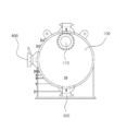
At this time, the pressure vessel for separating the crude oil, as shown in Figure 1, consisting of a
While passing through the
Thereafter, when the crude oil is continuously injected, the
In addition, the
However, since the structure of the pressure vessel for separating crude oil is a structure in which the crude oil is simply stagnated through the
The present invention was created in view of the above-mentioned problems in the prior art as described above, and induces heat exchange by installing a tube through which a heat medium can flow in a pressure vessel in which crude oil resides, thereby inducing an oil component and Its main purpose is to provide a crude oil separation pressure vessel that can reduce the residence time and reduce the size of the pressure vessel by rapidly expanding the separation efficiency of water, thereby reducing the cost and increasing the treatment efficiency.
The present invention is a means for achieving the above object, an elliptical container body, a crude oil inlet piped through the one side surface of the container body, the baffle formed to protrude a predetermined height from the inner bottom surface of the container body to partition the inside of the container body , An oil outlet for storing oil components overflowing the baffle, an oil outlet formed on the bottom surface of the oil storage space, a gas outlet formed on the ceiling surface of the oil storage space, and water formed on one lower surface of the space partitioned by the baffle and storing crude oil In the pressure vessel for crude oil separation comprising; The crude oil storage space partitioned by the baffle provides a pressure separation vessel for improving the separation efficiency, characterized in that the heating pipe for heating the crude oil is further installed through the container body is drawn through and drawn out through the container body. .
In this case, the heating tube is characterized in that the pipe is piped in any one of a zigzag shape, U-shape, lattice shape on the crude oil storage space.
In addition, the heating tube is characterized in that the electric heater or the heat medium is embedded.
In addition, the heating tube is supported by a support, the support is characterized in that the plate is formed in a number of holes perforated to interfere with the flow rate of the crude oil.
According to the present invention, the separation efficiency of the oil component and water contained in the crude oil is improved through heat exchange using the heat medium, and thus the residence time of the crude oil is shortened, so that sufficient treatment can be achieved without increasing the pressure vessel.
1 is an exemplary view of a pressure vessel for separating crude oil according to the prior art.
2 is an exemplary view showing a pressure vessel for separating crude oil having improved separation efficiency according to the present invention.
3 is an exemplary front view of a pressure vessel for separating crude oil having improved separation efficiency according to the present invention.
4 is an exemplary side view of a pressure vessel for separating crude oil having a high separation efficiency according to the present invention.
Hereinafter, preferred embodiments of the present invention will be described in detail with reference to the accompanying drawings.
2 is an exemplary view showing a pressure vessel for separating crude oil with high separation efficiency according to the present invention, Figure 3 is an exemplary front view of a pressure vessel for separating crude oil with high separation efficiency according to the present invention, Figure 4 is in the present invention Accordingly, an exemplary side view of a pressure vessel for separating crude oil has been improved.
As shown in Figure 2, the crude oil separation pressure vessel according to the present invention includes a container body (100).
The
In addition, the one side of the longitudinal direction of the
The
In addition, the other end of the
Therefore, the crude oil supplied through the crude oil supply pipe may be injected into the
In addition, the
The
Accordingly, when crude oil is injected into the
The
That is, both the
In addition, the
Herein, the above-described structure is the same as or similar to the existing structure.
In the present invention, in addition, the
The
Here, the
To this end, the
In addition, the
In the case of an electric heater, a coil-shaped heater wire may be provided in a form embedded in the
In addition, in the case of the electric heater, a means for supplying electricity is provided outside the
In addition, in the case of the heat medium, a heat medium tank, a pump, etc. are provided outside the
In addition, although not shown in detail, the
In addition, in Figure 2, but the
The present invention having such a configuration has the following operational relationship.
Crude oil injected through the
At this time, the crude oil is gradually supplied because it is continuously supplied, and at the same time by heating the
In this process, the oil contained in crude oil rises more quickly, while water is relatively heavy and is directed downward.
Then, when the height of the crude oil exceeds the
In addition, the water stored in the bottom of the crude oil storage space is discharged through the
As such, when the
100: container body 110: crude oil inlet
200: baffle 300: reservoir
310: oil outlet 320: gas outlet
330: water outlet 400: heating tube
410: support
Claims (4)
Crude oil separation pressure vessel, the separation efficiency of the crude oil storage space partitioned by the baffle is characterized in that the heating pipe for supplying heat to the crude oil is piped in the form that is drawn out after passing through the container body.
The heating pipe is a pressure vessel for separation of crude oil with improved separation efficiency, characterized in that the pipe is piped in any one of a zigzag shape, U-shape, lattice shape on the crude oil storage space.
The pressure vessel for separating crude oil with improved separation efficiency, characterized in that the heating tube inside the electric heater or heat medium.
The heating tube is supported by a support, wherein the support is a crude oil separation pressure vessel for separation efficiency, characterized in that the plurality of holes perforated plate shape to hinder the flow rate of crude oil.
Priority Applications (1)
| Application Number | Priority Date | Filing Date | Title |
|---|---|---|---|
| KR1020110059786A KR20120140109A (en) | 2011-06-20 | 2011-06-20 | Pressure vessel for crude oil separation with enhanced separating efficiency |
Applications Claiming Priority (1)
| Application Number | Priority Date | Filing Date | Title |
|---|---|---|---|
| KR1020110059786A KR20120140109A (en) | 2011-06-20 | 2011-06-20 | Pressure vessel for crude oil separation with enhanced separating efficiency |
Publications (1)
| Publication Number | Publication Date |
|---|---|
| KR20120140109A true KR20120140109A (en) | 2012-12-28 |
Family
ID=47906258
Family Applications (1)
| Application Number | Title | Priority Date | Filing Date |
|---|---|---|---|
| KR1020110059786A KR20120140109A (en) | 2011-06-20 | 2011-06-20 | Pressure vessel for crude oil separation with enhanced separating efficiency |
Country Status (1)
| Country | Link |
|---|---|
| KR (1) | KR20120140109A (en) |
Cited By (2)
| Publication number | Priority date | Publication date | Assignee | Title |
|---|---|---|---|---|
| KR20160001282A (en) * | 2014-06-27 | 2016-01-06 | 삼성중공업 주식회사 | Apparatus for recovering MEG |
| KR20170040556A (en) | 2015-10-05 | 2017-04-13 | 대우조선해양 주식회사 | Crude Oil Separation System of Marine Floating Structure |
-
2011
- 2011-06-20 KR KR1020110059786A patent/KR20120140109A/en not_active Application Discontinuation
Cited By (2)
| Publication number | Priority date | Publication date | Assignee | Title |
|---|---|---|---|---|
| KR20160001282A (en) * | 2014-06-27 | 2016-01-06 | 삼성중공업 주식회사 | Apparatus for recovering MEG |
| KR20170040556A (en) | 2015-10-05 | 2017-04-13 | 대우조선해양 주식회사 | Crude Oil Separation System of Marine Floating Structure |
Similar Documents
| Publication | Publication Date | Title |
|---|---|---|
| US9657966B2 (en) | Single bi-temperature thermal storage tank for application in solar thermal plant | |
| EP2320187B1 (en) | Vertical fluid heat exchanger installed within natural thermal energy body | |
| EP3553392B1 (en) | Cooking appliance | |
| JP2010101564A (en) | Steam generator | |
| TWI669412B (en) | Reagent delivery system freeze prevention heat exchanger | |
| KR20120140109A (en) | Pressure vessel for crude oil separation with enhanced separating efficiency | |
| KR20100054148A (en) | Boiler having a section for preheating water | |
| JP2016198757A (en) | Three-phase separator having high thermal efficiency | |
| KR101195436B1 (en) | Hot water boiler | |
| BR112017012523B1 (en) | STEAM GENERATOR WITH A BEAM OF HORIZONTAL HEAT EXCHANGE PIPES AND ITS ASSEMBLY METHOD | |
| CN109690227A (en) | Riser type heat exchanger and heat change method | |
| KR101339668B1 (en) | Condensation-water recovery device | |
| KR20130085663A (en) | Boiler using electricity | |
| KR101109533B1 (en) | Sea Water Desalting Device by Low Pressure Evaporation Improved Evaporation Performance | |
| CN102997430A (en) | Heating and heat storage integrated heat-preserving water tank of heat pump water heater | |
| CN103398600A (en) | Bath water waste heat recoverer | |
| KR101816951B1 (en) | U-tube vaporizer | |
| RU155050U1 (en) | OIL DRAINAGE DEVICE | |
| KR101258059B1 (en) | Boiler system | |
| JP5356105B2 (en) | Heater | |
| KR20100006985U (en) | Device of recollecting wasted heat for boiler | |
| ES2275991T3 (en) | SPECIAL HEATING INSTALLATION WITH A REGULATOR ACCUMULATOR OR A COMPOSITE ACCUMULATION BOILER. | |
| CN103471234A (en) | Electromagnetic water storage type water heater | |
| KR20120068437A (en) | Fuel tank for ships | |
| CN203595262U (en) | Electromagnetic water storage type water heater |
Legal Events
| Date | Code | Title | Description |
|---|---|---|---|
| WITN | Withdrawal due to no request for examination |