KR20120138762A - Medical device lock mechanism - Google Patents
Medical device lock mechanism Download PDFInfo
- Publication number
- KR20120138762A KR20120138762A KR20127023817A KR20127023817A KR20120138762A KR 20120138762 A KR20120138762 A KR 20120138762A KR 20127023817 A KR20127023817 A KR 20127023817A KR 20127023817 A KR20127023817 A KR 20127023817A KR 20120138762 A KR20120138762 A KR 20120138762A
- Authority
- KR
- South Korea
- Prior art keywords
- implant body
- segments
- locking element
- locking
- implant
- Prior art date
Links
Images


Classifications
-
- A—HUMAN NECESSITIES
- A61—MEDICAL OR VETERINARY SCIENCE; HYGIENE
- A61F—FILTERS IMPLANTABLE INTO BLOOD VESSELS; PROSTHESES; DEVICES PROVIDING PATENCY TO, OR PREVENTING COLLAPSING OF, TUBULAR STRUCTURES OF THE BODY, e.g. STENTS; ORTHOPAEDIC, NURSING OR CONTRACEPTIVE DEVICES; FOMENTATION; TREATMENT OR PROTECTION OF EYES OR EARS; BANDAGES, DRESSINGS OR ABSORBENT PADS; FIRST-AID KITS
- A61F2/00—Filters implantable into blood vessels; Prostheses, i.e. artificial substitutes or replacements for parts of the body; Appliances for connecting them with the body; Devices providing patency to, or preventing collapsing of, tubular structures of the body, e.g. stents
- A61F2/02—Prostheses implantable into the body
- A61F2/30—Joints
- A61F2/44—Joints for the spine, e.g. vertebrae, spinal discs
-
- A—HUMAN NECESSITIES
- A61—MEDICAL OR VETERINARY SCIENCE; HYGIENE
- A61B—DIAGNOSIS; SURGERY; IDENTIFICATION
- A61B17/00—Surgical instruments, devices or methods, e.g. tourniquets
- A61B17/56—Surgical instruments or methods for treatment of bones or joints; Devices specially adapted therefor
- A61B17/58—Surgical instruments or methods for treatment of bones or joints; Devices specially adapted therefor for osteosynthesis, e.g. bone plates, screws, setting implements or the like
- A61B17/68—Internal fixation devices, including fasteners and spinal fixators, even if a part thereof projects from the skin
- A61B17/70—Spinal positioners or stabilisers ; Bone stabilisers comprising fluid filler in an implant
-
- A—HUMAN NECESSITIES
- A61—MEDICAL OR VETERINARY SCIENCE; HYGIENE
- A61F—FILTERS IMPLANTABLE INTO BLOOD VESSELS; PROSTHESES; DEVICES PROVIDING PATENCY TO, OR PREVENTING COLLAPSING OF, TUBULAR STRUCTURES OF THE BODY, e.g. STENTS; ORTHOPAEDIC, NURSING OR CONTRACEPTIVE DEVICES; FOMENTATION; TREATMENT OR PROTECTION OF EYES OR EARS; BANDAGES, DRESSINGS OR ABSORBENT PADS; FIRST-AID KITS
- A61F2/00—Filters implantable into blood vessels; Prostheses, i.e. artificial substitutes or replacements for parts of the body; Appliances for connecting them with the body; Devices providing patency to, or preventing collapsing of, tubular structures of the body, e.g. stents
- A61F2/02—Prostheses implantable into the body
- A61F2/28—Bones
-
- A—HUMAN NECESSITIES
- A61—MEDICAL OR VETERINARY SCIENCE; HYGIENE
- A61F—FILTERS IMPLANTABLE INTO BLOOD VESSELS; PROSTHESES; DEVICES PROVIDING PATENCY TO, OR PREVENTING COLLAPSING OF, TUBULAR STRUCTURES OF THE BODY, e.g. STENTS; ORTHOPAEDIC, NURSING OR CONTRACEPTIVE DEVICES; FOMENTATION; TREATMENT OR PROTECTION OF EYES OR EARS; BANDAGES, DRESSINGS OR ABSORBENT PADS; FIRST-AID KITS
- A61F2/00—Filters implantable into blood vessels; Prostheses, i.e. artificial substitutes or replacements for parts of the body; Appliances for connecting them with the body; Devices providing patency to, or preventing collapsing of, tubular structures of the body, e.g. stents
- A61F2/02—Prostheses implantable into the body
- A61F2/30—Joints
- A61F2/44—Joints for the spine, e.g. vertebrae, spinal discs
- A61F2/4455—Joints for the spine, e.g. vertebrae, spinal discs for the fusion of spinal bodies, e.g. intervertebral fusion of adjacent spinal bodies, e.g. fusion cages
-
- A—HUMAN NECESSITIES
- A61—MEDICAL OR VETERINARY SCIENCE; HYGIENE
- A61B—DIAGNOSIS; SURGERY; IDENTIFICATION
- A61B17/00—Surgical instruments, devices or methods, e.g. tourniquets
- A61B17/56—Surgical instruments or methods for treatment of bones or joints; Devices specially adapted therefor
- A61B17/58—Surgical instruments or methods for treatment of bones or joints; Devices specially adapted therefor for osteosynthesis, e.g. bone plates, screws, setting implements or the like
- A61B17/68—Internal fixation devices, including fasteners and spinal fixators, even if a part thereof projects from the skin
- A61B17/70—Spinal positioners or stabilisers ; Bone stabilisers comprising fluid filler in an implant
- A61B17/7094—Solid vertebral fillers; devices for inserting such fillers
-
- A—HUMAN NECESSITIES
- A61—MEDICAL OR VETERINARY SCIENCE; HYGIENE
- A61B—DIAGNOSIS; SURGERY; IDENTIFICATION
- A61B17/00—Surgical instruments, devices or methods, e.g. tourniquets
- A61B17/56—Surgical instruments or methods for treatment of bones or joints; Devices specially adapted therefor
- A61B17/58—Surgical instruments or methods for treatment of bones or joints; Devices specially adapted therefor for osteosynthesis, e.g. bone plates, screws, setting implements or the like
- A61B17/88—Osteosynthesis instruments; Methods or means for implanting or extracting internal or external fixation devices
- A61B17/885—Tools for expanding or compacting bones or discs or cavities therein
- A61B17/8852—Tools for expanding or compacting bones or discs or cavities therein capable of being assembled or enlarged, or changing shape, inside the bone or disc
-
- A—HUMAN NECESSITIES
- A61—MEDICAL OR VETERINARY SCIENCE; HYGIENE
- A61F—FILTERS IMPLANTABLE INTO BLOOD VESSELS; PROSTHESES; DEVICES PROVIDING PATENCY TO, OR PREVENTING COLLAPSING OF, TUBULAR STRUCTURES OF THE BODY, e.g. STENTS; ORTHOPAEDIC, NURSING OR CONTRACEPTIVE DEVICES; FOMENTATION; TREATMENT OR PROTECTION OF EYES OR EARS; BANDAGES, DRESSINGS OR ABSORBENT PADS; FIRST-AID KITS
- A61F2/00—Filters implantable into blood vessels; Prostheses, i.e. artificial substitutes or replacements for parts of the body; Appliances for connecting them with the body; Devices providing patency to, or preventing collapsing of, tubular structures of the body, e.g. stents
- A61F2/02—Prostheses implantable into the body
- A61F2/28—Bones
- A61F2002/2835—Bone graft implants for filling a bony defect or an endoprosthesis cavity, e.g. by synthetic material or biological material
-
- A—HUMAN NECESSITIES
- A61—MEDICAL OR VETERINARY SCIENCE; HYGIENE
- A61F—FILTERS IMPLANTABLE INTO BLOOD VESSELS; PROSTHESES; DEVICES PROVIDING PATENCY TO, OR PREVENTING COLLAPSING OF, TUBULAR STRUCTURES OF THE BODY, e.g. STENTS; ORTHOPAEDIC, NURSING OR CONTRACEPTIVE DEVICES; FOMENTATION; TREATMENT OR PROTECTION OF EYES OR EARS; BANDAGES, DRESSINGS OR ABSORBENT PADS; FIRST-AID KITS
- A61F2/00—Filters implantable into blood vessels; Prostheses, i.e. artificial substitutes or replacements for parts of the body; Appliances for connecting them with the body; Devices providing patency to, or preventing collapsing of, tubular structures of the body, e.g. stents
- A61F2/02—Prostheses implantable into the body
- A61F2/30—Joints
- A61F2002/30001—Additional features of subject-matter classified in A61F2/28, A61F2/30 and subgroups thereof
- A61F2002/30316—The prosthesis having different structural features at different locations within the same prosthesis; Connections between prosthetic parts; Special structural features of bone or joint prostheses not otherwise provided for
- A61F2002/30329—Connections or couplings between prosthetic parts, e.g. between modular parts; Connecting elements
- A61F2002/30331—Connections or couplings between prosthetic parts, e.g. between modular parts; Connecting elements made by longitudinally pushing a protrusion into a complementarily-shaped recess, e.g. held by friction fit
- A61F2002/30362—Connections or couplings between prosthetic parts, e.g. between modular parts; Connecting elements made by longitudinally pushing a protrusion into a complementarily-shaped recess, e.g. held by friction fit with possibility of relative movement between the protrusion and the recess
- A61F2002/30364—Rotation about the common longitudinal axis
- A61F2002/30367—Rotation about the common longitudinal axis with additional means for preventing said rotation
-
- A—HUMAN NECESSITIES
- A61—MEDICAL OR VETERINARY SCIENCE; HYGIENE
- A61F—FILTERS IMPLANTABLE INTO BLOOD VESSELS; PROSTHESES; DEVICES PROVIDING PATENCY TO, OR PREVENTING COLLAPSING OF, TUBULAR STRUCTURES OF THE BODY, e.g. STENTS; ORTHOPAEDIC, NURSING OR CONTRACEPTIVE DEVICES; FOMENTATION; TREATMENT OR PROTECTION OF EYES OR EARS; BANDAGES, DRESSINGS OR ABSORBENT PADS; FIRST-AID KITS
- A61F2/00—Filters implantable into blood vessels; Prostheses, i.e. artificial substitutes or replacements for parts of the body; Appliances for connecting them with the body; Devices providing patency to, or preventing collapsing of, tubular structures of the body, e.g. stents
- A61F2/02—Prostheses implantable into the body
- A61F2/30—Joints
- A61F2002/30001—Additional features of subject-matter classified in A61F2/28, A61F2/30 and subgroups thereof
- A61F2002/30316—The prosthesis having different structural features at different locations within the same prosthesis; Connections between prosthetic parts; Special structural features of bone or joint prostheses not otherwise provided for
- A61F2002/30329—Connections or couplings between prosthetic parts, e.g. between modular parts; Connecting elements
- A61F2002/30462—Connections or couplings between prosthetic parts, e.g. between modular parts; Connecting elements retained or tied with a rope, string, thread, wire or cable
-
- A—HUMAN NECESSITIES
- A61—MEDICAL OR VETERINARY SCIENCE; HYGIENE
- A61F—FILTERS IMPLANTABLE INTO BLOOD VESSELS; PROSTHESES; DEVICES PROVIDING PATENCY TO, OR PREVENTING COLLAPSING OF, TUBULAR STRUCTURES OF THE BODY, e.g. STENTS; ORTHOPAEDIC, NURSING OR CONTRACEPTIVE DEVICES; FOMENTATION; TREATMENT OR PROTECTION OF EYES OR EARS; BANDAGES, DRESSINGS OR ABSORBENT PADS; FIRST-AID KITS
- A61F2/00—Filters implantable into blood vessels; Prostheses, i.e. artificial substitutes or replacements for parts of the body; Appliances for connecting them with the body; Devices providing patency to, or preventing collapsing of, tubular structures of the body, e.g. stents
- A61F2/02—Prostheses implantable into the body
- A61F2/30—Joints
- A61F2002/30001—Additional features of subject-matter classified in A61F2/28, A61F2/30 and subgroups thereof
- A61F2002/30316—The prosthesis having different structural features at different locations within the same prosthesis; Connections between prosthetic parts; Special structural features of bone or joint prostheses not otherwise provided for
- A61F2002/30329—Connections or couplings between prosthetic parts, e.g. between modular parts; Connecting elements
- A61F2002/30469—Connections or couplings between prosthetic parts, e.g. between modular parts; Connecting elements using band clamps
-
- A—HUMAN NECESSITIES
- A61—MEDICAL OR VETERINARY SCIENCE; HYGIENE
- A61F—FILTERS IMPLANTABLE INTO BLOOD VESSELS; PROSTHESES; DEVICES PROVIDING PATENCY TO, OR PREVENTING COLLAPSING OF, TUBULAR STRUCTURES OF THE BODY, e.g. STENTS; ORTHOPAEDIC, NURSING OR CONTRACEPTIVE DEVICES; FOMENTATION; TREATMENT OR PROTECTION OF EYES OR EARS; BANDAGES, DRESSINGS OR ABSORBENT PADS; FIRST-AID KITS
- A61F2/00—Filters implantable into blood vessels; Prostheses, i.e. artificial substitutes or replacements for parts of the body; Appliances for connecting them with the body; Devices providing patency to, or preventing collapsing of, tubular structures of the body, e.g. stents
- A61F2/02—Prostheses implantable into the body
- A61F2/30—Joints
- A61F2002/30001—Additional features of subject-matter classified in A61F2/28, A61F2/30 and subgroups thereof
- A61F2002/30316—The prosthesis having different structural features at different locations within the same prosthesis; Connections between prosthetic parts; Special structural features of bone or joint prostheses not otherwise provided for
- A61F2002/30329—Connections or couplings between prosthetic parts, e.g. between modular parts; Connecting elements
- A61F2002/30518—Connections or couplings between prosthetic parts, e.g. between modular parts; Connecting elements with possibility of relative movement between the prosthetic parts
- A61F2002/3052—Connections or couplings between prosthetic parts, e.g. between modular parts; Connecting elements with possibility of relative movement between the prosthetic parts unrestrained in only one direction, e.g. moving unidirectionally
- A61F2002/30522—Connections or couplings between prosthetic parts, e.g. between modular parts; Connecting elements with possibility of relative movement between the prosthetic parts unrestrained in only one direction, e.g. moving unidirectionally releasable, e.g. using a releasable ratchet
-
- A—HUMAN NECESSITIES
- A61—MEDICAL OR VETERINARY SCIENCE; HYGIENE
- A61F—FILTERS IMPLANTABLE INTO BLOOD VESSELS; PROSTHESES; DEVICES PROVIDING PATENCY TO, OR PREVENTING COLLAPSING OF, TUBULAR STRUCTURES OF THE BODY, e.g. STENTS; ORTHOPAEDIC, NURSING OR CONTRACEPTIVE DEVICES; FOMENTATION; TREATMENT OR PROTECTION OF EYES OR EARS; BANDAGES, DRESSINGS OR ABSORBENT PADS; FIRST-AID KITS
- A61F2/00—Filters implantable into blood vessels; Prostheses, i.e. artificial substitutes or replacements for parts of the body; Appliances for connecting them with the body; Devices providing patency to, or preventing collapsing of, tubular structures of the body, e.g. stents
- A61F2/02—Prostheses implantable into the body
- A61F2/30—Joints
- A61F2002/30001—Additional features of subject-matter classified in A61F2/28, A61F2/30 and subgroups thereof
- A61F2002/30621—Features concerning the anatomical functioning or articulation of the prosthetic joint
- A61F2002/30624—Hinged joint, e.g. with transverse axle restricting the movement
- A61F2002/30632—Hinged joint, e.g. with transverse axle restricting the movement with rotation-limiting stops, e.g. projections or recesses
-
- A—HUMAN NECESSITIES
- A61—MEDICAL OR VETERINARY SCIENCE; HYGIENE
- A61F—FILTERS IMPLANTABLE INTO BLOOD VESSELS; PROSTHESES; DEVICES PROVIDING PATENCY TO, OR PREVENTING COLLAPSING OF, TUBULAR STRUCTURES OF THE BODY, e.g. STENTS; ORTHOPAEDIC, NURSING OR CONTRACEPTIVE DEVICES; FOMENTATION; TREATMENT OR PROTECTION OF EYES OR EARS; BANDAGES, DRESSINGS OR ABSORBENT PADS; FIRST-AID KITS
- A61F2/00—Filters implantable into blood vessels; Prostheses, i.e. artificial substitutes or replacements for parts of the body; Appliances for connecting them with the body; Devices providing patency to, or preventing collapsing of, tubular structures of the body, e.g. stents
- A61F2/02—Prostheses implantable into the body
- A61F2/30—Joints
- A61F2/44—Joints for the spine, e.g. vertebrae, spinal discs
- A61F2002/4415—Joints for the spine, e.g. vertebrae, spinal discs elements of the prosthesis being arranged in a chain like manner
-
- A—HUMAN NECESSITIES
- A61—MEDICAL OR VETERINARY SCIENCE; HYGIENE
- A61F—FILTERS IMPLANTABLE INTO BLOOD VESSELS; PROSTHESES; DEVICES PROVIDING PATENCY TO, OR PREVENTING COLLAPSING OF, TUBULAR STRUCTURES OF THE BODY, e.g. STENTS; ORTHOPAEDIC, NURSING OR CONTRACEPTIVE DEVICES; FOMENTATION; TREATMENT OR PROTECTION OF EYES OR EARS; BANDAGES, DRESSINGS OR ABSORBENT PADS; FIRST-AID KITS
- A61F2/00—Filters implantable into blood vessels; Prostheses, i.e. artificial substitutes or replacements for parts of the body; Appliances for connecting them with the body; Devices providing patency to, or preventing collapsing of, tubular structures of the body, e.g. stents
- A61F2/02—Prostheses implantable into the body
- A61F2/30—Joints
- A61F2/44—Joints for the spine, e.g. vertebrae, spinal discs
- A61F2002/448—Joints for the spine, e.g. vertebrae, spinal discs comprising multiple adjacent spinal implants within the same intervertebral space or within the same vertebra, e.g. comprising two adjacent spinal implants
-
- A—HUMAN NECESSITIES
- A61—MEDICAL OR VETERINARY SCIENCE; HYGIENE
- A61F—FILTERS IMPLANTABLE INTO BLOOD VESSELS; PROSTHESES; DEVICES PROVIDING PATENCY TO, OR PREVENTING COLLAPSING OF, TUBULAR STRUCTURES OF THE BODY, e.g. STENTS; ORTHOPAEDIC, NURSING OR CONTRACEPTIVE DEVICES; FOMENTATION; TREATMENT OR PROTECTION OF EYES OR EARS; BANDAGES, DRESSINGS OR ABSORBENT PADS; FIRST-AID KITS
- A61F2/00—Filters implantable into blood vessels; Prostheses, i.e. artificial substitutes or replacements for parts of the body; Appliances for connecting them with the body; Devices providing patency to, or preventing collapsing of, tubular structures of the body, e.g. stents
- A61F2/02—Prostheses implantable into the body
- A61F2/30—Joints
- A61F2/46—Special tools or methods for implanting or extracting artificial joints, accessories, bone grafts or substitutes, or particular adaptations therefor
- A61F2002/4635—Special tools or methods for implanting or extracting artificial joints, accessories, bone grafts or substitutes, or particular adaptations therefor using minimally invasive surgery
-
- A—HUMAN NECESSITIES
- A61—MEDICAL OR VETERINARY SCIENCE; HYGIENE
- A61F—FILTERS IMPLANTABLE INTO BLOOD VESSELS; PROSTHESES; DEVICES PROVIDING PATENCY TO, OR PREVENTING COLLAPSING OF, TUBULAR STRUCTURES OF THE BODY, e.g. STENTS; ORTHOPAEDIC, NURSING OR CONTRACEPTIVE DEVICES; FOMENTATION; TREATMENT OR PROTECTION OF EYES OR EARS; BANDAGES, DRESSINGS OR ABSORBENT PADS; FIRST-AID KITS
- A61F2220/00—Fixations or connections for prostheses classified in groups A61F2/00 - A61F2/26 or A61F2/82 or A61F9/00 or A61F11/00 or subgroups thereof
- A61F2220/0025—Connections or couplings between prosthetic parts, e.g. between modular parts; Connecting elements
- A61F2220/0033—Connections or couplings between prosthetic parts, e.g. between modular parts; Connecting elements made by longitudinally pushing a protrusion into a complementary-shaped recess, e.g. held by friction fit
-
- A—HUMAN NECESSITIES
- A61—MEDICAL OR VETERINARY SCIENCE; HYGIENE
- A61F—FILTERS IMPLANTABLE INTO BLOOD VESSELS; PROSTHESES; DEVICES PROVIDING PATENCY TO, OR PREVENTING COLLAPSING OF, TUBULAR STRUCTURES OF THE BODY, e.g. STENTS; ORTHOPAEDIC, NURSING OR CONTRACEPTIVE DEVICES; FOMENTATION; TREATMENT OR PROTECTION OF EYES OR EARS; BANDAGES, DRESSINGS OR ABSORBENT PADS; FIRST-AID KITS
- A61F2220/00—Fixations or connections for prostheses classified in groups A61F2/00 - A61F2/26 or A61F2/82 or A61F9/00 or A61F11/00 or subgroups thereof
- A61F2220/0025—Connections or couplings between prosthetic parts, e.g. between modular parts; Connecting elements
- A61F2220/0075—Connections or couplings between prosthetic parts, e.g. between modular parts; Connecting elements sutured, ligatured or stitched, retained or tied with a rope, string, thread, wire or cable
Abstract
의료 디바이스(medical device)(10)는, 도입(delivery)을 위한 펼쳐진 상태와, 굽혀진 또는 대체로 곡이 진 배치 상태(deployed state)를 취하게끔 힌지식으로 서로 연결된 다수의 세그먼트(segment)(30)들을 지닌 임플란트 몸체(implant body)(20)를 포함한다. 임플란트 몸체는 적어도 2개의 다른 세그먼트들에, 예컨대 다수의 세그먼트들에 결합 엘리먼트들(engagement elements)을 가질 수 있다. 임플란트 몸체의 원위측(distal) 세그먼트에 고정된 기다란 로킹 엘리먼트(elongated locking element)는 적어도 각 결합 엘리먼트에 대한 돌기부들(projections)을 가질 수 있다. 로킹 엘리먼트에 인장력이 가해지면, 임플란트 몸체는 펼쳐진 상태에서 굽힘 배치 상태(flexed deployed state)로 변하게 된다. 로킹 엘리먼트가 곡이 진 배치 상태에 도달하게끔 변형되면, 임플란트 몸체의 결합 엘리먼트들이 로킹 엘리먼트의 돌기부들과 매칭(matching)됨으로써, 임플란트 몸체의 굽혀진 세그먼트들은 로킹이 된다. 임플란트가 배치된 후에는 개방이 되지 않게끔 매우 확고한 로킹이 이루어질 수 있다. The medical device 10 includes a plurality of segments 30 connected to one another hingedly to take an expanded state for delivery and a bent or generally deployed state. Implant body 20 with The implant body may have engagement elements in at least two different segments, eg in multiple segments. The elongated locking element secured to the distal segment of the implant body may have projections for at least each engagement element. When tensioning force is applied to the locking element, the implant body changes from the deployed state to the flexed deployed state. When the locking element is deformed to reach a curved placement state, the mating elements of the implant body match the protrusions of the locking element such that the bent segments of the implant body become locked. After the implant is placed, very firm locking can be achieved to prevent it from opening.
Description
본 발명은, 출원인 시갈(Siegal)이 2010년 2월 16일자로 출원한 미국 특허 가출원번호 제61/304,857를 기초로 우선권을 주장하는 바이다. The present invention claims priority based on US Patent Provisional Application No. 61 / 304,857, filed on February 16, 2010, by Applicant Siegal.
본 발명은 척추 수술용과 같은 임플란트 몸체들(implant bodies)에 관한 것이며, 더욱 상세하게는, 일단 임플란트 몸체가 신체 내에 이식되면 임플란트 몸체가 개방되는 것을 방지하기 위한 매우 안정된 로킹 장치(locking arrangement)를 가지는 임플란트 디바이스(device)에 관한 것이다.
The present invention relates to implant bodies, such as for spinal surgery, and more particularly, having a very stable locking arrangement to prevent the implant body from opening once the implant body is implanted into the body. The present invention relates to an implant device.
임플란트 및 이를 신체의 척추 또는 다른 부위 내부에 배치하기 위한 다양한 디바이스들이 제안되어 왔다. 임플란트에 있어서 중요한 점은, 임플란트가 효과적으로 도입되어야 할 뿐만 아니라, 임플란트가 신체 내에 배치된 후에는 임플란트가 제 위치를 유지해야하며 개방되지 않아야 한다는 점이다. 임플란트에 대한 확실하고 믿음직한 배치 및 안정성은 매우 중요하다. 만일 임플란트가 배치된 후에 개방되면 이는 주위의 조직들에 손상을 주고, 척추 수술의 효과를 망치게 될 것이다. Various devices have been proposed for implants and their placement inside the spine or other parts of the body. Important for the implant is that not only the implant must be introduced effectively, but also that the implant must remain in place and not open after the implant is placed in the body. Reliable and reliable placement and stability of the implant is very important. If the implant is opened after placement, it will damage the surrounding tissues and spoil the effect of spinal surgery.
2009년 2월 12일 공개된, 본 출원인의 PCT 특허출원공보 WO 2009/019669호에는, 펼쳐진 형태에서 신체 내로 인입되고 그 다음 신체 내에서 대략 굴곡진 형태를 취하게 되는 기다란 조임 엘리먼트(elongated tightening element) 및 임플란트 몸체(implant body)를 포함하는 임플란트가 교시되어 있다. 상기 공보 내용은 참조에 의해 전체적으로 본 명세서에 통합된다. Applicant's PCT Patent Application Publication No. WO 2009/019669, published February 12, 2009, describes an elongated tightening element that is introduced into the body in its unfolded form and then takes a roughly curved form within the body. And implants, including implant bodies. The contents of this publication are incorporated herein by reference in their entirety.
따라서, 예컨대 척추 수술에 있어서 신체 내에 임플란트가 배치된 후에 개방되지 않는 임플란트 (그리고 관련된 방법)을 제공하는 것이 매우 유익할 것이다.
Thus, it would be very beneficial to provide an implant (and associated method) that does not open after the implant is placed in the body, for example in spinal surgery.
본 발명의 일 양상에 따르면 의료 디바이스가 제공되는데, 이 의료 디바이스는, (a) 펼쳐진 상태(straightened state) 및 굽힘 배치 상태(flexed deployed state)의 양상을 취하게끔 상호연결된 다수의 세그먼트들(a plurality of segments)을 포함하는 임플란트 몸체(implant body)로서, 상기 임플란트 몸체는 적어도 2개의 결합 엘리먼트(engagement element)들을 지니고 형성되어 있으며, 적어도 2개의 다른 세그먼트들 각각은 결합 엘리먼트를 가지는, 임플란트 몸체; 및 (b) 적어도 2개의 결합 엘리먼트들에 대응하는 적어도 2개의 돌기부(projection)들을 가지며, 상기 임플란트 몸체의 한 세그먼트에 고정되는 기다란 로킹 엘리먼트(elongated locking element);를 포함하며, 상기 임플란트 몸체 및 상기 로킹 엘리먼트는, 상기 로킹 엘리먼트가 상기 굽힘 배치 상태에 도달하게끔 변형될 때, 로킹 엘리먼트의 적어도 2개의 돌기부들이 임플란트 몸체의 적어도 2개의 결합 엘리먼트들과 결합하여 로킹되도록 형성되어 있으며, 연속된 세그먼트들이 굽혀지고 로킹된 뒤에 각 로킹 세그먼트(locking segment)는 로킹된 상태로 유지되며, 상기 로킹 장치(locking arrangement)는 상기 로킹 엘리먼트를 상기 임플란트 몸체에 대해 로킹하는 데 효과적이여서, 상기 임플란트를 상기 굽힘 배치 상태로 유지하는 것을 특징으로 한다. According to one aspect of the present invention there is provided a medical device comprising: (a) a plurality of segments interconnected to take an aspect of a straightened state and a flexed deployed state; an implant body comprising an implant body, the implant body having at least two engagement elements, each of the at least two other segments having an engagement element; And (b) an elongated locking element having at least two projections corresponding to at least two engagement elements, the elongated locking element being secured to one segment of the implant body. The locking element is formed such that when the locking element is deformed to reach the bending arrangement, at least two protrusions of the locking element engage and lock with at least two engagement elements of the implant body, the successive segments being bent After locking and locking, each locking segment remains locked and the locking arrangement is effective to lock the locking element against the implant body, thereby bringing the implant into the bending arrangement. It is characterized by maintaining.
본 발명의 다른 양상에 따른 의료 디비이스는, (a) 펼쳐진 상태 및 굽힘 배치 상태의 양상을 취하게끔 상호연결된 다수의 세그먼트들을 포함하는 임플란트 몸체로서, 상기 임플란트 몸체는 적어도 2개의 소켓(socket)들을 가지며, 적어도 2개의 다른 세그먼트들 각각은 소켓을 가지는, 임플란트 몸체; 및 (b) 상기 적어도 2개의 소켓들에 대응하는 적어도 2개의 벌지(bulge)들을 가지며, 상기 임플란트 몸체의 한 세그먼트에 고정되는 기다란 로킹 엘리먼트;를 포함하며, 상기 임플란트 몸체 및 상기 로킹 엘리먼트는, 상기 로킹 엘리먼트가 상기 굽힘 배치 상태에 도달하게끔 변형될 때, 로킹 엘리먼트의 적어도 2개의 벌지들이 상기 임플란트 몸체의 적어도 2개의 소켓들과 결합하여 로킹되도록 형성되어 있으며, 상기 로킹 장치는, 다수의 세그먼트들에서 상기 로킹 엘리먼트를 상기 임플란트 몸체에 대해 로킹하는 데 효과적이여서, 상기 임플란트를 상기 굽힘 배치 상태로 유지하는 것을 특징으로 한다.A medical device according to another aspect of the invention is an implant body comprising (a) a plurality of segments interconnected to take an aspect of an unfolded and bent arrangement, the implant body having at least two sockets; An implant body, wherein each of the at least two other segments has a socket; And (b) an elongate locking element having at least two bulges corresponding to the at least two sockets, the elongate locking element being secured to one segment of the implant body. When the locking element is deformed to reach the bending arrangement, at least two bulges of the locking element are configured to lock in engagement with at least two sockets of the implant body, the locking device being in a plurality of segments. It is effective to lock the locking element against the implant body, thereby maintaining the implant in the bent arrangement.
본 발명의 또 다른 양상은, 대상자의 신체 내에 의료 디바이스를 배치하는 방법인데, 이 방법은, (a) 펼쳐진 상태의 양상을 취하게끔 상호연결되고 굽힘 배치 상태의 양상을 취하게끔 변형가능한 다수의 세그먼트들을 포함하는 임플란트 몸체로서, 상기 다수의 세그먼트들은 각각 결합 엘리먼트를 가지는, 임플란트 몸체를 제공하는 단계; (b) 적어도 2개의 다른 세그먼트들 중 하나에 고정되고, 상기 임플란트 몸체의 연장방향으로 상기 임플란트 몸체를 따라 연장되며, 결합 엘리먼트들 각각에 대응하는 돌기부들을 가지는 로킹 엘리먼트를 제공하는 단계; 및 (c) 상기 임플란트 몸체를 대상이 되는 신체 내에 전진시키고, 상기 임플란트 몸체가 상기 굽힘 배치 상태로 변형되도록 상기 로킹 엘리먼트에 후방으로의 인장력(rearward tention)을 가하는 단계;를 포함하며, 상기 돌기부들은, 해당하는 세그먼트들을 상기 굽힘 배치 상태에 로킹하기 위해, 대응되는 상기 결합 엘리먼트들과 짝을 이루는 것을 특징으로 한다. Another aspect of the invention is a method of placing a medical device in a subject's body, the method comprising: (a) a plurality of segments that are interconnected and deformable to take an aspect of an unfolded state; An implant body comprising: providing an implant body, wherein the plurality of segments each have a coupling element; (b) providing a locking element secured to one of the at least two different segments, extending along the implant body in the direction of extension of the implant body, the locking element having protrusions corresponding to each of the coupling elements; And (c) advancing the implant body into a target body and applying a rearward tention to the locking element such that the implant body is deformed into the bending arrangement. And mating with corresponding mating elements for locking corresponding segments in the bending arrangement.
다음의 도면, 상세 설명 및 청구항들을 참조하면, 본 발명에 대한 이러한 특징들 및 여타 특징들, 양상들, 장점들이 보다 잘 이해될 것이다.
With reference to the following figures, detailed description and claims, these and other features, aspects, advantages of the present invention will be better understood.
첨부된 도면을 참조로 하여 본 발명에 대한 설명이 기술되는데, 이는 단지 예시적으로 기술된 것이다.
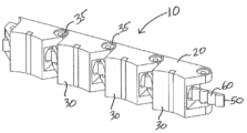
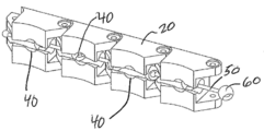
도 1은 본 발명의 일 실시 예에 따라, 임플란트 몸체에 결합된 조임 엘리먼트(tightening element)를 지닌 임플란트 몸체를 포함하는 임플란트에 대한 사시도이다.
도 2는 본 발명의 일 실시 예에 따라, 조임 엘리먼트가 임플란트 몸체의 돌기부들에 결합된 것을 보여주기 위해 해체된 도 1의 부분도이다.
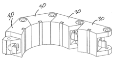
도 3은 본 발명의 일 실시 예에 따라, 한 세그먼트만 제외한 모든 세그먼트들이 굽힘 배치 상태에 있는 도 1의 임플란트에 대한 사시도이다.
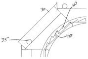
도 4는 본 발명의 일 실시 예에 따라, 조임 엘리먼트가 임플란트 몸체의 돌기부들에 결합된 것을 보여주기 위해 해체된 도 3의 굽혀진 임플란트에 대한 부분 측면도이다.
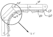
도 5는 도 4에서 원으로 표시된 부분에 대한 확대도로서 임플란트의 로킹 장치(locking arrangement)를 보여주는 도면이다.
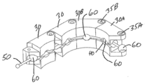
도 6은 본 발명의 다른 실시 예에 따라, 임플란트 몸체 및 임플란트 몸체에 결합된 조임 엘리먼트를 포함하는 임플란트가 펼쳐진 상태에 있는 것을 보여주는 사시도이다.
도 7은 본 발명의 일 실시 예에 따라, 도 6의 임플란트가 굽힘 배치 상태에 있는 것을 보여주는 사시도이다.
도 8은 본 발명의 일 실시 예에 따라, 도 7의 임플란트에서 조임 엘리먼트의 벌지들(bulges)이 임플란트 몸체의 소켓들에 결합된 것을 보여주기 위해 해체된 도 7의 부분도이다.
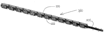
도 9는 본 발명의 또 다른 실시 예에 따라, 임플란트 몸체에 결합된 조임 엘리먼트에 대한 사시도이다.
도 10은 도 9의 조임 엘리먼트에 대한 측면도이다.
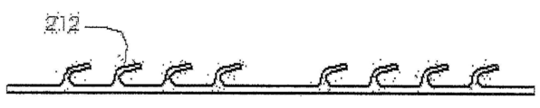
도 11은 본 발명의 실시 예에 따라, 도 9 및 도 10의 임플란트가 펼쳐진 상태에서의 로킹 메카니즘의 두 세그먼트들에 대한 단면도이다.
도 12는 본 발명의 일 실시 예에 따라, 도 9 및 도 10의 임플란트가 굽힘 배치 상태에서의 로킹 메카니즘의 두 세그먼트들에 대한 단면도이다.
도 13은 본 발명의 방법을 보여주는 플로우챠트(flow chart)이다.DESCRIPTION OF THE PREFERRED EMBODIMENTS The description of the present invention is described with reference to the accompanying drawings, which are merely illustrative.
1 is a perspective view of an implant including an implant body having a tightening element coupled to the implant body in accordance with one embodiment of the present invention.
2 is a partial view of FIG. 1 disassembled to show that the tightening element is coupled to the protrusions of the implant body, in accordance with an embodiment of the present invention.
3 is a perspective view of the implant of FIG. 1 in which all segments except one segment are in a bent configuration, in accordance with one embodiment of the present invention.
4 is a partial side view of the bent implant of FIG. 3 disassembled to show that the tightening element is coupled to the protrusions of the implant body, in accordance with one embodiment of the present invention.
FIG. 5 is an enlarged view of the portion indicated by the circle in FIG. 4 showing a locking arrangement of the implant. FIG.
FIG. 6 is a perspective view illustrating an implant in an unfolded state including an implant body and a tightening element coupled to the implant body according to another embodiment of the present disclosure.
FIG. 7 is a perspective view illustrating that the implant of FIG. 6 is in a bending arrangement state, according to an embodiment of the present disclosure. FIG.
FIG. 8 is a partial view of FIG. 7 disassembled to show that the bulges of the tightening element are coupled to the sockets of the implant body in the implant of FIG. 7, in accordance with an embodiment of the present invention.
9 is a perspective view of a tightening element coupled to an implant body in accordance with another embodiment of the present invention.
10 is a side view of the tightening element of FIG. 9.
11 is a cross-sectional view of two segments of the locking mechanism with the implants of FIGS. 9 and 10 deployed in accordance with an embodiment of the present invention.
12 is a cross-sectional view of two segments of the locking mechanism in the bent placement of the implant of FIGS. 9 and 10, in accordance with an embodiment of the present invention.
13 is a flow chart showing the method of the present invention.
본 발명은 예컨대 다양한 형태의 척추 수술 시 인체에 사용될 수 임플란트에 대한 것이다. 본 임플란트는 안정되고 확실한 로킹 장치를 가질 수 있다. 또한 본 발명은 도입 도관(delivery conduit)을 통해 임플란트를 배치하기 위한 방법을 포함한다. 본 임플란트는 임플란트 몸체 및 로킹 엘리먼트를 포함할 수 있다. 로킹 장치는 로킹 엘리먼트 상에 돌기부들을 포함할 수 있으며, 이 돌기부들은 임플란트 몸체의 굽혀진 부분을 따라 임플란트 몸체의 세그먼트들 상의 결합 엘리먼트들과 짝을 이룰 수 있다. 상기 돌기부들은 벌지들, 이빨들(teeth), 탄력성 태브들(elastic tabs) 등일 수 있으며, 상기 결합 엘리먼트들은 스텝들(steps), 소켓들, 장방형 개구부들(rectangular openings) 등일 수 있다. 각 세그먼트들이 굽혀짐에 따라 돌기부들은 결합 엘리먼트들과 딱 맞게 결합되어, 임플란트가 신체 내에 일단 설치되면 신체 내에서 임플란트가 열릴 수가 없게 될 수 있다. The present invention relates to implants that can be used in the human body, for example, in various forms of spinal surgery. The implant can have a stable and secure locking device. The invention also includes a method for placing an implant via a delivery conduit. The implant may comprise an implant body and a locking element. The locking device may comprise protrusions on the locking element, which may be mated with engaging elements on segments of the implant body along the bent portion of the implant body. The protrusions may be bulges, teeth, elastic tabs, or the like, and the coupling elements may be steps, sockets, rectangular openings, or the like. As each segment is bent, the protrusions may fit snugly with the engagement elements such that the implant cannot be opened in the body once the implant is installed in the body.
종래 기술에서의 임플란트 로킹 장치는 임플란트 몸체의 한 세그먼트만 로킹되는 반면에, 본 발명에서는 임플란트의 굽혀진 모든 세그먼트들이 로킹되거나, 다른 실시 예들에서는 이러한 세그먼트들 중 적어도 둘, 또는 적어도 셋, 또는 적어도 1/3, 또는 적어도 1/4, 또는 적어도 대부분이 로킹된다. 또한 종래 기술에서는 임플란트 몸체가 안정된 로킹 장치를 지니고 있지 않은 반면에, 본 발명의 임플란트는, 일단 임플란트 몸체가 신체 내에서 굽힘 배치 상태로 로킹되면 임플란트 몸체가 신체 내에 있는 동안 열리지 않도록 충분히 안정적이며 확실한 방법으로 로킹될 수 있다. 또한 종래 기술에서는 임플란트가 하나의 탄력적인 이빨로 로킹될 수 있는 것에 반해, 본 발명의 임플란트 몸체는, 로킹 엘리먼트의 상보적인(complementary) 리세스들과 짝을 이루는, 임플란트 몸체 세그먼트들의 돌기부들로 로킹될 수 있다. 또한 종래 기술에 비해, 본 로킹 장치는, 다중의(multiple) 세그먼트들 상의 다수의 벌지들이 적어도 2개의 세그먼트들 상의 다수의 소켓들 또는 리세스들과, 그리고 일부 실시 예에서는 모든 세그먼트들 상의 다수의 소켓들 또는 리세스들과 짝을 이루는 것을 포함할 수 있다. 또한 종래 기술에 비해, 벌지와 벌지 사이의 거리는, 한 세그먼트에서 그와 인접한 세그먼트까지의 굽힘 영역(flexion region)과 굽힘 영역 사이의 거리보다 작을 수 있다. 결과적으로, 펼쳐진 상태에서는 소켓들 내에 있지 않은, 로킹 엘리먼트의 벌지들이, 일단 세그먼트들이 굽힘 배치 상태로 굽혀지면 소켓들 내에 로킹될 수 있다. 이러한 결과는 로킹 장치의 특별한 안정성을 부여해준다. The implant locking device in the prior art locks only one segment of the implant body, whereas in the present invention all the bent segments of the implant are locked, or in other embodiments at least two, or at least three, or at least one of these segments. / 3, or at least 1/4, or at least most of them are locked. Also, while the implant body does not have a stable locking device in the prior art, the implant of the present invention is sufficiently stable and reliable to ensure that the implant body does not open while it is in the body once the implant body is locked in a bending position within the body. Can be locked. Also in the prior art the implant body can be locked with one resilient tooth, whereas the implant body of the present invention is locked with protrusions of implant body segments, mating with complementary recesses of the locking element. Can be. Also compared to the prior art, the present locking device is characterized in that a plurality of bulges on multiple segments have a plurality of sockets or recesses on at least two segments, and in some embodiments a plurality of bulges on all segments. Mating with sockets or recesses. Also compared to the prior art, the distance between the bulge and the bulge may be less than the distance between the flexion region and the flexion region from one segment to the adjacent segment. As a result, the bulges of the locking element, which are not in the sockets in the unfolded state, can be locked in the sockets once the segments are bent in a bent arrangement. This result imparts special stability of the locking device.
도면을 참조로 하여 설명한 아래의 기술 내용으로부터, 본 발명에 따른 의료 디비이스 로킹 메카니즘 및 방법에 대한 원리 및 작동에 대해 좀 더 잘 이해할 수 있을 것이다. From the description below with reference to the drawings, a better understanding of the principles and operations of the medical device locking mechanism and method according to the present invention may be obtained.
도면을 참조하면, 도 1 내지 도 5는 의료 디바이스의 일 실시 예를 보여주는 데, 의료 디바이스(10)는 다수의 세그먼트(30)들을 포함하는 임플란트 몸체(20)를 포함하며, 다수의 세그먼트(30)들은, 펼쳐진 상태 및 굽힘 배치 상태를 취하게끔 굽힘 영역(35)들에서 예컨대 힌지식으로 서로 연결되어 있다. 굽힘 영역(35)에는 전통적인 힌지935), 일체형 힌지, 또는 요구되는 세그먼트 간의 유연성(flexibility)을 제공하는 여타 구조물이 포함될 수 있다. 로킹 장치 또는 로킹 메카니즘 부분으로, 임플란트 몸체(20)는 적어도 2개의 결합 엘리먼트(40)를 지니고 형성될 수 있으며, 적어도 2개의 다른 세그먼트들, 예컨대 30A, 30B 각각은 결합 엘리먼트(40)를 가진다. 바람직하게는, 적어도 3개의 세그먼트(30)들이 하나의 결합 엘리먼트(40)를 가지고 돌기부(60)에 로킹된다. 다른 바람직한 실시 예들에서는 세그먼트(30)들 중 적어도 1/3이 하나의 결합 엘리먼트(40)를 가지고 돌기부(60)에 로킹된다. 또 다른 바람직한 실시 예에서는 각각의 연속된 4개의 세그먼트(30)들 중 적어도 하나의 세그먼트(30)가 하나의 결합 엘리먼트(40)를 가지고 기다란 엘리먼트(50)의 돌기부(60)에 로킹된다. 여타 실시 예들에서는 세그먼트(30)들 중 반 이상이 하나의 결합 엘리먼트(40)를 가진다. 바람직한 일 실시 예에서 원위측(distal) 세그먼트(30)를 제외한 각각의 세그먼트(30)들이 하나의 결합 엘리먼트(40)를 가질 수 있다(원위측 세그먼트도 하나의 결합 엘리먼트를 가지는 것을 배제하는 것은 아니다). Referring to the drawings, FIGS. 1-5 show one embodiment of a medical device, wherein the
임플란트(10)일 수 있는 의료 디바이스(10)는 또한 기다란 로킹 엘리먼트(50)를 가질 수 있으며, 이 로킹 엘리먼트(50)는 상기 임플란트 몸체의 원위측 세그먼트에 고정될(anchored) 수 있다. 여기서 임플란트 몸체의 "원위측 세그먼트"란, 굽혀질 수 있으면서 제일 원위측에 있는 세그먼트를 칭하는 것으로 이해되어야 한다. 로킹 엘리먼트(50)는, 적어도 2개의 결합 엘리먼트(40)들에 대응하는 적어도 2개의 돌기부(60)들을 가질 수 있다. 바람직하게는, 로킹 엘리먼트(50)가, 로킹 장치를 실행하기 위해 임플란트 몸체(20)의 각 결합 엘리먼트(40)의 다수와 대응하여 결합하는 적어도 하나의 돌기부(60)를 가질 수 있다.
임플란트 몸체(20) 및 로킹 엘리먼트(50)는, 조임 엘리먼트(50)에 인장력을 가하면 임플란트 몸체(20)가 펼쳐진 상태에서 굽힘 배치 상태로 편향되게끔 형성될 수 있다. 기다란 로킹 엘리먼트(50)는, 임플란트 몸체(10)를 따라 연장되는 채널(channel)를 따라 통과할 수 있다.The
임플란트 몸체(20) 및 기다란 로킹 엘리먼트(50)는, 임플란트(10)가 일단 신체의 척추나 여타 부위에 굽혀진 상태로 설치되면 임플란트(10)가 열리는 것이 방지되도록 확실하고 안정적으로 로킹되게끔 형성될 수 있다. 로킹 엘리먼트(50)가 굽힘 배치 상태에 도달하게끔 변형되었을 때(임플란트 몸체(20)의 부분으로서), 임플란트 몸체(20)의 연속적인 세그먼트(30) 각각이 굽혀질 수 있고, 기다란 로킹 엘리먼트(50)의 적어도 두 돌기부(60)들이 임플란트 몸체(20)의 적어도 두 결합 엘리먼트(40)들과 결합하여 로킹될 수 있다. 하나 이상의 연속된 세그먼트들이 굽혀지고 로킹된 후에는 로킹 세그먼트(30) 각각은 로킹된 상태로 유지될 수 있다. 따라서 본 로킹 장치는 로킹 엘리먼트(50)를 임플란트 몸체(20)에 대해 로킹하는 데 효과적이어서 임플란트(10)를 신체 내에 굽힘 배치 상태로 유지해준다. The
예시적으로, 상기 임플란트 몸체의 적어도 2개, 또는 적어도 3개, 또는 적어도 1/3의 세그먼트들, 또는 적어도 1/4의 세그먼트들, 또는 적어도 대부분의 세그먼트들, 또는 연이은 매 4개의 세그먼트들 중 적어도 하나의 세그먼트 각각은 로킹 엘리먼트와 로킹되게끔 적어도 하나의 결합 엘리먼트를 지니고 형성될 수 있다. 또한 상기 로킹 장치를 제공하기 위해 로킹 엘리먼트는, 임플란트 몸체의 결합 엘리먼트들 각각과 대응하여 결합하는 돌기부를 가질 수 있다. 대안적으로, 로킹 엘리먼트(50)는 다수의 돌기부(60)들을 가질 수 있는데, 임플란트 몸체(20)의 결합 엘리먼트(40) 각각에 대해 돌기부가 하나씩 있는 것보다는 적은 수의 돌기부를 가질 수 있다. 일부 바람직한 실시 예들에서 로킹 엘리먼트(50)는 임플란트 몸체의 결합 엘리먼트들이 있는 것보다 더 많은 돌기부들을 가질 수 있다. 예를 들면 매 네 번째 돌기부(60)가 하나의 결합 엘리먼트와 로킹될 수 있다. 게다가 어떤 경우들에 있어서는 각 세그먼트(30)가 다수의 결합 엘리먼트(40)들을 가질 수 있다.By way of example, at least two, or at least three, or at least one third of the implant body, or at least one quarter of the segments, or at least most of the segments, or every four segments in succession. Each of the at least one segment may be formed with at least one coupling element to be locked with the locking element. Also, in order to provide the locking device, the locking element may have a protrusion correspondingly engaged with each of the coupling elements of the implant body. Alternatively, the locking
돌기부(60)들 및 결합 엘리먼트(40)들은, 단면 형상을 포함한 다양한 형상을 포함할 수 있다. 일반적으로 임플란트 몸체(20)의 결합 엘리먼트(40)들은 스텝(step), 슬롯(slot), 또는 로킹 엘리먼트(50)의 돌기부(60)(즉 벌지, 이빨, 또는 탄력성 탭)를 수용하고 붙잡을 수 있는 임의의 형상으로 넓게 정의된다. 도 1 내지 도 5의 실시 예에서 결합 엘리먼트(40)들은, 로킹 엘리먼트(50)로부터 돌출된 이빨(60)들을 붙잡을 수 있는 스텝(40)들로 묘사될 수 있다. 돌기부(60)들의 구조 및 제원은, 생체 적합성(biocompatibility)을 고려하고, 충분한 유연성 및 확고한 로킹을 제공하기 위해 사용된 재료의 기계적 성질들에 따라 선정될 수 있다. 대응하는 결합 엘리먼트들은, 예컨대 상향의 돌기부 또는 리세스된 노치(recessed notch)와 같은 적절히 위치한 엘리먼트 또는 리세스, 또는 이들의 조합으로 실행될 수 있다. The
도 6 내지 도 8에서, 결합 엘리먼트들은 소켓(40)들로 묘사될 수 있으며, 돌기부들은 벌지(60)들로 묘사될 수 있다. 도 6 내지 도 8에서와 같은 일부 실시 예에서 벌지(60)들이 구형(spherical)일 수 있지만, 용어 "벌지"는 둥근 벌지에 국한되는 것은 아니다. 이와 유사하게, 도 6 내지 도 8에서 소켓(40)들이 둥글게 되어 있지만, 용어 "소켓"이 반드시 둥근 소켓을 칭하는 것은 아니다. 또한 벌지(60)들을 포함하는 돌기부(60)들은 속이 차거나(solid) 속이 빈(hollow) 형태일 수 있다. 6-8, coupling elements may be depicted as
도 9 내지 도 12에서, 돌기부(60)들은 탄력성 탭(60)들로, 그리고 결합 엘리먼트(40)들은 상보적인(complementary) 리세스(40)들로 묘사될 수 있다. 예를 들면, 각각의 세그먼트(30)는 적어도 하나의 상보적인 리세스를 가질 수 있으며, 조임 엘리먼트(50)의 적어도 하나의 탄력성 탭은, 각각의 세그먼트가 굽힘 배치 상태로 굽혀지면서 각 세그먼트(30)의 적어도 하나의 상보적인 리세스(40)와 로킹될 수 있다. 9-12, the
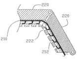
도 9 내지 도 12에서, 임플란트 몸체(200)는 세그먼트(220)들 및 지퍼 같은(zipper-like) 로킹 엘리먼트(210)를 가질 수 있으며, 지퍼 같은 로킹 엘리먼트(210)는 원위측 세그먼트(220)에 견고하게 부착되고 임플란트(200)의 모든 세그먼트들 내에 결합될 수 있다. 로킹 엘리먼트(210)의 근위측 단부(proximal end)는 임플란트 몸체(200)에 대해 후방으로(rearward direction) 당겨질 수 있다. 임플란트 몸체(200)는 리세스(222)들 또는 슬롯들을 가질 수 있다. 로킹 엘리먼트(210)는 하나의 스트립(strip)일 수 있으며, 예를 들어 금속(예컨대 니티놀(Nitinol) 또는 스테인리스 스틸)이나 플라스틱(예컨대 폴리에테르에테르케톤(PEEK), 초고분자량 폴리에틸렌(UHMWPE))을 사용하여 실행될 수 있다. 로킹 엘리먼트(210)는 일련의 탄력성 탭(212)들을 가질 수 있으며, 이 탄력성 탭(212)들은, 임플란트 몸체(200)의 대응되는 결합 엘리먼트(222)들 상에 래칭(latching)될 수 있다.9-12, the
도 11 내지 도 12는 두 개의 인접한 세그먼트(220)들 사이에서의 실제의 로킹 메카니즘을 보여준다. 도 11은 임플란트 몸체(200)의 2개의 세그먼트(220)들이 펼쳐진 상태에 있는 것을 보여주는데, 2개의 연이은 세그먼트(220)들 사이에는 노치 또는 틈(본 실시 예에서 V 형상임)이 있다. 일단 로킹 엘리먼트(210)가 세그먼트(220)들에 대해 후방으로(도 11의 화살표 R 방향으로) 당겨지면, 세그먼트(220)들의 축선 및 조임 엘리먼트(210)가 통과하는 채널 사이의 오프셋(offset) 때문에 세그먼트(220)들은 회전한다. 회전의 결과로 세그먼트(220)들은 도 12에 도시된 바와 같이 내부로 서로 밀착된다. 또한 도 12에 도시된 바와 같이 탄력성 탭(212)들은 슬롯(222)들 내부로 로킹되고, 그 결과 세그먼트(220)들은 서로 붙어서 튼튼하게 로킹이 이루어진다. 11-12 show the actual locking mechanism between two
일부 실시 예들에서는, 임플란트 몸체를 후방으로 당겨서 그 세그먼트(30)들을 굽히기 위해, 로킹 엘리먼트(50 (또는 210))로부터 독립된 텐션 엘리먼트(tensioning element)가 사용될 수 있다. 그러한 경우에, 먼저 디바이스(10)를 굽히는 데 텐션 엘리먼트가 사용되고, 그 다음, 로킹 엘리먼트(50)를 잡아당겨, 돌기부(60)들을 결합 엘리먼트(40)들과 짝짓게 함으로써 디바이스를 로킹할 수 있다. In some embodiments, a tensioning element independent from the locking element 50 (or 210) may be used to pull the implant body backwards to bend the
상기 실시 예들에서, 본 발명의 로킹 메카니즘은, 다중의(multiple) 로킹 엘리먼트(50 또는 210)들을 사용하여 더욱 향상될 수 있다. 이 경우, 세그먼트 내에 있는 임플란트 몸체(200 또는 20)의 다중의 돌기부들이, 임플란트 몸체의 각 세그먼트(220 또는 30)에 있는 다중의 결합 엘리먼트(222 또는 40)들과 결합하여 로킹된다. 하나의 예로, 상기 다중의 결합 엘리먼트들은 나란히 되어 있는 스트립 재질일 수 있다. In the above embodiments, the locking mechanism of the present invention can be further improved by using
본 발명의 의료 디바이스(10)는, 예컨대 의료 디바이스(10)가 펼쳐진 형상으로 있을 때, 의료 디바이스(10)를 수용하고 임플란트 몸체(20)를 펼쳐진 상태로 유지하게끔 크기가 정해진 도관(conduit)를 더 포함할 수 있다. 이 도관은 직선의 형상으로 되어 있을 수 있으며, 임플란트(10)의 외형에 꼭 맞게 되어 있을 수 있다. 이러한 도관이 비록 도 1 내지 도 3에는 도시되지 않았지만, 본 발명의 임플란트(10) 용으로 사용될 수 있는 도관의 예가 2006년 7월 13일 공개된 국제출원 공보 WO 2006/072941호의 도 2 및 도 3에 도시되어 있다. 임플란트 몸체(20) 및 로킹 엘리먼트(50)는, 상기 로킹 엘리먼트가 굽힘 배치 상태를 이루게끔 변형될 때, 연속된 각 세그먼트가 굽혀지고 로킹 엘리먼트의 돌기부들이 임플란트 몸체의 결합 엘리먼트들과 결합하고 로킹되도록 형성될 수 있다. The
도 6에서 임플란트 몸체가 펼쳐진 상태에 있는데, 이때 로킹 엘리먼트(50)의 돌기부(60)들은 반드시 임플란트 몸체(20)의 결합 엘리먼트(40)들 내에 위치하지 않을 수 있거나, 또는 결합 엘리먼트(40)들에 결합하지 않을 수 있다. 여기서 돌기부(60)들은 도 6에서 벌지(60)들로 묘사되어 있으며, 결합 엘리먼트(40)들은 도 6에서 소켓(40)들로 묘사되어 있다. 실지로, 로킹 엘리먼트(50)의 돌기부(60)들은 임플란트 몸체(20)의 결합 엘리먼트(40)들 내에 위치하지 않거나 이에 결합하지 않기가 쉽다. 도 7에서, 이미 굽혀진(30A, 30B) 세그먼트(30)들만이 벌지(60)들에 의해 결합된 결합 엘리먼트들 또는 소켓들(40)을 가지고 있다. 도 8에서, 굽혀진 세그먼트(30)들의 소켓(40)들 내에 벌지(60)들이 있음을 좀 더 쉽게 볼 수 있다. 도 6 내지 도 8을 좀 더 세밀히 보면, 특히 도 8을 보면, 임플란트(10) 내에서 벌지(60A)로부터 가장 이웃한 벌지(60B)까지의 길이는 세그먼트(30A)의 굽힘 부분(flexion section)(35A)으로부터 이웃 세그먼트(30B)의 굽힘 부분(35B)까지의 길이보다 짧을 수 있음을 알 수 있다. 도 6 내지 도 8의 실시 예에서, 벌지(60)로부터 벌지(60)(즉 이웃 벌지(60))까지의 길이는 실질적으로 균일할 수 있으며, 이와 유사하게 소켓으로부터 소켓(즉 이웃 소켓(40))까지의 길이도 실질적으로 균일할 수 있음을 유념해야 한다. 그러나 의료 디바이스가 나선형(helical)이거나 또는 평면이 아닌 실시 예에서, 또는 의료 디바이스에 불균일한 곡률이 필요한 경우에는, 비록 굽혀진 세그먼트들에서는 소켓에서 소켓까지의 거리가 여전히 벌지에서 벌지까지의 거리와 일치할 수 있더라도, 이들 거리들이 균일하지 않을 수 있다. In FIG. 6 the implant body is in the unfolded state, wherein the
연속된 세그먼트들(30A, 30B, 30C, 30D)이 굽혀짐에 따라, 조임 엘리먼트(50)의 대략적인 아치형 형상은, 임플란트 몸체(20)의 힌지(35)들의 대략적인 아치형 형상보다 작은 원호에 걸쳐질 수 있다. 왜냐하면, 굽힘 배치 상태에서 임플란트 몸체(20)의 조임 엘리먼트(50)는 대체적인 임플란트 몸체(20)의 내측(inward), 특히 힌지(35)들의 내측에 있기 때문이다. 이와 관련하여 "내측(inward)"이란, 임플란트(10)가 굽힘 배치 상태에 있을 때 임플란트(10)(로킹 엘리먼트(50) 및 임플란트 몸체(20))의 아치형 형상에 의해 만들어지는 원호/원의 중심에 상대적으로 더 가까움을 의미한다. 따라서, 펼쳐진 상태에서는 로킹 엘리먼트의 적어도 일부 벌지들은 소켓들 외부에, 힌지들 부분에 위치할 수 있으며, 굽힘 배치 상태에서는, 굽혀진 세그먼트들의 소켓들 내에 로킹 엘리먼트의 벌지들이 위치하게 된다. 굽혀진 각 세그먼트(30)는, 대응하는 소켓에 결합된 벌지(60)를 가질 수 있다. 도 8에 도시된 바와 같이 굽힘 배치 상태에서는, 소켓을 지닌 모든 굽혀진 세그먼트는 또한 그 안에 위치하는 벌지를 가진다. As the
비록 도면들에는, 임플란트(10)의 연장 방향(direction of elongation)이 힌지들과 실질적으로 동일 평면을 이루면서 그 평면에서 힌지(35)들에 수직을 이룬다고 말할 수 있는 실시 예들이 도시되어 있지만, 본 발명은, 굽힘 배치 상태에서 원위측 굽힘 세그먼트로부터 근위측 굽힘 세그먼트까지 이어지는 임플란트의 연장 방향이, 굽혀진 세그먼트들의 힌지들에 수직이 아닌 경우와 같은 비평면(nonplanar) 형태 또는 나선형 형태의 임플란트(10)에 대해서도 동등하게 적용될 수 있다. 본 발명의 로킹 장치가 없는 임플란트의 나선형 형태에 대한 예가, 2006년 7월 13일 공개된 본 출원인의 PCT 국제특허출원 공보 WO 2006/072941호에 기술되어 있으며(본 공보의 도 9A, 도 9B, 도 10 및 페이지 17 참조), 이 공보 내용은 참조에 의해 전체적으로 여기에 통합된다. 또한 이 공보에는, 본 발명의 안정적이고 확고한 로킹 장치는 없지만, 세그먼트(30)들 및 임플란트(10)에 대한 일반적인 특징들이 기술되어 있다.Although the figures show embodiments in which the direction of elongation of the
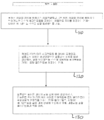
도 13에 도시된 바와 같이, 본 발명은 또한 대상자의 신체 내에 임플란트를 배치하는 방법(100)으로서 기술될 수 있다. 본 방법(100)은, 펼쳐진 상태의 양상을 취하게끔 힌지식으로 서로 연결되고 굽힘 배치 상태의 양상을 취하게끔 변형될 수 있는 다수의 세그먼트들을 포함하는 임플란트 몸체를 제공하는 제1단계(110)를 포함할 수 있는데, 상기 다수의 세그먼트들 각각은 결합 엘리먼트를 가진다. 제2단계(120)로 본 방법(100)은, 원위측 세그먼트에 고정된 로킹 엘리먼트를 제공하는 단계를 포함할 수 있는데, 이 로킹 엘리먼트는 임플란트 몸체의 연장 방향을 따라 임플란트 몸체를 따라 연장되며, 이 로킹 엘리먼트는, 임플란트 몸체의 결합 엘리먼트들 각각에 대응하는 돌기부들을 가질 수 있다. 본 방법(100)의 제3단계(130)에서, 임플란트 몸체를 대상자의 신체 내로 전진시킬 수 있다. 또한 임플란트 몸체가 굽힘 배치 상태로 변형되게끔 로킹 엘리먼트에 후방으로의 인장력을 가할 수 있다. 이로써, 돌기부들은 대응되는 결합 엘리먼트들과 짝을 이루게 되어, 해당되는 세그먼트들을 굽힘 배치 상태에 로킹할 수 있다. 또한 본 방법(100)의 일부 버전들(versions)은, 로킹 엘리먼트를 그의 고정점으로부터 해제시키고, 로킹 엘리먼트를 의료 디바이스로부터 잡아당겨 내는 단계를 포함할 수 있다. As shown in FIG. 13, the present invention may also be described as a method 100 for placing an implant within a subject's body. The method 100 includes a first step 110 of providing an implant body comprising a plurality of segments that are hingedly connected to one another to take an aspect of an unfolded state and that can be deformed to take an aspect of a bent arrangement. Wherein each of said plurality of segments has a coupling element. In a
세그먼트(30)들 사이의 굽힘 영역(35)들은 구조적으로 다양한 방식으로 실행될 수 있다. 대단히 바람직하게는 세그먼트(30)들 사이의 상호연결(interconnection)이 힌지식 상호연결로 되는 것이며, 이러한 힌지식 상호연결은, 재료의 원 블록(initial block)으로부터 리세스들을 잘라내거나, 또는 사출 또는 성형 프로세스 중에 일체형 힌지(35)들을 세그먼트(30)들과 일체형으로 형성시킴으로써 이루어질 수 있다. 상기 리세스들은 평행한 측면을 가진 V 형상의 노치들(V-shaped notches)이나 여타 적절한 형태로 될 수 있다. 대단히 바람직하게는, 임플란트의 곡이 진 배치 형태(curved deployed form)가, 기본적으로 밀착된 세그먼트들 사이에 공간들을 가지도록 V 형상의 슬롯들이 사용되는 것이다. 그러나 세그먼트(30)들이 부착되는 별도의 구조물(예컨대 "백본(backbone)")에 의해 힌지식 상호연결이 제공되는 것과 같은 대안의 실행들(alternative impletations)도 본 발명의 범주에 속하는 것이다. 이러한 후자의 경우, 백본은 세그먼트들 자신과는 다른 재질로 이루어질 수 있으며, 의도한 적용 분야에 따라 선정될 수 있다. 백본에 대한 재료 선택에는 금속 재료들, 다양한 플라스틱류, 여타 폴리머들(polymers) 및 직물들(fabrics)이 포함될 수 있는데 이들에 국한되는 것은 아니다. The
상술한 굽힘 배치 상태(flexed deployed state)는 또한 곡이 진 배치 형태(curved deployed form)로도 칭한다. 그러나 여기서 일컫는 "굽힘(flexing)"이란, 비록 일부 실시 예들에서 세그먼트들의 실제적 벤딩(bending)이 있을 수 있지만, 반드시 세그먼트들의 실제적 벤딩(bending)을 수반하는 것은 아니다. 게다가 상기 곡이 진 배치 형태는, 특히 세그먼트들의 수가 비교적 적은 경우, 반드시 완전한 곡선(perfect curve)을 표현하는 것은 아니다. 따라서 임플란트 몸체(10)의 곡이 진 배치 형태를 일컫는 굽힘 배치 형태는 바람직하게는 대략적인 아치형 형태를 이루는 것이며, 이는 통상적으로, 실질적인 "U 형상(U-shaped)"의 형태로 나타나는 것을 형성하게끔 약 180 도를 빙 둘러 연장될 수 있다. 여기서 "U 형상"이란 용어는 일반적으로, 양 측면 부분들의 크기나 형상이나 기하학적 구조에 대해선 구체적으로 지정하지 않고, 대략 180 도(즉 180 도 플러스 마이너스 20 도)를 통해 돌아가는 내측 부분(medial portion)을 가지는 임의의 형상을 칭하는 데 사용된다. (첨언하건대 문자 "u" 자체는 많은 서체에 있어서 비대칭임을 알 수 있다.).
The flexed deployed state described above is also referred to as a curved deployed form. However, the term "flexing" as used herein does not necessarily involve actual bending of segments, although in some embodiments there may be actual bending of the segments. Furthermore, the curved arrangement does not necessarily represent a perfect curve, especially when the number of segments is relatively small. Thus, the bend arrangement, which refers to the curved configuration of the
상술한 내용들은 단지 예시적인 것이며, 특허청구범위에 규정된 본 발명의 범위 내에서 많은 다른 실시 예들이 가능할 것이다
The foregoing is merely illustrative, and many other embodiments are possible within the scope of the invention as defined in the claims.
Claims (23)
(b) 상기 적어도 2개의 결합 엘리먼트들에 대응하는 적어도 2개의 돌기부(projection)들을 가지며, 상기 임플란트 몸체의 한 세그먼트에 고정되는 기다란(elongated) 로킹 엘리먼트(locking element);를 포함하며,
상기 임플란트 몸체 및 로킹 엘리먼트는, 상기 로킹 엘리먼트가 상기 굽힘 배치 상태에 도달하게끔 변형될 때, 로킹 엘리먼트의 적어도 2개의 돌기부들이 임플란트 몸체의 적어도 2개의 결합 엘리먼트들과 결합하여 로킹되도록 형성되어 있으며, 연속된 세그먼트들이 굽혀지고 로킹된 뒤에 각 로킹 세그먼트(locking segment)는 로킹된 상태로 유지되며, 상기 로킹 장치(locking arrangement)는 상기 로킹 엘리먼트를 상기 임플란트 몸체에 대해 로킹하는 데 효과적이여서, 상기 임플란트를 상기 굽힘 배치 상태로 유지하는 것을 특징으로 하는 의료 디바이스(medical device).
(a) an implant body comprising a plurality of segments interconnected to take the form of a straightened state and a flexed deployed state, wherein the implant body is An implant body formed with at least two engagement elements, each of the at least two other segments having a coupling element; And
(b) an elongated locking element having at least two projections corresponding to the at least two coupling elements, the elongated locking element being secured to one segment of the implant body;
The implant body and the locking element are formed such that when the locking element is deformed to reach the bending arrangement, the at least two protrusions of the locking element engage and lock with at least two engagement elements of the implant body and are continuous After each segment is bent and locked, each locking segment remains locked and the locking arrangement is effective to lock the locking element against the implant body, thereby locking the implant. A medical device characterized by maintaining in a bent arrangement.
상기 로킹 엘리먼트는 상기 임플란트 몸체의 원위측(distal) 세그먼트에 고정되고, 상기 임플란트 몸체 및 상기 로킹 엘리먼트는, 상기 로킹 엘리먼트에 인장력이 가해지면 상기 임플란트 몸체는 상기 펼쳐진 상태에서 상기 굽힘 배치 상태로 편향시키게끔 형성된 것을 특징으로 하는 의료 디바이스.
The method of claim 1,
The locking element is secured to the distal segment of the implant body, and the implant body and the locking element are biased into the bent arrangement in the unfolded state when tension is applied to the locking element. Medical device, characterized in that formed.
상기 임플란트 몸체의 적어도 3개의 세그먼트들 각각은 적어도 하나의 결합 엘리먼트를 지니고 형성되어 있으며, 조임 엘리먼트(tightening element)는 로킹 장치를 제공하기 위해 상기 임플란트 몸체의 결합 엘리먼트들 중 적어도 하나와 대응하여 결합하는 돌기부를 가지는 것을 특징으로 하는 의료 디바이스.
The method of claim 1,
Each of the at least three segments of the implant body is formed with at least one engagement element, the tightening element correspondingly engaging at least one of the engagement elements of the implant body to provide a locking device. A medical device having a protrusion.
상기 임플란트 몸체의 적어도 1/3 세그먼트들 각각은 적어도 하나의 결합 엘리먼트를 지니고 형성되어 있으며, 조임 엘리먼트는 로킹 장치를 제공하기 위해 상기 임플란트 몸체의 결합 엘리먼트들 각각과 대응하여 결합하는 돌기부를 가지는 것을 특징으로 하는 의료 디바이스.
The method of claim 1,
Each of the at least one third segments of the implant body is formed with at least one engagement element, the tightening element having a protrusion correspondingly corresponding to each of the engagement elements of the implant body to provide a locking device. Medical device.
매 4개의 연속된 세그먼트들 중 적어도 하나의 각각은 결합 엘리먼트를 가지고, 대응하는 조임 엘리먼트의 돌기부와 로킹되는 것을 특징으로 하는 의료 디바이스.
The method of claim 1,
Wherein at least one of every four successive segments has a coupling element and is locked with the protrusion of the corresponding tightening element.
상기 임플란트 몸체의 원위측 세그먼트를 제외한 세그먼트들 각각은 적어도 하나의 결합 엘리먼트를 지니고 형성되어 있으며, 조임 엘리먼트는 로킹 장치를 제공하기 위해 상기 임플란트 몸체의 결합 엘리먼트들의 적어도 2개와 대응하여 결합하는 돌기부를 가지는 것을 특징으로 하는 의료 디바이스.
The method of claim 1,
Each of the segments other than the distal segment of the implant body is formed with at least one coupling element, the tightening element having protrusions correspondingly corresponding to at least two of the coupling elements of the implant body to provide a locking device. A medical device, characterized in that.
대부분의 세그먼트들은 적어도 하나의 결합 엘리먼트를 지니고 형성되어 있으며, 조임 엘리먼트는 상기 적어도 하나의 결합 엘리먼트 각각에 대응하는 돌기부를 가지는 것을 특징으로 하는 의료 디바이스.
The method of claim 1,
Most segments are formed with at least one coupling element, wherein the tightening element has a protrusion corresponding to each of the at least one coupling element.
상기 돌기부들은 이빨들(teeth)이고, 상기 결합 엘리먼트들은 스텝들(steps)인 것을 특징으로 하는 의료 디바이스.
The method of claim 1,
And the protrusions are teeth and the coupling elements are steps.
상기 돌기부들은 탄력성의 탭들(elastic tabs)이고, 상기 결합 엘리먼트들은 상보적인(complementary) 리세스들(recesses)인 것을 특징으로 하는 의료 디바이스.
The method of claim 1,
Wherein the protrusions are elastic tabs and the coupling elements are complementary recesses.
각 세그먼트는 적어도 하나의 상보적인 리세스를 가지며, 각 세그먼트가 굽힘 배치 상태로 굽혀질 때, 적어도 하나의 탄력성의 탭이 각 세그먼트의 적어도 하나의 상보적인 리세스와 로킹되는 것을 특징으로 하는 의료 디바이스.
10. The method of claim 9,
Wherein each segment has at least one complementary recess, and when each segment is bent in a bent arrangement, at least one resilient tab is locked with at least one complementary recess of each segment.
상기 임플란트를 수용하고 상기 임플란트 몸체를 상기 펼쳐진 상태로 유지하게끔 크기가 정해진 도관(conduit)을 더 포함하는 것을 특징으로 하는 의료 디바이스.
The method of claim 1,
And a conduit sized to receive the implant and maintain the implant body in the unfolded state.
(b) 상기 적어도 2개의 소켓들에 대응하는 적어도 2개의 벌지(bulge)들을 가지며, 상기 임플란트 몸체의 한 세그먼트에 고정되는 기다란 로킹 엘리먼트;를 포함하며,
상기 임플란트 몸체 및 상기 로킹 엘리먼트는, 상기 로킹 엘리먼트가 상기 굽힘 배치 상태에 도달하게끔 변형될 때, 상기 로킹 엘리먼트의 적어도 2개의 벌지들이 상기 임플란트 몸체의 적어도 2개의 소켓들과 결합하여 로킹되도록 형성되어 있으며, 로킹 장치는, 다수의 세그먼트들에서 상기 로킹 엘리먼트를 상기 임플란트 몸체에 대해 로킹하는 데 효과적이여서, 상기 임플란트를 상기 굽힘 배치 상태로 유지하는 것을 특징으로 하는 의료 디바이스(medical device).
(a) an implant body comprising a plurality of segments interconnected to take the form of an unfolded and bent arrangement, wherein the implant body has at least two sockets, each of the at least two other segments having a socket; Branches, implant body; And
(b) an elongate locking element having at least two bulges corresponding to the at least two sockets and fixed to one segment of the implant body;
The implant body and the locking element are formed such that when the locking element is deformed to reach the bending arrangement, at least two bulges of the locking element engage and lock with at least two sockets of the implant body. And the locking device is effective to lock the locking element against the implant body in a plurality of segments, thereby holding the implant in the bent arrangement.
상기 로킹 엘리먼트는 상기 임플란트 몸체의 원위측 세그먼트에 고정되고, 상기 임플란트 몸체 및 상기 로킹 엘리먼트는, 상기 로킹 엘리먼트에 인장력이 가해지면 상기 임플란트 몸체를 상기 펼쳐진 상태에서 상기 굽힘 배치 상태로 편향시키게끔 형성된 것을 특징으로 하는 의료 디바이스.
The method of claim 12,
Wherein the locking element is secured to the distal segment of the implant body, wherein the implant body and the locking element are configured to deflect the implant body from the unfolded state to the bent arrangement when tension is applied to the locking element. A medical device characterized by the above-mentioned.
상기 임플란트 몸체의 세그먼트들 중 적어도 1/2의 각각은 적어도 하나의 소켓을 지니고 형성되어 있으며, 조임 엘리먼트(tightening element)는 로킹 장치를 제공하기 위해 실질적으로 모든 소켓들에 대응하는 벌지를 가지는 것을 특징으로 하는 의료 디바이스.
The method of claim 12,
Each of at least half of the segments of the implant body are formed with at least one socket, and the tightening element has a bulge corresponding to substantially all of the sockets to provide a locking device. Medical device.
벌지로부터 가장 이웃한 벌지까지의 길이는, 세그먼트의 굽힘 영역(flexion region)으로부터 이웃한 세그먼트의 굽힘 영역까지의 길이보다 짧은 것을 특징으로 하는 의료 디바이스.
The method of claim 12,
The length from the bulge to the nearest bulge is shorter than the length from the flexion region of the segment to the bend region of the neighboring segment.
벌지로부터 벌지까지의 길이가 실질적으로 균일하고, 소켓으로부터 소켓까지의 길이가 실질적으로 균일한 것을 특징으로 하는 의료 디바이스.
The method of claim 12,
A medical device, characterized in that the length from the bulge to the bulge is substantially uniform and the length from the socket to the socket is substantially uniform.
상기 펼쳐진 상태에서는 조임 엘리먼트의 적어도 일부 벌지들이 소켓들의 바깥 굽힘 영역 부분에 위치하며, 상기 굽힘 배치 상태에서는 조임 엘리먼트의 벌지들이, 굽혀진 세그먼트들의 소켓들 내에 위치하는 것을 특징으로 하는 의료 디바이스.
The method of claim 12,
Wherein in the unfolded state at least some bulges of the tightening element are located in the outer bent area portion of the sockets, and in the bent arrangement the bulges of the tightening element are located in the sockets of the bent segments.
상기 굽힘 배치 상태에서는, 소켓을 가지는 모든 굽혀진 세그먼트는 또한 소켓 내에 위치하는 벌지를 가지는 것을 특징으로 하는 의료 디바이스.
The method of claim 12,
In the bent arrangement, all bent segments with sockets also have a bulge located within the socket.
상기 의료 디바이스는 나선형(helical)인 것을 특징으로 하는 의료 디바이스.
20. The method of claim 19,
And the medical device is helical.
상기 의료 장치를 수용하고 상기 임플란트 몸체를 상기 펼쳐진 상태로 유지하게끔 크기가 정해진 도관을 더 포함하는 것을 특징으로 하는 의료 디바이스.
The method of claim 12,
And a conduit sized to receive the medical device and to maintain the implant body in the unfolded state.
상기 벌지들 및 소켓들은 구형(spherical)인 것을 특징으로 하는 의료 디바이스.
The method of claim 12,
And the bulges and sockets are spherical.
(a) 펼쳐진 상태의 양상을 취하게끔 상호연결되고 굽힘 배치 상태의 양상을 취하게끔 변형가능한 다수의 세그먼트들을 포함하는 임플란트 몸체로서, 다수의 세그먼트들 각각은 결합 엘리먼트를 가지는, 임플란트 몸체를 제공하는 단계;
(b) 적어도 2개의 다른 세그먼트들 중 하나에 고정되고, 상기 임플란트 몸체의 연장방향으로 상기 임플란트 몸체를 따라 연장되며, 결합 엘리먼트들 각각에 대응하는 돌기부들을 가지는 로킹 엘리먼트를 제공하는 단계; 및
(c) 상기 임플란트 몸체를 대상이 되는 신체 내에 전진시키고, 상기 임플란트 몸체가 상기 굽힘 배치 상태로 변형되도록 상기 로킹 엘리먼트에 후방으로의 인장력(rearward tention)을 가하는 단계;를 포함하며,
상기 돌기부들은, 해당하는 세그먼트들을 상기 굽힘 배치 상태에 로킹하기 위해, 대응되는 상기 결합 엘리먼트들과 짝을 이루는 것을 특징으로 하는 방법.
A method of disposing a medical device inside a target body, the method comprising:
(a) providing an implant body comprising a plurality of segments interconnected and deformable to take an aspect of an unfolded state, each segment having a coupling element; ;
(b) providing a locking element secured to one of the at least two different segments, extending along the implant body in the direction of extension of the implant body, the locking element having protrusions corresponding to each of the coupling elements; And
(c) advancing the implant body into a target body and applying a rearward tention to the locking element such that the implant body is deformed into the bending arrangement;
And the protrusions mate with corresponding mating elements for locking corresponding segments in the bending arrangement.
로킹 엘리먼트를 고정부로부터 해제하는 단계 및, 상기 로킹 엘리먼트를 의료 디바이스로부터 빼내는 단계를 더 포함하는 것을 특징으로 하는 방법.
The method of claim 22,
Releasing the locking element from the fixation, and removing the locking element from the medical device.
Applications Claiming Priority (3)
| Application Number | Priority Date | Filing Date | Title |
|---|---|---|---|
| US30485710P | 2010-02-16 | 2010-02-16 | |
| US61/304,857 | 2010-02-16 | ||
| PCT/IB2011/050648 WO2011101793A1 (en) | 2010-02-16 | 2011-02-16 | Medical device lock mechanism |
Publications (1)
| Publication Number | Publication Date |
|---|---|
| KR20120138762A true KR20120138762A (en) | 2012-12-26 |
Family
ID=43919605
Family Applications (1)
| Application Number | Title | Priority Date | Filing Date |
|---|---|---|---|
| KR20127023817A KR20120138762A (en) | 2010-02-16 | 2011-02-16 | Medical device lock mechanism |
Country Status (9)
| Country | Link |
|---|---|
| US (3) | US9017408B2 (en) |
| EP (2) | EP2536364A1 (en) |
| JP (1) | JP5774028B2 (en) |
| KR (1) | KR20120138762A (en) |
| CN (1) | CN102933178A (en) |
| CA (1) | CA2789961A1 (en) |
| IL (2) | IL221455A0 (en) |
| RU (1) | RU2012138578A (en) |
| WO (2) | WO2011101793A1 (en) |
Families Citing this family (66)
| Publication number | Priority date | Publication date | Assignee | Title |
|---|---|---|---|---|
| US6793678B2 (en) | 2002-06-27 | 2004-09-21 | Depuy Acromed, Inc. | Prosthetic intervertebral motion disc having dampening |
| WO2004073563A2 (en) | 2003-02-14 | 2004-09-02 | Depuy Spine, Inc. | In-situ formed intervertebral fusion device |
| US20040267367A1 (en) | 2003-06-30 | 2004-12-30 | Depuy Acromed, Inc | Intervertebral implant with conformable endplate |
| US20070162132A1 (en) | 2005-12-23 | 2007-07-12 | Dominique Messerli | Flexible elongated chain implant and method of supporting body tissue with same |
| US8034110B2 (en) | 2006-07-31 | 2011-10-11 | Depuy Spine, Inc. | Spinal fusion implant |
| WO2008070863A2 (en) | 2006-12-07 | 2008-06-12 | Interventional Spine, Inc. | Intervertebral implant |
| US9039768B2 (en) | 2006-12-22 | 2015-05-26 | Medos International Sarl | Composite vertebral spacers and instrument |
| FR2917287B1 (en) * | 2007-06-15 | 2010-09-03 | Ldr Medical | INTERVERTEBRAL PROSTHESIS |
| US8900307B2 (en) | 2007-06-26 | 2014-12-02 | DePuy Synthes Products, LLC | Highly lordosed fusion cage |
| US7922767B2 (en) * | 2007-07-07 | 2011-04-12 | Jmea Corporation | Disk fusion implant |
| US20090088789A1 (en) | 2007-09-28 | 2009-04-02 | O'neil Michael J | Balloon With Shape Control For Spinal Procedures |
| JP5441922B2 (en) | 2008-01-17 | 2014-03-12 | ジンテス ゲゼルシャフト ミット ベシュレンクテル ハフツング | Inflatable intervertebral implant and related manufacturing method |
| US20090248092A1 (en) | 2008-03-26 | 2009-10-01 | Jonathan Bellas | Posterior Intervertebral Disc Inserter and Expansion Techniques |
| EP2262449B1 (en) | 2008-04-05 | 2020-03-11 | Synthes GmbH | Expandable intervertebral implant |
| US9526620B2 (en) | 2009-03-30 | 2016-12-27 | DePuy Synthes Products, Inc. | Zero profile spinal fusion cage |
| US9028553B2 (en) | 2009-11-05 | 2015-05-12 | DePuy Synthes Products, Inc. | Self-pivoting spinal implant and associated instrumentation |
| US9168138B2 (en) | 2009-12-09 | 2015-10-27 | DePuy Synthes Products, Inc. | Aspirating implants and method of bony regeneration |
| US9393129B2 (en) | 2009-12-10 | 2016-07-19 | DePuy Synthes Products, Inc. | Bellows-like expandable interbody fusion cage |
| US8979860B2 (en) | 2010-06-24 | 2015-03-17 | DePuy Synthes Products. LLC | Enhanced cage insertion device |
| US8845733B2 (en) | 2010-06-24 | 2014-09-30 | DePuy Synthes Products, LLC | Lateral spondylolisthesis reduction cage |
| TW201215379A (en) | 2010-06-29 | 2012-04-16 | Synthes Gmbh | Distractible intervertebral implant |
| US20120078373A1 (en) | 2010-09-23 | 2012-03-29 | Thomas Gamache | Stand alone intervertebral fusion device |
| US11529241B2 (en) | 2010-09-23 | 2022-12-20 | DePuy Synthes Products, Inc. | Fusion cage with in-line single piece fixation |
| US20120078372A1 (en) | 2010-09-23 | 2012-03-29 | Thomas Gamache | Novel implant inserter having a laterally-extending dovetail engagement feature |
| US9402732B2 (en) | 2010-10-11 | 2016-08-02 | DePuy Synthes Products, Inc. | Expandable interspinous process spacer implant |
| AU2012231108B2 (en) | 2011-03-22 | 2015-10-22 | DePuy Synthes Products, LLC | Universal trial for lateral cages |
| WO2013043850A2 (en) * | 2011-09-20 | 2013-03-28 | The University Of Toledo | Expandable inter-vertebral cage and method of installing same |
| US9198765B1 (en) | 2011-10-31 | 2015-12-01 | Nuvasive, Inc. | Expandable spinal fusion implants and related methods |
| US9226764B2 (en) | 2012-03-06 | 2016-01-05 | DePuy Synthes Products, Inc. | Conformable soft tissue removal instruments |
| US9271836B2 (en) | 2012-03-06 | 2016-03-01 | DePuy Synthes Products, Inc. | Nubbed plate |
| US20150173910A1 (en) * | 2012-08-29 | 2015-06-25 | Nlt Spine Ltd | Method and system for implants |
| US9445918B1 (en) | 2012-10-22 | 2016-09-20 | Nuvasive, Inc. | Expandable spinal fusion implants and related instruments and methods |
| US10182921B2 (en) | 2012-11-09 | 2019-01-22 | DePuy Synthes Products, Inc. | Interbody device with opening to allow packing graft and other biologics |
| US10022245B2 (en) | 2012-12-17 | 2018-07-17 | DePuy Synthes Products, Inc. | Polyaxial articulating instrument |
| US9522070B2 (en) | 2013-03-07 | 2016-12-20 | Interventional Spine, Inc. | Intervertebral implant |
| US9795493B1 (en) | 2013-03-15 | 2017-10-24 | Nuvasive, Inc. | Expandable intervertebral implant and methods of use thereof |
| WO2015009998A1 (en) * | 2013-07-18 | 2015-01-22 | The University Of Toledo | Expandable inter-vertebral cage and method of installing same |
| CN106239136B (en) * | 2013-09-11 | 2018-06-19 | 科森科技东台有限公司 | The efficient assembly system of high stability |
| CN103465020B (en) * | 2013-09-11 | 2016-01-06 | 昆山科森科技股份有限公司 | The accurate apparatus for assembling of medical assembly |
| CN104644291B (en) * | 2013-11-18 | 2017-12-12 | 宝楠生技股份有限公司 | The intervertebral fusion fixing device of memory-type |
| US9901457B2 (en) | 2014-10-16 | 2018-02-27 | Jmea Corporation | Coiling implantable prostheses |
| CN107405201B (en) * | 2015-01-09 | 2020-10-27 | 孚美公司 | Rigid segmented flexible anchor |
| US11426290B2 (en) | 2015-03-06 | 2022-08-30 | DePuy Synthes Products, Inc. | Expandable intervertebral implant, system, kit and method |
| CN104921849B (en) * | 2015-07-15 | 2017-08-04 | 王洪伟 | Invasive lumbar fusion device |
| USD790310S1 (en) | 2015-09-21 | 2017-06-27 | Lawrence St. Peter | Handle adapter for a bench vice |
| US11833034B2 (en) | 2016-01-13 | 2023-12-05 | Shifamed Holdings, Llc | Prosthetic cardiac valve devices, systems, and methods |
| WO2018002715A2 (en) | 2016-06-28 | 2018-01-04 | Eit Emerging Implant Technologies Gmbh | Expandable and angularly adjustable articulating intervertebral cages |
| WO2018002711A2 (en) | 2016-06-28 | 2018-01-04 | Eit Emerging Implant Technologies Gmbh | Expandable, angularly adjustable intervertebral cages |
| CN106308983B (en) * | 2016-08-31 | 2018-09-14 | 广州爱锘德医疗器械有限公司 | Fusion device, operator and vertebral fusion device |
| US10888433B2 (en) | 2016-12-14 | 2021-01-12 | DePuy Synthes Products, Inc. | Intervertebral implant inserter and related methods |
| US10398563B2 (en) | 2017-05-08 | 2019-09-03 | Medos International Sarl | Expandable cage |
| US11344424B2 (en) | 2017-06-14 | 2022-05-31 | Medos International Sarl | Expandable intervertebral implant and related methods |
| US10940016B2 (en) | 2017-07-05 | 2021-03-09 | Medos International Sarl | Expandable intervertebral fusion cage |
| US10966843B2 (en) | 2017-07-18 | 2021-04-06 | DePuy Synthes Products, Inc. | Implant inserters and related methods |
| US11045331B2 (en) | 2017-08-14 | 2021-06-29 | DePuy Synthes Products, Inc. | Intervertebral implant inserters and related methods |
| NL2019711B1 (en) * | 2017-10-12 | 2019-04-23 | Am Solutions Holding B V | A spinal implant |
| JP2022504241A (en) | 2018-10-05 | 2022-01-13 | シファメド・ホールディングス・エルエルシー | Artificial heart valve device, system, and method |
| JP2022505273A (en) * | 2018-10-19 | 2022-01-14 | シファメド・ホールディングス・エルエルシー | Adjustable medical device |
| US11446156B2 (en) | 2018-10-25 | 2022-09-20 | Medos International Sarl | Expandable intervertebral implant, inserter instrument, and related methods |
| WO2020191216A1 (en) | 2019-03-19 | 2020-09-24 | Shifamed Holdings, Llc | Prosthetic cardiac valve devices, systems, and methods |
| US11426286B2 (en) | 2020-03-06 | 2022-08-30 | Eit Emerging Implant Technologies Gmbh | Expandable intervertebral implant |
| CN112120778B (en) * | 2020-09-17 | 2022-03-25 | 山东冠龙医疗用品有限公司 | Centrum struts filling device and propeller |
| WO2022178759A1 (en) * | 2021-02-25 | 2022-09-01 | 上海三友医疗器械股份有限公司 | Fusion cage and installation tool therefor |
| US11850160B2 (en) | 2021-03-26 | 2023-12-26 | Medos International Sarl | Expandable lordotic intervertebral fusion cage |
| US11752009B2 (en) | 2021-04-06 | 2023-09-12 | Medos International Sarl | Expandable intervertebral fusion cage |
| CN113244027B (en) * | 2021-06-25 | 2021-09-24 | 珠海维尔康生物科技有限公司 | Minimally invasive fence type deformable fusion device used under endoscope |
Family Cites Families (16)
| Publication number | Priority date | Publication date | Assignee | Title |
|---|---|---|---|---|
| EP2623056B1 (en) | 2005-01-05 | 2016-04-20 | NLT Spine Ltd. | Device for introduction into a body |
| US20070162135A1 (en) | 2005-06-15 | 2007-07-12 | Jerome Segal | Mechanical apparatus and method for artificial disc replacement |
| US7666226B2 (en) | 2005-08-16 | 2010-02-23 | Benvenue Medical, Inc. | Spinal tissue distraction devices |
| WO2008103781A2 (en) | 2007-02-21 | 2008-08-28 | Benvenue Medical, Inc. | Devices for treating the spine |
| FI20065474L (en) | 2006-07-04 | 2008-01-05 | Head Inhimillinen Tekijae Oy | A method for processing audio information |
| US8025697B2 (en) | 2006-09-21 | 2011-09-27 | Custom Spine, Inc. | Articulating interbody spacer, vertebral body replacement |
| US7947078B2 (en) * | 2007-01-09 | 2011-05-24 | Nonlinear Technologies Ltd. | Devices for forming curved or closed-loop structures |
| EP2099390A2 (en) * | 2007-01-09 | 2009-09-16 | Nonlinear Technologies Ltd. | Devices for forming curved or closed-loop structures |
| ES2757819T3 (en) * | 2007-02-21 | 2020-04-30 | Benvenue Medical Inc | Devices to treat the spine |
| US8021429B2 (en) * | 2007-03-08 | 2011-09-20 | Zimmer Spine, Inc. | Deployable segmented TLIF device |
| US20080249628A1 (en) * | 2007-04-09 | 2008-10-09 | Moti Altarac | Multi-component interbody device |
| US20090012612A1 (en) | 2007-04-10 | 2009-01-08 | David White | Devices and methods for push-delivery of implants |
| FR2917287B1 (en) | 2007-06-15 | 2010-09-03 | Ldr Medical | INTERVERTEBRAL PROSTHESIS |
| US8672977B2 (en) | 2007-08-09 | 2014-03-18 | Nlt Spine Ltd. | Device and method for spinous process distraction |
| US8951546B2 (en) | 2008-12-23 | 2015-02-10 | Surmodics Pharmaceuticals, Inc. | Flexible implantable composites and implants comprising same |
| CA2805476A1 (en) * | 2010-07-21 | 2012-01-26 | Nlt Spine Ltd. | Spinal surgery implants and delivery system |
-
2011
- 2011-02-16 EP EP20110708330 patent/EP2536364A1/en not_active Withdrawn
- 2011-02-16 US US13/579,292 patent/US9017408B2/en active Active
- 2011-02-16 RU RU2012138578/14A patent/RU2012138578A/en not_active Application Discontinuation
- 2011-02-16 US US13/521,747 patent/US20150112436A1/en not_active Abandoned
- 2011-02-16 EP EP20110707919 patent/EP2536363A1/en not_active Withdrawn
- 2011-02-16 CN CN2011800190744A patent/CN102933178A/en active Pending
- 2011-02-16 JP JP2012552517A patent/JP5774028B2/en active Active
- 2011-02-16 WO PCT/IB2011/050648 patent/WO2011101793A1/en active Application Filing
- 2011-02-16 CA CA 2789961 patent/CA2789961A1/en not_active Abandoned
- 2011-02-16 KR KR20127023817A patent/KR20120138762A/en not_active Application Discontinuation
- 2011-02-16 WO PCT/IB2011/050647 patent/WO2011101792A1/en active Application Filing
-
2012
- 2012-08-14 IL IL221455A patent/IL221455A0/en unknown
- 2012-08-14 IL IL221457A patent/IL221457A0/en unknown
-
2015
- 2015-03-22 US US14/664,867 patent/US9662222B2/en active Active
Also Published As
| Publication number | Publication date |
|---|---|
| EP2536363A1 (en) | 2012-12-26 |
| US9017408B2 (en) | 2015-04-28 |
| EP2536364A1 (en) | 2012-12-26 |
| US9662222B2 (en) | 2017-05-30 |
| CA2789961A1 (en) | 2011-08-25 |
| US20150209151A1 (en) | 2015-07-30 |
| WO2011101793A1 (en) | 2011-08-25 |
| JP2013526898A (en) | 2013-06-27 |
| IL221455A0 (en) | 2012-10-31 |
| US20130035762A1 (en) | 2013-02-07 |
| CN102933178A (en) | 2013-02-13 |
| JP5774028B2 (en) | 2015-09-02 |
| IL221457A0 (en) | 2012-10-31 |
| US20150112436A1 (en) | 2015-04-23 |
| WO2011101792A1 (en) | 2011-08-25 |
| RU2012138578A (en) | 2014-03-27 |
Similar Documents
| Publication | Publication Date | Title |
|---|---|---|
| KR20120138762A (en) | Medical device lock mechanism | |
| US8672977B2 (en) | Device and method for spinous process distraction | |
| CN107405142B (en) | Suture fixing device | |
| US9345518B2 (en) | Bone holding device | |
| JP4927816B2 (en) | Ratchet type fixing plate | |
| CN110740695A (en) | Surgical clip and clip applier | |
| CN110811743A (en) | Ligation clip with improved hinge part | |
| JP5078912B2 (en) | Stomach ring | |
| KR20080040620A (en) | Interspinous process implant with a slide-in distraction piece and method of implantation | |
| EP2320818A1 (en) | Crimp with an insert to hold a cable | |
| BR112013003402B1 (en) | surgical stapling instrument | |
| JP2023001233A (en) | surgical clip | |
| AU2020405150B2 (en) | Surgical clip | |
| CN110418616B (en) | Proximal femur hook plate | |
| US9943304B2 (en) | Suture anchor management | |
| CN104918568A (en) | Locking member for a bone fixation device | |
| CN113730257A (en) | Devices and methods for percutaneous endoscopic gastrostomy and other ostomy procedures | |
| US20120271352A1 (en) | Facet joint implant | |
| JP2021508508A (en) | Orthopedic implants and fixation systems | |
| US20220265261A1 (en) | Knotless instability devices and methods for soft tissue repair | |
| WO2017152026A1 (en) | Push-in anchor | |
| CN112790813A (en) | Ligating clip assembly | |
| CN112971899B (en) | Delivery sheath and medical instrument | |
| CN117157119A (en) | Fixing device for catheter | |
| WO2014173664A2 (en) | Apparatus and methods for securing together bone fragments |
Legal Events
| Date | Code | Title | Description |
|---|---|---|---|
| WITN | Application deemed withdrawn, e.g. because no request for examination was filed or no examination fee was paid |