KR20120121774A - Healthmachine - Google Patents
Healthmachine Download PDFInfo
- Publication number
- KR20120121774A KR20120121774A KR1020110039770A KR20110039770A KR20120121774A KR 20120121774 A KR20120121774 A KR 20120121774A KR 1020110039770 A KR1020110039770 A KR 1020110039770A KR 20110039770 A KR20110039770 A KR 20110039770A KR 20120121774 A KR20120121774 A KR 20120121774A
- Authority
- KR
- South Korea
- Prior art keywords
- bench
- handle
- connecting rod
- weight
- support
- Prior art date
Links
Images


Classifications
-
- A—HUMAN NECESSITIES
- A63—SPORTS; GAMES; AMUSEMENTS
- A63B—APPARATUS FOR PHYSICAL TRAINING, GYMNASTICS, SWIMMING, CLIMBING, OR FENCING; BALL GAMES; TRAINING EQUIPMENT
- A63B21/00—Exercising apparatus for developing or strengthening the muscles or joints of the body by working against a counterforce, with or without measuring devices
- A63B21/06—User-manipulated weights
- A63B21/078—Devices for bench press exercises, e.g. supports, guiding means
-
- A—HUMAN NECESSITIES
- A63—SPORTS; GAMES; AMUSEMENTS
- A63B—APPARATUS FOR PHYSICAL TRAINING, GYMNASTICS, SWIMMING, CLIMBING, OR FENCING; BALL GAMES; TRAINING EQUIPMENT
- A63B21/00—Exercising apparatus for developing or strengthening the muscles or joints of the body by working against a counterforce, with or without measuring devices
- A63B21/40—Interfaces with the user related to strength training; Details thereof
- A63B21/4027—Specific exercise interfaces
- A63B21/4033—Handles, pedals, bars or platforms
- A63B21/4035—Handles, pedals, bars or platforms for operation by hand
Abstract
Description
본 발명은 상체 근력운동에 사용되는 운동기구에 관한 것이다.The present invention relates to an exercise device used for upper body strength exercise.
일반적으로 폭이 좁은 벤치에 드러누워 역기를 두 팔로 떠받치고 가슴 위에서 올렸다 내렸다 하는 웨이트 트레이닝기구를 벤치프레스라 한다. 벤치프레스 누워서 역기를 들어 올리는 방식으로 가슴 운동을 하는 것이 일반적이다. In general, a bench press is a weight training device that lays down on a narrow bench to support a weight with two arms and raises and lowers it on the chest. It's common to do chest exercises by lying on a bench press and lifting weights.
그러나 상기의 방식에서는, 역기를 구비해야 하는 번거로움이 있고, 역기 보관을 위한 장소도 별도로 필요하다. 또한, 역기를 벤치프레스의 지지대에 올려놓고, 사람이 벤치프레스에 누울 경우, 역기에 머리 또는 목을 부딪치는 사고가 발생할 우려가 있다. 또한, 운동 중에 역기를 놓치거나 힘이 빠져서 역기가 가슴 위로 떨어지는 사고가 발생할 우려가 있다.However, in the above-described method, there is a hassle of having to provide a weight, and a place for storing the weight is also separately required. In addition, when the weight is placed on the support of the bench press, and a person lies on the bench press, there is a possibility that an accident of hitting the head or neck with the weight may occur. In addition, there is a risk that the weight falls over the chest due to missing weight or strength during exercise.
한편, 벤치프레스의 일종으로 상체 근력운동을 위하여 해머벤치 또는 체스트 프레스 등이 사용된다. On the other hand, as a type of bench press for the upper body strength exercise hammer bench or chest press is used.
해머벤치는 손잡이 부분에 바벨을 끼운 후 손잡이를 올렸다 내렸다 하는 웨이트 트레이닝 기구이다. 해머벤치 역시 바벨을 별도로 관리하여야 하는 불편함이 있다. 또한, 바벨을 손잡이에 끼우기 위해 옮기다가 떨어뜨려 사고가 발생할 수 있다. The hammer bench is a weight training device that puts the handle on the handle and then raises and lowers the handle. Hammer bench also has the inconvenience of managing the barbell separately. In addition, an accident may occur by moving and dropping the barbell to fit the handle.
체스트 프레스는 별도의 무게추가 손잡이와 와이어 등을 통해 연결되어 있고, 손잡이를 올렸다 내렸다 하며 상체 운동을 하는 웨이트 트레이닝 기구이다. 체스트 프레스는 손잡이에 무게추가 연결되어 있어 별도의 역기 또는 바벨 등이 필요하지는 않지만, 손잡이와 와이어 등으로 연결되어 있는 무게추를 위한 별도의 공간이 필요하다는 점에서 넓은 공간을 필요로 한다는 문제점이 있다. The chest press is a weight training device that is connected through a separate weight handle and wire, and raises and lowers the handle. The chest press does not need a separate weight or barbell because the weight is connected to the handle, but it requires a large space in that a separate space for the weight connected to the handle and the wire is required. .
또한, 손잡이의 간격이 정해져 있어서, 동일한 부위의 근력을 위한 운동밖에 할 수 없다는 문제점이 있다.In addition, the interval between the handle is determined, there is a problem that can only be exercise for the muscle strength of the same site.
전술한 문제점을 해결하기 위하여, 본 발명은 하나의 기구로 복합적인 상체 근육을 발달시킬 수 있는 운동기구를 제공하고자 한다.In order to solve the above problems, the present invention is to provide an exercise device that can develop a complex upper body muscle with one device.
또한, 공간 활용도를 높일 수 있는 것을 목적으로 한다.Moreover, it aims at being able to raise space utilization.
본 발명의 실시예에 따른 운동기구에는, 상면에 구멍이 형성되어 있는 벤치, 상기 구멍에 삽입되어 상기 벤치의 상하로 이동 가능하고, 일단이 무게추에 연결되어 있는 연결부, 상기 연결봉에 연결되어 있는 손잡이지지대, 그리고 상기 손잡이지지대에서 슬라이딩되어 사용자의 어깨너비보다 크게 벌어지거나, 사용자의 어깨너비보다 좁게 모여지는 손잡이가 포함된다.In the exercise device according to an embodiment of the present invention, the bench is formed in the upper surface, the insertion portion is inserted into the hole and can move up and down of the bench, one end is connected to the weight, connected to the connecting rod Handle support, and the handle is slid from the handle support is wider than the user's shoulder width, or includes a handle that is narrower than the user's shoulder width.
그리고 상기 손잡이지지대에는 서로 이격되어 있으며, 상기 손잡이의 이동을 안내하는 한 쌍의 제1지지대들, 상기 제1지지대들에서 상기 벤치의 상면에 평행하게 연결되어 있고 서로 이격되어 있는 한 쌍의 제2지지대들, 그리고 상기 제2지지대들에서 연장되어 있고, 상기 제2지지대들을 연결하는 제3지지대가 포함되어 상기 손잡이지지대가 벤치에 눕는 사용자 머리의 둘레에 둘러지게 된다.And a pair of first supports spaced apart from each other in the handle support and connected to the upper surface of the bench in the first supports, the pair of second being spaced apart from each other. Supports and a third support extending from the second supports and connecting the second supports are included to surround the user's head lying on the bench.
또한, 상기 무게추는 상기 벤치 내부에 복수가 적층되어 있고, 각 상기 무게추에는 양 측면에 그 길이방향을 따라 복수의 관통홀이 형성되어 있고, 상기 연결부에는 최상층의 상기 무게추 위에 있고, 상기 관통홀에 대응되어 연결홀이 형성되어 있는 리프터, 그리고 일단이 상기 리프터에 연결되어 있고, 타단이 상기 손잡이지지대에 연결되어 있는 연결봉이 포함될 수 있다.In addition, a plurality of weights are stacked in the bench, each weight is formed with a plurality of through-holes in the length direction on each side, the connecting portion is on the weight of the uppermost layer, the through A lifter having a connection hole formed corresponding to the hole, and a connecting rod having one end connected to the lifter and the other end connected to the handle support.
또한, 상기 손잡이지지대는 내측면에 복수의 홈이 형성되어 있고, 상기 손잡이에는 상기 홈에 접촉 가능한 탄성부가 구비될 수 있다.In addition, the handle support is formed with a plurality of grooves on the inner side, the handle may be provided with an elastic portion in contact with the groove.
또한, 상기 벤치에는 상기 구멍이 형성되어 있는 제1벤치, 그리고 상기 제1벤치에서 분리 가능하게 연결되어 있는 제2벤치가 포함될 수 있다.In addition, the bench may include a first bench in which the hole is formed, and a second bench that is detachably connected to the first bench.
이때, 상기 제1벤치 또는 상기 제2벤치 중 어느 하나에는 걸림고리가 형성되어 있고, 다른 하나에는 상기 걸림고리가 걸릴 수 있는 걸림홈이 형성될 수 있다.At this time, one of the first bench or the second bench has a hook is formed, the other may be formed a locking groove that the hook can be caught.
또한, 상기 제1벤치의 하면에는 바퀴가 장착될 수 있다.In addition, a wheel may be mounted on a lower surface of the first bench.
또한, 상기 제1벤치는 일면이 개방되어 있고, 상기 제1벤치의 개방된 면의 일측에 힌지결합 되어 있고, 상기 개방된 면을 개폐할 수 있는 문이 형성되어 있을 수 있다.In addition, the first bench may be open at one side thereof, may be hinged to one side of the open side of the first bench, and a door may be formed to open and close the open side.
또한, 상기 제2벤치에는 적어도 일측이 개방되어 있고, 내부에 선반이 형성될 수 있다.In addition, at least one side of the second bench may be open, and a shelf may be formed therein.
그리고 상기 벤치의 상면에 연결되어 있고, 상기 연결봉의 이동을 안내하며, 그 상부 면에 상기 손잡이지지대가 접하여 상기 손잡이지지대의 최소하강높이를 한정하는 연결봉지지대가 더 포함될 수 있다.And connected to the upper surface of the bench, and guides the movement of the connecting rod, the upper surface may further include a connecting rod support to contact the handle support to define the minimum height of the handle support falling.
본 발명의 실시예에 따르면, 손잡이가 사용자의 어깨너비보다 크게 벌어지거나 사용자의 어깨너비보다 좁게 모여질 수 있다. 따라서 하나의 운동기구로 다양한 상체근육의 발달을 도모할 수 있다.According to an embodiment of the present invention, the handle may be wider than the user's shoulder width or may be gathered narrower than the user's shoulder width. Therefore, one exercise device can promote the development of various upper body muscles.
또한, 손잡이지지대가 사용자의 머리 둘레에 둘러져 사용자의 이동공간에 간섭되지 아니하여, 사용자가 벤치에 눕거나 벤치에서 일어날 때 목이나 머리를 부딪치히는 사고가 방지되는 효과가 있다.In addition, the handle support is wrapped around the user's head does not interfere with the user's moving space, there is an effect that the accident of hitting the neck or head when the user lies on the bench or rise from the bench is prevented.
또한, 벤치 내부에 무게추를 구비함으로써, 공간 활용도를 높였다.In addition, by providing a weight inside the bench, the space utilization is increased.
또한, 제1벤치와 제2벤치가 분리 가능하고, 이들 각각을 장식장 등으로 활용할 수 있다.In addition, the first bench and the second bench can be separated, each of them can be utilized as a decorative cabinet.
도 1은 본 발명의 일 실시예에 따른 운동기구의 사시도.
도 2는 도 1에 도시된 운동기구의 제1벤치에 대한 부분사시도.
도 3은 도 1에 도시된 제1벤치와 제2벤치의 부분사시도.
도 4는 도 1에 도시된 운동기구의 손잡이 및 손잡이지지대에 대한 부분사시도.
도 5는 본 발명의 일 실시예에 따른 운동기구의 사용상태도.
도 6은 본 발명의 일 실시예에 따른 운동기구의 다른 사용상태도.1 is a perspective view of an exercise device according to an embodiment of the present invention.
FIG. 2 is a partial perspective view of a first bench of the exercise device shown in FIG. 1. FIG.
3 is a partial perspective view of the first and second benches shown in FIG. 1;
Figure 4 is a partial perspective view of the handle and the handle support of the exercise device shown in FIG.
5 is a state diagram used in the exercise apparatus according to an embodiment of the present invention.
Figure 6 is another use state of the exercise device according to an embodiment of the present invention.
이하, 본 발명이 속하는 기술분야에서 통상의 지식을 가진 자가 용이하게 실시할 수 있도록 본 발명의 실시예에 대하여 첨부한 도면을 참고로 하여 상세히 설명한다. 명세서 전체를 통하여 유사한 부분에 대해서는 동일한 도면 부호를 붙였다.Hereinafter, exemplary embodiments of the present invention will be described in detail with reference to the accompanying drawings so that those skilled in the art may easily implement the present invention. Like parts are designated by like reference numerals throughout the specification.
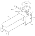
도 1은 본 발명의 일 실시예에 따른 운동기구의 사시도이다.1 is a perspective view of an exercise device according to an embodiment of the present invention.
본 발명의 일 실시예에 따른 운동기구에는 무게추가 수용되는 벤치(100), 상기 벤치(100)의 상하로 이동 가능한 복수의 연결봉(220)들, 상기 연결봉(220)들에 연결되어 있는 손잡이지지대(300), 그리고 상기 손잡이지지대(300) 내부를 따라 이동 가능한 손잡이(400)가 포함된다.In the exercise device according to an embodiment of the present invention, a weight support is provided in the
상기 벤치(100)에는 제1벤치(110)와 제2벤치(120)가 포함된다.The
제1벤치(110)의 상면에는 사용자의 보호를 위해 쿠션 등의 완충부재가 부착될 수 있다.A cushioning member such as a cushion may be attached to the upper surface of the
또한, 제1벤치(110)의 하면에는 제1벤치(110)의 이동을 용이하게 하는 바퀴(115)가 장착되어 있다. 따라서 운동을 하지 아니할 때에는 상기 제1벤치(110)를 다른 장소로 용이하게 옮길 수 있다. 이때, 다른 장소로 옮겨진 제1벤치(110)는 장식장 등으로 활용될 수 있다.In addition, the lower surface of the
그리고 도시하지는 아니하였으나, 바퀴(115)가 회전하지 아니하도록 고정하여, 운동을 할 때는 제1벤치(110)가 이동하지 아니하도록 할 수 있다.Although not shown, the
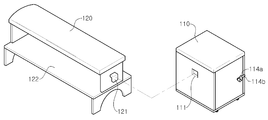
도 2에는 제1벤치(110)의 사시도이다.2 is a perspective view of the
제1벤치(110)는 내부가 빈 케이스 형상으로, 상측에 구멍이 형성되어 있다. 그리고 제1벤치(110)의 일면은 개방되어 있고, 내부에는 리프터(210)와 복수의 무게추(600)가 수용되어 있다.The
종래 무게추(600)를 벤치 측면에 보관하는 것과 달리, 무게추(600)를 제1벤치(110) 내부에 보관함으로써, 공간 활용도를 증가시킬 수 있다. 또한, 손잡이에 바벨 등을 끼워서 운동하는 해머벤치와 달리 무게추(600)를 제1벤치(110) 내부에 보관함으로써, 손잡이에 바벨을 끼우기 위하여 바벨을 이동하는 과정에서 바벨을 떨어뜨려서 발생하는 사고가 방지된다. 또한, 바벨을 별도로 보관하여야 하는 번거로움이 줄어든다.Unlike storing the
무게추(600)는 그 길이방향을 따라 일면의 양측에 관통핀(700)이 삽입 가능한 관통홀(610)이 형성되어 있다. The
복수의 무게추(600) 각각은 동일 중량일 수 있다. 이 경우, 무게추(600)의 개수에 따라 전체적인 무게추(600)의 중량이 무게추(600)의 개수에 비례하여 들어 올리고자 하는 중량을 용이하게 조절될 수 있다.Each of the plurality of
리프터(210)는 후술되는 연결봉(220)에 연결되어 있고, 최상층의 무게추(600) 위에 놓인다. 리프터(210)에는 관통홀(610)에 대응되어 연결홀(211)이 형성되어 있다. 연결홀(211)은 리프터(210)에서 높이를 달리하여 복수가 형성되어 있다. 이때 높이가 상이한 연결홀(211)의 간격은 무게추(600)의 두께와 동일하다. 따라서 리프터(210)가 무게추(600)위에 놓이는 경우, 연결홀(211)과 관통홀(610)은 서로 중첩된다.The
리프터(210)는 연결홀(211)에 삽입되는 관통핀(700)을 통하여 무게추(600)와 연결된다. 따라서 관통핀(700)은 연결홀(211)과 관통홀(610)에 삽입되어 리프터(210)와 무게추(600)를 연결한다.The
일례로, 두개의 무게추(600)를 들어 올리고자 하는 경우, 위에서 두번째의 연결홀(211)에 관통핀(700)을 삽입하면, 관통핀(700)에 의해 리프터(210)와 무게추(600)가 연결된다. 이와 같이, 관통핀(700)으로 무게추(600)의 개수를 조절하고, 이를 통해 들어 올리는 무게추(600)의 중량을 조절할 수 있다. For example, if you want to lift the two
제1벤치(110)의 개방된 면의 일측에는 경첩이 연결되어 있고, 상기 경첩을 통하여 제1벤치(110)에 문(113)이 연결되어 있다. 문(113)은 개방된 면의 전방으로 회동 가능하다. 또는, 문(113)이 제1벤치(110)에 힌지결합 되어, 문(113)이 제1벤치(110)의 개방된 면의 전방으로 회동할 수 있다. 상기 명시한 구성 이외에도, 문(113)이 제1벤치(110)의 개방된 면 전방으로 회동 가능하게 연결되어 있을 수 있다.A hinge is connected to one side of an open surface of the
문(113)이 제1벤치(110)에 접하여 개방된 면을 폐쇄할 때에는, 그 상태를 유지할 수 있도록, 문(113)과 제1벤치(110) 중 어느 하나에는 끼움고리(114b)가 형성되어 있고, 다른 하나에는 상기 끼움고리(114b)가 걸릴 수 있는 끼움부(114a)가 형성되어 있다.When the
문(113)이 제1벤치(110)에 접할 때에는 끼움고리(114b)를 회동하여 끼움부(114a)에 걸어, 문(113)이 닫힌 상태를 유지할 수 있다. When the
문(113)이 제1벤치(110)에 닫힌 상태가 유지되는 경우, 제1벤치(110)를 이동할 때 제1벤치(110) 내부의 무게추(600)가 외부로 떨어져 제1벤치(110) 이동자의 발이 다치는 사고가 방지될 수 있다.When the
이 외에도, 문(113)과 제1벤치(110)에는, 문(113)이 제1벤치(110)에 닫힌 상태를 유지할 수 있는 다른 부재가 형성되어 있을 수 있다.In addition, another member may be formed in the
제2벤치(120)는 사용자가 누울 수 있는 공간으로, 제1벤치(110)에 분리 가능하게 연결되어 있다. The
제2벤치(120)의 상면에는 제1벤치(110)의 상면과 같이, 사용자의 보호를 위해 쿠션 등의 완충부재가 부착될 수 있다. A buffer member such as a cushion may be attached to the upper surface of the
제2벤치(120)는 적어도 일측이 개방되어 있다. 그리고 제2벤치(120)에는 선반(122)이 형성되어 있다. 따라서 운동을 하지 아니할 때에는 제2벤치(120)의 내부 선반(122)에 물건을 전시하거나 책 등을 보관하여 장식장 또는 책장 등의 용도로 활용할 수 있다. At least one side of the
또한 선반(122)의 폭은 제2벤치(12)의 폭보다 크게 제작되어 사용자가 제2벤치에 누웠을 때 다리를 선반(122)상에 올려놓은 상태에서 운동이 가능하다.In addition, the width of the
한편, 도 3은 제1벤치(110)과 제2벤치(120)의 결합구조를 도시한 사시도이다.3 is a perspective view illustrating a coupling structure of the
제2벤치(120)에 걸림고리(121)가 형성되어 있고, 제1벤치(110)에 걸림홈(111)이 형성되어 있다. 그러나 제1벤치(110)에 걸림고리(121)가 형성되고, 제2벤치(120)에 걸림홈(111)이 형성될 수 있다.The
상기 걸림고리(121)가 걸림홈(111)에 삽입되어 제2벤치(120)와 제1벤치(110)가 분리되지 아니하도록 고정될 수 있다. 이 경우, 운동 중에 제1벤치(110)와 제2벤치(120)가 분리되어 사용자가 낙상하는 사고를 방지할 수 있다. The
또한, 제1벤치(110)와 제2벤치(120)가 분리하여, 운동하지 아니하는 때에는 제1벤치(110)와 제2벤치(120)를 분리하여 각각 보관할 수 있다. 제1벤치(110)와 제2벤치(120)를 분리하여, 이들 각각을 장식장 또는 책장 등으로 활용 가능하다. 이때, 제1벤치(110)와 제2벤치(120)를 분리하여 보관 가능하므로, 공간을 효율적으로 사용할 수 있다.In addition, when the
걸림고리(121)와 걸림홈(111) 외에도 제1벤치(110)와 제2벤치(120)에, 제1벤치(110)와 문(113)의 끼움고리(114b)과 끼움부(114a)의 부재가 형성되어 제1벤치(110)와 제2벤치(120)가 분리 가능하게 연결될 수 있다. 상기 명시한 부재 이외에도 걸림고리(121)와 걸림홈(111)은 제1벤치(110)와 제2벤치(120)가 분리 가능하게 연결될 수 있는 다른 부재로 전용될 수 있다.In addition to the
그러나 제1벤치(110)와 제2벤치(120)는 분리되지 아니하고, 일체로 형성될 수 있다. 이 경우, 사용자가 운동을 하고자 할 때마다 분리되어 있던 제1벤치와 제2벤치를 결합하여야 하는 번거로움이 방지된다.However, the
연결부(200)에는 연결봉(220)과 전술한 리프터(210)가 포함된다.The connecting portion 200 includes a connecting
연결봉(220)은 손잡이지지대(300)와 리프터(210)를 연결하는 부재이다. 연결봉(220)은 제1벤치의 구멍에 삽입되어, 제1벤치(110)의 상하로 이동 가능하다.
손잡이지지대(300)는 연결봉(220)에 연결되어 있고, 손잡이(400)의 이동을 안내한다.The
도 5에는 본 발명 운동기구의 일 실시예에 따른 사용상태도가 도시되어 있다.5 is a state diagram used in accordance with an embodiment of the exercise device of the present invention.
손잡이지지대(300)에는 서로 이격되어 있으며, 상기 손잡이(400)의 이동을 안내하는 한 쌍의 제1지지대(310)들, 상기 제1지지대(310)들에서 상기 벤치(100)의 상면에 평행하게 연결되어 있고 서로 이격되어 있는 한 쌍의 제2지지대(320)들, 그리고 상기 제2지지대(320)들에서 연장되어 있고, 상기 제2지지대(320)들을 연결하는 제3지지대(330)가 포함되어 벤치(100)에 눕는 사용자의 머리의 둘레에 데어진다. 즉, 사용자가 벤치(100)에 눕거나 벤치(100)에서 일어날 때 사용자의 이동에 간섭되지 아니한다.The
제1지지대(310)들이 서로 이격되어 있어 손잡이지지대(300) 내부에 공간이 형성되어 있으므로, 사용자가 벤치(100)에 눕거나 일어날 때, 사용자의 머리 또는 목 등이 부딪히지 아니하게 된다. Since the
도 1에는 연결봉(220)이 제2지지대(320)에 연결되어 있는 형상이 도시되어 있으나, 연결봉(220)은 제1지지대(310)에 연결될 수 있다. 1 illustrates that the connecting
손잡이(400)는 제1지지대(310) 내부에 삽입되어 제1지지대(310)를 따라 사용자의 어깨너비보다 크게 벌어지거나 좁게 모여질 수 있다. The
손잡이의 끝단부에는 미끄러짐을 방지하기 위하여 고무가 덧대어져 있다. 그러나 고무는 마찰력을 증가하여 운동 시에 손의 미끄럼을 방지할 수 있는 다른 부재로 전용될 수 있다.The tip of the handle is padded with rubber to prevent slipping. However, the rubber can be converted to another member that can increase the frictional force to prevent slipping of the hand during exercise.
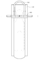
한편, 도 4에는 손잡이(400)의 와 손잡이지지대(300)의 단면도가 도시되어 있다.On the other hand, Figure 4 is a cross-sectional view of the
제1지지대(310)는 그 내측면의 둘레를 따라 일정 간격으로 복수의 홈(311)이 형성되어 있고, 손잡이(400)에는 상기 홈(311)에 접촉 가능한 탄성부(410)가 구비되어 있어, 손잡이(400)의 이동간격이 조절될 수 있다.The
탄성부(410)에는 일례로 하우징(411), 탄성부재(412), 그리고 탄성볼(413)이 포함된다.The elastic part 410 includes, for example, a
하우징(411)은 손잡이(400)의 내측에 구비되어 있다. 하우징(411) 내부에는 탄성부재(412)가 삽입되어 있고, 상기 탄성부재(412)의 일단에는 손잡이(400)의 외측을 향하여 탄성볼(413)이 연결되어 있다. 탄성볼(413)은 제1지지대의 홈(311)에 접촉하여 손잡이(400)의 위치를 고정한다. 따라서 사용자의 체격에 맞게 손잡이(400)의 간격을 조절하여 사용할 수 있다.The
손잡이(400)를 이동할 때는 이동하고자 하는 방향으로 손잡이(400)에 힘을 가하여 탄성부재(412)를 압축한다. 이때, 홈(311)에 접해있는 탄성볼(413)이 탄성부재(412)쪽으로 하강하게 되고, 손잡이(400)가 이동하게 된다. 손잡이(400)의 간격이 조절되면 탄성부재(412)의 탄성력에 의해 탄성볼(413)이 홈(311)에 걸리게 되어, 사용자가 손잡이(400)를 위아래로 움직이며 운동할 때, 손잡이(400)의 간격이 고정되게 된다.When the
또는, 도시하지는 아니하였으나, 탄성부(410)는 판스프링일 수 있다. 이때, 손잡이(400)에 손잡이(400)의 길이방향을 따라 판스프링이 부착되어 있다. 이때, 판스프링이 홈(311)에 걸리게 되어 손잡이(400)의 이동간격을 조절할 수 있다.Alternatively, although not shown, the elastic portion 410 may be a leaf spring. At this time, the leaf spring is attached to the
탄성부(410)는 명시한 부재 이외에도 손잡이지지대(300)에서 슬라이딩되는 손잡이(400)의 이동간격을 조절할 수 있는 다른 부재로 전용 가능하다.The elastic part 410 may be converted into another member capable of adjusting the moving interval of the
손잡이(400)가 원기둥 형상이어서 손잡이(400)가 손잡이지지대(300) 내부에서 회전되어도, 손잡이지지대(300) 내부의 홈(311)이 손잡이지지대(300) 내측면을 따라 형성되어 있어, 탄성볼(413)이 홈(311)에서 이탈되지 아니한다.Since the
손잡이(400)는 원기둥 형상 이외에 사각기둥 등 각이 있는 형상으로 형성될 수 있다. 이때, 손잡이(400)가 손잡이지지대(300) 내부에서 회전되지 아니한다.The
또한, 도 6에 도시되어 있는 바와 같이, 양손을 어깨너비로 벌리지 아니하고, 손잡이(400)를 제1지지대(310) 내측으로 이동하여 양손을 가슴 위에 위치하여 상체운동을 할 수도 있다.In addition, as shown in Figure 6, without having to open both hands shoulder width, the
일반적으로 양손을 어깨너비로 벌려서 운동할 때는 가슴부위 대흉근 어깨부위 삼각근 및 승모근이 발달된다. 양손을 가슴 위로 좁혀서 운동할 때는 팔에 운동효과가 있는데, 특히 팔 바깥쪽의 삼두근이 발달된다.In general, when you exercise with both hands wide shoulder width chest chest pectoralis shoulder shoulder deltoids and mitral muscles are developed. When you exercise with both hands narrowed over your chest, you have an exercise effect on your arms, especially the triceps on the outside of your arm.
따라서 본 발명은 손잡이(400)를 이동하여 하나의 운동기구로 다양한 부위의 근육운동을 할 수 있다.Therefore, the present invention can move the
제1벤치(110)의 상면에는 연결봉(220)의 이동을 안내하는 연결봉지지대(500)가 연결되어 있다. The connecting
연결봉지지대(500)는 상기 벤치(100)의 상면에 연결되어 있고, 상기 연결봉(220)의 이동을 안내하며, 그 상부면에 상기 손잡이지지대(300)가 접하여 상기 손잡이지지대의 최소하강높이를 한정한다.The connecting
이때 최소하강높이는 사용자가 벤치에 누웠을 때 등에서 가슴 높이이다. The minimum descent height is the chest height at the back when the user is lying on the bench.
운동 중에 힘이 빠져 손잡이(400)를 놓치거나, 손잡이(400)를 위로 들어 올릴 힘이 없을 때, 손잡이(400)가 사용자의 가슴 바로 위에 올려져 가슴을 짓누르게 되는 사고가 방지된다. When the force is missed during the exercise, the
또한, 연결봉(220)이 손잡이(400) 또는 제1지지대(310)에 연결되어 있지 아니한 경우, 손잡이(400)의 중심과 무게추의 이동을 위한 연결봉(220)의 중심이 일직선상에 위치하지 아니하여 연결봉(220)이 제1벤치(110)에서 수직한 방향으로 이동되지 아니할 수 있다. 이때, 연결봉지지대(500)가 제1벤치에 더 연결되어 있어, 연결봉(220)이 제1벤치(110)에서 수직방향으로 이동할 수 있도록 연결봉(220)의 이동을 안내한다.In addition, when the connecting
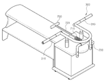
[도 7]은 본 발명의 다른 실시예를 나타낸 도면으로 기본적인 구성은 앞의 실시예와 동일하되, 벤치프레스에 의한 운동외에 다른 운동기구가 더 포함된 것에 차이가 있다.7 is a view showing another embodiment of the present invention, the basic configuration is the same as the previous embodiment, but there is a difference that other exercise equipment is further included in addition to the exercise by the bench press.
이렇게 추가된 운동기구는 크게 지지프레임(700)과 스프링(710), 연결와이어(720) 및 손잡이(730)을 포함하여 구성된다.The added exercise device is largely configured to include a
그 중 지지프레임(700)은 타 운동 시 지지대 역할을 하는 것으로, 막대를 절곡시킨 구조이고 제2벤치의 전면에 볼트 등을 통해 고정설치된다.Among them, the
그리고 스프링(710)은 타 운동 시 인장 및 수축력을 부여하는 역할을 하는 것으로, 일반적인 코일스프링 형태이고 일단부가 지지프레임에 연결된 상태로 설치된다.In addition, the
이러한 스프링에 연결되는 연결와이어(730)는 사용자의 힘을 스프링에 전달하는 역할을 하는 것으로, 일반적인 와이어 형태이고 일단부가 스프링에 연결된 상태로 설치되며 타단부에는 손잡이(740)가 설치된다.The
참고로 연결와이어를 생략하고 손잡이를 스프링에 직접 연결시킬 수도 있다.For reference, you can omit the connection wire and connect the handle directly to the spring.
이러한 구조에 의해 사용자는 벤치에 걸터앉은 상태에서 양손으로 손잡이를 잡고 사용자 쪽으로 잡아당기면 코일스프링의 자체 탄성력에 의해 운동효과가 발휘된다.
By this structure, the user grasps the handle with both hands while sitting on the bench and pulls it toward the user to exert the movement effect by the elastic force of the coil spring.
이상에서 본 발명의 바람직한 실시예들에 대하여 상세하게 설명하였지만 본 발명의 권리범위는 이에 한정되는 것은 아니고 다음의 청구범위에서 정의하고 있는 본 발명의 기본 개념을 이용한 당업자의 여러 변형 및 개량 형태 또한 본 발명의 권리범위에 속하는 것이다.While the present invention has been particularly shown and described with reference to exemplary embodiments thereof, it is to be understood that the invention is not limited to the disclosed exemplary embodiments, And falls within the scope of the invention.
100 : 벤치
110 : 제1벤치 111 : 걸림홈
112 : 구멍 113 : 문
114a : 끼움부 114b : 끼움고리
115 : 바퀴
120 : 제2벤치
121 : 걸림고리 122 : 선반
200 : 연결부
210 : 리프터 211 : 연결홀
220 : 연결봉
300 : 손잡이지지대
310 : 제1지지대 311 : 홈
320 : 제2지지대 330 : 제3지지대
400 : 손잡이
410 : 탄성부 411 : 하우징
412 : 탄성부재 413 : 탄성볼
500 : 연결봉지지대
600 : 무게추
610 : 관통홀
700 : 관통핀100: bench
110: first bench 111: hanging groove
112: hole 113: door
114a:
115: Wheels
120: second bench
121: hook ring 122: shelf
200: connection
210: lifter 211: connecting hole
220: connecting rod
300: handle support
310: first support 311: groove
320: second support 330: third support
400: handle
410: elastic portion 411: housing
412
500: connecting rod support
600: weight
610: through hole
700: through pin
Claims (10)
일부가 상기 구멍에 삽입되어 상측은 상기 벤치 외부로 돌출되어 있고 하부는 벤치 아래에 위치하고 있는 연결봉,
상기 연결봉의 상측에 연결되어 있는 손잡이,
상기 연결봉의 하부에 연결되어 있는 적어도 하나 이상의 무게추,
를 포함하고 상기 연결봉이 승강되면 상기 무게추도 함께 승강되는
운동기구,Benches with holes in the upper surface,
A connecting rod having a portion inserted into the hole so that the upper portion protrudes out of the bench and the lower portion is located under the bench;
A handle connected to an upper side of the connecting rod,
At least one weight connected to the lower portion of the connecting rod,
Includes and when the connecting rod is elevated is also lifted with the weight
Fitness equipment,
상기 무게추는 복수개가 상하 적층되어 있는 구조로 이루어져 있는
운동기구.In claim 1,
The weight is made up of a structure in which a plurality of weights are stacked up and down
Fitness equipment.
일부가 상기 각 구멍에 삽입되어 상측은 상기 벤치 외부로 돌출되어 있고 하부는 벤치 아래에 위치하고 있으며 상하 승강이 가능한 연결봉,
상기 연결봉에 연결되어 있는 무게추,
상기 각 연결봉에 연결되어 있는 손잡이 지지대,
상기 각 손잡이지지대에 지면과 수평 상태로 관통설치되어 양방향으로 슬라이딩 가능하도록 설치되어 있는 손잡이
를 포함하는 운동기구.Benches with holes on both sides of the top surface,
A connecting rod is inserted into each of the holes so that the upper part protrudes out of the bench and the lower part is located under the bench and is capable of lifting up and down,
Weight weight is connected to the connecting rod,
A handle support connected to each connecting rod,
Handles are installed to be slid in both directions by penetrating horizontally to the ground on each of the handle support
Exercise equipment comprising a.
상기 손잡이지지대에는
서로 이격되어 있으며, 상기 손잡이의 이동을 안내하는 한 쌍의 제1지지대들,
상기 제1지지대들에서 상기 벤치의 상면에 평행하게 연결되어 있고 서로 이격되어 있는 한 쌍의 제2지지대들, 그리고
상기 제2지지대들에서 연장되어 있고, 상기 제2지지대들을 연결하는 제3지지대가 포함되어
상기 손잡이지지대가 벤치에 눕는 사용자 머리의 둘레에 둘러지는 운동기구.4. The method of claim 3,
The handle support is
A pair of first supports spaced apart from each other to guide movement of the handle;
A pair of second supports connected in parallel with the upper surface of the bench at the first supports and spaced apart from each other, and
A third support extending from the second supports and connecting the second supports
Exercise equipment is wrapped around the user's head lying on the bench the handle support.
상기 무게추는 상기 벤치 내부에 복수가 적층되어 있고,
각 상기 무게추에는
양 측면에 그 길이방향을 따라 복수의 관통홀이 형성되어 있고,
최상층의 상기 무게추 위에 있고, 상기 관통홀에 대응되어 연결홀이 형성되어 있으며 상기 연결봉에 연결되어 있는 리프터
를 포함하는 운동기구.3. The method according to claim 2 or 3,
The weight is stacked in plurality inside the bench,
On each of these weights
A plurality of through holes are formed at both sides along the longitudinal direction thereof.
The lifter is on the weight of the uppermost layer, the connection hole is formed corresponding to the through hole and connected to the connecting rod
Exercise equipment comprising a.
상기 손잡이지지대는 내측면에 복수의 홈이 형성되어 있고,
상기 손잡이에는 상기 홈에 접촉 가능한 탄성부가 구비되어 있는 운동기구.4. The method of claim 3,
The handle support is formed with a plurality of grooves on the inner side,
The handle is provided with an elastic portion capable of contacting the groove.
상기 벤치는
상기 구멍이 형성되어 있는 제1벤치, 그리고
상기 제1벤치에서 분리 가능하게 연결되어 있는 제2벤치
를 포함하는 운동기구.The method according to claim 1 or 3,
The bench is
A first bench in which the hole is formed, and
A second bench detachably connected to the first bench
Exercise equipment comprising a.
상기 벤치의 상면에 연결되어 있고, 상기 연결봉과 연결되어 상기 연결봉의 승강을 안내하는 연결봉지지대가 더 포함되는 운동기구.The method according to claim 1 or 3,
Is connected to the upper surface of the bench, the exercise device is connected to the connecting rod further comprises a connecting rod support for guiding the lifting of the connecting rod.
상기 제1벤치 또는 상기 제2벤치 중 어느 하나에는 걸림고리가 형성되어 있고, 다른 하나에는 상기 걸림고리가 걸릴 수 있는 걸림홈이 형성되어 있는 운동기구.In claim 7,
Any one of the first bench or the second bench has a hook is formed, the other is the exercise device is formed with a locking groove that the hook can be caught.
상기 제2벤치는
적어도 일측이 개방되어 있고, 내부에 선반이 형성되어 있는 운동기구.
In claim 7,
The second bench
At least one side is open, the exercise equipment is formed inside the shelf.
Priority Applications (1)
| Application Number | Priority Date | Filing Date | Title |
|---|---|---|---|
| KR1020110039770A KR101247562B1 (en) | 2011-04-27 | 2011-04-27 | Healthmachine |
Applications Claiming Priority (1)
| Application Number | Priority Date | Filing Date | Title |
|---|---|---|---|
| KR1020110039770A KR101247562B1 (en) | 2011-04-27 | 2011-04-27 | Healthmachine |
Publications (2)
| Publication Number | Publication Date |
|---|---|
| KR20120121774A true KR20120121774A (en) | 2012-11-06 |
| KR101247562B1 KR101247562B1 (en) | 2013-03-25 |
Family
ID=47508174
Family Applications (1)
| Application Number | Title | Priority Date | Filing Date |
|---|---|---|---|
| KR1020110039770A KR101247562B1 (en) | 2011-04-27 | 2011-04-27 | Healthmachine |
Country Status (1)
| Country | Link |
|---|---|
| KR (1) | KR101247562B1 (en) |
Cited By (2)
| Publication number | Priority date | Publication date | Assignee | Title |
|---|---|---|---|---|
| KR101349608B1 (en) * | 2013-02-14 | 2014-01-09 | 순천향대학교 산학협력단 | Muscle strengthening apparatus for occupational therapy |
| KR102044974B1 (en) * | 2018-05-08 | 2019-11-14 | 박기찬 | Field bench press to control weight |
Families Citing this family (1)
| Publication number | Priority date | Publication date | Assignee | Title |
|---|---|---|---|---|
| KR101421932B1 (en) | 2013-01-28 | 2014-07-23 | 현대체육산업(주) | Platform for Weight lifting |
Family Cites Families (3)
| Publication number | Priority date | Publication date | Assignee | Title |
|---|---|---|---|---|
| GB9700384D0 (en) * | 1997-01-10 | 1997-02-26 | Morton Lee R | Exercise apparatus |
| KR100728821B1 (en) | 2005-09-28 | 2007-06-14 | (주)소프트인하드 | a health apparatus |
| KR200407771Y1 (en) | 2005-11-21 | 2006-02-03 | 전현렬 | Health machine using elasticity of spring |
-
2011
- 2011-04-27 KR KR1020110039770A patent/KR101247562B1/en not_active IP Right Cessation
Cited By (2)
| Publication number | Priority date | Publication date | Assignee | Title |
|---|---|---|---|---|
| KR101349608B1 (en) * | 2013-02-14 | 2014-01-09 | 순천향대학교 산학협력단 | Muscle strengthening apparatus for occupational therapy |
| KR102044974B1 (en) * | 2018-05-08 | 2019-11-14 | 박기찬 | Field bench press to control weight |
Also Published As
| Publication number | Publication date |
|---|---|
| KR101247562B1 (en) | 2013-03-25 |
Similar Documents
| Publication | Publication Date | Title |
|---|---|---|
| US9028381B2 (en) | Door-mounted fitness device with removable pulley members | |
| TWI552787B (en) | Multifunctional leg training device | |
| US4286782A (en) | Multi-purpose exercise enhancing device | |
| US9067100B2 (en) | Dual resistance exercise apparatus | |
| US20140080685A1 (en) | Multifunctional exercise machines | |
| US20100216610A1 (en) | Free weight training simulation apparatus | |
| US9199111B2 (en) | Exercise apparatus | |
| US20110224057A1 (en) | Universal fitness machine | |
| US20050209054A1 (en) | Exercise device and system | |
| RU176951U1 (en) | Multifunction muscle trainer | |
| KR101793904B1 (en) | Multifunction fitness equipment | |
| US9586075B2 (en) | Exercise device for performing dips | |
| KR101247562B1 (en) | Healthmachine | |
| US5487712A (en) | Method of exercising using a pivoting exercise apparatus | |
| US20190247713A1 (en) | Machine for Performance of Front Squat Exercises | |
| CN206852991U (en) | A kind of exercise chair | |
| KR101986179B1 (en) | outdoor Muscular Strength Measuring Instrument | |
| US20140038797A1 (en) | Tilting exercise device | |
| US10780317B1 (en) | Exercise apparatus | |
| US9895574B2 (en) | Exercise device for strengthening of abdominal muscles | |
| KR102115695B1 (en) | weight machine | |
| WO2023160134A1 (en) | Fitness device | |
| CN109011343B (en) | Muscle sports training ware | |
| WO2015182190A1 (en) | Barbell and bench press device employing barbell | |
| KR102090777B1 (en) | Multipurpose Exercise Machine |
Legal Events
| Date | Code | Title | Description |
|---|---|---|---|
| A201 | Request for examination | ||
| E902 | Notification of reason for refusal | ||
| E701 | Decision to grant or registration of patent right | ||
| GRNT | Written decision to grant | ||
| LAPS | Lapse due to unpaid annual fee |