KR20120121663A - Guide frame for combining segment girder and assembling method thereof - Google Patents
Guide frame for combining segment girder and assembling method thereof Download PDFInfo
- Publication number
- KR20120121663A KR20120121663A KR1020110039598A KR20110039598A KR20120121663A KR 20120121663 A KR20120121663 A KR 20120121663A KR 1020110039598 A KR1020110039598 A KR 1020110039598A KR 20110039598 A KR20110039598 A KR 20110039598A KR 20120121663 A KR20120121663 A KR 20120121663A
- Authority
- KR
- South Korea
- Prior art keywords
- segment girder
- assembling
- guide frame
- adjustment
- support
- Prior art date
- Legal status (The legal status is an assumption and is not a legal conclusion. Google has not performed a legal analysis and makes no representation as to the accuracy of the status listed.)
- Granted
Links
Images


Classifications
-
- E—FIXED CONSTRUCTIONS
- E01—CONSTRUCTION OF ROADS, RAILWAYS, OR BRIDGES
- E01D—CONSTRUCTION OF BRIDGES, ELEVATED ROADWAYS OR VIADUCTS; ASSEMBLY OF BRIDGES
- E01D2/00—Bridges characterised by the cross-section of their bearing spanning structure
-
- E—FIXED CONSTRUCTIONS
- E01—CONSTRUCTION OF ROADS, RAILWAYS, OR BRIDGES
- E01D—CONSTRUCTION OF BRIDGES, ELEVATED ROADWAYS OR VIADUCTS; ASSEMBLY OF BRIDGES
- E01D19/00—Structural or constructional details of bridges
-
- E—FIXED CONSTRUCTIONS
- E01—CONSTRUCTION OF ROADS, RAILWAYS, OR BRIDGES
- E01D—CONSTRUCTION OF BRIDGES, ELEVATED ROADWAYS OR VIADUCTS; ASSEMBLY OF BRIDGES
- E01D21/00—Methods or apparatus specially adapted for erecting or assembling bridges
Landscapes
- Engineering & Computer Science (AREA)
- Architecture (AREA)
- Civil Engineering (AREA)
- Structural Engineering (AREA)
- Lining And Supports For Tunnels (AREA)
- Bridges Or Land Bridges (AREA)
Abstract
본 발명은 세그먼트 거더 조립용 가이드 프레임에 관한 것으로서, 서로 이격되게 배치되고, 사이 공간에 받침대가 위치하는 한 쌍의 받침부재와, 받침부재와 결합되고, 세그먼트 거더의 일측을 가이드하는 제1조절부재와, 제1조절부재와 이격되게 배치되도록 받침부재와 결합되고, 세그먼트 거더의 타측을 가이드하는 제2조절부재를 포함하는 것을 특징으로 한다.The present invention relates to a guide frame for assembling a segment girder, which is spaced apart from each other, a pair of supporting members having a pedestal located in an interspace, and a first adjusting member coupled to the supporting member and guiding one side of the segment girder. And a second adjusting member coupled to the supporting member so as to be spaced apart from the first adjusting member and guiding the other side of the segment girder.

Description
본 발명은 가이드 프레임 및 그 조립 방법에 관한 것으로서, 더욱 상세하게는 조립 및 설치에 따른 비용 및 시간을 절감할 수 있고, 세그먼트 거더 간 조립의 정확성을 확보할 수 있는 세그먼트 거더 조립용 가이드 프레임 및 그 조립 방법에 관한 것이다.
The present invention relates to a guide frame and a method for assembling the same, and more particularly, a guide frame for assembling a segment girder, which can reduce the cost and time according to the assembly and installation, and can ensure the accuracy of assembling between segment girders, and the same. It is related to an assembly method.
최근 거더(Girder)의 장경간화, 공기단축, 공사비 절감 등이 요구되고 관련 기술이 발달하면서 거더를 세그먼트(Segment)화하여 공장제작 후 현장으로 운반하여 조립하는 공법들이 다수 개발되고 있다. Recently, the girder is required to be long-sized, shorten the air, and reduce the construction cost. With the development of related technologies, a number of methods are developed to segment the girder and transport it to the site after assembling the plant.
따라서 현장에서의 거더의 조립은 거더의 제작과 운반, 가설과 더불어 중요 공정으로 자리매김하고 있는 실정이다. Therefore, the assembly of girders in the field has been established as an important process along with the manufacture, transportation, and construction of girders.
세그먼트 거더의 조립 시 세그먼트 거더의 접합면이 일치하지 않으면 긴장력에 의해 과도한 횡변위나 처짐 등이 발생할 수 있어 거더의 불량을 초래할 수 있으므로, 세그먼트 거더는 접합면이 정확하게 일치되도록 조립되어야 한다. If the joints of the segment girders do not coincide with each other when the segment girders are assembled, excessive lateral displacement or deflection may occur due to the tension force, which may cause the failure of the girders.
상기한 기술구성은 본 발명의 이해를 돕기 위한 배경기술로서, 본 발명이 속하는 기술분야에서 널리 알려진 종래기술을 의미하는 것은 아니다.
The technical structure described above is a background technique for assisting the understanding of the present invention, and does not mean the prior art widely known in the technical field to which the present invention belongs.
종래에는 레일 위를 이동하는 대차를 이용하여 세그먼트 거더를 이동시키면서 조립하였으나, 레일과 대차를 설치하는데 있어 과도한 비용 및 시간이 드는 문제점이 있다. Conventionally, assembling while moving the segment girder using a bogie moving on the rail, there is a problem that excessive cost and time for installing the rail and bogie.
따라서 이를 개선할 필요성이 요청된다.Therefore, there is a need for improvement.
본 발명은 상기와 같은 문제점들을 개선하기 위해 안출된 것으로서, 조립 및 설치에 따른 비용 및 시간을 절감할 수 있고, 세그먼트 거더 간 조립의 정확성을 확보할 수 있는 세그먼트 거더 조립용 가이드 프레임 및 그 조립 방법을 제공하는데 그 목적이 있다.
The present invention has been made to improve the above problems, and can reduce the cost and time according to the assembly and installation, the guide frame for assembly of the segment girder and the assembly method that can ensure the accuracy of the assembly between the segment girder The purpose is to provide.
본 발명에 따른 세그먼트 거더 조립용 가이드 프레임은: 서로 이격되게 배치되고, 사이 공간에 받침대가 위치하는 한 쌍의 받침부재; 상기 받침부재와 결합되고, 세그먼트 거더의 일측을 가이드하는 제1조절부재; 및 상기 제1조절부재와 이격되게 배치되도록 상기 받침부재와 결합되고, 상기 세그먼트 거더의 타측을 가이드하는 제2조절부재를 포함한다.The guide frame for assembling the segment girder according to the present invention includes: a pair of supporting members disposed to be spaced apart from each other and having a pedestal located in a space therebetween; A first adjusting member coupled to the supporting member and guiding one side of the segment girder; And a second adjusting member coupled to the supporting member so as to be spaced apart from the first adjusting member and guiding the other side of the segment girder.
바람직하게는, 상기 제1조절부재는 상기 세그먼트 거더의 폭에 따라 상기 제2조절부재와의 이격 거리가 조절된다.Preferably, the first adjustment member is adjusted to the separation distance with the second adjustment member according to the width of the segment girder.
더 바람직하게는, 상기 받침부재에는 일정 간격으로 복수의 받침홀부가 구비되고, 상기 제1조절부재는 상기 받침홀부와의 나사 결합을 통해 상기 받침부재와 결합된다.More preferably, the support member is provided with a plurality of support hole portions at predetermined intervals, and the first adjustment member is coupled to the support member through a screw coupling with the support hole portion.
더 바람직하게는, 상기 받침부재에는 길이 방향으로 받침눈금이 구비된다.More preferably, the support member is provided with a support scale in the longitudinal direction.
더 바람직하게는, 상기 제1조절부재에는 상기 나사가 관통하는 제1조절홀부가 일정 간격으로 복수개 구비된다.More preferably, the first adjusting member is provided with a plurality of first adjusting hole portions through which the screw passes at regular intervals.
더 바람직하게는, 상기 제1조절부재에는 상기 제1조절홀부와 동일한 방향으로 제1조절눈금이 구비된다.More preferably, the first adjustment member is provided with a first adjustment scale in the same direction as the first adjustment hole.
바람직하게는, 상기 제2조절부재는 상기 세그먼트 거더의 폭에 따라 상기 제1조절부재와의 이격 거리가 조절된다.Preferably, the second adjustment member is adjusted to the separation distance with the first adjustment member according to the width of the segment girder.
더 바람직하게는, 상기 받침부재에는 일정 간격으로 복수의 받침홀부가 구비되고, 상기 제2조절부재는 상기 받침홀부와의 나사 결합을 통해 상기 받침부재와 결합된다. More preferably, the supporting member is provided with a plurality of supporting hole portions at predetermined intervals, and the second adjusting member is coupled to the supporting member through screwing with the supporting hole portion.
더 바람직하게는, 상기 받침부재에는 길이 방향으로 받침눈금이 구비된다.More preferably, the support member is provided with a support scale in the longitudinal direction.
더 바람직하게는, 상기 제2조절부재에는 상기 나사가 관통하는 제2조절홀부가 일정 간격으로 복수개 구비된다.More preferably, the second adjusting member is provided with a plurality of second adjusting hole portions through which the screw passes at regular intervals.
더 바람직하게는, 상기 제2조절부재에는 상기 제2조절홀부와 동일한 방향으로 제2조절눈금이 구비된다.More preferably, the second adjustment member is provided with a second adjustment scale in the same direction as the second adjustment hole.
바람직하게는, 상기 받침부재는 L형강으로 구성되고, 상기 한 쌍의 받침부재는 ┓┏ 형상으로 대면되도록 배치된다. Preferably, the supporting member is made of L-shaped steel, and the pair of supporting members is disposed to face in a ┓┏ shape.
더 바람직하게는, 상기 제1조절부재와 상기 제2조절부재는 L형강으로 구성되고, 상기 제1조절부재와 상기 제2조절부재는 ┛┗ 형상으로 대면되도록 배치된다.More preferably, the first adjusting member and the second adjusting member are made of L-shaped steel, and the first adjusting member and the second adjusting member are disposed to face each other in a ┛┗ shape.
바람직하게는, 상기 한 쌍의 받침부재는 2조(組)로 이루어진다.Preferably, the pair of supporting members is composed of two sets.
본 발명에 따른 세그먼트 거더 조립용 가이드 프레임의 조립 방법은: 서로 이격되게 한 쌍의 받침부재를 배치하는 단계; 상기 받침부재에 세그먼트 거더의 일측을 가이드하는 제1조절부재를 결합하는 단계; 및 상기 받침부재에 상기 세그먼트 거더의 타측을 가이드하는 제2조절부재를 상기 제1조절부재와 이격되게 결합하는 단계를 포함한다.A method of assembling a guide frame for assembling a segment girder according to the present invention includes: arranging a pair of supporting members spaced apart from each other; Coupling a first adjustment member to guide one side of the segment girder to the support member; And coupling a second adjusting member guiding the other side of the segment girder to the supporting member to be spaced apart from the first adjusting member.
바람직하게는, 상기 한 쌍의 받침부재 사이에 받침대를 위치시키는 단계를 더 포함한다.
Preferably, the method further comprises positioning a pedestal between the pair of supporting members.
본 발명에 따르면, 조립 및 설치에 따른 비용 및 시간을 절감할 수 있고, 세그먼트 거더 간 조립의 정확성을 확보할 수 있다. According to the present invention, it is possible to reduce the cost and time according to the assembly and installation, and to ensure the accuracy of the assembly between the segment girders.
또한 본 발명에 따르면, 제2조절부재를 통해 제1조절부재와의 이격 거리를 조절할 수 있으므로, 하나의 가이드 프레임으로 다양한 폭의 세그먼트 거더의 이동을 가이드할 수 있다.In addition, according to the present invention, since the separation distance with the first adjusting member can be adjusted through the second adjusting member, it is possible to guide the movement of the segment girder of various widths with one guide frame.
또한 본 발명에 따르면, 세그먼트 거더는 제2조절부재와 제1조절부재에 의해 가이드되면서 이동되므로, 분절된 세그먼트 거더 사이의 결합의 정확성이 향상된다.
In addition, according to the present invention, since the segment girder is moved while being guided by the second adjusting member and the first adjusting member, the accuracy of the coupling between the segmented segment girder is improved.
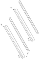
도 1은 본 발명의 일 실시예에 따른 세그먼트 거더 조립용 가이드 프레임의 받침부재가 배치된 상태를 나타낸 사시도이다.
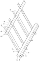
도 2는 본 발명의 일 실시예에 따른 세그먼트 거더 조립용 가이드 프레임의 제1조절부재와 제2조절부재가 받침부재에 결합된 상태를 나타낸 사시도이다.
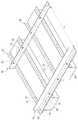
도 3은 도 2에 비해 제2조절부재가 제1조절부재측으로 이동되어 받침부재에 결합된 상태를 나타낸 사시도이다.
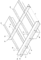
도 4는 본 발명의 일 실시예에 따른 세그먼트 거더 조립용 가이드 프레임의 받침부재 사이에 받침대가 위치된 상태를 나타낸 사시도이다.
도 5는 도 4에 비해 제2조절부재가 제1조절부재측으로 이동되어 받침부재에 결합된 상태를 나타낸 사시도이다.
도 6은 본 발명의 일 실시예에 따른 세그먼트 거더 조립용 가이드 프레임에 의해 세그먼트 거더가 조립되는 제1상태를 나타낸 측면도이다.
도 7은 도 6의 부분 확대도이다.
도 8은 본 발명의 일 실시예에 따른 세그먼트 거더 조립용 가이드 프레임에 의해 세그먼트 거더가 조립되는 상태를 나타낸 정면도이다.
도 9는 본 발명의 일 실시예에 따른 세그먼트 거더 조립용 가이드 프레임에 의해 세그먼트 거더가 조립되는 제2상태를 나타낸 측면도이다. 1 is a perspective view showing a state in which the supporting member of the guide frame for assembling the segment girder according to an embodiment of the present invention is disposed.
Figure 2 is a perspective view showing a state in which the first control member and the second control member of the guide frame for assembling the segment girder according to an embodiment of the present invention is coupled to the support member.
3 is a perspective view showing a state in which the second adjusting member is moved to the first adjusting member side and coupled to the supporting member compared to FIG. 2.
Figure 4 is a perspective view showing a state in which the pedestal is positioned between the supporting members of the guide frame for assembly of the segment girder according to an embodiment of the present invention.
5 is a perspective view showing a state in which the second adjusting member is moved to the first adjusting member side and coupled to the supporting member, compared to FIG. 4.
6 is a side view illustrating a first state in which a segment girder is assembled by a guide frame for assembling segment girder according to an embodiment of the present invention.
7 is a partial enlarged view of Fig.
8 is a front view showing a state in which the segment girder is assembled by the guide frame for assembly of the segment girder according to an embodiment of the present invention.
9 is a side view illustrating a second state in which the segment girder is assembled by the guide frame for assembling the segment girder according to the exemplary embodiment of the present invention.
이하 첨부된 도면들을 참조하여 본 발명에 따른 세그먼트 거더 조립용 가이드 프레임 및 그 조립 방법의 일 실시예를 설명한다. 이러한 과정에서 도면에 도시된 선들의 두께나 구성요소의 크기 등은 설명의 명료성과 편의상 과장되게 도시되어 있을 수 있다.Hereinafter, a guide frame for assembling a segment girder and an assembly method thereof according to the present invention will be described with reference to the accompanying drawings. In this process, the thicknesses of the lines and the sizes of the components shown in the drawings may be exaggerated for clarity and convenience of explanation.
또한 후술되는 용어들은 본 발명에서의 기능을 고려하여 정의된 용어들로써 이는 사용자, 운용자의 의도 또는 관례에 따라 달라질 수 있다. 그러므로 이러한 용어들에 대한 정의는 본 명세서 전반에 걸친 내용을 토대로 내려져야 할 것이다.
Further, terms to be described below are defined in consideration of the functions of the present invention, which may vary according to the intention or custom of the user, the operator. Therefore, the definitions of these terms should be made based on the contents throughout the specification.
도 1은 본 발명의 일 실시예에 따른 세그먼트 거더 조립용 가이드 프레임의 받침부재가 배치된 상태를 나타낸 사시도이고, 도 2는 본 발명의 일 실시예에 따른 세그먼트 거더 조립용 가이드 프레임의 제1조절부재와 제2조절부재가 받침부재에 결합된 상태를 나타낸 사시도이며, 도 3은 도 2에 비해 제2조절부재가 제1조절부재측으로 이동되어 받침부재에 결합된 상태를 나타낸 사시도이다. 도 4는 본 발명의 일 실시예에 따른 세그먼트 거더 조립용 가이드 프레임의 받침부재 사이에 받침대가 위치된 상태를 나타낸 사시도이고, 도 5는 도 4에 비해 제2조절부재가 제1조절부재측으로 이동되어 받침부재에 결합된 상태를 나타낸 사시도이다. 도 6은 본 발명의 일 실시예에 따른 세그먼트 거더 조립용 가이드 프레임에 의해 세그먼트 거더가 조립되는 제1상태를 나타낸 측면도이고, 도 7은 도 6의 부분 확대도이며, 도 8은 본 발명의 일 실시예에 따른 세그먼트 거더 조립용 가이드 프레임에 의해 세그먼트 거더가 조립되는 상태를 나타낸 정면도이다. 도 9는 본 발명의 일 실시예에 따른 세그먼트 거더 조립용 가이드 프레임에 의해 세그먼트 거더가 조립되는 제2상태를 나타낸 측면도
1 is a perspective view showing a state in which the supporting member of the guide frame for assembling the segment girder according to an embodiment of the present invention, Figure 2 is a first adjustment of the guide frame for assembling the segment girder according to an embodiment of the
도 1 내지 도 5를 참조하면, 본 발명의 일 실시예에 따른 세그먼트 거더 조립용 가이드 프레임은 받침부재(10), 제1조절부재(20), 제2조절부재(30)를 포함한다.1 to 5, the guide frame for assembling the segment girder according to the exemplary embodiment of the present invention includes a supporting
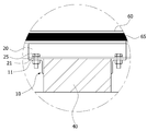
받침부재(10)는 서로 이격되게 배치되는 한 쌍의 L형강으로 이루어진다. 받침부재(10)의 이격 거리(W)는 받침대(40)의 폭과 일치되도록 한다. 이로써 받침부재(10)의 사이 공간에 위치되는 받침대(40)와 받침부재(10) 사이의 유격 발생을 최소화할 수 있다. The supporting
한 쌍의 받침부재(10)는 ┓┏ 형상으로 대면되도록 배치된다. 즉, 한 쌍의 받침부재(10)는 ┓형상으로 배치되는 받침부재(10)와, ┏ 형상으로 배치되는 받침부재(10)로 구성되며, ┓형상으로 배치되는 받침부재(10)와 ┏ 형상으로 배치되는 받침부재(10) 사이에 받침대(40)가 위치하게 된다. The pair of supporting
받침부재(10)의 상면판(부호 생략)에는 일정 간격으로 복수의 받침홀부(11)가 구비된다. 받침홀부(11)를 통해 받침부재(10)는 제1조절부재(20) 및 제2조절부재(30)와 나사 결합된다. The upper plate (not shown) of the
제1조절부재(20)는 받침부재(10)와 결합된다. 제1조절부재(20)는 받침부재(10)의 상면판에 형성되는 받침홀부(11)에 나사(25)가 결합됨에 의해 받침부재(10)와 결합된다. 제1조절부재(20)에는 나사(25)가 관통되는 제1조절홀부(21)가 구비된다(도 7 참조). The
제1조절부재(20)는 세그먼트 거더(50)의 좌측(도 8 기준)을 가이드한다. 제1조절부재(20)는 L형강으로 구성되고, 받침부재(10)의 상면판에 ┛형상으로 배치된다. 즉, 제1조절부재(20)의 하면판(부호 생략)은 받침부재(10)의 상면판과 나사 결합되고, 제1조절부재(20)의 측면판(부호 생략)은 세그먼트 거더(50)의 좌측과 맞닿는다. 이로써 제1조절부재(20)의 측면판은 세그먼트 거더(50)의 이동 시 세그먼트 거더(50)의 좌측을 가이드한다. The first adjusting
제2조절부재(30)는 받침부재(10)와 결합된다. 제2조절부재(30)는 받침부재(10)의 상면판에 형성되는 받침홀부(11)에 나사(35)가 결합됨에 의해 받침부재(10)와 결합된다. 제2조절부재(30)에는 나사(35)가 관통되는 제2조절홀부(31)가 구비된다The
제2조절부재(30)는 제1조절부재(20)와 이격되게 배치된다. 제1조절부재(20)와 제2조절부재(30)의 이격 거리(L1, L2)는 세그먼트 거더(50)의 폭과 일치되도록 한다. The
제2조절부재(30)는 세그먼트 거더(50)의 우측(도 8 기준)을 가이드한다. 제2조절부재(30)는 L형강으로 구성되고, 받침부재(10)의 상면판에 ┗ 형상으로 배치된다. 즉, 제2조절부재(30)의 하면판(부호 생략)은 받침부재(10)의 상면판과 나사 결합되고, 제2조절부재(30)의 측면판(부호 생략)은 세그먼트 거더(50)의 우측과 맞닿는다. 이로써 제2조절부재(30)의 측면판은 세그먼트 거더(50)의 이동 시 세그먼트 거더(50)의 우측을 가이드한다. The
이와 같이 세그먼트 거더(50)의 이동 시 제1조절부재(20)와 제2조절부재(30)가 각각 세그먼트 거더(50)의 좌측과 우측을 가이드하므로, 세그먼트 거더(50)의 조립 정확도는 향상된다. As such, when the
제2조절부재(30)는 제1조절부재(20)와의 이격 거리를 조절할 수 있다. 이로써 세그먼트 거더(50)의 폭이 변경되는 경우 가이드 프레임 전체를 교체할 필요 없이 제2조절부재(30)와 받침부재(10)와의 결합 위치를 변경하는 것만으로 세그먼트 거더(50)의 폭 변경에 대처할 수 있다. 즉, 복수의 가이드 프레임을 구비할 필요 없이 하나의 가이드 프레임으로도 다양한 폭의 세그먼트 거더(50)의 이동을 가이드할 수 있게 된다. The
받침부재(10)의 상면판에는 길이 방향으로 복수의 받침홀부(11)가 일정 간격으로 구비된다. 제2조절부재(30)는 나사(35)에 의해 받침홀부(11)에 나사 결합되면서 받침부재(10)와 결합되는데, 이때 세그먼트 거더(50)의 폭을 고려하여 나사(35)가 결합될 받침홀부(11)를 지정한다.The upper plate of the supporting
세그먼트 거더(50)의 폭이 L1인 경우, 도 4와 같이 제1조절부재(20)의 측면판에서 제2조절부재(30)의 측면판이 L1의 거리만큼 이격되도록 나사(35)를 통해 제2조절부재(30)를 받침부재(10)에 결합시킨다. When the width of the
세그먼트 거더(50)의 폭이 L1에서 L2로 변경된 경우, 도 5와 같이 제1조절부재(20)의 측면판에서 제2조절부재(30)의 측면판이 L2의 거리만큼 이격되도록 나사(35)를 통해 제2조절부재(30)를 받침부재(10)에 결합시킨다. When the width of the
받침부재(10)의 상면판에는 길이 방향으로 받침눈금(12)이 구비된다. 본 실시예에 따르면 받침홀부(11)가 구비되는 방향과 받침눈금(12)이 구비되는 방향은 서로 일치한다. 이로써 제1조절부재(20)의 측면판에서 제2조절부재(30)의 측면판까지의 거리를 작업자가 손쉽게 파악할 수 있게 되므로, 작업 편의성을 향상시킬 수 있다. The upper plate of the supporting
본 실시예에서는 제2조절부재(30)의 위치 변경을 통해 제1조절부재(20)와 제2조절부재(30)의 이격 거리를 조절하는 것으로 예시하였으나, 제2조절부재(30)가 고정된 상태에서 제1조절부재(20)의 위치 변경을 통해 양 부재(20, 30)의 이격 거리를 조절할 수 있음은 물론이다. 이로써 세그먼트 거더(50)의 폭이 변경되는 경우 가이드 프레임 전체를 교체할 필요 없이 제1조절부재(20)와 받침부재(10)와의 결합 위치를 변경하는 것만으로 세그먼트 거더(50)의 폭 변경에 대처할 수 있다. 즉, 복수의 가이드 프레임을 구비할 필요 없이 하나의 가이드 프레임으로도 다양한 폭의 세그먼트 거더(50)의 이동을 가이드할 수 있게 된다. In the present exemplary embodiment, the distance between the first adjusting
한 쌍의 받침부재(10)는 2조(組)로 이루어질 수 있다. 즉, 받침부재(10)는 좌측에 한 쌍, 그 우측에 한 쌍과 같이 2조로 이루어질 수 있다(도 1 참조). 이로써 긴장 전 에폭시 도포 작업을 위하여 분절된 세그먼트 거더(50)를 일정한 간격을 두고 각각 접합면이 마주보게 배치할 수 있다. The pair of supporting
1조(組)를 이루는 한 쌍의 받침부재(10)는 서로의 간격을 조절할 수 있다. 제1조절부재(20)에는 나사(25)가 관통되는 제1조절홀부(21)가 일정 간격으로 복수개가 구비되고, 제2조절부재(30)에는 나사(35)가 관통되는 제2조절홀부(31)가 일정 간격으로 복수개 구비되므로, 받침대(40)의 폭을 고려하여 나사(25, 35)가 결합될 제1조절홀부(21) 및 제2조절홀부(31)를 지정할 수 있다. 이로써 한 쌍의 받침부재(10) 사이의 간격을 현장 상황에 맞춰 조절할 수 있다.
A pair of supporting
이하 도 1 내지 도 5를 중심으로 본 발명의 일 실시예에 따른 세그먼트 거더 조립용 가이드 프레임의 조립 방법을 설명한다.Hereinafter, a method of assembling the guide frame for assembling the segment girder according to an embodiment of the present invention will be described with reference to FIGS. 1 to 5.
L형강으로 형성되는 한 쌍의 받침부재(10)를 서로 이격되게 배치한다(도 1 참조). 이때 받침부재(10)의 이격 거리(W)는 받침대(40)의 폭과 일치되도록 하고, 한 쌍의 받침부재(10)는 ┓┏ 형상으로 대면되도록 배치한다. A pair of supporting
L형강으로 형성되는 제1조절부재(20)를 받침부재(10)의 상면판에 ┛형상으로 결합한다(도 2 참조). 제1조절부재(20)는 받침부재(10)의 상면판에 형성되는 받침홀부(11)에 나사(25)가 나사 결합됨에 의해 받침부재(10)와 결합된다. 받침부재(10)에 결합된 제1조절부재(20)는 측면판을 통해 세그먼트 거더(50)의 좌측을 가이드한다(도 8 참조).The first adjusting
L형강으로 형성되는 제2조절부재(30)를 받침부재(10)의 상면판에 ┗ 형상으로 결합한다(도 2 참조). 제2조절부재(30)는 받침부재(10)의 상면판에 형성되는 받침홀부(11)에 나사(35)가 나사 결합됨에 의해 받침부재(10)와 결합된다. 제2조절부재(30)는 제1조절부재(20)와 이격되게 배치되며, 제1조절부재(20)와 제2조절부재(30)의 이격 거리(L1, L2)는 세그먼트 거더(50)의 폭과 일치되도록 한다. 받침부재(10)에 결합된 제2조절부재(30)는 측면판을 통해 세그먼트 거더(50)의 우측을 가이드한다(도 8 참조).The
받침부재(10), 제1조절부재(20), 제2조절부재(30)로 이루어지는 가이드 부재의 결합이 완료되면, 한 쌍의 받침부재(10) 사이에 받침대(40)를 위치시킨다(도 4 참조). 받침대(40)는 현장에서 쉽게 구할 수 있는 상승각 등을 이용할 수 있으며, 지면으로부터의 공간 확보와 동시에 세그먼트 거더(40)의 무게를 지탱하는 역할을 수행한다. 지면으로부터의 공간 확보는 긴장 전 에폭시 도포의 수월한 작업과 지면과의 접지면을 최소화하여 마찰 저항력을 줄이기 위함이다.
When the coupling of the guide member consisting of the
이하 도 6 내지 도 9를 중심으로 본 발명의 일 실시예에 따른 세그먼트 거더 조립용 가이드 프레임을 이용한 세그먼트 거더의 조립 방법을 설명한다.Hereinafter, a method of assembling a segment girder using a guide frame for assembling a segment girder according to an embodiment of the present invention will be described with reference to FIGS. 6 to 9.
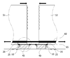
세그먼트 거더 조립용 가이드 프레임의 조립이 완료되면, 세그먼트 거더(50)를 가이드 프레임 위에 올려 놓는다. 즉, 제1세그먼트 거더(51)와 제2세그먼트 거더(52)를 받침대(40)와 받침부재(10)가 이루는 면에 올려 놓는다. When assembling of the guide frame for segment girder assembly is completed, the
제1조절부재(20)의 하면판에는 길이 방향으로 제1조절눈금(22)이 구비된다. 본 실시예에 따르면 제1조절홀부(21)가 구비되는 방향과 제1조절눈금(22)이 구비되는 방향은 서로 일치한다. 이로써 제1세그먼트 거더(51)에서 제2세그먼트 거더(52)까지의 거리를 작업자가 손쉽게 파악할 수 있게 되므로, 작업자는 현장 상황에 맞춰 제1세그먼트 거더(51)와 제2세그먼트 거더(52)의 간격을 조절할 수 있게 된다. The lower plate of the
도 6과 도 9는 제1세그먼트 거더(51)와 제2세그먼트 거더(52)가 받침부재(10)가 이루는 면에 올려 놓여진 상태를 나타낸 것으로, 이때 제1세그먼트 거더(51)와 제2세그먼트 거더(52)는 제1조절눈금(22)에 의해 의도한 간격만큼 정확하게 이격되도록 배치될 수 있다. 6 and 9 illustrate a state in which the
제2조절부재(30)의 하면판에는 길이 방향으로 제2조절눈금(32)이 구비된다. 본 실시예에 따르면 제2조절홀부(31)가 구비되는 방향과 제2조절눈금(32)이 구비되는 방향은 서로 일치한다. 이로써 제1세그먼트 거더(51)에서 제2세그먼트 거더(52)까지의 거리를 작업자가 손쉽게 파악할 수 있게 되므로, 작업자는 현장 상황에 맞춰 제1세그먼트 거더(51)와 제2세그먼트 거더(52)의 간격을 조절할 수 있게 된다. The lower plate of the
도 6과 도 9는 제1세그먼트 거더(51)와 제2세그먼트 거더(52)가 받침부재(10)가 이루는 면에 올려 놓여진 상태를 나타낸 것으로, 이때 제1세그먼트 거더(51)와 제2세그먼트 거더(52)는 제2조절눈금(32)에 의해 의도한 간격만큼 정확하게 이격되도록 배치될 수 있다. 6 and 9 illustrate a state in which the
본 실시예에서는 제1조절눈금(22)과 제2조절눈금(32)을 모두 구비하는 것으로 예시하였으나, 제1조절눈금(22)만 구비하거나 제2조절눈금(32)만 구비할 수 있음은 물론이다. In the present exemplary embodiment, the
제1세그먼트 거더(51)와 제2세그먼트 거더(52)에는 긴장재(65)가 삽입되는 쉬즈관(60)이 각각 형성된다. 본 실시예에 따르면, 쉬즈관(60)은 제1세그먼트 거더(51)와 제2세그먼트 거더(52)의 하부에 형성되고, 각 쉬즈관(60)은 동일한 높이에 형성된다. A
제1세그먼트 거더(51)와 제2세그먼트 거더(52)를 배치시킨 후 긴장재(65)를 쉬즈관(60)에 삽입한다. 이후 긴장재(65)의 양단부를 긴장시키면 제1세그먼트 거더(51)와 제2세그먼트 거더(52)는 서로 근접되는 방향으로 이동되면서 제1세그먼트 거더(51)와 제2세그먼트 거더(52)는 결합된다. After arranging the
이때 제1세그먼트 거더(51)와 제2세그먼트 거더(52)의 이동 시 제1세그먼트 거더(51) 및 제2세그먼트 거더(52)의 일측은 제1조절부재(20)에 의해 가이드되고, 제1세그먼트 거더(51) 및 제2세그먼트 거더(52)의 타측은 제2조절부재(30)에 의해 가이드되므로, 제1세그먼트 거더(51)와 제2세그먼트 거더(52)는 접합면이 정위치에서 정확하게 결합이 이루어지게 된다. At this time, when the
본 실시예에서는 세그먼트 거더(50)를 제1세그먼트 거더(51)와 제2세그먼트 거더(52)로 예시하여 설명하였으나 이에 한정될 것은 아니므로, 3개 이상의 복수개로 이루어진 세그먼트 거더에 대해서도 본 조립 방법이 적용될 수 있음은 물론이다. In the present embodiment, the
한편, 5개 이상의 세그먼트 거더로 이루어진 경우, 중앙의 고정 세그먼트 거더를 기준으로 근접 배치된 양측 세그먼트 거더부터 긴장재를 긴장하여 결합을 하고, 동일한 방법으로 단부 방향으로 배치된 나머지 세그먼트 거더를 결합할 수 있다. On the other hand, in the case of consisting of five or more segment girders, the tension member is coupled to the tension member from the two-sided segment girders disposed in close proximity to the center of the fixed segment girders, it is possible to combine the remaining segment girders arranged in the end direction in the same way. .
또한 본 실시예에서는 세그먼트 거더(50)로 I형 단면 거더를 예시하여 설명하였으나 이에 한정될 것은 아니므로, 사각형 단면 거더, 벌트티 I형 단면 거더 등 PSC 거더 전반에 걸쳐 적용될 수 있음은 물론이다.
In addition, the present embodiment has been described with an example of the I-type girder as the
본 발명은 도면에 도시되는 일 실시예를 참고로 하여 설명되었으나 이는 예시적인 것에 불과하며 당해 기술이 속하는 분야에서 통상의 지식을 가진 자라면 이로부터 다양한 변형 및 균등한 타 실시예가 가능하다는 점을 이해할 것이다. Although the present invention has been described with reference to one embodiment shown in the drawings, this is merely exemplary and will be understood by those of ordinary skill in the art that various modifications and equivalent other embodiments are possible. will be.
따라서 본 발명의 진정한 기술적 보호범위는 아래의 특허청구범위에 의해서 정하여져야 할 것이다.
Accordingly, the true scope of the present invention should be determined by the following claims.
10 : 받침부재 11 : 받침홀부
12 : 받침눈금 20 : 제1조절부재
25, 35 : 나사 30 : 제2조절부재
40 : 받침대10: support member 11: support hole
12: support scale 20: first adjustment member
25, 35: screw 30: second adjusting member
40: pedestal
Claims (16)
상기 받침부재와 결합되고, 세그먼트 거더의 일측을 가이드하는 제1조절부재; 및
상기 제1조절부재와 이격되게 배치되도록 상기 받침부재와 결합되고, 상기 세그먼트 거더의 타측을 가이드하는 제2조절부재를 포함하는 것을 특징으로 하는 세그먼트 거더 조립용 가이드 프레임.
A pair of supporting members disposed to be spaced apart from each other and having a pedestal positioned in a space therebetween;
A first adjusting member coupled to the supporting member and guiding one side of the segment girder; And
And a second adjusting member coupled to the supporting member so as to be spaced apart from the first adjusting member and guiding the other side of the segment girder.
상기 제1조절부재는 상기 세그먼트 거더의 폭에 따라 상기 제2조절부재와의 이격 거리가 조절되는 것을 특징으로 하는 세그먼트 거더 조립용 가이드 프레임.
The method of claim 1,
The first adjusting member is a guide frame for assembling the segment girder, characterized in that the separation distance with the second adjusting member is adjusted according to the width of the segment girder.
상기 받침부재에는 일정 간격으로 복수의 받침홀부가 구비되고,
상기 제1조절부재는 상기 받침홀부와의 나사 결합을 통해 상기 받침부재와 결합되는 것을 특징으로 하는 세그먼트 거더 조립용 가이드 프레임.
The method of claim 2,
The support member is provided with a plurality of support holes at regular intervals,
The first adjustment member is a guide frame for assembling the segment girder, characterized in that coupled to the support member through a screw coupling with the support hole.
상기 받침부재에는 길이 방향으로 받침눈금이 구비되는 것을 특징으로 하는 세그먼트 거더 조립용 가이드 프레임.
The method of claim 3,
Guide frame for assembling the segment girder, characterized in that the support member is provided with a support scale in the longitudinal direction.
상기 제1조절부재에는 상기 나사가 관통하는 제1조절홀부가 일정 간격으로 복수개 구비되는 것을 특징으로 하는 세그먼트 거더 조립용 가이드 프레임.
The method of claim 3,
Guide frame for assembling the segment girder, characterized in that the first adjustment member is provided with a plurality of first adjustment hole portion through which the screw passes at a predetermined interval.
상기 제1조절부재에는 상기 제1조절홀부와 동일한 방향으로 제1조절눈금이 구비되는 것을 특징으로 하는 세그먼트 거더 조립용 가이드 프레임.
The method of claim 5,
Guide frame for assembling the segment girder, characterized in that the first adjustment member is provided with a first adjustment scale in the same direction as the first adjustment hole.
상기 제2조절부재는 상기 세그먼트 거더의 폭에 따라 상기 제1조절부재와의 이격 거리가 조절되는 것을 특징으로 하는 세그먼트 거더 조립용 가이드 프레임.
The method of claim 1,
The second adjusting member is a guide frame for assembling the segment girder, characterized in that the separation distance with the first adjusting member is adjusted according to the width of the segment girder.
상기 받침부재에는 일정 간격으로 복수의 받침홀부가 구비되고,
상기 제2조절부재는 상기 받침홀부와의 나사 결합을 통해 상기 받침부재와 결합되는 것을 특징으로 하는 세그먼트 거더 조립용 가이드 프레임.
The method of claim 7, wherein
The support member is provided with a plurality of support holes at regular intervals,
The second adjustment member is a guide frame for assembling the segment girder, characterized in that coupled to the support member through a screw coupling with the support hole.
상기 받침부재에는 길이 방향으로 받침눈금이 구비되는 것을 특징으로 하는 세그먼트 거더 조립용 가이드 프레임.
9. The method of claim 8,
Guide frame for assembling the segment girder, characterized in that the support member is provided with a support scale in the longitudinal direction.
상기 제2조절부재에는 상기 나사가 관통하는 제2조절홀부가 일정 간격으로 복수개 구비되는 것을 특징으로 하는 세그먼트 거더 조립용 가이드 프레임.
9. The method of claim 8,
Guide frame for assembling the segment girder, characterized in that the second adjustment member is provided with a plurality of second adjustment holes through the screw at regular intervals.
상기 제2조절부재에는 상기 제2조절홀부와 동일한 방향으로 제2조절눈금이 구비되는 것을 특징으로 하는 세그먼트 거더 조립용 가이드 프레임.
The method of claim 10,
Guide frame for assembling the segment girder, characterized in that the second adjustment member is provided with a second adjustment scale in the same direction as the second adjustment hole.
상기 받침부재는 L형강으로 구성되고,
상기 한 쌍의 받침부재는 ┓┏ 형상으로 대면되도록 배치되는 것을 특징으로 하는 세그먼트 거더 조립용 가이드 프레임.
The method of claim 1,
The support member is composed of L-shaped steel,
The pair of supporting members is a guide frame for assembling the segment girder, characterized in that arranged to face in the shape of a ┓┏.
상기 제1조절부재와 상기 제2조절부재는 L형강으로 구성되고,
상기 제1조절부재와 상기 제2조절부재는 ┛┗ 형상으로 대면되도록 배치되는 것을 특징으로 하는 세그먼트 거더 조립용 가이드 프레임.
The method of claim 12,
The first adjusting member and the second adjusting member is made of L-shaped steel,
Guide frame for assembling the segment girder, characterized in that the first adjustment member and the second adjustment member is disposed so as to face in a ┛┗ shape.
상기 한 쌍의 받침부재는 2조(組)로 이루어지는 것을 특징으로 하는 세그먼트 거더 조립용 가이드 프레임.
The method of claim 1,
The pair of support members is a guide frame for assembling the segment girder, characterized in that consisting of two sets (組).
상기 받침부재에 세그먼트 거더의 일측을 가이드하는 제1조절부재를 결합하는 단계; 및
상기 받침부재에 상기 세그먼트 거더의 타측을 가이드하는 제2조절부재를 상기 제1조절부재와 이격되게 결합하는 단계를 포함하는 것을 특징으로 하는 세그먼트 거더 조립용 가이드 프레임의 조립 방법.
Disposing a pair of supporting members spaced apart from each other;
Coupling a first adjustment member to guide one side of the segment girder to the support member; And
And assembling a second adjusting member for guiding the other side of the segment girder to the supporting member to be spaced apart from the first adjusting member.
상기 한 쌍의 받침부재 사이에 받침대를 위치시키는 단계를 더 포함하는 것을 특징으로 하는 세그먼트 거더 조립용 가이드 프레임의 조립 방법.16. The method of claim 15,
Assembling the guide frame for assembling the segment girder, characterized in that it further comprises the step of positioning the pedestal between the pair of supporting members.
Priority Applications (1)
| Application Number | Priority Date | Filing Date | Title |
|---|---|---|---|
| KR1020110039598A KR101263665B1 (en) | 2011-04-27 | 2011-04-27 | Guide frame for combining segment girder |
Applications Claiming Priority (1)
| Application Number | Priority Date | Filing Date | Title |
|---|---|---|---|
| KR1020110039598A KR101263665B1 (en) | 2011-04-27 | 2011-04-27 | Guide frame for combining segment girder |
Publications (2)
| Publication Number | Publication Date |
|---|---|
| KR20120121663A true KR20120121663A (en) | 2012-11-06 |
| KR101263665B1 KR101263665B1 (en) | 2013-05-22 |
Family
ID=47508084
Family Applications (1)
| Application Number | Title | Priority Date | Filing Date |
|---|---|---|---|
| KR1020110039598A Expired - Fee Related KR101263665B1 (en) | 2011-04-27 | 2011-04-27 | Guide frame for combining segment girder |
Country Status (1)
| Country | Link |
|---|---|
| KR (1) | KR101263665B1 (en) |
Families Citing this family (1)
| Publication number | Priority date | Publication date | Assignee | Title |
|---|---|---|---|---|
| KR102813868B1 (en) | 2024-12-10 | 2025-05-27 | 동근욱 | Lightweight girder frame |
Family Cites Families (2)
| Publication number | Priority date | Publication date | Assignee | Title |
|---|---|---|---|---|
| KR100727114B1 (en) | 2006-08-23 | 2007-06-13 | 주식회사 포스코 | Precast Segment for Haro Bridge Fabrication and Haro Bridge Fabrication Method |
| KR101192038B1 (en) | 2009-07-27 | 2012-10-17 | 고려대학교 산학협력단 | Composite deck having steel plate with two dirctional corrugational members |
-
2011
- 2011-04-27 KR KR1020110039598A patent/KR101263665B1/en not_active Expired - Fee Related
Also Published As
| Publication number | Publication date |
|---|---|
| KR101263665B1 (en) | 2013-05-22 |
Similar Documents
| Publication | Publication Date | Title |
|---|---|---|
| JP6521656B2 (en) | Partition panel | |
| CN102699492A (en) | Gate-type multi-electrode welding device and U rib plate welding method employing same | |
| CN113373825B (en) | Auxiliary positioning device for construction of steel box girder of highway | |
| US10583537B2 (en) | Tool for adjusting pressing heads of auxiliary welding machine and method for operating the same | |
| KR101263665B1 (en) | Guide frame for combining segment girder | |
| CN103084772A (en) | Frame assembly welding tool | |
| CN207077147U (en) | A kind of steel structure column assembly moulding bed | |
| JP5903232B2 (en) | Unit building connection structure and unit building | |
| TWI411490B (en) | Box column assembly equipment and method | |
| CN118186834B (en) | Construction method of maglev track beam | |
| US8490454B2 (en) | Machine for drawing metal sheets | |
| JP6019176B2 (en) | Unit building connection structure and unit building | |
| CN109732365A (en) | The clamping device of TV frame | |
| KR102415544B1 (en) | Misalignment Adjustment Jig | |
| CN106013714A (en) | Retractable component as well as adaptive retractable support and antistatic floor supporting frame | |
| KR102190043B1 (en) | Assistant device for guiding weft wire | |
| US11466509B2 (en) | Split iron frame door structure | |
| CN104589040B (en) | T-shaped guide rail mounting tool for elevator | |
| CN116140849A (en) | Welding method and positioning device | |
| KR0123381B1 (en) | Jig for adjusting the central passage of the bus | |
| CN110029826B (en) | Combined U-shaped anchor bolt fine-tuning positioning device | |
| CN208773497U (en) | A large structural part tooling platform | |
| CN208067531U (en) | The guiding mechanism of flame cutting machine | |
| CN116625818B (en) | A compression test device for composite laminates with large aspect ratio | |
| CN105369580A (en) | Glass fiber chopped strand mat longitudinal cutting device |
Legal Events
| Date | Code | Title | Description |
|---|---|---|---|
| A201 | Request for examination | ||
| PA0109 | Patent application |
St.27 status event code: A-0-1-A10-A12-nap-PA0109 |
|
| PA0201 | Request for examination |
St.27 status event code: A-1-2-D10-D11-exm-PA0201 |
|
| PG1501 | Laying open of application |
St.27 status event code: A-1-1-Q10-Q12-nap-PG1501 |
|
| E902 | Notification of reason for refusal | ||
| PE0902 | Notice of grounds for rejection |
St.27 status event code: A-1-2-D10-D21-exm-PE0902 |
|
| E13-X000 | Pre-grant limitation requested |
St.27 status event code: A-2-3-E10-E13-lim-X000 |
|
| P11-X000 | Amendment of application requested |
St.27 status event code: A-2-2-P10-P11-nap-X000 |
|
| P13-X000 | Application amended |
St.27 status event code: A-2-2-P10-P13-nap-X000 |
|
| E701 | Decision to grant or registration of patent right | ||
| PE0701 | Decision of registration |
St.27 status event code: A-1-2-D10-D22-exm-PE0701 |
|
| GRNT | Written decision to grant | ||
| PR0701 | Registration of establishment |
St.27 status event code: A-2-4-F10-F11-exm-PR0701 |
|
| PR1002 | Payment of registration fee |
St.27 status event code: A-2-2-U10-U11-oth-PR1002 Fee payment year number: 1 |
|
| PG1601 | Publication of registration |
St.27 status event code: A-4-4-Q10-Q13-nap-PG1601 |
|
| R18-X000 | Changes to party contact information recorded |
St.27 status event code: A-5-5-R10-R18-oth-X000 |
|
| FPAY | Annual fee payment |
Payment date: 20160325 Year of fee payment: 4 |
|
| PR1001 | Payment of annual fee |
St.27 status event code: A-4-4-U10-U11-oth-PR1001 Fee payment year number: 4 |
|
| P22-X000 | Classification modified |
St.27 status event code: A-4-4-P10-P22-nap-X000 |
|
| FPAY | Annual fee payment |
Payment date: 20170327 Year of fee payment: 5 |
|
| PR1001 | Payment of annual fee |
St.27 status event code: A-4-4-U10-U11-oth-PR1001 Fee payment year number: 5 |
|
| LAPS | Lapse due to unpaid annual fee | ||
| PC1903 | Unpaid annual fee |
St.27 status event code: A-4-4-U10-U13-oth-PC1903 Not in force date: 20180508 Payment event data comment text: Termination Category : DEFAULT_OF_REGISTRATION_FEE |
|
| P22-X000 | Classification modified |
St.27 status event code: A-4-4-P10-P22-nap-X000 |
|
| PC1903 | Unpaid annual fee |
St.27 status event code: N-4-6-H10-H13-oth-PC1903 Ip right cessation event data comment text: Termination Category : DEFAULT_OF_REGISTRATION_FEE Not in force date: 20180508 |
|
| R18-X000 | Changes to party contact information recorded |
St.27 status event code: A-5-5-R10-R18-oth-X000 |