KR20120117618A - Catheter for inserting into a gastric - Google Patents
Catheter for inserting into a gastric Download PDFInfo
- Publication number
- KR20120117618A KR20120117618A KR1020110103111A KR20110103111A KR20120117618A KR 20120117618 A KR20120117618 A KR 20120117618A KR 1020110103111 A KR1020110103111 A KR 1020110103111A KR 20110103111 A KR20110103111 A KR 20110103111A KR 20120117618 A KR20120117618 A KR 20120117618A
- Authority
- KR
- South Korea
- Prior art keywords
- tubular body
- catheter
- gastrointestinal tract
- fluid
- internal pressure
- Prior art date
- Legal status (The legal status is an assumption and is not a legal conclusion. Google has not performed a legal analysis and makes no representation as to the accuracy of the status listed.)
- Ceased
Links
- 230000002496 gastric effect Effects 0.000 title claims abstract description 22
- 239000012530 fluid Substances 0.000 claims abstract description 60
- 210000001035 gastrointestinal tract Anatomy 0.000 claims abstract description 55
- 238000003780 insertion Methods 0.000 claims abstract description 40
- 230000037431 insertion Effects 0.000 claims abstract description 40
- 210000003238 esophagus Anatomy 0.000 claims abstract description 22
- 210000002784 stomach Anatomy 0.000 claims abstract description 22
- 238000002347 injection Methods 0.000 claims abstract description 17
- 239000007924 injection Substances 0.000 claims abstract description 17
- 230000008961 swelling Effects 0.000 claims description 16
- 239000007788 liquid Substances 0.000 claims description 9
- 238000000034 method Methods 0.000 claims description 8
- 230000008602 contraction Effects 0.000 claims description 2
- 230000002093 peripheral effect Effects 0.000 claims description 2
- 210000000936 intestine Anatomy 0.000 claims 1
- 210000000214 mouth Anatomy 0.000 description 6
- 210000003928 nasal cavity Anatomy 0.000 description 6
- 239000000843 powder Substances 0.000 description 4
- 230000028327 secretion Effects 0.000 description 4
- 238000007599 discharging Methods 0.000 description 3
- 239000003814 drug Substances 0.000 description 3
- 229940079593 drug Drugs 0.000 description 3
- 230000000740 bleeding effect Effects 0.000 description 2
- 238000010586 diagram Methods 0.000 description 2
- 238000012986 modification Methods 0.000 description 2
- 230000004048 modification Effects 0.000 description 2
- 230000029058 respiratory gaseous exchange Effects 0.000 description 2
- 210000002345 respiratory system Anatomy 0.000 description 2
- 210000002438 upper gastrointestinal tract Anatomy 0.000 description 2
- 206010013082 Discomfort Diseases 0.000 description 1
- 206010036790 Productive cough Diseases 0.000 description 1
- 238000003795 desorption Methods 0.000 description 1
- 230000000694 effects Effects 0.000 description 1
- 238000000605 extraction Methods 0.000 description 1
- 210000004072 lung Anatomy 0.000 description 1
- 239000000463 material Substances 0.000 description 1
- 210000004303 peritoneum Anatomy 0.000 description 1
- 238000007493 shaping process Methods 0.000 description 1
- 210000003802 sputum Anatomy 0.000 description 1
- 208000024794 sputum Diseases 0.000 description 1
- 238000001356 surgical procedure Methods 0.000 description 1
- 210000001635 urinary tract Anatomy 0.000 description 1
Images


Classifications
-
- A—HUMAN NECESSITIES
- A61—MEDICAL OR VETERINARY SCIENCE; HYGIENE
- A61M—DEVICES FOR INTRODUCING MEDIA INTO, OR ONTO, THE BODY; DEVICES FOR TRANSDUCING BODY MEDIA OR FOR TAKING MEDIA FROM THE BODY; DEVICES FOR PRODUCING OR ENDING SLEEP OR STUPOR
- A61M25/00—Catheters; Hollow probes
- A61M25/10—Balloon catheters
-
- A—HUMAN NECESSITIES
- A61—MEDICAL OR VETERINARY SCIENCE; HYGIENE
- A61M—DEVICES FOR INTRODUCING MEDIA INTO, OR ONTO, THE BODY; DEVICES FOR TRANSDUCING BODY MEDIA OR FOR TAKING MEDIA FROM THE BODY; DEVICES FOR PRODUCING OR ENDING SLEEP OR STUPOR
- A61M31/00—Devices for introducing or retaining media, e.g. remedies, in cavities of the body
-
- A—HUMAN NECESSITIES
- A61—MEDICAL OR VETERINARY SCIENCE; HYGIENE
- A61M—DEVICES FOR INTRODUCING MEDIA INTO, OR ONTO, THE BODY; DEVICES FOR TRANSDUCING BODY MEDIA OR FOR TAKING MEDIA FROM THE BODY; DEVICES FOR PRODUCING OR ENDING SLEEP OR STUPOR
- A61M2210/00—Anatomical parts of the body
- A61M2210/10—Trunk
- A61M2210/1042—Alimentary tract
- A61M2210/1053—Stomach
Landscapes
- Health & Medical Sciences (AREA)
- Life Sciences & Earth Sciences (AREA)
- Heart & Thoracic Surgery (AREA)
- Engineering & Computer Science (AREA)
- Anesthesiology (AREA)
- Biomedical Technology (AREA)
- Hematology (AREA)
- Animal Behavior & Ethology (AREA)
- General Health & Medical Sciences (AREA)
- Public Health (AREA)
- Veterinary Medicine (AREA)
- Biophysics (AREA)
- Pulmonology (AREA)
- Child & Adolescent Psychology (AREA)
- Media Introduction/Drainage Providing Device (AREA)
Abstract
Description
본 발명은 위장관 삽입용 카테터에 관한 것으로서, 보다 상세하게는 구강이나 비강을 통해 식도를 따라 위장관 내로 간단하게 삽입할 수 있고 식도와 위의 경계 부위인 분문 바로 아래쪽에서 카테터의 직경을 선택적으로 확장시킬 수 있도록 함으로써 카테터가 역방향으로 쉽게 빠지는 것을 방지하고 또한 카테터의 삽입상태를 효율적으로 유지할 수 있는 위장관 삽입용 카테터에 관한 것이다.The present invention relates to a catheter for insertion of the gastrointestinal tract, and more particularly, it can be easily inserted into the gastrointestinal tract along the esophagus through the oral cavity or nasal cavity, and selectively expands the diameter of the catheter directly below the body, which is the boundary region of the esophagus and stomach. The present invention relates to a catheter for inserting a gastrointestinal tract, which can prevent the catheter from easily falling out in the reverse direction and also efficiently maintain the insertion state of the catheter.
일반적으로 환자의 치료를 위해서는 신체의 내부로 카테터를 삽입해야할 필요가 있는 다양한 상황들이 존재하게 되며, 특히 인체의 호흡계의 내부로 기관삽입(endotracheal) 관과 같은 인공 기도를 위치시킬 필요가 있을 경우 또는 소화기계의 위장 내부로 약물을 투여하거나 위장의 내용물을 제거하거나 획득할 필요가 있을 경우 이러한 카테터가 사용된다.In general, there are a variety of situations in which the catheter needs to be inserted into the body for the treatment of a patient, especially when it is necessary to place an artificial airway, such as an endotracheal tube, into the body's respiratory system, or Such catheters are used when it is necessary to administer a drug into the gastrointestinal tract, or to remove or acquire the contents of the gastrointestinal tract.
예를 들어 외과 수술을 하는 동안 인공 기도의 주요 기능은 환자의 기도가 개방되도록 유지하여 적합한 폐의 가스교환이 수술절차 동안 유지될 수 있도록 하는 것이다. 대안적으로, 많은 환자들에게 있어서 장기간 동안 기계적 호흡을 유지하기 위해서 기관삽입 관이 그 자리에 유지되어 있을 경우 기도 분비물들이 정기적으로 제거되는 것이 중요하다. 이는 일반적으로 호흡을 위한 흡입 카테터를 이용하여 달성될 수 있으며 흡입 카테터를 삽입한 후 카테터의 내부에 음압을 가하여 호흡계로부터 가래 또는 다른 분비물들을 외부로 배출할 수 있게 된다. For example, the main function of artificial airways during surgical operations is to keep the patient's airways open so that adequate lung gas exchange can be maintained during the surgical procedure. Alternatively, for many patients it is important that airway secretions are removed regularly if the tracheal tube is in place to maintain mechanical respiration for long periods of time. This can generally be achieved by using an inhalation catheter for respiration, and after insertion of the inhalation catheter, negative pressure is applied to the inside of the catheter to allow the discharge of sputum or other secretions from the respiratory system to the outside.
한편, 위장에 삽입되는 카테터는 위장 내 가스와 분비물의 제거, 검사에 필요한 위 내용물의 추출, 음식물과 약물을 위장관 내부로 직접 투여, 상부 위장관 출혈시 위세척 등을 위해 사용되는 것으로서, 구강이나 비강으로 삽입된 후 식도 및 분문을 통해 위장관의 내부로 삽입 된다.The catheter inserted into the gastrointestinal tract is used to remove gas and secretion in the gastrointestinal tract, extract gastric contents necessary for the examination, directly administer food and drugs into the gastrointestinal tract, and to wash the stomach when bleeding the upper gastrointestinal tract. It is then inserted into the gastrointestinal tract through the esophagus and branch.
그러나 이러한 카테터는 구강이나 비강을 통해 식도를 따라 위장관 내로 쉽게 삽입될 수 있는 반면 쉽게 빠지는 경우가 빈번하게 발생하므로 카테터의 삽입상태를 효율적으로 유지할 수 없으며, 또한 카테터가 빠지는 경우 구강이나 비강을 통해 다시 카테터를 삽입해야 하므로 환자들에게는 많은 불편함을 초래하게 되는 단점이 있다. 또한 이러한 카테터의 삽입상태를 외부 치료자들이 인위적으로 유지시키면서 처치를 실시해야 하므로 이로 인한 인턴, 레지던트를 포함한 의사 또는 다른 치료자들에게 노동력이 추가로 필요하여 효율성이나 경쟁력이 저하되는 문제점이 있었다.However, such a catheter can be easily inserted into the gastrointestinal tract along the esophagus through the oral cavity or nasal cavity, but it is frequently detached, so that the catheter can not be efficiently inserted. Since the catheter must be inserted, there are disadvantages that cause a lot of inconvenience to the patients. In addition, since the insertion of the catheter should be performed while the therapists are artificially maintained, there is a problem in that efficiency or competitiveness is deteriorated because additional labor is required for the intern, resident doctor or other therapists.
또한. 종래의 요로관 카테터들은 복막을 뚫고 카테터를 삽입해서 시술을 하는 것으로, 풍선이 부풀어 오르는 부위가 팁의 끝쪽에 위치하는데, 현재에는 이를 위장에 그대로 적용하고 있는 실정으로, 이를 위장에 적용하게 되면 상기 풍선이 거꾸로 빠지는 것을 방지하기 어렵다. Also. Conventional urinary tract catheters are performed by inserting a catheter through the peritoneum, and the balloon swelling is located at the tip of the tip, which is currently applied to the stomach as it is. It is difficult to prevent the balloon from falling backwards.
따라서, 위장과 식도의 해부학적인 위치 등을 고려한 위장관 삽입용 카테터가 요망된다.Therefore, there is a need for a catheter for insertion of the gastrointestinal tract in consideration of the anatomical position of the stomach and esophagus.
본 발명은 식도와 위의 접합부위에 풍선이 위치하게 되게 하며, 풍선으로부터 팁의 끝까지 길이가 길도록 이루어지며, 카테터가 거꾸로 빠지는 것을 방지하여, 카테터가 자주 빠짐으로 생기는 여러 불편감과 경제적 손실, 특히 다시 삽입을 하게될 때 환자가 겪게되는 육체적 심리적 부담감, 직접 시술을 하는 시술자의 부담감, 재사용을 하지 못해서 버려지는 것으로 인한 경제적 손실 등을 줄일 수 있다.The present invention allows the balloon to be located at the junction of the esophagus and stomach, and has a long length from the balloon to the tip of the tip, and prevents the catheter from falling backwards, resulting in many discomforts and economic losses caused by the catheter being frequently removed, especially again It can reduce the physical and psychological burden that the patient experiences when inserting, the burden of the surgeon who performs the procedure directly, and the economic loss caused by not being able to reuse it.
본 발명이 해결하고자 하는 기술적 과제는, 위장관 삽입용 카테터로서, 튜브형 몸체의 일단부에 튜부형 몸체내에 있는 유체의 유출 또는 위내용물 유입을 위한 제1개방부를 구비하며, 다른 일단부에는 튜부형 몸체내로 유체의 유입 또는 위내용물 유출을 위한 제2개방부를 구비하며, 제2개방부에는 탈부착 가능한 마개를 구비하며, 제2개방부의 부근에 튜브형 몸체에서 분지되어 이루어진 유체주입구를 통해 튜브형 몸체내에 위치되는 유체주입관을 더 구비하며, 상기 유체 주입관은 식도와 위의 접합부위에 풍선이 위치하도록 이루어지며, 상기 풍선으로부터 팁의 끝까지 길이가 길도록 이루어진 위장관 삽입용 카테터를 제공하고자 하는 것이다.Technical problem to be solved by the present invention, a catheter for insertion of the gastrointestinal tract, one end of the tubular body provided with a first open portion for the outflow of fluid or inflow of gastric contents in the tubular body, the other end tubular body A second opening for inflow of fluid into or outflow of the gastric contents, the second opening having a detachable stopper, positioned in the tubular body through a fluid inlet branched from the tubular body in the vicinity of the second opening; It is further provided with a fluid inlet tube, the fluid inlet tube is made so that the balloon is located at the junction of the esophagus and stomach, to provide a catheter for insertion of the gastrointestinal tract made to be long from the balloon to the end of the tip.
본 발명이 해결하고자 하는 다른 기술적 과제는, 구강이나 비강을 통해 위장관 내부로 삽입되는 상태에서는 카테터의 부풀림부 직경을 축소시키고 위장관 내부에 삽입된 상태에서는 카테터의 부풀림부 직경을 확장시킬 수 있도록 하여 카테터가 쉽게 빠지는 것을 방지할 수 있게 하는 위장관 삽입용 카테터를 제공하고자 하는 것이다.Another technical problem to be solved by the present invention is to reduce the diameter of the swelling portion of the catheter in the state inserted into the gastrointestinal tract through the oral cavity or nasal cavity and to expand the diameter of the swelling portion of the catheter in the state inserted into the gastrointestinal tract It is to provide a catheter for insertion of the gastrointestinal tract that can prevent the fall easily.
본 발명이 해결하고자 하는 다른 기술적 과제는, 위장관 내부에 삽입된 상태에서는 식도와 위의 경계 부위인 분문 바로 아래쪽에서 카테터의 부풀림부 직경을 확장시킬 수 있고 부풀림부의 직경 확장 및 축소를 용이하게 하여 카테터의 삽입 및 탈리를 효율적으로 관리할 수 있게 하고 불의의 탈리를 방지하는 위장관 삽입용 카테터를 제공하고자 하는 것이다.Another technical problem to be solved by the present invention, in the state inserted into the gastrointestinal tract can expand the diameter of the swelling portion of the catheter just below the body, the border portion of the esophagus and stomach and facilitates the expansion and contraction of the swelling portion of the catheter It is to provide a catheter for the insertion of the gastrointestinal tract to be able to efficiently manage the insertion and desorption of and to prevent accidental detachment.
상기 목적을 달성하기 위한 본 발명의 일 실시 형태는, 액체 또는 기체의 유출입을 위해 선,후단부가 각각 개방되고 선,후단부를 통해 유출입되는 액체 또는 기체의 흐름을 위한 제1유로가 내부에 형성되는 튜브형 몸체로 이루어지는 카테터에 있어서, 튜브형 몸체의 선단부로부터 일정 거리 이격되는 위치에 형성되며 내부 압력에 의해 직경이 확장 또는 축소되어 튜브형 몸체의 선단부가 위장관으로부터 탈리되는 것을 방지하는 부풀림부, 부풀림부의 내부 압력 조절에 필요한 유체를 공급할 수 있도록 튜브형 몸체의 후단부에서 부풀림부까지 이어지는 유로를 형성하는 유체 주입관을 포함하는 위장관 삽입용 카테터이다.One embodiment of the present invention for achieving the above object, the first flow path for the flow of liquid or gas flows in and out through the line, the rear end is respectively formed for the inflow and outflow of the liquid or gas is formed therein In the catheter consisting of a tubular body, formed in a position spaced a predetermined distance from the front end of the tubular body, the internal pressure of the bulging portion, the bulging portion to prevent the detachment from the gastrointestinal tract from the gastrointestinal tract by expanding or contracting the diameter by the internal pressure A catheter for insertion of a gastrointestinal tract comprising a fluid inlet tube forming a flow path extending from the rear end of the tubular body to the bulging portion so as to supply a fluid required for adjustment.
상기의 목적을 달성하기 위한 본 발명의 다른 실시 형태는, 액체 또는 기체의 유출입을 위해 선,후단부가 각각 개방되고 선,후단부를 통해 유출입되는 액체 또는 기체의 흐름을 위한 제1유로가 내부에 형성되는 튜브형 몸체로 이루어지는 카테터에 있어서, 내부 압력에 의해 직경이 확장 또는 축소되는 부풀림부가 튜브형 몸체의 선단부로부터 이격되어 형성되되 부풀림부가 식도와 위장 사이의 분문 바로 아래쪽에 위치할 수 있도록 위장 내 저면에서 분문까지의 거리 만큼 튜브형 몸체의 선단부로부터 이격되어 형성되고, 부풀림부의 내부 압력 조절에 필요한 유체를 튜브형 몸체의 후단부에서 공급할 수 있도록 부풀림부까지 이어지는 유체 주입관을 형성하는 위장관 삽입용 카테터이다. Another embodiment of the present invention for achieving the above object, the first flow path for the liquid or gas flow in and out through the line, the rear end is respectively formed for the flow in and out of the liquid or gas is formed therein In a catheter consisting of a tubular body, an inflated portion whose diameter is expanded or reduced by internal pressure is formed spaced apart from the distal end of the tubular body, so that the inflated portion is located directly below the body between the esophagus and the stomach. It is formed from the distal end of the tubular body by the distance to the gastrointestinal insertion catheter is formed to form a fluid inlet tube leading to the swelling portion to supply the fluid required for adjusting the internal pressure of the bulging portion from the rear end of the tubular body.
본 발명에 따른 위장관 삽입용 카테터에 의하면, 위장관 삽입용 전용 카테터로서, 튜브형 몸체의 일단부에 튜부형 몸체내의 있는 유체의 유출 또는 위내용물 유입을 위한 제1개방부를 구비하며, 다른 일단부에는 튜부형 몸체내로 유체의 유입 또는 위내용물 유출을 위한 제2개방부를 구비하며, 제2개방부에는 탈부착 가능한 마개를 구비하며, 제2개방부의 부근에 튜브형 몸체에서 분지되어 이루어진 유체주입구를 통해 튜브형 몸체내에 위치되는 유체주입관을 더 구비하며, 상기 유체 주입관은 식도와 위의 접합부위에 풍선이 위치하도록 이루어지며, 상기 풍선으로부터 팁의 끝까지 길이가 길도록 이루어진다.According to the catheter for insertion of the gastrointestinal tract according to the present invention, a catheter for insertion of the gastrointestinal tract is provided with a first open portion for discharging fluid or gastric contents in the tubular body at one end of the tubular body, In the tubular body through a fluid inlet formed by branching from the tubular body in the vicinity of the second opening, having a second opening for inflow of fluid or outflow of gastric contents into the shaping body. A fluid inlet tube is further provided, wherein the fluid inlet tube is formed such that a balloon is positioned at the junction of the esophagus and stomach, and has a length from the balloon to the end of the tip.
본 발명에 따른 위장관 삽입용 카테터에 의하면, 구강이나 비강을 통해 식도를 따라 위장관 내로 간단하게 삽입하고 식도와 위의 경계 부위인 분문 바로 아래쪽에 부풀림부를 위치시킴으로써 카테터가 쉽게 빠지는 것을 방지하고 또한 카테터의 삽입상태를 효율적으로 유지할 수 있게 되는 이점이 있다.According to the catheter for insertion of the gastrointestinal tract according to the present invention, by simply inserting into the gastrointestinal tract along the esophagus through the oral cavity or nasal cavity and by placing an swelling portion just below the branch, which is the boundary region of the esophagus and stomach, the catheter is prevented from easily falling out and There is an advantage that the insertion state can be efficiently maintained.
즉, 본 발명의 위장관 삽입용 카테터는 식도와 위의 접합부위에 풍선이 위치하게 되게 하며, 풍선으로부터 팁의 끝까지 길이가 길도록 이루어지며, 카테터가 거꾸로 빠지는 것을 방지하여, 카테터가 자주 빠짐으로 생기는 여러 불편감과 경제적 손실, 특히 다시 삽입을 하게될 때 환자가 겪게되는 육체적 심리적 부담감, 직접 시술을 하는 시술자의 부담감, 재사용을 하지 못해서 버려지는 것으로 인한 경제적 손실 등을 줄일 수 있다.That is, the catheter for insertion of the gastrointestinal tract of the present invention allows the balloon to be positioned at the junction of the esophagus and stomach, and has a long length from the balloon to the tip of the tip, and prevents the catheter from falling backwards, resulting in the catheter being frequently removed. Discomfort and economic loss, in particular the physical and psychological burden that the patient experiences when reinsertion, the burden of the surgeon who performs the procedure directly, and the economic loss due to being discarded because it can not be reused.
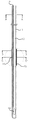
도 1은 본 발명의 바람직한 실시 형태에 따른 위장관 삽입용 카테터를 예시한 사시도이다.
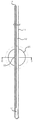
도 2는 도 1의 카테터에서 부풀림부가 확장된 상태를 예시한 사시도이다.
도 3은 본 발명에 의한 위장관 삽입용 카테터의 내부 구성을 설명하기 위하여 예시한 도 1의 주요부분 확대 단면도이다.
도 4는 본 발명에 의한 위장관 삽입용 카테터의 부풀림부가 확장된 상태를 설명하기 위하여 예시한 도 2의 주요부분 확대 단면도이다.
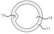
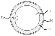
도 5a 내지 도 5d는 도 3 및 도 4의 주요부분 확대 단면도들이다.
도 6은 본 발명에 의한 위장관 삽입용 카테터가 위장관에 삽입된 상태에서 부풀림부가 분문 바로 아래쪽에서 확장된 상태를 예시한 참고도이다.1 is a perspective view illustrating a catheter for insertion of a gastrointestinal tract according to a preferred embodiment of the present invention.
2 is a perspective view illustrating a state in which the bulge is expanded in the catheter of FIG. 1.
Figure 3 is an enlarged cross-sectional view of the main part of Figure 1 illustrated to explain the internal configuration of the catheter for insertion of the gastrointestinal tract according to the present invention.
Figure 4 is an enlarged cross-sectional view of the main portion of Figure 2 illustrated to explain the expanded state of the bulge portion of the catheter for insertion of the gastrointestinal tract according to the present invention.
5A to 5D are enlarged cross-sectional views of main parts of FIGS. 3 and 4.
Figure 6 is a reference diagram illustrating a state in which the bulge is expanded immediately below the powder in the state in which the catheter for insertion of the gastrointestinal tract according to the present invention is inserted into the gastrointestinal tract.
이하, 본 발명의 바람직한 실시 형태에 의한 위장관 삽입용 카테터의 구성 및 동작을 첨부한 도면을 참조하여 상세히 설명한다.Hereinafter, with reference to the accompanying drawings, the configuration and operation of the catheter for insertion of the gastrointestinal tract according to a preferred embodiment of the present invention will be described in detail.
본 명세서 및 청구범위에 사용된 용어나 단어는 통상적이거나 사전적인 의미로 한정 해석되지 아니하며, 발명자는 그 자신의 발명을 가장 최선의 방법으로 설명하기 위해 용어의 개념을 적절하게 정의할 수 있다는 원칙에 입각하여 본 발명의 기술적 사상에 부합하는 의미와 개념으로 해석되어야만 한다. 따라서, 본 명세서에 기재된 실시예와 도면에 도시된 구성은 본 발명의 가장 바람직한 일 실시예에 불과할 뿐이므로, 본 출원시점에 있어서 이들을 대체할 수 있는 다양한 균등물과 변형예들이 있을 수 있음을 이해하여야 한다.It is to be understood that the words or words used in the present specification and claims are not to be construed in a conventional or dictionary sense and that the inventor can properly define the concept of a term in order to describe its invention in the best possible way And should be construed in light of the meanings and concepts consistent with the technical idea of the present invention. Therefore, since the embodiments shown in the specification and the configuration shown in the drawings is only one of the most preferred embodiment of the present invention, it is understood that there may be various equivalents and modifications that can replace them at the time of the present application shall.
도 1은 본 발명의 바람직한 실시 형태에 따른 위장관 삽입용 카테터를 예시한 사시도이고, 도 2는 도 1의 카테터에서 부풀림부가 확장된 상태를 예시한 사시도이며, 도 3은 본 발명에 의한 위장관 삽입용 카테터의 내부 구성을 설명하기 위하여 도 1의 주요 부분을 세로 방향으로 절개하여 예시한 확대 단면도이고, 도 4는 본 발명에 의한 카테터의 부풀림부가 확장된 상태를 설명하기 위하여 도 2의 주요부분을 세로방향으로 절개하여 예시한 확대 단면도이며, 도 5a 내지 도 5d는 도 3 및 도 4의 주요부분을 가로방향으로 절개하여 예시한 확대 단면도들로서, 도 5a는 도 3의 A-A'선 단면도이고, 도 5b는 도 3의 B-B'선 단면도이며, 도 5c는 도 3의 C-C'선 단면도이고, 도 5d는 도 4의 D-D'선 단면도이다. 1 is a perspective view illustrating a gastrointestinal insertion catheter according to a preferred embodiment of the present invention, Figure 2 is a perspective view illustrating an expanded state in the catheter of Figure 1, Figure 3 is a gastrointestinal insertion according to the present invention In order to explain the internal configuration of the catheter is an enlarged cross-sectional view illustrating the main portion of Figure 1 by cutting in the vertical direction, Figure 4 is a vertical portion of the main portion of Figure 2 to explain the expanded state of the catheter according to the present invention 5A through 5D are enlarged cross-sectional views illustrating the main parts of FIGS. 3 and 4 being cut in the horizontal direction, and FIG. 5A is a cross-sectional view taken along line AA ′ of FIG. 3. 5B is a cross-sectional view taken along the line BB ′ of FIG. 3, FIG. 5C is a cross-sectional view taken along the line C-C ′ of FIG. 3, and FIG. 5D is a cross-sectional view taken along the line D-D ′ of FIG. 4.
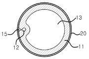
본 발명의 위장관 삽입용 카테터는, 튜브형 몸체(11)의 일단부에 튜부형 몸체(11) 내로부터 유체의 유출(또는 위내용물 유입)을 위한 제1개방부(14)를 구비하며, 다른 일단부에는 튜부형 몸체(11) 내로 유체의 유입(또는 위내용물 유출)을 위한 제2개방부(13a)를 구비하며, 제2개방부(13a)에는 탈부착 가능한 마개(30)를 구비한다.The catheter for insertion of the gastrointestinal tract of the present invention includes a first
제2개방부의 부근에 튜브형 몸체(11)에서 분지되어 이루어진 유체주입구(12a)를 통해 기체 등의 유체를 유입하기 위한 유체 주입관(12)을 더 구비하며, 유체 주입관(12)은 튜브형 몸체(11) 내에 위치되되, 식도와 위의 접합부위에 부풀림부(풍선)(20)이 위치하도록 이루어지며, 상기 풍선으로부터 튜브형 몸체(11)의 선단부(팁)의 끝까지의 길이가 길도록 이루어진다. 본 발명에서는 풍선으로부터 튜브형 몸체(11)의 선단부(팁)의 끝까지의 길이가 약 20cm 되도록 이루어질 수 있다.A
즉, 도 1 내지 도 4에서와 같이, 본 발명에 의한 카테터(10)는 몸체의 내부에 유체 주입관(12)과 제1유로(13)가 각각 서로 독립된 공간을 갖도록 길이방향을 따라 일체로 형성된 튜브형 몸체(11)로 이루어지고, 이 튜브형 몸체(11)의 후단부에는 유체 주입관(12)으로부터 연설되는 유체 주입구(12a)와 제1유로(13)로부터 연설장되는 제2개방부(13a)가 각각 단부에서 분기되어 형성되며, 제2개방부(13a)에는 제2개방부를 개폐할 수 있는 마개(30)가 탈부착 가능하게 부착되고, 튜브형 몸체(11)의 선단부 쪽 외주면에는 반경 방향으로 부피 확장이 가능하게 부풀림부(20)가 일체로 형성되어 구성된다. 이때 유체 주입구(12a)는 공기 주입을 위한 노즐 등이 삽입되는 경우 탄력에 의해 주입구가 자동으로 개방되고 외부 노즐을 분리시키는 경우 복원력에 의해 주입구가 강제로 폐쇄되는 재질로 구성되는 것이 바람직할 것이다. That is, as shown in Figures 1 to 4, the
튜브형 몸체(11)는 액체 또는 기체의 유출입을 위해 몸체의 선단부와 후단부가 도 1 및 도 2에 도시된 바와 같이 각각 개방되고, 선,후단부를 통해 유출입되는 액체 또는 기체의 흐름을 위한 제1유로(13)가 몸체 내부에 길이방향으로 형성된다. 이 튜브형 몸체(11)의 선단부는 라운드 형상으로서 막힌 상태로 형성되고 튜브형 몸체(11)의 선단부 측면에는 유체의 유출입을 위한 제1개방부(14)가 측면을 향해 개방되어 형성된다. 또한 이 튜브형 몸체(11)는 부풀림부(20)가 위치하는 부분의 측면에 부풀림부(20)의 내부 공간과 유체 주입관(12)의 내부 공간을 서로 연결하는 연결통로(15)가 도 3과 도 4 및 도 5c 및 도 5d와 같이 형성되어 유체 주입관(12)을 통해 공급되는 유체가 부풀림부(20)의 내부로 공급될 수 있도록 구성된다.The
유체 주입관(12)은 도 5a 내지 도 5d에 도시된 바와 같이 부풀림부(20)의 내부 압력 조절에 필요한 유체를 튜브형 몸체(11)의 내부를 통해 공급할 수 있도록 튜브형 몸체(11)의 내부에 일체로 길이방향을 따라 형성되며, 이 유체 주입관(12)은 부풀림부(20)의 내부 압력 조절에 필요한 유체(예를 들어 공기)를 튜브형 몸체(11)의 후단부의 공기 주입구(12a)를 통해 공급할 수 있도록 튜브형 몸체(11)의 후단부로부터 부풀림부(20)까지 연설되어 형성된다. The
부풀림부(20)는 도 5b 내지 도 5d에 도시된 바와 같이 튜브형 몸체(11)의 외주면을 둘러 감싸는 형태로 일체로 형성되며, 내부 압력에 의해 부피가 증가되는 경우 직경이 반경방향으로 확장될 수 있도록 탄성 부재로 이루어지며, 그 확장된 상태의 내부 공간(21)이 구형상으로 확장 가능하도록 형성되는 것이 바람직하다. 이로써 부풀림부(20)의 직경 확장에 의해 튜브형 몸체(11)의 선단부가 상부식도 쪽으로 탈리되는 것을 방지할 수 있게 될 것이다. 특히 이 부풀림부(20)는 튜브형 몸체(11)의 선단부로부터 일정 거리 이격되는 위치에 형성되되, 도 3 및 도 4에 도시된 바와 같이 부풀림부(20)가 식도와 위장 사이의 분문(유문) 바로 아래쪽에 위치할 수 있도록 위장 내 저면(전정부)에서 분문까지의 거리 만큼 튜브형 몸체(11)의 선단부로부터 약 10cm정도 이격되어 형성되는 것이 바람직하다.The inflated
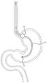
도 6은 본 발명에 의한 카테터가 위장관에 삽입된 상태에서 부풀림부가 분문 바로 아래쪽에서 확장된 상태를 예시한 참고도로서, 이상과 같이 구성되는 본 발명의 위장관 삽입용 카테터의 동작 및 그에 의한 작용 효과를 설명한다.Figure 6 is a reference diagram illustrating a state in which the bulging portion is expanded immediately below the powder in the state in which the catheter is inserted into the gastrointestinal tract, the operation of the gastrointestinal insertion catheter of the present invention configured as described above and the effects thereof Explain.
먼저, 본 발명에 의한 카테터(10)를 도 1 및 도 3과 같이 부풀림부(20)가 확장되지 않은 상태에서 선단부부터 구강 또는 비강으로 삽입하여 식도를 통해 위장관 내부의 저면까지 삽입되게 하고, 이 후 카테터 후단부의 유체 주입구(12a)을 통해 유체 주입관(12)으로 공기 등의 유체를 주입하게 되면, 유체 주입관(12)을 따라 주입된 유체는 부풀림부(20)와 유체 주입관(12) 사이에 형성된 연결 통로(15)를 통해 부풀림부(20)의 내부까지 유입될 수 있게 된다. 이에 따라 부풀림부(20) 내부로 유입되는 유체의 부피가 증가하게 되면서 그 내부 압력이 서서히 증가하게 되고, 탄성 부재로 이루어진 부풀림부(20)는 이러한 내부 압력의 증가에 의해 그 표면이 늘어나게 되어 그 직경이 도 2 및 도 4에 도시된 바와 같이 튜브형 몸체(11)의 외주면으로부터 반경방향으로 확장되고, 구형상의 부풀림부(20)가 형성될 수 있게 된다. 따라서 본 발명에 의한 카테터를 이용하게 되는 경우 카테터(10)의 부풀림부(20)를 도 6에 예시된 바와 같이 식도와 위장 사이의 분문 바로 아래쪽에 위치시킨 상태에서 확장시키는 것이 가능하게 된다. First, the
이러한 상태로 위장에 삽입되어 있는 카테터를 이용하게 되면, 카테터가 위장관으로부터 빠질 염려가 없기 때문에 위장 내 가스와 분비물의 제거, 또는 검사에 필요한 위 내용물의 추출, 또는 음식물과 약물을 위장관 내부로 직접 투여, 또는 상부 위장관 출혈시 위세척 등의 처치를 안전하게 실시하는 것이 가능하게 된다. 이러한 추출 또는 투여 등의 처리 동작은 특히 마개(30)를 열어 제2개방부(13a)를 개방시킨 상태에서 튜브형 몸체(11) 내부에 형성된 제1유로(13)를 통해 이루어질 수 있게 되는데, 이때 튜브형 몸체(11)의 선단부는 라운드 형상으로서 막힌 상태로 형성되고 튜브형 몸체(11)의 선단부 측면에는 유체의 유출입을 위한 제1개방부(14)가 형성되어 있게 되므로, 튜브형 몸체의 단부가 위장관의 저면에 맞닿아 위치하게 되더라도 위장관의 저면이 튜브형 몸체의 제1개방부(14)를 막지 않게 된다. When using a catheter inserted into the gastrointestinal tract in this state, the catheter does not have to be removed from the gastrointestinal tract, so that gas and secretion of the gastrointestinal tract is removed, gastric contents required for examination, or food and drugs are directly administered into the gastrointestinal tract. In the event of bleeding from the upper gastrointestinal tract, gastric lavage or the like can be safely performed. The treatment operation such as extraction or administration can be made through the
이후 구강이나 비강으로 삽입된 후 카테터를 제거하고자 하는 경우에는 유체 주입관(12)의 단부에 연설된 유체 주입구(12a)를 통해 개방하게 되면 부풀림부(20)에 주입된 유체가 연결통로(15) 및 유체 주입관(12)을 통해 주입시와는 반대 방향으로 배출되면서 부풀림부(20)의 직경이 원래의 상태로 축소될 수 있게 되며, 따라서 식도 및 분문을 통해 위장관의 내부로 삽입되어 있던 카테터를 손쉽게 탈리시킬 수 있게 된다.Then, when the catheter is to be removed after being inserted into the oral cavity or the nasal cavity, the fluid injected into the swelling
이상과 같이 본 발명은 비록 한정된 실시예와 도면에 의해 설명되었으나, 본 발명은 상기의 실시예에 한정되는 것은 아니며, 이는 본 발명이 속하는 분야에서 통상의 지식을 가진 자라면 이러한 기재로부터 다양한 수정 및 변형이 가능하다. 따라서, 본 발명의 사상은 아래에 기재된 특허청구범위에 의해서만 파악되어야 하고, 이의 균등 또는 등가적 변형 모두는 본 발명 사상의 범주에 속한다고 할 것이다.As described above, the present invention has been described by way of limited embodiments and drawings, but the present invention is not limited to the above-described embodiments, which can be variously modified and modified by those skilled in the art to which the present invention pertains. Modifications are possible. Accordingly, it is intended that the scope of the invention be defined by the claims appended hereto, and that all equivalent or equivalent variations thereof fall within the scope of the present invention.
10 : 카테터 11 : 튜브형 몸체
12 : 유체 주입관 12a : 유체 주입구
13 : 제1유로 13a : 제2개방부
14 : 제1개방부 15 : 연결통로
20 : 부풀림부 21 : 내부 공간
30 : 마개10: catheter 11: tubular body
12:
13:
14: first opening 15: connecting passage
20: inflated portion 21: the interior space
30: stopper
Claims (13)
상기 제2개방부의 주변에 튜브형 몸체에서 분지되어 이루어진 유체주입구를 구비하며, 상기 유체주입구와 연결된 유체주입관은 튜브형 몸체 내에 위치되며,
상기 유체주입관은 식도와 위의 접합부위에 위치되도록 이루어진 부풀림부를 구비하는 것을 특징으로 하는 위장관 삽입용 카테터.One end of the tubular body is provided with a first opening for outflow of the fluid or inflow of gastric contents from within the tubular body, and the other end has a second opening for inflow of fluid or outflow of gastric contents into the tubular body. It is provided, but the second open portion is provided with a removable stopper,
A fluid inlet formed branched from the tubular body around the second opening, and the fluid inlet pipe connected to the fluid inlet is located in the tubular body,
The fluid injection tube has a gastrointestinal insertion catheter characterized in that it has an inflated portion made to be located at the junction of the esophagus and stomach.
상기 부풀림부는 풍선으로 이루어지는 것을 특징으로 하는 위장관 삽입용 카테터.The method of claim 1,
The bulge is catheter for insertion of the gastrointestinal tract, characterized in that consisting of a balloon.
상기 부풀림부로부터 튜브형 몸체의 선단부의 끝까지의 길이가 20cm 되도록 이루어진 것을 특징으로 하는 위장관 삽입용 카테터.The method of claim 2,
Catheter for insertion of the gastrointestinal tract, characterized in that the length from the inflated portion to the end of the tip of the tubular body is 20cm.
상기 부풀림부는 튜브형 몸체의 선단부로부터 일정 거리 이격되는 위치에 형성되며, 내부 압력에 의해 직경이 확장 또는 축소되어 상기 튜브형 몸체의 선단부가 위장관으로부터 탈리되는 것을 방지하도록 이루어진 것을 특징으로 하는 위장관 삽입용 카테터.The method of claim 1,
The inflation portion is formed in a position spaced apart from the front end of the tubular body, the diameter of the tubular body insertion catheter, characterized in that the expansion or contraction by the internal pressure to prevent the tip of the tubular body detached from the gastrointestinal tract.
상기 부풀림부가, 식도와 위장 사이의 분문 아래쪽에 위치할 수 있도록, 위장 내 저면에서 분문까지의 거리 만큼, 상기 튜브형 몸체의 선단부로부터 이격되어 형성되는 것을 특징으로 하는 위장관 삽입용 카테터.The method of claim 4, wherein
A catheter for insertion of a gastrointestinal tract, wherein the bulge is spaced apart from the distal end of the tubular body by a distance from the bottom of the gastrointestinal tract to the intestine so that the bulge is located below the body between the esophagus and the stomach.
상기 튜브형 몸체의 선단부로부터 일정 거리 이격되는 위치에 형성되며, 내부 압력에 의해 직경이 확장 또는 축소되어 상기 튜브형 몸체의 선단부가 위장관으로부터 탈리되는 것을 방지하는 부풀림부;
상기 부풀림부의 내부 압력 조절에 필요한 유체를 공급할 수 있도록 상기 튜브형 몸체의 후단부에서 상기 부풀림부까지 이어지는 유로를 형성하는 유체 주입관;을 포함하여 구성되는 것을 특징으로 하는 위장관 삽입용 카테터.A gastrointestinal insertion catheter comprising a tubular body in which a front end and a rear end of a body are respectively opened for the inflow and outflow of liquid or gas, and a first flow path for the flow of liquid or gas flows through each opening is formed therein,
An inflation portion formed at a position spaced apart from the distal end of the tubular body by an internal pressure to expand or contract the diameter to prevent the distal end of the tubular body from being detached from the gastrointestinal tract;
And a fluid injection tube forming a flow path extending from the rear end of the tubular body to the inflation portion so as to supply a fluid required for adjusting the internal pressure of the inflation portion.
내부 압력에 의해 직경이 확장 또는 축소되는 부풀림부가 상기 튜브형 몸체의 선단부로부터 이격되어 형성되되, 상기 부풀림부가 식도와 위장 사이의 분문 바로 아래쪽에 위치할 수 있도록 위장 내 저면(전정부)에서 분문까지의 거리 만큼 상기 튜브형 몸체의 선단부로부터 이격되어 형성되고,
상기 부풀림부의 내부 압력 조절에 필요한 유체를 상기 튜브형 몸체의 후단부로부터 공급할 수 있도록 상기 부풀림부까지 이어지는 유체 주입관;을 형성하여 구성되는 것을 특징으로 하는 위장관 삽입용 카테터.In the gastrointestinal insertion catheter comprising a tubular body in which the front and rear ends of the body are respectively opened for the inflow and outflow of liquid or gas, and the first passage 13 for the flow of the liquid or gas flows through each opening is formed therein. ,
An inflation portion, the diameter of which is expanded or reduced by internal pressure, is formed spaced apart from the distal end of the tubular body. Is formed spaced apart from the front end of the tubular body by a distance,
And a fluid injection tube leading to the inflation portion so as to supply the fluid necessary for adjusting the internal pressure of the inflation portion from the rear end of the tubular body.
상기 튜브형 몸체의 내부에 일체로 형성되며, 상기 튜브형 몸체의 길이방향으로 형성되는 것을 특징으로 하는 위장관 삽입용 카테터.The fluid injection tube according to any one of claims 6 and 7,
A catheter for insertion of the gastrointestinal tract, which is integrally formed in the tubular body and is formed in the longitudinal direction of the tubular body.
상기 부풀림부가 위치하는 부분의 튜브형 몸체에는 상기 부풀림부의 내부 공간과 상기 유체 주입관의 내부 공간을 서로 연결하는 연결통로가 형성된 것을 특징으로 하는 위장관 삽입용 카테터.8. The method according to any one of claims 6 to 7,
The gastrointestinal insertion catheter, characterized in that the tubular body of the portion in which the inflated portion is formed a connecting passage connecting the inner space of the inflated portion and the inner space of the fluid injection tube.
상기 튜브형 몸체와 일체로 형성되며, 상기 튜브형 몸체의 외주면을 둘러 감싸는 형태로 형성되는 것을 특징으로 하는 위장관 삽입용 카테터.The swelling part according to any one of claims 6 to 7,
Is formed integrally with the tubular body, the catheter for insertion of the gastrointestinal tract, characterized in that formed in the form surrounding the outer peripheral surface of the tubular body.
내부 압력에 의해 부피의 확장 및 축소가 가능한 탄성부재로 형성되는 것을 특징으로 위장관 삽입용 카테터.The swelling part according to any one of claims 6 to 7,
Catheter for insertion of the gastrointestinal tract, characterized in that formed by an elastic member capable of expanding and contracting the volume by the internal pressure.
내부 압력에 의해 부피가 확장된 상태의 내부 공간이 구형상으로 확장되는 것을 특징으로 하는 위장관 삽입용 카테터.The swelling part according to any one of claims 6 to 7,
Catheter for insertion of the gastrointestinal tract, characterized in that the inner space of the volume is expanded by the internal pressure is expanded in a spherical shape.
상기 튜브형 몸체의 선단부는 라운드 형상으로서 막힌 상태로 형성되고 상기 튜브형 몸체의 선단부 측면에 유체의 유출입을 위한 제1개방부가 형성되는 것을 특징으로 하는 위장관 삽입용 카테터.
8. The method according to any one of claims 6 to 7,
Catheter for insertion of the gastrointestinal tract, characterized in that the front end of the tubular body is formed in a closed state in a clogged state and a first open portion for the inflow and outflow of fluid is formed on the front end side of the tubular body.
Applications Claiming Priority (2)
| Application Number | Priority Date | Filing Date | Title |
|---|---|---|---|
| KR20110034688 | 2011-04-14 | ||
| KR1020110034688 | 2011-04-14 |
Publications (1)
| Publication Number | Publication Date |
|---|---|
| KR20120117618A true KR20120117618A (en) | 2012-10-24 |
Family
ID=47285548
Family Applications (1)
| Application Number | Title | Priority Date | Filing Date |
|---|---|---|---|
| KR1020110103111A Ceased KR20120117618A (en) | 2011-04-14 | 2011-10-10 | Catheter for inserting into a gastric |
Country Status (1)
| Country | Link |
|---|---|
| KR (1) | KR20120117618A (en) |
Cited By (1)
| Publication number | Priority date | Publication date | Assignee | Title |
|---|---|---|---|---|
| KR20160112418A (en) | 2015-03-19 | 2016-09-28 | 고려대학교 산학협력단 | Stomach tube for providing food |
-
2011
- 2011-10-10 KR KR1020110103111A patent/KR20120117618A/en not_active Ceased
Cited By (1)
| Publication number | Priority date | Publication date | Assignee | Title |
|---|---|---|---|---|
| KR20160112418A (en) | 2015-03-19 | 2016-09-28 | 고려대학교 산학협력단 | Stomach tube for providing food |
Similar Documents
| Publication | Publication Date | Title |
|---|---|---|
| ES2834620T3 (en) | Inflatable and detachable balloon, intended to be implanted in a body cavity, associated treatment kit and emptying method | |
| EP3116574B1 (en) | Improved laryngeal mask | |
| US8075521B2 (en) | Catheter | |
| US7121280B2 (en) | Medical devices and methods of selectively and alternately isolating bronchi or lungs | |
| US20130220332A1 (en) | Laryngeal mask with enhanced insertion | |
| EP3053622B1 (en) | Artificial airway device | |
| KR102423196B1 (en) | Tracheal tube and suction device | |
| CN111601631B (en) | Airway dilation device and related method for deployment | |
| JP7245596B2 (en) | Suction device for medical device and medical device system including suction device | |
| GB2489407A (en) | Laryngeal mask and tracheal tube airway devices | |
| CN109939320B (en) | Nasopharynx ventilation pipeline | |
| CN110464653A (en) | A kind of multi-lumen sliding gastric tube | |
| US20140213969A1 (en) | Expandable Inter Vivos Tube | |
| US20120232525A1 (en) | Suction device | |
| US9010332B2 (en) | Expandable inter vivos tube | |
| US20140238405A1 (en) | Expandable Inter Vivos Tube | |
| KR20120117618A (en) | Catheter for inserting into a gastric | |
| US20210113798A1 (en) | Connector | |
| CN109310838A (en) | fixing device for laryngeal mask | |
| JP2009247870A (en) | Catheter for expansion of nasal cavity and its auxiliary mask | |
| JP3153651U (en) | Nasal tube feeding catheter with drop-off prevention cuff | |
| CN209221233U (en) | A kind of double bolloon Medical throat cover | |
| JP2017505173A (en) | Tracheal tube | |
| CN210728382U (en) | Trachea catheter for anesthesia in airway interventional stent implantation | |
| JP7078957B2 (en) | Tracheostomy tube with side holes that can be opened and closed freely |
Legal Events
| Date | Code | Title | Description |
|---|---|---|---|
| A201 | Request for examination | ||
| A302 | Request for accelerated examination | ||
| PA0109 | Patent application |
Patent event code: PA01091R01D Comment text: Patent Application Patent event date: 20111010 |
|
| PA0201 | Request for examination | ||
| PA0302 | Request for accelerated examination |
Patent event date: 20111010 Patent event code: PA03022R01D Comment text: Request for Accelerated Examination |
|
| E902 | Notification of reason for refusal | ||
| PE0902 | Notice of grounds for rejection |
Comment text: Notification of reason for refusal Patent event date: 20120305 Patent event code: PE09021S01D |
|
| PG1501 | Laying open of application | ||
| E601 | Decision to refuse application | ||
| PE0601 | Decision on rejection of patent |
Patent event date: 20121108 Comment text: Decision to Refuse Application Patent event code: PE06012S01D Patent event date: 20120305 Comment text: Notification of reason for refusal Patent event code: PE06011S01I |
|
| J201 | Request for trial against refusal decision | ||
| PJ0201 | Trial against decision of rejection |
Patent event date: 20121210 Comment text: Request for Trial against Decision on Refusal Patent event code: PJ02012R01D Patent event date: 20121108 Comment text: Decision to Refuse Application Patent event code: PJ02011S01I Appeal kind category: Appeal against decision to decline refusal Decision date: 20140219 Appeal identifier: 2012101010371 Request date: 20121210 |
|
| J301 | Trial decision |
Free format text: TRIAL DECISION FOR APPEAL AGAINST DECISION TO DECLINE REFUSAL REQUESTED 20121210 Effective date: 20140219 |
|
| PJ1301 | Trial decision |
Patent event code: PJ13011S01D Patent event date: 20140219 Comment text: Trial Decision on Objection to Decision on Refusal Appeal kind category: Appeal against decision to decline refusal Request date: 20121210 Decision date: 20140219 Appeal identifier: 2012101010371 |