KR20120112468A - Syringe - Google Patents
Syringe Download PDFInfo
- Publication number
- KR20120112468A KR20120112468A KR1020127015839A KR20127015839A KR20120112468A KR 20120112468 A KR20120112468 A KR 20120112468A KR 1020127015839 A KR1020127015839 A KR 1020127015839A KR 20127015839 A KR20127015839 A KR 20127015839A KR 20120112468 A KR20120112468 A KR 20120112468A
- Authority
- KR
- South Korea
- Prior art keywords
- plunger
- orientation
- barrel
- syringe
- collar
- Prior art date
Links
Images

Classifications
-
- A—HUMAN NECESSITIES
- A61—MEDICAL OR VETERINARY SCIENCE; HYGIENE
- A61M—DEVICES FOR INTRODUCING MEDIA INTO, OR ONTO, THE BODY; DEVICES FOR TRANSDUCING BODY MEDIA OR FOR TAKING MEDIA FROM THE BODY; DEVICES FOR PRODUCING OR ENDING SLEEP OR STUPOR
- A61M5/00—Devices for bringing media into the body in a subcutaneous, intra-vascular or intramuscular way; Accessories therefor, e.g. filling or cleaning devices, arm-rests
- A61M5/178—Syringes
- A61M5/31—Details
- A61M5/315—Pistons; Piston-rods; Guiding, blocking or restricting the movement of the rod or piston; Appliances on the rod for facilitating dosing ; Dosing mechanisms
- A61M5/31565—Administration mechanisms, i.e. constructional features, modes of administering a dose
- A61M5/3159—Dose expelling manners
- A61M5/31591—Single dose, i.e. individually set dose administered only once from the same medicament reservoir, e.g. including single stroke limiting means
-
- A—HUMAN NECESSITIES
- A61—MEDICAL OR VETERINARY SCIENCE; HYGIENE
- A61M—DEVICES FOR INTRODUCING MEDIA INTO, OR ONTO, THE BODY; DEVICES FOR TRANSDUCING BODY MEDIA OR FOR TAKING MEDIA FROM THE BODY; DEVICES FOR PRODUCING OR ENDING SLEEP OR STUPOR
- A61M5/00—Devices for bringing media into the body in a subcutaneous, intra-vascular or intramuscular way; Accessories therefor, e.g. filling or cleaning devices, arm-rests
- A61M5/178—Syringes
- A61M5/31—Details
- A61M5/315—Pistons; Piston-rods; Guiding, blocking or restricting the movement of the rod or piston; Appliances on the rod for facilitating dosing ; Dosing mechanisms
- A61M5/31565—Administration mechanisms, i.e. constructional features, modes of administering a dose
- A61M5/31576—Constructional features or modes of drive mechanisms for piston rods
- A61M5/31578—Constructional features or modes of drive mechanisms for piston rods based on axial translation, i.e. components directly operatively associated and axially moved with plunger rod
- A61M5/3158—Constructional features or modes of drive mechanisms for piston rods based on axial translation, i.e. components directly operatively associated and axially moved with plunger rod performed by axially moving actuator operated by user, e.g. an injection button
-
- A—HUMAN NECESSITIES
- A61—MEDICAL OR VETERINARY SCIENCE; HYGIENE
- A61M—DEVICES FOR INTRODUCING MEDIA INTO, OR ONTO, THE BODY; DEVICES FOR TRANSDUCING BODY MEDIA OR FOR TAKING MEDIA FROM THE BODY; DEVICES FOR PRODUCING OR ENDING SLEEP OR STUPOR
- A61M5/00—Devices for bringing media into the body in a subcutaneous, intra-vascular or intramuscular way; Accessories therefor, e.g. filling or cleaning devices, arm-rests
- A61M5/178—Syringes
- A61M5/31—Details
- A61M5/315—Pistons; Piston-rods; Guiding, blocking or restricting the movement of the rod or piston; Appliances on the rod for facilitating dosing ; Dosing mechanisms
- A61M5/31501—Means for blocking or restricting the movement of the rod or piston
- A61M2005/31508—Means for blocking or restricting the movement of the rod or piston provided on the piston-rod
Abstract
유체를 분배하기 위한 주사기 (2)가 개시되며, 이 주사기는 배출 통로를 한정하는 배출 단부 (10)를 포함하는 배럴 (4), 및 배럴 내부에 배치되는 플런저 (15)를 포함하고, 플런저는 플런저와 배출 단부가 배럴 내부에서 가변 체적 챔버를 한정하도록, 및 플런저가 유체를 챔버로부터 배출 통로를 통해 변위시킬 수 있도록 배럴 내부에서 이동하도록 구성되며, 여기서 주사기는 주사기의 종축을 중심으로 회전하도록 구성되고 배럴의 배출 단부에 대한 제1 축방향 배향을 갖는 회전 요소 (20a, 20b, 24a, 24b)를 포함하고, 회전 요소의 제1 배향에서 플런저의 축방향 이동을 제한하도록 구성된 제1 멈춤부가 플런저 및/또는 배럴 상에 제공되며, 회전 요소는 배럴의 배출 단부에 대한 제2 축방향 배향을 가지며, 여기서 제1 멈춤부는 맞닿음 해제되고 플런저의 이동은 제2 멈춤부까지 허용된다.A syringe 2 for dispensing fluid is disclosed, which includes a barrel 4 comprising a discharge end 10 defining a discharge passageway, and a plunger 15 disposed inside the barrel, the plunger being a Configured to move inside the barrel such that the plunger and the discharge end define a variable volume chamber inside the barrel, and the plunger can displace fluid from the chamber through the discharge passage, wherein the syringe is configured to rotate about the longitudinal axis of the syringe And a rotating element 20a, 20b, 24a, 24b having a first axial orientation with respect to the discharge end of the barrel, the first stop configured to limit the axial movement of the plunger in the first orientation of the rotating element And / or provided on the barrel, the rotating element having a second axial orientation with respect to the discharge end of the barrel, wherein the first stop is abutted and movement of the plunger is stopped. Up to 2 stops are allowed.
Description
본 발명은 주사기에 관한 것으로, 특히 프라이밍(priming) 및 후속된 예정된 용량의 투여를 허용하도록 구성된 주사기에 관한 것이다.The present invention relates to a syringe, and more particularly to a syringe configured to allow priming and subsequent administration of a predetermined dose.
정확하고도 재현가능한 방법으로 주사기로부터 비교적 작은 체적의 유체를 전달하는 것이 종종 바람직하다. 전형적으로, 유체를 수용하고 있는 주사기는 주사기 내에 어떠한 공기 또는 다른 가스도 존재하지 않음을 보장하기 위하여 먼저 프라이밍되며, 그리고 나서 요구되는 체적의 유체를 전달하기 위하여 제2의 전달 (투여) 단계가 수행된다. 그러나, 종래의 주사기를 사용하여 전달 단계 동안에 비교적 작은 체적의 유체를 정확하게 전달하는 것이 어렵다.It is often desirable to deliver a relatively small volume of fluid from a syringe in an accurate and reproducible manner. Typically, the syringe containing the fluid is first primed to ensure that no air or other gas is present in the syringe, and then a second delivery (administration) step is performed to deliver the required volume of fluid. do. However, it is difficult to accurately deliver relatively small volumes of fluid during the delivery step using conventional syringes.
WO01/62319, US3,934,586 및 WO03/004080 모두 2중 단계 주사기를 기술하고 있지만, 이들 중 어느 것도 비교적 작은 체적의 유체를 정확하고 재현가능하게 전달하는 문제를 다루고 있지 않다.WO 01/62319, US 3,934,586 and WO 03/004080 all describe dual stage syringes, but none of them address the problem of delivering relatively small volumes of fluid accurately and reproducibly.
본 발명의 제1 측면에 따르면, 유체를 분배하기 위한 주사기가 제공되며, 이 주사기는 배출 통로를 한정하는 배출 단부를 포함하는 배럴(barrel), 및 배럴 내부에 배치되는 플런저를 포함하고, 플런저는 플런저와 배출 단부가 배럴 내부에서 가변 체적 챔버를 한정하도록, 및 플런저가 유체를 챔버로부터 배출 통로를 통해 변위시킬 수 있도록 배럴 내부에서 이동하도록 구성되며, 주사기는 주사기의 종축을 중심으로 회전하도록 구성되고 배럴의 배출 단부에 대한 제1 축방향 배향을 갖는 회전 요소를 포함하고, 회전 요소의 제1 배향에서 플런저의 축방향 이동을 제한하도록 구성된 제1 멈춤부가 플런저 및/또는 배럴 상에 제공되며, 회전 요소는 배럴의 배출 단부에 대한 제2 축방향 배향을 갖는데, 여기서 제1 멈춤부가 맞닿음 해제되고 플런저의 이동이 제2 멈춤부까지 허용된다.According to a first aspect of the invention there is provided a syringe for dispensing a fluid, the syringe comprising a barrel comprising a discharge end defining a discharge passageway, and a plunger disposed inside the barrel, wherein the plunger is Configured to move inside the barrel such that the plunger and discharge end define a variable volume chamber inside the barrel, and the plunger can displace fluid from the chamber through the discharge passage, the syringe configured to rotate about the longitudinal axis of the syringe; A first stop provided on the plunger and / or the barrel, the first stop being provided with a rotating element having a first axial orientation relative to the discharge end of the barrel, the first stop configured to limit the axial movement of the plunger in the first orientation of the rotating element The element has a second axial orientation with respect to the discharge end of the barrel, wherein the first stop is abutted and movement of the plunger is second Allowed up to the stop.
본 발명에 따르면, 플런저는 제1 멈춤부가 맞닿을 때까지 제1 축방향 배향에서 배출 단부를 향해 변위될 수 있다. 이는 프라이밍 단계를 구성한다. 그리고 나서, 회전 요소는 제1 축방향 배향으로부터 제2 축방향 배향으로 회전되는데, 그 결과 제1 멈춤부는 맞닿음 해제되거나 우회되며, 플런저는 제2 멈춤부를 향해 추가로 변위될 수 있다. 제1 멈춤부와 제2 멈춤부 사이의 간격은 특정 배럴 내경에 대하여 전달 단계 동안에 주사기로부터 분배되는 체적을 한정한다. 비교적 작은 체적의 유체에 있어서, 제1 멈춤부로부터 제2 멈춤부까지의 변위는 비교적 짧지만, 본 발명에 따른 주사기에 의해 정확하게 제어된다.According to the invention, the plunger can be displaced towards the discharge end in the first axial orientation until the first stop abuts. This constitutes a priming step. The rotating element is then rotated from the first axial orientation to the second axial orientation, such that the first stop is disengaged or bypassed and the plunger can be further displaced towards the second stop. The spacing between the first stop and the second stop defines the volume dispensed from the syringe during the delivery step for a particular barrel inner diameter. For relatively small volumes of fluid, the displacement from the first stop to the second stop is relatively short, but is precisely controlled by the syringe according to the present invention.
회전 요소는 제1 축방향 배향과 제2 축방향 배향 사이에서 회전되도록 구성된다. 따라서, 제2 축방향 배향은 전형적으로 제1 축방향 배향으로부터 각도 방향으로 변위된다.The rotating element is configured to rotate between the first axial orientation and the second axial orientation. Thus, the second axial orientation is typically displaced in the angular direction from the first axial orientation.
본 발명의 실시양태에서, 플런저는 회전 요소를 포함한다. 그러나, 대안적인 실시양태에서, 플런저의 제1 부분은 배럴의 배출 단부 및/또는 플런저의 제2 부분에 대해 회전하도록 구성될 수 있다. 또 다른 실시양태에서, 배럴의 일부분, 예를 들어 배출 단부에 대향한 배럴의 단부 부분은 회전 요소를 포함할 수 있고 배럴의 배출 단부에 대해 회전하도록 구성될 수 있다.In an embodiment of the invention, the plunger comprises a rotating element. However, in alternative embodiments, the first portion of the plunger may be configured to rotate relative to the discharge end of the barrel and / or the second portion of the plunger. In another embodiment, a portion of the barrel, for example the end portion of the barrel opposite the discharge end, may comprise a rotating element and may be configured to rotate about the discharge end of the barrel.
예를 들어, 프라이밍 단계의 완료 이전에, 제1 축방향 배향으로부터 제2 축방향 배향으로의 의도하지 않은 이동을 방지하기 위하여, 플런저가 회전 요소로 이루어지거나 또는 이를 포함하는 실시양태에서, 플런저는 플런저가 제1 멈춤부와 맞닿을 때까지 제1 배향으로부터 제2 배향으로의 플런저의 회전을 방지하도록 구성된 배향 제어 요소를 포함할 수 있다. 이는 프라이밍 단계가 완료되고 플런저가 제1 멈춤부와 맞닿을 때까지 플런저가 제1 축방향 배향에서 유지되는 것을 보장한다.For example, in embodiments where the plunger consists of or comprises a rotating element, in order to prevent unintentional movement from the first axial orientation to the second axial orientation prior to the completion of the priming step, And an orientation control element configured to prevent rotation of the plunger from the first orientation to the second orientation until the plunger abuts the first stop. This ensures that the plunger remains in the first axial orientation until the priming step is complete and the plunger abuts with the first stop.
본원의 임의의 부분에서 한정된 본 발명의 실시양태에서, 배향 제어 요소는 배럴의 적어도 일부분에 한정된 스플라인 채널 내부에 사용시 위치되는, 플런저에 의해 지탱되는 스플라인 (종방향으로 연장되는 리브(rib))을 포함한다. 예를 들어, 배럴은 배출 채널에 대향한 단부에 위치된 칼라(collar)를 포함할 수 있고, 칼라는 스플라인 채널을 한정한다.In embodiments of the invention as defined in any part of the present application, the orientation control element may be configured to support a spline (a longitudinally extending rib) supported by a plunger, which, in use, is positioned inside a spline channel defined in at least a portion of the barrel. Include. For example, the barrel may comprise a collar positioned at an end opposite the outlet channel, the collar defining the spline channel.
플런저에 의해 지탱된 스플라인의 스플라인 채널과의 상호작용은 원치 않는 이동, 예를 들어 제1 축방향 배향으로부터 제2 축방향 배향으로의 배럴에 대한 플런저의 회전을 방지한다.The interaction of the spline supported by the plunger with the spline channel prevents unwanted movement, for example rotation of the plunger relative to the barrel from the first axial orientation to the second axial orientation.
배럴에 대한 플런저의 이동, 예컨대 회전을 허용하기 위하여, 스플라인은 플런저의 종축을 중심으로 배럴에 대한 플런저의 회전을 허용하도록 구성된 노치(notch)를 포함할 수 있다. 노치는 스플라인 내부에 한정될 수 있거나, 또는 스플라인의 일 단부와 플런저의 인접한 단부 사이에서 플런저의 일부분에 의해 한정될 수 있다. 다시 말하면, 스플라인은 플런저의 단부로 연장될 수 없지만, 플런저의 단부로부터 이격된 일 단부를 가져, 플런저의 단부와 스플라인의 단부 사이에 한정된 간극이 노치를 한정하게 할 수 있다. 일 실시양태에서, 노치 또는 각각의 노치(하나 초과로 포함된 경우)는 플런저가 제1 멈춤부와 맞닿을 때에만 플런저의 회전을 허용하도록 한정된다.To allow movement, such as rotation, of the plunger relative to the barrel, the spline may include a notch configured to allow rotation of the plunger about the barrel about the longitudinal axis of the plunger. The notch may be defined inside the spline or may be defined by a portion of the plunger between one end of the spline and an adjacent end of the plunger. In other words, the spline may not extend to the end of the plunger, but may have one end spaced from the end of the plunger such that a gap defined between the end of the plunger and the end of the spline may define the notch. In one embodiment, the notch or each notch (if included in more than one) is defined to allow rotation of the plunger only when the plunger abuts with the first stop.
당업자는 플런저가 하나 초과의 스플라인을 포함할 수 있고, 스플라인 각각이 각자의 노치를 포함하되 노치들 모두가 플런저의 일 단부로부터 균등하게 이격되도록 포함한다는 것을 인지할 것이다. 이 배열에서, 노치들은 플런저 둘레에 원주방향으로 이격되어 있고, 노치들이 스플라인 채널과 동심으로 배열된 때에 플런저의 회전을 허용한다. 칼라는 배럴로부터 제거가능할 수 있고, 배럴의 단부와 결합하도록 구성될 수 있다.Those skilled in the art will appreciate that the plunger may comprise more than one spline, each of which includes a respective notch but all of the notches are evenly spaced from one end of the plunger. In this arrangement, the notches are circumferentially spaced around the plunger and allow rotation of the plunger when the notches are arranged concentrically with the spline channel. The collar may be removable from the barrel and may be configured to engage the end of the barrel.
그러한 실시양태에서, 배럴은 전형적으로 각각의 스플라인에 대해 상응하는 스플라인 채널을 포함한다.In such embodiments, the barrel typically includes a corresponding spline channel for each spline.
플런저에 대한 통상적인 배열은 십자 형상의 샤프트를 포함하는 것이다. 따라서, 본원의 임의의 부분에서 한정된 본 발명의 실시양태에서, 플런저는 배럴 내부에 위치된 피스톤, 피스톤으로부터 연장되는 긴 샤프트, 및 피스톤에 대향한 샤프트의 단부에서의 푸시 버튼을 포함하며, 여기서 플런저 샤프트는 십자형 단면 구성을 가지고, 십자형 샤프트의 각각의 아암은 모든 노치들이 푸시 버튼으로부터 균등하게 이격되도록 노치를 한정한다.A typical arrangement for a plunger is to include a cross shaped shaft. Thus, in embodiments of the invention as defined in any part of the present disclosure, the plunger includes a piston located inside the barrel, an elongated shaft extending from the piston, and a push button at the end of the shaft opposite the piston, wherein the plunger The shaft has a cross-sectional configuration, with each arm of the cross shaft defining a notch so that all notches are evenly spaced from the push button.
그러한 실시양태에서, 스플라인 채널은 상호보완적인 십자 형상을 포함할 수 있다.In such embodiments, the spline channel may comprise complementary cross shapes.
본 발명의 다른 실시양태에서, 배럴은 배출 단부에 대향한 단부에서 칼라를 포함하며, 칼라 및 플런저 중 하나는 축방향 돌출부를 포함하고, 칼라 및 플런저 중 다른 하나는 돌출부를 내부에 수용하도록 구성되고 크기 설정된 리세스(recess) 및 제1 멈춤 표면을 포함하며, 돌출부는 플런저의 제1 배향에서 제1 멈춤 표면과 축방향으로 정렬되도록 구성되고, 돌출부는 제2 축방향 배향에서 리세스와 축방향으로 정렬되도록 구성되며, 이에 의해 플런저 이동은 돌출부와 제1 멈춤 표면의 상호작용에 의해 제1 배향에서 제한되고 플런저의 추가 이동은 돌출부가 리세스 내로 수용됨으로써 제2 배향에서 허용된다.In another embodiment of the invention, the barrel comprises a collar at an end opposite the discharge end, one of the collar and the plunger comprises an axial protrusion and the other of the collar and the plunger is configured to receive the protrusion therein; A recess and a first stop surface sized, the protrusion configured to axially align with the first stop surface in a first orientation of the plunger, the protrusion axially with the recess in a second axial orientation Configured to align, whereby the plunger movement is limited in the first orientation by the interaction of the protrusion and the first stop surface and further movement of the plunger is allowed in the second orientation by receiving the protrusion into the recess.
본 실시양태에서, 프라이밍 단계는 제1 멈춤 표면과 맞닿는 축방향 돌출부에 의해 제한된다. 그리고 나서, 플런저는 (예를 들어, 그의 종축을 중심으로 한 회전에 의해) 제1 배향으로부터 제2 배향으로 이동되고, 이 구성에서 전달 또는 투여 단계가 일어날 수 있다. 전달 단계 동안에 전달되는 유체의 체적은 돌출부가 리세스 내로 연장되는 거리에 비례한다.In this embodiment, the priming step is limited by the axial protrusion that abuts the first stop surface. The plunger is then moved from the first orientation to the second orientation (eg, by rotation about its longitudinal axis), in which a delivery or administration step can occur. The volume of fluid delivered during the delivery step is proportional to the distance the protrusion extends into the recess.
적합하게는, 플런저는 배럴 내부에 위치된 피스톤, 피스톤으로부터 연장되는 긴 샤프트, 및 피스톤에 대향한 샤프트의 단부에서의 푸시 버튼을 포함하며, 여기서 푸시 버튼은 돌출부를 지탱하고, 칼라는 제1 멈춤 표면 및 리세스를 한정한다.Suitably, the plunger comprises a piston located inside the barrel, an elongated shaft extending from the piston, and a push button at the end of the shaft opposite the piston, wherein the push button bears the protrusion and the collar stops first. Define the surface and recess.
제1 멈춤 표면은 플런저 또는 칼라의 일부를 형성하는 기부 표면으로부터 연장되는 제2 돌출부에 의해 한정될 수 있다. 그러한 실시양태에서, 리세스는 제2 돌출부를 지탱하지 않는 기부 표면의 일부분으로서 한정될 수 있다. 따라서, 제1 돌출부는 제1 축방향 배향에서 제2 돌출부와 축방향으로 정렬될 수 있고 제2 축방향 배향에서 제2 돌출부와의 축방향 정렬로부터 벗어날 수 있어, 제2 축방향 배향에서 제1 돌출부가 제2 돌출부를 지나 활주할 수 있게 한다.The first stop surface may be defined by a second protrusion extending from the base surface that forms part of the plunger or collar. In such embodiments, the recess may be defined as part of the base surface that does not bear the second protrusion. Thus, the first protrusion may be axially aligned with the second protrusion in the first axial orientation and may deviate from the axial alignment with the second protrusion in the second axial orientation, thereby causing the first in the second axial orientation. Allow the protrusion to slide past the second protrusion.
본 실시양태에서, 리세스 내로의 제1 돌출부의 최대 변위는 제1 돌출부 및 제2 돌출부 중 최장 돌출부에 의해 한정되며, 여기서 길이는 관련 돌출부가 각자의 기부 표면으로부터 연장되는 거리로서 정의된다.In this embodiment, the maximum displacement of the first protrusion into the recess is defined by the longest of the first protrusion and the second protrusion, where the length is defined as the distance that the associated protrusion extends from its base surface.
본 발명의 다른 실시양태에서, 제1 돌출부는 한 쌍의 대향한 제1 돌출 요소를 포함하고, 제2 돌출부는 한 쌍의 대향한 제2 돌출 요소를 포함하며, 제1 배향에서 제1 돌출 요소는 제2 돌출 요소와 축방향으로 정렬되고, 제2 배향에서 제1 돌출 요소는 제2 돌출 요소들 사이에 한정된 각각의 리세스와 축방향으로 정렬된다.In another embodiment of the invention, the first protrusion comprises a pair of opposing first protruding elements, the second protrusion comprises a pair of opposing second protruding elements, the first protruding element in a first orientation Is axially aligned with the second projecting element, and in the second orientation the first projecting element is axially aligned with each recess defined between the second projecting elements.
또 다른 실시양태에서, 플런저는 배럴 내부에 위치된 피스톤, 피스톤으로부터 연장되는 긴 샤프트, 및 피스톤에 대향한 샤프트의 단부에서의 푸시 버튼을 포함하며, 푸시 버튼은 제1 기부 표면으로부터 연장되고 그 사이에서 한 쌍의 제1 리세스를 한정하는 한 쌍의 대향하는 제1 돌출 요소를 지탱하고, 칼라는 제2 기부 표면으로부터 연장되고 그 사이에서 한 쌍의 제2 리세스를 한정하는 한 쌍의 대향하는 제2 돌출 요소를 지탱하며, 제1 배향에서 제1 돌출 요소는 제2 돌출 요소와 축방향으로 정렬되고, 제2 배향에서 제1 돌출 요소는 제2 리세스와 축방향으로 정렬되고 제2 돌출 요소는 제1 리세스와 축방향으로 정렬되며, 이에 의해 제1 배향에서의 제1 돌출 요소와 제2 돌출 요소의 상호작용은 제1 멈춤부를 한정하고, 제1 돌출 요소 및/또는 제2 돌출 요소의 각자의 제2 또는 제1 기부 표면과의 상호작용은 제2 멈춤부를 한정한다.In another embodiment, the plunger includes a piston located inside the barrel, an elongated shaft extending from the piston, and a push button at the end of the shaft opposite the piston, the push button extending from and between the first base surface. A pair of opposing first protruding elements defining a pair of first recesses, wherein the collar extends from the second base surface and a pair of opposing defining a pair of second recesses therebetween; Bearing a second projecting element, the first projecting element in the first orientation axially aligned with the second projecting element, the first projecting element in the second orientation axially aligned with the second recess and the second projecting element The element is axially aligned with the first recess, whereby the interaction of the first projecting element with the second projecting element in the first orientation defines the first stop and the first projecting element and / or the second projecting element Of Interaction with each second or first base surface defines a second stop.
본원의 임의의 부분에서서 설명된 본 발명의 다른 실시양태에서, 회전 요소는 플런저 샤프트에 대해 회전하도록 구성된 푸시 버튼을 포함할 수 있다. 별법으로, 회전 요소는 배럴 및/또는 플런저 샤프트에 대해 회전하도록 구성될 수 있는 칼라를 포함할 수 있다. 또한 별법으로, 회전 요소는 플런저 샤프트의 제2 부분에 대해 회전하도록 구성된 플런저 샤프트의 제1 부분을 포함할 수 있다.In other embodiments of the invention described in any part of this application, the rotating element may comprise a push button configured to rotate about the plunger shaft. Alternatively, the rotating element can comprise a collar that can be configured to rotate relative to the barrel and / or plunger shaft. Alternatively, the rotating element may comprise a first portion of the plunger shaft configured to rotate relative to the second portion of the plunger shaft.
본원의 임의의 부분에서서 설명된 본 발명의 또 다른 실시양태에서, 주사기는 복수의 제2 멈춤부를 포함할 수 있다. 그러한 실시양태에서, 주사기는 다중-용량 주사기일 수 있는데, 여기서 각각의 제2 멈춤부는 그의 이웃 멈춤부로부터 축방향으로 이격되어, 프라이밍 단계 후에 주사기가 하나의 제2 멈춤부로부터 다음 제2 멈춤부로의 플런저의 이동에 의해 다수의 순차적인 의약 용량들을 전달할 수 있게 한다. 부가적으로 또는 별법으로, 복수의 제2 멈춤부는 용량 선택 단계를 허용할 수 있으며, 여기서 플런저는 제2 멈춤부들 중 특정 멈춤부와 축방향으로 정렬되어, 예정된 용량에 의한 투여를 허용할 수 있다. 그러한 실시양태에서, 제2 멈춤부들 각각은 인접한 제2 멈춤부들로부터 회전방향으로 변위될 수 있다. 다시 말하면, 제2 멈춤부들은 서로에 대해 원주방향으로 이격될 수 있으며, 각각의 제2 멈춤부는 제1 멈춤부로부터 상이한 축방향 거리만큼에 배치된다.In another embodiment of the present invention described in any section herein, the syringe may comprise a plurality of second stops. In such embodiments, the syringe may be a multi-dose syringe, wherein each second stop is axially spaced from its neighbor stop so that the syringe moves from one second stop to the next second stop after the priming step. The movement of the plunger allows delivery of multiple sequential medication doses. Additionally or alternatively, the plurality of second stops may allow a dose selection step, where the plunger may be axially aligned with a particular stop of the second stops to allow administration by a predetermined dose. . In such embodiments, each of the second stops may be displaced in a rotational direction from adjacent second stops. In other words, the second stops can be spaced circumferentially relative to each other, with each second stop being arranged at a different axial distance from the first stop.
본 발명의 제2 측면에 따르면, 주사기 배럴과 함께 사용하기 위한 플런저 조립체가 제공되는데, 이 조립체는 배럴의 일 단부와 결합하도록 구성된 칼라, 및 배럴 내부에 위치되도록 구성된 피스톤, 피스톤으로부터 연장되는 긴 샤프트, 및 피스톤에 대향한 샤프트의 단부에서의 푸시 버튼을 포함하는 플런저를 포함하고, 여기서 칼라는 긴 샤프트에 활주가능하게 커플링되고, 플런저는 칼라에 대한 제1 축방향 배향을 가지며, 제1 배향에서 플런저의 축방향 이동을 제한하도록 구성된 제1 멈춤부가 플런저 및/또는 칼라 상에 제공되고, 플런저는 칼라에 대한 제2 축방향 배향을 갖는데, 여기서 제1 멈춤부가 맞닿음 해제되고 플런저의 이동이 제2 멈춤부까지 허용된다.According to a second aspect of the invention, there is provided a plunger assembly for use with a syringe barrel, the assembly configured to engage with one end of the barrel, and a piston configured to be positioned inside the barrel, an elongated shaft extending from the piston. And a plunger comprising a push button at the end of the shaft opposite the piston, wherein the collar is slidably coupled to the elongated shaft, the plunger having a first axial orientation with respect to the collar, and a first orientation A first stop configured to limit the axial movement of the plunger on the plunger and / or the collar, the plunger having a second axial orientation relative to the collar, wherein the first stop is disengaged and movement of the plunger Up to the second stop is allowed.
플런저 조립체의 칼라가 배럴의 일 단부와 결합하도록 구성되므로, 이러한 플런저 조립체는 표준 주사기 배럴을 사용하여 위에서 개시된 바와 같은 프라이밍 및 투여 주사기를 생성하는 방식을 제공한다.Since the collar of the plunger assembly is configured to engage one end of the barrel, this plunger assembly provides a way to create a priming and dosing syringe as disclosed above using a standard syringe barrel.
본 발명의 제1 측면과 관련하여 본원에서 설명되고 한정된 추가의 특징들이 본 발명의 제2 측면에 동등하게 적용될 수 있다. 따라서, 본 발명의 제2 측면은 전술된 추가의 특징들 중 임의의 것, 일부 또는 전부를 포함할 수 있다.Additional features described and defined herein in connection with the first aspect of the invention may equally apply to the second aspect of the invention. Accordingly, the second aspect of the present invention may include any, some or all of the additional features described above.
본 발명의 제3 측면에 따르면, 주사기 배럴 및 본 발명의 제2 측면에 따른 플런저 조립체를 포함하는 주사기 키트가 제공된다.According to a third aspect of the invention, there is provided a syringe kit comprising a syringe barrel and a plunger assembly according to the second aspect of the invention.
본 발명의 제4 측면에 따르면, 유체를 분배하기 위한 사전-충전된 주사기가 제공되는데, 이 주사기는, 배출 통로를 한정하는 배출 단부를 포함하며 유체 형태의 의약을 내부에 함유하는 배럴, 및 배럴 내부에 배치되는 플런저를 포함하고, 플런저는 플런저와 배출 단부가 배럴 내부에서 가변 체적 챔버를 한정하도록, 및 플런저가 유체를 챔버로부터 배출 통로를 통해 변위시킬 수 있도록 배럴 내부에서 이동하도록 구성되며, 주사기는, 주사기의 종축을 중심으로 회전하도록 구성되고 배럴의 배출 단부에 대한 제1 축방향 배향을 갖는 회전 요소를 포함하고, 회전 요소의 제1 배향에서 플런저의 축방향 이동을 제한하도록 구성된 제1 멈춤부가 플런저 및/또는 배럴 상에 제공되며, 회전 요소는 배럴의 배출 단부에 대한 제2 축방향 배향을 갖는데, 여기서 제1 멈춤부가 맞닿음 해제되고 플런저의 이동이 제2 멈춤부까지 허용된다.According to a fourth aspect of the invention there is provided a pre-filled syringe for dispensing a fluid, the syringe comprising a discharge end defining a discharge passage and containing therein a medicament in fluid form, and a barrel A plunger disposed therein, the plunger being configured to move inside the barrel such that the plunger and the discharge end define a variable volume chamber inside the barrel, and the plunger can displace fluid from the chamber through the discharge passageway, and the syringe The first stop is configured to rotate about the longitudinal axis of the syringe and includes a rotating element having a first axial orientation with respect to the discharge end of the barrel, the first stop configured to limit the axial movement of the plunger in the first orientation of the rotating element. Provided on the additional plunger and / or barrel, the rotating element having a second axial orientation with respect to the discharge end of the barrel, wherein The first stop is abutted and movement of the plunger is allowed to the second stop.
본 발명의 또 다른 측면은 유체를 분배하기 위한 주사기를 제공하는데, 이 주사기는 배출 통로를 한정하는 배출 단부를 포함하는 배럴, 및 배럴 내부에 배치되는 플런저를 포함하고, 플런저는 플런저와 배출 단부가 배럴 내부에서 가변 체적 챔버를 한정하도록, 및 플런저가 유체를 챔버로부터 배출 통로를 통해 변위시킬 수 있도록 배럴 내부에서 이동하도록 구성되며, 배럴은 배출 단부에 대향한 단부에서 칼라를 포함하고, 주사기는, 주사기의 종축을 중심으로 회전하도록 구성되고 배럴의 배출 단부에 대한 제1 축방향 배향을 갖는 회전 요소를 포함하고, 이 회전 요소의 제1 배향에서 플런저의 축방향 이동을 제한하도록 구성된 제1 멈춤부가 플런저 및/또는 배럴 상에 제공되며, 회전 요소는 배럴의 배출 단부에 대한 제2 축방향 배향을 가지며, 여기서 제1 멈춤부가 맞닿음 해제되고 플런저의 이동이 제2 멈춤부까지 허용되며, 플런저는 플런저가 제1 멈춤부와 맞닿을 때까지 제1 배향으로부터 제2 배향으로의 플런저의 이동을 방지하도록 구성된 배향 제어 요소를 포함하며, 상기 배향 제어 요소는 배럴의 적어도 일부분에 한정된 스플라인 채널 내부에 사용시 위치되는, 플런저에 의해 지탱되는 적어도 하나의 스플라인을 포함하고, 칼라 및 플런저 중 하나는 축방향 돌출부를 포함하고, 칼라 및 플런저 중 다른 하나는 돌출부를 내부에 수용하도록 구성되고 크기 설정된 리세스 및 제1 멈춤 표면을 포함하며, 여기서 돌출부는 플런저의 제1 배향에서 제1 멈춤 표면과 축방향으로 정렬되도록 구성되고, 돌출부는 제2 축방향 배향에서 리세스와 축방향으로 정렬되도록 구성되며, 이에 의해 플런저 이동은 돌출부와 제1 멈춤 표면의 상호작용에 의해 제1 배향에서 제한되고 플런저의 추가 이동은 돌출부가 리세스 내로 수용됨으로써 제2 배향에서 허용된다.Another aspect of the invention provides a syringe for dispensing fluid, the syringe comprising a barrel comprising a discharge end defining a discharge passage, and a plunger disposed within the barrel, wherein the plunger and the discharge end are Configured to define a variable volume chamber inside the barrel and move inside the barrel such that the plunger can displace fluid from the chamber through the discharge passage, the barrel including a collar at an end opposite the discharge end, A first stop configured to rotate about the longitudinal axis of the syringe and having a first axial orientation with respect to the discharge end of the barrel, the first stop configured to limit the axial movement of the plunger in the first orientation of the rotary element Provided on the plunger and / or barrel, the rotating element having a second axial orientation with respect to the discharge end of the barrel, wherein An orientation configured to disengage the first stop and allow movement of the plunger to the second stop, the plunger preventing movement of the plunger from the first orientation to the second orientation until the plunger abuts the first stop A control element, said orientation control element comprising at least one spline carried by a plunger, positioned in use within a spline channel defined in at least a portion of the barrel, one of the collar and the plunger comprising an axial protrusion; The other of the collar and the plunger comprises a recess and a first stop surface configured and sized to receive the protrusion therein, wherein the protrusion is configured to axially align with the first stop surface in a first orientation of the plunger and The protrusion is configured to be axially aligned with the recess in the second axial orientation, whereby the plunger movement is Restricted in a first orientation by the portion of the first interaction of the stop surface and further movement of the plunger it is allowed in a second orientation whereby the protrusion is received into the recess.
본 발명의 제1 측면과 관련하여 본 명세서에서 설명되고 한정된 추가의 특징들이 본 발명의 제4 측면에 동등하게 적용될 수 있다. 따라서, 본 발명의 제4 측면은 전술된 추가의 특징들 중 임의의 것, 일부 또는 전부를 포함할 수 있다.Further features described and defined herein in connection with the first aspect of the invention may equally apply to the fourth aspect of the invention. Thus, the fourth aspect of the invention may include any, some or all of the additional features described above.
당업자는 본 발명의 실시양태들과 관련하여 위에서 상술된 특징들이 서로 조합될 수 있고 한정된 바와 같은 본 발명의 측면들 중 임의의 것과 조합될 수 있음을 인지할 것이다. 따라서, 본 발명은 본원의 임의의 부분에서서 선택적인 특징들로서 설명된 특징들 중 둘 이상과 조합된 본 발명의 측면을 본 발명의 범주 내에 포함시킨다. 본원에 설명된 특징들의 모든 그러한 조합은 당업자에게 이용가능하게 된 것으로 여겨진다.Those skilled in the art will appreciate that the features described above in connection with embodiments of the present invention may be combined with each other and with any of the aspects of the invention as defined. Accordingly, the present invention includes within its scope the aspects of the invention in combination with two or more of the features described as optional features in any portion herein. All such combinations of features described herein are believed to be available to those skilled in the art.
본 발명의 실시양태가 이제 첨부 도면을 참조하여 단지 예로서 상세히 설명될 것이다.Embodiments of the invention will now be described in detail by way of example only with reference to the accompanying drawings.
도 1은 칼라를 제시하는, 본 발명에 따른 주사기의 사시도이다.
도 2는 푸시 버튼을 상세히 제시하는, 도 1의 주사기의 사시도이다.
도 3은 도 1 및 도 2의 주사기의 측면도이다.1 is a perspective view of a syringe according to the invention, presenting a collar;
FIG. 2 is a perspective view of the syringe of FIG. 1 detailing the push button. FIG.
3 is a side view of the syringe of FIGS. 1 and 2;
불확실함을 피하기 위하여, 당업자는 본 명세서에서 용어 "상방", "하방", "전방", "후방", "상부", "하부", "폭" 등이 도면들에서 제시된 바와 같이 통상의 사용을 위해 설치된 때 주사기에서 보여지는 구성요소들의 배향을 지칭함을 인식할 것이다.To avoid uncertainty, one of ordinary skill in the art will recognize that the terms "upward", "downward", "forward", "rear", "upper", "lower", "width", etc., are used in this specification for common use, as shown in the figures. It will be appreciated that it refers to the orientation of the components seen in the syringe when installed for.
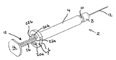
본 발명에 따른 주사기 (2)가 도 1, 도 2 및 도 3에 제시되어 있다. 주사기 (2)는 실린더를 내부에서 한정하는 배럴 본체(barrel body, 4)를 포함한다. 배럴 (4)의 후방에는 칼라 (6)가 위치되고, 배럴 (4)의 대향 단부, 즉 전방에는 배출 통로를 내부에서 한정하는 배출 단부 (10)가 있다. 배럴 (4)의 배출 단부 (10)에는 피하주사 바늘 (12)의 연결 칼라 (8)가 고정된다.A
당업자는 피하주사 바늘 연결 칼라 (8)가 배럴의 배출 단부 (10)와의 간단한 마찰 끼워맞춤부일 수 있거나 배럴의 배출 단부 (10)에 부착될 수 있거나 루어-락(Luer-Lok) 칼라와 같은 로킹 칼라일 수 있음을 인식할 것이다. 주사기 배럴에 대한 피하주사 바늘의 연결은 당업계에 잘 알려져 있으며, 본원에서는 상세히 기술되지 않을 것이다.Those skilled in the art will appreciate that the hypodermic
플런저 (15)는 칼라 (6)에 활주가능하게 커플링되고, 플런저는 배럴 실린더 내의 피스톤 (도시되지 않음) 및 십자형 단면의 긴 샤프트 (14)를 포함하며, 샤프트는 피스톤에 대한 샤프트 (14)의 대향 단부에서 플랜지(flange) (16)로 종료되어, 플랜지 (16)의 후방 대면 표면이 플런저 (15)를 위한 푸시 버튼을 형성하게 한다.The
칼라 (6)의 후방 대면 표면은 한 쌍의 대향하는 돌출부들 (20a, 20b)이 축방향으로 돌출하여 나오는 실질적으로 평평한 칼라 기부 표면 (7)을 한정한다.The rear facing surface of the
2개의 대향하는 돌출부들 (20a, 20b)은 배럴의 종축을 중심으로 동심으로 형성된 가상 원의 2개의 대향하는 원호들을 규정하고, 또한 가상 원의 대향하는 원호들의 형태인 한 쌍의 대향하는 아치형 간극들 (22a, 22b)을 돌출부들 사이에서 한정하여, 돌출부들 (20a, 20b) 및 간극들 (22a, 22b)이 함께 가상 원의 원주를 규정하도록 한다. 돌출부 (20a, 20b)에 의해 규정되는 원호들은 돌출부들 (20a, 20b) 사이의 간극들 (22a, 22b)에 의해 한정되는 원호들보다 더 짧다.The two opposing protrusions 20a, 20b define two opposing arcs of an imaginary circle formed concentrically about the longitudinal axis of the barrel, and also a pair of opposing arcuate gaps in the form of opposing arcs of the imaginary circle. The fields 22a, 22b are defined between the protrusions, such that the protrusions 20a, 20b and the gaps 22a, 22b together define the circumference of the virtual circle. The arcs defined by the protrusions 20a and 20b are shorter than the arcs defined by the gaps 22a and 22b between the protrusions 20a and 20b.
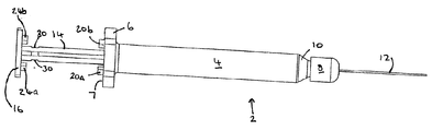
도 2는 플랜지 (16)와 샤프트 (14)의 전방 대면 부품들의 상세도를 제시한다.2 shows a detailed view of the front facing parts of the
플랜지 (16)는 한 쌍의 대향하는 아치형 돌출부들 (24a, 24b)이 축방향으로 돌출하여 나오는 실질적으로 평평한 전방 대면 기부 표면 (17)을 한정한다. 플랜지 돌출부들 (24a, 24b)은 칼라 돌출부들 (20a, 20b)과 실질적으로 동일한 배열로 배열된다. 따라서, 플랜지 돌출부들 (24a, 24b)은 그들 사이에서 아치형 간극들 (26a, 26b)을 한정하고, 플랜지 돌출부들 (24a, 24b) 및 이들 사이에 한정된 간극들 (26a, 26b)은 함께 샤프트 (14)의 종축을 중심으로 동심으로 배열된 가상 원의 원주를 규정한다.The
칼라 (6) 상의 돌출부들 (20a, 20b) 및 간극들 (22a, 22b)의 배열과 마찬가지로, 플랜지 (16)의 기부 표면 (17)으로부터의 돌출부들 (24a, 24b)에 의해 규정되는 원호는 돌출부들 (24a, 24b) 사이의 간극들 (26a, 26b)에 의해 한정되는 원호보다 더 짧다.Like the arrangement of the protrusions 20a, 20b and the gaps 22a, 22b on the
피스톤이 배출 단부 (10)로부터 이격되어 결국 도면들에 제시된 바와 같이 플랜지 (16)가 칼라 (6)로부터 이격될 때, 칼라 돌출부들 (20a, 20b)은 플랜지 돌출부들 (24a, 24b)로부터 이격된다. 이러한 방식으로 이격될 때, 칼라 돌출부들 (20a, 20b)은 플랜지 돌출부들 (24a, 24b)과 축방향으로 정렬된다.When the piston is spaced from the
십자형 샤프트 (14)는 칼라 (6)에 형성된 상호보완적인 형상의 (즉, 십자 형상의) 관통 구멍 내에 활주가능하게 위치된다. 이는 두 쌍의 돌출부들 (20a, 20b, 24a, 24b)이 이격되고 축방으로 정렬될 때 샤프트 (14) 및 플랜지 (16)가 칼라 및 배럴에 대해 일정한 배향으로 유지되는 것을 보장한다.The
샤프트 (14)의 각각의 아암은 노치 (30)를 포함하되 모든 4개의 노치들 (30)이 플랜지 (16)의 기부 표면 (17)으로부터 균등하게 이격되도록 포함한다. 노치들은 칼라 돌출부들 (20a, 20b)이 플랜지 돌출부들 (24a, 24b)과 접촉할 때 칼라 (6)의 몸체와 중첩하도록 구성된다. 노치들 (30)이 칼라 (6)의 몸체와 중첩할 때, 샤프트 (14)는 칼라 (6)로부터 맞닿음 해제되어 그의 종축을 중심으로 칼라 (6)에 대해 회전하게 된다.Each arm of the
그의 종축을 중심으로 한 90o 회전은 십자형 샤프트 (14)를 칼라 (6)를 통한 십자 형상의 관통 구멍과 재정렬시킨다. 게다가, 칼라 돌출부들 (20a, 20b)은 플랜지 간극들 (26a, 26b)과 축방향으로 정렬되게 되고, 플랜지 돌출부들 (24a, 24b)은 칼라 간극들 (22a, 22b)과 축방향으로 정렬되게 된다. 간극들 (22a, 22b, 26a, 26b)이 대응하는 돌출부들 (20a, 20b, 24a, 24b)보다 더 크기 때문에, 돌출부들 (20a, 20b, 24a, 24b)은 이러한 구성에서 축방향으로 서로를 지나 활주할 수 있다.A 90 ° rotation about its longitudinal axis aligns the
사용시, 돌출부들 (20a, 20b, 24a, 24b)이 축방향으로 정렬될 때 플랜지 (16) 및 이에 따른 피스톤을 후방으로 잡아당김으로써 배럴 (4) 내의 실린더가 유체, 예를 들어 액체 제형의 의약으로 충전된다.In use, the cylinders in the barrel 4 allow fluid, eg liquid formulation, by pulling back the
그리고 나서, 푸시 버튼을 눌러 플랜지 (16), 샤프트 (14) 및 피스톤을 배럴 (4)의 배출 단부 (10)를 향해 전방으로 축방향으로 활주시킴으로써 주사기가 프라이밍된다. 이는 배럴 (4)의 실린더 및 바늘 (12)로부터 모든 공기를 배출시키는 효과를 갖는다.The syringe is then primed by pressing the push button to slide the
프라이밍 단계는 플랜지 돌출부들 (24a, 24b)이 칼라 돌출부들 (20a, 20b)과 접촉할 때까지 계속되는데, 이 시점에서 노치들 (30)은 칼라 (6)의 몸체와 중첩한다. 그리고 나서, 플랜지는 90o에 걸쳐 회전되는데, 그 결과 돌출부들 (20a, 20b, 24a, 24b)이 대응하는 간극들 (22a, 22b, 26a, 26b)과 축방향으로 정렬된다. 그리고 나서, 푸시 버튼이 전방으로 한번 더 가압되어 예정된 용량의 유체를 전달한다. 이러한 전달 단계는 플랜지 돌출부들 (24a, 24b)이 칼라 기부 표면 (7)과 접촉할 때까지 및/또는 칼라 돌출부들 (20a, 20b)이 플랜지 기부 표면 (17)과 접촉할 때까지 계속된다.The priming step continues until the
전달 단계 동안 전달되는 용량의 체적은 배럴의 실린더의 단면적과 돌출부들 (20a, 20b, 24a, 24b) 중 최장 돌출부의 길이를 곱함으로써 계산되는데, 여기서 돌출부의 길이는 관련 돌출부가 각자의 기부 표면으로부터 연장되는 거리로서 정의된다. 따라서, 전달되는 체적은 배럴 (4)의 실린더의 단면적을 변화시킴으로써 또는 돌출부의 길이를 변화시킴으로써 또는 둘 모두에 의해 변화될 수 있다.The volume of capacity delivered during the delivery step is calculated by multiplying the cross-sectional area of the cylinder of the barrel by the length of the longest of the
전술된 주사기에 대한 시험을 다음과 같이 수행하였다:The test on the aforementioned syringe was performed as follows:
시험 장치tester
주사기 플런저 및 칼라를 샘플 1㎖ 주사기 배럴로 조립하였다. 바늘을 주사기 배럴의 배출 단부에 끼웠다.The syringe plunger and collar were assembled into a sample 1 ml syringe barrel. The needle was inserted into the discharge end of the syringe barrel.
준비 및 측정Preparation and Measurement
주사기를 공칭 체적의 RO/DI 물로 충전하였고, 수직으로 유지하였으며, 공기 기포를 배출하도록 가볍게 두드렸고, 제1 멈춤부까지 프라이밍시켰다. 깨끗한 에펜도르프 튜브(Eppendorf Tube)를 분석용 저울 상에서 중량을 재었다. 투여를 허용하도록 플런저를 제1 축방향 배향으로부터 제2 축방향 배향으로 회전시켰고, 플런저를 제2 멈춤부까지 눌러 용량을 바이알 내로 배출시켰다.The syringe was filled with a nominal volume of RO / DI water, held vertically, tapped to release air bubbles and primed to the first stop. Clean Eppendorf Tubes were weighed on the analytical balance. The plunger was rotated from the first axial orientation to the second axial orientation to allow administration, and the plunger was pressed to the second stop to discharge the dose into the vial.
그리고 나서, 바이알을 폐쇄하고 칭량하였다.The vial was then closed and weighed.
주사기를 재사용하되 깨끗한 바이알을 취하여 시험을 반복하였다.The syringe was reused but the test was repeated with a clean vial taken.
계산Calculation
바이알의 중량 차이로부터 용량의 질량을 계산하였다.The mass of the dose was calculated from the weight difference of the vial.
질량을 밀도로 나눔으로써 용량의 체적을 계산하였다.The volume of the capacity was calculated by dividing the mass by the density.
21℃ 및 42%RH의 실험실 조건에서 밀도 = 998.022 kg/m3 Density at laboratory conditions of 21 ° C and 42% RH = 998.022 kg / m 3
장치Device
사토리우스(Sartorius) ME235S-OCE 분석용 저울 (소수점 아래 5 자릿수/1 g)Sartorius ME235S-OCE Analytical Balance (5 digits below the decimal point / 1 g)
300 ㎕ 에펜도르프 튜브300 μl eppendorf tubes
주사기 장치Syringe device
결과result

본 시험에서 프로토타입에 의해 전달된 용량은 44.4±3.8 ㎕, 즉 40.8 내지 48.4 ㎕의 범위이다.The dose delivered by the prototype in this test ranged from 44.4 ± 3.8 μl, ie 40.8 to 48.4 μl.
주사기는 허용 한계와 연관된 ±7.5 ㎕의 허용오차 내에 있는 ±3.8 ㎕의 허용오차 내에서 잘 조절된 용량을 전달하였다.The syringe delivered a well controlled dose within a tolerance of ± 3.8 μl that was within a tolerance of ± 7.5 μl associated with the tolerance.
Claims (15)
배출 통로를 한정하는 배출 단부를 포함하는 배럴(barrel); 및
배럴 내부에 배치되는 플런저를 포함하고,
플런저는 플런저와 배출 단부가 배럴 내부에서 가변 체적 챔버를 한정하도록, 및 플런저가 유체를 챔버로부터 배출 통로를 통해 변위시킬 수 있도록 배럴 내부에서 이동하도록 구성되며,
주사기는 주사기의 종축을 중심으로 회전하도록 구성되고 배럴의 배출 단부에 대한 제1 축방향 배향을 갖는 회전 요소를 포함하고,
회전 요소의 제1 배향에서 플런저의 축방향 이동을 제한하도록 구성된 제1 멈춤부가 플런저 및/또는 배럴 상에 제공되며,
회전 요소는 배럴의 배출 단부에 대한 제2 축방향 배향을 가지며, 여기서 제1 멈춤부가 맞닿음 해제되고 플런저의 이동이 제2 멈춤부까지 허용되는 것인, 주사기.A syringe for dispensing fluid,
A barrel including a discharge end defining a discharge passage; And
A plunger disposed inside the barrel,
The plunger is configured to move inside the barrel such that the plunger and the discharge end define a variable volume chamber inside the barrel, and the plunger can displace fluid from the chamber through the discharge passageway,
The syringe is configured to rotate about the longitudinal axis of the syringe and includes a rotating element having a first axial orientation with respect to the discharge end of the barrel,
A first stop provided on the plunger and / or barrel, configured to limit the axial movement of the plunger in the first orientation of the rotating element,
The rotating element has a second axial orientation with respect to the discharge end of the barrel, wherein the first stop is disengaged and movement of the plunger is allowed to the second stop.
배럴의 일 단부와 결합하도록 구성된 칼라; 및
배럴 내부에 위치되도록 구성된 피스톤, 피스톤으로부터 연장되는 긴 샤프트, 및 피스톤에 대향한 상기 샤프트의 단부에서의 푸시 버튼을 포함하는 플런저를 포함하고,
칼라는 긴 샤프트에 활주가능하게 커플링되고, 플런저는 칼라에 대한 제1 축방향 배향을 가지며, 제1 배향에서 플런저의 축방향 이동을 제한하도록 구성된 제1 멈춤부가 플런저 및/또는 칼라 상에 제공되고, 플런저는 제1 멈춤부가 맞닿음 해제되고 플런저의 이동이 제2 멈춤부까지 허용되는, 칼라에 대한 제2 축방향 배향을 갖는 것인, 플런저 조립체.Plunger assembly for use in syringe barrel,
A collar configured to engage one end of the barrel; And
A plunger comprising a piston configured to be positioned inside the barrel, an elongated shaft extending from the piston, and a push button at the end of the shaft opposite the piston,
The collar is slidably coupled to the elongate shaft, the plunger has a first axial orientation with respect to the collar, and a first stop provided on the plunger and / or collar configured to limit the axial movement of the plunger in the first orientation. Wherein the plunger has a second axial orientation with respect to the collar such that the first stop is abutted and movement of the plunger is allowed to the second stop.
Applications Claiming Priority (2)
| Application Number | Priority Date | Filing Date | Title |
|---|---|---|---|
| EP09176607 | 2009-11-20 | ||
| EP09176607.1 | 2009-11-20 |
Publications (1)
| Publication Number | Publication Date |
|---|---|
| KR20120112468A true KR20120112468A (en) | 2012-10-11 |
Family
ID=42060899
Family Applications (1)
| Application Number | Title | Priority Date | Filing Date |
|---|---|---|---|
| KR1020127015839A KR20120112468A (en) | 2009-11-20 | 2010-11-19 | Syringe |
Country Status (11)
| Country | Link |
|---|---|
| US (1) | US20120226240A1 (en) |
| EP (1) | EP2501420A1 (en) |
| JP (1) | JP5801314B2 (en) |
| KR (1) | KR20120112468A (en) |
| CN (1) | CN102665804B (en) |
| AU (1) | AU2010320885B2 (en) |
| BR (1) | BR112012011973A2 (en) |
| CA (1) | CA2781483A1 (en) |
| MX (1) | MX2012005817A (en) |
| RU (1) | RU2012125349A (en) |
| WO (1) | WO2011061313A1 (en) |
Families Citing this family (11)
| Publication number | Priority date | Publication date | Assignee | Title |
|---|---|---|---|---|
| US8323249B2 (en) | 2009-08-14 | 2012-12-04 | The Regents Of The University Of Michigan | Integrated vascular delivery system |
| WO2011146769A2 (en) | 2010-05-19 | 2011-11-24 | Tangent Medical Technologies Llc | Integrated vascular delivery system |
| US8814833B2 (en) | 2010-05-19 | 2014-08-26 | Tangent Medical Technologies Llc | Safety needle system operable with a medical device |
| WO2015119940A1 (en) | 2014-02-04 | 2015-08-13 | Icu Medical, Inc. | Self-priming systems and methods |
| JP6165655B2 (en) * | 2014-03-13 | 2017-07-19 | 株式会社吉野工業所 | Metered syringe type ejector |
| CN106573105B (en) * | 2014-07-24 | 2019-10-18 | 泰利福医疗公司 | Dose dispensing syringe |
| WO2018203225A1 (en) | 2017-05-05 | 2018-11-08 | Novartis Ag | A syringe comprising a collapsible plunger |
| US20200188590A1 (en) * | 2017-06-08 | 2020-06-18 | Novartis Ag | Filling adapter and injection solution transferring system |
| CN111491680B (en) | 2017-12-13 | 2023-08-29 | 里珍纳龙药品有限公司 | Device and method for accurate dose delivery |
| WO2019123487A1 (en) * | 2017-12-19 | 2019-06-27 | Matex Lab S.P.A. | Syringe assembly |
| MA54325A (en) | 2019-06-05 | 2022-05-11 | Regeneron Pharma | DEVICES AND METHODS FOR ACCURATE DOSE DELIVERY |
Family Cites Families (16)
| Publication number | Priority date | Publication date | Assignee | Title |
|---|---|---|---|---|
| US2607343A (en) * | 1951-05-02 | 1952-08-19 | American Viscose Corp | Syringe pipette |
| FR1412547A (en) * | 1964-08-20 | 1965-10-01 | Comptoir De Diffusion De Produ | Injection syringe |
| GB1105367A (en) * | 1965-06-11 | 1968-03-06 | Edward Philip Marbach | Proportioning syringe |
| GB1230522A (en) * | 1968-05-20 | 1971-05-05 | ||
| US3934586A (en) | 1975-01-22 | 1976-01-27 | Easton Fred H | Non-refillable multiple dosage syringe |
| FR2536285B1 (en) * | 1982-11-18 | 1986-03-07 | Buttigieg Charles | IMPROVED SYRINGE WITH CONTROLLABLE LOCKING POSITION |
| DK172984D0 (en) * | 1984-03-30 | 1984-03-30 | Novo Industri As | DISPENSER |
| JPS6130697U (en) * | 1984-07-26 | 1986-02-24 | 三菱鉛筆株式会社 | syringe |
| JPH0617746U (en) * | 1992-08-11 | 1994-03-08 | 秀男 並木 | Syringe |
| GB9316692D0 (en) * | 1993-08-11 | 1993-09-29 | Smithkline Beecham Plc | Novel device |
| US5485853A (en) * | 1994-04-28 | 1996-01-23 | Stubbs; George | Apparatus for withdrawing fluid or tissue from a patient's body |
| IL114371A0 (en) * | 1995-06-28 | 1995-10-31 | Popov Sergei | A dose setting syringe |
| CA2345015A1 (en) * | 1998-09-30 | 2000-04-06 | Eric S. Mathias | Exact dose dispenser device assembly |
| JP2004500201A (en) | 2000-02-23 | 2004-01-08 | アボット・ラボラトリーズ | Syringe and syringe system for selectively delivering a controlled amount of a therapeutic substance |
| WO2003004080A1 (en) * | 2001-07-05 | 2003-01-16 | Akzo Nobel N.V. | Syringe for the injection of a medicament |
| JP2004049726A (en) * | 2002-07-23 | 2004-02-19 | Shimizu Pharmaceutical Co Ltd | Syringe |
-
2010
- 2010-11-19 CA CA2781483A patent/CA2781483A1/en not_active Abandoned
- 2010-11-19 KR KR1020127015839A patent/KR20120112468A/en not_active Application Discontinuation
- 2010-11-19 AU AU2010320885A patent/AU2010320885B2/en not_active Ceased
- 2010-11-19 EP EP10785390A patent/EP2501420A1/en not_active Withdrawn
- 2010-11-19 RU RU2012125349/14A patent/RU2012125349A/en not_active Application Discontinuation
- 2010-11-19 JP JP2012539345A patent/JP5801314B2/en not_active Expired - Fee Related
- 2010-11-19 WO PCT/EP2010/067869 patent/WO2011061313A1/en active Application Filing
- 2010-11-19 CN CN201080052421.9A patent/CN102665804B/en not_active Expired - Fee Related
- 2010-11-19 MX MX2012005817A patent/MX2012005817A/en unknown
- 2010-11-19 BR BR112012011973A patent/BR112012011973A2/en not_active IP Right Cessation
- 2010-11-19 US US13/510,213 patent/US20120226240A1/en not_active Abandoned
Also Published As
| Publication number | Publication date |
|---|---|
| MX2012005817A (en) | 2012-06-12 |
| EP2501420A1 (en) | 2012-09-26 |
| JP2013511309A (en) | 2013-04-04 |
| RU2012125349A (en) | 2013-12-27 |
| US20120226240A1 (en) | 2012-09-06 |
| BR112012011973A2 (en) | 2016-05-10 |
| CA2781483A1 (en) | 2011-05-26 |
| WO2011061313A1 (en) | 2011-05-26 |
| AU2010320885A1 (en) | 2012-05-24 |
| CN102665804B (en) | 2014-11-12 |
| AU2010320885B2 (en) | 2013-03-14 |
| CN102665804A (en) | 2012-09-12 |
| WO2011061313A9 (en) | 2012-07-19 |
| JP5801314B2 (en) | 2015-10-28 |
Similar Documents
| Publication | Publication Date | Title |
|---|---|---|
| KR20120112468A (en) | Syringe | |
| WO2011073176A1 (en) | Syringe | |
| AU2007207309C1 (en) | Injection device with secured dosing button | |
| WO2011073174A1 (en) | Syringe | |
| JP2013512707A (en) | Drug delivery device | |
| EP3261695B1 (en) | Dose divider syringe | |
| JP6968144B2 (en) | Drug delivery device with regulator | |
| US20160296703A1 (en) | A Pharmaceutical Component-Mixing Delivery Assembly | |
| EP3077026A1 (en) | Dose divider syringe | |
| CA2996197C (en) | Dose divider syringe | |
| CN110461392B (en) | Dial gear train for torsion spring assisted wind-up injection device | |
| US20190336686A1 (en) | Plunger sub-assembly for a prefilled medicament injector, a prefilled medicament injector and method for assembling a prefilled medical injector | |
| CN115916297A (en) | Drug delivery device and method for determining a dose | |
| CN117500546A (en) | Drug delivery device and method for operating a drug delivery device |
Legal Events
| Date | Code | Title | Description |
|---|---|---|---|
| A201 | Request for examination | ||
| WITB | Written withdrawal of application |