KR20120109546A - Method for transmitting channel state information in wireless access system - Google Patents
Method for transmitting channel state information in wireless access system Download PDFInfo
- Publication number
- KR20120109546A KR20120109546A KR1020127017739A KR20127017739A KR20120109546A KR 20120109546 A KR20120109546 A KR 20120109546A KR 1020127017739 A KR1020127017739 A KR 1020127017739A KR 20127017739 A KR20127017739 A KR 20127017739A KR 20120109546 A KR20120109546 A KR 20120109546A
- Authority
- KR
- South Korea
- Prior art keywords
- csi
- type
- cqi
- base station
- pmi
- Prior art date
Links
Images


Classifications
-
- H—ELECTRICITY
- H04—ELECTRIC COMMUNICATION TECHNIQUE
- H04L—TRANSMISSION OF DIGITAL INFORMATION, e.g. TELEGRAPHIC COMMUNICATION
- H04L1/00—Arrangements for detecting or preventing errors in the information received
- H04L1/0001—Systems modifying transmission characteristics according to link quality, e.g. power backoff
- H04L1/0023—Systems modifying transmission characteristics according to link quality, e.g. power backoff characterised by the signalling
- H04L1/0026—Transmission of channel quality indication
-
- H—ELECTRICITY
- H04—ELECTRIC COMMUNICATION TECHNIQUE
- H04J—MULTIPLEX COMMUNICATION
- H04J11/00—Orthogonal multiplex systems, e.g. using WALSH codes
- H04J11/0023—Interference mitigation or co-ordination
-
- H—ELECTRICITY
- H04—ELECTRIC COMMUNICATION TECHNIQUE
- H04B—TRANSMISSION
- H04B7/00—Radio transmission systems, i.e. using radiation field
- H04B7/02—Diversity systems; Multi-antenna system, i.e. transmission or reception using multiple antennas
- H04B7/04—Diversity systems; Multi-antenna system, i.e. transmission or reception using multiple antennas using two or more spaced independent antennas
- H04B7/06—Diversity systems; Multi-antenna system, i.e. transmission or reception using multiple antennas using two or more spaced independent antennas at the transmitting station
- H04B7/0613—Diversity systems; Multi-antenna system, i.e. transmission or reception using multiple antennas using two or more spaced independent antennas at the transmitting station using simultaneous transmission
- H04B7/0615—Diversity systems; Multi-antenna system, i.e. transmission or reception using multiple antennas using two or more spaced independent antennas at the transmitting station using simultaneous transmission of weighted versions of same signal
- H04B7/0619—Diversity systems; Multi-antenna system, i.e. transmission or reception using multiple antennas using two or more spaced independent antennas at the transmitting station using simultaneous transmission of weighted versions of same signal using feedback from receiving side
- H04B7/0621—Feedback content
- H04B7/0626—Channel coefficients, e.g. channel state information [CSI]
-
- H—ELECTRICITY
- H04—ELECTRIC COMMUNICATION TECHNIQUE
- H04W—WIRELESS COMMUNICATION NETWORKS
- H04W72/00—Local resource management
- H04W72/20—Control channels or signalling for resource management
- H04W72/21—Control channels or signalling for resource management in the uplink direction of a wireless link, i.e. towards the network
-
- H—ELECTRICITY
- H04—ELECTRIC COMMUNICATION TECHNIQUE
- H04L—TRANSMISSION OF DIGITAL INFORMATION, e.g. TELEGRAPHIC COMMUNICATION
- H04L5/00—Arrangements affording multiple use of the transmission path
- H04L5/0001—Arrangements for dividing the transmission path
- H04L5/0003—Two-dimensional division
- H04L5/0005—Time-frequency
- H04L5/0007—Time-frequency the frequencies being orthogonal, e.g. OFDM(A), DMT
- H04L5/001—Time-frequency the frequencies being orthogonal, e.g. OFDM(A), DMT the frequencies being arranged in component carriers
-
- H—ELECTRICITY
- H04—ELECTRIC COMMUNICATION TECHNIQUE
- H04L—TRANSMISSION OF DIGITAL INFORMATION, e.g. TELEGRAPHIC COMMUNICATION
- H04L5/00—Arrangements affording multiple use of the transmission path
- H04L5/003—Arrangements for allocating sub-channels of the transmission path
- H04L5/0053—Allocation of signaling, i.e. of overhead other than pilot signals
- H04L5/0055—Physical resource allocation for ACK/NACK
-
- H—ELECTRICITY
- H04—ELECTRIC COMMUNICATION TECHNIQUE
- H04L—TRANSMISSION OF DIGITAL INFORMATION, e.g. TELEGRAPHIC COMMUNICATION
- H04L5/00—Arrangements affording multiple use of the transmission path
- H04L5/003—Arrangements for allocating sub-channels of the transmission path
- H04L5/0053—Allocation of signaling, i.e. of overhead other than pilot signals
- H04L5/0057—Physical resource allocation for CQI
-
- H—ELECTRICITY
- H04—ELECTRIC COMMUNICATION TECHNIQUE
- H04W—WIRELESS COMMUNICATION NETWORKS
- H04W24/00—Supervisory, monitoring or testing arrangements
- H04W24/10—Scheduling measurement reports ; Arrangements for measurement reports
-
- H—ELECTRICITY
- H04—ELECTRIC COMMUNICATION TECHNIQUE
- H04W—WIRELESS COMMUNICATION NETWORKS
- H04W72/00—Local resource management
- H04W72/04—Wireless resource allocation
- H04W72/044—Wireless resource allocation based on the type of the allocated resource
- H04W72/0453—Resources in frequency domain, e.g. a carrier in FDMA
-
- H—ELECTRICITY
- H04—ELECTRIC COMMUNICATION TECHNIQUE
- H04J—MULTIPLEX COMMUNICATION
- H04J2211/00—Orthogonal indexing scheme relating to orthogonal multiplex systems
- H04J2211/003—Orthogonal indexing scheme relating to orthogonal multiplex systems within particular systems or standards
- H04J2211/005—Long term evolution [LTE]
-
- H—ELECTRICITY
- H04—ELECTRIC COMMUNICATION TECHNIQUE
- H04J—MULTIPLEX COMMUNICATION
- H04J2211/00—Orthogonal indexing scheme relating to orthogonal multiplex systems
- H04J2211/003—Orthogonal indexing scheme relating to orthogonal multiplex systems within particular systems or standards
- H04J2211/006—Single carrier frequency division multiple access [SC FDMA]
Landscapes
- Engineering & Computer Science (AREA)
- Signal Processing (AREA)
- Computer Networks & Wireless Communication (AREA)
- Quality & Reliability (AREA)
- Mobile Radio Communication Systems (AREA)
Abstract
Description
본 발명은 무선 접속 시스템에 관한 것으로서, 캐리어 결합 환경에서 하나 이상의 서빙셀에 대한 채널상태정보를 전송하는 다양한 방법들 및 이를 지원하는 장치에 관한 것이다. 또한, PHICH 할당방법들에 대해서 개시한다.BACKGROUND OF THE
일반적인 무선 접속 시스템에서는 상향링크와 하향링크 간의 대역폭은 서로 다르게 설정되더라도 주로 하나의 반송파(carrier)만을 고려하고 있다. 예를 들어, 단일 반송파를 기반으로, 상향링크와 하향링크를 구성하는 반송파의 수가 각각 1개이고, 상향링크의 대역폭과 하향링크의 대역폭이 일반적으로 서로 대칭적인 무선 통신 시스템이 제공될 수 있다.In a typical wireless access system, even if the bandwidth between uplink and downlink is configured differently, only one carrier is mainly considered. For example, based on a single carrier, a number of carriers constituting uplink and downlink may be one each, and a wireless communication system in which uplink bandwidth and downlink bandwidth are generally symmetrical to each other may be provided.
ITU(International Telecommunication Union)에서는 IMT-Advanced의 후보기술이 기존의 무선 통신 시스템에 비하여 확장된 대역폭을 지원할 것을 요구하고 있다. 그러나, 전세계적으로 일부 지역을 제외하고는 큰 대역폭의 주파수 할당이 용이하지 않다. 따라서, 조각난 작은 대역을 효율적으로 사용하기 위한 기술로 주파수 영역에서 물리적으로 다수 개의 밴드를 묶어 논리적으로 큰 대역의 밴드를 사용하는 것과 같은 효과를 내도록 하기 위한 반송파 집성(Carrier Aggregation; 대역폭 집성(Bandwidth Aggregation) 또는 스펙트럼 집성(Spectrum Aggregation)이라고도 함) 기술이 개발되고 있다.The International Telecommunication Union (ITU) requires that IMT-Advanced candidate technology support extended bandwidth as compared to existing wireless communication systems. However, frequency allocation of large bandwidths is not easy except in some regions of the world. Therefore, carrier aggregation (Bandwidth Aggregation) for efficient use of fragmented small bands to achieve the same effect as combining multiple bands physically in the frequency domain and using bands of logically large bands. ), Or also called Spectrum Aggregation, is being developed.
반송파 집성은 증가되는 수율(throughput)을 지원하고, 광대역 RF 소자의 도입으로 인한 비용 증가를 방지하고, 기존 시스템과의 호환성을 보장하기 위해 도입되는 것이다. 반송파 집성이란 기존의 무선 접속 시스템(LTE-A 시스템의 경우에는 LTE 시스템, 또는 IEEE 802.16m 시스템의 경우에는 IEEE 802.16e 시스템)에서 정의되는 대역폭 단위의 반송파들의 복수 개의 묶음을 통하여 단말과 기지국 간에 데이터를 교환할 수 있도록 하는 기술이다.Carrier aggregation is introduced to support increased throughput, to prevent cost increases due to the introduction of wideband RF devices, and to ensure compatibility with existing systems. Carrier aggregation refers to data between a terminal and a base station through a plurality of bundles of carriers in a bandwidth unit defined in a conventional radio access system (LTE system in case of LTE-A system, or IEEE 802.16e system in case of IEEE 802.16m system). It is a technology that can be exchanged.
여기서, 기존의 무선 통신 시스템에서 정의되는 대역폭 단위의 반송파를 컴포넌트 캐리어(CC: Component Carrier)라고 칭할 수 있다. 예를 들어, 반송파 집성 기술은 하나의 컴포넌트 캐리어가 5MHz, 10MHz 또는 20MHz의 대역폭을 지원하더라도 최대 5 개의 컴포넌트 캐리어를 묶어 최대 100MHz까지의 시스템 대역폭을 지원하는 기술을 포함할 수 있다.Here, the carrier of the bandwidth unit defined in the existing wireless communication system may be referred to as a component carrier (CC). For example, the carrier aggregation technology may include a technology that supports a system bandwidth of up to 5 MHz by tying up to 5 component carriers even though one component carrier supports a bandwidth of 5 MHz, 10 MHz, or 20 MHz.
반송파 집성 기술을 이용하는 경우에, 여러 개의 상향링크/하향링크 구성반송파를 통해 데이터를 동시에 송수신할 수 있다. 따라서, 단말은 모든 컴포넌트 캐리어를 모니터링하고 측정할 수 있다.In case of using carrier aggregation technology, data may be simultaneously transmitted and received through multiple uplink / downlink component carriers. Thus, the terminal can monitor and measure all component carriers.
단말의 상향링크 전송시, 전력 증폭기(power amplifier)의 왜곡을 줄이기 위해 상향링크 전송 신호에 대하여 단일 캐리어(single-carrier) 특성을 유지시키는 것이 요구된다. 이를 위해 복수의 PUCCH가 동일한 서브프레임을 통해 전송되어야 할 경우, 상향링크 전송 신호의 단일 캐리어 특성을 유지시키기 위한 단말의 동작(UE behavior)을 정의하는 것이 필요하다.In the uplink transmission of the terminal, it is required to maintain a single-carrier characteristic for the uplink transmission signal in order to reduce distortion of the power amplifier. For this purpose, when a plurality of PUCCHs are to be transmitted through the same subframe, it is necessary to define a UE behavior for maintaining a single carrier characteristic of an uplink transmission signal.
하나의 서브프레임에서 단말은 하나의 서빙 셀에 대한 제어 정보를 전송해야한다. 이때, 동일한 서브프레임을 통해 하나 이상의 서빙 셀에 대한 채널상태정보(CSI)가 전송되는 경우에, 단말의 CSI 보고 동작을 정의하는 것이 필요하다.In one subframe, the UE should transmit control information for one serving cell. In this case, when channel state information (CSI) of one or more serving cells is transmitted through the same subframe, it is necessary to define a CSI reporting operation of the UE.
따라서, 본 발명의 목적은 멀티캐리어 결합 환경에서 복수의 서빙 셀에 대한 CSI 전송을 위한 단말의 상향링크 동작을 정의하는 것이다.Accordingly, an object of the present invention is to define an uplink operation of a terminal for CSI transmission for a plurality of serving cells in a multicarrier combining environment.
본 발명의 다른 목적은 특정 서브프레임에서 복수의 PUCCH를 통한 복수의 서빙 셀에 대한 CSI 전송이 동시에 요구될 경우, 하나의 PUCCH를 통해 하나의 제어정보(즉, CSI)를 전송할 수 있는 방법을 제공하는 것이다.Another object of the present invention is to provide a method for transmitting one control information (ie, CSI) through one PUCCH when CSI transmission for a plurality of serving cells through a plurality of PUCCHs is simultaneously requested in a specific subframe. It is.
본 발명의 또 다른 목적은 복수의 CSI들 중에서 특정 CSI만을 전송할 수 있도록 우선순위에 따른 CSI 드롭(Dropping) 방법을 제공하는 것이다. 예를 들어, 단말이 셀 타입, CSI 전송 주기 및/또는 CSI 타입에 따라 특정 CSI를 드롭하는 방법을 제안한다.Another object of the present invention is to provide a CSI dropping method according to priority so that only a specific CSI can be transmitted among a plurality of CSIs. For example, the terminal proposes a method of dropping a specific CSI according to a cell type, a CSI transmission period, and / or a CSI type.
본 발명에서 이루고자 하는 기술적 목적들은 이상에서 언급한 사항들로 제한되지 않으며, 언급하지 않은 또 다른 기술적 과제들은 이하 설명할 본 발명의 실시예들로부터 본 발명이 속하는 기술분야에서 통상의 지식을 가진 자에 의해 고려될 수 있다.Technical objects to be achieved in the present invention are not limited to the above-mentioned matters, and other technical problems which are not mentioned are those skilled in the art from the embodiments of the present invention to be described below. Can be considered.
상기의 기술적 과제를 해결하기 위해, 본 발명은 캐리어 결합 환경에서 하나 이상의 서빙셀에 대한 채널상태정보를 전송하는 다양한 방법들 및 이를 지원하는 장치들을 개시한다.In order to solve the above technical problem, the present invention discloses various methods and apparatuses for supporting the channel state information for one or more serving cells in a carrier coupling environment.
본 발명의 일 양태로서 캐리어 결합을 지원하는 무선 접속 시스템에서 채널상태정보(CSI)를 보고하는 방법은, 단말이 기지국으로부터 하나 이상의 서빙 셀에 대한 CSI 보고 모드와 관련된 정보를 수신하는 단계와 단말이 CSI 보고 모드를 고려하여 하나 이상의 서빙 셀에 대한 채널상태정보(CSI)를 기지국으로 보고하는 단계를 포함할 수 있다. 이때, 제 1 서빙셀에 대한 제 1 타입 CSI와 제 2 서빙셀에 대한 제 2 타입 CSI가 동일 서브프레임에서 전송되는 경우에는, 단말은 CSI 보고 모드와 관련된 CSI 보고 타입의 우선순위에 따라 하나의 서빙셀에 대한 CSI만을 기지국에 보고할 수 있다.In one aspect of the present invention, a method for reporting channel state information (CSI) in a wireless access system supporting carrier combining includes: receiving, by a terminal, information related to a CSI reporting mode for at least one serving cell from a base station; Reporting channel state information (CSI) for one or more serving cells to the base station in consideration of the CSI reporting mode. In this case, when the first type CSI for the first serving cell and the second type CSI for the second serving cell are transmitted in the same subframe, the UE may select one according to the priority of the CSI report type related to the CSI reporting mode. Only the CSI for the serving cell may be reported to the base station.
본 발명의 다른 양태로서 캐리어 결합을 지원하는 무선 접속 시스템에서 채널상태정보(CSI)를 수신하는 방법은, 기지국에서 단말로 하나 이상의 서빙 셀에 대한 CSI 보고 모드와 관련된 정보를 전송하는 단계와 단말로부터 CSI 보고 모드가 고려된 하나 이상의 서빙 셀에 대한 채널상태정보(CSI)를 보고받는 단계를 포함할 수 있다. 이때, 제 1 서빙셀에 대한 제 1 타입 CSI와 제 2 서빙셀에 대한 제 2 타입 CSI가 동일 서브프레임에서 전송되는 경우에는, CSI 보고 모드와 관련된 CSI 보고 타입의 우선순위에 따라 하나의 서빙셀에 대한 CSI만이 수신될 수 있다.In another aspect of the present invention, a method for receiving channel state information (CSI) in a wireless access system supporting carrier combining includes transmitting information associated with a CSI reporting mode for at least one serving cell from a base station to a terminal and from the terminal. The method may include receiving channel state information (CSI) of at least one serving cell considering the CSI reporting mode. In this case, when the first type CSI for the first serving cell and the second type CSI for the second serving cell are transmitted in the same subframe, one serving cell according to the priority of the CSI report type related to the CSI reporting mode Only CSI for may be received.
본 발명의 또 다른 양태로서, 캐리어 결합을 지원하는 무선 접속 시스템에서 채널상태정보(CSI)를 보고하는 단말은, 채널신호를 전송하기 위한 송신모듈, 채널신호를 수신하기 위한 수신모듈 및 CSI 보고를 지원하는 프로세서를 포함할 수 있다. 이때, 단말은 기지국으로부터 하나 이상의 서빙 셀에 대한 CSI 보고 모드와 관련된 정보를 상기 수신모듈을 통해 수신하고, CSI 보고 모드를 고려하여 하나 이상의 서빙 셀에 대한 채널상태 정보(CSI)를 상기 기지국으로 보고할 수 있다. 제 1 서빙셀에 대한 제 1 타입 CSI와 제 2 서빙셀에 대한 제 2 타입 CSI가 동일 서브프레임에서 전송되는 경우에는, 단말은 CSI 보고 모드와 관련된 CSI 보고 타입의 우선순위에 따라 하나의 서빙셀에 대한 CSI만을 상기 기지국에 보고할 수 있다.In another aspect of the present invention, a terminal for reporting channel state information (CSI) in a wireless access system supporting carrier combining includes a transmission module for transmitting a channel signal, a receiving module for receiving a channel signal, and a CSI report. It may include a supporting processor. In this case, the terminal receives information related to the CSI reporting mode for at least one serving cell from the base station through the receiving module, and reports channel state information (CSI) for at least one serving cell to the base station in consideration of the CSI reporting mode. can do. When the first type CSI for the first serving cell and the second type CSI for the second serving cell are transmitted in the same subframe, the terminal may transmit one serving cell according to the priority of the CSI report type related to the CSI reporting mode. Only CSI for may be reported to the base station.
상기 본 발명의 양태들에 있어서, 제 1 타입 CSI의 우선순위가 제 2 타입 CSI의 우선순위보다 높으면, 단말은 제 1 타입 CSI만을 기지국에 전송하고 제 2 타입 CSI는 드롭할 수 있다.In the aspects of the present invention, if the priority of the first type CSI is higher than the priority of the second type CSI, the terminal may transmit only the first type CSI to the base station and drop the second type CSI.
제 1 타입 CSI는 단말이 RI 및 제 1 PMI 또는 RI 만을 보고하는 것을 나타내고, 제 2 타입 CSI는 단말이 WB-CQI 및 제 2 PMI, WB-CQI 및 제 1 PMI, 또는 WB-CQI만을 기지국에 보고할 수 있다.The first type CSI indicates that the terminal reports only the RI and the first PMI or RI, and the second type CSI indicates that the terminal only WB-CQI and the second PMI, WB-CQI and the first PMI, or the WB-CQI to the base station. You can report it.
또는, 제 1 타입 CSI는 단말이 WB-CQI 및 제 2 PMI, WB-CQI 및 제 1 PMI, 또는 WB-CQI만을 기지국에 보고하는 것을 나타내고, 제 2 타입 CSI는 SB-CQI 및 제 2 PMI 또는 SB-CQI만을 기지국에 보고하는 것을 나타낼 수 있다.Alternatively, the first type CSI indicates that the terminal reports only the WB-CQI and the second PMI, the WB-CQI and the first PMI, or the WB-CQI to the base station, and the second type CSI indicates the SB-CQI and the second PMI or It may indicate reporting only the SB-CQI to the base station.
또는, 제 1 타입 CSI는 단말이 RI 및 제 1 PMI 또는 RI 만을 보고하는 것을 나타내고, 제 2 타입 CSI는 SB-CQI 및 제 2 PMI 또는 SB-CQI만을 기지국에 보고하는 것을 나타낼 수 있다.Alternatively, the first type CSI may indicate that the UE reports only the RI and the first PMI or RI, and the second type CSI may indicate that only the SB-CQI and the second PMI or SB-CQI are reported to the base station.
상기 본 발명의 양태들에서 제 1 타입 CSI 및 제 2 타입 CSI는 CSI 보고모드를 지원하기 위해 설정될 수 있다.In aspects of the present invention, the first type CSI and the second type CSI may be set to support the CSI reporting mode.
상기 본 발명의 양태들에서 CSI를 보고하는 단계는 CSI의 각 컨텐츠에 따라 주기적으로 수행될 수 있다.In the above aspects of the present invention, reporting the CSI may be performed periodically according to each content of the CSI.
상기 본 발명의 양태들에서 제 1 타입 CSI는 CSI 보고 타입 3 또는 CSI 보고 타입 5이고, 제 2 타입 CSI는 CSI 보고 타입 2b, CSI 보고 타입 2c, CSI 보고 타입 4, CSI 보고 타입 1 또는 CSI 보고 타입 1a일 수 있다.In aspects of the present invention the first type CSI is
또는, 제 1 타입 CSI는 CSI 보고 타입 2b, CSI 보고 타입 2c 또는 CSI 보고 타입 4일 수 있고, 제 2 타입 CSI는 CSI 보고 타입 1 또는 CSI 보고 타입 1a일 수 있다.Alternatively, the first type CSI may be CSI report type 2b, CSI report type 2c or
상기 본 발명의 양태들에서, 제 1 타입 CSI는 물리상향링크제어채널(PUCCH) 또는 물리상향링크공유채널(PUSCH)을 통해 상기 기지국으로 전송될 수 있다. 이때, 제 1 타입 CSI가 PUSCH를 통해 전송될 때는, 제 1 타입 CSI는 상향링크 데이터에 피기백 또는 멀티플렉싱되어 전송될 수 있다. 예를 들어, 단말이 PUSCH 및 PUCCH 신호 동시 전송모드인 경우에는 PUCCH 영역을 통해 제 1 타입 CSI가 전송되고, 단말이 PUSCH 또는 PUCCH 신호의 개별 전송모드인 경우에는 제 1 타입 CSI는 PUSCH 영역에서 상향링크 데이터와 피기백되어 전송될 수 있다.In aspects of the present invention, a first type CSI may be transmitted to the base station via a physical uplink control channel (PUCCH) or a physical uplink shared channel (PUSCH). In this case, when the first type CSI is transmitted through the PUSCH, the first type CSI may be transmitted by being piggybacked or multiplexed on uplink data. For example, when the UE is in the PUSCH and PUCCH signal simultaneous transmission mode, the first type CSI is transmitted through the PUCCH region, and when the UE is in the individual transmission mode of the PUSCH or PUCCH signal, the first type CSI is upward in the PUSCH region. It can be piggybacked with link data and transmitted.
상기 본 발명의 양태들은 본 발명의 바람직한 실시예들 중 일부에 불과하며, 본원 발명의 기술적 특징들이 반영된 다양한 실시예들이 당해 기술분야의 통상적인 지식을 가진 자에 의해 이하 상술할 본 발명의 상세한 설명을 기반으로 도출되고 이해될 수 있다.While the present invention has been particularly shown and described with reference to exemplary embodiments thereof, it is to be understood that the invention is not limited to the disclosed exemplary embodiments, but, on the contrary, And can be understood and understood.
본 발명의 실시예들에 따르면 다음과 같은 효과가 있다.According to the embodiments of the present invention, the following effects are obtained.
첫째, 본 발명의 실시예들을 이용함으로써 단말의 상향링크 전송시 상향링크 전송 신호에 대하여 단일 캐리어(single-carrier) 특성을 유지할 수 있다.First, by using the embodiments of the present invention it is possible to maintain a single carrier (single-carrier) characteristics for the uplink transmission signal during the uplink transmission of the terminal.
둘째, 동일한 서브프레임을 통해 하나 이상의 서빙 셀에 대한 채널상태정보(CSI)가 전송되는 경우에, 정의된 단말의 CSI 보고 동작대로 CSI를 보고함으로써 CSI간 충돌을 막을 수 있다. 즉, 복수의 CSI들 중에서 특정 CSI만을 전송할 수 있도록 우선순위에 따라 CSI를 드롭함으로써, CSI의 충돌을 막을 수 있다.Second, when channel state information (CSI) for one or more serving cells is transmitted through the same subframe, collision between CSIs can be prevented by reporting CSI according to a defined CSI reporting operation of a UE. That is, by dropping the CSI according to the priority to transmit only a specific CSI among the plurality of CSI, it is possible to prevent the collision of the CSI.
셋째, 동일 서브프레임에서 복수의 PUCCH를 통한 복수의 서빙 셀에 대한 CSI 전송이 동시에 요구될 경우, 하나의 PUCCH를 통해 하나의 제어정보(즉, CSI)를 전송할 수 있다.Third, when CSI transmission for a plurality of serving cells through a plurality of PUCCHs is simultaneously requested in the same subframe, one control information (ie, CSI) may be transmitted through one PUCCH.
본 발명의 실시예들에서 얻을 수 있는 효과는 이상에서 언급한 효과들로 제한되지 않으며, 언급하지 않은 또 다른 효과들은 이하의 본 발명의 실시예들에 대한 기재로부터 본 발명이 속하는 기술분야에서 통상의 지식을 가진 자에게 명확하게 도출되고 이해될 수 있다. 즉, 본 발명을 실시함에 따른 의도하지 않은 효과들 역시 본 발명의 실시예들로부터 당해 기술분야의 통상의 지식을 가진 자에 의해 도출될 수 있다.The effects obtained in the embodiments of the present invention are not limited to the above-mentioned effects, and other effects not mentioned can be found in the following description of the embodiments of the present invention, Can be clearly derived and understood by those skilled in the art. That is, unintended effects of practicing the present invention may also be derived from those skilled in the art from the embodiments of the present invention.
도 1본 발명의 실시예들에서 사용될 수 있는 무선 프레임의 구조를 나타내는 도면이다.
도 2는 발명의 실시예들에서 사용될 수 있는 하나의 하향링크 슬롯에 대한 자원 그리드(Resource Grid)를 나타내는 도면이다.
도 3은 발명의 실시예들에서 사용될 수 있는 하향링크 서브프레임의 구조를 나타내는 도면이다.
도 4는 발명의 실시예들에서 사용될 수 있는 상향링크 서브프레임 구조의 일례를 나타내는 도면이다.
도 5는 상향링크 CQI 전송 방법 중 하나를 나타내는 도면이다.
도 6은 주파수 대역을 선택적으로 선택하여 CQI를 생성하는 방법들을 나타내는 도면이다.
도 7은 LTE 시스템의 컴포넌트 캐리어(CC) 및 LTE_A 시스템에서 사용되는 멀티 캐리어 결합(반송파 집성)의 일례를 나타내는 도면이다.
도 8은 본 발명에서 사용될 수 있는 크로스 컴포넌트 캐리어 스케줄링 방법의 일례를 나타내는 도면이다.
도 9는 본 발명의 실시예로서 채널상태정보(CSI)의 우선순위에 따른 CSI 보고 방법 중 하나를 나타내는 도면이다.
도 10은 본 발명의 실시예로서 셀 타입에 따른 CSI 드롭핑 방법 중 하나를 나타내는 도면이다.
도 11은 본 발명의 실시예로서 CSI 보고 주기에 따른 CSI 드롭핑 방법의 일례를 나타내는 도면이다.
도 12는 본 발명의 실시예로서 CSI 타입에 따른 CSI 드롭핑 방법의 일례를 나타내는 도면이다.
도 13은 본 발명의 실시예로서 CSI 타입에 따른 CSI 드롭핑 방법의 다른 일례를 나타내는 도면이다.
도 14는 본 발명의 실시예들에서 참조될 수 있는 100개의 UL RB와 100개의 DL PHICH 자원들의 연관 관계를 나타내는 도면이다.
도 15 내지 도 19는 본 발명의 실시예들로서, PHICH 자원 할당 방법의 바람직한 예시들을 나타내는 도면들이다.
도 20은 본 발명의 실시예로서, 본 발명에서 개시하는 채널상태정보 전송 방법을 지원하는 장치의 일례를 나타내는 도면이다.1 is a view showing the structure of a radio frame that can be used in embodiments of the present invention.
2 is a diagram illustrating a resource grid for one downlink slot that can be used in embodiments of the present invention.
3 is a diagram illustrating a structure of a downlink subframe that can be used in embodiments of the present invention.
4 is a diagram illustrating an example of an uplink subframe structure that can be used in embodiments of the present invention.
5 illustrates one of uplink CQI transmission methods.
6 is a diagram illustrating methods of selectively selecting a frequency band to generate a CQI.
7 is a diagram illustrating an example of multi-carrier combining (carrier aggregation) used in a component carrier (CC) of the LTE system and the LTE_A system.
8 is a diagram illustrating an example of a cross-component carrier scheduling method that can be used in the present invention.
9 is a view showing one of the CSI reporting method according to the priority of the channel state information (CSI) according to an embodiment of the present invention.
10 is a view showing one of the CSI dropping method according to the cell type according to an embodiment of the present invention.
11 is a diagram illustrating an example of a CSI dropping method according to a CSI reporting period according to an embodiment of the present invention.
12 illustrates an example of a CSI dropping method according to a CSI type according to an embodiment of the present invention.
FIG. 13 is a diagram illustrating another example of a CSI dropping method according to a CSI type according to an embodiment of the present invention.
14 is a diagram illustrating an association relationship between 100 UL RBs and 100 DL PHICH resources that may be referred to in embodiments of the present invention.
15 to 19 illustrate exemplary embodiments of a PHICH resource allocation method according to embodiments of the present invention.
FIG. 20 illustrates an example of an apparatus supporting the channel state information transmitting method disclosed in the present invention as an embodiment of the present invention.
본 발명의 실시예들은 캐리어 결합 환경에서 하나 이상의 서빙셀에 대한 채널상태정보를 전송하는 다양한 방법들 및 이를 지원하는 장치들을 개시한다. 또한, PHICH 할당방법들에 대해서 개시한다.Embodiments of the present invention disclose various methods for transmitting channel state information for one or more serving cells in a carrier combining environment and devices supporting the same. Also disclosed are PHICH allocation methods.
이하의 실시예들은 본 발명의 구성요소들과 특징들을 소정 형태로 결합한 것들이다. 각 구성요소 또는 특징은 별도의 명시적 언급이 없는 한 선택적인 것으로 고려될 수 있다. 각 구성요소 또는 특징은 다른 구성요소나 특징과 결합되지 않은 형태로 실시될 수 있다. 또한, 일부 구성요소들 및/또는 특징들을 결합하여 본 발명의 실시예를 구성할 수도 있다. 본 발명의 실시예들에서 설명되는 동작들의 순서는 변경될 수 있다. 어느 실시예의 일부 구성이나 특징은 다른 실시예에 포함될 수 있고, 또는 다른 실시예의 대응하는 구성 또는 특징과 교체될 수 있다.The following embodiments are a combination of elements and features of the present invention in a predetermined form. Each component or feature may be considered to be optional unless otherwise stated. Each component or feature may be implemented in a form that is not combined with other components or features. In addition, some of the elements and / or features may be combined to form an embodiment of the present invention. The order of the operations described in the embodiments of the present invention may be changed. Some configurations or features of certain embodiments may be included in other embodiments, or may be replaced with corresponding configurations or features of other embodiments.
도면에 대한 설명에서, 본 발명의 요지를 흐릴 수 있는 절차 또는 단계 등은 기술하지 않았으며, 당업자의 수준에서 이해할 수 있을 정도의 절차 또는 단계는 또한 기술하지 아니하였다.In the description of the drawings, procedures or steps which may obscure the gist of the present invention are not described, and procedures or steps that can be understood by those skilled in the art are not described.
본 명세서에서 본 발명의 실시예들은 기지국과 이동국 간의 데이터 송수신 관계를 중심으로 설명되었다. 여기서, 기지국은 이동국과 직접적으로 통신을 수행하는 네트워크의 종단 노드(terminal node)로서의 의미가 있다. 본 문서에서 기지국에 의해 수행되는 것으로 설명된 특정 동작은 경우에 따라서는 기지국의 상위 노드(upper node)에 의해 수행될 수도 있다.In the present specification, embodiments of the present invention have been described based on data transmission / reception relations between a base station and a mobile station. Here, the base station is meaningful as a terminal node of a network that directly communicates with a mobile station. The specific operation described as performed by the base station in this document may be performed by an upper node of the base station in some cases.
즉, 기지국을 포함하는 다수의 네트워크 노드들(network nodes)로 이루어지는 네트워크에서 이동국과의 통신을 위해 수행되는 다양한 동작들은 기지국 또는 기지국 이외의 다른 네트워크 노드들에 의해 수행될 수 있다. 이때, '기지국'은 고정국(fixed station), Node B, eNode B(eNB), 발전된 기지국(ABS: Advanced Base Station) 또는 억세스 포인트(access point) 등의 용어에 의해 대체될 수 있다.That is, various operations performed for communication with a mobile station in a network consisting of a plurality of network nodes including a base station may be performed by a base station or other network nodes other than the base station. In this case, the 'base station' may be replaced by terms such as a fixed station, a Node B, an eNode B (eNB), an advanced base station (ABS), or an access point.
또한, '이동국(MS: Mobile Station)'은 UE(User Equipment), SS(Subscriber Station), MSS(Mobile Subscriber Station), 이동 단말(Mobile Terminal), 발전된 이동단말(AMS: Advanced Mobile Station) 또는 단말(Terminal) 등의 용어로 대체될 수 있다.Also, the 'Mobile Station (MS)' may be a user equipment (UE), a subscriber station (SS), a mobile subscriber station (MSS), a mobile terminal, The term " terminal "
또한, 송신단은 데이터 서비스 또는 음성 서비스를 제공하는 고정 및/또는 이동 노드를 말하고, 수신단은 데이터 서비스 또는 음성 서비스를 수신하는 고정 및/또는 이동 노드를 의미한다. 따라서, 상향링크에서는 이동국이 송신단이 되고, 기지국이 수신단이 될 수 있다. 마찬가지로, 하향링크에서는 이동국이 수신단이 되고, 기지국이 송신단이 될 수 있다.Also, the transmitting end refers to a fixed and / or mobile node providing data service or voice service, and the receiving end means a fixed and / or mobile node receiving data service or voice service. Therefore, in the uplink, the mobile station may be the transmitting end and the base station may be the receiving end. Similarly, in a downlink, a mobile station may be a receiving end and a base station may be a transmitting end.
본 발명의 실시예들은 무선 접속 시스템들인 IEEE 802.xx 시스템, 3GPP(3rd Generation Partnership Project) 시스템, 3GPP LTE 시스템 및 3GPP2 시스템 중 적어도 하나에 개시된 표준 문서들에 의해 뒷받침될 수 있으며, 특히, 본 발명의 실시예들은 3GPP TS 36.211, 3GPP TS 36.212, 3GPP TS 36.213 및 3GPP TS 36.321 문서들에 의해 뒷받침 될 수 있다. 즉, 본 발명의 실시예들 중 설명하지 않은 자명한 단계들 또는 부분들은 상기 문서들을 참조하여 설명될 수 있다. 또한, 본 문서에서 개시하고 있는 모든 용어들은 상기 표준 문서에 의해 설명될 수 있다.Embodiments of the present invention may be supported by standard documents disclosed in at least one of the IEEE 802.xx system, the 3rd Generation Partnership Project (3GPP) system, the 3GPP LTE system, and the 3GPP2 system, which are wireless access systems, and in particular, the present invention. Embodiments of may be supported by 3GPP TS 36.211, 3GPP TS 36.212, 3GPP TS 36.213 and 3GPP TS 36.321 documents. That is, self-explaining steps or parts not described in the embodiments of the present invention can be described with reference to the documents. In addition, all terms disclosed in the present document can be described by the above standard document.
이하, 본 발명에 따른 바람직한 실시 형태를 첨부된 도면을 참조하여 상세하게 설명한다. 첨부된 도면과 함께 이하에 개시될 상세한 설명은 본 발명의 예시적인 실시형태를 설명하고자 하는 것이며, 본 발명이 실시될 수 있는 유일한 실시형태를 나타내고자 하는 것이 아니다.Hereinafter, preferred embodiments according to the present invention will be described in detail with reference to the accompanying drawings. DETAILED DESCRIPTION OF THE PREFERRED EMBODIMENTS The following detailed description, together with the accompanying drawings, is intended to illustrate exemplary embodiments of the invention and is not intended to represent the only embodiments in which the invention may be practiced.
또한, 본 발명의 실시예들에서 사용되는 특정(特定) 용어들은 본 발명의 이해를 돕기 위해서 제공된 것이며, 이러한 특정 용어의 사용은 본 발명의 기술적 사상을 벗어나지 않는 범위에서 다른 형태로 변경될 수 있다.In addition, the specific terms used in the embodiments of the present invention are provided to facilitate understanding of the present invention, and the use of such specific terms can be changed to other forms without departing from the technical idea of the present invention .
이하의 기술은 CDMA(code division multiple access), FDMA(frequency division multiple access), TDMA(time division multiple access), OFDMA(orthogonal frequency division multiple access), SC-FDMA(single carrier frequency division multiple access) 등과 같은 다양한 무선 접속 시스템에 사용될 수 있다.The following techniques include code division multiple access (CDMA), frequency division multiple access (FDMA), time division multiple access (TDMA), orthogonal frequency division multiple access (OFDMA), single carrier frequency division multiple access (SC-FDMA), and the like. It can be used in various radio access systems.
CDMA는 UTRA(Universal Terrestrial Radio Access)나 CDMA2000과 같은 무선 기술(radio technology)로 구현될 수 있다. TDMA는 GSM(Global System for Mobile communications)/GPRS(General Packet Radio Service)/EDGE(Enhanced Data Rates for GSM Evolution)와 같은 무선 기술로 구현될 수 있다. OFDMA는 IEEE 802.11 (Wi-Fi), IEEE 802.16 (WiMAX), IEEE 802-20, E-UTRA(Evolved UTRA) 등과 같은 무선 기술로 구현될 수 있다.CDMA may be implemented in radio technology such as Universal Terrestrial Radio Access (UTRA) or CDMA2000. The TDMA may be implemented in a wireless technology such as Global System for Mobile communications (GSM) / General Packet Radio Service (GPRS) / Enhanced Data Rates for GSM Evolution (EDGE). OFDMA may be implemented in a wireless technology such as IEEE 802.11 (Wi-Fi), IEEE 802.16 (WiMAX), IEEE 802-20, Evolved UTRA (E-UTRA).
UTRA는 UMTS(Universal Mobile Telecommunications System)의 일부이다. 3GPP LTE(Long Term Evolution)은 E-UTRA를 사용하는 E-UMTS(Evolved UMTS)의 일부로써, 하향링크에서 OFDMA를 채용하고 상향링크에서 SC-FDMA를 채용한다. LTE-A(Advanced) 시스템은 3GPP LTE 시스템의 진화이다. 본 발명의 기술적 특징에 대한 설명을 명확하게 하기 위해, 3GPP LTE/LTE-A를 위주로 기술하지만 본 발명의 기술적 사상이 이에 제한되는 것은 아니다.UTRA is part of the Universal Mobile Telecommunications System (UMTS). 3GPP Long Term Evolution (LTE) is part of an Evolved UMTS (E-UMTS) using E-UTRA, and employs OFDMA in downlink and SC-FDMA in uplink. The LTE-A (Advanced) system is an evolution of the 3GPP LTE system. In order to clarify the description of the technical features of the present invention, 3GPP LTE / LTE-A mainly described, but the technical idea of the present invention is not limited thereto.
1. 31.3 GPPGPP LTELTE /Of LTELTE _A 시스템의 기본 구조Basic Structure of the _A System
도 1본 발명의 실시예들에서 사용될 수 있는 무선 프레임의 구조를 나타내는 도면이다.1 is a view showing the structure of a radio frame that can be used in embodiments of the present invention.
무선 프레임(radio frame)은 10개의 서브프레임(subframe)으로 구성되고, 하나의 서브프레임은 2개의 슬롯(slot)으로 구성된다. 하나의 서브 프레임이 전송되는 데 걸리는 시간을 TTI(transmission time interval)이라 한다. 이때, 하나의 서브프레임의 길이는 1ms이고, 하나의 슬롯의 길이는 0.5ms 이다.A radio frame is composed of 10 subframes, and one subframe is composed of two slots. The time taken for one subframe to be transmitted is called a transmission time interval (TTI). At this time, the length of one subframe is 1ms, the length of one slot is 0.5ms.
하나의 슬롯은 시간 영역(time domain)에서 복수의 OFDM(Orthogonal Frequency Division Multiplexing) 심볼을 포함하고, 주파수 영역에서 다수의 자원블록(RB: Resource Block)을 포함한다. OFDM 심볼은 하향링크에서 OFDMA(Orthogonal Frequency Division Multiplexing Access) 방식을 사용하는 3GPP LTE 시스템에서 하나의 심볼 구간(symbol period)을 표현하기 위한 것이다. 즉, OFDM 심볼은 다중접속방식에 따라 SC-FDMA 심볼 또는 심볼 구간이라고 할 수 있다. RB는 자원 할당 단위로 하나의 슬롯에서 복수의 연속하는 부반송파를 포함한다.One slot includes a plurality of Orthogonal Frequency Division Multiplexing (OFDM) symbols in the time domain, and includes a plurality of Resource Blocks (RBs) in the frequency domain. The OFDM symbol is for representing one symbol period in a 3GPP LTE system using an Orthogonal Frequency Division Multiplexing Access (OFDMA) scheme in downlink. That is, the OFDM symbol may be referred to as an SC-FDMA symbol or a symbol interval according to a multiple access scheme. The RB includes a plurality of consecutive subcarriers in one slot in a resource allocation unit.
도 1의 무선 프레임의 구조는 예시에 불과하며, 무선 프레임에 포함되는 서브프레임의 수, 서브프레임에 포함되는 슬롯의 수 및 슬롯에 포함되는 OFDM 심볼의 수는 다양하게 변경될 수 있다.The structure of the radio frame of FIG. 1 is merely an example, and the number of subframes included in the radio frame, the number of slots included in the subframe, and the number of OFDM symbols included in the slot may be variously changed.
도 2는 발명의 실시예들에서 사용될 수 있는 하나의 하향링크 슬롯에 대한 자원 그리드(Resource Grid)를 나타내는 도면이다.2 is a diagram illustrating a resource grid for one downlink slot that can be used in embodiments of the present invention.
하향링크 슬롯은 시간 영역(time domain)에서 복수의 OFDM 심볼을 포함한다. 도 2에서는 하나의 하향링크 슬롯이 7 개의 OFDM 심볼을 포함하고, 하나의 자원블록(RB: Resource Block)은 주파수 영역에서 12 개의 부반송파를 포함하는 것을 예시적으로 기술한다.The downlink slot includes a plurality of OFDM symbols in the time domain. In FIG. 2, one downlink slot includes seven OFDM symbols, and one resource block (RB) includes 12 subcarriers in a frequency domain.
자원 그리드 상의 각 요소(element)를 자원요소(RE: Resource Element)라 하며, 하나의 자원블록(RB)은 12×7개의 자원요소(RE)를 포함한다. 하향링크 슬롯에 포함되는 자원블록의 수 NDL은 셀에서 설정되는 하향링크 전송 대역폭(bandwidth)에 종속한다.Each element on the resource grid is called a resource element (RE), and one resource block RB includes 12 × 7 resource elements RE. The number N DL of resource blocks included in the downlink slot is dependent on the downlink transmission bandwidth set in the cell.
도 3은 발명의 실시예들에서 사용될 수 있는 하향링크 서브프레임의 구조를 나타내는 도면이다.3 is a diagram illustrating a structure of a downlink subframe that can be used in embodiments of the present invention.
서브 프레임은 시간 영역에서 2개의 슬롯을 포함한다. 서브 프레임 내의 첫번째 슬롯의 앞선 최대 3개의 OFDM 심볼들이 제어채널들이 할당되는 제어영역(control region)이고, 나머지 OFDM 심볼들은 PDSCH(Physical Downlink Shared Channel)가 할당되는 데이터 영역이 된다.The subframe includes two slots in the time domain. Up to three OFDM symbols of the first slot in the subframe are a control region to which control channels are allocated, and the remaining OFDM symbols are a data region to which a Physical Downlink Shared Channel (PDSCH) is allocated.
3GPP LTE 시스템에서 사용되는 하향링크 제어채널들은 PCFICH(Physical Control Format Indicator Channel), PDCCH(Physical Downlink Control Channel), PHICH(Physical Hybrid-ARQ Indicator Channel) 등이 있다. 서브프레임의 첫번째 OFDM 심볼에서 전송되는 PCFICH 신호는 서브프레임 내에서 제어채널신호의 전송에 사용되는 OFDM 심볼의 수(즉, 제어영역의 크기)에 관한 정보를 나른다. PHICH는 상향링크 HARQ (Hybrid Automatic Repeat Request)에 대한 ACK (Acknowledgement)/NACK (None-Acknowledgement) 신호를 나른다. 즉, 단말이 전송한 상향링크 데이터에 대한 ACK/NACK 신호는 PHICH 상으로 전송된다.Downlink control channels used in the 3GPP LTE system include a PCFICH (Physical Control Format Indicator Channel), PDCCH (Physical Downlink Control Channel), PHICH (Physical Hybrid-ARQ Indicator Channel). The PCFICH signal transmitted in the first OFDM symbol of the subframe carries information about the number of OFDM symbols (that is, the size of the control region) used for transmission of the control channel signal in the subframe. The PHICH carries an ACK (Acknowledgement) / NACK (None-Acknowledgement) signal for an uplink HARQ (Hybrid Automatic Repeat Request). That is, the ACK / NACK signal for the uplink data transmitted by the UE is transmitted on the PHICH.
PDCCH를 통해 전송되는 제어정보를 하향링크 제어정보(DCI: Downlink Control Information)라고 한다. DCI는 단말(UE: User Equipment) 또는 단말 그룹을 위한 자원 할당 정보 및 다른 제어 정보를 포함한다. 예를 들어, 상향링크 자원 할당 정보, 하향링크 자원 할당 정보 및 상향링크 전송 전력 제어명령 등을 포함할 수 있다.The control information transmitted through the PDCCH is referred to as downlink control information (DCI). The DCI includes resource allocation information and other control information for a user equipment (UE) or a terminal group. For example, it may include uplink resource allocation information, downlink resource allocation information, and uplink transmission power control command.
PDCCH는 하향링크 공유채널(DL-SCH: Downlink Shared Channel)의 전송포맷 및 자원할당정보, 상향링크 공유채널(UL-SCH: Uplink Shared Channel)의 전송포맷 및 자원할당정보, 페이징 채널(PCH: Paging Channel) 상의 페이징 정보, DL-SCH 상의 시스템 정보, PDSCH 상에서 전송되는 임의접속응답과 같은 상위계층 제어 메시지에 대한 자원 할당 정보, 임의의 UE 그룹 내에서 개별 UE들에 대한 전송 전력 제어 명령 집합, 전송 전력 제어 명령, VoIP(Voice of Internet Protocol)의 활성화 등에 대한 정보를 나를 수 있다.PDCCH includes transmission format and resource allocation information of downlink shared channel (DL-SCH), transmission format and resource allocation information of uplink shared channel (UL-SCH), paging channel (PCH) Paging information on a channel), system information on a DL-SCH, resource allocation information on a higher layer control message such as a random access response transmitted on a PDSCH, a transmit power control command set for individual UEs in a certain UE group, and transmission It can carry information on power control commands, activation of the Voice of Internet Protocol (VoIP), and the like.
다수의 PDCCH는 하나의 제어 영역에서 전송될 수 있다. UE는 다수의 PDCCH를 모니터할 수 있다. PDCCH는 하나 이상의 연속된 제어채널요소(CCE: Control Channel Element)들 상에서 전송될 수 있다. CCE는 무선 채널의 상태에 기반하여 PDCCH를 하나의 코딩율로 제공하는데 사용되는 논리적 할당 자원이다. CCE는 다수의 자원요소그룹(REG)에 대응된다. PDCCH의 포맷 및 상기 PDCCH의 가용한 비트의 개수는 CCE에서 제공되는 코딩율 및 CCE의 개수 간 상관관계에 따라 결정된다. 기지국은 UE에 전송될 DCI에 따라 PDCCH 포맷을 결정하고, 제어 정보에 CRC를 붙인다.Multiple PDCCHs may be transmitted in one control region. The UE can monitor multiple PDCCHs. The PDCCH may be transmitted on one or more consecutive control channel elements (CCEs). CCE is a logical allocation resource used to provide a PDCCH at one coding rate based on the state of a radio channel. The CCE corresponds to a plurality of resource element groups (REGs). The format of the PDCCH and the number of available bits of the PDCCH are determined according to the correlation between the coding rate and the number of CCEs provided in the CCE. The base station determines the PDCCH format according to the DCI to be transmitted to the UE, and attaches the CRC to the control information.
CRC는 PDCCH의 사용방법 또는 소유자에 따라 고유의 식별자(RNTI: Radio Network Temporary Identifier)와 함께 마스크된다. PDCCH가 특정 UE를 위한 것이면, UE의 고유 식별자(예를 들어, C-RNTI: Cell-RNTI)는 CRC에 마스킹된다. PDCCH가 페이징 메시지를 위한 것이면, 페이징 지시자 식별자(예를 들어, P-RNTI: Paging-RNTI)가 CRC에 마스킹된다. 또한, PDCCH가 시스템 정보(특히, 시스템 정보 블록)를 위한 것이면, 시스템 정보 식별자 및 시스템 정보 RNTI(S-RNTI)가 CRC에 마스킹될 수 있다. UE의 임의접속 프리엠블의 수신에 대한 응답인 임의접속 응답을 지시하기 위해, 임의접속 RNTI(RA-RNTI)가 CRC에 마스킹될 수 있다.The CRC is masked with a unique identifier (RNTI: Radio Network Temporary Identifier) according to the usage or owner of the PDCCH. If the PDCCH is for a particular UE, then the unique identifier of the UE (eg, C-RNTI: Cell-RNTI) is masked to the CRC. If the PDCCH is for a paging message, the paging indicator identifier (eg, P-RNTI: Paging-RNTI) is masked in the CRC. In addition, if the PDCCH is for system information (especially system information block), the system information identifier and system information RNTI (S-RNTI) may be masked to the CRC. A random access RNTI (RA-RNTI) may be masked to the CRC to indicate a random access response that is a response to the reception of the random access preamble of the UE.
반송파 집성 환경에서는 PDCCH는 하나 이상의 컴포넌트 캐리어를 통해 전송될 수 있으며, 하나 이상의 컴포넌트 캐리어에 대한 자원할당정보를 포함할 수 있다. 예를 들어, PDCCH는 하나의 컴포넌트 캐리어를 통해 전송되지만, 하나 이상의 PDSCH 및 PUSCH에 대한 자원할당 정보를 포함할 수 있다.In a carrier aggregation environment, the PDCCH may be transmitted through one or more component carriers and may include resource allocation information for one or more component carriers. For example, the PDCCH is transmitted on one component carrier, but may include resource allocation information for one or more PDSCHs and PUSCHs.
도 4는 발명의 실시예들에서 사용될 수 있는 상향링크 서브프레임 구조의 일례를 나타내는 도면이다.4 is a diagram illustrating an example of an uplink subframe structure that can be used in embodiments of the present invention.
도 4를 참조하면, 상향링크 서브프레임은 복수(예, 2개)의 슬롯을 포함한다. 슬롯은 CP 길이에 따라 서로 다른 수의 SC-FDMA 심볼을 포함할 수 있다. 상향링크 서브프레임은 주파수 영역에서 데이터 영역과 제어 영역으로 구분된다. 데이터 영역은 PUSCH(Physical Uplink Shared Channel)를 포함하고 음성 정보를 포함하는 데이터 신호를 전송하는데 사용된다. 제어 영역은 PUCCH(Physical Uplink Control Channel)를 포함하고 상향링크 제어 정보(UCI: Uplink Control Information)를 전송하는데 사용된다. PUCCH는 주파수 축에서 데이터 영역의 양끝 부분에 위치한 RB 쌍(RB pair)을 포함하며 슬롯을 경계로 호핑한다. LTE 시스템에서 단말은 단일 반송파 특성을 유지하기 위해 PUCCH 신호와 PUSCH 신호를 동시에 전송하지 않는다.Referring to FIG. 4, the uplink subframe includes a plurality of slots (eg, two). The slot may include different numbers of SC-FDMA symbols according to the CP length. The uplink subframe is divided into a data region and a control region in the frequency domain. The data area includes a physical uplink shared channel (PUSCH) and is used to transmit a data signal including voice information. The control region includes a PUCCH (Physical Uplink Control Channel) and is used to transmit uplink control information (UCI). The PUCCH includes RB pairs located at both ends of the data region on the frequency axis and hops to a slot boundary. In the LTE system, the UE does not simultaneously transmit the PUCCH signal and the PUSCH signal in order to maintain a single carrier characteristic.
하나의 단말에 대한 PUCCH는 서브프레임에서 RB 쌍(pair)으로 할당되고, RB 쌍에 속하는 RB들은 2개의 슬롯들의 각각에서 서로 다른 부반송파를 차지한다. 이를 PUCCH에 할당되는 RB 쌍이 슬롯 경계(slot boundary)에서 주파수 도약(frequency hopping)된다고 한다.PUCCH for one UE is allocated as an RB pair in a subframe, and RBs belonging to the RB pair occupy different subcarriers in each of two slots. This is said that the RB pair allocated to the PUCCH is frequency hopping at the slot boundary.
PUCCH는 다음의 제어 정보를 전송하는데 사용될 수 있다.PUCCH may be used to transmit the following control information.
- SR(Scheduling Request): 상향링크 UL-SCH 자원을 요청하는데 사용되는 정보이다. OOK(On-Off Keying) 방식을 이용하여 전송된다.SR (Scheduling Request): Information used for requesting an uplink UL-SCH resource. It is transmitted using OOK (On-Off Keying) method.
- HARQ ACK/NACK: PDSCH 상의 하향링크 데이터 패킷에 대한 응답 신호이다. 하향링크 데이터 패킷이 성공적으로 수신되었는지 여부를 나타낸다. 단일 하향링크 코드워드에 대한 응답으로 ACK/NACK 1비트가 전송되고, 두 개의 하향링크 코드워드에 대한 응답으로 ACK/NACK 2비트가 전송된다.HARQ ACK / NACK: This is a response signal for a downlink data packet on a PDSCH. Indicates whether the downlink data packet has been successfully received. One bit of ACK / NACK is transmitted in response to a single downlink codeword, and two bits of ACK / NACK are transmitted in response to two downlink codewords.
- CQI(Channel Quality Indicator): 하향링크 채널에 대한 피드백 정보이다. MIMO(Multiple Input Multiple Output) 관련 피드백 정보는 RI(Rank Indicator) 및 PMI(Precoding Matrix Indicator)를 포함한다. 서브프레임 당 20비트가 사용된다.Channel Quality Indicator (CQI): Feedback information for the downlink channel. Multiple Input Multiple Output (MIMO) related feedback information includes a rank indicator (RI) and a precoding matrix indicator (PMI). 20 bits are used per subframe.
단말이 서브프레임에서 전송할 수 있는 상향링크 제어 정보(UCI)의 양은 제어 정보 전송에 가용한 SC-FDMA의 개수에 의존한다. 제어 정보 전송에 가용한 SC-FDMA는 서브프레임에서 참조 신호 전송을 위한 SC-FDMA 심볼을 제외하고 남은 SC-FDMA 심볼을 의미하고, SRS(Sounding Reference Signal)가 설정된 서브프레임의 경우 서브프레임의 마지막 SC-FDMA 심볼도 제외된다. 참조 신호는 PUCCH의 코히어런트 검출에 사용된다. PUCCH는 전송되는 정보에 따라 7개의 포맷을 지원한다.The amount of uplink control information (UCI) that a UE can transmit in a subframe depends on the number of SC-FDMA available for control information transmission. SC-FDMA available for transmission of control information means the remaining SC-FDMA symbol except for the SC-FDMA symbol for transmitting the reference signal in the subframe, and in the case of the subframe in which the Sounding Reference Signal (SRS) is set, the last of the subframe SC-FDMA symbols are also excluded. The reference signal is used for coherent detection of the PUCCH. PUCCH supports seven formats according to the transmitted information.
표 1은 LTE에서 PUCCH 포맷과 UCI의 맵핑 관계를 나타낸다.Table 1 shows a mapping relationship between PUCCH format and UCI in LTE.

2. 채널 품질 지시자(2. Channel quality indicator ( CQICQI : : ChannelChannel QualityQuality IndicatorIndicator ))
(1) (One) CQICQI 개론( Introduction OverviewOverview ))
효율적인 통신을 위해서 네트워크 개체들은 채널 정보를 서로 피드백하는 것이 바람직하다. 예를 들어, 하향링크의 채널정보는 상향링크로 피드백되며, 상향링크의 채널정보는 하향링크로 피드백된다. 이러한 채널정보를 채널 품질 지시자(CQI)라 부른다.For efficient communication, network entities preferably feed back channel information to each other. For example, downlink channel information is fed back uplink, and uplink channel information is fed backlink downlink. This channel information is called a channel quality indicator (CQI).
CQI는 여러 가지 방법으로 생성할 수 있다. 예를 들어, CQI는 채널상태를 그대로 양자화한 정보로 생성되거나, SINR(Signal to Interference and Noise Ratio)을 계산한 정보로 생성되거나, MCS(Modulation Coding Scheme)와 같이 채널이 실제 적용되는 상태를 나타내는 정보로 생성될 수 있다.The CQI can be generated in several ways. For example, the CQI is generated by quantized information of a channel state as it is, or is generated by calculating signal to interference and noise ratio (SINR), or represents a state in which a channel is actually applied, such as a modulation coding scheme (MCS). Can be generated with information.
이하에서는 MCS 정보를 기반으로 CQI를 생성하는 방법에 대해서 설명한다. 예를 들어, 3GPP에서 HSDPA등의 전송 방식을 위한 CQI 생성을 들 수 있다. MCS 정보는 변조 방식, 부호화 방식 및 이에 따른 부호화율(coding rate)등에 대한 정보를 포함한다. 따라서, CQI가 MCS를 기반으로 하여 생성하는 경우, CQI는 변조방식 및/또는 부호화 방식이 변하게 되면 이에 따라 변경되어야 한다. 즉, CQI는 부호어(codeword) 단위당 최소 한 개는 필요하다.Hereinafter, a method of generating a CQI based on MCS information will be described. For example, CQI generation for a transmission scheme such as HSDPA in 3GPP may be mentioned. The MCS information includes information about a modulation scheme, a coding scheme, and a coding rate accordingly. Therefore, when the CQI is generated based on the MCS, the CQI should be changed accordingly when the modulation scheme and / or encoding scheme is changed. That is, at least one CQI is required per codeword unit.
또한, 네트워크에 MIMO(Multi-Input Multi-Output) 시스템이 적용되는 경우에는, 필요한 CQI의 개수도 변하게 된다. MIMO 시스템은 다중 안테나를 사용하여 다중채널을 생성하므로 여러 개의 부호어를 사용할 수 있다. 따라서, 부호어의 개수가 증가함에 따라 CQI의 개수 또한 증가되는 것이 바람직하다. 다만, CQI의 개수가 증가하는 경우, 네트워크 개체들이 전송해야하는 제어정보의 양은 비례적으로 증가하게 된다.In addition, when a MIMO (Multi-Input Multi-Output) system is applied to the network, the number of required CQIs also changes. The MIMO system generates multiple channels using multiple antennas, so that multiple codewords can be used. Therefore, as the number of codewords increases, the number of CQIs also increases. However, when the number of CQIs increases, the amount of control information that network entities must transmit increases proportionally.
도 5는 상향링크 CQI 전송 방법 중 하나를 나타내는 도면이다.5 illustrates one of uplink CQI transmission methods.
단말은 하향링크 채널을 모니터링 하면서 하향링크 채널 품질을 측정하고, 이를 바탕으로 선택된 CQI 값을 상향링크 제어 채널을 통해 기지국에 보고할 수 있다. 기지국은 보고된 CQI 값에 따라서 하향링크 스케쥴링(e.g. 단말선택, 자원할당 등)을 수행한다.The UE may measure the downlink channel quality while monitoring the downlink channel, and report the selected CQI value to the base station through the uplink control channel. The base station performs downlink scheduling (e.g. terminal selection, resource allocation, etc.) according to the reported CQI value.
CQI 값은 채널의 SINR, CINR(Carrier to Interference and Noise Ratio), BER(Bit Error Rate) 및/또는 FER(Frame Error Rate) 등과 이를 전송 가능한 데이터로 환산한 값 등으로 설정될 수 있다. MIMO 시스템에서는 피드백 정보에 랭크 정보(RI: Rank Information), 프리코딩 행령 정보(PMI: Precoding Matrix Information)등이 채널 상태를 반영하는 정보로 CQI 값에 추가될 수 있다.The CQI value may be set to a SINR of a channel, a carrier to interference and noise ratio (CINR), a bit error rate (BER) and / or a frame error rate (FER), and the like. In the MIMO system, rank information (RI) and precoding matrix information (PMI) may be added to the CQI value as feedback information.
(2) (2) CQICQI 의 주파수 대역 특성Frequency band characteristics
무선 접속 시스템에서 무선 채널의 채널 용량(Channel Capacity)을 최대한 사용하기 위해 링크 적용(Link Adaptation) 기법을 사용할 수 있다. 링크 적용 기법은 주어진 채널에 따라 MCS 및 전송 전력을 조절하는 기법이다. 기지국에서 링크 적용 기법을 사용하기 위해서는 단말로부터 CQI 정보를 피드백 받는 것이 필요하다.A link adaptation technique may be used to maximize the channel capacity of the radio channel in the radio access system. The link application technique is a technique for adjusting MCS and transmit power according to a given channel. In order to use the link application technique in the base station, it is necessary to receive CQI information from the terminal.
만약, 네트워크에서 사용하는 주파수 대역이 상관 대역폭(Coherence Bandwidth)을 넘어서면, 하나의 대역폭 내에서 채널이 급격한 변화를 보이게 된다. 직교주파수분할다중화(OFDM: Orthogonal Frequency Division Multiplexing)시스템과 같은 다중 반송파 시스템에서는 주어진 대역폭 안에 부반송파(sub-carrier)가 여러 개가 존재한다. 이때, 각각의 부반송파를 통하여 변조된(modulated) 심볼이 전송되므로, 채널 신호를 최적으로 전송하기 위해서는 각 부반송파 마다 채널 신호를 전송하면된다. 그러나, 부반송파의 개수가 다수 개인 다중 반송파 시스템에서는 부반송파마다 채널 정보를 피드백해야 하므로, 피드백되는 채널 정보(e.g. 제어 신호)가 급격하게 증가될 수 있다. 따라서, 제어 신호의 낭비(control overhead)를 줄이기 위하여, 본 발명의 실시예들에서는 여러 가지 CQI 생성 방법을 제안하고 있다.If the frequency band used in the network exceeds the coherence bandwidth, the channel changes rapidly within one bandwidth. In a multi-carrier system such as an Orthogonal Frequency Division Multiplexing (OFDM) system, there are several sub-carriers within a given bandwidth. In this case, since a modulated symbol is transmitted through each subcarrier, a channel signal may be transmitted for each subcarrier in order to optimally transmit the channel signal. However, in a multi-carrier system having a large number of subcarriers, since channel information must be fed back for each subcarrier, the fed back channel information (e.g. control signal) can be increased rapidly. Therefore, in order to reduce control overhead of control signals, embodiments of the present invention propose various CQI generation methods.
(3) 채널 품질 지시자 생성 방법(3) how to create channel quality indicators
채널 신호의 전송량이 증가함에 따라 함께 증가하는 CQI의 정보량을 줄이기 위한 다양한 CQI 생성 방법들에 대해서 설명한다.Various CQI generation methods will be described for reducing the amount of information of the CQI, which increases as the transmission amount of the channel signal increases.
1) 첫 번째로 채널 정보 전송의 단위를 변경하는 방법이 있다. 예를 들어, 부반송파 여러 개를 하나의 부반송파 그룹으로 묶고, 그룹 단위로 CQI를 전송할 수 있다. 즉, 2048 개의 부반송파를 사용하는 OFDM 시스템에서 12개의 부반송파를 하나의 부반송파 그룹으로 형성하면, 총 171 개의 부반송파 그룹이 형성된다. 따라서, 실제 전송되는 채널 정보의 양은 2048개에서 171개로 줄어 들게 된다.1) First, there is a method of changing the unit of channel information transmission. For example, several subcarriers may be bundled into one subcarrier group, and CQI may be transmitted in group units. That is, in an OFDM system using 2048 subcarriers, if 12 subcarriers are formed as one subcarrier group, a total of 171 subcarrier groups are formed. Therefore, the amount of channel information actually transmitted is reduced from 2048 to 171.
본 발명의 실시예들에서는 하나 개 이상의 부반송파를 하나의 그룹으로 묶고, 부반송파 그룹 단위로 CQI를 보고하는 방법의 기본단위를 CQI 부반송파그룹 또는 CQI 서브밴드(subband: SB CQI)라고 정의한다. 또한, 주파수 대역이 부반송파 별로 구분이 되지 않는 경우에는 전체 주파수 대역을 일부 주파수 대역으로 나누고, 나누어진 주파수 대역을 기준으로 CQI를 생성할 수 있다. 이때, CQI 생성을 위해 나뉘어진 주파수 대역을 CQI 서브밴드라 정의할 수 있다.In the embodiments of the present invention, a basic unit of a method of grouping one or more subcarriers into one group and reporting a CQI in subcarrier group units is defined as a CQI subcarrier group or a CQI subband (SB CQI). In addition, when the frequency band is not divided by subcarriers, the entire frequency band may be divided into some frequency bands, and a CQI may be generated based on the divided frequency bands. In this case, the divided frequency band for generating CQI may be defined as a CQI subband.
2) 두 번째로 채널 정보를 압축하여 채널품질지시자(CQI)를 생성할 수 있다. 예를 들어, OFDM 방식에서 매 부반송파 마다의 채널 정보를 압축방식을 사용하여 압축하여서 전송하는 방식이다. 상기 압축방식으로는 DCT(Discrete Cosine Transform)과 같은 방법들을 고려할 수 있다.2) Secondly, channel information indicator (CQI) can be generated by compressing channel information. For example, in the OFDM scheme, channel information for each subcarrier is compressed and transmitted using a compression scheme. As the compression method, methods such as a discrete cosine transform (DCT) may be considered.
3) 세 번째로 채널 정보를 생성하기 위해 특정 주파수 대역을 선택하고, 선택한 특정 주파수 대역에 대한 CQI를 생성할 수 있다. 예를 들어, OFDM 시스템과 같이 모든 부반송파마다 채널 정보를 전송하는 것이 아니라, 부반송파 또는 부반송파 그룹 중에서 제일 좋은 임의 개수(e.g. M)의 부반송파를 골라서 전송하는 최적 M(Best-M) 방식 등이 있다. 주파수 대역을 선택하여 CQI를 생성 및 전송할 때, 실제 전송되는 채널 정보는 크게 두 가지이다. 하나는 CQI 값 부분이고 다른 하나는 CQI 인덱스 부분이다.3) Third, a specific frequency band may be selected to generate channel information, and a CQI for the selected specific frequency band may be generated. For example, instead of transmitting channel information for every subcarrier as in an OFDM system, there is an optimal M (Best-M) scheme for selecting and transmitting the best random number of subcarriers (e.g. M) among subcarriers or subcarrier groups. When the CQI is generated and transmitted by selecting a frequency band, two kinds of channel information are actually transmitted. One is the CQI value part and the other is the CQI index part.
(4) 주파수 대역 선택적 채널 품질 지시자 생성 방법(4) How to generate frequency band selective channel quality indicator
이하에서는 주파수 대역 선택적 CQI 생성 및 전송 방법에 대해서 설명한다.Hereinafter, a method of generating and transmitting a frequency band selective CQI will be described.
도 6은 주파수 대역을 선택적으로 선택하여 CQI를 생성하는 방법들을 나타내는 도면이다.6 is a diagram illustrating methods of selectively selecting a frequency band to generate a CQI.
주파수 대역 선택적 CQI 생성 방법은 크게 세 가지로 방법이 있다. 첫째는 CQI를 생성할 주파수 대역(즉, CQI 서브밴드)을 선택하는 방법이다. 둘째는 선택된 주파수 대역들의 CQI 값들을 조작(manipulation)하여 제어 정보를 생성 및 전송하는 방법이다. 셋째는 선택된 주파수 대역(즉, CQI 서브밴드)들의 인덱스를 전송하는 방법이다.There are three methods for generating frequency band selective CQI. The first method is to select a frequency band (ie, CQI subband) to generate CQI. Second, a method of generating and transmitting control information by manipulating CQI values of selected frequency bands. Third, a method of transmitting an index of selected frequency bands (ie, CQI subbands).
도 6에서는 CQI 서브밴드를 선택하는 방법들로서 i)최적 M 방법과 ii)임계값 기반 선택 방법이 있다. 최적 M기법은 네트워크 개체들이 채널 상태가 좋은 M 개의 CQI 서브밴드를 선택하는 것이다. 도 6에서는 서브밴드들 중 채널상태(즉, CQI 값이 높은)가 좋은 3개의 CQI 서브밴드를 선택하는 경우를 도시하고 있다. 도 6을 참조하면, CQI 값이 높은 3 개의 서브밴드는 CQI 인덱스 5, 6, 9번 서브밴드로서, 해당 서브밴드들이 선택될 수 있다.In FIG. 6, there are i) an optimal M method and ii) a threshold-based selection method as methods for selecting a CQI subband. The optimal M technique is for network entities to select M CQI subbands with good channel condition. FIG. 6 illustrates a case where three CQI subbands having a good channel state (that is, a high CQI value) are selected among the subbands. Referring to FIG. 6, three subbands having a high CQI value are subbands
또한, 임계값 기반(threshold-based) 방식은 정해진 임계값보다 높은 채널 상태를 갖는 CQI 서브밴드를 선택하는 방식이다. 예를 들어, 도 6에서 소정의 임계값보다 높은 CQI 서브밴드는 5번 및 6번 CQI 인덱스이므로, 사용자는 5번 및 6번의 CQI 서브밴드를 선택할 수 있다.In addition, the threshold-based method is a method of selecting a CQI subband having a channel state higher than a predetermined threshold. For example, since the CQI subbands higher than the predetermined threshold in FIG. 6 are
한편, 둘째로 CQI 값들을 조작하여 제어 정보를 생성하는 방법으로는 iii) 개별(Individual) 전송 방법 및 iv) 평균(Average) 전송 방법이 있다. 개별 전송 방법은 i) 방법에서 선택된 CQI 서브밴드의 모든 CQI 값들을 개별적으로 전송하는 방법이다. 개별 전송 방법은 선택된 CQI 서브밴드의 개수가 많아지면 이에 따라 전송해야할 CQI 값들도 증가한다.On the other hand, the second method of generating control information by manipulating the CQI values are iii) Individual transmission method and iv) Average transmission method. The individual transmission method is a method of individually transmitting all CQI values of the CQI subband selected in the method i). In the individual transmission method, as the number of selected CQI subbands increases, CQI values to be transmitted increase accordingly.
평균 전송 방법은 선택된 CQI 서브밴드의 CQI 값들의 평균값을 전송하는 방법이다. 따라서, 평균 전송 방법은 선택된 CQI 서브밴드의 개수에 상관없이 전송할 CQI 값은 하나인 장점이 있다. 그러나, 여러 CQI 서브밴드의 평균을 전송함으로써, 각 서브밴드별 CQI 값의 정확도가 떨어지는 단점이 있다. 여기서, 평균 방법은 단순 산술 평균(Arithmetic average)일수도 있고, 채널 용량(channel capacity)를 고려한 평균일 수도 있다.The average transmission method is a method of transmitting an average value of CQI values of a selected CQI subband. Therefore, the average transmission method has an advantage of having one CQI value to be transmitted regardless of the number of selected CQI subbands. However, by transmitting the average of several CQI subbands, there is a disadvantage that the accuracy of the CQI value for each subband is inferior. Here, the averaging method may be a simple arithmetic average, or may be an average in consideration of channel capacity.
또한, CQI 서브밴드의 인덱스를 전송하는 방법으로서, v) 비트맵 인덱스 방법 및 vi)조합 인덱스(Combinatorial Index) 방법이 있다. 비트맵 인덱스 방법은 모든 CQI 서브밴드마다 하나씩의 비트를 할당하고, 해당 CQI 서브밴드가 선택되면 해당 비트를 '1'로 설정하고 아니면 '0'으로 설정하는 방법이다. 비트맵 인덱스 방법은 어느 CQI 서브밴드가 사용되는지를 쉽게 나타낼 수 있다. 그러나, 비트맵 인덱스 방법은 몇개의 CQI 서브밴드가 사용되는지 여부와 관계없이 항상 일정한 수의 비트수를 사용해야 한다.In addition, as a method of transmitting the index of the CQI subbands, there are v) a bitmap index method and vi) a combination index method. In the bitmap indexing method, one bit is allocated to every CQI subband, and if the corresponding CQI subband is selected, the corresponding bit is set to '1', or to '0'. The bitmap index method can easily indicate which CQI subband is used. However, the bitmap index method should always use a certain number of bits, regardless of how many CQI subbands are used.
조합 인덱스 방법은 몇개의 CQI 서브밴드가 사용될지 여부를 미리 결정하고, 총 CQI 서브밴드 중에서 사용되는 CQI 서브밴드의 개수 만큼의 조합을 각각의 인덱스에 매핑시키는 방법이다. 예를 들어, 총 N개의 CQI 서브밴드가 존재하고, N 개 중 M개의 CQI 서브밴드 인덱스가 사용되는 경우에 가능한 조합의 총수는 다음 수학식 1과 같다.The combination index method is a method of determining in advance how many CQI subbands are to be used, and mapping combinations of as many CQI subbands as used in the total CQI subbands to each index. For example, when there are a total of N CQI subbands and M out of N CQI subband indices are used, the total number of possible combinations is given by

수학식 1에서 도출되는 경우의 수를 나타내기 위한 비트 수는 다음 수학식 2를 통해 구할 수 있다.The number of bits for representing the number of cases derived from

도 6을 참조하면, CQI 서브밴드의 총 개수는 11개이고, 3개의 CQI를 선택하기 위해 수학식 1 및 2를 이용하면, 11C3=165이고, 165개를 나타내기 위한 비트수는 8 비트이다(27≤ 11C3 ≤28).Referring to FIG. 6, the total number of CQI subbands is 11, and when using
(5) (5) CQICQI 전송량 증대 방법 How to increase traffic
네트워크 개체들이 전송하는 CQI의 개수는 다양한 차원에 따라 증가할 수 있다. 먼저 공간 차원에서의 CQI 증가를 살펴보면 다음과 같다. MIMO 시스템에서는 여러 개의 레이어(Layer)를 통해서 여러 개의 코드워드를 전송하는 경우에, 코드워드에 따라 여러 개의 CQI가 필요하다.The number of CQIs transmitted by network entities may increase according to various dimensions. First, the CQI increase in the spatial dimension is as follows. In a MIMO system, when transmitting multiple codewords through multiple layers, multiple CQIs are required according to codewords.
예를 들어, 3GPP LTE 시스템에서는 MIMO에서 최대 2 개의 코드워드가 사용될 수 있으며, 이때는 2개의 CQI가 필요하게 된다. 만약, 하나의 CQI가 4비트로 구성되고, 코드워드가 2개라면 CQI는 총 8개의 비트로 구성되어야 한다. 이러한 CQI는 채널상태를 알려주는 모든 사용자가 전송하게 되므로, 전체 무선 자원의 관점에서 보면 CQI로 인한 오버헤드가 급격히 증가하게 된다. 따라서, CQI의 정보비트의 크기를 줄이는 것이 네트워크의 전체 채널 용량 면에서 바람직하다.For example, in a 3GPP LTE system, up to two codewords may be used in MIMO, in which case two CQIs are required. If one CQI consists of four bits and two codewords, the CQI should consist of a total of eight bits. Since the CQI is transmitted by all users informing the channel state, the overhead due to the CQI is rapidly increased in view of all radio resources. Therefore, it is desirable to reduce the size of the information bits of the CQI in terms of the total channel capacity of the network.
또한, 주파수 차원에서의 CQI 증가를 살펴보면 다음과 같다. 만약, 수신측에서는 채널 상태가 가장 좋은 주파수 대역을 선택하고 선택한 주파수만을 전송하며, 송신측에서도 선택한 주파수 대역만을 통해 서비스를 제공한다면 CQI는 오직 한 개의 대역에서만 필요하다. 그러나, 이러한 방식은 단일 사용자 환경에서는 적합하지만, 다중 사용자 환경에서는 채널 상태가 가장 좋은 주파수를 모든 사용자에게 할당할 수 없으므로 적합하지 않다.In addition, the CQI increase in the frequency dimension is as follows. If the receiving side selects the frequency band having the best channel state and transmits only the selected frequency, and the transmitting side also provides service through the selected frequency band, the CQI is needed in only one band. However, this approach is appropriate in a single user environment, but in a multi-user environment it is not suitable because the channel state cannot be assigned the best frequency to all users.
CQI가 오직 한 개의 선호 대역에서만 전송되는 경우의 스케줄링 과정에서 일어나는 문제를 보다 더 자세히 살펴보면 다음과 같다. 다중 사용자가 선호하는 주파수 대역이 서로 겹치지 않는다면 문제가 없지만 특정 주파수 대역을 여러 사용자가 동시에 가장 좋은 채널환경으로 선택하였을 경우에는 문제가 발생한다.Looking at the problem in the scheduling process when the CQI is transmitted in only one preferred band in more detail as follows. If the frequency bands preferred by multiple users do not overlap with each other, there is no problem. However, when multiple users select the best channel environment at the same time, a problem occurs.
예를 들어, 선택된 사용자 이외의 사용자들은 해당 주파수 대역을 사용하지 못하게 된다. 여기서, 만일 각 사용자가 한 개의 선호 주파수 대역만을 전송한다면, 앞서 선택되지 않은 사용자들은 서비스를 받을 기회가 원천적으로 봉쇄된다. 따라서, 이러한 문제를 해결하고 다중 사용자 다이버시티 이득을 효과적으로 얻기 위해서는 여러 주파수 대역에 대한 CQI전송이 필요하게 된다.For example, users other than the selected user may not use the frequency band. Here, if each user transmits only one preferred frequency band, the users not previously selected are essentially blocked from receiving the service. Therefore, in order to solve this problem and effectively obtain the multi-user diversity gain, CQI transmission for several frequency bands is required.
여러 주파수 대역에 해당하는 CQI를 전송하는 경우, 선택된 주파수 대역만큼 CQI 전송 정보량이 증가하게 된다. 예를 들어, 사용자들이 채널상태가 좋은 순서대로 세 개의 주파수 대역을 선택하고 각각의 CQI와 주파수 대역 지시자를 전송하면, CQI의 전송량은 3배가 된다. 또한, 사용자들이 선택한 주파수 대역을 나타내기 위한 추가적인 지시자의 전송이 필요하게 된다.When transmitting CQI corresponding to several frequency bands, the amount of CQI transmission information increases by the selected frequency band. For example, if users select three frequency bands in order of good channel condition and transmit each CQI and frequency band indicator, the transmission amount of CQI is tripled. In addition, it is necessary to send an additional indicator to indicate the frequency band selected by the user.
또한, 공간 및 주파수 모두를 고려한 차원에서 CQI를 고려할 수 있다. 공간차원에서 CQI가 여러 개 필요하며, 주파수 차원에서도 CQI가 여러 개가 필요할 수 있다.In addition, CQI may be considered in consideration of both space and frequency. Multiple CQIs are needed in the spatial dimension, and multiple CQIs may be needed in the frequency dimension.
또한, 기타 차원에서의 CQI의 증가가 고려 가능하다. 예를 들어, CDMA(Code Division Multiple Access)방식이 사용되면, 각 확산 부호별로 신호세기 및 간섭량 등의 변화가 생기게 된다. 따라서, 각 확산부호에 따라 CQI가 송수신될 수 있다. 따라서, 확산 부호 차원에서 CQI 개수가 증가될 수 있다.In addition, an increase in CQI at other levels may be considered. For example, when the CDMA (Code Division Multiple Access) method is used, changes in signal strength and interference amount occur for each spreading code. Therefore, CQI can be transmitted and received according to each spreading code. Therefore, the number of CQIs can be increased in the spread code dimension.
이렇게 각 차원별로 증가되는 CQI의 전송량을 줄이기 위해서, 차분 CQI(Differential CQI)라는 개념을 도입할 수 있다. 예를 들어, 사용자는 하나의 CQI는 정상적으로 전송하고, 나머지 CQI들은 처음의 CQI와의 차이만을 전송할 수 있다. 즉, 하나의 기준 CQI 값을 기반으로 차이값만을 전송하므로 전체 CQI 정보의 양은 줄일 수 있다. 차분 CQI는 변복조 방식에서의 차분변조(Differential Modulation)과 비슷한 개념으로 이해할 수 있다. 예를 들어, 여러 개의 CQI를 차분 방식으로 나타내는 경우에, CQI 기준값에는 많은 비트수를 할당하고, 차분값에는 상대적으로 적은 비트수를 할당함으로써 전체 전송되는 CQI의 전송량을 줄일 수 있다.In order to reduce the transmission amount of the CQI increased for each dimension as described above, the concept of differential CQI (Differential CQI) can be introduced. For example, a user may transmit one CQI normally and only the difference with the first CQI. That is, since only a difference value is transmitted based on one reference CQI value, the total amount of CQI information can be reduced. Differential CQI can be understood as a concept similar to differential modulation in the modulation / demodulation method. For example, when a plurality of CQIs are represented in a differential method, a large number of bits can be allocated to the CQI reference value and a relatively small number of bits can be allocated to the difference value, thereby reducing the total amount of transmitted CQIs.
(6) (6) CQICQI 전송모드Transfer mode
3GPP LTE 시스템에서 CQI 전송을 위해 사용되는 상향링크 채널은 다음 표 2와 같다.The uplink channel used for CQI transmission in the 3GPP LTE system is shown in Table 2 below.

표 2를 참조하면, CQI는 상위 계층에서 정한 주기로 물리상향링크 제어채널(PUCCH: Physical Uplink Control Channel)을 이용하여 전송될 수 있고, 스케줄러의 필요에 따라 비주기적으로 물리상향링크 공유채널(PUSCH: Physical Uplink Shared Channel)을 이용하여 전송될 수 있다. CQI가 PUSCH로 전송되는 경우는 주파수 선택적인 스케줄링 방식 및 비주기적 CQI 전송인 경우에만 가능하다. 이하에서는 스케줄링 방식 및 주기성에 따른 CQI 전송 방식에 대해서 설명한다.Referring to Table 2, the CQI may be transmitted using a physical uplink control channel (PUCCH) at a period determined by a higher layer, and may be aperiodically used according to a scheduler's needs. It may be transmitted using a Physical Uplink Shared Channel. The CQI is transmitted through the PUSCH only in the case of frequency selective scheduling and aperiodic CQI transmission. Hereinafter, a CQI transmission scheme according to a scheduling scheme and periodicity will be described.
1) One) CQICQI 전송 요청 제어 신호( Transmission request control signal ( CQICQI requestrequest ) 수신 후 ) After receiving PUSCHPUSCH 를 통한 Through CQICQI /Of PMIPMI /Of RIRI 전송 send
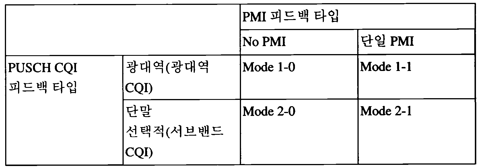
PDCCH 신호로 전송되는 PUSCH 스케줄링 제어신호(UL Grant)에 CQI를 전송하도록 요청하는 제어 신호가 포함될 수 있다. 다음 표 3은 PUSCH를 통해 CQI, 프리코딩 행렬 인덱스(PMI: Precoding Matrix Index), 랭크 지시자(RI: Rank Indicator)를 전송할 때의 단말의 모드를 나타낸다.A control signal for requesting to transmit a CQI may be included in a PUSCH scheduling control signal (UL Grant) transmitted as a PDCCH signal. Table 3 below shows a mode of a terminal when transmitting a CQI, a precoding matrix index (PMI), and a rank indicator (RI) through a PUSCH.

표 3의 전송 모드는 상위 레이어에서 선택되며, CQI/PMI/RI는 모두 같은 PUSCH 서브프레임에서 전송된다. 이하에서는, 각 모드에 따른 단말의 상향링크 전송 방법에 대해서 설명한다.The transmission mode of Table 3 is selected in the upper layer, and CQI / PMI / RI are all transmitted in the same PUSCH subframe. Hereinafter, an uplink transmission method of a terminal according to each mode will be described.
모드 1-2(Mode 1-2)는 각각의 서브밴드에 대해서 데이터가 서브밴드만을 통해서 전송된다는 가정하에 프리코딩 행렬을 선택하는 경우를 나타낸다. 단말은 시스템 대역 또는 상위 레이어에서 지정한 대역(set S) 전체에 대해서 선택한 프리코딩 행렬을 가정하여 CQI를 생성한다. 모드 1-2에서 단말은 CQI와 각 서브밴드의 PMI 값을 전송할 수 있다. 이때, 각 서브밴드의 크기는 시스템 대역의 크기에 따라 달라질 수 있다.Mode 1-2 represents a case in which a precoding matrix is selected on the assumption that data is transmitted only through subbands for each subband. The UE generates a CQI assuming a precoding matrix selected for the entire band (set S) designated by the system band or the upper layer. In mode 1-2, the UE may transmit the CQI and the PMI value of each subband. In this case, the size of each subband may vary depending on the size of the system band.
모드 2-0(Mode 2-0)인 단말은 시스템 대역 또는 상위 레이어에서 지정한 지정 대역(set S)에 대해서 선호하는 M개의 서브밴드를 선택할 수 있다. 단말은 선택한 M개의 서브밴드에 대해서 데이터를 전송한다는 가정하에 하나의 CQI 값을 생성할 수 있다. 단말은 추가로 시스템 대역 또는 set S에 대해서 하나의 CQI (wideband CQI) 값을 보고하는 것이 바람직하다. 단말은 선택한 M개의 서브밴드들에 대해서 다수 개의 코드워드가 있을 경우, 각 코드워드에 대한 CQI 값을 차분 형식으로 정의한다.The UE in mode 2-0 may select the M subbands that are preferred for the designated band set S designated by the system band or the upper layer. The UE may generate one CQI value on the assumption that data is transmitted for the selected M subbands. It is preferable that the UE reports one wideband CQI (CQI) value for the system band or set S. When there are a plurality of codewords for the selected M subbands, the terminal defines a CQI value for each codeword in a differential format.
이때, 차분 CQI 값은 선택한 M개의 서브밴드에 대한 CQI 값에 해당하는 인덱스와 광대역 CQI(WB-CQI: Wideband CQI) 인덱스의 차이값으로 결정된다.In this case, the differential CQI value is determined as a difference value between an index corresponding to the CQI values for the selected M subbands and a wideband CQI (WB-CQI) index.
모드 2-0인 단말은 선택한 M개의 서브밴드의 위치에 대한 정보, 선택한 M개의 서브밴드들에 대한 하나의 CQI 값 및 전 대역 또는 지정 대역(set S)에 대해서 생성한 CQI 값을 기지국으로 전송할 수 있다. 이때, 서브밴드의 크기 및 M값은 시스템 대역의 크기에 따라 달라질 수 있다.The UE in mode 2-0 transmits information on the location of the selected M subbands, one CQI value for the selected M subbands, and a CQI value generated for all bands or a set band (set S) to the base station. Can be. In this case, the size of the subband and the M value may vary depending on the size of the system band.
모드 2-2(Mode 2-2)인 단말은 M개의 선호하는 서브밴드를 통하여 데이터를 전송한다는 가정하에, M개의 선호 서브밴드의 위치와 M개의 선호 서브밴드에 대한 단일 프리코딩 행렬을 동시에 선택할 수 있다. 이때, M개의 선호 서브밴드에 대한CQI 값은 코드워드마다 정의된다. 또한, 단말은 추가로 시스템 대역 또는 지정 대역(set S)에 대해서 광대역 CQI(wideband CQI) 값을 생성한다.Assuming that the UE in mode 2-2 transmits data through M preferred subbands, it simultaneously selects the positions of M preferred subbands and a single precoding matrix for M preferred subbands. Can be. In this case, CQI values for M preferred subbands are defined for each codeword. In addition, the terminal further generates a wideband CQI (wideband CQI) value for the system band or the designated band (set S).
모드 2-2인 단말은 M개의 선호하는 서브밴드의 위치에 대한 정보, 선택된 M개의 서브밴드들에 대한 하나의 CQI 값, M개의 선호하는 서브밴드에 대한 단일 PMI, 광대역 PMI, 광대역 CQI 값을 기지국으로 전송할 수 있다. 이때, 서브밴드의 크기 및 M 값은 시스템 대역의 크기에 따라 달라질 수 있다.The UE in mode 2-2 may provide information on the location of the M preferred subbands, one CQI value for the selected M subbands, a single PMI for the M preferred subbands, a wideband PMI, and a wideband CQI value. It can transmit to the base station. In this case, the size of the subband and the M value may vary depending on the size of the system band.
모드 3-0(Mode 3-0)인 단말은 광대역 CQI 값을 생성한다. 단말은 각 서브밴드를 통해서 데이터를 전송한다는 가정하에 각 서브밴드에 대한 CQI 값을 생성한다. 이때, RI > 1이더라도 CQI 값은 첫 번째 코드워드에 대한 CQI 값만을 나타낸다.The UE in mode 3-0 generates a wideband CQI value. The UE generates a CQI value for each subband assuming that data is transmitted through each subband. At this time, even if RI> 1, the CQI value represents only the CQI value for the first codeword.
모드 3-1(Mode 3-1)인 단말은 시스템 대역 또는 지정대역(set S)에 대해서 단일 프리코딩 행렬(precoding matrix)을 생성한다. 단말은 각 서브밴드에 대해서 앞서 생성한 단일 프리코딩 행렬을 가정하고, 코드워드 별로 서브밴드 CQI를 생성한다. 또한, 단말은 단일 프리코딩 행렬을 가정하고 광대역 CQI를 생성할 수 있다. 각 서브밴드의 CQI 값은 차분 형식으로 표현될 수 있다. 서브밴드 CQI 값은 서브밴드 CQI 인덱스와 광대역 CQI 인덱스의 차이값으로 계산된다. 이때, 서브밴드의 크기는 시스템 대역의 크기에 따라 달라질 수 있다.A terminal in mode 3-1 generates a single precoding matrix for a system band or a set band (set S). The UE assumes a single precoding matrix previously generated for each subband and generates subband CQI for each codeword. Further, the UE can generate a wideband CQI assuming a single precoding matrix. The CQI value of each subband may be expressed in a difference form. The subband CQI value is calculated as a difference between the subband CQI index and the wideband CQI index. In this case, the size of the subband may vary depending on the size of the system band.
2) 2) PUCCHPUCCH 를 통한 주기적인 Periodic through CQICQI /Of PMIPMI /Of RIRI 전송 send
단말은 제어신호(e.g. CQI/PMI/RI 정보)를 PUCCH를 통하여 기지국에 주기적으로 전송할 수 있다. 만약, 단말이 사용자 데이터를 전송하라는 제어신호를 수신하였을 경우에는, 단말은 PUSCH를 통하여 CQI를 전송할 수 있다. 제어신호가 PUSCH를 통하여 전송되더라도 CQI/PMI/RI는 다음 표 4에서 정의된 모드들 중 하나의 방식에 의해 전송될 수 있다.The terminal may periodically transmit a control signal (e.g. CQI / PMI / RI information) to the base station via the PUCCH. If the terminal receives a control signal for transmitting user data, the terminal may transmit the CQI through the PUSCH. Even if the control signal is transmitted through the PUSCH, the CQI / PMI / RI may be transmitted by one of the modes defined in Table 4 below.
단말은 표 4와 같은 전송 모드를 가질 수 있다. 표 4를 참조하면, 모드 2-0(Mode 2-0) 및 모드 2-1(Mode 2-1)의 경우, 대역폭 파트(BP: Bandwidth Part)는 주파수 영역에서 연속적으로 위치한 서브밴드들의 집합이며 시스템 대역 또는 지정대역(set S)를 모두 커버할 수 있다. 표 3에서 각 서브밴드의 크기, BP의 크기 및 BP의 개수는 시스템 대역의 크기에 따라 달라질 수 있다. 또한, 단말은 시스템 대역 또는 지정대역(set S)을 커버할 수 있도록 BP 별로 CQI를 주파수 영역에서 오름차순으로 전송한다.The terminal may have a transmission mode as shown in Table 4. Referring to Table 4, in case of Mode 2-0 and Mode 2-1, the bandwidth part (BP) is a set of subbands consecutively located in the frequency domain. It can cover both the system band or the set band (set S). In Table 3, the size of each subband, the size of the BP, and the number of BPs may vary depending on the size of the system band. In addition, the terminal transmits the CQI in ascending order in the frequency domain for each BP to cover the system band or the set band (set S).
CQI/PMI/RI의 전송 조합에 따라, 단말은 다음과 같은 4개의 전송 타입을 가질 수 있다.According to the transmission combination of CQI / PMI / RI, the UE may have four transmission types as follows.
i) 제 1 타입(Type 1): 모드 2-0(Mode 2-0), 모드 2-1(Mode 2-1)의 서브밴드 CQI(SB-CQI)를 전송한다.i) First Type (Type 1): Subband CQI (SB-CQI) of Mode 2-0 (Mode 2-0) and Mode 2-1 is transmitted.
ii) 제 2 타입(Type 2): 광대역 CQI 및 PMI(WB-CQI/PMI)를 전송한다.ii) Second Type (Type 2): transmits wideband CQI and PMI (WB-CQI / PMI).
iii) 제 3 타입(Type 3): RI를 전송한다.iii) Type 3: Type RI is transmitted.
iv) 제 4 타입(Type 4): 광대역 CQI를 전송한다.iv) Fourth Type (Type 4): transmit a wideband CQI.
단말이 RI와 광대역 CQI/PMI를 전송하는 경우, CQI/PMI는 서로 다른 주기와 오프셋을 가지는 서브프레임에 전송된다. 또한, RI와 광대역 CQI/PMI가 같은 서브프레임에 전송되어야 하는 경우에는 CQI/PMI는 전송되지 않는다.When the UE transmits the RI and the wideband CQI / PMI, the CQI / PMI is transmitted in subframes having different periods and offsets. In addition, when RI and wideband CQI / PMI are to be transmitted in the same subframe, CQI / PMI is not transmitted.
표 4에서 광대역 CQI/PMI 및 서브밴드 CQI의 전송 주기는 P이고, 다음의 특징을 갖는다.In Table 4, the transmission period of the wideband CQI / PMI and the subband CQI is P, and has the following characteristics.
- 광대역 CQI/PMI는 H*P의 주기를 갖는다. 이 때, H=J*K+1이고, J는 BP의 개수, K는 BP의 전체 주기의 횟수이다. 즉, 단말은 {0, H, 2H, …}에 전송한다.Wideband CQI / PMI has a period of H * P. At this time, H = J * K + 1, J is the number of BPs, and K is the number of total cycles of the BPs. That is, the terminal is {0, H, 2H,... }.
- 광대역 CQI/PMI를 전송하는 시점이외의 J*K 시점에서는 CQI를 전송한다.The CQI is transmitted at the J * K point other than the wideband CQI / PMI point.
표 4에서 RI의 전송 주기는 광대역 CQI/PMI 주기의 M 배이며, 다음의 특징을 갖는다.In Table 4, the transmission period of RI is M times the wideband CQI / PMI period, and has the following characteristics.
- RI와 광대역 CQI/PMI의 오프셋은 O이고, RI와 광대역 CQI/PMI가 동일한 서브프레임에 전송되는 경우 광대역 CQI/PMI는 전송되지 않는다.The offset of the RI and the wideband CQI / PMI is O, and when the RI and the wideband CQI / PMI are transmitted in the same subframe, the wideband CQI / PMI is not transmitted.
표 4에서 개시된 파라미터 P, H, K 및 O는 모두 단말의 상위 레이어에서 결정하여 단말의 물리계층으로 시그널링된다.The parameters P, H, K and O disclosed in Table 4 are all determined by the upper layer of the terminal and signaled to the physical layer of the terminal.
이하에서는 표 4를 참고하여, 단말의 모드에 다른 피드백 동작에 대해서 설명한다. 단말이 모드 1-0(Mode 1-0)이고 RI를 기지국에 전송하는 경우, 단말은 시스템 대역 또는 지정 대역(set S)에 대하여 RI를 생성하고, RI를 전송하기 위한 제 3 타입 리포트를 기지국에 전송한다. 단말이 CQI를 전송하는 경우, 광대역 CQI를 전송한다.Hereinafter, with reference to Table 4, a different feedback operation to the mode of the terminal will be described. When the terminal is in mode 1-0 (mode 1-0) and transmits the RI to the base station, the terminal generates the RI for the system band or the designated band (set S), and the base station generates a third type report for transmitting the RI To transmit. When the terminal transmits the CQI, it transmits a wideband CQI.
단말이 모드 1-1(Mode 1-1)이고 RI를 전송하는 경우, 시스템 대역 또는 지정 대역(set S)에 대하여 RI를 생성하고, RI를 전송하기 위한 제 3 타입 리포트를 기지국에 전송한다. 단말이 CQI/PMI를 전송하는 경우, 가장 최근에 전송한 RI를 고려하여 단일 프리코딩 행렬을 선정한다. 즉, 단말은 광대역 CQI, 단일 프리코딩 행렬, 차분 광대역 CQI로 구성된 제 2 타입 리포트를 기지국으로 전송한다.When the terminal is in mode 1-1 (Mode 1-1) and transmits an RI, the UE generates an RI for a system band or a designated band (set S) and transmits a third type report for transmitting the RI to the base station. When the UE transmits CQI / PMI, a single precoding matrix is selected in consideration of the most recently transmitted RI. That is, the terminal transmits a second type report consisting of a wideband CQI, a single precoding matrix, and a differential wideband CQI to the base station.
단말이 모드 2-0(Mode 2-0)이고 RI를 전송하는 경우, 시스템 대역 또는 지정 대역(set S)에 대하여 RI를 생성하고, RI를 전송하기 위한 제 3 타입 리포트를 기지국에 전송한다. 단말이 광대역 CQI를 전송하는 경우, 가장 최근에 전송한 RI를 가정하여 광대역 CQI를 생성하고 제 4 타입 리포트를 기지국으로 전송한다. 단말은 선택한 서브밴드에 대한 CQI를 전송하는 경우, 단말은 N개의 서브밴드로 구성된 J개의 BP에 대해서 가장 선호하는 서브밴드를 선택하여, 제 1 타입 리포트를 기지국으로 전송한다. 제 1 타입 리포트는 BP에 따라서 1개 이상의 서브프레임을 통해 전송될 수 있다.When the terminal is in mode 2-0 (Mode 2-0) and transmits an RI, the UE generates an RI for a system band or a designated band (set S) and transmits a third type report for transmitting the RI to the base station. When the terminal transmits the wideband CQI, the wideband CQI is generated assuming the most recently transmitted RI, and the fourth type report is transmitted to the base station. When the terminal transmits the CQI for the selected subband, the terminal selects the most preferred subband for J BPs composed of N subbands and transmits a first type report to the base station. The first type report may be transmitted on one or more subframes according to the BP.
단말이 모드 2-1(Mode 2-1)이고 RI를 전송하는 경우, 시스템 대역 또는 지정대역(set S)에 대하여 RI를 생성하고, RI를 전송하기 위한 제 3 타입 리포트를 기지국에 전송한다. 단말이 광대역 CQI를 기지국에 전송하는 경우, 가장 최근에 전송한 RI를 고려하여 광대역 CQI를 생성하고 제 4 타입 리포트를 기지국에 전송한다. 선택된 서브밴드들에 대한 CQI가 전송되는 경우, 단말은 Nj개로 구성된 J개의 BP에 대해서, 가장 최근에 전송한 PMI/RI를 고려하여 BP 내에 선택된 서브밴드들에 대한 단일 CQI 값과, RI가 1보다 큰 경우에는 가장 최근에 전송한 RI와 선택된 서브밴드에 단일 프리코딩 행렬을 사용한 것을 가정하여 코드워드의 CQI 차이를 생성하여 제 1 타입 리포트를 기지국에 전송한다.When the terminal is in mode 2-1 (Mode 2-1) and transmits an RI, the UE generates an RI for a system band or a designated band (set S) and transmits a third type report for transmitting the RI to the base station. When the terminal transmits the wideband CQI to the base station, the wideband CQI is generated in consideration of the most recently transmitted RI and a fourth type report is transmitted to the base station. When the CQIs for the selected subbands are transmitted, the UE has a single CQI value for the subbands selected in the BP in consideration of the most recently transmitted PMI / RI for the N j BPs, and RI is 1 If larger, assuming that a single precoding matrix is used for the most recently transmitted RI and the selected subband, a CQI difference of codewords is generated and a first type report is transmitted to the base station.
3. 3. 멀티캐리어Multicarrier 환경 Environment
본 발명의 실시예들에서 고려하는 통신 환경은 멀티캐리어(Multi-carrier) 지원 환경을 포함한다. 즉, 본 발명에서 사용되는 멀티캐리어 시스템 또는 반송파 집성 시스템(carrier aggregation system)이라 함은 광대역을 지원하기 위해서 목표로 하는 광대역을 구성할 때, 목표 대역보다 작은 대역폭(bandwidth)을 가지는 1개 이상의 캐리어(carrier)를 결합(aggregation)하여 사용하는 시스템을 말한다.The communication environment considered in the embodiments of the present invention includes a multi-carrier support environment. That is, the multicarrier system or carrier aggregation system used in the present invention refers to one or more carriers having a bandwidth smaller than the target band when configuring a target broadband to support the broadband. Refers to a system using aggregation of carriers.
본 발명에서 멀티 캐리어는 반송파의 집성(또는, 캐리어 결합)을 의미하며, 이때 반송파 집성은 인접한 캐리어 간의 결합뿐 아니라 비 인접한 캐리어 간의 결합을 모두 의미한다. 또한, 캐리어 결합은 반송파 집성, 대역폭 결합 등과 같은 용어와 혼용되어 사용될 수 있다.In the present invention, the multi-carrier refers to the aggregation (or carrier coupling) of the carrier, wherein carrier aggregation means not only coupling between adjacent carriers, but also coupling between non-adjacent carriers. In addition, carrier combining may be used interchangeably with terms such as carrier aggregation, bandwidth combining, and the like.
두 개 이상의 컴포넌트 캐리어(CC: Component Carrier)가 결합되어 구성되는 멀티캐리어(즉, 반송파 집성)는 LTE-A 시스템에서는 100MHz 대역폭까지 지원하는 것을 목표로 한다. 목표 대역보다 작은 대역폭을 가지는 1개 이상의 캐리어를 결합할 때, 결합하는 캐리어의 대역폭은 기존 IMT 시스템과의 호환성(backward compatibility) 유지를 위해서 기존 시스템에서 사용하는 대역폭으로 제한할 수 있다.A multicarrier (ie, carrier aggregation) in which two or more component carriers (CC) are combined is aimed at supporting up to 100 MHz bandwidth in an LTE-A system. When combining one or more carriers having a bandwidth smaller than the target band, the bandwidth of the combining carrier may be limited to the bandwidth used by the existing system to maintain backward compatibility with the existing IMT system.
예를 들어서 3GPP LTE 시스템(LTE R-8 시스템)에서는 {1.4, 3, 5, 10, 15, 20}MHz 대역폭을 지원하며, 3GPP LTE_advanced 시스템(즉, LTE_A)에서는 LTE에서 지원하는 상기의 대역폭들을 이용하여 20MHz보다 큰 대역폭을 지원하도록 할 수 있다. 또한, 본 발명에서 사용되는 멀티캐리어 시스템은 기존 시스템에서 사용하는 대역폭과 상관없이 새로운 대역폭을 정의하여 캐리어 결합(즉, 반송파 집성 등)을 지원하도록 할 수도 있다.For example, the 3GPP LTE system (LTE R-8 system) supports {1.4, 3, 5, 10, 15, 20} MHz bandwidth, and the 3GPP LTE_advanced system (ie LTE_A) supports the above bandwidths supported by LTE. It can be used to support bandwidth greater than 20MHz. In addition, the multicarrier system used in the present invention may support carrier aggregation (ie, carrier aggregation, etc.) by defining a new bandwidth regardless of the bandwidth used in the existing system.
도 7은 LTE 시스템의 컴포넌트 캐리어(CC) 및 LTE_A 시스템에서 사용되는 멀티 캐리어 결합(반송파 집성)의 일례를 나타내는 도면이다.7 is a diagram illustrating an example of multi-carrier combining (carrier aggregation) used in a component carrier (CC) of the LTE system and the LTE_A system.
도 7(a)는 LTE 시스템에서 사용되는 단일 캐리어 구조를 나타낸다. 컴포넌트 캐리어에는 하향링크 컴포넌트 캐리어(DL CC)와 상향링크 컴포넌트 캐리어(UL CC)가 있다. 하나의 컴포넌트 캐리어는 20MHz의 주파수 범위를 가질 수 있다.7 (a) shows a single carrier structure used in an LTE system. The component carrier includes a downlink component carrier (DL CC) and an uplink component carrier (UL CC). One component carrier may have a frequency range of 20 MHz.
도 7(b)는 LTE_A 시스템에서 사용되는 멀티 캐리어 구조를 나타낸다. 도 7(b)의 경우에 20MHz의 주파수 크기를 갖는 3 개의 컴포넌트 캐리어가 결합된 경우를 나타낸다. 멀티 캐리어 집성의 경우 단말은 3 개의 컴포넌트 캐리어를 동시에 모니터링할 수 있고, 하향링크 신호/데이터를 수신할 수 있고 상향링크 신호/데이터를 송신할 수 있다.7 (b) shows a multi-carrier structure used in the LTE_A system. In case of FIG. 7B, three component carriers having a frequency size of 20 MHz are combined. In the case of multi-carrier aggregation, the UE may simultaneously monitor three component carriers, receive downlink signals / data, and transmit uplink signals / data.
만약, 특정 기지국(eNB: e-NodeB) 영역에서 N개의 DL CC가 관리되는 경우에는, 네트워크는 단말에 M (M≤N)개의 DL CC를 할당할 수 있다. 이때 단말은 M 개의 제한된 DL CC 만을 모니터링하고, DL 신호를 수신할 수 있다. 또한, 네트워크는 L (L≤M≤N)개의 DL CC에 우선순위를 주어 주된 DL CC로 단말에 할당할 수 있으며, 이러한 경우 UE는 L 개의 DL CC는 반드시 모니터링해야한다. 이러한 방식은 상향링크 전송에도 적용될 수 있다.If N DL CCs are managed in a specific base station (eNB: e-NodeB) region, the network may allocate M (M ≦ N) DL CCs to the terminal. In this case, the UE may monitor only M limited DL CCs and receive a DL signal. In addition, the network may give priority to L (L ≦ M ≦ N) DL CCs and allocate them to the UE as a main DL CC. In this case, the UE must monitor the L DL CCs. This method can also be applied to uplink transmission.
LTE-A 시스템은 무선 자원을 관리하기 위해 셀(cell)의 개념을 사용한다. 셀은 하향링크 자원과 상향링크 자원의 조합으로 정의되며, 상향링크 자원은 선택적으로 정의될 수 있다. 예를 들어, 셀은 하향링크 자원 단독, 또는 하향링크 자원과 상향링크 자원으로 구성될 수 있다. 멀티캐리어(즉, 캐리어 병합)가 지원되는 경우, 하향링크 자원의 캐리어 주파수(또는, DL CC)와 상향링크 자원의 캐리어 주파수(또는, UL CC) 사이의 링키지(linkage)는 시스템 정보에 의해 지시될 수 있다. 즉, 하나의 셀은 하나 이상의 하향링크 컴포넌트 캐리어들로 구성되며, 선택적으로 하나 이상의 상향링크 컴포넌트 캐리어들을 포함할 수 있다.The LTE-A system uses the concept of a cell to manage radio resources. The cell is defined by a combination of downlink resources and uplink resources, and uplink resources may be selectively defined. For example, the cell may be configured with only downlink resources or with downlink resources and uplink resources. If multicarrier (ie carrier aggregation) is supported, the linkage between the carrier frequency (or DL CC) of the downlink resource and the carrier frequency (or UL CC) of the uplink resource is indicated by the system information. Can be. That is, one cell is composed of one or more downlink component carriers, and may optionally include one or more uplink component carriers.
LTE-A 시스템에서 사용되는 셀은 프라이머리 셀(PCell: Primary Cell) 및 세컨더리 셀(SCell: Secondary Cell)을 포함하는 개념이다. P셀은 프라이머리 주파수(또는, primary CC) 상에서 동작하는 셀을 의미하고, S셀은 세컨더리 주파수(또는, Secondary CC) 상에서 동작하는 셀을 의미할 수 있다. 다만, 특정 단말에는 P셀은 하나만 할당되며, S셀은 하나 이상 할당될 수 있다.The cell used in the LTE-A system is a concept including a primary cell (PCell) and a secondary cell (SCell). The P cell may mean a cell operating on a primary frequency (or primary CC), and the S cell may mean a cell operating on a secondary frequency (or secondary CC). However, only one P cell is allocated to a specific terminal, and one or more S cells may be allocated.
P셀은 단말이 초기 연결 설정(initial connection establishment) 과정을 수행하거나 연결 재-설정 과정을 수행하는데 사용된다. P셀은 핸드오버 과정에서 지시된 셀을 지칭할 수도 있다. S셀은 RRC 연결이 설정이 이루어진 이후에 구성이 가능하며 추가적인 무선 자원을 제공하는데 사용될 수 있다.The PCell is used for the UE to perform an initial connection establishment process or to perform a connection re-establishment process. The Pcell may refer to a cell indicated in the handover process. The SCell can be configured after the RRC connection is established and can be used to provide additional radio resources.
P셀과 S셀은 서빙 셀로 사용될 수 있다. RRC_CONNECTED 상태에 있지만 캐리어 병합이 설정되지 않았거나 캐리어 병합을 지원하지 않는 단말의 경우, P셀로만 구성된 서빙 셀이 단 하나 존재한다. 반면, RRC_CONNECTED 상태에 있고 캐리어 병합이 설정된 단말의 경우 하나 이상의 서빙 셀이 존재할 수 있으며, 전체 서빙 셀에는 P셀과 하나 이상의 S셀이 포함된다.P cell and S cell may be used as a serving cell. In case of the UE that is in the RRC_CONNECTED state but the carrier aggregation is not configured or does not support the carrier aggregation, there is only one serving cell composed of the PCell. On the other hand, in case of a UE in RRC_CONNECTED state and carrier aggregation is configured, one or more serving cells may exist, and the entire serving cell includes a PCell and one or more SCells.
초기 보안 활성화 과정이 시작된 이후에, E-UTRAN은 연결 설정 과정에서 초기에 구성되는 P셀에 부가하여 하나 이상의 S셀을 포함하는 네트워크를 구성할 수 있다. 멀티캐리어 환경에서 P셀 및 S셀은 각각의 컴포넌트 캐리어로서 동작할 수 있다. 즉, 반송파 정합은 P셀과 하나 이상의 S셀의 결합으로 이해될 수 있다. 이하의 실시예에서는 프라이머리 컴포넌트 캐리어(PCC)는 P셀과 동일한 의미로 사용될 수 있으며, 세컨더리 컴포넌트 캐리어(SCC)는 S셀과 동일한 의미로 사용될 수 있다.After the initial security activation process begins, the E-UTRAN may configure a network including one or more Scells in addition to the Pcells initially configured in the connection establishment process. In a multicarrier environment, the Pcell and the Scell may operate as respective component carriers. That is, carrier matching may be understood as a combination of a Pcell and one or more Scells. In the following embodiments, the primary component carrier (PCC) may be used in the same sense as the PCell, and the secondary component carrier (SCC) may be used in the same sense as the SCell.
도 8은 본 발명에서 사용될 수 있는 크로스 컴포넌트 캐리어 스케줄링 방법의 일례를 나타내는 도면이다.8 is a diagram illustrating an example of a cross-component carrier scheduling method that can be used in the present invention.
LTE Rel-8 규격에서 정의하는 PDCCH 구조 및 DCI 포맷에서는 크로스 캐리어 스케줄링을 지원하지 않는다. 즉, LTE Rel-8의 DCI 포맷과 PDCCH 전송 구조(동일 코딩 방법 및 동일 CCE 기반의 자원 맵핑)를 그대로 사용한다. 예를 들어, 컴포넌트 캐리어 상의 PDCCH는 PDSCH 자원들을 동일한 컴포넌트 캐리어에 할당하고, PUSCH 자원들을 연계된 UL 컴포넌트 캐리어 상에 할당한다. 이러한 경우에는 캐리어 지시자 필드(CIF: Carrier Indicator Field)가 필요하지 않다. 또한, 관련된 PDSCH 전송과 UL A/N, PUSCH 전송 및 PHICH 전송 방법도 LTE Rel-8 규격의 내용을 그대로 따르게 된다.The PDCCH structure and DCI format defined in the LTE Rel-8 standard do not support cross carrier scheduling. That is, the DCI format of the LTE Rel-8 and the PDCCH transmission structure (same coding method and resource mapping based on the same CCE) are used as they are. For example, a PDCCH on a component carrier allocates PDSCH resources to the same component carrier and allocates PUSCH resources on the associated UL component carrier. In this case, a Carrier Indicator Field (CIF) is not needed. In addition, related PDSCH transmission, UL A / N, PUSCH transmission and PHICH transmission method also follows the contents of the LTE Rel-8 standard.
LTE-A 규격에서 정의하는 PDCCH 구조 및 DCI 포맷에서는 크로스 캐리어 스케줄링을 지원할 수 있다. 즉, PDCCH(DL Grant)와 PDSCH가 각각 다른 DL CC로 전송될 수 있거나, DL CC에서 전송된 PDCCH(UL Grant)에 따라서 전송되는 PUSCH가 UL 그랜트를 수신한 DL CC와 연계되어 있는 UL CC가 아닌 다른 UL CC를 통해 전송되는 경우를 포함할 수 있다.The PDCCH structure and the DCI format defined in the LTE-A standard may support cross carrier scheduling. That is, a PDCCH (DL Grant) and a PDSCH may be transmitted to different DL CCs, or a UL CC in which a PUSCH transmitted according to a PDCCH (UL Grant) transmitted in a DL CC is associated with a DL CC having received an UL grant. It may include the case that is transmitted through other UL CC.
이러한 경우에는 PDCCH에 해당 PDCCH가 지시하는 PDSCH/PUSCH가 어느 DL/UL CC를 통해서 전송되는지를 알려주는 캐리어 지시자 필드(CIF)가 필요하다. 예를 들어, PDCCH는 PDSCH 자원 또는 PUSCH 자원을 캐리어 지시자 필드를 이용하여 다수의 컴포넌트 캐리어들 중 하나에 할당할 수 있다. 이를 위해 LTE-A 시스템의 DCI 포맷은 1 내지 3 비트의 CFI에 따라 확장될 수 있으며, LTE Rel-8의 PDCCH 구조를 재사용할 수 있다.In this case, a carrier indicator field (CIF) indicating which DL / UL CC the PDSCH / PUSCH indicated by the corresponding PDCCH is transmitted to the PDCCH is required. For example, the PDCCH may allocate PDSCH resource or PUSCH resource to one of a plurality of component carriers using a carrier indicator field. To this end, the DCI format of the LTE-A system can be extended according to 1 to 3 bits of CFI, and can reuse the PDCCH structure of the LTE Rel-8.
크로스 캐리어 스케줄링의 허용 여부는 단말 특정(UE-specific), 단말 그룹 특정(UE group-specific) 또는 셀 특정(Cell-specific)하게 결정될 수 있으며, 크로스 케리어 스케줄링의 동작을 반정적(semi-static)으로 변경(toggling)함으로써 시그널링 오버헤드(signaling overhead)를 줄일 수 있다.Whether to allow cross-carrier scheduling may be determined UE-specifically, UE group-specifically, or cell-specifically, and semi-static operation of cross carrier scheduling may be performed. Signaling overhead can be reduced by toggling.
이에 따라 크로스 캐리어 스케줄링의 허용, 즉 활성화/비활성화(activation/de-activation)에 따른 CIF의 크기는 반정적으로 설정될 수 있다. 이는, LTE Rel-8에서 단말 특정 전송 모드가 반 정적으로 결정되는 것과 유사하다. 그러나, 통신 환경에 따라 CIF의 크기는 3비트로서 고정될 수 있으며, 이때 CIF의 위치는 DCI 포맷의 크기에 불문하고 고정될 수 있다.Accordingly, the size of the CIF according to the permission of the cross carrier scheduling, that is, activation / de-activation may be set semi-statically. This is similar to the terminal specific transmission mode is determined semi-statically in LTE Rel-8. However, depending on the communication environment, the size of the CIF may be fixed as 3 bits, and the position of the CIF may be fixed regardless of the size of the DCI format.
크로스 캐리어 스케줄링이 비활성화된 경우에는 PDCCH 모티터링 집합이 항상 UE DL CC 집합과 동일하다는 것을 의미하며, 이러한 경우에는 PDCCH 모니터링 셋에 대한 별도의 시그널링과 같은 지시가 필요하지 않다. 크로스 캐리어 스케줄링이 활성화된 경우에는 PDCCH 모니터링 집합이 UE DL CC 집합 내에서 정의되는 것이 바람직하며, 이러한 경우에는 PDCCH 모니터링 셋에 대한 별도의 시그널링과 같은 지시가 필요하다.When cross-carrier scheduling is deactivated, it means that the PDCCH monitoring set is always the same as the UE DL CC set. In this case, no indication such as separate signaling for the PDCCH monitoring set is necessary. When cross-carrier scheduling is activated, the PDCCH monitoring set is preferably defined in the UE DL CC set. In this case, an indication such as separate signaling for the PDCCH monitoring set is required.
CIF가 존재하는 경우에, 기지국은 단말의 블라인드 디코딩 횟수를 줄이기 위해 PDCCH를 모니터링하기 위한 DL CC 집합을 할당할 수 있다. 이러한 DL CC 집합은 전체 결합된 DL CC들의 일부일 수 있으며, 단말은 할당 받은 DL CC 집합 내에서만 PDCCH를 검출 및 디코딩할 수 있다. 즉, 단말에 PDSCH 및 PUSCH를 스케줄하기 위해 기지국은 DL CC 모니터링 집합을 통해서만 PDCCH들을 전송할 수 있다. PDCCH DL CC 모니터링 집합은 단말 특정, 단말 그룹 특정 또는 셀 특정으로 설정될 수 있다.If there is a CIF, the base station may allocate a DL CC set for monitoring the PDCCH to reduce the number of blind decoding of the terminal. The DL CC set may be part of the combined DL CCs, and the UE may detect and decode the PDCCH only within the allocated DL CC set. That is, in order to schedule PDSCH and PUSCH to the UE, the base station may transmit PDCCHs only through the DL CC monitoring set. The PDCCH DL CC monitoring set may be set to UE specific, UE group specific or cell specific.
예를 들어, 도 8을 참조하면, LTE-A 단말에 대해 3개의 DL CC가 결합된 DL 서브프레임을 나타낸다. 이때, DL CC A는 PDCCH 모니터링 DL CC로서 구성될 수 있다. 만약, CIF가 활성화되지 않으면, PDCCH 및 PDSCH는 LTE Rel-8 규칙에 따라 스케줄링된 동일 DL CC를 통해 전송된다. 만약, CIF가 활성화되면, PDCCH는 모니터링 DL CC A를 통해 전송되고, PDSCH는 DL CC A 뿐 아니라 DL CC B 및 DL CC C를 통해서도 전송될 수 있다. 다만, PDCCH는 DL CC 모니터링 셋이 아닌 DL CC B 및 C를 통해서는 전송될 수 없다.For example, referring to FIG. 8, a DL subframe in which three DL CCs are combined for an LTE-A terminal is illustrated. In this case, DL CC A may be configured as a PDCCH monitoring DL CC. If CIF is not activated, the PDCCH and PDSCH are transmitted on the same DL CC scheduled according to the LTE Rel-8 rule. If CIF is activated, the PDCCH may be transmitted through the monitoring DL CC A, and the PDSCH may be transmitted through the DL CC B and the DL CC C as well as the DL CC A. However, the PDCCH may not be transmitted through the DL CCs B and C rather than the DL CC monitoring set.
4. 복수의 4. Multiple 서빙serving 셀에 대한 For cell CSICSI 전송 방법 Transmission way
이하에서는 본 발명의 실시예로서 복수의 서빙 셀에 대한 채널상태정보(CSI: Channel State Information) 전송 방법에 대해서 상세히 설명한다.Hereinafter, a method of transmitting channel state information (CSI) for a plurality of serving cells will be described in detail as an embodiment of the present invention.
단말은 둘 이상의 서빙 셀이 할당된 경우 PUCCH 상에서 채널상태정보(CSI)를 기지국에 주기적으로 피드백하도록 상위 계층에 의해 반 정적으로 구성될 수 있다. 이때, CSI는 CQI, PMI, RI 및/또는 프리코딩 타입 지시자(PTI: Precoding Type Indicator)를 포함할 수 있다.The UE may be semi-statically configured by the upper layer to periodically feed back channel state information (CSI) to the base station on the PUCCH when two or more serving cells are allocated. In this case, the CSI may include a CQI, a PMI, an RI, and / or a precoding type indicator (PTI).
LTE Rel-8 시스템에서는 단말로부터 전송되는 CSI 타입을 다음 표 5와 같이 RI, WB-CQI(광대역 CQI)/PMI, SB-CQI(서브밴드 CQI)로 분류하고 있다. 또한, 표 5는 LTE-A 시스템에서 단말이 전송하는 CSI 타입을 각 각 케이스(Case) 별로 나타내고 있다. 각 타입에 따른 CQI 전송 주기를 큰 순서부터 나열하면 RI > WB-CQI/PMI > SB-CQI이다.In the LTE Rel-8 system, the CSI type transmitted from the UE is classified into RI, WB-CQI (wideband CQI) / PMI, and SB-CQI (subband CQI) as shown in Table 5 below. In addition, Table 5 shows the CSI type transmitted by the terminal in each case in the LTE-A system. When the CQI transmission periods according to each type are listed in large order, RI> WB-CQI / PMI> SB-CQI.

표 5를 참조하면, 본 발명에서는 LTE Rel-8 보다 정교한 채널 적응(channel adaptation) 및 셀 간 간섭을 고려한 셀간 협력 전송(CoMP: Cooperative Multi-Point) 등을 통한 성능 개선을 위해 L-PMI(Long-term PMI)와 S-PMI(Short-term PMI)를 사용할 수 있다. 이때, L-PMI의 전송 주기는 S-PMI의 전송 주기보다 긴 것을 가정한다. 이때, L-PMI는 제 1 PMI(1st PMI)로, S-PMI는 제 2 PMI(2nd PMI)로 불릴 수 있다.Referring to Table 5, in the present invention, L-PMI (Long) for performance improvement through Cooperative Multi-Point (CoMP) in consideration of more sophisticated channel adaptation and inter-cell interference than LTE Rel-8 -term PMI) and Short-term PMI (S-PMI) are available. At this time, it is assumed that the transmission period of the L-PMI is longer than the transmission period of the S-PMI. In this case, the L-PMI may be referred to as a first PMI, and the S-PMI may be referred to as a second PMI.
L-PMI 및 S-PMI를 감안한 LTE-A를 위한 CSI 타입은 표 5에 제시된 가능한 케이스(case)들 중에서 특정 케이스를 기반으로 적용될 수 있다. 표 5에서 제 N 타입 CSI는 제 N+1 타입 CSI에 비해 큰 CSI 전송 주기를 갖는다. 또한, 본 발명에서는 제 N 타입 CSI가 제 N+1 타입 CSI에 비해 높은 우선 순위를 가지는 것을 가정한다. 즉, CSI 전송 주기가 긴 순서대로 우선 순위를 가질 수 있다. 또한, 특정 케이스를 기반으로 각 DL CC의 CSI 전송을 위한 CSI 타입 및 개수는 DL CC별로 독립적으로 설정됨을 가정하였다. 이하에서는, 설명의 편의를 위해 표 5의 Case #1의 경우가 적용되는 것을 가정하여 설명한다.The CSI type for LTE-A considering L-PMI and S-PMI may be applied based on a specific case among the possible cases shown in Table 5. In Table 5, the N-type CSI has a larger CSI transmission period compared to the N + 1-type CSI. In addition, the present invention assumes that the N-type CSI has a higher priority than the N + 1-type CSI. That is, the CSI transmission period may have priority in the longest order. In addition, it is assumed that the CSI type and number for CSI transmission of each DL CC are independently set for each DL CC based on a specific case. Hereinafter, it will be described on the assumption that the case of
LTE-A 시스템에서는 복수의 CC가 결합되어 사용될 수 있으므로, 이를 위해 단말로부터 기지국으로 복수의 DL CC에 대한 CSI 전송이 요구된다. 즉 단말은 하나 이상의 서빙 셀에 대한 CSI를 기지국에 전송해야한다. 단말이 제어 채널(e.g. PUCCH)을 통한 주기적인 CSI 전송을 고려할 경우, 복수 DL CC의 CSI 전송을 위한 구성(configuration) 정보(e.g. CSI 전송 주기, CSI 전송 모드 및/또는 CSI 타입 등)는 모든 서빙 셀(e.g. DL CC)에 대하여 또는 서빙셀 그룹별로 동일하거나 혹은 서빙 셀 별로 독립적으로 설정될 수 있다. 또한, 복수의 서빙 셀에 대한 CSI 전송을 위한 PUCCH 인덱스 역시 모든 서빙 셀에 대하여 또는 서빙셀 그룹별로 동일하거나 혹은 서빙셀 별로 다르게 할당될 수 있다.In the LTE-A system, since a plurality of CCs may be combined and used, CSI transmission for a plurality of DL CCs is required from the terminal to the base station. That is, the terminal should transmit the CSI for one or more serving cells to the base station. When the UE considers periodic CSI transmission through a control channel (eg PUCCH), configuration information (eg CSI transmission period, CSI transmission mode and / or CSI type, etc.) for CSI transmission of a plurality of DL CCs are all served. The same may be set for a cell (eg DL CC) or for each serving cell group or independently for each serving cell. In addition, the PUCCH index for CSI transmission for a plurality of serving cells may also be allocated to all serving cells or the same for each serving cell group or differently for each serving cell.
또한, Rel-8 및 LTE-A 시스템을 비롯한 단말의 상향링크 전송시, 전력 증폭기(power amplifier)의 왜곡을 줄이기 위해, 상향링크 전송 신호에 대하여 단일 캐리어(single-carrier) 특성을 유지시키는 것이 요구된다. 이를 위해 복수의 PUCCH가 동일한 서브프레임을 통해 전송되어야 할 경우, 상향링크 전송 신호의 단일 캐리어 특성을 유지시키기 위한 단말의 동작(UE behavior)을 정의하는 것이 필요하다.In addition, in order to reduce distortion of a power amplifier during uplink transmission of a terminal including a Rel-8 and LTE-A system, it is required to maintain a single carrier characteristic for the uplink transmission signal. do. For this purpose, when a plurality of PUCCHs are to be transmitted through the same subframe, it is necessary to define a UE behavior for maintaining a single carrier characteristic of an uplink transmission signal.
이하에서는 멀티캐리어 결합 환경에서 복수의 서빙 셀(DL CC)에 대한 CSI 전송을 위한 단말의 상향링크 동작에 대해서 설명한다. 예를 들어, 단말이 특정 서브프레임에서 복수의 PUCCH 또는 PUSCH를 통해 복수의 DL CC에 대한 CSI 전송이 동시에 요구될 경우, 하나의 PUCCH를 통해 하나의 제어정보(즉, CSI)를 전송하는 방법에 대해서 개시한다. 또한, 복수의 CSI들 중에서 특정 CSI만을 전송할 수 있도록 CSI 우선순위에 따른 CSI 드롭(Dropping) 방법을 개시한다. 예를 들어, 본 발명의 실시예들에서 서빙 셀 타입, CSI 전송 주기 및/또는 CSI 타입에 따라 각 서빙 셀에 대한 CQI를 드롭하는 방법에 대해서 설명한다.Hereinafter, an uplink operation of a terminal for CSI transmission for a plurality of serving cells (DL CCs) in a multicarrier combining environment will be described. For example, when a UE is required to simultaneously transmit CSI for a plurality of DL CCs through a plurality of PUCCHs or PUSCHs in a specific subframe, a method of transmitting one control information (ie, CSI) through one PUCCH It is started. Also, a CSI dropping method according to CSI priority is disclosed so that only a specific CSI can be transmitted among a plurality of CSIs. For example, in the embodiments of the present invention, a method of dropping a CQI for each serving cell according to a serving cell type, a CSI transmission period, and / or a CSI type will be described.
또한, 본 발명의 실시예들에서 컴포넌트 캐리어(CC: Component Carrier)는 셀(Cell) 개념과 혼용될 수 있음을 앞서 설명하였다. 즉, 소정의 서빙 셀은 하나 이상의 하향링크 컴포넌트 캐리어(DL CC)를 기본적으로 포함하고 있으며, 경우에 따라 상향링크 컴포넌트 캐리어(UL CC)를 포함할 수 있다. 또한, 하나의 서빙 셀은 하나의 DL CC 및/또는 UL CC로 사용될 수 있다.In addition, it has been described above that the component carrier (CC) in the embodiments of the present invention may be mixed with the cell concept. That is, a predetermined serving cell basically includes one or more downlink component carriers (DL CCs), and in some cases, may include an uplink component carriers (UL CCs). In addition, one serving cell may be used as one DL CC and / or UL CC.
도 9는 본 발명의 실시예로서 채널상태정보(CSI)의 우선순위에 따른 CSI 보고 방법 중 하나를 나타내는 도면이다.9 is a view showing one of the CSI reporting method according to the priority of the channel state information (CSI) according to an embodiment of the present invention.
이하에서는 본 발명의 실시예로서 각 서빙 셀(e.g. DL CC) 별로 CSI 정보 전송 및 피드백 모드를 독립적으로 설정함으로써, 서빙 셀별로 CSI의 내용을 서로 다르게 구성하는 방법에 대해서 설명한다. 즉, CSI의 내용이 하나 또는 복수의 CSI 보고 타입(CSI reporting type)으로 구성될 수 있다. 이때, CSI 보고 타입은 PUCCH 포맷과 관련되어 생성될 수 있다.Hereinafter, as an embodiment of the present invention, a method of configuring CSI information differently for each serving cell by setting CSI information transmission and feedback modes independently for each serving cell (e.g. DL CC) will be described. That is, the content of the CSI may be configured with one or a plurality of CSI reporting types. In this case, the CSI report type may be generated in association with the PUCCH format.
기지국은 CSI를 보고하기 위해 사용될 수 있는 시간 및 주파수 자원을 제어한다. 본 발명의 실시예들에, CSI는 CQI, PMI(제 1 PMI, 제 2 PMI), PTI 및 RI 중 하나 이상으로 구성될 수 있다.The base station controls the time and frequency resources that can be used to report the CSI. In embodiments of the present invention, the CSI may be composed of one or more of CQI, PMI (first PMI, second PMI), PTI, and RI.
단말이 하나 이상의 서빙 셀을 할당 받은 경우, 단말은 활성화된 모든 서빙 셀에 대해서 주기적으로 CSI를 전송할 수 있다. 단말은 상위계층 시그널을 통해 하나 이상의 서빙 셀에 대한 CSI 보고모드에 대한 정보를 획득할 수 있다. 또한, 단말은 상위계층 시그널을 통해 CQI, PMI, PTI 및 RI 중 하나 이상의 전송주기 및 오프셋 값을 획득할 수 있다(S910).When the UE is assigned one or more serving cells, the UE may periodically transmit CSI for all activated serving cells. The UE may obtain information on the CSI report mode for one or more serving cells through a higher layer signal. In addition, the UE may acquire one or more transmission periods and offset values of CQI, PMI, PTI, and RI through higher layer signals (S910).
또한, 단말은 기지국과 하나 이상의 서빙 셀을 통해 통신을 수행할 수 있으며, 단말은 하향링크 채널들의 상태를 검색 및 측정할 수 있다(S920).In addition, the terminal may communicate with the base station through one or more serving cells, and the terminal may search and measure the states of the downlink channels (S920).
단말은 활성화된 하나 이상의 서빙 셀들에 대한 채널상태정보(CSI)를 각각의 내용에 따른 전송주기에서 기지국에 보고할 수 있다. 즉, 단말은 제 1 서빙셀의 CSI 및 제 2 서빙셀의 CSI를 각 CSI 전송 주기에 따라 기지국으로 전송한다(S930, S940).The terminal may report channel state information (CSI) of one or more activated serving cells to the base station in a transmission period according to each content. That is, the terminal transmits the CSI of the first serving cell and the CSI of the second serving cell to the base station according to each CSI transmission period (S930 and S940).
S930, S940 단계에서, 만약 단말이 PUSCH 및 PUCCH 신호 동시 전송모드로 구성된 경우, 단말은 PUCCH 영역을 통해 각 CSI를 기지국에 주기적으로 보고할 수 있다. 또는, 단말이 PUSCH 및 PUSCH 신호 동시 전송 모드로 구성되지 않은 경우, 단말은 CSI를 PUSCH 신호에 피기백하여 PUSCH 영역을 통해 CSI를 주기적으로 보고할 수 있다.In step S930 and S940, if the terminal is configured in the PUSCH and PUCCH signal simultaneous transmission mode, the terminal may periodically report each CSI to the base station through the PUCCH region. Alternatively, when the terminal is not configured in the simultaneous transmission mode of the PUSCH and the PUSCH signal, the terminal piggybacks the CSI to the PUSCH signal and may periodically report the CSI through the PUSCH region.
다만, 단말이 각 서빙 셀에 대한 CSI 정보를 기지국에 보고하는 도중에, 각 CSI 정보의 전송주기가 동일 서브프레임에서 겹치는 경우가 발생할 수 있다. 즉, 단말이 특정 서브프레임에서 전송해야할 CSI가 충돌할 수 있다(S950).However, while the terminal reports the CSI information for each serving cell to the base station, the transmission period of each CSI information may overlap in the same subframe. That is, the CSI to be transmitted in a specific subframe by the UE may collide (S950).
본 발명의 실시예들에서, 동일 서브프레임에서 둘 이상의 서빙 셀에 대한 CSI 보고가 겹치는 경우 오직 하나의 서빙 셀에 대한 CSI 만을 전송할 수 있다. 따라서, 단말은 PUCCH 포맷과 관련된 CSI 보고 타입의 우선순위를 비교하고(S960), 우선순위가 높은 CSI를 선택하여 기지국에 보고하고 나머지 셀들에 대한 CSI는 드롭할 수 있다(S970).In embodiments of the present invention, when CSI reports for two or more serving cells overlap in the same subframe, only CSI for one serving cell may be transmitted. Accordingly, the UE may compare the priority of the CSI report type related to the PUCCH format (S960), select a CSI having a higher priority, report it to the base station, and drop CSI for the remaining cells (S970).
CSI 보고 타입의 우선순위는 셀 타입, CSI 보고 주기, CSI 보고 타입, 단말의 전송모드, CSI 보고 모드 및/또는 PUCCH 포맷을 고려하여 결정될 수 있다. 이때, CSI 보고 타입은 PUCCH CSI 보고 모드에 따라 전송 주기 및 오프셋들이 결정될 수 있다.The priority of the CSI report type may be determined in consideration of a cell type, a CSI report period, a CSI report type, a transmission mode of a UE, a CSI report mode, and / or a PUCCH format. In this case, the transmission period and offsets may be determined according to the PUCCH CSI report mode as the CSI report type.
이하에서는, CSI 보고 타입의 우선순위에 따라 단말이 CSI를 드롭하는 경우에 대해서 설명한다. CSI 보고 타입은 CSI 보고 모드에 따른 CSI를 나타내고, CSI 보고 모드를 지원하기 위해 사용된다. 표 5에서 CSI 보고 타입의 우선순위는 CSI 타입 1이 가장 높고 CSI 타입 4가 가장 낮음을 가정하고 있다.Hereinafter, a case in which the UE drops the CSI according to the priority of the CSI report type will be described. The CSI report type indicates CSI according to the CSI report mode and is used to support the CSI report mode. In Table 5, it is assumed that the priority of CSI report type is
표 5를 참조하면, 케이스 #3의 경우에, CSI 타입 1은 단말이 RL 및 제 1 PMI(L-PMI)를 기지국에 보고하는 경우(즉, CSI 보고 타입 5)를 나타내고, CSI 타입 2는 단말이 WB-CQI 및 제 2 PMI(S-PMI)를 기지국에 보고하는 경우(즉, CSI 보고 타입 2b)를 나타내며, CSI 타입 3은 단말이 SB-CQI를 기지국에 보고하는 경우(즉, CSI 보고 타입 1)를 나타낸다.Referring to Table 5, in
또한, 케이스 #6의 경우에, CSI 타입 1은 단말이 RI 및 제 1 PMI(L-PMI)를 기지국에 보고하는 경우(즉, CSI 보고 타입 5)를 나타내고, CSI 타입 2는 단말이 WB-CQI를 기지국에 보고하는 경우(즉, CSI 보고 타입 4)를 나타내며, CSI 타입 3은 단말이 SB-CQI 및 제 2 PMI(S-PMI)를 기지국에 보고하는 경우(즉, CSI 보고 타입 1a)를 나타낸다.In addition, in
또한, 케이스 #7의 경우에, CSI 타입 1은 단말이 RI를 기지국에 보고하는 경우(즉, CSI 보고 타입 3)를 나타내고, CSI 타입 2는 단말이 WB-CQI 및 제 1 PMI(L-PMI)를 기지국에 보고하는 경우(즉, CSI 보고 타입 2c)를 나타내며, CSI 타입 3은 단말이 SB-CQI 및 제 2 PMI를 기지국에 보고하는 경우(즉, CSI 보고 타입 1a)를 나타낸다. 나머지 케이스들에 따른 CSI 보고 내용은 표 5를 참조할 수 있다.In addition, in
이때, 단말이 소정 서브프레임(i)에서 제 1 서빙 셀에 대한 CSI 타입 1 및 제 2 서빙 셀에 대한 CSI 타입 2를 동시에 전송해야하는 경우, 단말은 CSI 타입 1의 우선순위가 CSI 타입 2보다 높으므로, 우선순위가 낮은 CSI 타입 2는 드롭(drop)하고, CSI 타입 1만을 기지국에 보고할 수 있다(S950~S970).In this case, when the UE needs to simultaneously transmit
또한, S950 단계에서 CSI 타입 2와 CSI 타입 3의 CSI들이 충돌하는 경우, 단말은 우선순위가 낮은 CSI 타입 3을 드롭하고, CSI 타입 2만을 기지국에 보고할 수 있다. 물론, CSI 타입 1과 CSI 타입 3의 CSI들이 충돌하는 경우에는, 단말은 CSI 타입 1에 대한 CSI를 기지국에 보고하고, CSI 타입 3의 CSI들은 드롭할 수 있다(S950~S970).In addition, when
표 5에서 CSI 보고 타입에 따른 우선순위를 정리하면, CSI 보고 타입 3 또는 5의 우선순위가 CSI 보고 타입 2b, 2c 또는 4보다 높으며, CSI 보고 타입 2b, 2c 또는 4의 우선순위는 CSI 보고 타입 1 또는 1a보다 높음을 알 수 있다.In Table 5, the priority according to the CSI reporting type is summarized. The priority of the
따라서, 단말이 동일한 서브프레임에서 특정 서빙셀의 CSI 보고 타입 3 또는 5에 대한 CSI와 CSI 보고 타입 2b, 2c 또는 4에 대한 CSI가 충돌하면, 낮은 우선순위를 갖는 CSI 보고 타입 2b, 2c 또는 4에 대한 CSI를 드롭하고 CSI 보고 타입 3 또는 5에 대한 CSI만을 기지국에 전송한다. 또한, 동일 서브프레임에서 CSI 보고 타입 2b, 2c 또는 4의 CSI와 CSI 보고 타입 1 또는 1a의 CSI가 충돌하는 경우, 단말은 우선순위가 낮은 CSI 보고 타입 1 또는 1a에 대한 CSI는 드롭하고 CSI 보고 타입 2b, 2c 또는 4의 CSI는 기지국에 전송한다.Therefore, when the UE collides with the CSI for the
도 10은 본 발명의 실시예로서 셀 타입에 따른 CSI 드롭핑 방법 중 하나를 나타내는 도면이다.10 is a view showing one of the CSI dropping method according to the cell type according to an embodiment of the present invention.
단말에 복수의 서빙 셀(즉, 복수의 DL CC)에 대한 CSI의 전송이 동일 시점에서 요구되는 경우, 단말은 셀 타입(즉, CC 타입)에 따라 P셀(Primary Cell)에 대한 CQI만을 전송하고 나머지 S셀(Secondary Cell)에 대한 CQI는 드롭핑할 수 있다.If transmission of CSI for a plurality of serving cells (ie, multiple DL CCs) is required at the same time, the UE transmits only CQIs for primary cells according to the cell type (ie, CC type). And CQI for the remaining S cells (Secondary Cell) can be dropped.
안정적인 시스템 정보 전송, 제어 정보 전송 및 크로스 캐리어 스케줄링을 위하여 복수의 서빙 셀 중 채널 상태가 좋은 서빙 셀이 앵커(anchor) 셀(즉, anchor DL CC) 또는 PDCCH 모니터링 셀로 설정될 가능성이 높다. 이때, 앵커 셀 또는 PDCCH 모니터링 셀은 P셀로 설정될 수 있다. 또한, 하향링크 데이터 전송 역시 P셀을 통해 우선적으로 수행될 수 있다.For stable system information transmission, control information transmission, and cross-carrier scheduling, a serving cell having a good channel state among a plurality of serving cells is likely to be configured as an anchor cell (ie, anchor DL CC) or a PDCCH monitoring cell. In this case, the anchor cell or the PDCCH monitoring cell may be configured as a P cell. In addition, downlink data transmission may also be preferentially performed through the Pcell.
본 발명의 실시예에서는 이를 감안하여 P셀(즉, 앵커 DL CC 또는 PDCCH 모니터링 DL CC)에 대한 CSI 보고를 우선적으로 보장할 수 있다. 도 9에서 DL CC #1은 P셀(Primary Cell)을 나타내고, DL CC #2는 S셀(Secondary Cell)을 나타낸다. P셀에서의 RI, L-PMI, WB-CQI/S-PMI, SB-CQI와 같은 CQI 정보들의 전송 주기는 각각 40, 20, 10, 5ms로 가정하고 S셀의 경우 RI, L-PMI, WB-CQI/S-PMI, SB-CQI의 전송 주기는 각각 48, 24, 12, 6 ms로 가정한다.In the embodiment of the present invention, in consideration of this, CSI reporting on a Pcell (that is, an anchor DL CC or a PDCCH monitoring DL CC) may be guaranteed first. In FIG. 9,
도 10을 참조하면, 각 셀에서의 CQI 정보들의 전송주기가 겹칠 수 있다. 이러한 경우 단말은 P셀에 대한 CQI 정보만을 기지국에 전송하고, S셀에 대한 CQI 정보는 드롭함으로써 단말의 단일 케리어 특성을 유지할 수 있다.Referring to FIG. 10, transmission periods of CQI information in each cell may overlap. In this case, the UE can maintain only a single carrier characteristic of the UE by transmitting only CQI information for the PCell to the base station and dropping CQI information for the SCell.
도 11은 본 발명의 실시예로서 CSI 보고 주기에 따른 CSI 드롭핑 방법의 일례를 나타내는 도면이다.11 is a diagram illustrating an example of a CSI dropping method according to a CSI reporting period according to an embodiment of the present invention.
단말에 복수의 서빙 셀(즉, 복수의 DL CC)에 대한 채널상태정보(CSI)의 전송이 동일 서브프레임에서 요구되는 경우, 단말은 각 CSI의 전송 주기에 따라 CSI를 드롭핑할 수 있다. 즉, 단말은 기지국에 보고되는 CSI 정보들 중에서 가장 빈도가 낮은 CSI 정보를 우선적으로 기지국에 보고하고, 동일 서브프레임에서 전송되는 다른 셀에 대한 CSI 정보는 드롭할 수 있다.If transmission of channel state information (CSI) for a plurality of serving cells (ie, a plurality of DL CCs) is required for a UE in the same subframe, the UE may drop CSI according to a transmission period of each CSI. That is, the UE may preferentially report the CSI information having the lowest frequency among the CSI information reported to the base station to the base station, and drop CSI information for another cell transmitted in the same subframe.
CSI 정보의 전송 시점 간격이 너무 커지게 되면 단말의 이동성(UE mobility) 변화에 따라 채널 적응 결과를 신뢰할 수 없게 될 수 있다. 따라서, CSI 정보의 전송 주기를 감안하여 CSI 전송 주기가 큰 CSI의 전송을 우선적으로 보장할 수 있다.If the transmission time interval of the CSI information becomes too large, the channel adaptation result may be unreliable according to the UE mobility change. Therefore, in consideration of the transmission period of the CSI information, it is possible to preferentially guarantee the transmission of the CSI having a large CSI transmission period.
예를 들어, 복수의 서빙 셀에 대한 CSI의 전송이 동일 서브프레임에서 동시에 요구되는 경우, 단말은 CSI 보고 모드의 전송 주기가 가장 긴 셀에 대한 CSI만을 전송하고, 상대적으로 전송 주기가 짧은 CSI는 드롭핑할 수 있다. 이때, CQI 타입에 따른 전송 주기의 상대적인 크기는 표 5를 참조할 수 있다.For example, when transmission of CSIs for a plurality of serving cells is simultaneously required in the same subframe, the UE transmits only CSIs for cells having the longest transmission period of the CSI reporting mode, and CSIs having relatively short transmission periods You can drop it. In this case, the relative size of the transmission period according to the CQI type can refer to Table 5.
또한, 단말은 복수의 서빙 셀에 대한 CSI 정보의 전송이 동일 서브프레임에서 동시에 요구되는 경우, 동일 서브프레임에서 전송되어야할 CSI 보고 모드에 따라 전송 주기가 가장 큰 서빙 셀에 대한 CSI만을 전송할 수 있다.In addition, when transmission of CSI information for a plurality of serving cells is simultaneously required in the same subframe, the UE may transmit only CSI for the serving cell having the largest transmission period according to the CSI reporting mode to be transmitted in the same subframe. .
도 11에서 제 1 서빙셀(DL CC#1)은 P셀이고, 제 2 서빙셀(DL CC#2)는 S셀인 것을 가정한다. 또한, P셀 및 S셀에서 전송되는 CSI들의 전송 주기는 도 10에서 설명한 것과 동일한 경우를 가정한다. 이때, 단말은 CSI 타입에 따른 전송 주기가 가장 긴 CSI 정보에 대해서만 CSI 정보를 전송하고, 나머지 CSI 정보는 드롭할 수 있다.In FIG. 11, it is assumed that the first serving cell
도 11에서는 표 5에서 케이스 #1에서 CSI 타입에 따른 전송주기가 가장 긴 CSI만을 전송한다. 표 5를 참조하면, RI > L-PMI > WB-CQI/S-PMI > SB-CQI 순으로 전송주기가 길다. 이때, P셀의 CQI 정보라도 S셀의 CQI 정보의 전송 주기가 긴 경우 (예를 들어, SB<LP, LP<SP, SP<SB)에는, 단말은 S셀의 CSI를 전송하고 P셀의 CSI 정보를 드롭할 수 있다.In FIG. 11, only the CSI having the longest transmission period according to the CSI type is transmitted in
도 11에서는 제 1 서빙셀이 P셀이고 제 2 서빙셀이 S셀인 경우를 가정하였으나, 그 이외에 제 1 서빙셀이 S셀일 수 있으며, 제 2 서빙셀이 P셀일 수 있다.In FIG. 11, it is assumed that the first serving cell is a P cell and the second serving cell is an S cell. In addition, the first serving cell may be an S cell, and the second serving cell may be a P cell.
도 12는 본 발명의 실시예로서 CSI 타입에 따른 CSI 드롭핑 방법의 일례를 나타내는 도면이다.12 illustrates an example of a CSI dropping method according to a CSI type according to an embodiment of the present invention.
단말에 복수의 서빙 셀에 대한 둘 이상의 CSI 정보의 동시 전송이 요구되는 경우, 단말은 CSI 타입에 따라 CSI를 드롭할 수 있다. CSI 정보의 구성은 서빙 셀(e.g. DL CC)에 따라 독립적으로 설정될 수 있다. 따라서, 각 셀에서 설정되는 CSI 타입의 개수 M은 서로 동일하거나 다를 수 있다. 예를 들어, 표 5의 Case #1이 적용되는 경우를 가정하면, P셀(DL CC #1)에 대해서는 RI, L-PMI, WB-CQI/S-PMI, SB-CQI의 4가지 모든 CQI 타입이 설정될 수 있고, S셀(DL CC #2)에 대해서는 RI, L-PMI, WB-CQI/S-PMI의 3가지 CSI 타입이 설정될 수 있다. 이하에서는 CSI 타입의 개수 M이 동일한 경우에 단말의 CSI 전송 방법에 대해서 설명한다.If simultaneous transmission of two or more CSI information for a plurality of serving cells is required to the terminal, the terminal may drop the CSI according to the CSI type. The configuration of the CSI information can be set independently according to the serving cell (e.g. DL CC). Therefore, the number M of CSI types set in each cell may be the same or different. For example, assuming that
본 발명의 실시예에서 우선 순위가 낮은(즉, 짧은 주기를 갖는) CSI 타입은 우선 순위가 높은(즉, 긴 주기를 갖는) CSI 타입에 의존하여 결정될 수 있다. 즉, CSI 전송의 우선 순위는 CSI 타입에 따라 변경될 수 있다. 표 5에서 Case #1의 경우가 적용되는 경우를 가정하면 먼저 랭크(즉, RI)가 결정되고 난 후, 해당 랭크(Rank)에 대응되는 긴 주기 프리코딩(long-term precoding) 코드북 내에서만 L-PMI가 결정될 수 있다. 이때, 결정된 L-PMI에 의해 규정(예를 들어, 프리코더 변환(precoder transform), 서브셋 제한(subset restriction) 등)되는 짧은 주기 프리코딩(short-term precoding) 코드북 내에서만 S-PMI가 결정되고, 이 S-PMI에 의존하여 WB-CQI 및 SB-CQI가 결정될 수 있다. 따라서, 우선 순위가 낮은 CSI 타입의 결정은 우선 순위가 높은 CSI 타입이 사전에 결정되어 있어야 의미를 갖게 된다.In an embodiment of the present invention, the low priority (i.e., short period) CSI type may be determined depending on the high priority (i.e., long period) CSI type. That is, the priority of the CSI transmission may be changed according to the CSI type. Assuming that
도 12에서는 상술한 내용을 감안하여 CSI 타입의 우선 순위가 가장 높은 DL CC에 대한 CSI 전송을 우선적으로 보장하는 방법을 나타내고 있다. 도 12에서는 P셀(DL CC #1)과 S셀(DL CC #2)에 대하여 동일한 수의 CSI 타입(즉, M = 4)이 설정되는 경우를 가정하였다. 또한, 각 CSI 타입에 대한 전송 주기는 도 10의 설명과 동일한 경우를 가정한다.In FIG. 12, a method of preferentially securing the CSI transmission to the DL CC with the highest priority of the CSI type is considered in view of the above description. In FIG. 12, it is assumed that the same number of CSI types (that is, M = 4) is set for the Pcell (DL CC # 1) and the Scell (DL CC # 2). In addition, it is assumed that the transmission period for each CSI type is the same as the description of FIG. 10.
도 12를 참조하면, 두 서빙셀(DL CC #1, DL CC #2)에 대한 CSI 보고 시점이 동일한 경우, 단말은 동일 서브프레임에서 전송되어야 할 CSI 타입의 우선 순위가 가장 높은 셀에 대한 CSI 정보만을 전송하게 된다. 즉, 단말에 하나 이상의 서빙 셀이 할당되고 동일 서브프레임에서 둘 이상의 서빙 셀에 대한 CSI 정보를 전송해야 하는 경우, 단말은 CSI 타입의 우선 순위가 높은 서빙 셀에 대한 CSI 정보만을 전송하고 나머지 셀에 대한 CSI 정보는 드롭할 수 있다.Referring to FIG. 12, when the CSI reporting time points for the two serving cells (
예를 들어, 제 1 타입 CSI의 우선순위가 다른 타입의 CSI 보다 높으므로, 제 1 타입의 CSI 정보만을 전송하고 나머지 CSI 정보는 드롭할 수 있다. 도 12를 참조하면, 동일 서브프레임에서 P셀에서 SB가 전송되고 S셀에서는 LP가 전송되는 경우, Case #1에서 LP의 CSI 타입(# 2)이 SB의 CSI 타입(#4)보다 작으므로, 단말은 LP만을 전송하고 SB는 드롭할 수 있다. 또한, SP의 CSI 타입이 SB의 CSI 타입보다 작으므로, 단말은 SP만을 전송하고 SB는 드롭할 수 있다.For example, since the priority of the first type CSI is higher than that of the other types, only the first type of CSI information may be transmitted and the remaining CSI information may be dropped. Referring to FIG. 12, when the SB is transmitted in the Pcell and the LP is transmitted in the Scell in the same subframe, the CSI type (# 2) of the LP is smaller than the CSI type (# 4) of the SB in
도 13은 본 발명의 실시예로서 CSI 타입에 따른 CSI 드롭핑 방법의 다른 일례를 나타내는 도면이다.FIG. 13 is a diagram illustrating another example of a CSI dropping method according to a CSI type according to an embodiment of the present invention.
단말에 복수의 서빙 셀에 대한 CSI 정보의 동시 전송이 요구되는 경우, 단말은 CSI 타입에 따라 CSI를 드롭할 수 있다. CSI 정보의 구성은 서빙 셀(e.g. DL CC)에 따라 독립적으로 설정될 수 있다. 따라서, 각 셀에서 설정되는 CSI 타입의 개수 M은 서로 동일하거나 다를 수 있다. 이하에서는, CSI 타입의 개수 M이 서로 다른 경우에, 단말의 CSI 전송 방법에 대해서 설명한다.When simultaneous transmission of CSI information for a plurality of serving cells is required to the terminal, the terminal may drop the CSI according to the CSI type. The configuration of the CSI information can be set independently according to the serving cell (e.g. DL CC). Therefore, the number M of CSI types set in each cell may be the same or different. Hereinafter, a description will be given of a CSI transmission method of a terminal when the number M of CSI types is different.
도 13에서 P셀(DL CC #1)을 위한 CSI 타입의 개수 M은 4이고, 각 CSI 타입에 대한 전송 주기는 도 10과 동일하다. 다만, S셀(DL CC #2)의 경우 CSI 타입의 개수 M은 3이고, 각 CSI 정보는 RI, L-PMI, WB-CQI/S-PMI이다. 이때, S셀에서 RI, L-PMI, WB-CQI/S-PMI의 전송 주기는 각각 48, 24, 12 ms로 가정한다. 도 13에서, 단말은 CSI 타입의 개수가 가장 작은 셀에 대한 CSI 정보만을 전송할 수 있다. 즉, P셀의 CSI 타입의 개수는 4이고 S셀의 CSI 타입의 개수는 3이므로 단말은 S셀의 CQI 정보와 P셀의 CQI 정보가 동일 서브프레임에서 전송되는 경우 S셀의 CQI 정보만을 전송할 수 있다.In FIG. 13, the number M of CSI types for the Pcell (DL CC # 1) is 4, and a transmission period for each CSI type is the same as that of FIG. 10. However, in the case of S cells (DL CC # 2), the number M of CSI types is 3, and each CSI information is RI, L-PMI, and WB-CQI / S-PMI. At this time, it is assumed that the transmission periods of RI, L-PMI, and WB-CQI / S-PMI in the SCell are 48, 24, and 12 ms, respectively. In FIG. 13, the terminal may transmit only CSI information for a cell having the smallest number of CSI types. That is, since the number of CSI types of the Pcell is 4 and the number of CSI types of the Scell is 3, the UE transmits only the CQI information of the Scell when the CQI information of the Scell and the CQI information of the Pcell are transmitted in the same subframe. Can be.
도 13에서는 케이스별로 CQI 타입의 개수가 가장 적은 서빙 셀에 대한 CSI만을 단말이 기지국에 전송하는 경우를 나타내었다. 그러나, 단말은 M 값이 서로 다른 경우에도 도 12에서 설명한 경우와 같이 CSI 타입의 우선 순위에 따라 특정 CSI 정보만을 전송하고, 나머지 CSI 정보는 드롭할 수 있다.FIG. 13 illustrates a case in which the UE transmits only the CSI for the serving cell having the smallest number of CQI types to the base station for each case. However, even when the M values are different from each other, the UE may transmit only specific CSI information according to the priority of the CSI type as described in FIG. 12 and drop the remaining CSI information.
또는, 동일 서브프레임에 전송되어야할 CSI 타입에 RI 또는 L-PMI가 포함되는 경우에는 단말은 도 12와 같이 동작하고, 그렇지 않은 경우에는 도 13과 같이 M값이 가장 작은 서빙셀에 대한 CSI 만을 전송할 수 있다.Or, if RI or L-PMI is included in the CSI type to be transmitted in the same subframe, the UE operates as shown in FIG. 12; otherwise, as shown in FIG. 13, only the CSI for the serving cell having the smallest M value is shown. Can transmit
또는, 단말은 도 13의 방법과 반대로 M 값이 가장 큰 서빙 셀에 대한 CSI 정보만을 전송할 수 있다. 이러한 경우에, 단말은 도 13에서 P셀의 CSI 정보만을 전송할 수 있다.Alternatively, the terminal may transmit only CSI information for the serving cell having the largest M value as opposed to the method of FIG. 13. In this case, the UE may transmit only CSI information of the Pcell in FIG. 13.
또는, 동일 서브프레임에 전송되어야할 CSI 타입에 RI 또는 L-PMI가 포함된 경우에는 단말은 도 12와 같이 동작하고, 그렇지 않은 경우에는 단말은 M 값이 가장 큰 서빙 셀에 대한 CSI만을 전송할 수 있다.Or, if RI or L-PMI is included in the CSI type to be transmitted in the same subframe, the UE operates as shown in FIG. 12, otherwise, the UE can transmit only the CSI for the serving cell having the largest M value. have.
따라서, M 값이 서로 다른 경우에는, 서빙 셀에 대한 주파수 선택적(frequency-selective) 스케줄링 여부 및 의존도에 따라 CSI 드롭핑 방법을 선택적으로 적용할 수 있다. 또한, RI 또는 L-PMI와 같이 우선 순위가 높은 CSI 타입에 대한 전송을 M값에 관계없이 우선적으로 보장해줄 수 있다.Accordingly, when the M values are different from each other, the CSI dropping method may be selectively applied according to whether or not frequency-selective scheduling of the serving cell is performed and dependence is provided. In addition, transmission for a CSI type having a high priority such as RI or L-PMI may be guaranteed regardless of the M value.
5. 물리 5. Physics HARQHARQ 지시자 채널( Indicator channel ( PHICHPHICH : : PhysicalPhysical HybridHybrid ARQARQ IndicatorIndicator ChannelChannel ) 할당 방법) Assignment method
(1) (One) LTELTE RelRel -8 시스템에서의 On the -8 system PHICHPHICH 할당 방법 Assignment method
LTE Rel-8 시스템에서, PUSCH를 통한 UL 데이터 전송을 위한 ACK/NACK 피드백은 하향링크 PHICH 자원을 통해 전송된다. 이때, 다중 PHICH 자원들은 시간, 주파수, 다른 순환전치를 포함하는 직교 코드 및/또는 I/Q 위상 도메인의 조합에 의해 구별된다. 각 PUSCH 신호 전송을 위해, PUSCH 신호에 대응되는 ACK/NACK 피드백을 위해 사용되는 PHICH 자원은 PUSCH 신호가 전송되는 첫번째 슬롯의 UL RB(Uplink Resource Block)에 기반하여 결정된다. 즉, UL RB의 모든 인덱스들은 모든 PHICH 자원들과 연계되어 있다. 도 14는 100개의 UL RB와 100개의 DL PHICH 자원들의 연관 관계를 나타내는 도면이다.In the LTE Rel-8 system, ACK / NACK feedback for UL data transmission on a PUSCH is transmitted through a downlink PHICH resource. At this time, the multiple PHICH resources are distinguished by a combination of time, frequency, orthogonal code including different cyclic prefix and / or I / Q phase domain. For each PUSCH signal transmission, the PHICH resource used for ACK / NACK feedback corresponding to the PUSCH signal is determined based on UL Uplink Resource Block (RB) of the first slot in which the PUSCH signal is transmitted. That is, all indexes of the UL RB are associated with all PHICH resources. 14 is a diagram illustrating an association between 100 UL RBs and 100 DL PHICH resources.
PUCCH 전송에 대한 ACK/NACK 전송을 위해, PUSCH 전송을 위해 사용되는 UL RB들 중에서 가장 작은 주파수를 갖는 UL RB의 인덱스에 연계된 PHICH 자원이 사용된다. 즉, PUSCH 전송을 위해 사용되는 최하위 RB 인덱스에 연계된 PHICH 자원이 ACK/NACK 피드백을 위해 선택된다. 그러나, LTE Rel-8 시스템에서는 PHICH 자원들과 캐리어 정합 기술이 적용됨에 따라 추가되는 UL RB들 간의 연관 관계에 대해서 정의된 바가 없다. 게다가, PHICH 자원들과 UL RB들 간의 기 정의된 연관관계에서, PUSCH 전송에 사용되는 PHICH 자원은 상위계층에서 시그널링된 오프셋 값 및 추가적인 구성에 의해 조정될 수 있다.For ACK / NACK transmission for PUCCH transmission, the PHICH resource associated with the index of the UL RB having the smallest frequency among the UL RBs used for PUSCH transmission is used. That is, the PHICH resource associated with the lowest RB index used for PUSCH transmission is selected for ACK / NACK feedback. However, in the LTE Rel-8 system, there is no definition of an association between PHICH resources and UL RBs added as carrier matching technology is applied. In addition, in a predefined association between PHICH resources and UL RBs, the PHICH resource used for PUSCH transmission may be adjusted by an offset value and an additional configuration signaled at higher layers.
(2) (2) LTELTE -A 시스템에서의 In the -A system PHICHPHICH 할당 방법 Assignment method
본 발명의 실시예에서는, 주파수 자원 사용 효율을 높이기 위하여 상향링크에서도 하나의 단말에 연속된 주파수 자원만을 할당(즉, UL 연속 자원할당(UL contiguous RA))하는 것이 아니라, 하나의 단말에도 복수 (e.g. 2개)의 불연속적인 주파수 자원 (e.g. RB 혹은 RB 그룹)을 할당(i.e. UL non-contiguous RA)하는 것을 고려하고 있다.In an embodiment of the present invention, in order to increase the efficiency of using frequency resources, not only continuous frequency resources are allocated to one terminal in the uplink (that is, UL contiguous RA), but a plurality of terminals may be allocated to a plurality of terminals (UL contiguous RA). eg allocation of two discontinuous frequency resources (eg RB or RB group) (ie UL non-contiguous RA) is considered.
또한, 본 발명에서 사용되는 단말(UE)은 상향링크를 통한 고속의 대용량 데이터 전송을 위하여 상향링크 다중 안테나 전송(i.e. UL MIMO)을 지원할 수 있으며, 이러한 UL MIMO 전송 시에도 UL 비연속(non-contiguous) RA가 적용될 수 있다.In addition, the UE (UE) used in the present invention can support uplink multi-antenna transmission (ie UL MIMO) for high-speed, high-capacity data transmission over the uplink, and UL non-continuous (non- contiguous) RA may be applied.
UL MIMO를 통해 2개의 코드워드(CW: CodeWord)가 전송되는 경우, 단말은 각 CW에 대한 ACK/NACK 전송하기 위해 2개의 PHICH 자원(인덱스)이 필요하게 된다. 본 발명의 실시예들에서는 단말이 UL MIMO 전송 시 UL 비연속 RA 적용을 고려한 두 가지의 PHICH 자원 할당 방법들을 개시한다.When two codewords (CWs) are transmitted through UL MIMO, the terminal needs two PHICH resources (index) to transmit ACK / NACK for each CW. Embodiments of the present invention discloses two PHICH resource allocation methods considering the application of UL discontinuous RA in the UL MIMO transmission.
도 15 내지 도 19는 본 발명의 실시예들로서, PHICH 자원 할당 방법의 바람직한 예시들을 나타내는 도면들이다.15 to 19 illustrate exemplary embodiments of a PHICH resource allocation method according to embodiments of the present invention.
도 15를 참조하면, 단말이 PUSCH 전송을 위해 1개의 RB를 할당받은 경우, 할당된 RB 인덱스(nRB)와 이에 인접한 RB 인덱스(nRB +1)에 링크된 2개의 PHICH 자원을 2 CW 전송에 대한 ACK/NACK 전송 자원으로 할당할 수 있다.Referring to FIG. 15, if a UE is allocated one RB for PUSCH transmission, two CWICHs are transmitted by two PHICH resources linked to the allocated RB index (n RB ) and an adjacent RB index (n RB +1 ). It can be allocated as an ACK / NACK transmission resource for.
도 16 내지 도 18은 단말이 PUSCH 전송을 위해 2개 이상의 RB를 할당받은 경우를 나타낸다. 이때, 단말이 할당받은 RB 인덱스 중에서, 최하위(lowest) 인덱스와 차하위(second lowest) 인덱스에 링크된 2개의 PHICH 자원이 2 CW 전송에 대한 ACK/NACK 전송 자원으로 할당될 수 있다.16 to 18 show a case where the UE has been allocated two or more RBs for PUSCH transmission. At this time, two PHICH resources linked to the lowest index and the second lowest index among the RB indexes allocated by the UE may be allocated as ACK / NACK transmission resources for 2 CW transmissions.
도 16은 UL 연속 자원할당 방법이 적용된 경우이다. 따라서, UL RB 중 제일 작은 RB 인덱스에 매핑되는 PHICH 인덱스와 연속되는 PHICH 인덱스가 PHICH 자원으로 할당될 수 있다.16 illustrates a case where a UL continuous resource allocation method is applied. Therefore, a PHICH index that is contiguous with a PHICH index mapped to the smallest RB index among UL RBs may be allocated as a PHICH resource.
도 17 및 도 18은 비연속 자원할당 방법이 적용된 경우로,도 17은 비연속된 UL RB 자원중 최하위 RB 인덱스가 지시하는 PHICH 인덱스 및 연속되는 PHICH 인덱스가 PHICH 자원으로 할당될 수 있다. 반면에, 도 18은 비연속된 RB 그룹들 각각에서 최하위 RB 인덱스가 지시하는 PHICH 인덱스가 PHICH 자원으로 할당될 수 있다.17 and 18 illustrate a case where a non-contiguous resource allocation method is applied, FIG. 17 illustrates that a PHICH index indicated by a lowest RB index and a contiguous PHICH index among non-contiguous UL RB resources may be allocated as PHICH resources. On the other hand, in FIG. 18, the PHICH index indicated by the lowest RB index in each of the non-contiguous RB groups may be allocated as the PHICH resource.
또한, 단말의 PUSCH 전송을 위해 UL 연속 RA 방법이 적용된 경우, 단말은 할당받은 RB 인덱스 중에서 최하위 인덱스(nRB)와 이에 인접한 RB 인덱스(nRB +1)에 링크된 2개의 PHICH 자원을 2 CW 전송에 대한 ACK/NACK 전송 자원으로 할당받을 수 있다(도 15 및 도 16 참조).In addition, when the UL sequential RA method is applied for PUSCH transmission of the UE, the
또한, 단말의 PUSCH 전송을 위해 UL 비연속 RA가 적용된 경우(즉, 2 개의 불연속적인 RB 그룹 할당), 단말은 할당받은 각 RB 그룹내 RB 인덱스 중 최하위 인덱스에 링크된 2개의 PHICH 자원을 2 CW 전송에 대한 ACK/NACK 전송 자원으로 할당받을 수 있다(도 17 및 도 18).In addition, when UL non-contiguous RA is applied for PUSCH transmission of the UE (ie, two discontinuous RB group assignments), the UE performs 2 CWs of two PHICH resources linked to the lowest index among the RB indexes in each allocated RB group. It may be allocated as an ACK / NACK transmission resource for transmission (FIGS. 17 and 18).
도 20은 본 발명의 실시예로서, 본 발명에서 개시하는 채널상태정보 전송 방법을 지원하는 장치의 일례를 나타내는 도면이다.FIG. 20 illustrates an example of an apparatus supporting the channel state information transmitting method disclosed in the present invention as an embodiment of the present invention.
단말(UE: User Equipment)은 상향링크에서는 송신기로 동작하고, 하향링크에서는 수신기로 동작할 수 있다. 또한, 기지국(eNB:e-Node B)은 상향링크에서는 수신기로 동작하고, 하향링크에서는 송신기로 동작할 수 있다.A user equipment (UE) can operate as a transmitter in an uplink and as a receiver in a downlink. In addition, an e-Node B (eNB) may operate as a receiver in uplink and as a transmitter in downlink.
즉, 단말 및 기지국은 정보, 데이터 및/또는 메시지의 전송 및 수신을 제어하기 위해 각각 송신모듈(Tx module: 2040, 2050) 및 수신모듈(Rx module: 2050, 2070)을 포함할 수 있으며, 정보, 데이터 및/또는 메시지를 송수신하기 위한 안테나(2000, 2010) 등을 포함할 수 있다. 또한, 단말 및 기지국은 각각 상술한 본 발명의 실시예들을 수행하기 위한 프로세서(Processor: 2020, 2030)와 프로세서의 처리 과정을 임시적으로 또는 지속적으로 저장할 수 있는 메모리(2080, 2090)를 각각 포함할 수 있다.That is, the terminal and the base station may include a transmitting module (Tx module: 2040, 2050) and a receiving module (Rx module: 2050, 2070), respectively, to control the transmission and reception of information, data, and / or messages. ,
특히, 프로세서(2020, 2030)는 본 발명의 실시예들에서 개시한 반송파 정합 환경에서 활성화된 각 서빙 셀에 대한 하향링크 채널의 상태를 측정 및 보고할 수 있다. 또한, 프로세서는 CSI 보고 타입에 따른 CSI 우선순위(또는 PUCCH 포맷에 따른 우선순위)에 따라서 CSI를 기지국에 보고할 수 있다. 예를 들어, 각 CSI 전송 주기에 따라 하나 이상의 서빙 셀에 대한 CSI가 동일 서브프레임에서 전송되어야 하는 경우, 단말의 프로세서는 각 CSI에 대한 우선순위를 비교하여 우선순위가 높은 CSI만을 기지국으로 전송할 수 있다.In particular, the
이동단말 및 기지국에 포함된 전송 모듈 및 수신 모듈은 데이터 전송을 위한 패킷 변복조 기능, 고속 패킷 채널 코딩 기능, 직교주파수분할다중접속(OFDMA: Orthogonal Frequency Division Multiple Access) 패킷 스케줄링, 시분할듀플렉스(TDD: Time Division Duplex) 패킷 스케줄링 및/또는 채널 다중화 기능을 수행할 수 있다. 또한, 도 20의 단말 및 기지국은 저전력 RF(Radio Frequency)/IF(Intermediate Frequency) 모듈을 더 포함할 수 있다.The transmission module and the reception module included in the mobile terminal and the base station are provided with a packet modulation / demodulation function for data transmission, a fast packet channel coding function, an orthogonal frequency division multiple access (OFDMA) packet scheduling, a time division duplex (TDD) Division Duplex) packet scheduling and / or channel multiplexing functions. In addition, the terminal and the base station of FIG. 20 may further include a low power radio frequency (RF) / intermediate frequency (IF) module.
도 20에서 설명한 장치는 본 발명의 실시예들에서 개시한 다양한 CSI 보고 방법들이 구현될 수 있는 수단이다. 상술한 단말 및 기지국 장치의 구성성분 및 기능들을 이용하여 본원 발명의 실시예들이 수행될 수 있다.The apparatus described in FIG. 20 is a means in which various CSI reporting methods disclosed in the embodiments of the present invention can be implemented. Embodiments of the present invention can be performed using the above-described components and functions of the terminal and the base station apparatus.
한편, 본 발명에서 단말로 개인휴대단말기(PDA: Personal Digital Assistant), 셀룰러폰, 개인통신서비스(PCS: Personal Communication Service) 폰, GSM(Global System for Mobile) 폰, WCDMA(Wideband CDMA) 폰, MBS(Mobile Broadband System) 폰, 핸드헬드 PC(Hand-Held PC), 노트북 PC, 스마트(Smart) 폰 또는 멀티모드 멀티밴드(MM-MB: Multi Mode-Multi Band) 단말기 등이 이용될 수 있다.Meanwhile, in the present invention, the terminal is a personal digital assistant (PDA), a cellular phone, a personal communication service (PCS) phone, a GSM (Global System for Mobile) phone, a WCDMA (Wideband CDMA) phone, an MBS. A Mobile Broadband System phone, a hand-held PC, a notebook PC, a smart phone, or a Multi Mode-Multi Band (MM-MB) terminal may be used.
여기서, 스마트 폰이란 이동통신 단말기와 개인 휴대 단말기의 장점을 혼합한 단말기로서, 이동통신 단말기에 개인 휴대 단말기의 기능인 일정 관리, 팩스 송수신 및 인터넷 접속 등의 데이터 통신 기능을 통합한 단말기를 의미할 수 있다. 또한, 멀티모드 멀티밴드 단말기란 멀티 모뎀칩을 내장하여 휴대 인터넷시스템 및 다른 이동통신 시스템(예를 들어, CDMA(Code Division Multiple Access) 2000 시스템, WCDMA(Wideband CDMA) 시스템 등)에서 모두 작동할 수 있는 단말기를 말한다.Here, the smart phone is a terminal that combines the advantages of a mobile communication terminal and a personal portable terminal, and may mean a terminal that integrates data communication functions such as calendar management, fax transmission / reception, and Internet access, have. In addition, a multimode multiband terminal can be equipped with a multi-modem chip to operate in both portable Internet systems and other mobile communication systems (e.g., code division multiple access (CDMA) 2000 systems, wideband CDMA (WCDMA) systems, etc.). Speak the terminal.
본 발명의 실시예들은 다양한 수단을 통해 구현될 수 있다. 예를 들어, 본 발명의 실시예들은 하드웨어, 펌웨어(firmware), 소프트웨어 또는 그것들의 결합 등에 의해 구현될 수 있다.Embodiments of the invention may be implemented through various means. For example, embodiments of the present invention may be implemented by hardware, firmware, software, or a combination thereof.
하드웨어에 의한 구현의 경우, 본 발명의 실시예들에 따른 방법은 하나 또는 그 이상의 ASICs(application specific integrated circuits), DSPs(digital signal processors), DSPDs(digital signal processing devices), PLDs(programmable logic devices), FPGAs(field programmable gate arrays), 프로세서, 콘트롤러, 마이크로 콘트롤러, 마이크로 프로세서 등에 의해 구현될 수 있다.For a hardware implementation, the method according to embodiments of the present invention may be implemented in one or more application specific integrated circuits (ASICs), digital signal processors (DSPs), digital signal processing devices (DSPDs), programmable logic devices (PLDs) , Field programmable gate arrays (FPGAs), processors, controllers, microcontrollers, microprocessors, and the like.
펌웨어나 소프트웨어에 의한 구현의 경우, 본 발명의 실시예들에 따른 방법은 이상에서 설명된 기능 또는 동작들을 수행하는 모듈, 절차 또는 함수 등의 형태로 구현될 수 있다. 예를 들어, 소프트웨어 코드는 메모리 유닛(2080, 2090)에 저장되어 프로세서(2020, 2030)에 의해 구동될 수 있다. 상기 메모리 유닛은 상기 프로세서 내부 또는 외부에 위치할 수 있으며, 이미 공지된 다양한 수단에 의해 상기 프로세서와 데이터를 주고 받을 수 있다.In the case of an implementation by firmware or software, the method according to embodiments of the present invention may be implemented in the form of a module, a procedure or a function for performing the functions or operations described above. For example, software code may be stored in the
본 발명의 실시예들은 본 발명의 필수적 특징을 벗어나지 않는 범위에서 다양한 다른 형태로 구체화될 수 있다. 따라서, 상기의 상세한 설명은 모든 면에서 제한적으로 해석되어서는 아니되고 예시적인 것으로 고려되어야 한다. 본 발명의 범위는 첨부된 청구항의 합리적 해석에 의해 결정되어야 하고, 본 발명의 등가적 범위 내에서의 모든 변경은 본 발명의 범위에 포함된다. 또한, 특허청구범위에서 명시적인 인용 관계가 있지 않은 청구항들을 결합하여 실시예를 구성하거나 출원 후의 보정에 의해 새로운 청구항으로 포함할 수 있다.Embodiments of the invention may be embodied in a variety of other forms without departing from the essential features of the invention. Accordingly, the above detailed description should not be construed as limiting in all aspects and should be considered as illustrative. The scope of the invention should be determined by reasonable interpretation of the appended claims, and all changes within the equivalent scope of the invention are included in the scope of the invention. In addition, claims that do not have an explicit citation in the claims can be combined to form an embodiment or included as a new claim by amendment after the application.
산업상 이용가능성Industrial availability
본 발명의 실시예들은 다양한 무선접속 시스템에 적용될 수 있다. 다양한 무선접속 시스템들의 일례로서, 3GPP LTE 시스템, 3GPP LTE-A 시스템, 3GPP2 및/또는 IEEE 802.16m 시스템 등이 있다. 본 발명의 실시예들은 상기 다양한 무선접속 시스템뿐 아니라, 상기 다양한 무선접속 시스템을 응용한 모든 기술 분야에 적용될 수 있다.Embodiments of the present invention can be applied to various radio access systems. Examples of various radio access systems include 3GPP LTE systems, 3GPP LTE-A systems, 3GPP2 and / or IEEE 802.16m systems. The embodiments of the present invention can be applied not only to the various wireless access systems described above, but also to all technical fields applying the various wireless access systems.
Claims (15)
단말이 기지국으로부터 하나 이상의 서빙 셀에 대한 CSI 보고 모드와 관련된 정보를 수신하는 단계; 및
상기 단말이 상기 CSI 보고 모드를 고려하여 상기 하나 이상의 서빙 셀에 대한 채널상태정보(CSI)를 상기 기지국으로 보고하는 단계를 포함하되,
제 1 서빙셀에 대한 제 1 타입 CSI와 제 2 서빙셀에 대한 제 2 타입 CSI가 동일 서브프레임에서 전송되는 경우에는, 상기 단말은 상기 CSI 보고 모드와 관련된 CSI 보고 타입의 우선순위에 따라 하나의 서빙셀에 대한 CSI만을 상기 기지국에 보고하는, CSI 보고방법.A method of reporting channel state information (CSI) in a wireless access system supporting carrier combining,
Receiving, by the terminal, information associated with a CSI reporting mode for at least one serving cell from a base station; And
And reporting, by the terminal, channel state information (CSI) for the one or more serving cells to the base station in consideration of the CSI reporting mode.
When the first type CSI for the first serving cell and the second type CSI for the second serving cell are transmitted in the same subframe, the terminal may be configured according to the priority of the CSI report type related to the CSI reporting mode. CSI reporting method for reporting only the CSI for the serving cell to the base station.
상기 제 1 타입 CSI의 우선순위가 상기 제 2 타입 CSI의 우선순위보다 높으면, 상기 단말은 상기 제 1 타입 CSI만을 상기 기지국에 전송하고 상기 제 2 타입 CSI는 드롭하는, CSI 보고방법.The method of claim 1,
If the priority of the first type CSI is higher than the priority of the second type CSI, the terminal transmits only the first type CSI to the base station and drops the second type CSI.
상기 제 1 타입 CSI는 상기 단말이 상기 RI 및 상기 제 1 PMI 또는 상기 RI 만을 보고하는 것을 나타내고,
상기 제 2 타입 CSI는 상기 단말이 상기 WB-CQI 및 상기 제 2 PMI, 상기 WB-CQI 및 상기 제 1 PMI, 또는 상기 WB-CQI만을 상기 기지국에 보고하는 것을 나타내는, CSI 보고방법.The method of claim 2,
The first type CSI indicates that the terminal reports only the RI and the first PMI or the RI.
The second type CSI indicates that the terminal reports only the WB-CQI and the second PMI, the WB-CQI and the first PMI, or the WB-CQI to the base station.
상기 제 1 타입 CSI는 상기 단말이 상기 WB-CQI 및 상기 제 2 PMI, 상기 WB-CQI 및 상기 제 1 PMI, 또는 상기 WB-CQI만을 상기 기지국에 보고하는 것을 나타내고,
상기 제 2 타입 CSI는 상기 SB-CQI 및 상기 제 2 PMI 또는 상기 SB-CQI만을 상기 기지국에 보고하는 것을 나타내는, CSI 보고방법.The method of claim 2,
The first type CSI indicates that the terminal reports only the WB-CQI and the second PMI, the WB-CQI and the first PMI, or the WB-CQI to the base station.
And the second type CSI indicates reporting only the SB-CQI and the second PMI or the SB-CQI to the base station.
상기 제 1 타입 CSI는 상기 단말이 상기 RI 및 상기 제 1 PMI 또는 상기 RI 만을 보고하는 것을 나타내고,
상기 제 2 타입 CSI는 상기 SB-CQI 및 상기 제 2 PMI 또는 상기 SB-CQI만을 상기 기지국에 보고하는 것을 나타내는, CSI 보고방법.The method of claim 2,
The first type CSI indicates that the terminal reports only the RI and the first PMI or the RI.
And the second type CSI indicates reporting only the SB-CQI and the second PMI or the SB-CQI to the base station.
상기 CSI를 보고하는 단계는 상기 CSI의 각 컨텐츠에 따라 주기적으로 수행되는, CSI 보고방법.The method of claim 2,
Reporting the CSI is periodically performed according to each content of the CSI.
상기 제 1 타입 CSI는 CSI 보고 타입 3 또는 CSI 보고 타입 5이고,
상기 제 2 타입 CSI는 CSI 보고 타입 2b, CSI 보고 타입 2c, CSI 보고 타입 4, CSI 보고 타입 1 또는 CSI 보고 타입 1a인, CSI 보고방법.The method of claim 2,
The first type CSI is CSI report type 3 or CSI report type 5,
And the second type CSI is CSI report type 2b, CSI report type 2c, CSI report type 4, CSI report type 1 or CSI report type 1a.
상기 제 1 타입 CSI는 물리상향링크제어채널(PUCCH) 또는 물리상향링크공유채널(PUSCH)을 통해 상기 기지국으로 전송되는, CSI 보고 방법.The method of claim 2,
The first type CSI is transmitted to the base station via a physical uplink control channel (PUCCH) or a physical uplink shared channel (PUSCH).
채널신호를 전송하기 위한 송신모듈;
채널신호를 수신하기 위한 수신모듈; 및
상기 CSI 보고를 지원하는 프로세서를 포함하되,
기지국으로부터 하나 이상의 서빙 셀에 대한 CSI 보고 모드와 관련된 정보를 상기 수신모듈을 통해 수신하고,
상기 CSI 보고 모드를 고려하여 상기 하나 이상의 서빙 셀에 대한 채널상태정보(CSI)를 상기 기지국으로 보고하되,
제 1 서빙셀에 대한 제 1 타입 CSI와 제 2 서빙셀에 대한 제 2 타입 CSI가 동일 서브프레임에서 전송되는 경우에는, 상기 단말은 상기 CSI 보고 모드와 관련된 CSI 보고 타입의 우선순위에 따라 하나의 서빙셀에 대한 CSI만을 상기 기지국에 보고하는, 단말.In a terminal for reporting channel state information (CSI) in a wireless access system supporting carrier combining, the terminal includes:
A transmission module for transmitting a channel signal;
A receiving module for receiving a channel signal; And
Including a processor for supporting the CSI reporting,
Receive information related to the CSI reporting mode for at least one serving cell from the base station through the receiving module,
Report channel state information (CSI) for the one or more serving cells to the base station in consideration of the CSI reporting mode,
When the first type CSI for the first serving cell and the second type CSI for the second serving cell are transmitted in the same subframe, the terminal may be configured according to the priority of the CSI report type related to the CSI reporting mode. And reporting only the CSI for the serving cell to the base station.
상기 제 1 타입 CSI의 우선순위가 상기 제 2 타입 CSI의 우선순위보다 높으면, 상기 단말은 상기 제 1 타입 CSI만을 상기 기지국에 전송하고 상기 제 2 타입 CSI는 드롭하는, 단말.The method of claim 9,
If the priority of the first type CSI is higher than the priority of the second type CSI, the terminal transmits only the first type CSI to the base station and drops the second type CSI.
상기 제 1 타입 CSI는 상기 단말이 상기 RI 및 상기 제 1 PMI 또는 상기 RI 만을 보고하는 것을 나타내고,
상기 제 2 타입 CSI는 상기 단말이 상기 WB-CQI 및 상기 제 2 PMI, 상기 WB-CQI 및 상기 제 1 PMI, 또는 상기 WB-CQI만을 상기 기지국에 보고하는 것을 나타내는, 단말.The method of claim 10,
The first type CSI indicates that the terminal reports only the RI and the first PMI or the RI.
The second type CSI indicates that the terminal reports only the WB-CQI and the second PMI, the WB-CQI and the first PMI, or the WB-CQI to the base station.
상기 제 1 타입 CSI는 상기 단말이 상기 WB-CQI 및 상기 제 2 PMI, 상기 WB-CQI 및 상기 제 1 PMI, 또는 상기 WB-CQI만을 상기 기지국에 보고하는 것을 나타내고,
상기 제 2 타입 CSI는 상기 SB-CQI 및 상기 제 2 PMI 또는 상기 SB-CQI만을 상기 기지국에 보고하는 것을 나타내는, 단말.The method of claim 10,
The first type CSI indicates that the terminal reports only the WB-CQI and the second PMI, the WB-CQI and the first PMI, or the WB-CQI to the base station.
The second type CSI indicates that reporting only the SB-CQI and the second PMI or the SB-CQI to the base station.
상기 제 1 타입 CSI는 상기 단말이 상기 RI 및 상기 제 1 PMI 또는 상기 RI 만을 보고하는 것을 나타내고,
상기 제 2 타입 CSI는 상기 SB-CQI 및 상기 제 2 PMI 또는 상기 SB-CQI만을 상기 기지국에 보고하는 것을 나타내는, 단말.The method of claim 10,
The first type CSI indicates that the terminal reports only the RI and the first PMI or the RI.
The second type CSI indicates that reporting only the SB-CQI and the second PMI or the SB-CQI to the base station.
상기 제 1 타입 CSI는 CSI 보고타입 포맷 3 또는 CSI 보고타입 5이고,
상기 제 2 타입 CSI는 CSI 보고타입 2b, CSI 보고타입 2c, CSI 보고타입 4, CSI 보고타입 1 또는 CSI 보고타입 1a인, 단말.The method of claim 10,
The first type CSI is CSI report type format 3 or CSI report type 5,
The second type CSI is CSI report type 2b, CSI report type 2c, CSI report type 4, CSI report type 1 or CSI report type 1a, the terminal.
상기 제 1 타입 CSI는 물리상향링크제어채널(PUCCH) 또는 물리상향링크공유채널(PUSCH)을 통해 상기 기지국으로 전송되는, 단말.The method of claim 10,
The first type CSI is transmitted to the base station through a physical uplink control channel (PUCCH) or a physical uplink shared channel (PUSCH).
Applications Claiming Priority (5)
| Application Number | Priority Date | Filing Date | Title |
|---|---|---|---|
| US32030710P | 2010-04-01 | 2010-04-01 | |
| US61/320,307 | 2010-04-01 | ||
| US38969810P | 2010-10-04 | 2010-10-04 | |
| US61/389,698 | 2010-10-04 | ||
| PCT/KR2011/002289 WO2011122911A2 (en) | 2010-04-01 | 2011-04-01 | Method for transmitting channel state information in wireless access system |
Related Child Applications (1)
| Application Number | Title | Priority Date | Filing Date |
|---|---|---|---|
| KR1020147006374A Division KR101486387B1 (en) | 2010-04-01 | 2011-04-01 | Method for transmitting channel state information in wireless access system |
Publications (2)
| Publication Number | Publication Date |
|---|---|
| KR20120109546A true KR20120109546A (en) | 2012-10-08 |
| KR101486384B1 KR101486384B1 (en) | 2015-01-26 |
Family
ID=44712800
Family Applications (2)
| Application Number | Title | Priority Date | Filing Date |
|---|---|---|---|
| KR1020127017739A KR101486384B1 (en) | 2010-04-01 | 2011-04-01 | Method for transmitting channel state information in wireless access system |
| KR1020147006374A KR101486387B1 (en) | 2010-04-01 | 2011-04-01 | Method for transmitting channel state information in wireless access system |
Family Applications After (1)
| Application Number | Title | Priority Date | Filing Date |
|---|---|---|---|
| KR1020147006374A KR101486387B1 (en) | 2010-04-01 | 2011-04-01 | Method for transmitting channel state information in wireless access system |
Country Status (6)
| Country | Link |
|---|---|
| US (5) | US8995373B2 (en) |
| EP (3) | EP3737000B1 (en) |
| KR (2) | KR101486384B1 (en) |
| CN (5) | CN105187106B (en) |
| ES (1) | ES2616629T3 (en) |
| WO (1) | WO2011122911A2 (en) |
Cited By (2)
| Publication number | Priority date | Publication date | Assignee | Title |
|---|---|---|---|---|
| WO2014189285A1 (en) * | 2013-05-23 | 2014-11-27 | 엘지전자 주식회사 | Method for transmitting, by terminal, csi feedback in heterogeneous cellular environment |
| WO2020027503A1 (en) * | 2018-07-30 | 2020-02-06 | 엘지전자 주식회사 | Method for transmitting/receiving channel state information in wireless communication system, and device therefor |
Families Citing this family (112)
| Publication number | Priority date | Publication date | Assignee | Title |
|---|---|---|---|---|
| WO2011129583A2 (en) * | 2010-04-12 | 2011-10-20 | 엘지전자 주식회사 | Method and device for efficient feedback in wireless communication system supporting multiple antennas |
| CN102291218B (en) * | 2010-06-21 | 2016-06-15 | 夏普株式会社 | Channel state information feedback resource distribution method and channel state information feedback method |
| KR101730685B1 (en) * | 2010-06-22 | 2017-04-27 | 엘지전자 주식회사 | Method and apparatus for transmitting channel state information |
| CN102013954B (en) * | 2010-07-08 | 2011-12-07 | 华为技术有限公司 | Method for reporting and acquiring channel state information, base station and user equipment |
| US8681651B2 (en) | 2010-11-05 | 2014-03-25 | Qualcomm Incorporated | Reference signal reception and channel state information determination for multiple nodes in a wireless communication network |
| US8958388B2 (en) * | 2010-11-15 | 2015-02-17 | Futurewei Technologies, Inc. | System and method for measuring channel state information in a communications system |
| US9930677B2 (en) * | 2010-12-07 | 2018-03-27 | Sharp Kabushiki Kaisha | Prioritizing multiple channel state information (CSI) reporting with carrier aggregation |
| US8681627B2 (en) * | 2010-12-07 | 2014-03-25 | Sharp Kabushiki Kaisha | Prioritizing multiple channel state information (CSI) reporting with carrier aggregation |
| US8817647B2 (en) * | 2011-02-15 | 2014-08-26 | Mediatek Inc. | Priority rules of periodic CSI reporting in carrier aggregation |
| US9019850B2 (en) | 2011-04-11 | 2015-04-28 | Qualcomm Incorporated | CSI reporting for multiple carriers with different system configurations |
| US10085164B2 (en) * | 2011-04-28 | 2018-09-25 | Qualcomm Incorporated | System and method for managing invalid reference subframes for channel state information feedback |
| US8619612B2 (en) * | 2011-05-02 | 2013-12-31 | Intel Corporation | Measurement and feedback calculation for wireless communication network |
| US8792924B2 (en) * | 2011-05-06 | 2014-07-29 | Futurewei Technologies, Inc. | System and method for multi-cell access |
| US8395985B2 (en) | 2011-07-25 | 2013-03-12 | Ofinno Technologies, Llc | Time alignment in multicarrier OFDM network |
| US9986444B2 (en) | 2011-10-27 | 2018-05-29 | Lg Electronics Inc. | Method and apparatus for feeding back aggregated channel state information in cooperative multipoint communication system |
| WO2013066085A1 (en) * | 2011-11-01 | 2013-05-10 | 엘지전자 주식회사 | Method and apparatus for transmitting channel state information in wireless communication system |
| US9591492B2 (en) * | 2011-11-08 | 2017-03-07 | Qualcomm Incorporated | User equipment, base stations, and methods allowing for handling of colliding channel state information reports |
| CN103107866B (en) * | 2011-11-11 | 2017-08-08 | 中兴通讯股份有限公司 | The report method and device of channel condition information |
| JP5793067B2 (en) * | 2011-11-24 | 2015-10-14 | シャープ株式会社 | Mobile station apparatus, base station apparatus, radio communication system, radio communication method, and integrated circuit |
| US9237537B2 (en) | 2012-01-25 | 2016-01-12 | Ofinno Technologies, Llc | Random access process in a multicarrier base station and wireless device |
| US8897248B2 (en) | 2012-01-25 | 2014-11-25 | Ofinno Technologies, Llc | Multicarrier signal transmission in wireless communications |
| US9161322B2 (en) | 2012-01-25 | 2015-10-13 | Ofinno Technologies, Llc | Configuring base station and wireless device carrier groups |
| CN103326815B (en) * | 2012-03-23 | 2016-08-10 | 华为技术有限公司 | A kind of channel quality indicator (CQI) processing method, Apparatus and system |
| US9215678B2 (en) | 2012-04-01 | 2015-12-15 | Ofinno Technologies, Llc | Timing advance timer configuration in a wireless device and a base station |
| US11943813B2 (en) | 2012-04-01 | 2024-03-26 | Comcast Cable Communications, Llc | Cell grouping for wireless communications |
| US8964590B2 (en) | 2012-04-01 | 2015-02-24 | Ofinno Technologies, Llc | Random access mechanism for a wireless device and base station |
| EP2839705B1 (en) | 2012-04-16 | 2017-09-06 | Comcast Cable Communications, LLC | Cell group configuration for uplink transmission in a multicarrier wireless device and base station with timing advance groups |
| US11252679B2 (en) | 2012-04-16 | 2022-02-15 | Comcast Cable Communications, Llc | Signal transmission power adjustment in a wireless device |
| US11582704B2 (en) | 2012-04-16 | 2023-02-14 | Comcast Cable Communications, Llc | Signal transmission power adjustment in a wireless device |
| US8964593B2 (en) | 2012-04-16 | 2015-02-24 | Ofinno Technologies, Llc | Wireless device transmission power |
| US9210664B2 (en) | 2012-04-17 | 2015-12-08 | Ofinno Technologies. LLC | Preamble transmission in a wireless device |
| US8989128B2 (en) | 2012-04-20 | 2015-03-24 | Ofinno Technologies, Llc | Cell timing in a wireless device and base station |
| US11825419B2 (en) | 2012-04-16 | 2023-11-21 | Comcast Cable Communications, Llc | Cell timing in a wireless device and base station |
| US9179425B2 (en) | 2012-04-17 | 2015-11-03 | Ofinno Technologies, Llc | Transmit power control in multicarrier communications |
| US10651909B2 (en) | 2012-05-07 | 2020-05-12 | Lg Electronics Inc. | Method and apparatus for transmitting channel state information in wireless communication system |
| WO2013172684A1 (en) | 2012-05-17 | 2013-11-21 | Samsung Electronics Co., Ltd. | Channel estimation method and apparatus for cooperative communication in a cellular mobile communication system |
| CN103609188B (en) | 2012-06-12 | 2017-11-21 | 华为技术有限公司 | Carrier resource allocation method, uplink information transmission, base station and user equipment |
| US9107206B2 (en) | 2012-06-18 | 2015-08-11 | Ofinne Technologies, LLC | Carrier grouping in multicarrier wireless networks |
| US9113387B2 (en) | 2012-06-20 | 2015-08-18 | Ofinno Technologies, Llc | Handover signalling in wireless networks |
| US9210619B2 (en) | 2012-06-20 | 2015-12-08 | Ofinno Technologies, Llc | Signalling mechanisms for wireless device handover |
| US9084228B2 (en) | 2012-06-20 | 2015-07-14 | Ofinno Technologies, Llc | Automobile communication device |
| WO2013191441A1 (en) * | 2012-06-18 | 2013-12-27 | Samsung Electronics Co., Ltd. | Aperiodic and periodic csi feedback modes for coordinated multi-point transmission |
| US9179457B2 (en) | 2012-06-20 | 2015-11-03 | Ofinno Technologies, Llc | Carrier configuration in wireless networks |
| US8971298B2 (en) | 2012-06-18 | 2015-03-03 | Ofinno Technologies, Llc | Wireless device connection to an application server |
| US11882560B2 (en) | 2012-06-18 | 2024-01-23 | Comcast Cable Communications, Llc | Carrier grouping in multicarrier wireless networks |
| US11622372B2 (en) | 2012-06-18 | 2023-04-04 | Comcast Cable Communications, Llc | Communication device |
| JP5743965B2 (en) * | 2012-06-26 | 2015-07-01 | 株式会社Nttドコモ | User terminal, radio communication system, radio communication method, and radio base station |
| EP2874338A4 (en) * | 2012-08-01 | 2015-11-25 | Huawei Tech Co Ltd | Uplink control information reporting method and terminal, and base station |
| US9137812B2 (en) | 2012-08-03 | 2015-09-15 | Qualcomm Incorporated | Apparatus and methods for improving performance in multi-flow communication |
| US20150036610A1 (en) * | 2012-08-28 | 2015-02-05 | Lg Electronics Inc. | Method for providing feedback of channel state information in wireless communication system and apparatus for same |
| US8923880B2 (en) | 2012-09-28 | 2014-12-30 | Intel Corporation | Selective joinder of user equipment with wireless cell |
| WO2014104799A1 (en) * | 2012-12-27 | 2014-07-03 | 엘지전자 주식회사 | Method of transmitting and receiving channel quality indicator information in wireless access system and device supporting same |
| US9825747B2 (en) * | 2013-01-23 | 2017-11-21 | Qualcomm Incorporated | Efficient uplink resource indication for CSI feedback |
| WO2014157940A1 (en) | 2013-03-27 | 2014-10-02 | 엘지전자 주식회사 | Method for setting reference signal in multi-cell based wireless communication system and apparatus therefor |
| KR102160008B1 (en) * | 2013-06-17 | 2020-09-25 | 삼성전자 주식회사 | Method and apparatus for transmitting and receiving channerl state information |
| KR102347644B1 (en) | 2013-09-03 | 2022-01-07 | 삼성전자주식회사 | Downlink transmission method and user terminal equipment |
| US9722761B2 (en) * | 2013-10-09 | 2017-08-01 | Telefonaktiebolaget L M Ericsson (Publ) | Secondary cells in overlapping bands |
| US9603113B2 (en) * | 2013-10-29 | 2017-03-21 | Qualcomm Incorporated | Distributed algorithm for constructing and maintaining a hierarchical structure for device-to-device synchronization |
| EP3063894B1 (en) | 2013-10-31 | 2020-04-15 | Sony Corporation | Transmission of measurement reports in a wireless communication system |
| WO2015074262A1 (en) * | 2013-11-22 | 2015-05-28 | 华为技术有限公司 | Feedback method and apparatus of channel state information |
| CN110086526B (en) * | 2013-12-03 | 2022-03-01 | Lg 电子株式会社 | Method and apparatus for transmitting uplink in MTC-enabled wireless access system |
| US20150195819A1 (en) * | 2014-01-06 | 2015-07-09 | Intel IP Corporation | Systems and methods for modulation and coding scheme selection and configuration |
| JP2015142349A (en) * | 2014-01-30 | 2015-08-03 | 株式会社Nttドコモ | User device and transmission control method |
| US9571251B2 (en) * | 2014-01-30 | 2017-02-14 | Intel Corporation | Periodic channel status information (CSI) reporting for enhanced interference management and traffic adaptation (EIMTA) systems with CSI subframe sets |
| US10264585B2 (en) | 2014-03-28 | 2019-04-16 | Lg Electronics Inc. | Method and apparatus for transmitting channel state information in wireless access system supporting machine type communication |
| US20150327106A1 (en) * | 2014-05-06 | 2015-11-12 | Acer Incorporated | Method of Handling Channel Status Information and Related Communication Device |
| WO2016122012A1 (en) * | 2015-01-27 | 2016-08-04 | 엘지전자 주식회사 | Method and apparatus for generating inter-cell information for inter-cell interference removal |
| US9860029B2 (en) | 2015-03-09 | 2018-01-02 | Ofinno Technologies, Llc | Modification of secondary cells in carrier aggregation |
| US10425921B2 (en) * | 2015-04-01 | 2019-09-24 | Acer Incorporated | Method of uplink control information transmission |
| US10070366B2 (en) * | 2015-04-10 | 2018-09-04 | Telefonaktiebolaget Lm Ericsson (Publ) | System, method, and apparatus for offloading wireless devices |
| US10652921B2 (en) * | 2015-05-27 | 2020-05-12 | Qualcomm Incorporated | Techniques for handling feedback for downlink transmissions in a shared radio frequency spectrum band |
| US10164747B2 (en) * | 2015-05-29 | 2018-12-25 | Samsung Electronics Co., Ltd. | Method and apparatus for operating MIMO measurement reference signals and feedback |
| CN106302269B (en) * | 2015-06-04 | 2020-06-23 | 电信科学技术研究院 | Feedback of channel state information and control method and device thereof |
| US10104568B2 (en) * | 2015-06-30 | 2018-10-16 | Qualcomm Incorporated | Periodic channel state information reporting for enhanced carrier aggregation |
| CN106998239B (en) * | 2016-01-26 | 2019-12-06 | 大唐移动通信设备有限公司 | method and device for receiving CSI (channel State information) and reporting CSI |
| CN107027181B (en) * | 2016-02-02 | 2020-02-04 | 电信科学技术研究院 | Method and device for transmitting uplink control information |
| CN107241760A (en) * | 2016-03-28 | 2017-10-10 | 北京信威通信技术股份有限公司 | Reporting source of channel state information processing method and processing device |
| CN107294671B (en) * | 2016-03-30 | 2021-07-30 | 中兴通讯股份有限公司 | Method and device for sending random access subframe |
| KR20180007584A (en) * | 2016-07-13 | 2018-01-23 | 삼성전자주식회사 | Method and apparatus for coexisting different services in wirelss cellular communication system |
| CN109716686B (en) * | 2016-09-23 | 2022-03-04 | 瑞典爱立信有限公司 | Method and apparatus for providing channel state information state by a transceiver |
| US10334533B2 (en) | 2016-11-02 | 2019-06-25 | At&T Intellectual Property I, L.P. | Non-orthogonal design for channel state information reference signals for a 5G air interface or other next generation network interfaces |
| CN108075810B (en) * | 2016-11-11 | 2021-05-07 | 上海诺基亚贝尔股份有限公司 | Method and apparatus for transmitting and receiving data |
| US10873439B2 (en) * | 2016-12-16 | 2020-12-22 | Samsung Electronics Co., Ltd. | Method and apparatus for multiplexing channel state information |
| US10237032B2 (en) | 2017-01-06 | 2019-03-19 | At&T Intellectual Property I, L.P. | Adaptive channel state information reference signal configurations for a 5G wireless communication network or other next generation network |
| US10320512B2 (en) | 2017-01-08 | 2019-06-11 | At&T Intellectual Property I, L.P. | Interference cancelation for 5G or other next generation network |
| CN110235493B (en) * | 2017-02-01 | 2023-03-31 | 高通股份有限公司 | Channel quality indicator design for enhanced machine type communication |
| EP3602933B1 (en) * | 2017-03-24 | 2023-11-01 | Telefonaktiebolaget LM Ericsson (publ) | Semi-persistent csi feedback over pusch |
| CN109150471B (en) * | 2017-06-16 | 2020-02-14 | 华为技术有限公司 | Information transmission method, device and storage medium |
| KR102300007B1 (en) * | 2017-08-21 | 2021-09-08 | 삼성전자주식회사 | Method and apparatus for multiplexing high-resolution channel state information (CSI) |
| US20190059013A1 (en) * | 2017-08-21 | 2019-02-21 | Samsung Electronics Co., Ltd. | Method and apparatus for multiplexing higher-resolution channel state information (csi) |
| CN108111254B (en) * | 2017-09-29 | 2021-10-26 | 中兴通讯股份有限公司 | Feedback method of channel state information, information transmission method and device |
| US10742293B2 (en) * | 2017-11-02 | 2020-08-11 | Qualcomm Incorporated | Channel state feedback with network down selection alternatives |
| JP6901743B2 (en) * | 2017-11-16 | 2021-07-14 | オフィノ, エルエルシー | Channel state information report on bandwidth portion |
| CN109803408B (en) | 2017-11-17 | 2023-11-28 | 华为技术有限公司 | Transmission method of channel state information report and communication equipment |
| KR102040209B1 (en) * | 2017-11-27 | 2019-11-27 | 엘지전자 주식회사 | Method and apparatus for performing csi reporting in wireless communication system |
| CN111869141B (en) | 2018-01-12 | 2023-06-16 | 瑞典爱立信有限公司 | System and method for prioritizing channel state information reports |
| KR102121850B1 (en) * | 2018-05-10 | 2020-06-26 | 엘지전자 주식회사 | Method and apparatus for transmitting and receiving wireless signals in a wireless communication system |
| CN110475350B (en) * | 2018-05-11 | 2022-09-23 | 大唐移动通信设备有限公司 | Deactivation method, device and equipment for channel state information feedback |
| WO2019221471A1 (en) * | 2018-05-16 | 2019-11-21 | 엘지전자 주식회사 | Method for performing channel state information reporting in wireless communication system and apparatus therefor |
| US20200036473A1 (en) * | 2018-07-24 | 2020-01-30 | Mediatek Singapore Pte. Ltd. | Uplink Control Information And Physical Uplink Control Channel Transmission Enhancement In Mobile Communications |
| CN112956268A (en) * | 2018-08-01 | 2021-06-11 | 松下电器(美国)知识产权公司 | Terminal and communication method |
| US11848734B2 (en) * | 2018-08-10 | 2023-12-19 | Ntt Docomo, Inc. | User terminal and radio communication method |
| US10833742B2 (en) | 2018-08-10 | 2020-11-10 | At&T Intellectual Property I, L.P. | Determining channel state information in advanced networks |
| CN110233654B (en) * | 2018-09-28 | 2020-07-14 | 华为技术有限公司 | Method, device and system for feeding back channel state information |
| CN113383502B (en) * | 2019-02-01 | 2024-03-01 | Lg电子株式会社 | Method for reporting status information by terminal in wireless communication system, and terminal and base station supporting the same |
| EP3895495A1 (en) * | 2019-02-04 | 2021-10-20 | Apple Inc. | A scheduling restriction method for intra-frequency measurement |
| WO2020171669A1 (en) * | 2019-02-24 | 2020-08-27 | 엘지전자 주식회사 | Method and apparatus for sidelink terminal to transmit and receive signal related to channel state report in wireless communication system |
| CN111614435B (en) * | 2019-05-13 | 2023-12-15 | 维沃移动通信有限公司 | Transmission method, terminal and network equipment for Channel State Information (CSI) report |
| WO2021168608A1 (en) * | 2020-02-24 | 2021-09-02 | Qualcomm Incorporated | A-csi transmission with slot aggregation |
| US20230126986A1 (en) * | 2020-04-20 | 2023-04-27 | Qualcomm Incorporated | Methods for csi report transmitted on multi-slot pusch |
| US12003337B2 (en) * | 2020-10-23 | 2024-06-04 | Lg Electronics Inc. | Method and apparatus for transmitting/receiving wireless signal in wireless communication system |
| CN116980093A (en) * | 2022-04-20 | 2023-10-31 | 上海朗帛通信技术有限公司 | Method and apparatus for wireless communication |
Family Cites Families (20)
| Publication number | Priority date | Publication date | Assignee | Title |
|---|---|---|---|---|
| US20050265290A1 (en) * | 2004-05-28 | 2005-12-01 | Hochwald Bertrand M | Feedback method for channel state information of a wireless link |
| JP4827652B2 (en) * | 2006-08-10 | 2011-11-30 | 富士通株式会社 | Relay device, relay method, and relay program |
| CN101257367B (en) | 2007-02-28 | 2013-03-27 | 皇家飞利浦电子股份有限公司 | Method and device for choosing precoding |
| AU2008229405B2 (en) | 2007-03-16 | 2010-11-11 | Interdigital Technology Corporation | Method and apparatus for high speed downlink packet access link adaptation |
| KR101293373B1 (en) | 2007-06-25 | 2013-08-05 | 엘지전자 주식회사 | Method for transmitting data in multiple antenna system |
| US8457235B2 (en) * | 2007-06-25 | 2013-06-04 | Lg Electronics Inc. | Method of transmitting feedback data in multiple antenna system |
| EP2012475B1 (en) | 2007-07-06 | 2011-03-16 | Alcatel Lucent | Method for routing a traffic flow in a radio access network and node for implementing such a method |
| CN101689958B (en) | 2007-07-06 | 2013-07-17 | 艾利森电话股份有限公司 | Method and arrangements for communication of channel quality information in a telecommunications system |
| CN101374254A (en) * | 2007-08-24 | 2009-02-25 | 华为技术有限公司 | Method and apparatus for conveying report of communication system |
| EP2062374A4 (en) * | 2007-08-31 | 2014-12-03 | Fujitsu Ltd | Wireless communication system and wireless communication method |
| KR101138517B1 (en) | 2007-10-30 | 2012-04-25 | 노키아 지멘스 네트웍스 오와이 | Providing improved scheduling request signaling with ack/nack or cqi |
| CA2729412A1 (en) | 2008-07-04 | 2010-01-07 | Banyu Pharmaceutical Co., Ltd. | Novel spirochromanone carboxylic acids |
| CN101630981B (en) | 2008-07-14 | 2013-04-24 | 华为技术有限公司 | Method, device and system for scheduling resources |
| KR101638900B1 (en) * | 2008-08-05 | 2016-07-12 | 엘지전자 주식회사 | Method of transmitting control information information of downlink multi carriers in a wireless communication system |
| KR101253190B1 (en) | 2008-08-08 | 2013-04-10 | 엘지전자 주식회사 | Method of reporting a channel quality information and assigning radio resource accordign to the channel quality information in a wireless communication system |
| CN101615984B (en) * | 2009-08-07 | 2013-03-27 | 中兴通讯股份有限公司 | Method and device of periodic CQI feedback under carrier polymerization |
| CN101635950B (en) * | 2009-08-14 | 2015-06-10 | 中兴通讯股份有限公司 | Method and device for determining positions of cell reference signals |
| WO2012044088A2 (en) * | 2010-09-29 | 2012-04-05 | 엘지전자 주식회사 | Method and apparatus for efficient feedback in a wireless communication system that supports multiple antennas |
| US9930677B2 (en) * | 2010-12-07 | 2018-03-27 | Sharp Kabushiki Kaisha | Prioritizing multiple channel state information (CSI) reporting with carrier aggregation |
| US9591492B2 (en) * | 2011-11-08 | 2017-03-07 | Qualcomm Incorporated | User equipment, base stations, and methods allowing for handling of colliding channel state information reports |
-
2011
- 2011-04-01 KR KR1020127017739A patent/KR101486384B1/en active IP Right Grant
- 2011-04-01 CN CN201510514928.6A patent/CN105187106B/en active Active
- 2011-04-01 CN CN201510514900.2A patent/CN105207707B/en active Active
- 2011-04-01 WO PCT/KR2011/002289 patent/WO2011122911A2/en active Application Filing
- 2011-04-01 ES ES11763083.0T patent/ES2616629T3/en active Active
- 2011-04-01 EP EP20183018.9A patent/EP3737000B1/en active Active
- 2011-04-01 EP EP11763083.0A patent/EP2555555B1/en active Active
- 2011-04-01 US US13/638,514 patent/US8995373B2/en active Active
- 2011-04-01 CN CN201510515794.XA patent/CN105162509B/en active Active
- 2011-04-01 KR KR1020147006374A patent/KR101486387B1/en active IP Right Grant
- 2011-04-01 CN CN201180018039.0A patent/CN102845097B/en active Active
- 2011-04-01 CN CN201510514896.XA patent/CN105162508B/en active Active
- 2011-04-01 EP EP16191354.6A patent/EP3136618B1/en active Active
-
2013
- 2013-01-04 US US13/734,798 patent/US9100870B2/en active Active
-
2015
- 2015-06-26 US US14/752,610 patent/US9456439B2/en active Active
-
2016
- 2016-09-02 US US15/256,270 patent/US9848412B2/en active Active
-
2017
- 2017-10-12 US US15/782,251 patent/US10051613B2/en active Active
Cited By (4)
| Publication number | Priority date | Publication date | Assignee | Title |
|---|---|---|---|---|
| WO2014189285A1 (en) * | 2013-05-23 | 2014-11-27 | 엘지전자 주식회사 | Method for transmitting, by terminal, csi feedback in heterogeneous cellular environment |
| US9906286B2 (en) | 2013-05-23 | 2018-02-27 | Lg Electronics Inc. | Method for transmitting, by terminal, CSI feedback in heterogeneous cellular environment |
| WO2020027503A1 (en) * | 2018-07-30 | 2020-02-06 | 엘지전자 주식회사 | Method for transmitting/receiving channel state information in wireless communication system, and device therefor |
| US11539417B2 (en) | 2018-07-30 | 2022-12-27 | Lg Electronics Inc. | Method for transmitting/receiving channel state information in wireless communication system, and device therefor |
Also Published As
Similar Documents
| Publication | Publication Date | Title |
|---|---|---|
| US10051613B2 (en) | Method for transmitting channel state information in wireless access system | |
| US10243716B2 (en) | Method for aperiodic feedback of channel state information in a wireless access system supporting multi-carrier aggregation | |
| US10142973B2 (en) | Method and device for transmitting an uplink control signal in a wireless communication system | |
| US9060283B2 (en) | Method and device for transmitting/receiving channel state information in wireless communication system supporting multicarriers | |
| US9544882B2 (en) | Method and apparatus for transmitting channel status information in carrier aggregation system | |
| WO2011162522A9 (en) | Method and apparatus for transmitting channel state information | |
| US20120250558A1 (en) | Method and apparatus for efficiently measuring a channel in a multi-carrier wireless communication system | |
| EP2464075A2 (en) | Method and apparatus for transceiving scheduling signals in a multi-carrier wireless communication system | |
| KR20120081542A (en) | A method and an apparatus for efficiently transmitting channel status information in a wireless communication system supporting multiple carriers |
Legal Events
| Date | Code | Title | Description |
|---|---|---|---|
| A201 | Request for examination | ||
| E902 | Notification of reason for refusal | ||
| A107 | Divisional application of patent | ||
| E701 | Decision to grant or registration of patent right | ||
| GRNT | Written decision to grant | ||
| FPAY | Annual fee payment |
Payment date: 20171214 Year of fee payment: 4 |