KR20120105053A - Data detection for visible light communications using conventional camera sensor - Google Patents
Data detection for visible light communications using conventional camera sensor Download PDFInfo
- Publication number
- KR20120105053A KR20120105053A KR1020127021284A KR20127021284A KR20120105053A KR 20120105053 A KR20120105053 A KR 20120105053A KR 1020127021284 A KR1020127021284 A KR 1020127021284A KR 20127021284 A KR20127021284 A KR 20127021284A KR 20120105053 A KR20120105053 A KR 20120105053A
- Authority
- KR
- South Korea
- Prior art keywords
- sequence
- light output
- light source
- symbols
- light
- Prior art date
Links
Images


Classifications
-
- H—ELECTRICITY
- H05—ELECTRIC TECHNIQUES NOT OTHERWISE PROVIDED FOR
- H05B—ELECTRIC HEATING; ELECTRIC LIGHT SOURCES NOT OTHERWISE PROVIDED FOR; CIRCUIT ARRANGEMENTS FOR ELECTRIC LIGHT SOURCES, IN GENERAL
- H05B47/00—Circuit arrangements for operating light sources in general, i.e. where the type of light source is not relevant
- H05B47/10—Controlling the light source
- H05B47/155—Coordinated control of two or more light sources
-
- H—ELECTRICITY
- H05—ELECTRIC TECHNIQUES NOT OTHERWISE PROVIDED FOR
- H05B—ELECTRIC HEATING; ELECTRIC LIGHT SOURCES NOT OTHERWISE PROVIDED FOR; CIRCUIT ARRANGEMENTS FOR ELECTRIC LIGHT SOURCES, IN GENERAL
- H05B47/00—Circuit arrangements for operating light sources in general, i.e. where the type of light source is not relevant
- H05B47/10—Controlling the light source
- H05B47/105—Controlling the light source in response to determined parameters
- H05B47/11—Controlling the light source in response to determined parameters by determining the brightness or colour temperature of ambient light
-
- H—ELECTRICITY
- H05—ELECTRIC TECHNIQUES NOT OTHERWISE PROVIDED FOR
- H05B—ELECTRIC HEATING; ELECTRIC LIGHT SOURCES NOT OTHERWISE PROVIDED FOR; CIRCUIT ARRANGEMENTS FOR ELECTRIC LIGHT SOURCES, IN GENERAL
- H05B47/00—Circuit arrangements for operating light sources in general, i.e. where the type of light source is not relevant
- H05B47/10—Controlling the light source
- H05B47/175—Controlling the light source by remote control
- H05B47/19—Controlling the light source by remote control via wireless transmission
-
- Y—GENERAL TAGGING OF NEW TECHNOLOGICAL DEVELOPMENTS; GENERAL TAGGING OF CROSS-SECTIONAL TECHNOLOGIES SPANNING OVER SEVERAL SECTIONS OF THE IPC; TECHNICAL SUBJECTS COVERED BY FORMER USPC CROSS-REFERENCE ART COLLECTIONS [XRACs] AND DIGESTS
- Y02—TECHNOLOGIES OR APPLICATIONS FOR MITIGATION OR ADAPTATION AGAINST CLIMATE CHANGE
- Y02B—CLIMATE CHANGE MITIGATION TECHNOLOGIES RELATED TO BUILDINGS, e.g. HOUSING, HOUSE APPLIANCES OR RELATED END-USER APPLICATIONS
- Y02B20/00—Energy efficient lighting technologies, e.g. halogen lamps or gas discharge lamps
- Y02B20/40—Control techniques providing energy savings, e.g. smart controller or presence detection
Abstract
본 발명은 N개의 심볼들의 반복되는 시퀀스의 형태로 광원의 광 출력에 내장된 데이터를 결정하기 위한 검출 시스템에 관한 것이다. 검출 시스템은 카메라와 처리 유닛을 포함한다. 카메라는 셔터의 특정 열림/닫힘 패턴들을 통해 장면의 이미지들의 열을 획득하도록 구성된다. 처리 유닛은 N개의 심볼들의 반복되는 시퀀스를 결정하도록 획득된 이미지들의 열을 처리하도록 구성된다. 카메라의 각 프레임 시간 내에서 인코딩된 광의 상이한 심볼들을 캡쳐하기 위해 카메라의 셔터가 열려 있는 때를 주의 깊게 트리거링함으로써, 비교적 긴 프레임 시간을 가지는 종래의 카메라가 채용될 수 있다. 그러므로, 여기에 제시된 기술들은 종래 기술에서 이용된 것들과 같은 덜 비싼 카메라들을 이용하면서도 보이지 않는 "고 주파수" 코드 광을 검출하는데 적합하다.The present invention relates to a detection system for determining data embedded in the light output of a light source in the form of a repeating sequence of N symbols. The detection system includes a camera and a processing unit. The camera is configured to obtain a row of images of the scene through specific open / close patterns of the shutter. The processing unit is configured to process the sequence of acquired images to determine a repeated sequence of N symbols. By carefully triggering when the shutter of the camera is open to capture different symbols of encoded light within each frame time of the camera, conventional cameras having a relatively long frame time can be employed. Therefore, the techniques presented herein are suitable for detecting invisible “high frequency” code light while using less expensive cameras such as those used in the prior art.

Description
본 발명의 실시예들은 일반적으로는 조명 시스템들 및 광학 수신기들의 분야에 관한 것으로, 특히 그러한 조명 시스템들의 광 출력에 내장된 데이터를 검출하기 위한 시스템들 및 방법들에 관한 것이다.Embodiments of the present invention generally relate to the field of lighting systems and optical receivers, and more particularly to systems and methods for detecting data embedded in the light output of such lighting systems.
가시광 통신은 라이팅(lighting) 소스들에 의해 생성된 광 출력을 통해 데이터를 통신하는 것을 지칭한다. 라이센싱되지 않은 넓은 주파수 대역이 이를 위해 이용 가능하고 방 또는 공간을 조명하는데 이용되는 발광 다이오드들(LEDs)이 통신을 제공하는데 적용될 수 있기 때문에, 그러한 통신은 장래에 로컬화된 무선 데이터 교환을 가능하게 하는 유망한 방식이다. 어쩌면, 장래의 모든 라이팅 소스가 통신 소스가 될 수 있을 것이다.Visible light communication refers to communicating data via light output generated by lighting sources. Since unlicensed wide frequency bands are available for this purpose and light emitting diodes (LEDs) used to illuminate a room or space can be applied to provide communication, such communication allows for future localized wireless data exchange. This is a promising way to do it. Maybe all future lighting sources can be communication sources.
하나의 가시광 통신 기술은 반복되는 데이터 신호에 응답하여 조명 디바이스의 광 출력을 변조함으로써 데이터를 조명 디바이스의 광 출력에 내장하는 것에 기초하고 있다(그러한 광 출력은 때때로 "코딩된 광" 및 요약하여 "CL"로 지칭된다). 양호하게는, 광 출력은 변조가 소비자들에게 보이지 않도록 높은 주파수로 변조된다.One visible light communication technique is based on embedding data into the light output of the lighting device by modulating the light output of the lighting device in response to the repeated data signal (such light output is sometimes referred to as "coded light" and in summary " CL "). Preferably, the light output is modulated at a high frequency so that the modulation is invisible to consumers.
CL이 적용될 수 있는 하나의 시나리오는 버닝(burning) 시간들, 디밍(dimming) 스킴들, 성능들, 제어 네트워크 어드레스, 램프 온도, 디밍 스케줄들, 오류들 등과 같은 그의 유지보수 정보에 관한 데이터를 그들 광 출력에 내장하는 램프들을 포함한다. 또 하나의 시나리오는 지역 날씨, 표지판들, 인근 가게들/음식점에 대한 로컬 광고들, 교통 정보, 음악 등을 제공하는 데이터를 내장하는 공공 장소들의 램프들을 포함한다.One scenario in which the CL can be applied is data on its maintenance information such as burning times, dimming schemes, capabilities, control network address, lamp temperature, dimming schedules, errors, and the like. Lamps embedded in the light output. Another scenario includes lamps in public places that embed data providing local weather, signs, local advertisements for nearby shops / restaurants, traffic information, music, and the like.
내장된 데이터는 예를 들면, 램프를 제어하기 위해 원격 컨트롤러 내에 구현되거나 스위치 또는 센서 디바이스와 같은 또 하나의 유닛에 포함될 수 있는 광학 수신기에 의해 검출될 수 있다. CL을 검출하기 위한 하나의 주지된 기술은 광학 수신기를 특정 램프에 포인팅하고 램프의 광 출력에 내장된 데이터를 판독하는 단계를 포함한다.Embedded data may be detected by an optical receiver, for example, implemented in a remote controller to control the lamp or included in another unit, such as a switch or sensor device. One well known technique for detecting the CL includes pointing the optical receiver to a particular lamp and reading the data embedded in the light output of the lamp.
이러한 검출 기술의 하나의 단점은, 하나의 단일 위치에 존재하는 내장된 데이터만이 검출될 수 있다는 점이다. 이에 비해, 하나의 장면 내의 상이한 위치들에서 전달되는 데이터를 동시에 검색하는 것이 바람직하다. 그를 위해, 카메라를 하나의 장면에 포인팅하고 그 장면 내의 다양한 위치들의 데이터 스트림들을 병렬로 처리하고 기록함으로써 카메라를 채용하는 다른 검출 기술들이 제시되었다. 이러한 타입의 카메라-기반 검출은 데이터를 램프의 광 출력에 내장하는데 이용되는 변조 주파수와 적어도 동일한 프레임 레이트를 가지는 카메라를 필요로 한다. 예를 들면 모바일 폰들 및 웹캠들에 이용되는 것들과 같은 종래의 상용 카메라들은 50 내지 100Hz의 프레임 레이트들을 가지고 있고, 이는 소비자들에게 보이지 않는 방식으로 데이터를 내장하는데 필요한 변조 주파수들보다 훨씬 낮다. 이들 카메라들이 CL를 검출하는데 이용될 수 있지만, CL은 낮은 변조 주파수를 이용하거나 컬러 변조를 이용하여 내장되어야 된다. 이들 내장 방법들 양쪽 모두는 결과적으로 소비자들에게 눈에 띌 수 있는 램프의 광 출력의 변동들로 나타난다.One disadvantage of this detection technique is that only embedded data present in one single location can be detected. In comparison, it is desirable to simultaneously retrieve data delivered at different locations within a scene. To that end, other detection techniques have been proposed that employ the camera by pointing the camera to one scene and processing and recording the data streams of the various locations within the scene in parallel. This type of camera-based detection requires a camera having a frame rate at least equal to the modulation frequency used to embed the data into the light output of the lamp. Conventional commercial cameras, such as those used in mobile phones and webcams, for example, have frame rates of 50 to 100 Hz, which are much lower than the modulation frequencies required to embed data in a manner invisible to consumers. Although these cameras can be used to detect the CL, the CL must be embedded using a low modulation frequency or using color modulation. Both of these embedded methods result in variations in the light output of the lamp that are noticeable to consumers.
상기 예시하는 바와 같이, 본 기술분야에 필요한 것은 상기 설명된 문제들의 적어도 일부를 다루는 광원들의 광 출력에 내장된 데이터를 검출하기 위한 기술이다.As illustrated above, what is needed in the art is a technique for detecting data embedded in the light output of light sources that address at least some of the problems described above.
본 발명의 목적은 이전 기술들에서 이용된 것들과 같은 종래의 상용 카메라들을 이용하면서도 보이지 않는 "높은 주파수" 변조로 광원의 광 출력에 내장된 데이터를 결정하는데 적합한 검출 시스템 및 방법을 제공하는 것이다.It is an object of the present invention to provide a detection system and method suitable for determining data embedded in the light output of a light source with invisible "high frequency" modulation while using conventional commercial cameras such as those used in the prior arts.
본 발명의 하나의 실시예는 제1 코드에 포함된 N개의 심볼들의 반복되는 제1 시퀀스를 결정하기 위한 검출 시스템을 제시한다. 제1 코드는 조명 시스템의 제1 광원의 광 출력에 내장된다. 검출 시스템은 적어도 카메라 및 처리 유닛을 포함한다. 카메라는 장면의 이미지들의 열을 획득하도록 구성된다. 각 획득된 이미지는 복수의 픽셀들을 포함하고, 각 픽셀은 장면 내의 상이한 물리적 위치에서 조명 시스템의 전체 광 출력의 세기를 나타낸다. 조명 시스템의 전체 광 출력은 장면 내의 적어도 하나의 물리적 위치에서 제1 광원의 광 출력을 포함한다. 이미지들의 열은 적어도 N개의 상이한 이미지들을 포함한다. 적어도 N개의 상이한 이미지들의 각 이미지는 N개의 심볼들의 반복되는 제1 시퀀스 내의 상이한 시간적 위치들에서 하나 이상의 노출 인스턴스들을 포함하는 전체 노출 시간으로 획득된다. 처리 유닛은 N개의 심볼들의 반복되는 제1 시퀀스를 결정하도록 획득된 이미지들의 열을 처리하도록 구성된다.One embodiment of the present invention provides a detection system for determining a repeated first sequence of N symbols included in a first code. The first code is embedded in the light output of the first light source of the lighting system. The detection system includes at least a camera and a processing unit. The camera is configured to obtain a column of images of the scene. Each acquired image includes a plurality of pixels, each pixel representing the intensity of the overall light output of the lighting system at different physical locations in the scene. The total light output of the illumination system includes the light output of the first light source at at least one physical location in the scene. The column of images includes at least N different images. Each image of the at least N different images is obtained with an overall exposure time including one or more exposure instances at different temporal locations in the repeated first sequence of N symbols. The processing unit is configured to process the sequence of acquired images to determine a repeated first sequence of N symbols.
그러한 검출 시스템은 예를 들면 조명 시스템을 제어하기 위한 원격 컨트롤 내에 구현되거나, 스위치, 센서 디바이스 또는 모바일 폰과 같은 또 하나의 유닛에 포함될 수 있다. 처리 유닛은 하드웨어, 소프트웨어, 또는 양쪽 하드웨어 및 소프트웨어 컴포넌트들 모두를 구비하는 하이브리드 솔루션으로 구현될 수 있다.Such a detection system may for example be implemented in a remote control for controlling the lighting system or may be included in another unit such as a switch, sensor device or mobile phone. The processing unit may be implemented in hardware, software, or a hybrid solution having both hardware and software components.
더구나, 제1 코드에 포함된 N개의 심볼들의 반복되는 제1 시퀀스를 결정하기 위한 대응하는 방법 및 컴퓨터 프로그램 - 제1 코드는 조명 시스템의 제1 광원의 광 출력에 내장됨 - 이 제공된다. 컴퓨터 프로그램은 예를 들면, 현재의 검출 시스템에(예를 들면, 현재의 광학 수신기들 또는 모바일 폰들)에 다운로딩되거나 검출 시스템들의 제조 시에 저장될 수 있다.Moreover, a corresponding method and computer program for determining a repeated first sequence of N symbols included in the first code is provided wherein the first code is embedded in the light output of the first light source of the lighting system. The computer program may for example be downloaded to a current detection system (eg current optical receivers or mobile phones) or stored at the time of manufacture of the detection systems.
여기에 이용되는 바와 같이, 용어 [하나의 이미지의] "픽셀"은 장면 내의 특정 포인트에 대응하는 이미지 데이터의 유닛을 지칭한다. 이미지 데이터는 장면 내의 상이한 포인트들에서 조명 시스템의 전체 광 출력의 세기들(또는 그 파생물들)을 포함한다. 이미지 데이터를 픽셀들의 로우들 및 칼럼들로 배열하는 것은 2D 이미지에서 3차원(3D) 장면을 표현하는 하나의 방식이다.As used herein, the term “pixel” [of one image] refers to a unit of image data corresponding to a particular point in the scene. The image data includes the intensities (or derivatives) of the overall light output of the lighting system at different points in the scene. Arranging the image data into rows and columns of pixels is one way of representing a three dimensional (3D) scene in a 2D image.
내장된 코드의 반복되는 시퀀스의 시간 지속기간(또는, 다르게는 시퀀스를 포함하는 이진 값들의 개수로 측정된 내장된 코드의 반복되는 시퀀스의 길이)은 여기에서 "코드 주기"로 지칭된다. 특정 코드는 본 기술분야에 주지된 바와 같이 예를 들면 펄스폭 변조, 펄스 밀도 변조, 또는 진폭 변조를 이용하여 이진 변조 또는 멀티레벨 변조를 통해 광원에 인가되는 드라이브 신호를 변조함으로써 광원의 광 출력에 내장될 수 있다. 여기에 이용된 바와 같이, 용어 "드라이브 신호"는 광원에 인가되는 경우에, 광원이 광 출력을 생성하도록 유발하는 전기 신호를 지칭한다. 양호하게는, 코드는 사람 눈이 내장된 코드를 포함하는 광 출력과 그렇지 않은 광 출력을 구별할 수 없는 방식으로 광 출력에 내장된다. 이것은 예를 들면 제1 광원에 인가되는 드라이브 신호를 높은 주파수에서 변조함으로써 달성될 수 있다.The time duration of a repeated sequence of embedded codes (or, alternatively, the length of a repeated sequence of embedded codes measured in number of binary values comprising a sequence) is referred to herein as a "code period." Certain codes may be applied to the light output of the light source by modulating the drive signal applied to the light source through binary modulation or multilevel modulation, for example using pulse width modulation, pulse density modulation, or amplitude modulation as is well known in the art. It can be built in. As used herein, the term "drive signal" refers to an electrical signal that, when applied to a light source, causes the light source to produce light output. Preferably, the code is embedded in the light output in such a way that it is indistinguishable from the light output including the code with the human eye embedded therein. This can be achieved, for example, by modulating the drive signal applied to the first light source at a high frequency.
본 발명은 각 이미지가 반복되는 시퀀스 내에서 획득될 때 상대적인 시간들(그러한 시간들은 여기에서 "노출 인스턴스들"로 지칭됨)에서만 상이한 동일한 장면의 이미지들의 열을 캡쳐하고 인코딩된 광의 특정 코드 비트들에 대응하도록 카메라의 프레임 시간 내의 노출 인스턴스들의 시간적 위치들 및 지속기간들을 선택함으로써, 광원의 광 출력에 내장된 코드 비트들의 특정 시퀀스가 결정될 수 있다(그 광원의 광 출력은 장면 내에 존재함)는 것을 인식하는데 기초하고 있다. 하나의 프레임 내의 모든 노출 인스턴스들의 지속기간들의 합은 카메라의 "노출 시간"으로 지칭된다. 특정 노출 인스턴스들에서의 원하는 노출 시간은 카메라의 셔터를 열고 닫음으로써 구현될 수 있고, 여기에서 셔터는 카메라의 내부 또는 외부 중 어느 하나에 존재할 수 있다. 노출 시간은 코드 비트들의 내장된 시퀀스에 대해 셔터가 열려 있는 때를 가변시키면서(즉, 반복되는 시퀀스 내에서 노출 인스턴스들의 시간적 위치들을 가변시키면서) 모든 이미지들에 대해 동일하게 유지된다. 예를 들면, 20밀리초(ms)로 설정된 카메라의 프레임 시간 및 5ms로 설정된 노출 시간에 대해, 그 프레임의 제1 5ms 동안에만 셔터가 열려 있는 때에(즉, 셔터는 프레임의 최종 15ms 동안 닫혀 있다) 하나의 이미지가 획득될 수 있고, 또 하나의 이미지는 프레임의 최종 5ms 동안에만 셔터가 열려 있는 때(즉, 셔터는 프레임의 제1 15ms 동안에는 닫혀 있다)에 획득될 수 있으며, 셔터가 프레임의 제1 밀리초 동안에 열리고 그리고나서 1 밀리초 동안 닫히고 그리고나서 또 하나의 1 밀리초 동안 열리고 그리고나서 1 밀리초 동안 다시 닫히고 그리고나서 3ms동안 다시 열리고 그리고나서 프레임 시간의 나머지 동안 닫혀 있는 때에, 또 다른 하나의 이미지가 획득될 수 있다. 처리 유닛은 획득된 이미지들의 열의 선택된 픽셀들을, 하나의 코드 비트를 다른 하나와 구별하는 임계들과 비교하여, 인코딩된 시퀀스의 모든 코드 비트들을 결정하도록 구성될 수 있다.The present invention captures a sequence of images of the same scene that differ only in relative times (such times are referred to herein as "exposure instances") when each image is obtained in a repeating sequence and specific code bits of encoded light. By selecting the temporal positions and durations of exposure instances within the frame time of the camera to correspond to a specific sequence of code bits embedded in the light output of the light source can be determined (the light output of the light source is present in the scene). It is based on the recognition. The sum of the durations of all exposure instances in one frame is referred to as the "exposure time" of the camera. The desired exposure time in certain exposure instances can be implemented by opening and closing the shutter of the camera, where the shutter can be either inside or outside the camera. The exposure time remains the same for all images, varying when the shutter is open for an embedded sequence of code bits (ie, varying the temporal positions of exposure instances within the repeated sequence). For example, for a frame time of a camera set to 20 milliseconds (ms) and an exposure time set to 5 ms, when the shutter is open only for the first 5 ms of that frame (ie, the shutter is closed for the last 15 ms of the frame). ) One image can be obtained, and another image can be obtained when the shutter is open only for the last 5 ms of the frame (ie, the shutter is closed for the first 15 ms of the frame), and the shutter When opened for the first millisecond and then closed for one millisecond and then opened for another one millisecond and then closed again for one millisecond and then reopened for 3 ms and then closed for the rest of the frame time, another One image can be obtained. The processing unit may be configured to compare all selected pixels of the obtained series of images with thresholds that distinguish one code bit from the other, to determine all code bits of the encoded sequence.
이러한 방식으로 이미지들의 열들을 획득하고 처리하는 것은 2D 장면 내에서 광원의 광 기여에 내장된 데이터를 결정하는 것을 허용한다. 카메라의 각 프레임 시간 내에서 인코딩된 광의 상이한 코드 비트들을 캡쳐하기 위해 카메라의 셔터가 열려 있는 때를 주의 깊게 트리거링함으로써, 비교적 긴 프레임 시간을 가지는 종래의 카메라가 채용될 수 있다. 그러므로, 여기에 제시된 기술들은 종래 기술에 이용된 덜 비싼 카메라를 이용하면서도 보이지 않는 "고 주파수" CL을 검출하는데 적합하다.Acquiring and processing the columns of images in this manner allows to determine the data embedded in the light contribution of the light source within the 2D scene. By carefully triggering when the shutter of the camera is open to capture different code bits of encoded light within each frame time of the camera, a conventional camera having a relatively long frame time can be employed. Therefore, the techniques presented here are suitable for detecting invisible “high frequency” CLs while using less expensive cameras used in the prior art.
여기에 기재된 광원들은 고압/저압 기체 방전 소스들, 무기/유기 발광 다이오드들, 레이저 다이오드들, 백열 소스들, 또는 할로겐 소스들을 포함할 수 있다. 조명 시스템의 광 출력에 내장되는 데이터는 광원들의 로컬화된 식별, 그들의 성능들 및 현재 세팅들, 또는 광원들과 관련된 다른 타입들의 정보를 포함할 수 있다. 그러나, 유의할 점은, 조명 시스템이 반드시 공간 또는 지역을 조명할 목적으로 적용되는 것은 아니고 이와 같이 데이터 통신에 적용될 수도 있다는 점이다. 하나의 예로서, 조명 시스템은 네트워크로의 액세스 포인트를 구성할 수 있다. 그러한 어플리케이션들에서, 조명 시스템에 의해 생성된 광 출력의 적어도 일부는 가시 스펙트럼의 외부에 존재할 수 있다(즉, 시스템의 광원들 중 하나의 광 출력은 가시 스펙트럼의 외부에 존재할 수 있다).Light sources described herein can include high pressure / low pressure gas discharge sources, inorganic / organic light emitting diodes, laser diodes, incandescent sources, or halogen sources. Data embedded in the light output of the lighting system may include localized identification of the light sources, their capabilities and current settings, or other types of information related to the light sources. It should be noted, however, that the lighting system is not necessarily applied for the purpose of illuminating a space or area, but may also be applied to data communication as such. As one example, the lighting system can configure an access point to the network. In such applications, at least a portion of the light output generated by the illumination system may be outside of the visible spectrum (ie, the light output of one of the light sources of the system may be outside of the visible spectrum).
청구항 2 및 13의 실시예는, 획득된 이미지들의 열의 처리는 유리하게는 제1 코드를 제1 광원의 광 출력에 내장하는데 이용되는 변조 타입을 결정하는 단계, 결정된 변조 타입을 이용하여 제1 코드의 상이한 심볼들을 구별하는 하나 이상의 임계들을 결정하는 단계, 및 제1 광원의 광 출력을 포함하는 장면 내의 적어도 하나의 물리적 위치에 대응하는 획득된 이미지들의 열의 픽셀들의 시퀀스의 각 픽셀을 하나 이상의 결정된 임계들 중 적어도 하나와 비교함으로써 N개의 심볼들의 반복되는 제1 시퀀스를 결정하는 단계를 포함하는 것을 명시한다.Embodiments of
청구항 3의 실시예는, N개의 심볼들의 반복되는 제1 시퀀스를 결정하는데 이용되는 픽셀들의 시퀀스는 제1 광원의 광 출력만을 포함하는 장면 내의 물리적 위치에 대응하는 픽셀들을 포함하는 것을 제공한다. 이와 같은 방식으로, 단일 광원의 광 출력에 내장되는 단지 하나의 데이터 스트림만을 포함하는 픽셀들의 시퀀스가 심볼들을 결정하는데 이용된다.The embodiment of
청구항 4의 실시예는 제1 코드 내에 중간 시퀀스의 포함을 제공한다. 중간 시퀀스는 유리하게는 예를 들면 N개의 심볼들의 반복되는 제1 시퀀스와 수신기 사이의 동기화(청구항 5), N개의 심볼들의 반복되는 제1 시퀀스가 제1 광원의 광 출력만을 포함하는 장면 내의 물리적 위치에 대응하는 픽셀들을 포함한다는 결정(청구항 5), 및/또는 제1 광원의 광 출력에 반복되는 제1 시퀀스를 내장하는데 이용되는 변조 타입의 결정(청구항 6)을 제공하는데 이용될 수 있다.The embodiment of
청구항 7의 실시예는 노출 인스턴스의 지속기간을 제시한다. 그러한 지속기간을 선택하는 것은, 처리 유닛이 내장된 코드의 개별적인 심볼들을 분해할 수 있게 하기 때문에 유리하다.The embodiment of
청구항 8 및 9의 실시예들은, 하나 이상의 노출 인스턴스들이 적어도 2개의 노출 인스턴스들을 포함하는 경우에, 노출 인스턴스들은 연속적(즉, 단일 노출)이거나 또는 비연속적(즉, 카메라의 하나의 프레임 내의 노출은 분리된 노출 인스턴스들로 나누어진다)일 수 있다는 것을 제공한다. 카메라의 하나의 프레임 내의 모든 노출 인스턴스들이 연속적인 경우, 통상적으로 모든 카메라들 내부에 있는 셔터는 전체 노출 시간 내에서 정확한 노출 인스턴스들을 설정하는 데(즉, 카메라의 프레임 시간 내의 원하는 시간적 위치들에서 노출 인스턴스들을 설정하는 데) 이용될 수 있다. 다르게는, 통상적으로 모든 카메라들 내부에 있는 셔터는 각 프레임의 전체 프레임 시간 동안 열려 있도록 설정될 수 있고, 카메라 외부에 있는 셔터는 전체 노출 시간 내에서 정확한 노출 인스턴스들을 설정하는데 이용될 수 있다. 전자 셔터는 이러한 목적을 위해 이용될 수 있다.Embodiments of
청구항 10 및 14의 실시예들은 하나 이상의 노출 인스턴스들이 2개 이상의 노출 인스턴스들을 포함하는 경우에 카메라의 프레임당 복수-비트 노출(들)에 대한 정정을 허용한다. 프레임당 복수-비트 노출들로 각 이미지를 획득하는 것은 검출 프로세스에 대한 노이즈의 영향을 감소시킴으로써, 특히 낮은 광 조건들에서 더 광 효율적일 수 있다.Embodiments of
청구항 11의 실시예는 유리하게는 이미지들의 열을 획득하기 위해 제1 광원의 광 출력에 제1 코드를 내장하는데 이용되는 변조의 주파수보다 더 낮은 프레임 레이트를 가지는 카메라를 채용하는 것을 명시한다.The embodiment of
이하, 본 발명의 실시예는 더 상세하게 설명될 것이다. 그러나, 본 실시예는 본 발명에 대한 보호 범주를 제한하는 것으로 해석될 수 없다는 것은 자명하다.Hereinafter, embodiments of the present invention will be described in more detail. However, it is obvious that this embodiment cannot be interpreted as limiting the protection scope for the present invention.
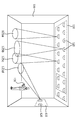
도 1은 본 발명의 하나의 실시예에 따라 구조물에 설치된 조명 시스템의 개략적인 예시이다.
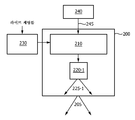
도 2는 본 발명의 하나의 실시예에 따른 조명 시스템의 개략적인 예시이다.
도 3은 본 발명의 하나의 실시예에 따라, N개의 심볼들의 반복되는 시퀀스를 포함하는 코드의 개략적인 예시이다.
도 4는 본 발명의 하나의 실시예에 따른 검출 시스템의 개략적인 예시이다.
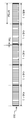
도 5는 본 발명의 하나의 실시예에 따라, 4개의 심볼들의 반복되는 시퀀스를 포함하는 예로 든 코드, 및 그러한 코드에 적절한 카메라의 프레임들 내의 예로 든 단일-비트 노출 인스턴스들의 개략적인 예시들을 제공하고 있다.
도 6a는 본 발명의 하나의 실시예에 따라, 2개의 광원들이 광 기여(contribution)들을 장면에 제공하는 때에 촬상되는 이미지들의 열의 제1 이미지의 개략적인 예시이다.
도 6b는 본 발명의 하나의 실시예에 따라, 2개의 광원들이 광 기여들을 장면에 제공하는 경우에 촬상되는 이미지들의 열의 제2 이미지의 개략적인 예시이다.
도 6c는 본 발명의 하나의 실시예에 따라, 2개의 광원들이 광 기여들을 장면에 제공하는 경우에 촬상되는 이미지들의 열의 개략적인 예시이다.
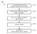
도 7은 본 발명의 하나의 실시예에 따라, N개의 심볼들의 반복되는 시퀀스를 결정하기 위한 방법 단계들의 흐름도이다.
도 8은 본 발명의 하나의 실시예에 따라, 제1 광원의 광 출력을 포함하는 장면 내의 하나의 선택된 물리적 위치에 대응하는 획득된 이미지들의 열의 픽셀들의 시퀀스의 개략적인 예시이다.
도 9는 본 발명의 하나의 실시예에 따라, 4개의 심볼들의 반복되는 시퀀스를 포함하는 예로 든 코드, 및 그러한 코드에 적절한 카메라의 프레임들 내의 예로 든 복수-비트 노출 인스턴스들의 개략적인 예시들을 제공한다.
도 10은 본 발명의 하나의 실시예에 따라, N개의 심볼들의 반복되는 시퀀스를 포함하는 예로 든 코드, 및 카메라 외부의 셔터를 동작시키는데 이용되는 예로 든 스위칭 신호의 개략적인 예시들을 제공한다.1 is a schematic illustration of a lighting system installed in a structure according to one embodiment of the invention.
2 is a schematic illustration of a lighting system according to one embodiment of the invention.
3 is a schematic illustration of a code including a repeated sequence of N symbols, in accordance with one embodiment of the present invention.
4 is a schematic illustration of a detection system according to one embodiment of the invention.
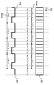
5 provides schematic examples of an example code that includes a repeated sequence of four symbols, and example single-bit exposure instances in frames of a camera appropriate to such code, in accordance with one embodiment of the present invention. Doing.
6A is a schematic illustration of a first image of a column of images taken when two light sources provide light contributions to a scene, in accordance with one embodiment of the present invention.
6B is a schematic illustration of a second image of a column of images taken when two light sources provide light contributions to a scene, in accordance with one embodiment of the present invention.
6C is a schematic illustration of a row of images taken when two light sources provide light contributions to a scene, in accordance with one embodiment of the present invention.
7 is a flowchart of method steps for determining a repeated sequence of N symbols, in accordance with one embodiment of the present invention.
8 is a schematic illustration of a sequence of pixels of a column of acquired images corresponding to one selected physical location in a scene that includes the light output of a first light source, in accordance with one embodiment of the present invention.
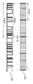
9 provides example code including a repeating sequence of four symbols, and example multi-bit exposure instances in frames of a camera appropriate to such code, in accordance with one embodiment of the present invention. do.
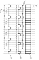
10 provides schematic examples of an example code including a repeated sequence of N symbols, and an example switching signal used to operate a shutter outside the camera, in accordance with one embodiment of the present invention.
이하의 설명에서, 본 발명의 더 철저한 이해를 제공하기 위해 다수의 특정 세부사항들이 제시되어 있다. 그러나, 본 기술분야의 숙련자에게는, 본 발명이 이들 특정 세부사항들의 하나 이상이 없이도 실시될 수 있다는 것은 자명할 것이다. 다른 예들에서, 본 발명을 모호하게 하는 것을 피하기 위해 공지된 특징들은 기재되지 않았다.In the following description, numerous specific details are set forth in order to provide a more thorough understanding of the present invention. However, it will be apparent to one skilled in the art that the present invention may be practiced without one or more of these specific details. In other instances, well known features have not been described in order to avoid obscuring the present invention.
도 1은 설치된 조명 시스템(110)을 구비하는 구조물(100) - 이 경우에는 방 - 을 도시하고 있다. 조명 시스템(110)은 하나 이상의 광원들(120) 및 광원들(120)을 제어하는 하나 이상의 컨트롤러들(도 1에는 도시되지 않음)을 포함한다. 전기 신호로 구동되는 경우에, 광원들(120)은 구조물(100)의 부분들을 조명하고, 다양한 광원들(120)로부터의 조명 기여들은 풋프린트들(125a-125d)로서 도시되어 있다. 광원들(120)은 고압/저압 기체 방전 소스들, 무기/유기 발광 다이오드들, 레이저 다이오드들, 백열 소스들, 또는 할로겐 소스들을 포함할 수 있다. 조명 시스템(110)은 사용자가 광원들(120)을 제어할 수 있도록 허용하는 원격 컨트롤(130)을 더 포함할 수 있다.FIG. 1 shows a
도 2는 본 발명의 하나의 실시예에 따른 조명 시스템(200)의 개략적인 예시이다. 조명 시스템(200)은 도 1에 예시된 구조물(100)의 조명 시스템(110)으로 이용될 수 있다. 도시된 바와 같이, 조명 시스템(200)은 적어도 시스템 컨트롤러(210) 및 제1 광원(220-1)을 포함하고, 라이트 세팅들에 따라 광 출력(205)을 생성하도록 구성된다. 다른 실시예들에서, 조명 시스템은 추가적인 광원들, 및 선택적으로는 추가적인 광원들의 각각을 개별적으로 제어하는 추가적인 컨트롤러들을 포함할 수 있다. 다르게는, 단일 컨트롤러가 복수의 광원들을 제어하도록 구성될 수 있다.2 is a schematic illustration of a
조명 시스템(200)은 이하와 같이 동작하도록 구성된다. 도 2에 도시된 바와 같이, 조명 시스템(200)에 대한 라이트 세팅들은 드라이브 신호 발생기(230)(선택적으로는 조명 시스템(200) 내에 포함될 수 있음)에 제공된다. 라이트 세팅들은 예를 들면 광 전력(예를 들어, 루멘으로 정의됨) 및 컬러의 측면에서 평균 광 출력(205)이 어떠해야 하는지를 나타낸다. 라이트 세팅들은 사용자에 의해 원격 컨트롤(130)을 통해 제공되거나, 사전 프로그래밍되어 장면 세팅을 제어하는 외부 유닛으로부터 제공될 수 있다. 다르게는, 라이트 세팅들은 사전 프로그래밍되어, 드라이브 신호 발생기(230) 내의 또는 조명 시스템(200) 내의 메모리에 저장될 수 있다. 드라이브 신호 발생기(230)는 라이트 세팅들을, 조명 시스템(200) 내의 상이한 광원들에 대한 상이한 전기 드라이브 신호들로 변환하고, 드라이브 신호들을 시스템 컨트롤러(210)에게 제공한다. 도 2에 예시된 실시예에서, 드라이브 신호 발생기(230)는 라이트 세팅들을, 제1 광원(220-1)에 대한 제1 드라이브 신호로 변환한다. 이에 대해, 시스템 컨트롤러(210)는 그들 각각의 드라이브 신호들로 상이한 광원들을 구동하여, 광 출력(205)을 생성한다. 도 2에 예시된 실시예에서, 시스템 컨트롤러(210)는 제1 드라이브 신호로 광원(220-1)을 구동하여 광 출력(225-1)을 생성하도록 구성된다. 이러한 실시예에서, 조명 시스템(200)의 광 출력(205)은 광 출력(225-1)을 포함한다.The
기재된 바와 같이, 라이트 세팅들은 조명 시스템(200)의 광 출력(205)이 예를 들면 광 컬러의 측면에서 어떠해야 하는지를 나타낸다. 광 출력(205)의 컬러 변경은 드라이브 신호 발생기(230)로부터 시스템 컨트롤러(210)에게 제공된 드라이브 신호들을 제어하는 것을 통해 조명 시스템(200) 내의 상이한 광원들(도 2에 도시되지 않은 추가적인, 선택적 광원들)을 상이하게 디밍함으로써 달성될 수 있다. 광원당 일정한 디밍 레벨을 위해, 드라이브 신호 발생기(230)로부터 시스템 컨트롤러(210)에 제공된 드라이브 신호는 펄스들의 반복된 패턴을 포함한다. 그러한 반복된 패턴은 여기에서 "드라이브 패턴"으로 지칭된다.As described, the light settings indicate what the
광원들을 디밍하기 위한 다양한 방법들은 본 기술분야의 숙련자들에게 주지되어 있고, 따라서 여기에서 상세하게 설명되지 않는다. 이들 방법들은 예를 들면 펄스폭 변조, 펄스 밀도 변조 또는 진폭 변조를 포함한다.Various methods for dimming light sources are well known to those skilled in the art and thus are not described in detail herein. These methods include, for example, pulse width modulation, pulse density modulation or amplitude modulation.
시스템 컨트롤러(210)는 데이터 소스(240)로부터 신호(245)를 수신하도록 또한 구성된다. 신호(245)는 광원(220-1)의 광 출력(225-1)에 내장될 (적어도) 데이터 비트들을 포함한다. 시스템 컨트롤러(210)는 데이터 비트들을 반복되는 시퀀스들로 배열함으로써 광 출력(225-1)에 내장될 코드를 생성하도록 구성된다. 그러한 코드의 하나의 예는 도 3에 예시되어 있다. 도시된 바와 같이, 코드(310)는 "시퀀스 1"로 도시되어 있는, N개의 심볼들(예를 들면, 비트들)의 제1 반복되는 시퀀스를 포함한다. 이하의 설명에서, 심볼들은 비트들로 지칭될 것이다. 그러나, 본 출원서에서 단어 "비트"가 이용될 때마다, 하나의 단일 심볼에 의해 표현된 복수의 비트들을 또한 포함할 수 있는 "심볼"의 더 넓은 정의가 적용된다. 하나의 예는 멀티-레벨 심볼들이고, 여기에서 데이터를 내장하는데 0 및 1뿐만 아니라 복수의 이산 레벨들도 존재한다.
코드(310)의 각 비트는 지속기간 Tbit를 가지고 있다. 그러므로, 코드 주기는 N*Tbit와 동일하다. 시퀀스는 예를 들면, 광원(220-1)의 로컬화된 식별, 그 성능들 및 현재의 라이트 세팅들, 또는 광원(220-1) 또는 조명 시스템(200)과 관련되거나 그렇지 않을 수 있는 다른 타입의 정보를 표현할 수 있다.Each bit of
하나의 실시예에서, "시퀀스 1"은 광 출력(225-1)에 내장될 모든 데이터 비트들을 포함할 수 있다. 또 하나의 실시예에서, 시스템 컨트롤러(210)는 내장될 데이터 비트들을 더 작은 길이의 세트들(즉, 패킷들)로 분할할 수 있다. 그러한 실시예에서, 광 출력(225-1)에 내장될 제1 코드는 하나의 세트의 반복되는 시퀀스(예를 들면, 반복되는 제1 패킷)를 포함할 것이고, 다음 코드는 또 하나의 세트의 반복되는 시퀀스(예를 들면, 반복되는 제2 패킷)를 포함할 것이고, 등등이다.In one embodiment, “
선택적으로는, 광 출력(225-1)에 내장될 데이터 비트들은 채널 코딩을 이용하거나(예를 들면, 컨볼루션 또는 블럭 코딩을 이용함) 사이클릭 리던던시 체크(CRC) 코드를 이용하여 인코딩될 수 있다. 이것은 비트 검출시에 에러들을 정정하거나 및/또는 검출된 데이터가 유효한지 여부를 검증하기 위해, 송신된 데이터 시퀀스들에서 리던던시를 증가시키도록 수행될 수 있다. 다르게는, 이러한 코딩은 예를 들면 광 출력(225-1)에 내장된 데이터의 가시성(visibility)을 감소시키도록, 송신된 광 신호의 스펙트럼을 형성(shape)하는데 이용될 수 있다. 후자의 접근법에서, 하나의 실시예에서, 맨체스터 인코딩이 채용될 수 있다. 이러한 인코딩 방법의 장점은, 가시적인 플릭커(flicker)를 유발하는 것들인, 광 신호들의 저주파수 컴포넌트들을 억제한다는 점이다.Optionally, data bits to be embedded in the light output 225-1 may be encoded using channel coding (e.g., using convolution or block coding) or using cyclic redundancy check (CRC) codes. . This may be performed to increase redundancy in the transmitted data sequences to correct errors in bit detection and / or to verify whether the detected data is valid. Alternatively, such coding may be used to shape the spectrum of the transmitted optical signal, for example, to reduce the visibility of the data embedded in the light output 225-1. In the latter approach, in one embodiment, Manchester encoding may be employed. The advantage of this encoding method is that it suppresses the low frequency components of the optical signals, which cause visible flicker.
하나의 실시예에서, 코드(310)는 "시퀀스 1"의 적어도 일부 발생들 사이에 삽입된 중간 시퀀스를 포함할 수 있다(도 3에 도시되지 않음). 예를 들면, 중간 시퀀스는 "시퀀스 1"의 각 발생 사이에 포함될 수 있다. 데이터 비트들이 패킷들로 분할되는 실시예에서, 그러한 중간 시퀀스는 예를 들면 송신하는 측에서 이용되는 변조 및/또는 인코딩의 타입, 및/또는 광원(220-1)의 식별과 같은 패킷과 관련된 정보를 포함하는 패킷의 헤더와 유사할 수 있다. 다르게는, 중간 시퀀스는 "시퀀스 1"의 발생들의 각 2개 또는 3개 이후에 포함될 수 있다. 여전히, 또 하나의 실시예에서, 중간 시퀀스는 간헐적이고 비-주기적인 방식으로 포함될 수 있다.In one embodiment, the
아래에 설명되는 바와 같이, 중간 시퀀스는 검출 시스템의 처리 유닛에 의해, 광원(220-1)과 검출 시스템 사이의 동기화를 도출하거나 및/또는 처리 유닛이 N개의 비트들의 제1 시퀀스의 코드 비트들을 결정하도록 허용하는 추가 정보를 처리 유닛에 제공하는데 이용될 수 있다.As described below, the intermediate sequence derives synchronization between the light source 220-1 and the detection system by the processing unit of the detection system and / or the processing unit selects code bits of the first sequence of N bits. It can be used to provide additional information to the processing unit that allows for the determination.
시스템 컨트롤러(210)는, 코드(310)에 응답하여 광원(220-1)에 인가되는 드라이브 신호를 변조함으로써, 코드(310)를 광원(220-1)의 광 출력(225-1)에 내장시킬 수 있다. 코드를 광원의 광 출력에 내장하기 위한 다양한 기술들은 본 기술분야의 숙련자들에게 주지되어 있고, 따라서 여기에서 상세하게 설명되지 않는다. 신호(245)는 다른 광원들의 광 출력에 내장될 다른 유사한 코드들을 더 포함할 수 있다. 코드들의 각각은 N개의 비트들의 상이한 반복되는 시퀀스를 포함한다.The
도 4는 본 발명의 하나의 실시예에 따른 검출 시스템(400)의 개략적인 예시이다. 도시된 바와 같이, 검출 시스템(400)은 적어도 카메라(410), 셔터(420) 및 처리 유닛(430)을 포함한다. 선택적으로는, 검출 시스템(400)은 또한 메모리(440)를 포함한다. 카메라(410)는 하나의 장면의 이미지들의 열을 획득하도록 구성된다. 셔터(420)는 이미지들이 카메라(410)에 의해 획득되는 때의 인스턴스들을 주의 깊게 타이밍하도록 구성된다(셔터(420)가 열려 있는 경우에 이미지들이 획득되고 셔터(420)가 닫혀 있는 경우에 이미지들이 획득되지 않는다). 다양한 실시예들에서, 셔터(420)는 카메라의 프레임 시간 동안에 단지 한번 열고 닫을 수 있는(즉, 하나의 프레임 내에서 소정 지속기간의 단일 노출) 카메라(410) 내부의 종래 셔터, 또는 하나의 단일 프레임 동안에 복수회 열고 닫을 수 있는 카메라 전방에 배치된 전자 셔터 중 어느 하나를 포함할 수 있다.4 is a schematic illustration of a
시나리오 1: 프레임당 단일-비트 노출Scenario 1: single-bit exposure per frame
우선, 조명 시스템(200)은 2개의 광원들이 하나의 특정 장면에 광 기여를 제공할 수 있도록 하는 것인 예로 든 시나리오를 고려하자. 그 장면은 도 1에 예시된 구조물(100)의 플로어의 일부이고, 제1 광원은 그 장면 내에서(즉, 플로어 상에서) 풋프린트(125b)을 가지는 도 1에 예시된 광원들(120)의 하나이며, 제2 광원은 그 장면 내에서 풋프린트(125c)을 가지는 도 1에 예시된 광원들(120) 중 하나인 것으로 간주한다. 제1 및 제2 광원들의 광 출력들에 내장된 각각의 코드들은 N개의 비트들의 상이한 반복되는 시퀀스들을 포함한다.First, consider the example scenario where the
단순성을 위해, 제1 광원의 광 출력에 내장될 데이터는 단지 4 비트들만을 포함하는 것으로 간주한다. 이들 4개의 비트들의 반복되는 시퀀스를 포함하는 코드는 도 5에서 코드(510)로 도시되어 있다(즉, N개의 비트들의 제1 반복되는 시퀀스는 4 비트들의 시퀀스를 포함한다). 도시된 바와 같이, 비트들의 각각은 지속기간 Tbit를 가지고 있다. 그러므로, 코드 주기는 4*Tbit와 동일하다. 또한, 시퀀스의 개별적인 비트들, 비트들 c11, c12, c13, c14는 도 5에 신호(520)로 예시된, 0, 1, 0, 및 0을 각각 포함하는 것으로 간주한다. 신호(520)는 도 2에 기재된 신호(245)에 포함될 수 있다.For simplicity, the data to be embedded in the light output of the first light source is considered to contain only 4 bits. Code that includes a repeated sequence of these four bits is shown as
상기 설명된 바와 같이, 데이터는 제1 광원을 코드(510)에 응답하여 변조된 드라이브 신호로 구동함으로써 제1 광원의 광 출력에 내장된다. 다양한 실시예들에서, 시스템 컨트롤러(210)는 예를 들면 펄스폭 변조(PWM), 펄스 위치 변조, 펄스 밀도 변조 또는 진폭 변조를 이용하여 이진 또는 멀티레벨 변조를 통해 드라이브 신호를 변조함으로써 변조된 드라이브 신호를 생성할 수 있다. 예를 들면, PWM을 이용하여 신호(520)로부터 0의 이진값을 내장하기 위해, 시스템 컨트롤러(210)는 드라이브 신호 내의 드라이브 패턴을 양 a만큼 더 좁게 만들어 신호(520)로부터 "0"의 이진값을 내장할 수 있고, 시스템 컨트롤러(210)는 드라이브 신호 내의 또 하나의 드라이브 패턴을 양 b만큼 더 넓게 만들어 신호(520)로부터 "1"의 이진값을 내장할 수 있다. 양 a 및 양 b 사이의 비율을 신호(520)에서 1과 0의 개수 사이의 비율과 동일하게 함으로써, 변조된 드라이브 신호의 시간 평균이 원래의 드라이브 신호의 것과 동일하게 유지되기 때문에, 조명 시스템의 광 출력에서 데이터를 내장하는 것은 사람 눈에 보이지 않게 될 수 있다. 본 기술분야의 숙련자들이라면, 신호(520)에 종속하여 드라이브 신호를 변조하여 데이터를 조명 시스템의 광 출력에 내장하기 위한 다른 방법들을 알고 있을 것이다.As described above, data is embedded in the light output of the first light source by driving the first light source with a drive signal modulated in response to the
유사하게, 제2 광원의 광 출력에 내장된 데이터가 4 비트들, c21, c22, c23, c24를 포함하는 것으로 간주한다. 다시, 비트들의 각각은 지속기간 Tbit를 가지고 있고, 따라서 코드 주기는 4*Tbit와 동일하다. 데이터의 비트들이 제2 광원의 광 출력에 내장될 수 있는 방법에 관한 상기 설명은 적용가능하고, 따라서 간략함을 위해 반복되지 않는다.Similarly, it is assumed that the data embedded in the light output of the second light source includes four bits, c 21 , c 22 , c 23 , c 24 . Again, each of the bits has a duration T bit , so the code period is equal to 4 * T bits . The above description of how the bits of data can be embedded in the light output of the second light source is applicable and thus is not repeated for simplicity.
검출 시스템(400)은 제1 광원의 광 출력에 내장된 데이터의 비트들을 결정하기 위해 이하의 방식으로 동작하도록 구성될 수 있다.
우선, 카메라(410)는 장면의 이미지들의 열을 획득하도록 구성되고, 여기에서 장면은 그 장면의 적어도 일부가 제1 광원의 광 출력을 포함하도록 선택된다. 그를 위해, 카메라의 프레임 시간은 코드 주기보다 1 비트 크도록, 즉 5*Tbit가 되도록 설정될 수 있고, 카메라의 노출은 코드 주기의 1 비트의 지속기간, 즉 Tbit와 동일한 지속기간을 가지는 단일 노출 인스턴스를 포함하도록 설정될 수 있다. 또한, 카메라(410)는 각 프레임의 제1 시간 주기 Tbit 동안에 이미지를 획득하도록 구성될 수 있다. 이러한 방식으로 구성된 카메라(410)의 노출은 도 5에 라인(530)으로 예시되어 있다.First, the
이미지가 촬상되는 경우에, 카메라는 하나의 장면 내의 모든 위치들에서 조명 시스템의 전체 광 출력의 세기들을 획득한다. 본 어플리케이션에서, 용어 (광 출력의) "세기"가 이용될 때마다, 예를 들면 광 컬러, 컬러 온도, 광 스펙트럼, 및 광 세기의 변경과 같은 "세기의 파생물"이 또한 포함된다고 생각된다. 이미지는 통상적으로 복수의 픽셀들로 분할되고, 여기에서 각 픽셀은 그 장면 내의 상이한 물리적 위치에서 조명 시스템의 전체 광 출력의 세기를 나타낸다. 현재의 시나리오에서, 조명 시스템의 전체 광 출력은 제1 광원으로부터의 광 기여 및 제2 광원으로부터의 광 기여를 포함한다.When the image is imaged, the camera acquires intensities of the overall light output of the lighting system at all locations in one scene. In this application, whenever the term "intensity" (light output) is used, it is contemplated to include "derivatives of intensity" such as changes in light color, color temperature, light spectrum, and light intensity as well. An image is typically divided into a plurality of pixels, where each pixel represents the intensity of the overall light output of the lighting system at different physical locations in the scene. In the current scenario, the total light output of the illumination system includes light contribution from the first light source and light contribution from the second light source.
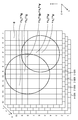
각 이미지는 x-방향으로 10개의 픽셀들 및 y-방향으로 15개의 픽셀들을 가지는 150개의 픽셀들의 2D 그리드로 분할되는 것으로 간주한다. 카메라(410)의 노출 시간이 코드의 단일 코드 비트와 동일하게 설정되기 때문에, 이미지의 특정 픽셀에서의 세기는 이미지가 촬상되는 때에, 제1 광원의 광 출력에 인코딩된 코드의 비트의 값, 및 제2 광원의 광 출력에 인코딩된 코드의 비트의 값에 의해 영향을 받는다. 그러한 제1 이미지는 도 6a에 도시되어 있다(이러한 이미지는 도 5에 예시된 프레임 1에 대응한다). 그 장면 내의 제1 광원의 풋프린트는 원(610)으로 도시되어 있고, 제2 광원의 풋프린트는 원(620)으로 도시되어 있다. 제1 광원의 광 출력이 코드 비트 c11로 변조되고 제2 광원의 광 출력이 코드 비트 c21로 변조되는 경우에 제1 이미지(600-1)가 촬상되기 때문에, 각 픽셀 (x,y)에서의 세기 Ix ,y는 이하와 같이 계산될 수 있다.Each image is considered to be divided into a 2D grid of 150 pixels with 10 pixels in the x-direction and 15 pixels in the y-direction. Since the exposure time of the
Ix ,y = Ax ,y·c11 + Bx ,y·c21 I x , y = A x , yc 11 + B x , yc 21
여기에서, Ax,y 및 Bx,y는 제1 및 제2 광원들에 인가된 드라이브 신호들이 특정 코드 비트로 변조되지 않은 경우에 제1 및 제2 광원들의 광 출력의 세기들이 가지게 될 각각의 값들이다. 그러므로, 도 6a에 도시된 바와 같이, 예를 들면 픽셀(7,6)에서의 세기는 (A7,6·c11 + B7,6·c21)과 동일하다. 또한, 도 6a에 도시된 바와 같이, 예를 들면 픽셀(4,5)에서의 세기는 A4,5·c11과 동일하고, 픽셀 (5,5)에서의 세기는 A5,5·c11과 동일한데, 그 이유는 제2 광원은 이들 픽셀들에 의해 표현된 장면의 부분들에 대한 어떠한 광 기여도 제공하지 않기 때문이고(이들 픽셀들은 풋프린트(620)의 외부에 있다), 즉 B4,5 = B5,5 = 0이다. 유사하게, 예를 들면 픽셀(7,9)에서의 세기는 B7,9·c21과 동일하고, 픽셀 (8,12)에서의 세기는 B8,12·c21과 동일한데, 그 이유는 제1 광원은 이들 픽셀들에 의해 표현된 장면의 부분들에 대한 어떠한 광 기여도 제공하지 않기 때문이고(이들 픽셀들은 풋프린트(610)의 외부에 있다), 즉 B7,9 = B8,12 = 0이다. 예를 들면 픽셀(9,2)에서의 세기는, 제1 또는 제2 광원 어느 것도 이러한 픽셀에 의해 표현된 장면의 부분에 어떠한 광 기여도 제공하지 않기 때문에(이러한 픽셀은 풋프린트(610 및 620)의 외부에 있다), 제로와 동일한 것으로 도시되어 있다.Where A x, y and B x, y are the respective intensities of the light outputs of the first and second light sources if the drive signals applied to the first and second light sources are not modulated with specific code bits. Values. Therefore, as shown in FIG. 6A, for example, the intensity at the
노출(530)로부터 알 수 있는 바와 같이, 장면의 이미지들의 열의 제2 이미지는 카메라(410)의 프레임 2 동안에 얻어진다. 제2 이미지는 도 6b에서 이미지(600-2)로 도시되어 있다. 동일한 장면의 이미지가 촬상되므로, 풋프린트들(610 및 620)은 제1 이미지에서와 동일하게 유지된다. 제1 광원의 광 출력이 코드 비트 c12로 변조되고 제2 광원의 광 출력이 코드 비트 c22로 변조되는 경우에 이미지(600-2)가 촬상되기 때문에, 각 픽셀(x,y)에서의 세기는 이하와 같이 계산될 수 있다.As can be seen from the
Ix ,y = Ax ,y·c12 + Bx ,y·c22 I x , y = A x , yc 12 + B x , yc 22
그러므로, 도 6b에 도시된 바와 같이, 예를 들면 픽셀(7,6)에서의 세기는 (A7,6·c12 + B7,6·c22)와 동일하다. 또한, 도 6a에 도시된 바와 같이, 예를 들면 픽셀(4,5)에서의 세기는 A4,5·c12와 동일하고, 픽셀(5,5)에서의 세기는 A5,5·c12와 동일하며, 픽셀(7,9)에서의 세기는 B7,9·c22와 동일하고, 픽셀(8,12)에서의 세기는 B8,12·c22와 동일하다. 다시, 예를 들면 픽셀(9,2)에서의 세기는, 제1 또는 제2 광원들 어느 것도 이러한 픽셀에 의해 표현되는 장면의 부분에 어떠한 광 기여도 제공하지 않기 때문에, 제로와 동일한 것으로 도시되어 있다. Therefore, as shown in FIG. 6B, for example, the intensity at the pixels 7 and 6 is (A 7,6 · c 12). + B 7,6 · c 22 ). Further, as shown in FIG. 6A, for example, the intensity at
유사한 방식으로, 프레임들 3 및 4에서, 카메라(410)는 이미지들의 열의 제3 이미지(600-3) 및 제4 이미지(600-4)를 각각 획득한다. 다시, 카메라(410)의 노출 시간 및 프레임 시간이 내장된 코드들에 대해 구성되는 방식으로 인해, 제1 및 제2 광원들의 광 출력들이 코드 비트들 c13 및 c23로 각각 변조되는 경우에 제3 이미지가 촬상되고, 제1 및 제2 광원들의 광 출력들이 코드 비트들 c14 및 c24로 각각 변조되는 경우에 제4 이미지가 촬상된다. 이미지들(600-1, 600-2, 600-3, 및 600-4)의 열은 도 6c에 도시되어 있고, 여기에서 상이한 이미지들은 t-방향(여기에서, "t"는 "시간"을 나타낸다)으로 확장되도록 도시되어 있고, 이는 이미지들이 동일한 장면이지만 상이한 시각들에서 촬상되어 있다는 것을 나타낸다.In a similar manner, in
이미지들(600-1 내지 600-4)의 열을 획득했으므로, 처리 유닛(430)은 이미지들의 열을 처리하여, 제1 광원의 광 출력에 내장된 N개의 비트들의 제1 반복되는 시퀀스를 결정할 수 있다. 도 7은 본 발명의 하나의 실시예에 따라, N개의 비트들의 제1 반복되는 시퀀스를 결정하기 위한 방법(700)의 흐름도를 예시하고 있다. 방법 단계들은 도 4와 관련하여 설명되고 있지만, 본 기술분야의 숙련자들이라면, 방법 단계들을 임의의 순서로 수행하도록 구성된 임의의 시스템이 본 발명의 범주 내에 있다는 것을 잘 알고 있을 것이다.Having obtained a column of images 600-1 through 600-4, the
방법(700)은 단계 710으로 시작될 수 있고, 여기에서 처리 유닛(430)은 제1 광원의 광 출력만을 포함하는 장면 내의 물리적 위치에 대응하는 이미지들(600-1 내지 600-4)의 열 내에서 픽셀들의 시퀀스를 선택하도록 구성된다.The
그 장면 내에서 특정 물리적 위치에 대응하는 이미지들(600-1 내지 600-4)의 열 내의 픽셀들의 시퀀스를 예시하기 위해, 그 장면 내의 선택된 물리적 위치는 이미지들(600-1 내지 600-4) 상의 픽셀(4,5)에 대응하는 위치인 것으로 간주한다. 그리고나서, 그 위치에 대응하는 획득된 열의 픽셀들의 시퀀스는 이미지들의 각각으로부터 픽셀들(4,5)을 포함한다. 이러한 시퀀스는 도 8에서 시퀀스(810)로 도시되어 있다. 시퀀스(810)는 제1 이미지(600-1)로부터의 픽셀(4,5)(픽셀(820-1)로 도시됨), 제2 이미지(600-2)로부터의 픽셀(4,5)(픽셀(820-2)로 도시됨), 제3 이미지(600-3)로부터의 픽셀(4,5)(픽셀(820-3)로 도시됨), 및 제4 이미지(600-4)로부터의 픽셀(4,5)(픽셀(820-4)로 도시됨)을 포함한다. 도 8에 도시된 바와 같이, 픽셀들(820-1 내지 820-4)에서의 세기들은 각각 A4,5·c11, A4,5·c12, A4,5·c13, 및 A4,5·c14와 동일하다.To illustrate a sequence of pixels in a column of images 600-1 through 600-4 corresponding to a particular physical location within the scene, the selected physical location within the scene is selected by images 600-1 through 600-4. It is assumed to be a position corresponding to the
하나의 실시예에서, 그 장면 내의 특정 물리적 위치에 대응하는 픽셀들의 시퀀스가 단일(제1) 광원의 광 출력만을 포함한다는 결정은 이하의 방식으로 수행될 수 있다.In one embodiment, the determination that the sequence of pixels corresponding to a particular physical location in the scene includes only the light output of a single (first) light source may be performed in the following manner.
시스템 컨트롤러(210)는 때때로 제1 광원의 광 출력에 내장될 코드에 하나의 중간 시퀀스를 포함시키고, 또 하나의 중간 시퀀스를, 제2 광원의 광 출력에 내장될 코드에 포함시킬 수 있으며, 여기에서 처리 유닛(430)은 양쪽 중간 시퀀스들에 액세스할 수 있다.The
중간 시퀀스들의 각각은 예를 들면 특정 광원의 식별자와 같은 일종의 식별자를 포함할 수 있다. 상기 설명된 이같은 방식으로 식별될 수 있는 상이한 광원들의 개수는 중간 시퀀스의 길이에 종속된다. 예를 들면, M개의 이진 값들의 반복되는 시퀀스를 포함하는 동기형 월시-아다마르(Walsh-Hadamard) 코드에 대해, M개의 상이한 광원들이 식별될 수 있고, 이는 처리 유닛(430)이 M개의 상이한 광원들중 임의의 하나의 광 기여가 하나의 장면 내의 특정 위치에서 존재하는지 여부를 결정할 수 있고, 선택적으로는 그러한 광 기여의 크기를 결정할 수 있다는 것을 의미한다. 각 프레임에서 단일 비트-길이 노출 인스턴스를 가지도록 구성된 종래의 50Hz 카메라(즉, 카메라는 초당 50개의 이미지들을 촬상할 수 있다)를 이용하는 경우에, 내장된 코드의 50-비트 중간 시퀀스를 분해하는데 필요한 이미지들의 열은 1초 내에 획득될 수 있다.Each of the intermediate sequences may include some kind of identifier, such as for example the identifier of a particular light source. The number of different light sources that can be identified in this way as described above depends on the length of the intermediate sequence. For example, for a synchronous Walsh-Hadamard code that includes a repeated sequence of M binary values, M different light sources can be identified, which causes the
하나의 실시예에서, 조명 시스템(200)은 중간 시퀀스들을 처리 유닛(430)에게 직접 제공할 수 있다. 또 하나의 실시예에서, 검출 시스템(400)은 중간 시퀀스들을 저장하는 메모리(440)를 포함할 수 있다. 또 다른 하나의 실시예에서, 검출 시스템(400)은 (무선으로) 수신된 광 신호들로부터 중간 시퀀스들을 얻도록 구성될 수 있다. 대안으로, 처리 유닛(430)은 상기 설명된 수단들 중 임의의 하나에 의해, 내장된 코드들 각각에 포함된 중간 시퀀스들 자체들이 아니라, 그 파생물들(즉, 그로부터 중간 시퀀스들이 획득될 수 있는 파라미터들)을 얻을 수 있다. 예를 들면, 처리 유닛(430)은 특정 주지된 시퀀스의 길이 또는 가능한 시퀀스들의 세트 중 하나를 참조하는 표시자 번호를 얻을 수 있다. 그리고나서, 중간 시퀀스들은 처리 유닛(430)에 의해 재생성될 수 있고, 잠재적으로는 검출 시스템(400)에 제공되는 통신 양을 감소시킨다. 또 하나의 실시예에서, 중간 시퀀스들을 기술하는 파라미터들은 수신된 광 신호들로부터 추출될 수 있다.In one embodiment, the
중간 시퀀스들에 액세스할 수 있으므로, 처리 유닛(430)은 그 장면 내의 선택된 물리적 위치에 대응하는 획득된 이미지들의 열의 픽셀들의 시퀀스를 중간 시퀀스들의 각각과 상관하도록 구성될 수 있다. 여기에서 유의해야 할 점은, 코드(510)가 예를 들면 시퀀스 1의 각 발생 이전 또는 이후에 포함되는 M개의 비트들의 중간 시퀀스들을 더 포함하는 실시예에서, 카메라(410)에 의해 획득되는 이미지들의 개수는 상기 설명된 바와 같이, 단지 4개의 이미지들(N=4이므로) 대신에 적어도 (4+M)개의 이미지들일 것이라는 점이다. 코드(510)가 예를 들면 시퀀스 1의 각각의 제2 발생 이전에 또는 이후에 포함되는 M개의 비트들의 중간 시퀀스들을 더 포함하는 실시예에서, 카메라(410)에 의해 획득되는 이미지들의 개수는 적어도 (2*N+M)개의 이미지들일 것이다. 본 기술분야의 숙련자들이라면, 내장된 코드의 모든 비트들을 분해하기 위해 카메라(410)로 획득하는데 필요한 이미지들의 최소 개수의 유사한 변동들을 이해할 수 있을 것이다. 중간 시퀀스를 가지는 그러한 실시예들에서, 획득된 이미지들의 열의 픽셀들의 시퀀스는, 시퀀스가 4개보다 많은 값들을 포함할 것이기 때문에, 도 8에 예시된 시퀀스(810)와는 상이할 것이다. 특히, 그것은 각 획득된 이미지로부터 하나의 값: 예를 들면, 상기 설명된 제1 실시예에 대해 (4+M)개의 값들 및 상기 설명된 제2 실시예에 대해 (8+M)개의 값들을 포함할 것이다. 유사하게, 카메라(410)의 프레임 시간은 최소 개수의 상이한 이미지들을 획득하는데 적절하도록 설정될 것이다 - 프레임 시간은 상기 설명된 제1 실시예에 대해 (4+1+M)*Tbit로, 그리고 상기 설명된 제2 실시예에 대해 (8+1+M)*Tbit로 설정될 수 있다.Since the intermediate sequences can be accessed, the
그 장면 내의 선택된 물리적 위치에 대응하는 획득된 이미지들의 열의 픽셀들의 시퀀스와 제1 광원의 광 출력에 내장된 중간 시퀀스(여기에서는 "제1 중간 시퀀스"로 지칭됨)와의 상관의 결과로서, 적어도 하나의 피크를 가지는 상관 출력이 생성된다. 상관 출력은 통상적으로 다수의 "피크들"을 포함하고, 여기에서 일부 피크들은 다른 것들보다 더 작고 상관 프로세스의 아티팩트들을 나타낸다. 그러한 작은 피크들은 여기에서 "서브피크들"로 지칭되고, 용어 "피크"는 여기에서 그 장면 내의 선택된 물리적 위치에 대응하는 획득된 이미지들의 열의 픽셀들의 시퀀스 내에 특정 중간 시퀀스의 존재를 나타내는 상관 출력에서의 피크를 기술하는데 이용된다. 이러한 피크는 상관 출력에서 서브피크들보다 명백하게 더 높을 것이고, 본 기술분야의 숙련자라면 그러한 피크를 용이하게 식별할 수 있다. 그러므로, 그 장면 내의 선택된 물리적 위치에 대응하는 획득된 이미지들의 열의 픽셀들의 시퀀스와 제1 중간 시퀀스와의 상관에 기초하여, 처리 유닛(430)은 상관 출력이 피크를 포함하는 경우에, 제1 광원의 광 기여가 그 장면 내의 선택된 물리적 위치에 존재한다고 결정할 수 있다. 그 장면 내의 선택된 위치에 대응하는 획득된 이미지들로부터의 픽셀들의 시퀀스를 제1 중간 시퀀스와 상관시킴으로써, 그 장면 내의 임의의 다른 선택된 물리적 위치에 대해 유사한 상관이 수행될 수 있다.At least one as a result of the correlation of the sequence of pixels of the column of acquired images corresponding to the selected physical location within the scene with an intermediate sequence embedded herein in the light output of the first light source (herein referred to as a "first intermediate sequence") A correlation output with a peak of is generated. The correlation output typically includes a number of "peaks", where some peaks are smaller than others and represent artifacts of the correlation process. Such small peaks are referred to herein as "subpeaks" and the term "peak" herein refers to the presence of a particular intermediate sequence in the sequence of pixels of the column of acquired images that corresponds to the selected physical location in the scene. It is used to describe the peak of. This peak will be clearly higher than the subpeaks in the correlation output, and those skilled in the art can readily identify such a peak. Therefore, based on the correlation between the first intermediate sequence and the sequence of pixels of the column of acquired images corresponding to the selected physical location in the scene, the
한편, 그 장면 내의 선택된 물리적 위치에 대응하는 획득된 이미지들의 열의 픽셀들의 시퀀스와 제1 광원의 광 출력에 내장된 중간 시퀀스(여기에서는 "제2 중간 시퀀스"로 지칭됨)와의 상관의 결과로서, 도 6a에 도시된 바와 같이, 제2 광원은 픽셀(4,5)로의 어떠한 또는 적어도 무시가능한 광 기여도 제공하지 못하기 때문에, 어떠한 피크도 가지지 않는 상관 출력이 생성된다. 그러므로, 처리 유닛(430)은 획득된 이미지들의 열로부터의 픽셀들(4,5)의 시퀀스가 단일(제1) 광원의 광 출력만을, 또는 주로 포함한다고 결정할 수 있다.On the other hand, as a result of the correlation of the sequence of pixels of the column of acquired images corresponding to the selected physical location in the scene with the intermediate sequence embedded in the light output of the first light source (herein referred to as the "second intermediate sequence"), As shown in FIG. 6A, since the second light source does not provide any or at least negligible light contribution to the
예를 들면, 처리 유닛(430)이, 픽셀들(7,6)의 시퀀스를 제1 및 제2 중간 시퀀스들의 각각과 상관시킴으로써, 예를 들면 획득된 이미지들의 열 내의 픽셀들(7,6)의 시퀀스가 단일(제1) 광원의 광 출력만을 포함하는지 여부를 결정하는 것으로 시작했던 경우에, 양쪽 상관 출력들은 피크를 포함할 것이다. 이들 상관 출력들의 각각에서의 피크는 픽셀(7,6)에 대응하는 장면 내의 물리적 위치의 양쪽 광원들의 광 출력의 존재를 나타낼 것이다. 그리고나서, 처리 유닛(430)은 단지 제1 광원만의 광 출력을 포함하는 획득된 이미지들의 열의 픽셀들의 적어도 하나의 시퀀스가 발견될 때까지, 또 하나의 픽셀들의 시퀀스를 분석하도록 진행할 것이다.For example, the
그 장면 내의 특정 물리적 위치에 대응하는 픽셀들의 시퀀스가 단일(제1) 광원의 광 출력만을 포함한다고 결정하는 그러한 실시예에 대해, 중간 시퀀스들은 양호한 자동상관 속성들을 가지고 있는 시퀀스들을 포함할 수 있다. 모든 광원에 고유한 중간 시퀀스가 할당되는 시스템에서 이용되는 경우에, 이들 시퀀스들은 양호하게는 직교한다. 이것의 예들은 월시-아다마르 시퀀스들일 것이고, 여기에서 중간 시퀀스의 길이는 중간 시퀀스에 할당되는 광원들의 개수와 동일하다. 그러나, 이들 시퀀스들은 통상적으로 동기형 동작을 필요로 하고, 이는 추가적인 복잡성 때문에 항상 요구되는 것은 아니다. 그러므로, 중간 시퀀스들의 또 하나의 바람직한 속성은 양호한 교차-상관 속성들, 즉 시퀀스들 사이의 높은 자동상관 및 낮은 교차-상관을 가지고 있는 것이다. 그러한 시퀀스들의 예들은 의사-랜덤 시퀀스들, 선형 피드백 시프트 레지스터들에 의해 생성된 시퀀스들, 또는 코드 분할 다중 액세스 통신 시스템들에 이용될 수 있는 다른 시퀀스들을 포함한다.For those embodiments in which the sequence of pixels corresponding to a particular physical location in the scene determines only the light output of a single (first) light source, the intermediate sequences may include sequences having good autocorrelation properties. When used in a system where an intermediate sequence unique to every light source is assigned, these sequences are preferably orthogonal. Examples of this would be Walsh-Hadamard sequences, where the length of the intermediate sequence is equal to the number of light sources assigned to the intermediate sequence. However, these sequences typically require synchronous operation, which is not always required because of the additional complexity. Therefore, another preferred attribute of intermediate sequences is to have good cross-correlation properties, ie high autocorrelation and low cross-correlation between sequences. Examples of such sequences include pseudo-random sequences, sequences generated by linear feedback shift registers, or other sequences that may be used in code division multiple access communication systems.
또 다른 하나의 실시예에서, 모든 광원들에는 고유 스위칭 주파수들이 할당되고, 이들은 식별 코드로서 역할한다. 또한, 이들은 낮은 교차-상관 및 높은 자동-상관을 생성한다.In another embodiment, all light sources are assigned unique switching frequencies, which serve as identification codes. In addition, they produce low cross-correlation and high auto-correlation.
본 기술분야의 숙련자들이라면, 여기에 기재된 모든 시나리오들에 대해, 이미지들의 열들을 처리하여 특정 광원의 광 기여가 그 장면 내의 선택된 물리적 위치에서 존재하는지 여부를 결정하기 위한 다른 방법들이 처리 유닛(430)에 의해 수행될 수 있다는 것을 알고 있을 것이다. 예를 들면, 처리 유닛(430)은 예를 들면 상이한 중간 시퀀스들에 대응하는 다양한 픽셀들의 시퀀스들을 생성하고, 이들 시퀀스들 중 어느 것이 선택된 물리적 위치에 대응하는 획득된 이미지들의 열의 픽셀들의 시퀀스와 매칭하는지를 결정할 수 있고, 이는 예를 들면 최대 우도 검색으로 수행될 수 있다. 다른 방법들도 또한 구상될 수 있다.Those skilled in the art will, for all scenarios described herein, provide other methods for processing the columns of images to determine whether a light contribution of a particular light source exists at a selected physical location within the scene. It will be appreciated that it can be performed by For example, the
또 하나의 실시예에서, 그 장면 내의 특정 물리적 위치에 대응하는 픽셀들의 시퀀스가 주로 단일(제1) 광원의 광 출력을 포함한다는 결정은 비트의 시퀀스에 내장된 CRC를 이용하여 수행될 수 있고, 이는 픽셀들의 시퀀스가 제1 광원의 광 기여들만을, 또는 주로 포함하는지 여부를 결정하는데 이용된다. 이를 결정하기 위해, 도 7의 프로세스가 이하에 더 설명되는 바와 같이 적용될 수 있다. 그리고나서, CRC는 데이터가 정확하게 검출되는지 여부를 검증하는데 이용된다. 이것은 제1 광원의 광 기여가 너무 약한 경우, 그 픽셀에서 제1 광원의 어떠한 광 기여도 존재하지 않는 경우, 또는 그 픽셀에서 복수의 광원들로부터 강한 광 기여들이 존재하는 경우에는 적용되지 않을 가능성이 있다.In another embodiment, the determination that the sequence of pixels corresponding to a particular physical location in the scene mainly comprises the light output of a single (first) light source may be performed using a CRC embedded in the sequence of bits, This is used to determine whether the sequence of pixels includes only or mainly the light contributions of the first light source. To determine this, the process of FIG. 7 can be applied as described further below. The CRC is then used to verify whether the data is detected correctly. This is unlikely to apply if the light contribution of the first light source is too weak, if there is no light contribution of the first light source at that pixel, or if there are strong light contributions from a plurality of light sources at that pixel. .
그 장면 내의 다양한 특정 물리적 위치들에 대응하는 픽셀들의 시퀀스들이 제1 광원의 광 출력만을, 또는 주로 포함하는지 여부를 결정하는 동안에, 복수의 픽셀들에서 동일한 데이터 스트림(제1 광원의 광 출력에 대응함)이 검출될 가능성이 있다. 하나의 실시예에서, 이들 픽셀들로부터의 신호들은 제1 광원의 광 출력에 내장된 데이터의 개별적인 비트들의 후속 결정 동안에 조합될 수 있다. 다르게는, 제1 광원의 광 출력에 내장되는 데이터의 제1 패킷에서 성공적인 검출을 산출하는 단지 소수의 픽셀들의 선택이 이하의 패킷들의 검출에 이용될 수 있다. 제1 광원의 광 출력만을 포함하지 않는 픽셀들은 이하의 단계들에서 무시될 수 있다.While determining whether sequences of pixels corresponding to various specific physical locations within the scene include only or primarily the light output of the first light source, the same data stream (corresponding to the light output of the first light source) in the plurality of pixels. ) May be detected. In one embodiment, signals from these pixels may be combined during subsequent determination of individual bits of data embedded in the light output of the first light source. Alternatively, the selection of only a few pixels that yields a successful detection in the first packet of data embedded in the light output of the first light source can be used for the detection of the following packets. Pixels that do not include only the light output of the first light source can be ignored in the following steps.
또 다른 하나의 실시예에서, 상이한 광원들이 상이한 파장들의 광 출력을 생성하는 경우에, 검출 시스템(400)은 이미지들의 열을 획득할 때 특정 파장(또는 파장들의 범위)의 광만을 통과시키도록 적응된 컬러 필터를 이용함으로써, 그 장면 내의 특정 물리적 위치에 대응하는 픽셀들의 시퀀스가 단일(제1) 광원의 광 출력만을 포함하도록 보장할 수 있다.In another embodiment, where different light sources produce light output of different wavelengths,
그리고나서, 방법은 선택적 단계(720)로 진행하여, 처리 유닛(430)은 검출 시스템(400)을 제1 반복되는 시퀀스에 동기화시킬 수 있다(즉, 처리 유닛(430)은 제1 반복되는 시퀀스가 시작되는 곳을 결정할 수 있다).The method then proceeds to
그러한 실시예에서, 중간 시퀀스는 동기화 시퀀스를 포함할 수 있고, 여기에서 처리 유닛(430)은 동기화 시퀀스에 액세스할 수 있다. 동기화 시퀀스로의 액세스는, 상기 설명된 중간 시퀀스로의 액세스와 동일한 방식으로 구성될 수 있다.In such embodiments, the intermediate sequence may comprise a synchronization sequence, where processing
동기화 시퀀스에 액세스할 수 있으므로, 처리 유닛(430)은 제1 광원의 광 출력만을 포함하는 장면 내의 물리적 위치에 대응하는 이미지들(600-1 내지 600-4)의 열 내의 픽셀들의 적어도 하나의 선택된 시퀀스를 동기화 시퀀스와 상관하도록 구성될 수 있다. 그리고나서, 상관 출력의 최대는 동기화 시퀀스의 시작과 관련되고, 코드(510)의 제1 반복되는 시퀀스(들)의 (적어도 일부의) 시작(들)을 결정하는데 이용된다. 동기화에 실제로 유용한 시퀀스들은 완전한 정렬에 대해 높은 상관을 가지지만 변위된 버전에 대해서는 낮은 상관을 가지는, 바커(Barker) 시퀀스들과 같이 양호한 자동상관 속성들을 가지는 시퀀스들이다.Since the synchronization sequence can be accessed, the
그리고나서, 방법(700)은 단계 730으로 진행하여, 처리 유닛(430)은 제1 광원의 광 출력에서 N개의 비트들의 제1 시퀀스를 내장하는데 이용되는 변조 타입을 결정한다. 하나의 실시예에서, 이것은 중간 시퀀스를 다시 이용함으로써 수행될 수 있다. 중간 시퀀스 내에서 통상 몇몇의 비트들로 구성되는 필드가 N개의 비트들의 제1 시퀀스를 제1 광원의 광 출력에 내장하는데 어느 변조가 이용되었는지를 나타낼 수 있다. 이를 위해, 처리 유닛(430)은 또한 중간 시퀀스에 이용된 변조 타입에 대한 액세스를 필요로 한다. 중간 시퀀스에 이용되는 변조 타입은 예를 들면 일부 식별자를 중간 데이터에 포함시킴으로써 식별되어, 상이한 광원들의 식별자들에 대해 또는 광원들의 동기화 시퀀스들에 대해 이전에 설명된 바와 같이 처리 유닛(430)에 제공될 수 있다.The
다르게는, 중간 시퀀스 및/또는 N개의 비트들의 제1 시퀀스의 변조는 항상 고정된 변조 포맷으로 수행될 수 있다. 그리고나서, 단계 730은 처리 유닛(430)이 예를 들면 메모리(440)로부터 고정된 변조 포맷을 판독하거나 시스템(200)으로부터 고정된 변조 포맷을 수신함으로써 고정된 변조 포맷을 획득하는 것으로 감소된다.Alternatively, the modulation of the intermediate sequence and / or the first sequence of N bits may always be performed in a fixed modulation format. Then, step 730 is reduced to obtaining the fixed modulation format by the
또 다른 하나의 실시예에서, 처리 유닛(430)은 제1 광원의 광 출력만을 포함하는 장면 내의 물리적 위치에 대응하는 이미지들(600-1 내지 600-4)의 열 내의 픽셀들의 선택된 시퀀스(예를 들면, 시퀀스(810))로부터, 제1 광원의 광 출력에 N개의 비트들의 제1 시퀀스를 내장하는데 이용되는 변조 방법을 습득할 수 있다. 예를 들면, 처리 유닛(430)은 시퀀스(810)에서 진폭 레벨들의 개수와 동일한 개수로서 진폭 변조에서의 레벨들의 개수를 결정할 수 있다.In yet another embodiment, the
일단 제1 광원의 광 출력에 N개의 비트들의 제1 시퀀스를 내장하는데 이용되는 변조 타입이 알려지면, 단계 740에서, 처리 유닛(430)은 N개의 비트들의 제1 시퀀스의 상이한 비트들을 구별하는 하나 이상의 임계들을 결정하도록 구성된다. 환언하면, 처리 유닛(430)은 변조의 알파벳을 결정한다. 예를 들면, 이진 진폭 변조에 대해, 특정 레벨(즉, 임계)보다 큰 시퀀스(810)의 특정 픽셀의 세기는 제1 광원의 광 출력에 내장된 데이터 비트 "1"을 나타내는 것으로 간주될 수 있는데 대해, 그 특정 레벨 아래의 시퀀스(810)의 특정 픽셀의 세기는 제1 광원의 광 출력에 내장된 데이터 비트 "0"을 나타내는 것으로 간주될 수 있다. 유사하게, 멀티-레벨 진폭 변조에서, 복수의 임계들이 결정될 수 있다. 본 기술분야의 숙련자라면, 처리 유닛(430)이 예를 들면 중간 시퀀스의 상관 값, 수신된 픽셀들의 시퀀스의 진폭, 및/또는 수신된 세기 레벨들의 분포에 종속하여 임계들을 어떻게 결정할 수 있는지의 다양한 방법들을 구상할 수 있다.Once the modulation type used to embed the first sequence of N bits in the light output of the first light source is known, in
그리고나서, 방법(700)은 단계 750으로 진행하여, 처리 유닛(430)은 시퀀스(810)의 각 픽셀을, 결정된 임계들 중 적어도 하나와 비교함으로써(즉, 단계 740에서 얻어진 변조의 알파벳을 이용함으로써), N개의 비트들의 제1 시퀀스를 결정한다.The
선택적으로, 단계 750에 이어서, 제1 광원의 광 출력에 내장된 데이터가 복수의 패킷들에 내장되는 실시예에서, 단계 750에 결정된 데이터 비트들은 단일 데이터 패킷으로 모여질 수 있다. 그리고나서, 단계들 710-750은 제1 광원의 광 출력에 내장된 제2 데이터 패킷, 등에 반복될 수 있다. 일단 모든 데이터 패킷들의 데이터 비트들이 결정되면, 데이터 비트들이 재조합되어 원래 데이터를 형성할 수 있다.Optionally, subsequent to step 750, in an embodiment in which data embedded in the light output of the first light source is embedded in the plurality of packets, the data bits determined in
이미지들(600-1 내지 600-4)의 획득된 열의 유사한 처리가 제2 광원의 광 출력에 내장된 비트들의 반복되는 시퀀스를 결정하도록 수행될 수 있다.Similar processing of the acquired column of images 600-1 through 600-4 can be performed to determine a repeated sequence of bits embedded in the light output of the second light source.
현재 시나리오가 카메라의 프레임 시간을 5*Tbit와 동일한 것으로 간주했더라도, 다른 실시예들에서, 프레임 시간이 코드 주기의 정수배 또는 정수 분수배가 아닌 한(그 경우에, 각 이미지는 동일한 코드 비트의 값들을 포함할 것이다), 카메라의 프레임 시간은 Tbit의 임의의 정수배와 동일하도록 설정될 수 있다. 예를 들면, 코드 주기가 7*Tbit와 동일한 경우에, 카메라의 프레임 시간은 코드 주기보다 2 비트 크게 또는 2 비트 작게, 즉 9*Tbit 또는 5*Tbit로 설정될 수 있다. 또한, 카메라(410)는 반드시 각 프레임의 제1 시간 주기 Tbit 동안은 아니고, 각 프레임의 임의의 시간 주기 Tbit 동안에 이미지를 획득하도록 구성될 수 있다.Although the current scenario considered the camera's frame time equal to 5 * T bits , in other embodiments, unless the frame time is an integer multiple or an integer fraction of the code period (in which case, each image is of the same code bit). The frame time of the camera can be set equal to any integer multiple of T bit . For example, when the code period is equal to 7 * T bit , the frame time of the camera may be set to 2 bits larger or 2 bits smaller than the code period, i.e. 9 * T bit or 5 * T bit . In addition, the
하나의 실시예에서, 노출 인스턴스들은 내장된 데이터의 전체 비트들과 실질적으로 일치할 수 있다(즉, 각 노출 인스턴스는 새로운 코드 비트가 광원에 인가된 드라이브 신호를 변조하도록 인가되는 경우에 실질적으로 시작되고, 새로운 코드 비트의 인가가 종료되는 경우에 종료한다). 다른 실시예들에서, 노출 인스턴스들은 내장된 데이터의 전체 비트들이 아니라, 전체 비트들 중 주의 깊게 선택된 부분들과(예를 들면, 비트들의 중간 50%와) 일치할 수 있다.In one embodiment, the exposure instances may substantially match the entire bits of embedded data (ie, each exposure instance starts substantially when a new code bit is applied to modulate the drive signal applied to the light source). When the application of the new code bit ends. In other embodiments, the exposure instances may coincide with carefully selected portions of the total bits (eg, the middle 50% of the bits), rather than all bits of embedded data.
또한, N개의 비트들의 반복되는 시퀀스를 다루는 다른 실시예들에서, N개보다 많은 이미지들이 처리 유닛(430)에 의해 획득되고 처리될 수 있다. 이것은 예를 들면 신호(520)가 M개의 비트들의 중간 시퀀스를 포함하는 실시예에서 수행될 수 있다. 그러한 실시예에서, 처리 유닛(430)에 의해 획득되고 처리되는 최소 양의 이미지들은 (N+M)개의 이미지들이다. 또 하나의 실시예에서, 이것은 광원들의 검출의 확률을 개선하고 광원들의 광 출력에 내장된 데이터 비트들의 검출을 개선하는데 이용될 수 있다. 예를 들면, 2N개의 이미지들이 획득되는 경우에, N개의 이미지들의 2개의 세트들에 걸쳐 평균화하여 검출에 대한 노이즈의 영향을 더 억제할 수 있다. 이것은, 제안된 방법들에서 노출 인스턴트들은 통상적으로 노출 주기에 비해 작으므로, 특히 낮은-광 조건들에서 유리하다.Further, in other embodiments dealing with a repeated sequence of N bits, more than N images may be obtained and processed by the
시나리오 2: 프레임당 복수-비트 노출(들)Scenario 2: multi-bit exposure (s) per frame
다음으로, 제1 시나리오와 비슷하게, 조명 시스템(200)은 2개의 광원들이 특정 장면에 광 기여를 제공할 수 있도록 되어 있다는 것을 고려하고, 여기에서 그 장면은 도 1에 예시된 구조물(100)의 플로어의 일부이며, 제1 광원은 도 1에 예시된 광원들(120) 중 그 장면 내에서(즉, 플로어 상에서) 풋프린트(125b)를 가지는 광원이고, 제2 광원은 도 1에 예시된 광원들(120)들 중 그 장면 내에서 풋프린트(125c)를 가지는 광원이다. 다시, 2개의 광원들의 광 출력들에 내장되는 각 코드들은 N개의 비트들의 상이한 반복되는 시퀀스들을 포함한다.Next, similar to the first scenario, the
다시, 제1 광원의 광 출력에 내장된 코드의 반복되는 시퀀스는 4개의 비트들, c11, c12, c13, c14를 포함하고, 제2 광원의 광 출력에 내장된 코드의 반복되는 시퀀스는 4개의 비트들 c21, c22, c23, c24를 포함한다. 다시, 비트들의 각각은 지속기간 Tbit를 가지고 있고, 따라서 코드 주기는 4*Tbit와 동일하다. 제1 광원의 광 출력에 내장된 코드는 도 9에서 코드(910)로서 도시되어 있고, 도 2에 기재된 신호(245)에 포함될 수 있다.Again, the repeated sequence of code embedded in the light output of the first light source comprises four bits, c 11 , c 12 , c 13 , c 14 , and the repeated sequence of code embedded in the light output of the second light source The sequence includes four bits c 21 , c 22 , c 23 , c 24 . Again, each of the bits has a duration T bit , so the code period is equal to 4 * T bits . The code embedded in the light output of the first light source is shown as
코드들의 비트들이 광원의 광 출력에 내장될 수 있는 방법에 관한 제1 시나리오의 설명이 여기에서 적용가능하고, 따라서 간략함을 위해 여기에 반복되지 않는다. 그러나, 단순성을 위해, 다른 광원과 독립적으로 각 광원에 대해 N개의 비트들의 반복되는 시퀀스의 결정이 수행되고, 그리고 처리 유닛(430)은 본질적으로 단일 광원의 광 출력만이 존재하는 경우에 획득된 이미지들의 열의 픽셀들을 선택하는 것으로 시작하므로, 이제 현재 시나리오는 단지 하나의 단일 광원이 그 장면에 광 기여를 제공하는 예에 초점을 맞출 것이다. 물론, 본 기술분야의 숙련자들이라면, 여기에 도시된 예시적 예는 하나의 단일(제1) 광원의 광 출력만을 포함하는 획득된 이미지들의 픽셀들의 시퀀스가 선택되는 방법(상기 설명된 방법(700)의 단계 710)에 관한 제1 시나리오의 가르침을 포함시킴으로써 복수의 광원들로 용이하게 확장될 수 있다는 것을 잘 알고 있을 것이다.The description of the first scenario regarding how the bits of codes can be embedded in the light output of the light source is applicable here, and therefore is not repeated here for the sake of brevity. However, for the sake of simplicity, the determination of the repeated sequence of N bits for each light source is performed independently of the other light sources, and the
다시, 카메라(410)는 장면의 이미지들의 열을 획득하도록 구성된다. 그를 위해, 카메라의 노출은 복수의 노출 인스턴스들을 포함하도록 설정될 수 있고, 각 노출 인스턴스는 코드 주기의 1 비트의 지속기간, 즉 Tbit와 동일한 지속기간을 가진다. 이 경우에, 카메라(410)의 전체 노출 시간, Texp는 복수의 노출 인스턴스들의 모두의 지속기간들의 합이다. 그러한 시나리오에서, 코드(910)에 포함된 N개의 심볼들의 반복되는 제1 시퀀스를 결정하기 위해, 검출 시스템(400)은 제1 시나리오에서 기재된 것과 상이한 방식으로 동작하도록 구성될 수 있다.Again,
우선, 복수의 노출 인스턴스들이 연속적이고 카메라(410)는 각 프레임의 제1 시간 주기 Texp 동안에 이미지를 획득하도록 구성되는 것으로 간주한다. 각 프레임에서 3개의 노출 인스턴스들을 가지고 이러한 방식으로 구성된 카메라(410)의 노출은 도 9에서 라인(930)으로 예시되어 있다.First, a plurality of exposure instances are contiguous and the
이미지가 촬상되는 경우에, 카메라는 장면 내의 모든 위치들에서 조명 시스템의 전체 광 출력의 세기들을 획득한다. 현재 시나리오의 예시적 예에서, 조명 시스템의 전체 광 출력은 제1 광원으로부터의 광 기여만을 포함한다.When the image is taken, the camera acquires intensities of the overall light output of the lighting system at all locations in the scene. In an illustrative example of the current scenario, the overall light output of the illumination system includes only the light contribution from the first light source.
카메라의 노출 시간이 코드(910)의 3개의 연속적인 코드 비트들과 동일하도록 설정되기 때문에, 이미지의 특정 픽셀에서의 세기는 이미지가 촬상되는 때에 광원(220-1)의 광 출력에 인코딩되는 코드의 모든 비트들의 값들에 의해 영향을 받는다. 각 픽셀은 그 장면 내의 상이한 물리적 위치에서 조명 시스템의 전체 광 출력의 세기를 나타낸다. 제1 광원의 광 출력이 코드 비트들 c11, c12 및 c13으로 변조되는 경우에 제1 이미지가 촬상되므로(도 9에서, 노출(930)의 프레임 1의 카메라 노출이 코드(910)와 중첩되는 방법을 참고하라), 각 픽셀(x,y)에서의 세기 dx,y(1)는 이하와 같이 결정될 수 있다.Since the exposure time of the camera is set to be equal to three consecutive code bits of
![]()
![]()
여기에서, Ax,y는 제1 광원에 인가된 드라이브 신호가 코드 비트들 c11, c12 및 c13으로 변조되지 않은 경우에 세기가 될 값이고, dx ,y(1)에서의 첨자 (1)은 이것이 프레임 1에서 얻어진 세기라는 것을 나타낸다.Here, A x, y is a value to be intensity when the drive signal applied to the first light source is not modulated with code bits c 11 , c 12, and c 13 , and a subscript in d x , y (1) (1) indicates that this is the intensity obtained in
노출(930)로부터 알 수 있는 바와 같이, 장면의 이미지들의 열의 제2 이미지는 카메라(410)의 프레임 2 동안에 얻어진다. 광원(220-1)의 광 출력이 코드 비트들 c12, c13 및 c14로 변조되는 경우에 제2 이미지가 촬상되므로(도 5에서, 노출(530)의 프레임 2의 카메라 노출이 코드(910)와 중첩되는 방법을 참조하라), 각 픽셀 (x,y)에서의 세기 dx,y(2)는 이하와 같이 결정될 수 있다.As can be seen from the
![]()
![]()
유사하게, 제3 이미지에 대해, 각 픽셀(x,y)에서의 세기 dx,y(3)은 이하와 같이 결정될 수 있다.Similarly, for the third image, the intensity d x, y (3) at each pixel x, y can be determined as follows.
![]()
![]()
마지막으로, 제4 이미지에 대해, 각 픽셀 (x,y)에서의 세기 d4는 이하와 같이 결정될 수 있다.Finally, for the fourth image, the intensity d 4 at each pixel (x, y) can be determined as follows.
![]()
![]()
4개의 획득된 이미지들에 대해 특정 픽셀(x,y)에 대한 상기 세기들 (1)-(4)는 행렬 세기 ![]()
![]()


![]()
![]()
수학식 6에서, 처리 유닛(430)은 획득된 이미지들의 열로부터 세기 ![]()
![]()
![]()
![]()
여기에서, 공통 행렬 표기법에 따르면, H -1은 행렬 H의 역행렬, 또는 비-정방 행렬 H에 대한 의사-역행렬을 나타낸다. 수학식 7에 따라 계산을 수행하는 것은 카메라의 각 프레임 시간 내에 복수-비트 노출 인스턴스들을 가지는 것을 고려하는 변환을 세기들 ![]()
![]()
이러한 시나리오의 설명은 지금까지 카메라(410)의 프레임 시간 내의 복수의 노출 인스턴스들이 연속적인 경우를 다루었지만, 비연속적인 복수의 노출 인스턴스들에도 유사한 접근법이 적용될 것이다. 수학식 6 및 7은 여전히 유효하지만, 이미지들을 획득하기 위해 상이한 노출 인스턴스들을 선택할 때의 차이점은 상이한 행렬 H에서 반영될 것이다. 수학식 7에 따른 계산을 수행하는 것은 행렬 H의 역행렬을 결정하는 것을 필요로 하므로, 이미지들의 열에 대한 복수 노출 인스턴스들은 행렬 H가 가역가능한 방식으로 선택되어야 된다.The description of this scenario so far has dealt with the case where multiple exposure instances within the frame time of the
카메라(410)의 프레임 시간 내에 복수의 연속적 및 비연속적 비트들로 이미지들을 획득하는 것 사이의 하나의 추가 차이점은 그러한 노출들이 구현될 수 있는 방법에 있다. 모든 카메라들의 내부에 있는 셔터(420)는 프레임 내에서 한번만 열고 닫고 할 수 있으므로, 그러한 셔터는 통상적으로 카메라(410)의 프레임 시간 내에 복수의 연속적인 비트들로 이미지들을 획득하는 데에만 이용될 수 있다.One further difference between acquiring images with a plurality of consecutive and discontinuous bits within the frame time of the
반면에, 카메라(410)의 외부에 있는 셔터(420)는 각 프레임 내에서 복수의 연속적 및 복수의 비연속적 비트들 양쪽 모두로 이미지들을 획득하는데 이용될 수 있다. 그러한 셔터는 카메라의 전방에 배치된 전자 셔터로서 구현될 수 있고, 이는 단일 프레임 동안에 셔터의 복수의 열기/닫기들을 가능하게 한다. 하나의 실시예에서, 그러한 셔터는 디지털 코드에 의해 스위칭될 수 있다. 카메라(410)의 외부에 있는 셔터의 이용에 의해 가능하게 되는 열기/닫기 패턴들의 하나의 예는 도 10에서 스위칭 신호(1030)로서 예시되어 있다. 도 10은 또한 예로 든 코드(1010)를 예시하고 있다.On the other hand,
하나의 실시예에서, 검출 시스템(400)은 이하와 같이 동작할 것이다. 조합된 광 신호는 카메라(410)의 전방에 배치된 셔터(420)에 도달한다. 셔터(420)는 셔터의 열림/닫힘 상태를 결정하는 스위칭 신호(1030)에 의해 동작된다. 셔터(420)의 스위칭 주파수는 코딩된 광의 것과 동일하고, 즉 양쪽이 동일한 Tbit를 이용한다는 것으로 간주한다. 그러면, 카메라(410)는 프레임 시간 Tframe에 걸쳐 들어오는 광을 통합할 것이다(이는 또한 여기에 기재된 모든 다른 실시예들에도 유효하다). 셔터(420)를 스위칭함으로써, 열린 셔터 시간들 동안의 코드(1010)의 비트들이 수신되고 다른 것들은 그렇지 못할 것이다. 따라서, 셔터(420)로부터 카메라(410)로의 결과적인 출력 신호는 셔터가 열려 있었던 동안의 비트들에 걸친 합이 될 것이다.In one embodiment, the
모든 프레임에 대해, 길이 Tframe- 여기에서 Tframe = Tbit*Nshut임 -의 상이한 셔터 코드가 적용된다. 셔터(420)가 카메라(410)의 외부에 있는 셔터로서 구현되는 실시예에서, Nshut는 양호하게는 Ncode의 정수배 또는 정수 분수배이다. 셔터(420)가 카메라(410)의 내부에 있는 셔터로서 구현되는 실시예에서, Nshut는 양호하게는 Ncode의 정수배 또는 정수 분수배와 동일하지 않다. 스위칭 신호(1030)에 포함할 정확한 세트의 연속적인 코드들을 선택함으로써, 즉 코드 행렬 H가 가역 가능하도록 함으로써, 신호 d(t)는 카메라(410)의 신호들 출력의 전기적 처리 이후에 복원될 수 있다. 그리고나서, 처리 유닛(430)은 상기 설명된 방식으로 N개의 샘플들의 시퀀스를 결정하는 것으로 진행할 수 있다.For every frame, a different shutter code of length T frame , where T frame = T bit * N shut is applied. In an embodiment where the
하나의 실시예에서, 셔터(420)가 더 오랫동안 열려 있을수록 카메라(410)의 센서에 의해 더 많은 광이 수신되므로, 스위칭 신호(1030)는 양호하게는 가능한 한 많은 1을 포함한다. 이러한 목적을 위한 적합한 코드들은 제1 행 및 열의 제거 이후에, 아다마르 행렬들로 구성되는 S-행렬들이다.In one embodiment, the longer the
제1 시나리오의 모든 설명들이 여기에 적용가능하고, 따라서 코드 주기의 지속기간에 대한 프레임 시간의 지속기간에 관한 하나의 사항을 제외하고는 반복되지 않는다. 각 이미지가 복수의 노출 인스턴스들로 획득되고 셔터(420)가 카메라(410)의 외부의 셔터로서 구현되는 시나리오에서, 카메라의 프레임 시간은 양호하게는 코드 주기의 정수배 또는 정수 분수배이도록 설정된다. 예를 들면, 코드 주기가 7*Tbit와 동일한 경우에, 카메라의 프레임 시간은 코드 주기의 2배, 즉 14*Tbit인 것으로 설정될 수 있다. 각 이미지가 복수의 노출 인스턴스들로 획득되고 셔터(420)가 카메라(410) 내부의 셔터로서 구현되는 시나리오에서, 카메라의 프레임 시간은 양호하게는 제1 시나리오에서 예시된 바와 같이, 코드 주기의 정수배 또는 정수 분수배와 동일하지 않도록 설정된다.All descriptions of the first scenario are applicable here, and thus are not repeated except for one matter regarding the duration of the frame time relative to the duration of the code period. In a scenario where each image is obtained with a plurality of exposure instances and the
현재의 시나리오의 하나의 장점은 프레임당 복수-비트 노출들로 각 이미지를 획득하는 것은 특히 낮은 광 조건들에서 더 광 효율적이라는 점이다. 그러므로, 검출 프로세스에 대한 노이즈의 영향이 감소될 수 있다.One advantage of the current scenario is that acquiring each image with multi-bit exposures per frame is more light efficient, especially at low light conditions. Therefore, the influence of noise on the detection process can be reduced.
본 발명의 하나의 장점은, 카메라의 셔터의 특정 열림/닫힘 패턴들을 선택함으로써 획득되는 이미지들의 열에 기초하여, 고 주파수로 변조되고 따라서 사람 눈에 보이지 않는 코딩된 광은 종래의 낮은-레이트 카메라를 이용하여 검출될 수 있다는 점이다. 예를 들면, 종래의 50Hz 카메라는 사람 가시성 임계보다 훨씬 높은 1kHz 이상에서 변조된 코딩된 광을 결정하는데 이용될 수 있다.One advantage of the present invention is that, based on a sequence of images obtained by selecting specific open / close patterns of the shutter of the camera, the coded light modulated at a high frequency and thus invisible to the human eye may cause a conventional low-rate camera. It can be detected using. For example, conventional 50 Hz cameras can be used to determine modulated coded light at 1 kHz or higher, which is well above the human visibility threshold.
여기에 예시된 예로 든 실시예는 동기형 조명 시스템들(즉, 다양한 광원들의 내장된 코드들이 동시에 시작되는 시스템들)에 대해 제공되고 있지만, 본 기술분야의 숙련자들이라면, 본 발명의 가르침들을 비동기형 조명 시스템들(즉, 다양한 광원들의 내장된 코드들이 상이한 시간들에서 시작되는 시스템들)로 확장할 수 있을 것이다.While the example embodiment illustrated here is provided for synchronous lighting systems (ie, systems in which embedded codes of various light sources are started at the same time), those skilled in the art will asynchronously teach the teachings of the present invention. It may be possible to extend to lighting systems (ie, systems in which the embedded codes of various light sources start at different times).
본 발명의 하나의 실시예는 컴퓨터 시스템과 이용하기 위한 프로그램 제품으로서 구현될 수 있다. 프로그램 제품의 프로그램(들)은 실시예들(여기에 기재된 방법들을 포함함)의 기능들을 정의하고, 다양한 컴퓨터-판독가능 저장 매체 상에 포함될 수 있다. 예시적인 컴퓨터-판독가능 저장 매체는 (i) 정보가 영구적으로 저장되는 기록불가능한 저장 매체(예를 들면, CD-ROM 드라이브에 의해 판독가능한 CD-ROM 디스크들, 플래시 메모리, ROM 칩들, 또는 임의의 타입의 솔리드-스테이트 비휘발성 반도체 메모리와 같이 컴퓨터 내의 판독전용 메모리 디바이스들), 및 (ii) 변경가능한 정보가 저장되는 기록가능한 저장 매체(예를 들면, 디스켓 드라이브 또는 하드-디스크 드라이브 내의 플로피 디스크들 또는 임의의 타입의 솔리드-스테이트 랜덤-액세스 반도체 메모리)를 포함하지만, 이들로 제한되지 않는다.One embodiment of the invention may be implemented as a program product for use with a computer system. The program (s) of the program product define the functions of the embodiments (including the methods described herein) and may be included on various computer-readable storage media. Exemplary computer-readable storage media include (i) non-writable storage media on which information is stored permanently (eg, CD-ROM disks, flash memory, ROM chips, or any readable by a CD-ROM drive). Read-only memory devices in a computer, such as a solid-state nonvolatile semiconductor memory of the type), and (ii) a recordable storage medium (e.g., floppy disks in a diskette drive or hard-disk drive) in which modifiable information is stored. Or any type of solid-state random-access semiconductor memory).
상기는 본 발명의 실시예들에 관한 것이지만, 본 발명의 다른 및 추가 실시예들은 그 기본 범주로부터 벗어나지 않고서도 고안될 수 있다. 예를 들면, 본 발명의 양태들은 하드웨어 또는 소프트웨어 또는 하드웨어 및 소프트웨어의 조합으로 구현될 수 있다. 또한, 본 실시예들은 가시광 통신들의 컨텍스트에서 설명되고 있지만, 본 발명은 또한 가시 범위 이외의 파장 범위들에도 적용된다. 그러므로, 본 발명의 범주는 이하의 청구항들에 의해 결정된다.While the above is directed to embodiments of the invention, other and further embodiments of the invention may be devised without departing from the basic scope thereof. For example, aspects of the invention may be implemented in hardware or software or a combination of hardware and software. In addition, while the embodiments are described in the context of visible light communications, the invention also applies to wavelength ranges other than the visible range. Therefore, the scope of the invention is determined by the claims that follow.
Claims (15)
장면의 이미지들의 열(series of images)을 획득하도록 구성된 카메라 - 각각의 획득된 이미지는 복수의 픽셀들을 포함하고, 각각의 픽셀은 상기 장면 내의 상이한 물리적 위치에서의 상기 조명 시스템의 전체 광 출력의 세기를 나타내고, 상기 조명 시스템의 상기 전체 광 출력은 상기 장면 내의 적어도 하나의 물리적 위치에서의 상기 제1 광원의 광 출력을 포함하고, 상기 열은 적어도 N개의 상이한 이미지들을 포함하며, 상기 적어도 N개의 상이한 이미지들의 각각의 이미지는, 상기 N개의 심볼들의 반복되는 제1 시퀀스 내의 상이한 시간적 위치들에서의 하나 이상의 노출 인스턴스들을 포함하는 전체 노출 시간으로 획득됨 -; 및
상기 획득된 이미지들의 열을 처리하여 상기 N개의 심볼들의 반복되는 제1 시퀀스를 결정하도록 구성된 처리 유닛
을 포함하는 검출 시스템.A detection system for determining a repeating first sequence of N symbols included in a first code, wherein the first code is embedded in a light output of a first light source of an illumination system;
A camera configured to acquire a series of images of a scene, each acquired image comprising a plurality of pixels, each pixel intensifying the total light output of the illumination system at a different physical location within the scene Wherein the total light output of the lighting system comprises the light output of the first light source at at least one physical location in the scene, the column comprising at least N different images, the at least N different Each image of the images is obtained with an overall exposure time including one or more exposure instances at different temporal locations in the repeated first sequence of N symbols; And
A processing unit configured to process the string of acquired images to determine a repeated first sequence of the N symbols
Detection system comprising a.
상기 획득된 이미지들의 열을 처리하여 상기 N개의 심볼들의 반복되는 제1 시퀀스를 결정하기 위해서, 상기 처리 유닛은,
상기 제1 코드를 상기 제1 광원의 광 출력에 내장하는데 이용되는 변조의 타입을 결정하고,
상기 결정된 변조의 타입에 기초하여, 상기 제1 코드의 상이한 심볼들을 구별하는 하나 이상의 임계들을 결정하며,
상기 제1 광원의 광 출력을 포함하는 상기 장면 내의 상기 적어도 하나의 물리적 위치에 대응하는 상기 획득된 이미지들의 열의 픽셀들의 시퀀스의 각각의 픽셀과 상기 하나 이상의 결정된 임계들 중 적어도 하나를 비교함으로써, 상기 N개의 심볼들의 반복되는 제1 시퀀스를 결정하도록
구성되는 검출 시스템.The method of claim 1,
In order to process the obtained sequence of images to determine a repeated first sequence of N symbols, the processing unit is configured to:
Determine a type of modulation used to embed the first code in the light output of the first light source,
Based on the determined type of modulation, determine one or more thresholds that distinguish different symbols of the first code,
By comparing at least one of the one or more determined thresholds with each pixel of the sequence of pixels of the column of acquired images corresponding to the at least one physical location in the scene that includes the light output of the first light source; To determine a repeated first sequence of N symbols
Detection system composed.
상기 처리 유닛은, 상기 제1 광원의 광 출력을 포함하는 상기 장면 내의 상기 적어도 하나의 물리적 위치가 상기 제1 광원의 광 출력만을 포함한다는 것을 결정하도록 또한 구성되는 검출 시스템.The method of claim 2,
And the processing unit is further configured to determine that the at least one physical location in the scene that includes the light output of the first light source includes only the light output of the first light source.
N개의 심볼들의 적어도 하나의 제1 시퀀스는 심볼들의 중간 시퀀스에 의해 N개의 심볼들의 다른 제1 시퀀스와 분리되는 검출 시스템.The method according to claim 2 or 3,
At least one first sequence of N symbols is separated from another first sequence of N symbols by an intermediate sequence of symbols.
상기 획득된 이미지들의 열을 처리하여 상기 N개의 심볼들의 반복되는 제1 시퀀스를 결정하기 위해서, 상기 처리 유닛은,
상기 제1 광원의 광 출력을 포함하는 상기 장면 내의 상기 적어도 하나의 물리적 위치에 대응하는 상기 획득된 이미지들의 열의 픽셀들의 시퀀스와 상기 심볼들의 중간 시퀀스를 상관시키고,
상기 상관에 기초하여, 상기 N개의 심볼들의 적어도 하나의 제1 시퀀스의 시작을 결정하고, 상기 N개의 심볼들의 다른 제1 시퀀스의 시작을 결정하고/하거나, 상기 제1 광원의 광 출력을 포함하는 상기 장면 내의 상기 적어도 하나의 물리적 위치가 상기 제1 광원의 광 출력만을 포함한다는 것을 결정하도록
또한 구성되는 검출 시스템.The method of claim 4, wherein
In order to process the obtained sequence of images to determine a repeated first sequence of N symbols, the processing unit is configured to:
Correlate an intermediate sequence of symbols with a sequence of pixels of a column of the acquired images corresponding to the at least one physical location in the scene that includes the light output of the first light source,
Based on the correlation, determining the start of at least one first sequence of N symbols, determining the start of another first sequence of N symbols, and / or including a light output of the first light source. To determine that the at least one physical location in the scene includes only the light output of the first light source
Detection system also configured.
상기 심볼들의 중간 시퀀스는 상기 제1 코드를 상기 제1 광원의 광 출력에 내장하는데 이용되는 변조의 타입을 나타내는 검출 시스템.The method according to claim 4 or 5,
The intermediate sequence of symbols indicates a type of modulation used to embed the first code in the light output of the first light source.
상기 하나 이상의 노출 인스턴스들 각각의 지속기간은 상기 N개의 심볼들의 제1 시퀀스의 하나의 심볼의 지속기간과 동일한 검출 시스템.7. The method according to any one of claims 1 to 6,
A duration of each of the one or more exposure instances is equal to a duration of one symbol of the first sequence of N symbols.
상기 하나 이상의 노출 인스턴스들은 2개 이상의 연속적인 노출 인스턴스들의 단일 노출을 포함하는 검출 시스템.8. The method according to any one of claims 1 to 7,
And the one or more exposure instances comprise a single exposure of two or more consecutive exposure instances.
상기 하나 이상의 노출 인스턴스들은 2개 이상의 비연속적인 노출 인스턴스들을 포함하는 검출 시스템.8. The method according to any one of claims 1 to 7,
And the one or more exposure instances comprise two or more discontinuous exposure instances.
상기 처리 유닛은, 상기 전체 노출 시간 내에 하나보다 많은 노출 인스턴스들을 갖는 것을 고려하는 변환을, 상기 제1 광원의 광 출력을 포함하는 상기 장면 내의 상기 적어도 하나의 물리적 위치에 대응하는 상기 획득된 이미지들의 열의 픽셀들의 시퀀스에 적용하도록 또한 구성되는 검출 시스템.10. The method according to claim 8 or 9,
The processing unit is further configured to perform a transformation that takes into account more than one exposure instance within the total exposure time of the acquired images corresponding to the at least one physical location in the scene that includes the light output of the first light source. And a detection system configured to apply to the sequence of pixels of the column.
상기 카메라의 프레임 레이트는, 상기 제1 코드를 상기 제1 광원의 광 출력에 내장하는데 이용되는 변조의 주파수보다 더 낮은 검출 시스템.11. The method according to any one of claims 1 to 10,
The frame rate of the camera is lower than a frequency of modulation used to embed the first code in the light output of the first light source.
장면의 이미지들의 열을 획득하는 단계 - 각각의 획득된 이미지는 복수의 픽셀들을 포함하고, 각각의 픽셀은 상기 장면 내의 상이한 물리적 위치에서의 상기 조명 시스템의 전체 광 출력의 세기를 나타내고, 상기 조명 시스템의 상기 전체 광 출력은 상기 장면 내의 적어도 하나의 물리적 위치에서의 상기 제1 광원의 광 출력을 포함하고, 상기 열은 적어도 N개의 상이한 이미지들을 포함하며, 상기 적어도 N개의 상이한 이미지들의 각각의 이미지는, 상기 N개의 심볼들의 반복되는 제1 시퀀스 내의 상이한 시간적 위치들에서의 하나 이상의 노출 인스턴스들을 포함하는 전체 노출 시간으로 획득됨 -; 및
상기 획득된 이미지들의 열을 처리하여 상기 N개의 심볼들의 반복되는 제1 시퀀스를 결정하는 단계
를 포함하는 방법.A method of determining a repeating first sequence of N symbols included in a first code, wherein the first code is embedded in a light output of a first light source of an illumination system;
Obtaining a column of images of the scene, each acquired image comprising a plurality of pixels, each pixel representing an intensity of the total light output of the lighting system at a different physical location within the scene, The total light output of includes the light output of the first light source at at least one physical location in the scene, the column comprising at least N different images, each image of the at least N different images A total exposure time is obtained that includes one or more exposure instances at different temporal locations in the repeated first sequence of N symbols; And
Processing the obtained series of images to determine a repeated first sequence of the N symbols
≪ / RTI >
상기 획득된 이미지들의 열을 처리하여 상기 N개의 심볼들의 반복되는 제1 시퀀스를 결정하는 단계는,
상기 제1 코드를 상기 제1 광원의 광 출력에 내장하는데 이용되는 변조의 타입을 결정하는 단계,
상기 결정된 변조의 타입에 기초하여, 상기 제1 코드의 상이한 심볼들을 구별하는 하나 이상의 임계들을 결정하는 단계, 및
상기 제1 광원의 광 출력을 포함하는 상기 장면 내의 상기 적어도 하나의 물리적 위치에 대응하는 상기 획득된 이미지들의 열의 픽셀들의 시퀀스의 각각의 픽셀과 상기 하나 이상의 결정된 임계들 중 적어도 하나를 비교함으로써, 상기 N개의 심볼들의 반복되는 제1 시퀀스를 결정하는 단계
를 포함하는 방법.The method of claim 12,
Determining the repeated first sequence of the N symbols by processing the obtained series of images,
Determining a type of modulation used to embed the first code in the light output of the first light source,
Based on the determined type of modulation, determining one or more thresholds that distinguish different symbols of the first code, and
By comparing at least one of the one or more determined thresholds with each pixel of the sequence of pixels of the column of acquired images corresponding to the at least one physical location in the scene that includes the light output of the first light source; Determining a repeated first sequence of N symbols
≪ / RTI >
상기 하나 이상의 노출 인스턴스들은 2개 이상의 노출 인스턴스들을 포함하고, 상기 획득된 이미지들의 열을 처리하여 상기 N개의 심볼들의 반복되는 제1 시퀀스를 결정하는 단계는, 상기 전체 노출 시간 내에 하나보다 많은 노출 인스턴스들을 갖는 것을 고려하는 변환을, 상기 제1 광원의 광 출력을 포함하는 상기 장면 내의 상기 적어도 하나의 물리적 위치에 대응하는 상기 획득된 이미지들의 열의 픽셀들의 시퀀스에 적용하는 단계를 더 포함하는 방법.The method of claim 13,
The one or more exposure instances comprise two or more exposure instances, and processing the obtained sequence of images to determine a repeated first sequence of N symbols comprises: more than one exposure instance within the total exposure time. And applying a transform taking into account a sequence of pixels of the column of acquired images that corresponds to the at least one physical location in the scene that includes the light output of the first light source.
상기 단계들은,
상기 제1 코드를 상기 제1 광원의 광 출력에 내장하는데 이용되는 변조의 타입을 결정하는 단계,
상기 결정된 변조의 타입에 기초하여, 상기 제1 코드의 상이한 심볼들을 구별하는 하나 이상의 임계들을 결정하는 단계, 및
상기 제1 광원의 광 출력을 포함하는 상기 장면 내의 상기 적어도 하나의 물리적 위치에 대응하는 상기 획득된 이미지들의 열의 픽셀들의 시퀀스의 각각의 픽셀과 상기 하나 이상의 결정된 임계들 중 적어도 하나를 비교함으로써, 상기 N개의 심볼들의 반복되는 제1 시퀀스를 결정하는 단계
를 포함하는 컴퓨터 프로그램.A computer program comprising software code portions configured to perform steps when executed in a detection system according to claim 2,
The steps are
Determining a type of modulation used to embed the first code in the light output of the first light source,
Based on the determined type of modulation, determining one or more thresholds that distinguish different symbols of the first code, and
By comparing at least one of the one or more determined thresholds with each pixel of the sequence of pixels of the column of acquired images corresponding to the at least one physical location in the scene that includes the light output of the first light source; Determining a repeated first sequence of N symbols
Computer program comprising a.
Applications Claiming Priority (2)
| Application Number | Priority Date | Filing Date | Title |
|---|---|---|---|
| EP10150854 | 2010-01-15 | ||
| EP10150854.7 | 2010-01-15 |
Publications (1)
| Publication Number | Publication Date |
|---|---|
| KR20120105053A true KR20120105053A (en) | 2012-09-24 |
Family
ID=43920754
Family Applications (1)
| Application Number | Title | Priority Date | Filing Date |
|---|---|---|---|
| KR1020127021284A KR20120105053A (en) | 2010-01-15 | 2011-01-13 | Data detection for visible light communications using conventional camera sensor |
Country Status (8)
| Country | Link |
|---|---|
| US (1) | US8942570B2 (en) |
| EP (1) | EP2524576B1 (en) |
| JP (1) | JP5698764B2 (en) |
| KR (1) | KR20120105053A (en) |
| CN (1) | CN102696280B (en) |
| BR (1) | BR112012017094A8 (en) |
| RU (1) | RU2557802C2 (en) |
| WO (1) | WO2011086517A1 (en) |
Cited By (1)
| Publication number | Priority date | Publication date | Assignee | Title |
|---|---|---|---|---|
| KR20170085952A (en) * | 2016-01-15 | 2017-07-25 | 국민대학교산학협력단 | Method and apparatus for C-OOK optical wireless communication |
Families Citing this family (60)
| Publication number | Priority date | Publication date | Assignee | Title |
|---|---|---|---|---|
| DE102007043255B4 (en) * | 2007-09-11 | 2016-09-22 | Siemens Aktiengesellschaft | Method and arrangement for the transmission of data |
| US9008315B2 (en) | 2012-01-20 | 2015-04-14 | Digimarc Corporation | Shared secret arrangements and optical data transfer |
| US8819172B2 (en) | 2010-11-04 | 2014-08-26 | Digimarc Corporation | Smartphone-based methods and systems |
| EP2503852A1 (en) | 2011-03-22 | 2012-09-26 | Koninklijke Philips Electronics N.V. | Light detection system and method |
| US9297643B2 (en) * | 2011-11-10 | 2016-03-29 | Koninklijke Philips N.V. | Distance estimation using split beam luminaire |
| CN104041191B (en) * | 2012-01-17 | 2016-12-07 | 皇家飞利浦有限公司 | Use remotely the visible light communication luminaire of control, remote control unit, system and method |
| EP2805439B1 (en) * | 2012-01-20 | 2016-12-28 | Digimarc Corporation | Shared secret arrangements and optical data transfer |
| SI2858269T1 (en) | 2012-05-24 | 2018-06-29 | Panasonic Intellectual Property Corporation Of America | Information communication method |
| KR101961166B1 (en) * | 2012-07-09 | 2019-07-18 | 한국전자통신연구원 | Method and apparatus for visible light communication |
| JP5881201B2 (en) | 2012-09-10 | 2016-03-09 | コーニンクレッカ フィリップス エヌ ヴェKoninklijke Philips N.V. | Photodetection system and method |
| JP2014056670A (en) * | 2012-09-11 | 2014-03-27 | Panasonic Corp | Lighting control system |
| US8988574B2 (en) | 2012-12-27 | 2015-03-24 | Panasonic Intellectual Property Corporation Of America | Information communication method for obtaining information using bright line image |
| WO2014103155A1 (en) * | 2012-12-27 | 2014-07-03 | パナソニック株式会社 | Information communication method |
| US9094120B2 (en) | 2012-12-27 | 2015-07-28 | Panasonic Intellectual Property Corporaton Of America | Information communication method |
| US9088360B2 (en) | 2012-12-27 | 2015-07-21 | Panasonic Intellectual Property Corporation Of America | Information communication method |
| US8913144B2 (en) | 2012-12-27 | 2014-12-16 | Panasonic Intellectual Property Corporation Of America | Information communication method |
| BR112015014733A2 (en) | 2012-12-27 | 2017-07-11 | Panasonic Ip Corp America | method of reporting |
| US10951310B2 (en) | 2012-12-27 | 2021-03-16 | Panasonic Intellectual Property Corporation Of America | Communication method, communication device, and transmitter |
| US9087349B2 (en) | 2012-12-27 | 2015-07-21 | Panasonic Intellectual Property Corporation Of America | Information communication method |
| US10530486B2 (en) | 2012-12-27 | 2020-01-07 | Panasonic Intellectual Property Corporation Of America | Transmitting method, transmitting apparatus, and program |
| US9608725B2 (en) | 2012-12-27 | 2017-03-28 | Panasonic Intellectual Property Corporation Of America | Information processing program, reception program, and information processing apparatus |
| CN104885382B (en) | 2012-12-27 | 2017-08-22 | 松下电器(美国)知识产权公司 | Visible light signal of communication display methods and display device |
| CN107528633A (en) * | 2012-12-27 | 2017-12-29 | 松下电器(美国)知识产权公司 | Information communicating method |
| US10303945B2 (en) | 2012-12-27 | 2019-05-28 | Panasonic Intellectual Property Corporation Of America | Display method and display apparatus |
| US9608727B2 (en) | 2012-12-27 | 2017-03-28 | Panasonic Intellectual Property Corporation Of America | Switched pixel visible light transmitting method, apparatus and program |
| US9560284B2 (en) | 2012-12-27 | 2017-01-31 | Panasonic Intellectual Property Corporation Of America | Information communication method for obtaining information specified by striped pattern of bright lines |
| CN104885383B (en) | 2012-12-27 | 2017-08-29 | 松下电器(美国)知识产权公司 | Image display method |
| US10523876B2 (en) | 2012-12-27 | 2019-12-31 | Panasonic Intellectual Property Corporation Of America | Information communication method |
| WO2014103333A1 (en) | 2012-12-27 | 2014-07-03 | パナソニック株式会社 | Display method |
| US8922666B2 (en) | 2012-12-27 | 2014-12-30 | Panasonic Intellectual Property Corporation Of America | Information communication method |
| DE102013201650A1 (en) * | 2013-01-31 | 2014-07-31 | Fraunhofer-Gesellschaft zur Förderung der angewandten Forschung e.V. | METHOD AND SYSTEM FOR DETECTING A POSITION OR FORM OF AN ILLUMINATING ELEMENT |
| US9037001B2 (en) * | 2013-03-14 | 2015-05-19 | Qualcomm Incorporated | Method and apparatus of decoding low-rate visible light communication signals |
| ES2611472T3 (en) * | 2013-04-19 | 2017-05-09 | Philips Lighting Holding B.V. | Reception of coded visible light in the presence of interference |
| JP6407975B2 (en) | 2013-05-24 | 2018-10-17 | フィリップス ライティング ホールディング ビー ヴィ | Coded light detection |
| WO2015004564A1 (en) * | 2013-07-09 | 2015-01-15 | Koninklijke Philips N.V. | System and methods for selective advertisement of availability to communicate based on light source and associated lighting property |
| CN103795467B (en) * | 2013-11-05 | 2015-03-11 | 深圳光启创新技术有限公司 | Method and apparatus for identifying visible light communication signal received by camera |
| US9591234B2 (en) | 2013-08-20 | 2017-03-07 | At&T Intellectual Property I, L.P. | Facilitating detection, processing and display of combination of visible and near non-visible light |
| DE102013014536B4 (en) * | 2013-09-03 | 2015-07-09 | Sew-Eurodrive Gmbh & Co Kg | Method for transmitting information and apparatus for carrying out the method |
| EP3045016B1 (en) | 2013-09-10 | 2018-04-11 | Philips Lighting Holding B.V. | Methods and apparatus for automated commissioning of coded light sources |
| CN105723632B (en) * | 2013-11-21 | 2019-03-22 | 松下电器(美国)知识产权公司 | Information communicating method, device and computer readable storage medium |
| US9311639B2 (en) | 2014-02-11 | 2016-04-12 | Digimarc Corporation | Methods, apparatus and arrangements for device to device communication |
| US10075236B2 (en) | 2014-02-14 | 2018-09-11 | Philips Lighting Holding B.V. | Coded light |
| EP3105867B1 (en) | 2014-02-14 | 2017-10-11 | Philips Lighting Holding B.V. | Noise filtering with a wiener filter in a coded light transmission system |
| DE102014008405A1 (en) * | 2014-06-13 | 2015-12-17 | Technische Universität Dortmund | Optical free space transmission |
| US10009100B2 (en) * | 2014-06-18 | 2018-06-26 | Qualcomm Incorporated | Transmission of identifiers using visible light communication |
| CN104092953B (en) | 2014-07-10 | 2018-09-04 | 北京智谷睿拓技术服务有限公司 | Dimming controlling method and device and equipment with camera function |
| US9749782B2 (en) * | 2014-07-31 | 2017-08-29 | Qualcomm Incorporated | Light fixture commissioning using encoded light signals |
| WO2016016435A1 (en) * | 2014-08-01 | 2016-02-04 | Koninklijke Philips N.V. | Luminaire with radio module |
| US10285248B2 (en) * | 2014-11-04 | 2019-05-07 | Signify Holding B.V. | Transmitter comprising a transmission queue and corresponding source device |
| JP6425173B2 (en) * | 2015-03-06 | 2018-11-21 | パナソニックIpマネジメント株式会社 | Lighting device and lighting system |
| US9998430B2 (en) | 2015-04-17 | 2018-06-12 | Netiq Corporation | Wireless information passing and authentication |
| US9660727B2 (en) * | 2015-04-28 | 2017-05-23 | Qualcomm Incorporated | Coherent decoding of visible light communication (VLC) signals |
| US20190280769A1 (en) * | 2016-07-21 | 2019-09-12 | Philips Lighting Holding B.V. | Lamp with coded light functionality |
| WO2018015194A1 (en) * | 2016-07-21 | 2018-01-25 | Philips Lighting Holding B.V. | Detecting signals embedded in visible light |
| US10090926B2 (en) | 2017-02-02 | 2018-10-02 | Qualcomm Incorporated | Visible light communication |
| DE102017209103A1 (en) * | 2017-05-31 | 2018-12-06 | Osram Gmbh | PROVIDING A WIRELESS COMMUNICATION CONNECTION BETWEEN AT LEAST ONE COMMUNICATION TERMINAL POSITIONED IN A PREFERABABLE ROOM AREA AND A COMMUNICATION NETWORK |
| CN111656766B (en) * | 2018-01-29 | 2022-10-28 | 昕诺飞控股有限公司 | Apparatus for image-based service |
| DE102018124339A1 (en) * | 2018-10-02 | 2020-04-02 | Technische Universität Dortmund | Method and device for time synchronization of the optical transmission of data in free space |
| EP3954069A4 (en) | 2019-04-15 | 2022-04-27 | Guangdong Oppo Mobile Telecommunications Corp., Ltd. | Method and system for invisible light communication using visible light camera |
| CN113839733A (en) * | 2021-09-28 | 2021-12-24 | 北京航空航天大学 | Clock synchronization device and method for optical communication |
Family Cites Families (10)
| Publication number | Priority date | Publication date | Assignee | Title |
|---|---|---|---|---|
| US6794831B2 (en) * | 1998-04-15 | 2004-09-21 | Talking Lights Llc | Non-flickering illumination based communication |
| RU2249925C2 (en) * | 2003-03-27 | 2005-04-10 | Общество с ограниченной ответственностью "Электронгарантсервис" | Illumination control apparatus |
| US7538813B2 (en) * | 2005-05-11 | 2009-05-26 | Sony Ericsson Mobile Communications Ab | Digital cameras with triangulation autofocus systems and related methods |
| WO2007052197A1 (en) * | 2005-11-01 | 2007-05-10 | Koninklijke Philips Electronics N.V. | Method, system and remote control for controlling the settings of each of a multitude of spotlights |
| JP2008015970A (en) * | 2006-07-10 | 2008-01-24 | Tokai Rika Co Ltd | Optical communication system |
| US20100271476A1 (en) * | 2007-07-18 | 2010-10-28 | Koninklijke Philips Electronics N.V. | method for processing light in a structure and a lighting system |
| JP5181633B2 (en) * | 2007-11-16 | 2013-04-10 | カシオ計算機株式会社 | Information transmission system, imaging apparatus, information transmission method, and program |
| WO2009136309A2 (en) * | 2008-05-06 | 2009-11-12 | Koninklijke Philips Electronics N.V. | Illumination system and method for processing light |
| CN102017472B (en) * | 2008-05-06 | 2015-09-23 | 皇家飞利浦电子股份有限公司 | Data are merged into optical module, illuminator and the method in launched light |
| CN102726123B (en) * | 2010-01-15 | 2015-02-18 | 皇家飞利浦电子股份有限公司 | Method and system for 2D detection of localized light contributions |
-
2011
- 2011-01-13 CN CN201180006008.3A patent/CN102696280B/en active Active
- 2011-01-13 RU RU2012134748/07A patent/RU2557802C2/en active
- 2011-01-13 WO PCT/IB2011/050151 patent/WO2011086517A1/en active Application Filing
- 2011-01-13 KR KR1020127021284A patent/KR20120105053A/en not_active Application Discontinuation
- 2011-01-13 EP EP11703038.7A patent/EP2524576B1/en active Active
- 2011-01-13 US US13/520,589 patent/US8942570B2/en active Active
- 2011-01-13 JP JP2012548521A patent/JP5698764B2/en active Active
- 2011-01-13 BR BR112012017094A patent/BR112012017094A8/en not_active Application Discontinuation
Cited By (2)
| Publication number | Priority date | Publication date | Assignee | Title |
|---|---|---|---|---|
| KR20170085952A (en) * | 2016-01-15 | 2017-07-25 | 국민대학교산학협력단 | Method and apparatus for C-OOK optical wireless communication |
| KR20170085968A (en) * | 2016-01-15 | 2017-07-25 | 국민대학교산학협력단 | Method and apparatus for SM-PSK optical wireless communication |
Also Published As
| Publication number | Publication date |
|---|---|
| CN102696280B (en) | 2016-07-06 |
| WO2011086517A1 (en) | 2011-07-21 |
| CN102696280A (en) | 2012-09-26 |
| BR112012017094A8 (en) | 2017-07-11 |
| EP2524576A1 (en) | 2012-11-21 |
| EP2524576B1 (en) | 2016-04-13 |
| JP5698764B2 (en) | 2015-04-08 |
| RU2557802C2 (en) | 2015-07-27 |
| RU2012134748A (en) | 2014-02-20 |
| JP2013517598A (en) | 2013-05-16 |
| BR112012017094A2 (en) | 2016-04-12 |
| US8942570B2 (en) | 2015-01-27 |
| US20120281987A1 (en) | 2012-11-08 |
Similar Documents
| Publication | Publication Date | Title |
|---|---|---|
| KR20120105053A (en) | Data detection for visible light communications using conventional camera sensor | |
| US8755561B2 (en) | Method and system for 2D detection of localized light contributions | |
| US9042738B2 (en) | Illumination device and method for embedding data symbols in a luminance output | |
| US8737842B2 (en) | Method and system for asynchronous lamp identification | |
| DK2689638T3 (en) | LIGHT DETECTION SYSTEM AND PROCEDURE | |
| RU2682427C2 (en) | Coded light | |
| JP2017511034A (en) | Signaling using idle period of coded light | |
| JPWO2016001972A1 (en) | Transmission device, reception device, communication system, transmission method, and reception method | |
| US10951312B2 (en) | Transmitting device, transmission control device, and transmission method | |
| Preda et al. | Influence of Camera Framerate Variations on an Optical Camera Communication System |
Legal Events
| Date | Code | Title | Description |
|---|---|---|---|
| WITN | Application deemed withdrawn, e.g. because no request for examination was filed or no examination fee was paid |