KR20120104698A - Heat exchanger - Google Patents
Heat exchanger Download PDFInfo
- Publication number
- KR20120104698A KR20120104698A KR1020110022249A KR20110022249A KR20120104698A KR 20120104698 A KR20120104698 A KR 20120104698A KR 1020110022249 A KR1020110022249 A KR 1020110022249A KR 20110022249 A KR20110022249 A KR 20110022249A KR 20120104698 A KR20120104698 A KR 20120104698A
- Authority
- KR
- South Korea
- Prior art keywords
- compartment
- exterior
- temperature fluid
- flow path
- inner tube
- Prior art date
Links
Images


Classifications
-
- F—MECHANICAL ENGINEERING; LIGHTING; HEATING; WEAPONS; BLASTING
- F28—HEAT EXCHANGE IN GENERAL
- F28D—HEAT-EXCHANGE APPARATUS, NOT PROVIDED FOR IN ANOTHER SUBCLASS, IN WHICH THE HEAT-EXCHANGE MEDIA DO NOT COME INTO DIRECT CONTACT
- F28D7/00—Heat-exchange apparatus having stationary tubular conduit assemblies for both heat-exchange media, the media being in contact with different sides of a conduit wall
- F28D7/16—Heat-exchange apparatus having stationary tubular conduit assemblies for both heat-exchange media, the media being in contact with different sides of a conduit wall the conduits being arranged in parallel spaced relation
-
- F—MECHANICAL ENGINEERING; LIGHTING; HEATING; WEAPONS; BLASTING
- F28—HEAT EXCHANGE IN GENERAL
- F28D—HEAT-EXCHANGE APPARATUS, NOT PROVIDED FOR IN ANOTHER SUBCLASS, IN WHICH THE HEAT-EXCHANGE MEDIA DO NOT COME INTO DIRECT CONTACT
- F28D7/00—Heat-exchange apparatus having stationary tubular conduit assemblies for both heat-exchange media, the media being in contact with different sides of a conduit wall
- F28D7/10—Heat-exchange apparatus having stationary tubular conduit assemblies for both heat-exchange media, the media being in contact with different sides of a conduit wall the conduits being arranged one within the other, e.g. concentrically
- F28D7/103—Heat-exchange apparatus having stationary tubular conduit assemblies for both heat-exchange media, the media being in contact with different sides of a conduit wall the conduits being arranged one within the other, e.g. concentrically consisting of more than two coaxial conduits or modules of more than two coaxial conduits
-
- F—MECHANICAL ENGINEERING; LIGHTING; HEATING; WEAPONS; BLASTING
- F28—HEAT EXCHANGE IN GENERAL
- F28F—DETAILS OF HEAT-EXCHANGE AND HEAT-TRANSFER APPARATUS, OF GENERAL APPLICATION
- F28F13/00—Arrangements for modifying heat-transfer, e.g. increasing, decreasing
- F28F13/06—Arrangements for modifying heat-transfer, e.g. increasing, decreasing by affecting the pattern of flow of the heat-exchange media
Abstract
Description
본 발명은 열교환기에 관한 것으로, 특히 이중관을 부착하여 열효율을 향상시킨 쉘 튜브형 열교환기에 관한 것이다.The present invention relates to a heat exchanger, and more particularly, to a shell tube type heat exchanger having a double tube attached to improve thermal efficiency.
일반적으로 열교환기는 일정 공간 내부에 배치되는 열교환용 튜브의 경우 설치할 수 있는 수효가 제한을 받게 되어 열교환에 의한 가열효과를 상승시키는 데엔 한계가 있고, 이러한 가열효과를 얻기 위해서는 다단계에 걸쳐 가열이 이루어져야 하는 관계로 설비비용의 증가는 물론 이들 설비가 차지하게 되는 공간이 크게 확보되어야만 하므로 공간의 효율적인 활용에는 역행하게 되는 문제를 발생시키고 있다.In general, the heat exchanger is limited to increase the heating effect due to heat exchange in the case of the heat exchange tube disposed in a certain space is limited, and in order to obtain such a heating effect must be heated in multiple stages. As a result, not only the increase in facility cost but also the space occupied by these facilities must be largely secured.
본 발명은 이와 같은 종래의 문제점을 해소하기 위하여 연구 개발이 이루어진 것으로 다음과 같은 목적을 갖는다.The present invention has been made in order to solve such a conventional problem has the following object.
본 발명의 목적은 열전달 효율을 높이기 위하여 열교환이 이루어지게 되는 부위의 구성을 내, 외측에서 동시에 열전달이 이루어지도록 하여 동일 공간에서도 전열면적을 넓게 확보하면서 공간의 효과적인 활용과 함께 열전달에 의한 가열효과를 상승시켜 설비비용을 절감하고 경제적으로 활용할 수 있도록 하고자 함에 있다.An object of the present invention is to make the heat transfer at the same time in the outside of the configuration of the heat exchange is made in order to increase the heat transfer efficiency, while ensuring a wide heat transfer area in the same space while effectively utilizing the space and heating effect by heat transfer The purpose is to reduce the cost of equipment and to utilize it economically.
본 발명은 이와 같은 목적을 달성하기 위하여, 외부의 본체를 이루게 되는 외통의 내측에 외관 및 내관을 갖춘 다수의 2중관을 서로 이격되게 배치하여 구성하되, 외통의 내측으로서 양측엔 상기 2중관 중 내관만이 연통되게 양측 격판이 설치되어 제1좌측격실과 제1우측격실을 각각 형성하고 그 중 일측인 제1좌측격실엔 제1수평구획판이 설치되어 상부에 위치한 제1상부격실엔 고온유체 유입구가 마련되고 하부에 위치한 제1하부격실엔 고온유체 배출구가 마련되어 내관유로부를 형성하고; 상기 내관유로부의 제1좌,우측 격실 내측으로 인접한 위치엔 상기 2중관 중 외관만이 연통되게 별도의 양측 격판이 설치되어 제2좌측격실과 제2우측격실을 각각 형성하고 그 중 일측인 제2우측격실엔 제2수평구획판이 설치되어 상부에 위치한 제2상부격실엔 저온유체 유입구가 마련되고 하부에 위치한 제2하부격실엔 저온유체 배출구가 마련되어 외관유로부가 형성되며; 그리고 상기 외관유로부의 제2좌,우측격실 내측으로 인접한 위치엔 상기 2중관의 외측에 위치하게 되는 외측공간만이 서로 연통되게 형성하고 외통의 양측에는 이 외측공간과 연통되는 고온유체 유입구와 고온유체배출구를 각각 양측 끝부분에 마련하고 이들 고온유체 유입구와 고온유체배출구의 사이 위치엔 다수의 배플을 상하부에 교번적으로 설치하여 고온유체 유입구로 공급된 고온유체가 외관의 외측으로서 외측공간의 내부를 지그재그로 경유한 다음 고온유체 배출구를 경유 배출될 수 있게 외관외측유로부를 형성하여 그 구성이 이루어지는 열교환기를 제공한다.In order to achieve the above object, the present invention is configured by arranging a plurality of double tubes having an exterior and an inner tube spaced apart from each other inside the outer cylinder to form an outer body, but the inner tube of the double tube on both sides as an inner side of the outer cylinder. Both sides of the diaphragm are installed so that the bay communicates with each other to form a first left compartment and a first right compartment, and a first horizontal compartment plate is installed at one side of the first left compartment, so that a hot fluid inlet is provided in the first upper compartment located at the upper side. A high temperature fluid outlet is provided in the lower compartment located at the lower portion to form an inner tube flow path; In a position adjacent to the inside of the first left and right compartments of the inner tube flow path, separate two diaphragms are installed so that only the exterior of the double pipe communicates with each other to form a second left compartment and a second right compartment, respectively, one of which is the second side compartment. A second horizontal compartment plate is installed in the right compartment to provide a low temperature fluid inlet in a second upper compartment located at an upper portion thereof, and a low temperature fluid outlet at a second lower compartment located at a lower portion thereof to form an exterior flow path; In the second left and right compartments adjacent to the inner side of the exterior flow path, only the outer spaces located outside the double pipe are formed to communicate with each other, and both sides of the outer cylinder communicate with the outer spaces. Discharge ports are provided at both ends, and a plurality of baffles are alternately installed at the upper and lower positions between the hot fluid inlet and the hot fluid outlet so that the hot fluid supplied to the hot fluid inlet is the outside of the outer space. After passing through the zigzag, the external outer flow path is formed so that the high temperature fluid discharge port can be discharged via the air, thereby providing a heat exchanger having the configuration.
그리하여 본 발명에 의하면, 열전달 효율을 높이기 위하여 열교환이 이루어지게 되는 부위의 구성을 내, 외측에서 동시에 열전달이 이루어지도록 하여 동일 공간에서도 전열면적을 넓게 확보하면서 공간의 효과적인 활용과 함께 열전달에 의한 가열효과를 상승시켜 설비비용을 절감하고 경제적으로 활용할 수 있게 된다.Thus, according to the present invention, in order to increase the heat transfer efficiency, the heat exchange is carried out at the same time inside and outside of the structure where the heat exchange is made. By raising the cost, the cost of equipment can be reduced and economically utilized.
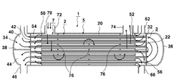
도 1은 본 발명의 바람직한 일례로서 종단면도,
도 2는 도 1의 Ⅱ - Ⅱ선 단면도,
도 3은 도 1의 Ⅲ - Ⅲ선 단면도,
도 4는 도 1의 Ⅳ - Ⅳ선 단면도,
도 5는 본 발명의 사용상태도.1 is a longitudinal sectional view as a preferred example of the present invention;
FIG. 2 is a cross-sectional view taken along the line II-II of FIG. 1;
3 is a cross-sectional view taken along the line III-III of FIG. 1;
4 is a cross-sectional view taken along line IV-IV of FIG.
5 is a use state diagram of the present invention.
이하 첨부된 도면을 참조하여 본 발명의 바람직한 예를 중심으로 보다 구체적으로 상세하게 살펴보기로 한다.Hereinafter, the present invention will be described in more detail with reference to the accompanying drawings.
본 발명의 바람직한 예에 의하면, 도 1 내지 도 5에 예시한 바와 같이 외부의 본체를 이루게 되는 외통(1)의 내측에 외관(20) 및 내관(22)을 갖춘 다수의 2중관(2)을 서로 이격되게 배치하여 구성하되, 외통(1)의 내측으로서 양측엔 상기 2중관(2) 중 내관(22)만이 연통되게 양측 격판(30,32)이 설치되어 제1좌측격실(34)과 제1우측격실(36)을 각각 형성하고 그 중 일측인 제1좌측격실(34)엔 제1수평구획판(38)이 설치되어 상부에 위치한 제1상부격실(40)엔 고온유체 유입구(42)가 마련되고 하부에 위치한 제1하부격실(44)엔 고온유체 배출구(46)가 마련되어 내관유로부(3)를 형성하고; 상기 내관유로부(3)의 제1좌,우측 격실(34,36) 내측으로 인접한 위치엔 상기 2중관(2) 중 외관(20)만이 연통되게 별도의 양측 격판(50,52)이 설치되어 제2좌측격실(54)과 제2우측격실(56)을 각각 형성하고 그 중 일측인 제2우측격실(56)엔 제2수평구획판(58)이 설치되어 상부에 위치한 제2상부격실(60)엔 저온유체 유입구(62)가 마련되고 하부에 위치한 제2하부격실(64)엔 저온유체 배출구(66)가 마련되어 외관유로부(5)가 형성되며; 그리고 상기 외관유로부(5)의 제2좌,우측격실(54,56) 내측으로 인접한 위치엔 상기 2중관(2)의 외측에 위치하게 되는 외측공간(70)만이 서로 연통되게 형성하고 외통(1)의 양측에는 이 외측공간(70)과 연통되는 고온유체 유입구(72)와 고온유체 배출구(74)를 각각 양측 끝부분에 마련하고 이들 고온유체 유입구(72)와 고온유체 배출구(74)의 사이 위치엔 다수의 배플(76)을 상하부에 교번적으로 설치하여 고온유체 유입구(72)로 공급된 고온유체가 외관(20)의 외측으로서 외측공간(70)의 내부를 지그재그로 경유한 다음 고온유체 배출구(74)를 경유 배출될 수 있게 외관외측유로부(7)를 형성하여 그 구성이 이루어지게 된다.According to a preferred embodiment of the present invention, as illustrated in FIGS. 1 to 5, a plurality of
그리하여 이와 같이 구성이 이루어지게 되는 본 발명에 의하면 다음과 같이 그 작동이 이루어지게 된다.Thus, according to the present invention is configured as described above the operation is made as follows.
2중관(2) 중 외관(20)을 중심으로 내,외부에 각각 위치하게 되는 내관(22) 및 외측공간(70)에 있어서, 외관유로부(5), 내관유로부(3) 및 외관외측유로부(7)에 대하여 각각 살펴보기로 한다.In the inner tube (22) and the outer space (70), which are located inside and outside the center (2) of the double pipe (2), respectively, the exterior flow passage portion (5), the inner tube flow passage portion (3) and the exterior exterior portion. Each of the
첫째, 외관유로부(5)의 저온유체 유입구(62)를 거쳐 유입된 저온유체가 제2우측격실(56)에 마련된 제2수평구획판(58)의 상부에 위치한 제2상부격실(60), 상부 외관(20), 제2좌측격실(54)에서 방향전환, 하부 외관(20), 제2우측격실(56)에 마련된 제2수평구획판(58)의 하부에 위치한 제2하부격실(64), 그리고 저온유체 배출구(66)를 거쳐 배출된다.First, the second
둘째, 이와 같이 저온유체가 외관유로부(5)를 경유하여 통과하게 되는 동안, 동시에 외관유로부(5)의 내측에 위치하게 되는 내관(22)에 있어서 내관유로부(3)의 경우엔 고온유체유입구(42)를 거쳐 유입된 고온유체가 제1좌측격실(34)에 마련된 제1수평구획판(38)의 상부에 위치한 제1상부격실(40), 상부 내관(22), 제1우측격실(36)에서 방향전환, 하부 내관(22), 제1좌측격실(34)에 마련된 제1수평구획판(38)의 하부에 위치한 제1하부격실(44), 그리고 고온유체배출구(46)를 경유하여 배출된다.Second, while the low-temperature fluid passes through the
셋째, 위와 같이 저온유체가 외관유로부(5)를 경유하여 통과하고, 동시에 고온유체는 내관유로부(3)를 경유하여 통과하며, 이와 동시에 고온유체는 외관외측유로부(7)에도 통과하게 되는데, 즉 고온유체유입구(72)를 경유하여 유입된 고온유체는 외관(20)의 외측에 위치하게 되는 외측공간(70)을 경유하여 이동하되 다수의 상,하부에 교번적으로 설치된 배플(76)에 의하여 지그재그로 방향전환이 이루어지면서 이동하여 고온유체배출구(74)를 거쳐 외부로 배출된다.Third, as described above, the low-temperature fluid passes through the
그리하여 외관유로부(5)를 통과하게 되는 저온유체는 이 외관유로부(5)의 내,외측에 접하여 직접 열전달이 가능하도록 위치하게 되는 내관유로부(3) 및 외관외측유로부(7)에 의하여 이들 내관유로부(3) 및 외관외부유로부(7)를 동시에 통과하게 되는 고온유체로부터 외관유로부(5)의 저온유체로 이루어지는 열전달에 의한 열교환이 양방향에서 동시에 이루어져 효과적이다.Thus, the low temperature fluid passing through the exterior
따라서, 본 발명에 의하면, 열전달 효율을 높이기 위하여 열교환이 이루어지게 되는 부위의 구성으로서 외관유로부(5)를 중심으로 내, 외측에 위치하게 되는 내관유로부(3) 및 외관외측유로부(7)에서 동시에 열전달이 이루어지도록 하여 동일 공간에서도 전열면적을 넓게 확보하면서 공간의 효과적인 활용과 함께 열전달에 의한 가열효과를 상승시켜 설비비용을 절감하고 경제적으로 활용할 수 있게 되는 장점을 갖게 된다.Therefore, according to the present invention, the inner tube
1: 외통, 2: 2중관,
3: 내관유로부, 5: 외관유로부,
7: 외관외측유로부, 20: 외관,
22: 내관, 30,32,50,52: 격판,
34: 제1좌측격실, 36: 제1우측격실,
38: 제1수평구획판, 40: 제1상부격실,
42: 고온유체유입구, 44: 제1하부격실,
46: 고온유체배출구, 54:제2좌측격실,
56: 제2우측격실, 58: 제2수평구획판,
60: 제2상부격실, 62:저온유체유입구,
64: 제2하부격실, 66: 저온유체배출구,
70: 외측공간, 72: 고온유체유입구,
74: 고온유체배출구, 76: 배플1: outer tube, 2: double tube,
3: inner tube flow part, 5: exterior flow path part,
7: exterior exterior flow path, 20: exterior,
22: inner tube, 30,32,50,52: diaphragm,
34: first left compartment, 36: first right compartment,
38: first horizontal compartment plate, 40: first upper compartment,
42: high temperature fluid inlet, 44: first lower compartment,
46: high temperature fluid outlet, 54: second left compartment,
56: second right compartment, 58: second horizontal compartment,
60: second upper compartment, 62: low temperature fluid inlet,
64: second lower compartment, 66: low temperature fluid outlet,
70: outer space, 72: high temperature fluid inlet,
74: hot fluid outlet, 76: baffle
Claims (1)
외통(1)의 내측으로서 양측엔 상기 2중관(2) 중 내관(22)만이 연통되게 양측 격판(30,32)이 설치되어 제1좌측격실(34)과 제1우측격실(36)을 각각 형성하고 그 중 일측인 제1좌측격실(34)엔 제1수평구획판(38)이 설치되어 상부에 위치한 제1상부격실(40)엔 고온유체 유입구(42)가 마련되고 하부에 위치한 제1하부격실(44)엔 고온유체 배출구(46)가 마련되어 내관유로부(3)를 형성하고;
상기 내관유로부(3)의 제1좌,우측 격실(34,36) 내측으로 인접한 위치엔 상기 2중관(2) 중 외관(20)만이 연통되게 별도의 양측 격판(50,52)이 설치되어 제2좌측격실(54)과 제2우측격실(56)을 각각 형성하고 그 중 일측인 제2우측격실(56)엔 제2수평구획판(58)이 설치되어 상부에 위치한 제2상부격실(60)엔 저온유체 유입구(62)가 마련되고 하부에 위치한 제2하부격실(64)엔 저온유체 배출구(66)가 마련되어 외관유로부(5)가 형성되며; 그리고
상기 외관유로부(5)의 제2좌,우측격실(54,56) 내측으로 인접한 위치엔 상기 2중관(2)의 외측에 위치하게 되는 외측공간(70)만이 서로 연통되게 형성하고 외통(1)의 양측에는 이 외측공간(70)과 연통되는 고온유체 유입구(72)와 고온유체 배출구(74)를 각각 양측 끝부분에 마련하고 이들 고온유체 유입구(72)와 고온유체 배출구(74)의 사이 위치엔 다수의 배플(76)을 상하부에 교번적으로 설치하여 고온유체 유입구(72)로 공급된 고온유체가 외관(20)의 외측으로서 외측공간(70)의 내부를 지그재그로 경유한 다음 고온유체 배출구(74)를 경유 배출될 수 있게 외관외측유로부(7)를 형성하여 그 구성이 이루어지는 것을 특징으로 하는 열교환기.It is configured by arranging a plurality of double pipes 2 having an exterior 20 and an inner tube 22 spaced apart from each other inside the outer cylinder 1 forming the outer body,
As the inner side of the outer cylinder 1, both side diaphragms 30 and 32 are provided on both sides of the double tube 2 so that only the inner tube 22 communicates with each other so that the first left compartment 34 and the first right compartment 36 are respectively located. The first horizontal compartment plate 38 is formed in the first left compartment 34, which is one side thereof, and the high temperature fluid inlet 42 is provided in the first upper compartment 40 positioned at an upper portion thereof. The lower compartment 44 is provided with a hot fluid outlet 46 to form an inner tube flow path 3;
In the adjacent position inside the first left and right compartments (34, 36) of the inner tube flow path (3), separate two side plates (50, 52) are installed so that only the exterior (20) of the double pipe (2) is in communication The second upper compartment 54 is formed to form a second left compartment 54 and a second right compartment 56, and a second horizontal compartment plate 58 is installed on the second right compartment 56, which is one side thereof. A low temperature fluid inlet 62 is provided at 60) and a low temperature fluid outlet 66 is provided at a second lower compartment 64 positioned at a lower portion thereof to form an exterior flow path 5; And
Only the outer space 70 positioned outside the double pipe 2 is formed in communication with each other at a position adjacent to the inside of the second left and right compartments 54 and 56 of the exterior flow passage part 5 and the outer cylinder 1 On both sides of the) is provided a hot fluid inlet 72 and a hot fluid discharge port 74 in communication with the outer space 70 at each end, and between the hot fluid inlet 72 and the hot fluid outlet (74) A plurality of baffles 76 are alternately installed at the upper and lower positions, so that the high temperature fluid supplied to the high temperature fluid inlet 72 passes through the inside of the outer space 70 as a outside of the exterior 20 and then zigzags to the high temperature fluid. Heat exchanger, characterized in that the configuration is made by forming the outer appearance of the outer flow path portion (7) to be discharged via the discharge port (74).
Priority Applications (1)
| Application Number | Priority Date | Filing Date | Title |
|---|---|---|---|
| KR1020110022249A KR20120104698A (en) | 2011-03-14 | 2011-03-14 | Heat exchanger |
Applications Claiming Priority (1)
| Application Number | Priority Date | Filing Date | Title |
|---|---|---|---|
| KR1020110022249A KR20120104698A (en) | 2011-03-14 | 2011-03-14 | Heat exchanger |
Publications (1)
| Publication Number | Publication Date |
|---|---|
| KR20120104698A true KR20120104698A (en) | 2012-09-24 |
Family
ID=47111946
Family Applications (1)
| Application Number | Title | Priority Date | Filing Date |
|---|---|---|---|
| KR1020110022249A KR20120104698A (en) | 2011-03-14 | 2011-03-14 | Heat exchanger |
Country Status (1)
| Country | Link |
|---|---|
| KR (1) | KR20120104698A (en) |
Cited By (5)
| Publication number | Priority date | Publication date | Assignee | Title |
|---|---|---|---|---|
| KR20150059838A (en) * | 2013-11-25 | 2015-06-03 | 최명헌 | Units for Boiler Heat Exchangers and Boiler Fins without it Multi-Tube Heat Exchanger |
| EP2966394A1 (en) * | 2014-07-07 | 2016-01-13 | LG Electronics Inc. | Subcooler and air conditioner including the same |
| WO2016104969A1 (en) * | 2014-12-24 | 2016-06-30 | 최명헌 | Finless-type dual-pipe heat exchange apparatus |
| CN109099734A (en) * | 2018-08-24 | 2018-12-28 | 惠州市溶科环保科技有限公司 | A kind of air curtain heat exchanger |
| WO2022131523A1 (en) * | 2020-12-17 | 2022-06-23 | 삼성전자주식회사 | Heat exchanger and air conditioner having same |
-
2011
- 2011-03-14 KR KR1020110022249A patent/KR20120104698A/en not_active Application Discontinuation
Cited By (7)
| Publication number | Priority date | Publication date | Assignee | Title |
|---|---|---|---|---|
| KR20150059838A (en) * | 2013-11-25 | 2015-06-03 | 최명헌 | Units for Boiler Heat Exchangers and Boiler Fins without it Multi-Tube Heat Exchanger |
| EP2966394A1 (en) * | 2014-07-07 | 2016-01-13 | LG Electronics Inc. | Subcooler and air conditioner including the same |
| US9797658B2 (en) | 2014-07-07 | 2017-10-24 | Lg Electronics Inc. | Subcooler and air conditioner including the same |
| WO2016104969A1 (en) * | 2014-12-24 | 2016-06-30 | 최명헌 | Finless-type dual-pipe heat exchange apparatus |
| KR20160077611A (en) * | 2014-12-24 | 2016-07-04 | 최명헌 | Finsless double pipe heat exchanger |
| CN109099734A (en) * | 2018-08-24 | 2018-12-28 | 惠州市溶科环保科技有限公司 | A kind of air curtain heat exchanger |
| WO2022131523A1 (en) * | 2020-12-17 | 2022-06-23 | 삼성전자주식회사 | Heat exchanger and air conditioner having same |
Similar Documents
| Publication | Publication Date | Title |
|---|---|---|
| US10126014B2 (en) | Heat exchanger for condensing gas boiler | |
| KR20120104698A (en) | Heat exchanger | |
| RU2602947C1 (en) | Condensation heat exchanger with false tubes | |
| CN104315893A (en) | Heat exchanger | |
| CN205262239U (en) | Water -cooled flue gas condenser in two return circuits | |
| KR200414128Y1 (en) | Double tube hot water boiler | |
| JP2016017737A (en) | TED heat exchanger | |
| RU2557146C1 (en) | Radial and spiral heat exchanger | |
| RU2596685C2 (en) | Heat exchange module | |
| CN105466234A (en) | Double-loop water-cooling flue gas condenser | |
| CN105466017A (en) | Multi-way water cooling smoke condenser | |
| KR100986637B1 (en) | Dual lined boiler with miniaturized structure and enhanced heat efficiency | |
| CN202770061U (en) | Shell-and-tube heat exchanger with multiple fluorine paths and tubes distributed in series | |
| CN205300045U (en) | Dry evaporator | |
| CN219474358U (en) | Double-gas-path tube type heat exchanger | |
| CN104896800A (en) | Double reverse heat exchanger | |
| CN104457328A (en) | Heat exchanger | |
| KR101659786B1 (en) | Finsless double pipe heat exchanger | |
| JP2018132256A (en) | Heat exchanger and water heater using the same | |
| KR20180000405A (en) | Heat Exchangeing Apparatus | |
| JP2017096524A (en) | Heat exchanger and water heater | |
| JPS5855332Y2 (en) | Heat exchanger | |
| CN106802018A (en) | Absorption refrigeration unit | |
| KR101672278B1 (en) | Boiler finless type multi-pipe heat exchanger | |
| CN201575743U (en) | Heat exchanger |
Legal Events
| Date | Code | Title | Description |
|---|---|---|---|
| A201 | Request for examination | ||
| E902 | Notification of reason for refusal | ||
| E601 | Decision to refuse application |