KR20120096482A - An insulated mold cavity assembly and method for golf ball manufacturing - Google Patents
An insulated mold cavity assembly and method for golf ball manufacturing Download PDFInfo
- Publication number
- KR20120096482A KR20120096482A KR1020127011585A KR20127011585A KR20120096482A KR 20120096482 A KR20120096482 A KR 20120096482A KR 1020127011585 A KR1020127011585 A KR 1020127011585A KR 20127011585 A KR20127011585 A KR 20127011585A KR 20120096482 A KR20120096482 A KR 20120096482A
- Authority
- KR
- South Korea
- Prior art keywords
- cavity
- layer
- metal
- base
- golf ball
- Prior art date
Links
Images


Classifications
-
- B—PERFORMING OPERATIONS; TRANSPORTING
- B29—WORKING OF PLASTICS; WORKING OF SUBSTANCES IN A PLASTIC STATE IN GENERAL
- B29C—SHAPING OR JOINING OF PLASTICS; SHAPING OF MATERIAL IN A PLASTIC STATE, NOT OTHERWISE PROVIDED FOR; AFTER-TREATMENT OF THE SHAPED PRODUCTS, e.g. REPAIRING
- B29C33/00—Moulds or cores; Details thereof or accessories therefor
- B29C33/38—Moulds or cores; Details thereof or accessories therefor characterised by the material or the manufacturing process
-
- B—PERFORMING OPERATIONS; TRANSPORTING
- B29—WORKING OF PLASTICS; WORKING OF SUBSTANCES IN A PLASTIC STATE IN GENERAL
- B29C—SHAPING OR JOINING OF PLASTICS; SHAPING OF MATERIAL IN A PLASTIC STATE, NOT OTHERWISE PROVIDED FOR; AFTER-TREATMENT OF THE SHAPED PRODUCTS, e.g. REPAIRING
- B29C45/00—Injection moulding, i.e. forcing the required volume of moulding material through a nozzle into a closed mould; Apparatus therefor
- B29C45/0025—Preventing defects on the moulded article, e.g. weld lines, shrinkage marks
-
- B—PERFORMING OPERATIONS; TRANSPORTING
- B23—MACHINE TOOLS; METAL-WORKING NOT OTHERWISE PROVIDED FOR
- B23P—METAL-WORKING NOT OTHERWISE PROVIDED FOR; COMBINED OPERATIONS; UNIVERSAL MACHINE TOOLS
- B23P15/00—Making specific metal objects by operations not covered by a single other subclass or a group in this subclass
- B23P15/24—Making specific metal objects by operations not covered by a single other subclass or a group in this subclass dies
-
- B—PERFORMING OPERATIONS; TRANSPORTING
- B29—WORKING OF PLASTICS; WORKING OF SUBSTANCES IN A PLASTIC STATE IN GENERAL
- B29C—SHAPING OR JOINING OF PLASTICS; SHAPING OF MATERIAL IN A PLASTIC STATE, NOT OTHERWISE PROVIDED FOR; AFTER-TREATMENT OF THE SHAPED PRODUCTS, e.g. REPAIRING
- B29C33/00—Moulds or cores; Details thereof or accessories therefor
- B29C33/76—Cores
-
- B—PERFORMING OPERATIONS; TRANSPORTING
- B29—WORKING OF PLASTICS; WORKING OF SUBSTANCES IN A PLASTIC STATE IN GENERAL
- B29C—SHAPING OR JOINING OF PLASTICS; SHAPING OF MATERIAL IN A PLASTIC STATE, NOT OTHERWISE PROVIDED FOR; AFTER-TREATMENT OF THE SHAPED PRODUCTS, e.g. REPAIRING
- B29C45/00—Injection moulding, i.e. forcing the required volume of moulding material through a nozzle into a closed mould; Apparatus therefor
- B29C45/03—Injection moulding apparatus
- B29C45/04—Injection moulding apparatus using movable moulds or mould halves
-
- B—PERFORMING OPERATIONS; TRANSPORTING
- B29—WORKING OF PLASTICS; WORKING OF SUBSTANCES IN A PLASTIC STATE IN GENERAL
- B29C—SHAPING OR JOINING OF PLASTICS; SHAPING OF MATERIAL IN A PLASTIC STATE, NOT OTHERWISE PROVIDED FOR; AFTER-TREATMENT OF THE SHAPED PRODUCTS, e.g. REPAIRING
- B29C45/00—Injection moulding, i.e. forcing the required volume of moulding material through a nozzle into a closed mould; Apparatus therefor
- B29C45/14—Injection moulding, i.e. forcing the required volume of moulding material through a nozzle into a closed mould; Apparatus therefor incorporating preformed parts or layers, e.g. injection moulding around inserts or for coating articles
- B29C45/14065—Positioning or centering articles in the mould
-
- B—PERFORMING OPERATIONS; TRANSPORTING
- B29—WORKING OF PLASTICS; WORKING OF SUBSTANCES IN A PLASTIC STATE IN GENERAL
- B29C—SHAPING OR JOINING OF PLASTICS; SHAPING OF MATERIAL IN A PLASTIC STATE, NOT OTHERWISE PROVIDED FOR; AFTER-TREATMENT OF THE SHAPED PRODUCTS, e.g. REPAIRING
- B29C45/00—Injection moulding, i.e. forcing the required volume of moulding material through a nozzle into a closed mould; Apparatus therefor
- B29C45/14—Injection moulding, i.e. forcing the required volume of moulding material through a nozzle into a closed mould; Apparatus therefor incorporating preformed parts or layers, e.g. injection moulding around inserts or for coating articles
- B29C45/14819—Injection moulding, i.e. forcing the required volume of moulding material through a nozzle into a closed mould; Apparatus therefor incorporating preformed parts or layers, e.g. injection moulding around inserts or for coating articles the inserts being completely encapsulated
-
- B—PERFORMING OPERATIONS; TRANSPORTING
- B29—WORKING OF PLASTICS; WORKING OF SUBSTANCES IN A PLASTIC STATE IN GENERAL
- B29C—SHAPING OR JOINING OF PLASTICS; SHAPING OF MATERIAL IN A PLASTIC STATE, NOT OTHERWISE PROVIDED FOR; AFTER-TREATMENT OF THE SHAPED PRODUCTS, e.g. REPAIRING
- B29C45/00—Injection moulding, i.e. forcing the required volume of moulding material through a nozzle into a closed mould; Apparatus therefor
- B29C45/17—Component parts, details or accessories; Auxiliary operations
- B29C45/26—Moulds
-
- B—PERFORMING OPERATIONS; TRANSPORTING
- B29—WORKING OF PLASTICS; WORKING OF SUBSTANCES IN A PLASTIC STATE IN GENERAL
- B29K—INDEXING SCHEME ASSOCIATED WITH SUBCLASSES B29B, B29C OR B29D, RELATING TO MOULDING MATERIALS OR TO MATERIALS FOR MOULDS, REINFORCEMENTS, FILLERS OR PREFORMED PARTS, e.g. INSERTS
- B29K2905/00—Use of metals, their alloys or their compounds, as mould material
-
- B—PERFORMING OPERATIONS; TRANSPORTING
- B29—WORKING OF PLASTICS; WORKING OF SUBSTANCES IN A PLASTIC STATE IN GENERAL
- B29L—INDEXING SCHEME ASSOCIATED WITH SUBCLASS B29C, RELATING TO PARTICULAR ARTICLES
- B29L2031/00—Other particular articles
- B29L2031/54—Balls
-
- B—PERFORMING OPERATIONS; TRANSPORTING
- B29—WORKING OF PLASTICS; WORKING OF SUBSTANCES IN A PLASTIC STATE IN GENERAL
- B29L—INDEXING SCHEME ASSOCIATED WITH SUBCLASS B29C, RELATING TO PARTICULAR ARTICLES
- B29L2031/00—Other particular articles
- B29L2031/54—Balls
- B29L2031/546—Golf balls
-
- Y—GENERAL TAGGING OF NEW TECHNOLOGICAL DEVELOPMENTS; GENERAL TAGGING OF CROSS-SECTIONAL TECHNOLOGIES SPANNING OVER SEVERAL SECTIONS OF THE IPC; TECHNICAL SUBJECTS COVERED BY FORMER USPC CROSS-REFERENCE ART COLLECTIONS [XRACs] AND DIGESTS
- Y10—TECHNICAL SUBJECTS COVERED BY FORMER USPC
- Y10T—TECHNICAL SUBJECTS COVERED BY FORMER US CLASSIFICATION
- Y10T29/00—Metal working
- Y10T29/49—Method of mechanical manufacture
- Y10T29/49826—Assembling or joining
- Y10T29/49885—Assembling or joining with coating before or during assembling
Abstract
얇은 층 또는 저-유동 재료의 골프공 커버 또는 덮개 층을 성형하기 위한 단열된 사출 성형 캐비티 조립체는 골프공 층을 형성하기 위한 캐비티-이 골프공 층은 캐비티에 의해 형성되는 공간에 상응하는 두께를 가짐-, 캐비티를 둘러싼 금속 표면층, 및 이 금속 표면층을 둘러싼 단열층을 포함한다. 골프공 층 두께가 감소함에 따라, 금속 표면층 두께는 감소하고 단열층 두께는 증가한다.An insulated injection molding cavity assembly for forming a thin layer or a ball cover or cover layer of low-flow material may comprise a cavity for forming a golf ball layer, the golf ball layer having a thickness corresponding to the space defined by the cavity. Having a metal surface layer surrounding the cavity, and a heat insulating layer surrounding the metal surface layer. As the golf ball layer thickness decreases, the metal surface layer thickness decreases and the insulation layer thickness increases.
Description
본 명세서에 기재되는 실시형태는 일반적으로는 골프공의 제조에 관한 것이며, 구체적으로는 금속 캐비티 몰드 절반부 사이의 단열 재료의 층과 사출 성형된 재료를 사용하여 사출되는 재료의 응결을 늦춤으로써, 재료 응결이 발생하기 전에 얇은 커버 또는 저-유동 재료 커버가 성형되는 것을 가능케 하는 골프공 커버를 골프공에 사출 성형하기 위한 캐비티 몰드 조립체에 관한 것이다.Embodiments described herein relate generally to the manufacture of golf balls, specifically by slowing the condensation of the material injected using the injection molded material and the layer of insulation material between the metal cavity mold halves, A cavity mold assembly for injection molding a golf ball cover into a golf ball that enables a thin cover or low-flow material cover to be molded before material condensation occurs.
골프 산업에서 가장 인기 있는 공의 일부는 0.035 인치 미만의 두께를 갖는 폴리우레탄 커버로, 표준의 사출 성형 캐비티를 사용하여 용이하게 사출 성형하기에는 너무 얇다. 그 결과, Acushnet, Callaway 및 Taylor Made와 같은 회사들은 자신들의 골프공에 얇은 커버를 부착하기 위해 캐스팅 또는 RIM 시스템을 흔히 사용한다. 캐스팅 및 반응 사출 몰드(RIM) 시스템을 고가이고 사출 성형 시스템에 비해 작동이 매우 어렵다. 캐스팅된 또는 RIM 폴리우레탄의 인성을 갖는 사출 성형 TPU 재료들이 현재 입수 가능하다. 예로는 미국특허 제7,540,990호를 참조한다. 하지만, 얇은 폴리우레탄 커버들을 성형할 기술이 없어, 골프공 회사들은 얇은 폴리우레탄 커버를 골프공에 씌우길 원한다면 캐스팅 또는 RIM 공정에 의지해야 한다.Some of the most popular balls in the golf industry are polyurethane covers with thicknesses less than 0.035 inches, which are too thin to be easily injection molded using standard injection molding cavities. As a result, companies like Acushnet, Callaway and Taylor Made often use casting or RIM systems to attach thin covers to their golf balls. Casting and reactive injection mold (RIM) systems are expensive and very difficult to operate compared to injection molding systems. Injection molded TPU materials with toughness of cast or RIM polyurethane are currently available. See, for example, US Pat. No. 7,540,990. However, because there is no technology to form thin polyurethane covers, golf ball companies must rely on casting or RIM processes if they want to cover thin polyurethane covers with golf balls.
전형적으로 골프공 사출 성형 캐비티는 우수한 열 전달체인 금속으로 이루어진다. 금속 몰드에 의한 사출 재료로부터의 열이 제거는 "재료 응결"이 발생하기 전에 용융된 재료가 몰드를 채울 수 없는 정도까지 이르기 때문에, 열가소성 물질 또는 열가소성 엘라스토머와 같은 재료를 사용하여 매우 얇은 커버를 골프공에 사출 성형하는 것은 어렵다. 비교적 두꺼운 커버에서도, 매우 낮은 유동 재료의 사용은 몰드가 완전히 채워지기 전에 "재료가 응결되는" 문제를 갖는다.Golf ball injection molding cavities typically consist of metal, which is a good heat transfer body. Since the removal of heat from the injection material by the metal mold reaches to the extent that the molten material cannot fill the mold before the "material condensation" occurs, a very thin cover may be used using a material such as thermoplastic or thermoplastic elastomer. Injection molding into the ball is difficult. Even with relatively thick covers, the use of very low flow materials has the problem that the material “condenses” before the mold is completely filled.
"재료 응결"이 발생하기 전에 골프공을 위한 얇은 층 또는 저-유동 재료층이 성형되는 것을 가능케 하는 사출 성형 조립체가 본 명세서에 기재된다.Described herein is an injection molding assembly that enables a thin layer or low-flow material layer for a golf ball to be molded before a "material condensation" occurs.
일 양태에 따라, 골프공을 위한 얇은 층 또는 저-유동 재료 커버 또는 덮개 층을 성형하기 위한 사출 성형 캐비티가 제공된다. 사출 성형 캐비티는 골프공 커버 또는 덮개 층을 형성하기 위한 캐비티-골프공 층은 캐비티에 의해 형성되는 공간에 상응하는 두께를 가짐-; 이 캐비티를 둘러싼 금속 표면층; 및 이 금속 표면층을 둘러싼 단열층을 포함한다. 단열층의 두께는 금속층의 두께에 기초하여 선택되며, 금속층의 두께는 요망되는 골프공 층 두께에 의존한다. 더 얇은 골프공 층을 위해, 금속 표면층은 더 얇게 이루어지고, 단열층은 금속층을 통한 열손실을 감소시키도록 더 두껍게 이루어진다.According to one aspect, an injection molding cavity is provided for forming a thin layer or low-flow material cover or cover layer for a golf ball. The injection molded cavity is a cavity for forming a golf ball cover or cover layer, wherein the golf ball layer has a thickness corresponding to the space defined by the cavity; A metal surface layer surrounding the cavity; And a heat insulating layer surrounding the metal surface layer. The thickness of the thermal insulation layer is selected based on the thickness of the metal layer, and the thickness of the metal layer depends on the desired golf ball layer thickness. For thinner golf ball layers, the metal surface layer is made thinner, and the thermal insulation layer is made thicker to reduce heat loss through the metal layer.
다른 양태에 따라, 골프공을 위한 얇은 층 또는 저-유동 재료층을 성형하기 위한 사출 성형 캐비티는 골프공 층의 외면을 형성하기 위한 캐비티, 이 캐비티를 둘러싼 미리 정해진 두께의 금속면; 및 금속면을 적어도 부분적으로 둘러싼 단열층을 포함한다. 단열층은 금속면에 대해 일정한 영역에 배치된 복수의 영역을 포함한다.According to another aspect, an injection molding cavity for forming a thin layer or low-flow material layer for a golf ball includes a cavity for forming an outer surface of a golf ball layer, a metal surface of a predetermined thickness surrounding the cavity; And an insulating layer at least partially surrounding the metal surface. The heat insulation layer includes a plurality of regions disposed in a constant region with respect to the metal surface.
또 다른 양태에 따라, 얇은 층 또는 저-유동 재료층을 골프공 코어에 성형하기 위한 사출 성형 캐비티 조립체는 골프공 층을 형성하기 위한 캐비티-골프공 층은 상기 캐비티에 의해 형성되는 공간에 상응하는 두께를 가짐-; 이 캐비티를 둘러싼 미리 정해진 두께의 단열층; 및 이 단열층을 둘러싼 금속 캐비티 몰드 조립체를 포함한다. 단열층은 금속 캐비티 조립체의 열전도율보다 작은 열전도율을 갖는다.According to yet another aspect, an injection molded cavity assembly for forming a thin layer or low-flow material layer into a golf ball core comprises a cavity-golf ball layer for forming a golf ball layer corresponding to the space defined by the cavity. Having a thickness; A heat insulation layer of a predetermined thickness surrounding the cavity; And a metal cavity mold assembly surrounding the heat insulating layer. The thermal insulation layer has a thermal conductivity less than that of the metal cavity assembly.
다른 양태에 따라, 커버 또는 덮개 층을 골프공에 형성하기 위한 사출 성형 캐비티 조립체는 제1 및 제2 대향 몰드 절반부를 포함한다. 각각의 대향 몰드 절반부는 완전한 캐비티를 형성하도록 대향 몰드 절반부를 향한 일면에 부분 또는 절반 캐비티를 갖고, 완전한 캐비티는 매달린 골프공 코어를 캐비티 안에 수용하고 포위하도록 구성됨으로써, 골프공 코어와 몰드 절반부들 사이에 몰드 캐비티가 형성된다. 각각의 몰드 절반부는 골프공 커버 또는 덮개 층의 외면을 형성하기 위한 사출 성형면의 절반부를 형성하도록 구성된 몰드 캐비티를 향한 외면을 갖는 몰드 절반 캐비티에 고정된 금속 표면층과, 캐비티의 적어도 일부 둘레에서 금속 표면층과 몰드 절반부 사이로 연장된 단열층을 포함한다.According to another aspect, an injection molded cavity assembly for forming a cover or cover layer on a golf ball includes first and second opposing mold halves. Each opposing mold half has a portion or half cavity on one side facing the opposing mold half to form a complete cavity, wherein the complete cavity is configured to receive and enclose a suspended golf ball core in the cavity, thereby between the golf ball core and the mold halves. In the mold cavity is formed. Each mold half has a metal surface layer secured to the mold half cavity having an outer surface facing the mold cavity configured to form a half of the injection molded surface for forming the outer surface of the golf ball cover or cover layer, and the metal around at least a portion of the cavity. An insulating layer extending between the surface layer and the mold half.
골프공 코어는 고무, 플라스틱 등의 하나의 재료로 된 대체로 구형의 일체형 본체이거나, 하나 이상의 덮개 층 또는 다중 부분의 고무 또는 플라스틱 코어와 같은 다층을 자체적으로 가질 수 있다. 코어는 미리 정해진 영역에서 구체가 아닐 수 있다. 사출 성형 캐비티 조립체는 형성되는 골프공 층의 요망되는 형태에 따라 구형 캐비티 또는 비구형 캐비티를 형성하도록 설계될 수 있다. 일 실시형태에서, 각각의 절반 캐비티는 반구형 또는 실질적으로 반구형 형태이며, 골프공의 층은 균일한 두께이도록 의도된다. 다른 실시형태에서, 예컨대 덮개 층을 형성하기 위한 제1 조립체와 덮개 층 위의 외측 커버를 형성하기 위한 제2 조립체인, 상이한 단열된 캐비티 조립체들이 다층 공들을 형성하도록 제공될 수 있다. 일 실시형태에서, 하나의 캐비티 조립체의 절반 캐비티들은 완전한 구체는 아니고 일부 영역이 더 얇고 다른 영역이 더 두꺼운 덮개 층(또는 커버 층)을 형성하기 위한 비구형 캐비티를 형성하도록 설계될 수 있다.The golf ball core may be a generally spherical monolithic body of one material, such as rubber, plastic, or the like, or may itself have multiple layers such as one or more cover layers or multiple parts of rubber or plastic core. The core may not be a sphere in a predetermined region. The injection molded cavity assembly may be designed to form a spherical cavity or a non-spherical cavity depending on the desired shape of the golf ball layer to be formed. In one embodiment, each half cavity is hemispherical or substantially hemispherical in shape and the layer of golf balls is intended to be of uniform thickness. In another embodiment, different insulated cavity assemblies, for example a first assembly for forming a cover layer and a second assembly for forming an outer cover over the cover layer, may be provided to form multilayer balls. In one embodiment, the half cavities of one cavity assembly are not perfect spheres and may be designed to form a non-spherical cavity for forming a cover layer (or cover layer) in which some areas are thinner and other areas are thicker.
여러 가지 특징, 양태 및 실시형태가 "구체적인 내용" 항목에서 후술된다.Various features, aspects, and embodiments are described below in the "Specific Content" section.
특징, 양태 및 실시형태가 첨부 도면과 연계하여 기재된다.
도 1은 종래의 골프공 사출 몰드 캐비티 조립체를 보여주는 단면도이다.
도 2는 일 실시형태에 따른 골프공 사출 몰드 캐비티를 구성하는 방법의 예를 보여주는 순서도이다.
도 3 내지 9는 다양한 실시형태에 따라 구성된 골프공 사출 몰드 캐비티 조립체의 예를 보여주는 단면도이다.
도 10은 단열된 사출 몰드 캐비티 조립체의 다른 실시형태의 하나의 몰드 절반부에 사용되는 금속 성형면 또는 절반 셸의 측면 사시도이다.
도 11은 도 10에 도시된 금속 성형층의 저면을 보여주는 저부 사시도이다.
도 12는 딤플을 성형층의 외면 또는 밑면에 절삭한 후 딤플 패턴을 성형층의 사출 성형면 또는 내면에 절삭하기 전의, 도 10 및 11의 금속 성형층 또는 절반 셸을 형성하는데 사용되는 금속부를 통한 수직 단면도이다.
도 13은 도 10 내지 12의 절반 셸을 수용하기 위한 몰드 절반부의 베이스의 상부 사시도이다.
도 14는 도 13의 몰드 베이스를 통한 단면도이다.
도 15는 도 14와 유사하지만, 도 10 내지 12의 금속 절반 셸 성형층이 베이스 내의 적소로 하강된 상태를 보여주는 단면도이다.
도 16은 반구형 셸부가 베이스 내의 반구형 캐비티 내에 맞물린, 위치 설정된 금속 절반 셸을 보여주는 단면도이다.
도 17a 내지 17d는 사출 몰드 조립체의 하나의 몰드 절반부 내의 코어 핀과 벤트 핀, 그리고 코어 핀 및 벤트 핀 수용 보어를 위한 다른 구성을 보여주는 단면도이다.
도 18은 도 10 내지 15의 부분들로부터 조립되어 골프공 커버 층 성형용 사출 몰드 캐비티 조립체의 한 쪽 절반부를 형성하는 몰드 절반부의 일 실시형태를 보여주는 단면도이다.Features, aspects, and embodiments are described in conjunction with the accompanying drawings.
1 is a cross-sectional view showing a conventional golf ball injection mold cavity assembly.
2 is a flow chart showing an example of a method of constructing a golf ball injection mold cavity according to one embodiment.
3-9 are cross-sectional views illustrating examples of golf ball injection mold cavity assemblies constructed in accordance with various embodiments.
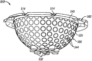
10 is a side perspective view of a metal forming surface or half shell used in one mold half of another embodiment of the insulated injection mold cavity assembly.
FIG. 11 is a bottom perspective view illustrating a bottom of the metal forming layer illustrated in FIG. 10.
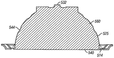
12 is through the metal portion used to form the metal shaping layer or half shell of FIGS. 10 and 11 before cutting the dimple to the outer or bottom surface of the shaping layer and before cutting the dimple pattern to the injection molding surface or inner surface of the shaping layer. Vertical section.
13 is a top perspective view of the base of the mold half for receiving the half shells of FIGS. 10-12.
14 is a cross-sectional view through the mold base of FIG. 13.
FIG. 15 is a cross-sectional view similar to FIG. 14 but showing a state in which the metal half shell forming layers of FIGS. 10 to 12 are lowered in place in the base.
16 is a cross-sectional view showing the positioned metal half shell with the hemispherical shell portion engaged in a hemispherical cavity in the base.
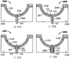
17A-17D are cross-sectional views showing another configuration for core pins and vent pins, and core pins and vent pin receiving bores in one mold half of the injection mold assembly.
18 is a cross-sectional view showing one embodiment of a mold half assembled from the portions of FIGS. 10-15 to form one half of the injection mold cavity assembly for forming a golf ball cover layer.
본 명세서에서 검토되는 일정한 실시형태는 골프공 코어에 층을 형성하기 위한 단열된 몰드 캐비티 조립체를 제공한다. 층은 골프공의 내층 또는 덮개 층이거나 커버 층 또는 외층일 수 있다.Certain embodiments discussed herein provide an insulated mold cavity assembly for layering a golf ball core. The layer may be an inner layer or cover layer of the golf ball or a cover layer or outer layer.
본 설명을 읽은 해당 분야의 통상의 지식을 가진 자(당업자)는 본 발명을 다양한 다른 실시형태 및 다른 용례로 어떻게 구현할지 명확히 알게 될 것이다. 하지만, 비록 본 발명의 다양한 실시형태가 본 명세서에 기재되지만, 이러한 실시형태는 한정이 아닌 예시로서만 제출된 것임을 이해한다. 그와 같이, 다양한 다른 실시형태의 상세한 설명은 본 발명의 범위나 폭을 한정하도록 구성되지 않는다.Those skilled in the art, having read this description, will clearly know how to implement the invention in various other embodiments and other applications. However, although various embodiments of the invention are described herein, it is to be understood that such embodiments are submitted by way of illustration and not of limitation. As such, detailed descriptions of various other embodiments are not intended to limit the scope or breadth of the present invention.
본 명세서에 사용되는, "코어"라는 용어는 고무, 플라스틱 등의 단품 또는 일체형 코어, 다중 부분 코어, 또는 하나 이상의 덮개 층들이 이미 형성된 중심부 또는 중간부를 포함하는 코어와 같이, 하나 이상의 추가의 층들이 형성되어 적층될 임의의 부분적으로 형성된 골프공을 나타낸다. "층"이라는 용어는 골프공의 중심과 골프공의 최외면 사이의 임의의 층, 즉, 외측 커버 층 또는 임의의 중간 덮개, 또는 중심과 외면 사이의 내층 등을 의미한다. "구형" 또는 "반구형"이란 용어는 완전히 또는 실질적으로 구형 또는 반구형인 면 또는 층을 나타내며, 골프공에서 일반적으로 발견되는 딤플, 관형 격자 형상, 역상의 딤플 등의 표면 패턴을 갖는 구형 층을 포함한다.As used herein, the term "core" refers to one or more additional layers, such as a single or integral core, such as rubber, plastic, multi-part cores, or a core that includes a central or intermediate portion in which one or more cover layers have already been formed. Represents any partially formed golf ball that is to be formed and stacked. The term "layer" means any layer between the center of the golf ball and the outermost surface of the golf ball, that is, an outer cover layer or any intermediate cover, or an inner layer between the center and the outer surface and the like. The term “spherical” or “semi-spherical” refers to a face or layer that is completely or substantially spherical or hemispherical, including spherical layers having surface patterns such as dimples, tubular lattice shapes, inverted dimples, and the like commonly found in golf balls. do.
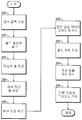
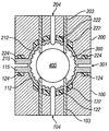
도 1은 각기 반구형 오목부를 갖는 대향면을 갖는 상부 몰드 절반부(200)와 하부 몰드 절반부(100)를 구비한 종래의 골프공 사출 몰드 조립체를 보여주는 도면이다. 이들 오목부는 함께 몰드 캐비티(300)를 형성하며, 몰드 캐비티(300) 내에 골프공 코어(400)가 매달려서, 커버 또는 덮개 층이 공과 상부 및 하부 몰드 절반부 사이의 공동의 잔여부에 성형될 수 있다. 골프 공 커버 층의 외면을 형성하기 위한 반구형 사출 성형 금속면(101, 201)은 원하는 딤플 패턴을 형성하도록 형상화되어 있다. 도시된 바와 같이, 반구형 캐비티는 원하는 골프공 딤플 패턴을 형성하도록 돌기 또는 융기부를 갖는다. 골프공 코어(400)는 각각 상부 및 하부의 핀(203, 103)을 통해 캐비티(300)의 중심에 매달린다. 상부 및 하부 벤트 핀(204, 104)이 각각 포함되어, 캐비티(300)의 가스가 성형 중에 배출될 수 있다. 몰드 절반부의 대향면 내의 오목부에 의해 형성된 하나 이상의 재료 사출구 또는 게이트(301)에 의해, 커버 재료가 코어(400)와 성형면(101, 201) 사이의 간격으로 사출될 수 있다.1 shows a conventional golf ball injection mold assembly having an
재료가 캐비티(300) 안으로 사출됨에 따라, 캐비티 온도는 재료 사출이 시작되는 때에 사출되는 재료의 응결점보다 낮은 것이 보통이다. 사출되는 재료는 공동(300)의 중심에 매달린 구형 코어(400) 또는 덮인 코어와 사출 성형 캐비티의 금속 벽(101, 201) 사이로 사출되는 것이 보통이다. 열은 금속 캐비티 벽(101)과 매달린 코어(400) 양쪽에 의해 재료로부터 인출된다. 매달린 코어의 외측이 고무 또는 플라스틱과 같은 다소 낮은 열전도 재료인 것이 보통이므로, 사출되는 재료로부터 코어(400)로의 열 제거 속도는 금속 사출 성형 캐비티의 면(101, 201)으로의 열 제거 속도만큼 빠르지 않은 것이 보통이다.As the material is injected into
매우 얇은 층을 성형할 때 또는 매우 낮은 유동 재료를 성형할 때, 사출되는 재료로부터 열 제거의 속도는 재료가 금속 벽(101, 201)과 매달린 코어(400) 사이의 전체 캐비티 공간(300)을 채울 기회를 갖기 전에 응고될 만큼 충분히 빠를 수 있다. 이렇게 되면, 커버 또는 덮개 층은 골프공 코어(400)를 충분히 싸지 않아, 결과로서 얻는 부분이 결함이 있다고 고려된다.When forming a very thin layer or when forming a very low flow material, the rate of heat removal from the injected material is such that the material fills the
조속한 재료의 냉각이란 문제를 해결하기 위한 종래의 시도는 플라스틱을 더 신속히 캐비티 안에 사출하는 것을 포함한다. 하지만 이것은 일정한 층 두께까지만 작용하고, 그 아래에서 얇은 사출된 층은 너무 얇아서, 사출 성형기의 재료 사출 속도 또는 압력 한계를 초과하는 지점까지 플라스틱의 사출 속도가 증가해야 한다. 또는, 사출 성형기의 재료 사출 속도를 초과하지 않는 다른 경우, 코어(400) 상의 힘이 코어(400)가 공정 중에 변형되거나, 코어(400)가 공정 중에 중심에서 벗어나게 되는 정도의 사출 속도 및/또는 사출 압력이 요구된다. 코어(400)가 변형되거나 중심에서 벗어나는 경우, 결과로서 얻는 제품은 결합이 있다고 고려된다.Conventional attempts to solve the problem of rapid cooling of the material include injecting the plastic into the cavity more quickly. However, this only works up to a certain layer thickness, and the thin injected layer below it is so thin that the injection speed of the plastic has to increase to a point that exceeds the material injection speed or pressure limit of the injection molding machine. Or, in other cases where the injection speed of the injection molding machine does not exceed the material injection speed, the injection speed and / or the force such that the force on the
대조적으로, 여기에 기재되는 실시형태는 사출되는 재료의 응결 속도를 늦춤으로써 "재료 응결 발생" 전에 얇은 층 또는 저 유동 재료가 골프공 코어 둘레에 성형될 수 있도록, 캐비티와 사출 성형된 재료를 둘러싼 금속 몰드 절반부들 사이에 단열 재료의 층을 사용한다.In contrast, the embodiments described herein surround the cavity and the injection molded material such that a thin layer or low flow material can be molded around the golf ball core prior to "material condensation" by slowing the congealing rate of the material being injected. A layer of insulating material is used between the metal mold halves.
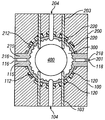
도 3의 실시형태에서, 도 1의 몰드 절반부(100, 200)의 몰드면(101, 201)은 단열 재료의 성형면 또는 층(205, 206)으로 대체된다. 더 상세히 후술되는 도 4의 다른 실시형태에서, 도 1의 금속 성형면(101, 201)은 캐비티(300) 내의 몰드면을 각각 형성하는 비교적 얇은 절반 셸 또는 금속 성형층(112, 212)과, 개별적인 금속층(112, 212)과 각각의 금속 몰드 절반부 사이의 단열 재료의 층(102, 202)으로 각각 대체된다.In the embodiment of FIG. 3, the mold surfaces 101, 201 of the mold halves 100, 200 of FIG. 1 are replaced with molded surfaces or
도 1의 종래 기술 사출 성형 조립체에서, 플라스틱 재료가 매달린 골프공 코어(400)가 수용된 공동(300) 안으로 사출됨에 따라, 골프공 커버 또는 덮개 층을 사출 성형할 때, 유동 플라스틱은 금속 성형면(101, 201) 및 코어(400)와 접촉하게 된다. 금속면(101)은 플라스틱 재료에 의해 가열된다. 도 3의 실시형태에서와 같이 단열 재료(205, 206)를, 또는 도 4의 실시형태에서와 같이 개별적인 금속 성형면 층(112, 212) 아래의 단열 재료(102, 202)를 성형면으로서 가짐으로써, 용융된 플라스틱으로부터 성형면을 통한 열 제거가 늦추어지고 용융된 플라스틱의 온도는 예컨대 금속 성형면 아래에 아무런 단열 재료도 없는 경우보다 더 긴 시간 동안 녹는점 위에 머무른다.In the prior art injection molding assembly of FIG. 1, when injection molding a golf ball cover or cover layer, as the plastic material suspended
어떠한 용융된 플라스틱도 응고되지 않도록 완전히 방지할 만큼 단열층, 예컨대, 층(205, 206) 또는 층(102, 202)이 두껍고 금속층 예컨대 층(112, 212)이 얇을 필요는 없다. 하지만, 도 3의 단열층(205, 206)의 재료 및 치수와 도 4의 단열층(102, 202)과 금속층(112, 212)의 결합된 치수는 용융된 플라스틱 재료가 코어(400)와 둘레의 성형면 사이의 캐비티 공간(300)을 충분히 채우는 것을 가능케 해야 한다. 일반적으로, 몰드 캐비티의 각각의 측면의 2 개의 층(102, 112; 202, 212)의 두께는 요망되는 커버 층 두께 또는 부피에 의존한다. 비교적 얇은 커버 층을 위해, 금속 성형면 층(112, 212)은 열을 더 적게 흡수하도록 얇게 이루어지고, 단열층, 예컨대, 층(102, 202)은 재료 응결이 더 중요한 더 얇은 커버 층을 사출 성형할 때 단열이 더욱 요망되므로 두껍게 이루어진다. 따라서 몰드 절반 캐비티의 외면을 형성하는 금속면 층의 두께가 감소함에 따라 단열층의 두께는 증가하는 것이 일반적이다.The thermal insulation layer, such as
따라서 얇은 층의 성형을 아래의 실시형태에서 기재되는 것과 같이 가능케 하도록 사출 몰드 캐비티 내에 단열된 재료층을 사용하는 것은 골프공의 얇은 커버 및 덮개 층의 성형, 저 유동 재료 골프공 층의 성형, 또는 양쪽을 가능케 하는 새로운 접근법이다.Thus, using an insulated material layer in an injection mold cavity to enable molding of a thin layer, as described in the embodiments below, may be achieved by forming a thin cover and lid layer of a golf ball, forming a low flow material golf ball layer, or It's a new approach that makes both possible.
단열층은 금속 성형면이나 금속 캐비티 조립체의 열전도율보다 작은 열전도율을 갖는 모든 재료일 수 있다. 금속 성형면 또는 금속 캐비티 조립체에 비해 단열층으로 작용하는 한, 금속, 플라스틱, 세라믹, 유리, 액체 또는 가스 재료, 또는 그 밖의 모든 형태의 재료 또는 재료들의 조합일 수 있다.The thermal insulation layer may be any material having a thermal conductivity less than that of the metal forming surface or the metal cavity assembly. It can be a metal, plastic, ceramic, glass, liquid or gaseous material, or any other type of material or combination of materials, so long as it acts as an insulating layer relative to the metal forming surface or the metal cavity assembly.
도 2는 골프공의 얇은 커버 층을 형성하도록 사용될 수 있거나 재료를 저 용융 유동 특성으로 사출 성형하도록 사용될 수 있는, 단열된 사출 성형 캐비티를 구성하는 공정의 예를 보여주는 순서도이다. 비록 아래의 설명이 골프공의 외측 커버 층의 성형에 관한 것이지만, 골프공 코어에 덮개 층을 성형하는 데에도 동일한 공정이 사용될 수 있다. 먼저, 단계(220)에서, 몰드 캐비티의 각각의 절반부를 위해, 금속의 블록을 캐비티 조립체의 벌크의 대략적인 치수로 가공한다. 단계(222)에서, 각각의 블록을 요망되는 몰드 절반 형태로 절삭한다. 여기서, 다른 몰드 절반부와 대향된 블록의 면이 요망되는 반구형 오목부(114, 214)를 형성하도록 절삭되고, 오목부가 층(102, 112, 또는 202, 212)의 선택된 결합된 두께와 동일한 양으로 요망되는 커버 층 두께보다 크도록 치수가 선택된다. 이어, 단계(224)에서, 벤트 핀(104, 204)을 수용하기 위해 몰드 절반부에 파일럿 홀을 천공할 수 있다. 각각의 몰드 절분부의 이 홀(구멍)들은 에폭시 수지와 같은 폴리머 단열 재료의 경우에 과잉의 단열 재료가 탈출하는 지점일 수 있다. 파일럿 홀은 캐비티의 중심 내에 골프공 코어(400)를 지지하는 코어 핀(103, 203)을 수용하기 위해서도 천공된다. 코어(400)는 단일 부분 코어 또는 다중 부품 고무 또는 플라스틱 코어이거나, 중심 코어 및 하나 이상의 덮개 층과 같은 여러 층으로 구성될 수 있다.2 is a flow chart showing an example of a process for constructing an insulated injection molding cavity, which may be used to form a thin cover layer of a golf ball or may be used to injection mold material with low melt flow characteristics. Although the description below relates to the shaping of the outer cover layer of a golf ball, the same process can be used to form the cover layer on the golf ball core. First, in
단계(226)에서, 주변 림을 갖는 반구 형태의 각각의 몰드 절반부의 내측 또는 대향면을 위해 금속 절반 셸 또는 층이 형성된다. 일 실시형태에서 금속층은 대략 0.03 내지 0.3 인치의 두께이며, 림이 각각의 몰드 절반부 내의 캐비티의 림 위로 연장되도록 캐비티(114, 214)에 끼워져 단열 재료를 위한 적절한 공간이 몰드 절반부와 금속 층 또는 절반 셸 사이에 형성될 수 있게 하는 외경을 갖는다. 다른 실시형태에서, 금속 절반 셸 또는 층의 두께는 도 10 내지 18과 연계하여 후술되는 것과 같이 0.03 인치 미만일 수 있다. 층이 완전히 구형이 아닌, 즉, 일부 영역이 더 두껍고 다른 영역이 더 얇게 형성되는 일부 실시형태에서 형태는 반구형이 아닐 수 있다. 금속 셸은 단계(230)와 연계하여 후술되는 몰드 공동 내에 셸을 접착하는 공정 중의 힘에 더 잘 견디도록 림 둘레 등의 일부 영역이 더 두껍게 이루어지거나, 구체적으로는 금속층이 매우 얇은 경우 변형되지 않도록 접착 공정 중에 그 외면이 지지될 수 있다.In
단계(228)에서, 단열 재료는 2 개의 몰드 절반부의 오목한 면의 반구형 캐비티와 외측 림 위로 연장되도록 추가될 수 있다. 예컨대, 2 개 부분 에폭시와 같은 액체 프리-폴리머 플라스틱 재료가 충분한 양으로 각각의 몰드 절반면에 코팅될 수 있다.In
단계(230)에서, 절반 셸 또는 금속층(112, 114)은 반구부가 금속층과 몰드 절반부의 대향면 사이에 간격을 두고, 각각의 몰드 면 내의 반구형 캐비티와의 적소에 일치될 때까지 각각의 몰드 절반면에 압박된다. 단계(232)에서, 폴리머 재료를 적소에서 경화시킬 수 있고, 과잉의 폴리머 재료는 트리밍될 수 있다. 따라서, 일부 실시형태에서, 단열 재료는 절반 셸을 캐비티 조립체에 영구적으로 결합시키는 접착제로서 작용한다. 다른 실시형태에서, 절반 셸을 캐비티 조립체에 영구적으로 결합시키도록 접착제가 추가될 수 있다. 단열층의 두께는 0.25 인치 이하일 수 있고, 일 실시형태에서, 단열층은 0.002 내지 0.08 인치 범위의 두께를 갖는다.In
후술되는 것과 같이, 단열 재료는 캐비티에 대해 특정한 영역에 위치된 복수의 영역을 가질 수 있다. 그러한 실시형태에서, 단열 재료를 패터닝하거나 제거하는 추가의 단계 또한 수행될 것이다.As described below, the thermal insulation material may have a plurality of regions located in specific regions with respect to the cavity. In such embodiments, additional steps of patterning or removing the insulating material will also be performed.
추가적으로, 많은 실시형태에서, 절반 셸과 캐비티 조립체 사이에는, 절반 셸이 조립체 내의 정확한 깊이와 위치에 배치되는 것을 확보하도록 작용하는 접촉점이 있다.In addition, in many embodiments, there is a contact point between the half shell and the cavity assembly that serves to ensure that the half shell is positioned at the correct depth and position within the assembly.
단계(234)에서, 골프공 딤플 패턴의 역상을 금속 절반 셸 또는 층의 외면, 즉, 몰드 표면에 절삭하도록 예컨대 5축 CNC 머시닝 장치를 사용한다.In
단계(236)에서, 벤트 핀, 게이트, 코어 핀 등을 비롯한 조립체의 다른 구성요소들을 캐비티 조립체 안에 가공할 수 있다.In
일정한 실시형태에서, 절반 셸이 캐비티 조립체에 삽입되기 전에, 절반 셸 또는 금속층에는 역 딤플 패턴도 역시 형성될 수 있다.In certain embodiments, an inverted dimple pattern may also be formed in the half shell or metal layer before the half shell is inserted into the cavity assembly.
도 3 내지 18은 다양한 실시형태에 따라 구성된 골프공 사출 성형된 캐비티의 예를 보여주는 도면이다. 알 수 있는 것과 같이, 도 3의 실시형태에서, 금속 몰드면(101, 201)은 단열 재료층(205, 206)으로 대체되었다. 이와 달리, 도 4의 실시형태에서 설명된 것과 같이, 단열층(102, 202)이 금속 절반 셸 또는 층(112, 212) 바로 아래, 즉, 금속 몰드 절반부(100, 200)의 표면과 금속 절반 셸 또는 층(112, 212) 사이에 각각 위치한다. 비록 단열층(102, 202)이 도 4에서 각각의 반구형 캐비티의 가장자리로부터 중심으로 두께가 증가하지만, 다른 실시형태에서는 균일한 두께를 가질 수 있다.3-18 show examples of golf ball injection molded cavities constructed in accordance with various embodiments. As can be seen, in the embodiment of FIG. 3, the metal mold faces 101, 201 have been replaced with insulating material layers 205, 206. Alternatively, as described in the embodiment of FIG. 4, the thermal insulation layers 102, 202 are directly under the metal half shell or layers 112, 212, ie, the surface and metal half of the
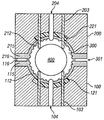
도 4의 실시형태에서, 금속 표면층 또는 셸(112, 212)은 각각의 몰드 절반부의 림을 덮도록 외측으로 연장된 반구부를 둘러싼 외측 림(115, 215)을 각각 갖고, 반구형 캐비티로부터 각각의 셸 또는 층의 외측 가장자리로 연장된 사출 게이트 영역을 형성하여 사출구 또는 게이트(301)를 형성하는 대향된 반구형 홈 또는 오목부(116, 216)로 형성되며, 각각의 단열층(102, 202)은 사출구(301)에서 사출 게이트 영역의 적어도 일부 아래에서 연장된 일부(118, 218)를 갖는다. 각각의 절반 셸 또는 금속층(112, 212)의 림은 단열층의 연장부(118, 218)를 수용하도록 언더커팅될 수 있다. 도 5의 실시형태에서, 하지만, 단열층(102, 202)은 각각의 절반 셸(112, 212)의 림에서 사출 게이트 영역 아래에서 연장되지 않는다. 도 5의 실시형태는 그 외에는 도 4의 것과 동일하며, 적절한 유사한 부분을 위해 유사한 참조 번호가 사용된다.In the embodiment of FIG. 4, the metal surface layer or
캐비티(300) 전체를 단열할 필요는 없다. 예컨대 단열된 영역은 최후에 플라스틱으로 채워지는 영역인 몰드의 하부 절반부(100) 내의 부분만이거나, 몰드의 상부 절반부(200) 내의 부분만이거나, 사출 게이트가 플라스틱 재료를 공동 안으로 도입하는 균분원 영역 둘레의 영역 내일 수 있다.It is not necessary to insulate the
예컨대, 도 6의 실시형태에서, 금속 몰드 절반부 내에 공동과 하부 오목부를 형성하는 각각의 금속층(112, 212) 사이의 단열층은 분리되어, 금속 성형면 또는 절반 셸(112, 212) 바로 아랫니지만 사출 게이트 영역의 아래가 아닌 일부 장소에 존재하는 단열 재료의 영역(120, 220)으로 구성된다. 이 구성에서, 몰드 절반부(100, 200)는 단열 재료가 성형면과 접촉하는 영역 내의 돌출부(도시 생략)를 포함할 수 있으며, 돌출부는 성형면을 위한 일치 및/또는 정렬 지점으로 작용할 수 있다.For example, in the embodiment of FIG. 6, the thermal insulation layer between each of the metal layers 112, 212 forming the cavity and the lower recesses in the metal mold half is separated so that it is just below the metal forming surface or the
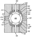
도 7의 실시형태에서, 단열 재료의 연속 호형 영역(121, 221)이 금속층(112, 212)과 몰드 절반부의 하부면 사이의 캐비티(300)의 각각의 절반부의 극지 영역에 제공된다. 이것은 극지 영역을 더 긴 시간 동안 따뜻하게 유지함으로써 "잔주름"과 같은 냉각 용접점 및 성형 결함이 벤트 핀 부근에 생기는 것을 방지하는데 도움이 된다.In the embodiment of FIG. 7,
도 8의 실시형태에서, 전술한 예에서와 같이, 단열 재료의 개별적인 영역(122, 222)이 캐비티(300)의 각각의 절반부의 극지 영역에 제공되지만, 단열 영역은 서로 다른 영역에 한정된다. 본 실시형태에서, 각각의 코어 및 벤트 핀(103, 203, 104, 204) 바로 주변의 단열체는 핀들이 금속으로 포위되고 단열 영역(122, 222)이 코어 및 벤트 핀으로부터 이격되도록 제거되었다. 축적된 휘발성 고상물을 핀으로부터 제거하기 위해 종종 캐비티 안에 용매를 주입하기 때문에, 이것은 사용되는 단열체의 형태에 따라 중요할 수 있다. 용매가 예컨대 플라스틱인 단열 재료와 접촉한다면, 단열 재료는 팽창, 부식, 또는 붕괴될 수 있다. 핀을 둘러싼 금속은 이러한 상호 작용을 방지한다.In the embodiment of FIG. 8, as in the example described above,
도 9의 실시형태에서, 핀으로부터 이격된 단열 재료의 영역 또는 일부(122, 222)는 도 8에서와 같이 캐비티(300)의 각각의 절반부의 극지 영역에 제공되며, 추가의 단열 영역(124, 224)도 역시 사출 게이트 영역(301) 내의 각각의 절반 셸 또는 금속층(112, 212)의 림(115, 215) 아래에 제공된다. 전술한 예에서와 같이, 각각의 코어 및 벤트 핀(103, 203, 104, 204) 둘레의 단열체는 핀이 금속으로 포위되도록 제거되었다. 단열 재료를 사출 게이트 부근에 두는 것은 이 영역에서의 폴리머 열손실의 방지에 도움이 되는 동시에 인접한 단열되지 않은 게이트와 극지 영역이 매우 신속하게 응고될 수 있게 하여 과잉의 폴리머 증발을 방지할 것이다.In the embodiment of FIG. 9, regions or
도 10 내지 18은 사출 몰드 캐비티 조립체의 다른 실시형태의 한 쪽 몰드 캐비티 절반부는 물론 이 몰드 캐비티 절반부의 구성의 여러 단계를 더 상세히 도시한다. 본 실시형태의 몰드 캐비티는 도 4의 것과 유사하며, 금속 몰드 캐비티 베이스(510), 베이스의 오목한 표면에 고정된 금속 딤플 층(512), 그리고 금속층(512)과 베이스(510) 사이에 에폭시 재료 등의 단열층(513)을 기본적으로 포함한다. 도 10 내지 15는 몰드 절반부의 구성의 다양한 단계의 금속 몰드 절반부(510)와 금속 절반 셸 또는 금속 사출 성형면 층(512)을 보여주며, 도 17a 내지 17d는 벤트 및 코어 핀 수용 보어의 일부 다른 구성을 도시하며, 도 16 및 18은 완전히 조립된 몰드 절반부(500)를 보여준다. 전술한 실시형태에서 설명된 것과 같이 골프공 코어(400)를 둘러싼 완전한 몰드 캐비티(300)와 유사하게, 완전한 삽입 몰드 캐비티를 형성하도록 동일한 구성의 제2 몰드 캐비티 절반부가 제공된다는 것을 알 것이다. 도 10 내지 18의 실시형태는 도 4의 것과 유사하며, 베이스와 금속 절반 셸 또는 층의 반구형 영역들 사이의 연속 단열층(513)이 베이스와 금속 층(512) 사이의 금속 셸의 각각의 게이트 형성 영역(514)의 일부를 따라 연장된다.10 through 18 illustrate in more detail the various stages of the construction of one mold cavity half as well as one mold cavity half of another embodiment of the injection mold cavity assembly. The mold cavity of this embodiment is similar to that of FIG. 4, with a metal
도 10과 11은 몰드 캐비티(예컨대 도 4의 캐비티(300))를 둘러싼 성형면의 한 쪽 절반부를 형성하는 금속 딤플 층 또는 절반 셸(512)을 보여주며, 도 13과 14는 금속 층 또는 셸이 맞물린 금속 몰드 캐비티 절반부 또는 베이스(510)를 보여준다. 도 13과 14에 도시된 것과 같이, 각각의 몰드 캐비티 절반부 또는 베이스(510)는 조립된 몰드 캐비티 내의 다른 몰드 캐비티 절반부와 대향된 하나의 면이 절삭된 반구형 캐비티(505)와, 베이스(510)의 대향면(511)과 캐비티(505) 사이의 선택된 위치에 천공된 코어 및 벤트 핀 보어들 또는 구멍들(508)을 갖는 대체로 원통형의 본체이다. 도 13에 도시된 일 실시형태에서 반구형 캐비티(505)의 베이스의 코어 및 벤트 보어(508)의 위치는 도 13에 도시되며, 다른 실시형태에서는 더 많거나 적은 수로 동일한 또는 다른 위치에 제공될 수 있다. 10 and 11 show a metal dimple layer or
베이스 둘레 캐비티(505)의 림(506)은 에폭시 단열 유동 채널을 포함하는 복수의 대체로 방사상의 홈(515)과, 이 방사상 홈들 사이로 원주를 따라 연장된 범람 채널들(516)을 갖는다. 캐비티 정렬 핀 구멍들(518)도 역시 림(506) 내에 제공될 수 있다. 지지 및 중심 설정 요소들 또는 레지들(520)이 더 상세히 후술되는 딤플 금속층 또는 셸(512)을 위치 및 중심 설정하기 위해 캐비티(505)의 가장자리에 인접하게 제공될 수 있다. 도 10에 도시된 것과 같이, 베이스(510)는 O-링 시일을 수용하기 위한 외측 환상 채널 또는 홈들(522)과 중심의 대형 물 냉각 채널(524)을 구비한다. 이 채널들은 편의상 도 13 내지 16에서 생략되었다. 일 실시형태에서, 캐비티(505)는 5 내지 10mm의 에폭시 단열체를 개재하여 금속 성형층(512)을 수용하기에 적절한 치수로 베이스(510)의 면에 절삭된 것이다. 이 부분은 양호한 강도와 부식 저항을 갖고, 티타늄 합금 또는 유사한 성질의 금속과 같이, 스테인리스강보다 낮은 전도성 및/또는 열용량을 갖는다. 일례에서, Ti-6%A1-4%V 티타늄 합금이 베이스(510)에 사용되었다.The
골프공의 외측 커버를 위한 반구형 성형면의 절반을 제공하는 금속 성형층 또는 절반 셸(512)은 스테인리스강 또는 다른 재료로 이루어질 수 있다. 베이스(510)용으로 전술한 재료와 같은 티타늄 또는 티타늄 합금 재료일 수 있다. 성형층(512)을 위해 임의의 저전도성 금속이 사용될 수 있다. 성형면을 위한 금속 재료를 선택하는데 있어 한 가지 중요한 인자는 재료의 비중과 비열의 곱이 낮아야 한다는 것이다. 또한 재료의 열전도도가 낮은 것이 중요하다. Ti-6%Al-2%Sn-4%Zr-2%Mo는 성형층(512)에 사용될 수 있는 다른 티타늄 합금이다. 이 재료는 낮은 열전도도, 낮은 비중 및 상대적으로 낮은 비열을 갖는다. 유사한 낮은 열전도도, 낮은 비중 및 상대적으로 낮은 비열을 갖는 다른 재료가 대신 사용될 수 있다.The metal shaping layer or
도 10, 11, 15, 16 및 18에 도시된 것과 같이, 금속 성형층 또는 절반 셸(512)은 주변 림(582)에 의해 둘러싸인 반구부(580)를 형성하도록 형상화된다. 셸(512)은 대향된 외면(525)과 내면(526)을 갖는데, 내면(526)의 반구부가 몰드 조립체의 구형 성형면의 절반을 형성하고, 도 18에 도시된 것과 같이, 몰드 절반부가 충분히 조립된 때, 셸의 외면 또는 밑면(525)이 단열층(513)을 향한다. 예시된 실시형태에서, 반구부(580)에는 내면(526) 상의 일련의 솟은 범프 또는 돌기들(542)과 외면(525) 상의 합치하는 만입부들(544)이 형성되며, 돌기의 형태와 치수는 요망되는 골프공 딤플 패턴에 기초하여 선택된다. 밑면(525)은 더 상세히 후술되는 것과 같이 금속 베이스 내의 보어(508) 안으로 연장되도록 설계되고 셸(512)을 베이스(510) 안으로 낮출 때 일치 지점으로도 역시 작용하는, 반구부(580)의 중심 둘레의 돌출부 또는 보스들(532)도 역시 포함한다. 셸(512)의 주변 림(582)은 2 개의 동일한 절반 캐비티 몰드(500)가 면대면 맞물림으로 고정되어 몰드 캐비티(300)를 형성할 때 성형 사출구(301)를 형성하는 절반 게이트(514)를 형성하도록 형상화된다. 림(582)의 밑면은 단열 재료를 수용하기 위한 만입부 형성용 유동 링 또는 오목부들(535)을 림 아래에 갖는다. 림은 부분들이 조립될 때 베이스(510) 내의 상응하는 구멍들과의 정열을 위해 정렬 핀 구멍(534)(도 11)도 역시 갖는다.As shown in FIGS. 10, 11, 15, 16 and 18, the metal shaping layer or
일 실시형태에서, 금속 성형층(512)은 재료의 적절한 크기의 블록으로부터 절삭될 수 있다. 블록은 베이스(510)의 림(506)에 안착된 주변 림(582)에 둘러싸인 몰드 캐비티의 밑면 또는 외면(5250의 반구부(580)를 형성하도록 바닥 측으로부터 언더커팅될 수 있다. 일 실시형태에서, 표면(525)은 성형될 골프공 층의 요망되는 표면 패턴과 합치하도록 절삭되고, 내면 또는 성형면(526)은 요망되는 골프공 층 표면의 역상을 형성하도록 후속하여 절삭된다. 예시된 실시형태에서, 패턴은 딤플 패턴이며, 만입부 또는 딤플들(544)이 요망되는 딤플 설계를 이용해 표면의 반구부에 절삭된다. 다른 실시형태에서, 골프공 층의 요망되는 표면 형상에 따라 절반 셸 또는 금속층들에 상이한 표면 패턴이 형성되거나 아무런 표면 패턴도 형성되지 않을 수 있다. 형성될 층이 외측 커버 층일 때, 절반 셸들은 선택되는 골프 볼 표면 패턴을 형성하도록 임의의 요망되는 표면 형상으로 구성될 수 있다. 형성될 층이 내층 또는 덮개 층인 경울, 아무런 외면 패턴도 필요치 않으며, 절반 셸 캐비티부들에는 어떠한 표면 패턴도 형성되지 않는다.In one embodiment,
면(525)에 형성된 패턴이 딤플 패턴인 경우, 딤플 설계는 동일한 직경과 깊이 또는 상이한 직경과 깊이의 딤플들을 포함할 수 있고, 구형 또는 비구형 딤플들은 물론 절두형 또는 다른 딤플 형태를 포함할 수 있으며, 딤플 형상은 상이한 형태의 딤플들과 동일한 형태의 딤플들을 포함하며, 딤플의 수와 딤플 형태 및 치수는 요망되는 골프공 표면 형상에 의존한다. 전술한 바와 같이, 다른 실시형태의 셸의 캐비티부는 만입된 딤플들 대신 다른 골프공 표면 형상, 예컨대, 관형 격자 구조, 솟은 범프, 만입된 딤플과 범프의 혼합체, 또는 다양한 골프공 표면 설계를 얻는데 요망되는 그 밖의 표면 특징 및 형태를 형성하도록 설계될 수 있다. 또한, 절반 셸들은 예컨대 단열된 캐비티가 골프공의 내층 또는 덮개 층을 형성하도록 사용되는 경우 범프 또는 만입부가 없는 평활한 반구 또는 비-반구 표면으로 형성될 수도 있다. 추가로, 예컨대 상이한 영역에서 얇고 두꺼운 구형이 아닌 덮개 층을 형성하도록, 만곡되었지만 구형이 아닌 캐비티부를 갖는 셸들이 사용될 수 있다.If the pattern formed on
예시된 실시형태에서 블록은 코어 및 벤트 핀들(508)을 위한 표면(525)으로부터 돌출부들(532)을 포함하도록 절삭된다. 이 돌출부들은 사출 성형 절반부 또는 캐비티 내에 형성된 보어들(508)과 맞물리므로, 일치 지점으로서도 역시 작용한다. 림(582)은 부분들이 조립될 때 성형층(512)을 베이스(510) 내의 공동(505)과 정렬시키도록 캐비티 정렬 핀들을 위한 정렬 개구들(534)을 포함한다. 또한 림(582)은 재료 형성용 단열층(513)을 위한 링 또는 오목부들(535)을 형성하고 사출 성형 게이트 또는 사출구들(514)을 형성하도록 언더커팅된다. 딤플 캐비티를 형성하는 금속층은 가장자리 둘레에 여분의 강도를 제공하도록 캐비티의 상부 둘레의 영역(545)이 더 두껍게 이루어진다(도 10과 18 참조).In the illustrated embodiment, the block is cut to include
또한 금속 몰드 표면층을 형성하는 블록은 몰드 공동의 사출 성형면을 형성하도록 대향측 또는 대향면으로부터 절삭된다. 이것은 몰드 절반부의 베이스(510)와의 조립 전이나 부분들(510, 512)이 함께 조립된 후에 할 수 있다. 도 12는 금속 성형층의 밑면(525)이 절삭된 후와, 림의 내면(526)의 사출 성형 주입구 또는 게이트들(514)의 형성 후 골프공 커버 층의 외면을 위한 사출 성형면의 절반부를 제공하는 반구형 내측 금속 성형면을 형성하도록 면(540)으로부터 재료를 절삭하기 전에, 셸을 형성하도록 사용되는 금속의 블록(560)의 단면도이다.The block forming the metal mold surface layer is also cut from the opposite side or opposite surface to form the injection molded surface of the mold cavity. This can be done before assembly with the
사출 성형 조립체 또는 단열된 몰드 캐비티를 형성하기 위한 방법의 일 실시형태에서, 2 개의 부분(베이스 및 금속 성형층 또는 셸, 또는 도 12에서와 같이 부분 형성된 셸)이 에폭시 재료와 같이 사출 성형의 높은 온도에 견딜 수 있는 접착성 단열 재료로 함께 접착된다. 방법의 일 실시형태에서, 2 부분 에폭시와 같은 액체 프리-폴리머 플라스틱 재료가 충분한 양으로 베이스(510)의 노출된 캐비티와 림(즉 도 13과 14에 도시된 상면)에 적용하여 도 15에 도시된 코팅(513)을 형성하고, 금속 성형층이 베이스의 만입면 위에 배치되어 반구부가 캐비티(505)에 들어가도록 내려진다. 도 15는 접착제 코팅 층(513)과 결합하기 전에 공동 안으로 부분적으로 내려간 층 또는 절반 셸을 보여준다. 돌출부들(532)이 베이스 내의 상응하는 보어들(508)과 맞물리고 림(582)의 밑면이 베이스의 림(506)과 대향되도록 금속 성형층(512)이 캐비티(505)와 일단 일치되면, 부분들 사이의 간격을 채운 폴리머 또는 에폭시 재료(513)는 적소에서 경화되고 과잉의 재료가 범람 채널들(515)을 통해 흐를 수 있게 된다. 단열 재료는 도 18에 도시된 바와 같이 금속 성형층(512)을 캐비티 절반부의 베이스(510)에 영구적으로 접착시키는 접착제로서 작용한다.In one embodiment of a method for forming an injection molding assembly or an insulated mold cavity, two portions (base and metal forming layer or shell, or partially formed shells as in FIG. 12) are high in injection molding, such as epoxy material. Bonded together with an adhesive insulating material that can withstand temperatures. In one embodiment of the method, a liquid pre-polymer plastic material, such as a two part epoxy, is applied to the exposed cavity and rim of the base 510 (ie, the top surfaces shown in FIGS. 13 and 14) in a sufficient amount as shown in FIG. 15. And a metal forming layer is disposed on the indentation surface of the base so that the hemispheres enter the
에폭시 단열층이 일단 경화되면, 금속 성형층(512)을 형성하는 부분은 셸의 내면 또는 캐비티 형성면(526)을 형성하도록 도 12의 면(540)으로부터 가공된다. 여기서, 도 18에 도시된 바와 같이, 금속 성형층의 면(526)에는 요망되는 역상의 딤플들과 범프들(542) 및 다른 요소들이 있고, 베이스(510) 내의 보어들(508)을 통해 삽입된 코어 및 벤트 핀들(546)을 수용하기 위한 보어들이 돌출부들(532)을 통해 형성된다. 캐비티 부분들이 서로 매우 정밀하게 정렬되기 때문에, 층의 노출된 면 또는 캐비티 성형면(526)에 형성된 역상의 딤플 요소들 또는 범프들(542)은 금속층의 밑면 또는 면(525) 상의 딤플 요소들(544)과 정렬된다. 이것은 금속 성형면이 모든 영역에서 실질적으로 균일한 두께를 갖게 한다. 또한 주의 깊은 정렬에 따라 금속 성형면이 0.003 내지 0.007 인치만큼 얇은 두께로 절삭될 수 있다. 표면을 이와 같이 얇게 함으로써, 금속 성형면의 열용량이 실질적으로 감소되어, 용융된 플라스틱으로부터 더 적은 양의 열을 인출하며, 따라서 골프공의 얇은 커버 층은 부분이 완성되기 전에 응결이 발생하지 않고 성형될 수 있다.Once the epoxy insulation layer is cured, the portion forming the
금속 성형층 또는 셸(512)의 노출된 면(526)은 또한 림(582) 상에서 절삭되어 각각의 사출 성형 게이트 또는 사출구의 한 쪽 절반부(514)를 형성하며, 각각의 게이트의 다른 절반부는 사출 성형 캐비티의 대향된 절반부에 형성된다(도 3 내지 9의 실시형태 참조).The exposed
도 18에 도시된 바와 같이, 몰드 절반부(500)의 금속 베이스와 셸 사이의 단열된 영역은 사출 게이트들(514)을 형성하는 부분들을 포함하도록 확장되었다. 열전도에 유용한 금속은 캐비티 둘레의 금속 표면층 또는 셸(512)은 물론 삽입 게이트(514) 둘레의 영역에서 감소 또는 최소화된다. 도 13에 도시된 바와 같이, 각각의 몰드 베이스(510)의 각각의 구멍(580)은 벤트 핀들을 수용하기 위한 5 개의 작은 구멍과 코어 핀들을 수용하기 위한 4 개의 큰 구멍들을 포함한다. 이 특징들은 함께 작용하여 골프공을 위한 얇은 커버를 성형할 능력을 개선한다. 용융물을 그와 같이 얇은 단면을 통해 압송하려 노력하는 때의 역압 때문에, 0.050 인치 미만의 더 얇은 커버들 또는 층들을 성형하는 것은 지수 함수적으로 더 어렵다. 추가의 벤트 구멍들은 용융된 사출 성형 재료를 골프공과 금속 성형면 사이의 간격 안으로 압송할 수 있도록 조력한다.As shown in FIG. 18, the insulated region between the metal base of the
캐비티 설계의 중요한 부분들 중 하나는 코어 및 벤트 핀들이 에폭시 또는 단열층에 대해 구성되는 방식이다. 도 17a 내지 17d는 코어 및 벤트 핀들(103, 104, 203, 204) 둘레의 영역을 위한 4 개의 상이한 다른 구성들을 도시하며, 도 17c는 도 10 내지 16 및 18의 실시형태의 구성에 상응한다. 사출 성형 캐비티 조립체의 다른 모든 부분들은 도 4 또는 도 10 내지 16과 18의 실시형태에서와 동일하며, 적절한 유사한 부분들을 위해 유사한 참조 번호들이 사용되었다.One of the important parts of the cavity design is how the core and vent pins are configured for an epoxy or heat insulating layer. 17A-17D show four different configurations for the area around the core and vent
도 17a의 구성은 금속 성형면 또는 층(512a)이 캐비티(505)의 저부에 접착되고 코어 핀 또는 벤트 핀 구멍들(508A)이 에폭시 또는 다른 단열 재료(513A)가 경화된 후에 캐비티 조립체를 통해 천공되기만 했기 때문에 구성 목적상 가장 용이한 것일 수 있다. 이 설계의 잠재적인 문제는 캐비티 조립체의 각각의 절반부의 핀들(103, 104, 203, 204)이 얇은 성형면에 대해 상하로 움직이고 이 영역이 피로하여 마모될 수 있다는 것이다.The configuration of FIG. 17A shows that the metal forming surface or layer 512a adheres to the bottom of the
도 17b에서, 각각의 구멍(508B) 둘레의 베이스 캐비티(505)의 면에 돌출부들(570)이 형성되고, 금속 성형층(512B) 내의 확대된 구멍들(572)이 돌출부들 위로 맞물린다. 코어 및 벤트 핀들을 수용하기 위한 보어들(508B)이 베이스(510B)의 금속을 통해서만 연장되고, 에폭시 또는 단열층(513B)은 각각의 돌출부(570)와 둘레 구멍(572) 사이의 간격 안으로 연장된다. 이 대안에서, 몰드 면(526B) 내의 노출된 에폭시(574)는 에폭시에 대한 플라스틱의 접착에 기인해 문제를 일으킬 수 있다. 설계는 함께 배치되는 때 적절히 합치되도록 캐비티 베이스 및 성형면을 준비하는 추가의 작업도 역시 요한다. 긍정적인 특징은 각각의 핀이 금속하고만 접촉한다는 것이다.In FIG. 17B,
도 17c는 도 10 내지 16과 연계하여 전술한 구성을 보여주며, 금속 절반 셸 또는 성형면 층(512C)의 밑면에 돌출부들(532)이 형성되고, 베이스의 보어들(508)의 상단에서 확대부(558) 내에 맞물린다. 이 대안에서, 에폭시 층(513C)은 돌출부들(532)과 확대부들(558) 사이의 공간(575) 안으로 연장되고, 과잉의 에폭시가 엄격 공차 영역으로부터 제거된다. 이것은 아마도 제조 공정을 위한 가장 용이한 공정일 것이다.FIG. 17C shows the configuration described above in conjunction with FIGS. 10-16, wherein
도 17d는 엄격 공차 위치들에서 금속-에폭시 표면 접촉에 대해 도 17a와 17b보다 더 적은 논점을 제시하는 다른 대안을 보여준다. 도 17d의 대안에서, 금속 절반 셸 또는 성형면 층(512D)에는 층(512D)의 밑면으로부터 베이스 내의 확대 보어들(508D)의 전체 길이를 통해 연장된 돌출부들(576)이 형성되며, 돌출부들(576)과 보어들(508D) 사이의 간격은 에폭시 재료(578)로 채워진다. 이 경우, 코어 및 벤트 핀 보어들(580)은 금속 셸 층을 통해서만 연장되고, 에폭시 재료는 코어 및 핀 영역으로부터 완전히 제거된다.FIG. 17D shows another alternative suggesting less issues than FIGS. 17A and 17B for metal-epoxy surface contact at tight tolerance positions. In the alternative of FIG. 17D, the metal half shell or shaping
특정한 실시형태를 전술하였지만, 설명한 실시형태들은 단지 예일 뿐임을 알 것이다. 따라서 본 명세서에 기재된 시스템들과 방법들은 설명한 실시형태에 기초하여 한정되는 것인 아니다. 본 명세서에 기재된 시스템들과 방법들은 전술한 구체적인 내용 및 첨부된 도면과 연계되는 후속하는 특허청구범위의 견지에 의해서만 제한되어야 한다.While specific embodiments have been described above, it will be appreciated that the described embodiments are merely examples. Thus, the systems and methods described herein are not limited based on the described embodiments. The systems and methods described herein are to be limited only in light of the above detailed description and the appended claims, in conjunction with the accompanying drawings.
Claims (55)
골프공 층을 형성하기 위한 캐비티로서 상기 캐비티에 의해 형성되는 공간에 상응하는 두께를 가진 캐비티;
상기 캐비티를 둘러싼 금속 표면층; 및
상기 금속 표면층을 둘러싼 단열층을 포함하는 것을 특징으로 하는 사출 성형 캐비티.An injection molding cavity for forming a golf ball layer,
A cavity having a thickness corresponding to the space defined by the cavity, the cavity for forming a golf ball layer;
A metal surface layer surrounding the cavity; And
And an insulating layer surrounding said metal surface layer.
상기 단열층은 상기 금속 표면층의 열전도율보다 작은 열전도율을 갖는 재료를 포함하는 것을 특징으로 하는 사출 성형 캐비티.The method of claim 1,
Wherein said thermal insulation layer comprises a material having a thermal conductivity less than that of said metal surface layer.
상기 캐비티, 상기 금속 표면층 및 상기 단열층을 수용하도록 구성된 금속 캐비티 베이스를 더 포함하며, 상기 단열층은 상기 금속 캐비티 베이스의 열전도율보다 작은 열전도율을 갖는 것을 특징으로 하는 사출 성형 캐비티.The method of claim 1,
And a metal cavity base configured to receive said cavity, said metal surface layer and said heat insulating layer, said heat insulating layer having a thermal conductivity less than that of said metal cavity base.
상기 단열층은 금속, 플라스틱, 세라믹, 유리, 액체, 기상 재료 또는 이들의 조합 중 하나로 형성되는 것을 특징으로 하는 사출 성형 캐비티.The method of claim 1,
The insulating layer is an injection molding cavity, characterized in that formed of one of metal, plastic, ceramic, glass, liquid, vapor phase material or a combination thereof.
상기 캐비티, 상기 금속 표면층 및 상기 단열층을 수용하도록 구성된 금속 캐비티 베이스를 더 포함하며, 상기 단열층은 상기 금속 표면층과 상기 금속 캐비티 베이스 사이의 접착제로서 작용하는 것을 특징으로 하는 사출 성형 캐비티.The method of claim 1,
And a metal cavity base configured to receive said cavity, said metal surface layer and said heat insulating layer, said heat insulating layer acting as an adhesive between said metal surface layer and said metal cavity base.
상기 금속 표면층의 두께는 대략 0.003 내지 0.3 인치의 범위인 것을 특징으로 하는 사출 성형 캐비티.The method of claim 1,
The thickness of the metal surface layer is injection molding cavity, characterized in that the range of approximately 0.003 to 0.3 inches.
상기 금속 표면층의 두께는 대략 0.003 내지 0.007 인치의 범위인 것을 특징으로 하는 사출 성형 캐비티.The method according to claim 6,
The thickness of the metal surface layer is an injection molding cavity, characterized in that in the range of approximately 0.003 to 0.007 inches.
상기 단열층의 두께는 골프공 층을 형성하기 위한 캐비티 인치보다 작은 것을 특징으로 하는 사출 성형 캐비티.The method of claim 1,
The thickness of the thermal insulation layer is injection molding cavity, characterized in that less than the cavity inch to form a golf ball layer.
상기 단열층의 두께는 대략 0.002 내지 0.08 인치의 범위인 것을 특징으로 하는 사출 성형 캐비티.The method of claim 8,
The thickness of the heat insulation layer is an injection molding cavity, characterized in that the range of approximately 0.002 to 0.08 inches.
상기 캐비티, 상기 금속 표면층 및 상기 단열층을 수용하도록 구성된 금속 캐비티 베이스를 더 포함하며, 상기 금속 표면층은 상기 금속 캐비티 베이스에 끼워질 정도의 외경을 갖고, 상기 단열 재료를 위한 충분한 공간이 상기 금속 캐비티 베이스와 상기 금속 표면층 사이에 형성되는 것을 가능케 하는 것을 특징으로 하는 사출 성형 캐비티.The method of claim 1,
And further comprising a metal cavity base configured to receive said cavity, said metal surface layer and said heat insulating layer, said metal surface layer having an outer diameter sufficient to fit into said metal cavity base, wherein sufficient space for said heat insulating material is provided in said metal cavity base. And forming between the metal surface layer and the metal surface layer.
상기 단열 재료는 충분한 양의 액체 프리-폴리머 플라스틱 재료를 포함하는 것을 특징으로 하는 사출 성형 캐비티.The method of claim 1,
And the insulating material comprises a sufficient amount of liquid pre-polymer plastic material.
상기 액체 프리-폴리머 재료는 2 부분 에폭시인 것을 특징으로 하는 사출 성형 캐비티.The method of claim 11,
And said liquid pre-polymer material is a two part epoxy.
상기 단열층은 상기 금속 표면층에 대해 일정한 영역에 배치된 복수의 영역을 포함하는 것을 특징으로 하는 사출 성형 캐비티.The method of claim 1,
Wherein said thermal insulation layer comprises a plurality of regions disposed in a constant region with respect to said metal surface layer.
상기 캐비티는 극지 영역들을 갖는 구형 캐비티이며, 상기 복수의 영역은 상기 캐비티의 극지 영역들 둘레에 있는 것을 특징으로 하는 사출 성형 캐비티.The method of claim 13,
The cavity is a spherical cavity having polar regions, the plurality of regions being around the polar regions of the cavity.
벤트 핀들 및 코어 핀들을 더 포함하며, 상기 복수의 영역은 상기 벤트 핀들, 상기 코어 핀들 또는 양쪽으로부터 이격된 것을 특징으로 하는 사출 성형 캐비티.15. The method of claim 14,
And vent pins and core pins, wherein the plurality of regions are spaced apart from the vent pins, the core pins, or both.
사출 게이트를 포함하는 적어도 하나의 사출 지점을 더 포함하며, 상기 단열층은 상기 사출 게이트 아래에서 연장된 것을 특징으로 하는 사출 성형 캐비티.The method of claim 1,
And at least one injection point comprising an injection gate, wherein the thermal insulation layer extends below the injection gate.
상기 금속 표면층은 상기 층의 전체 표면적의 적어도 일부에 걸쳐 대략 0.040 인치 미만의 두께를 갖는 골프공 층을 형성하도록 구성된 것을 특징으로 하는 사출 성형 캐비티.The method of claim 1,
And the metal surface layer is configured to form a golf ball layer having a thickness of less than approximately 0.040 inches over at least a portion of the total surface area of the layer.
상기 금속 표면층은 선택된 표면 패턴을 갖는 골프공 커버 층을 형성하도록 구성되고, 상기 표면층은 상기 선택된 표면 패턴의 역상으로 구성된 내면과 상기 금속 표면층의 표면적의 적어도 일부에서 상기 선택된 표면 패턴과 합치하도록 구성된 외면을 가짐으로써, 상기 금속 표면층은 상기 표면적의 적어도 일부에 걸쳐 실질적으로 균일한 두께를 갖는 것을 특징으로 하는 사출 성형 캐비티.The method of claim 1,
The metal surface layer is configured to form a golf ball cover layer having a selected surface pattern, wherein the surface layer is configured to coincide with the selected surface pattern in at least a portion of the surface area of the metal surface layer and an inner surface consisting of a reversed phase of the selected surface pattern. Wherein the metal surface layer has a substantially uniform thickness over at least a portion of the surface area.
골프공 층을 형성하기 위한 캐비티로서 상기 캐비티에 의해 형성되는 공간에 상응하는 두께를 가진 캐비티;
상기 캐비티를 둘러싼 금속 표면층; 및
상기 금속 표면층을 둘러싼 단열층을 포함하며,
상기 단열층은 상기 금속 표면층에 대해 일정한 영역에 배치된 복수의 영역을 포함하는 것을 특징으로 하는 사출 성형 캐비티 조립체.An injection molded cavity assembly for forming a thin layer or low-flow material layer of a golf ball,
A cavity having a thickness corresponding to the space defined by the cavity, the cavity for forming a golf ball layer;
A metal surface layer surrounding the cavity; And
A heat insulation layer surrounding the metal surface layer;
And wherein said thermal insulation layer comprises a plurality of regions disposed in a constant region with respect to said metal surface layer.
상기 단열층은 상기 금속 표면층의 열전도율보다 작은 열전도율을 갖는 재료를 포함하는 것을 특징으로 하는 사출 성형 캐비티 조립체.The method of claim 19,
And wherein the thermal insulation layer comprises a material having a thermal conductivity less than that of the metal surface layer.
상기 캐비티, 상기 금속 표면층 및 상기 단열층을 수용하도록 구성된 금속 캐비티 베이스 조립체를 더 포함하며, 상기 단열층은 상기 금속 캐비티 베이스 조립체의 열전도율보다 작은 열전도율을 갖는 것을 특징으로 하는 사출 성형 캐비티 조립체.The method of claim 19,
And a metal cavity base assembly configured to receive the cavity, the metal surface layer, and the heat insulation layer, wherein the heat insulation layer has a thermal conductivity less than that of the metal cavity base assembly.
상기 단열층은 금속, 플라스틱, 세라믹, 유리, 액체, 기상 재료 또는 이들의 조합 중 하나로 형성되는 것을 특징으로 하는 사출 성형 캐비티 조립체.The method of claim 19,
And wherein said thermal insulation layer is formed of one of metal, plastic, ceramic, glass, liquid, vapor phase material, or a combination thereof.
상기 캐비티, 상기 금속 표면층 및 상기 단열층을 수용하도록 구성된 금속 캐비티 베이스 조립체를 더 포함하며, 상기 단열층은 상기 금속 표면층과 상기 금속 캐비티 베이스 조립체 사이의 접착제로서 작용하는 것을 특징으로 하는 사출 성형 캐비티 조립체.The method of claim 19,
And a metal cavity base assembly configured to receive said cavity, said metal surface layer and said heat insulating layer, said heat insulating layer acting as an adhesive between said metal surface layer and said metal cavity base assembly.
상기 금속 표면층의 두께는 대략 0.003 내지 0.3 인치의 범위인 것을 특징으로 하는 사출 성형 캐비티 조립체.The method of claim 19,
The thickness of the metal surface layer is in the range of approximately 0.003 to 0.3 inches injection molding cavity assembly.
상기 캐비티, 상기 금속 표면층 및 상기 단열층을 수용하도록 구성된 금속 캐비티 베이스 조립체를 더 포함하며, 상기 금속 표면층은 상기 금속 캐비티 베이스 조립체에 끼워질 정도의 외경을 갖고, 상기 단열 재료를 위한 충분한 공간이 상기 금속 캐비티 베이스 조립체와 상기 금속 표면층 사이에 형성되는 것을 가능케 하는 것을 특징으로 하는 사출 성형 캐비티 조립체.The method of claim 19,
And further comprising a metal cavity base assembly configured to receive said cavity, said metal surface layer and said thermal insulation layer, said metal surface layer having an outer diameter sufficient to fit in said metal cavity base assembly, wherein sufficient space for said thermal insulation material is sufficient for said metal. Injection molding cavity assembly, characterized in that it is possible to be formed between the cavity base assembly and the metal surface layer.
상기 단열 재료는 충분한 양의 액체 프리-폴리머 플라스틱 재료를 포함하는 것을 특징으로 하는 사출 성형 캐비티 조립체.The method of claim 19,
And the insulating material comprises a sufficient amount of liquid pre-polymer plastic material.
상기 액체 프리-폴리머 재료는 2 부분 에폭시인 것을 특징으로 하는 사출 성형 캐비티 조립체.The method of claim 26,
And the liquid pre-polymer material is a two part epoxy.
상기 복수의 영역은 상기 캐비티의 극지 영역들 둘레에 있는 것을 특징으로 하는 사출 성형 캐비티 조립체.The method of claim 19,
And the plurality of regions are around the polar regions of the cavity.
벤트 핀들 및 코어 핀들을 더 포함하며, 상기 복수의 영역은 상기 벤트 핀들, 상기 코어 핀들 또는 양쪽으로부터 이격된 것을 특징으로 하는 사출 성형 캐비티 조립체.29. The method of claim 28,
And vent pins and core pins, wherein the plurality of regions are spaced apart from the vent pins, the core pins, or both.
게이트를 포함하는 적어도 하나의 사출 지점을 더 포함하며, 상기 단열층은 상기 사출 게이트 아래에서 연장된 것을 특징으로 하는 사출 성형 캐비티 조립체.The method of claim 19,
And at least one injection point comprising a gate, wherein the thermal insulation layer extends below the injection gate.
상기 골프공 층의 두께는 상기 층의 적어도 대부분에 걸쳐 대략 0.040 인치 미만인 것을 특징으로 하는 사출 성형 캐비티 조립체.The method of claim 19,
The thickness of the golf ball layer is less than approximately 0.040 inches over at least a majority of the layer.
상기 캐비티를 형성하는 상기 금속 표면층은 역상 딤플 형상을 갖는 내면과 상기 역상 딤플 형상과 합치하는 딤플 형상을 갖는 외면을 가짐으로써, 상기 금속 표면층의 두께는 상기 캐비티의 적어도 대부분에 걸쳐 실질적으로 균일한 것을 특징으로 하는 사출 성형 캐비티 조립체.The method of claim 19,
The metal surface layer forming the cavity has an inner surface having a reverse phase dimple shape and an outer surface having a dimple shape coinciding with the reverse phase dimple shape, such that the thickness of the metal surface layer is substantially uniform over at least a majority of the cavity. Injection molding cavity assembly.
상기 단열층은 상기 캐비티의 각각의 절반부를 각각 형성하는 2 개의 절반 셸을 포함하며, 각각의 절반 셸은 반구부 및 주변 림을 갖고, 상기 주변 림은 다른 캐비티 절반의 대향된 주변 림에 고정된 것을 특징으로 하는 사출 성형 캐비티 조립체.33. The method of claim 32,
The insulating layer comprises two half shells each forming a respective half of the cavity, each half shell having a hemisphere and a peripheral rim, the peripheral rim being fixed to the opposite peripheral rim of the other cavity half. Injection molding cavity assembly.
골프공 층을 형성하기 위한 캐비티로서 상기 캐비티에 의해 형성되는 공간에 상응하는 두께를 가진 캐비티;
상기 캐비티를 둘러싼 미리 정해진 두께의 단열층; 및
상기 단열층을 둘러싼 금속 캐비티 베이스 조립체를 포함하며,
상기 단열층은 상기 금속 캐비티 베이스 조립체의 열전도율보다 작은 열전도율을 갖는 것을 특징으로 하는 사출 성형 조립체.An injection molding assembly for molding a golf ball cover or cover layer,
A cavity having a thickness corresponding to the space defined by the cavity, the cavity for forming a golf ball layer;
A heat insulation layer of a predetermined thickness surrounding the cavity; And
A metal cavity base assembly surrounding the thermal insulation layer,
Wherein said thermal insulation layer has a thermal conductivity less than that of said metal cavity base assembly.
상기 단열층은 금속, 플라스틱, 세라믹, 유리, 액체, 기상 재료 또는 이들의 조합 중 하나로 형성되는 것을 특징으로 하는 사출 성형 조립체.35. The method of claim 34,
Wherein said thermal insulation layer is formed of one of metal, plastic, ceramic, glass, liquid, vapor phase material, or a combination thereof.
상기 단열층은 역상 딤플 패턴을 갖는 것을 특징으로 하는 사출 성형 조립체.35. The method of claim 34,
And wherein said thermal insulation layer has a reversed phase dimple pattern.
상기 골프공 층의 두께는 상기 골프공 층의 적어도 대부분에 걸쳐 대략 0.40 인치 미만인 것을 특징으로 하는 사출 성형 조립체.35. The method of claim 34,
And the thickness of the golf ball layer is less than approximately 0.40 inches over at least a majority of the golf ball layer.
각각의 몰드 절반부는 베이스 캐비티가 있는 제1 면을 갖는 금속 베이스, 상기 반구형 베이스 캐비티 내에 맞물리는 합치하는 캐비티부를 갖되, 상기 반구형부가 상기 구형 캐비티를 형성하도록 구성된 내면과 외면을 갖고, 상기 대향 몰드 절반부들의 금속 셸들의 내면들은 골프공 커버 또는 덮개 층의 외면을 형성하도록 구성되는 금속 셸, 및 상기 금속 셸의 외면의 적어도 일부와 상기 베이스의 제1 면 사이의 단열층을 포함하는 것을 특징으로 하는 사출 성형 캐비티 조립체.Each opposing mold half of the first and second opposing mold halves has a half cavity shaped to form half of the mold cavity facing the opposing mold half to form a complete cavity, the complete cavity defining a suspended golf ball core. Configured to receive and enclose in the cavity, thereby forming a mold cavity between the golf ball core and the mold halves,
Each mold half has a metal base having a first side with a base cavity, a mating cavity portion that engages within the hemispherical base cavity, the hemisphere having an inner surface and an outer surface configured to form the spherical cavity, the opposite mold half The inner surfaces of the metal shells of the portions include a metal shell configured to form an outer surface of the golf ball cover or cover layer, and an insulating layer between at least a portion of the outer surface of the metal shell and the first surface of the base. Forming cavity assembly.
상기 단열층은 상기 금속 셸을 상기 금속 베이스에 고정하는 것을 특징으로 하는 사출 성형 캐비티 조립체.The method of claim 38,
And wherein said thermal insulation layer secures said metal shell to said metal base.
상기 금속 셸들은 골프공 커버 층을 형성하도록 구성되고, 각각의 금속 셸의 내면은 골프공의 외면에 선택된 표면 형상을 형성하도록 구성된 미리 정해진 표면 형태를 갖는 것을 특징으로 하는 사출 성형 캐비티 조립체.The method of claim 38,
Wherein the metal shells are configured to form a golf ball cover layer, the inner surface of each metal shell having a predetermined surface shape configured to form a selected surface shape on the outer surface of the golf ball.
각각의 금속 셸의 외면의 적어도 대부분은 내면 형태의 역상인 표면 형태를 가짐으로써, 상기 금속 셸은 상기 셸의 캐비티부의 적어도 대부분에 걸쳐 실질적으로 두께가 균일한 것을 특징으로 하는 사출 성형 캐비티 조립체.41. The method of claim 40,
Wherein at least a majority of the outer surface of each metal shell has a surface shape that is inverse of the inner shape, such that the metal shell is substantially uniform in thickness over at least a majority of the cavity portion of the shell.
각각의 금속 셸의 내면은 복수의 동일한 형태의 딤플, 상이한 형태의 딤플을 포함하는 복수의 딤플, 상이한 형태와 크기의 딤플을 포함하는 복수의 딤플, 복수의 딤플 및 돌기, 및 관형 격자 형태들로 구성된 군에서 선택된 골프공 커버 층 형태를 형성하도록 구성된 것을 특징으로 하는 사출 성형 캐비티 조립체.41. The method of claim 40,
The inner surface of each metal shell is divided into a plurality of identical shaped dimples, a plurality of dimples including different shapes of dimples, a plurality of dimples including different shapes and sizes of dimples, a plurality of dimples and protrusions, and tubular lattice shapes. Injection molding cavity assembly, characterized in that configured to form a golf ball cover layer form selected from the group consisting of.
상기 금속 셸들은 골프공 덮개 층을 형성하도록 구성되고, 각각의 금속 셸의 내면은 상기 덮개 층의 평활한 외면을 형성하도록 적어도 실질적으로 평활하며, 골프공 커버 또는 덮개 층의 외면에 선택된 딤플 패턴을 형성하기 위한 복수의 돌기가 있고, 상기 외면은 상기 돌기에 합치하는 복수의 만입부를 가지며, 상기 금속 셸은 상기 셸의 반구형부의 적어도 대부분에 걸쳐 실질적으로 균일한 두께인 것을 특징으로 하는 사출 성형 캐비티 조립체.The method of claim 38,
The metal shells are configured to form a golf ball cover layer, wherein an inner surface of each metal shell is at least substantially smooth to form a smooth outer surface of the cover layer, and the selected dimple pattern is formed on the outer surface of the golf ball cover or cover layer. There are a plurality of protrusions for forming, the outer surface having a plurality of indentations that coincide with the protrusions, the metal shell being substantially uniform thickness over at least a majority of the hemispherical portion of the shell .
상기 베이스는 상기 베이스를 통해 상기 반구형 베이스 캐비티 안으로 연장된 복수의 보어를 가지며, 상기 셸의 외면은 상기 보어에 합치형으로 맞물리기 위한 복수의 돌기를 가지며, 상기 돌기들은 상기 캐비티로부터 각각의 상기 보어의 길이의 적어도 일부를 따라 연장된 것을 특징으로 하는 사출 성형 캐비티 조립체.The method of claim 38,
The base has a plurality of bores extending through the base into the hemispherical base cavity, the outer surface of the shell having a plurality of protrusions for mating engagement with the bore, the protrusions each of the bore from the cavity Injection molding cavity assembly, characterized in that extending along at least a portion of the length of.
상기 베이스는 상기 반구형 베이스 캐비티를 둘러싼 주변 림을 가지며, 상기 셸은 상기 반구형부를 둘러싸고 상기 베이스의 주변 림 위로 맞물리는 합치형 림을 가지며, 각각의 셸 절반부의 상기 주변 림은 상기 대향 셸 절반부 내의 홈들과 사출 성형 사출구를 형성하는 복수의 홈을 갖는 것을 특징으로 하는 사출 성형 캐비티 조립체.The method of claim 38,
The base has a peripheral rim surrounding the hemispherical base cavity, the shell having a mating rim surrounding the hemispherical portion and engaging over the peripheral rim of the base, wherein the peripheral rim of each shell half is within the opposite shell half. An injection molding cavity assembly, having grooves and a plurality of grooves forming an injection molding injection port.
상기 단열층은 적어도 상기 사출 성형 사출구들의 영역에서 각각의 몰드 절반부 내의 상기 베이스와 셸의 주변 림들 사이로 연장되는 것을 특징으로 하는 사출 성형 캐비티 조립체.46. The method of claim 45,
And wherein the thermal insulation layer extends between the base rim in each mold half and the peripheral rims of the shell at least in the region of the injection molded injection holes.
각각의 몰드 절반부는 적어도 4 개의 벤트 구멍을 갖는 것을 특징으로 하는 사출 성형 캐비티 조립체.The method of claim 38,
Injection mold cavity assembly, wherein each mold half has at least four vent holes.
미리 정해진 형태와 치수의 금속 몰드 베이스를 형성하는 단계;
상기 몰드 베이스의 제1 면에 만입된 캐비티를 절삭하는 단계;
상기 캐비티 안으로 연장되도록 상기 베이스를 통해 구멍들을 천공하는 단계;
상기 금속 베이스 내의 상기 만입된 캐비티에 끼워지도록 치수화된 만입된 캐비티부 및 상기 캐비티부를 둘러싼 림을 갖고, 대향된 내면과 외면을 갖는 금속 절반 셸을 형성하는 단계;
상기 금속 절반 셸의 캐비티부를 상기 외면이 상기 캐비티를 향하고 상기 캐비티로부터 미리 정해진 거리만큼 이격되도록 상기 베이스의 캐비티에 삽입하는 단계;
단열성을 갖는 접착성 단열 재료로 상기 절반 셸을 상기 베이스에 고정함으로써, 상기 접착성 단열 재료가 상기 셸의 외면의 적어도 일부에 걸친 상기 절반 셸과 캐비티 사이의 공간을 채우는 단열층을 형성하게 하는 단계; 및
상기 접착성 단열 재료를 경화시키는 단계를 포함하는 것을 특징으로 하는 제조 방법.A method of making a mold assembly configured to form half of an injection molded cavity assembly for forming a golf ball cover or cover layer,
Forming a metal mold base of a predetermined shape and dimension;
Cutting the cavity indented into the first surface of the mold base;
Drilling holes through the base to extend into the cavity;
Forming a metal half shell having an indented cavity portion dimensioned to fit in the indented cavity in the metal base and a rim surrounding the cavity portion, the metal half shell having opposite inner and outer surfaces;
Inserting a cavity portion of the metal half shell into a cavity of the base such that the outer surface faces the cavity and is spaced a predetermined distance from the cavity;
Securing the half shell to the base with an adhesive heat insulating material having heat insulation, such that the adhesive heat insulating material forms a heat insulating layer filling the space between the half shell and the cavity over at least a portion of the outer surface of the shell; And
Curing the adhesive thermally insulating material.
상기 캐비티는 적어도 실질적으로 반구형인 캐비티를 포함하고, 상기 셸 캐비티부는 상기 캐비티 내에 맞물리도록 구성된 적어도 실질적으로 반구형인 반구형부를 포함하는 것을 특징으로 하는 제조 방법.49. The method of claim 48,
Wherein the cavity comprises at least a substantially hemispherical cavity, and wherein the shell cavity portion comprises at least a substantially hemispherical hemispherical portion configured to engage within the cavity.
상기 반구형부를 상기 캐비티 안으로 삽입하기 전에 상기 금속 절반 셸의 상기 반구형부의 외면에 미리 정해진 표면 패턴을 형성하는 단계와, 상기 반구형부를 상기 캐비티 안으로 삽입하기 전이나 삽입한 후에 상기 절반 셸의 상기 반구형부의 내면에 합치되는 역상 패턴을 형성하는 단계를 더 포함하는 것을 특징으로 하는 제조 방법.The method of claim 49,
Forming a predetermined surface pattern on an outer surface of the hemispherical portion of the metal half shell before inserting the hemispherical portion into the cavity; and an inner surface of the hemispherical portion of the half shell before or after inserting the hemispherical portion into the cavity. And forming a reversed phase pattern that matches the.
상기 역상 패턴은 상기 접착성 단열 재료가 경화되어 상기 절반 셸을 상기 베이스의 제1 면에 고정시킨 후 상기 반구형부의 내면에 절삭되는 것을 특징으로 하는 제조 방법.51. The method of claim 50,
And the reversed phase pattern is cut on an inner surface of the hemispherical portion after the adhesive heat insulating material is cured to fix the half shell to the first surface of the base.
상기 외면 패턴은 딤플들을 포함하고, 상기 내면 패턴은 합치되는 역상 딤플들을 포함하는 것을 특징으로 하는 제조 방법.51. The method of claim 50,
Wherein the outer surface pattern includes dimples, and the inner surface pattern includes reversed phase dimples.
상기 몰드 베이스 내의 구멍들과 맞물리기 위한 복수의 돌출부를 상기 금속 절반 셸의 외면에 형성하는 단계를 더 포함하는 것을 특징으로 하는 제조 방법.51. The method of claim 50,
Forming a plurality of protrusions on the outer surface of the metal half shell for engaging the holes in the mold base.
상기 금속 절반 셸의 내면은 돌출부나 만입부가 없는 만곡된 면이며 골프공의 내층의 절반부를 성형하도록 구성된 것을 특징으로 하는 제조 방법.49. The method of claim 48,
Wherein the inner surface of the metal half shell is a curved surface without protrusions or indentations and is configured to mold half of the inner layer of the golf ball.
상기 절반 셸의 캐비티부를 상기 베이스 내의 캐비티에 삽입하기 전에 상기 베이스의 제1 면에 접착성 단열 재료의 층을 코팅하는 단계를 더 포함하는 것을 특징으로 하는 제조 방법.49. The method of claim 48,
And coating a layer of adhesive insulating material on the first side of the base prior to inserting the cavity portion of the half shell into the cavity in the base.
Applications Claiming Priority (2)
| Application Number | Priority Date | Filing Date | Title |
|---|---|---|---|
| US24882809P | 2009-10-05 | 2009-10-05 | |
| US61/248,828 | 2009-10-05 |
Publications (1)
| Publication Number | Publication Date |
|---|---|
| KR20120096482A true KR20120096482A (en) | 2012-08-30 |
Family
ID=43823367
Family Applications (1)
| Application Number | Title | Priority Date | Filing Date |
|---|---|---|---|
| KR1020127011585A KR20120096482A (en) | 2009-10-05 | 2010-10-04 | An insulated mold cavity assembly and method for golf ball manufacturing |
Country Status (6)
| Country | Link |
|---|---|
| US (2) | US8882490B2 (en) |
| JP (1) | JP2013506585A (en) |
| KR (1) | KR20120096482A (en) |
| CN (1) | CN102639306A (en) |
| AU (1) | AU2010303656A1 (en) |
| WO (1) | WO2011044059A2 (en) |
Families Citing this family (19)
| Publication number | Priority date | Publication date | Assignee | Title |
|---|---|---|---|---|
| CN102186612B (en) * | 2008-10-06 | 2015-07-01 | 迪萨工业有限公司 | Lining plate for lining of moulding chambers of moulding machines |
| EP2797673A4 (en) * | 2011-12-27 | 2016-02-24 | Nike Innovate Cv | Golf ball with co-molded core and medial layer and method of making |
| US8877110B2 (en) | 2011-12-27 | 2014-11-04 | Nike, Inc. | Method of molding a single-piece hollow shell including perforations |
| JP5902555B2 (en) * | 2012-05-24 | 2016-04-13 | 三菱エンジニアリングプラスチックス株式会社 | Heat insulation mold |
| JP5902554B2 (en) * | 2012-05-24 | 2016-04-13 | 三菱エンジニアリングプラスチックス株式会社 | Insulating mold manufacturing method |
| EP2676783A1 (en) * | 2012-06-18 | 2013-12-25 | Biogolf Beheer B.V. | Method for manufacturing a golf ball |
| JP5835195B2 (en) * | 2012-11-29 | 2015-12-24 | 東京エレクトロン株式会社 | Method for manufacturing high-pressure vessel for drying process and method for manufacturing substrate processing apparatus |
| KR101509724B1 (en) * | 2013-09-27 | 2015-04-07 | 현대자동차 주식회사 | Mold for making inlet duct and inlet duct using the same |
| CN106457617A (en) | 2014-06-27 | 2017-02-22 | 沙特基础工业全球技术有限公司 | Induction heated mold apparatus with multimaterial core and method of using the same |
| CN106180804A (en) * | 2015-05-04 | 2016-12-07 | 麦格纳技术与模具系统(天津)有限公司 | Metal surpasses high-strength plate thermoforming Cooling Holes processing technique |
| CN107984175A (en) * | 2017-12-08 | 2018-05-04 | 中国航天科技集团公司长征机械厂 | A kind of processing method of ultra-thin titanium alloy spherical parts |
| JP7130956B2 (en) * | 2017-12-26 | 2022-09-06 | 住友ゴム工業株式会社 | Golf ball |
| CN109362594B (en) * | 2018-09-11 | 2020-07-10 | 天长市富宝橡塑制品有限公司 | Sponge filling equipment with sponge rubber pet balls inside |
| DE102018219192A1 (en) * | 2018-11-09 | 2020-05-14 | Magna Exteriors (Bohemia) s.r.o. | Tool for plastic injection molding and method for manufacturing the tool |
| CN111605138B (en) * | 2019-02-25 | 2021-10-08 | 永康市仁合五金制品有限公司 | Injection mold |
| WO2020217986A1 (en) * | 2019-04-24 | 2020-10-29 | 三菱電機株式会社 | Nest, mold, and method for manufacturing molded article |
| CN112719820A (en) * | 2020-12-22 | 2021-04-30 | 精塑汽配科技(惠州)有限公司 | Die machining process |
| CN115025956A (en) * | 2022-08-15 | 2022-09-09 | 泸州龙芯微科技有限公司 | Process method for improving insulation grade of fully-encapsulated power device |
| TWI813459B (en) * | 2022-09-29 | 2023-08-21 | 莊承翰 | Master mold for injection molding |
Family Cites Families (21)
| Publication number | Priority date | Publication date | Assignee | Title |
|---|---|---|---|---|
| US2361348A (en) * | 1939-10-12 | 1944-10-24 | Spalding A G & Bros Inc | Process and apparatus for making balls |
| US3734449A (en) * | 1970-10-14 | 1973-05-22 | Tokyo Shibaura Electric Co | Metal mold for injection molding |
| JPS5386754A (en) * | 1977-01-11 | 1978-07-31 | Akira Yotsutsuji | Mold of heat insulating stracture |
| US4285901A (en) * | 1978-07-06 | 1981-08-25 | Akira Yotsutsuji | Method of making an insulated metal mold |
| US4552004A (en) * | 1983-12-01 | 1985-11-12 | Gilbert Barfield | Apparatus for forming golf ball molds |
| JP2569657B2 (en) * | 1987-12-23 | 1997-01-08 | ブリヂストンスポーツ株式会社 | Mold |
| JP2673623B2 (en) * | 1991-10-01 | 1997-11-05 | 旭化成工業株式会社 | Synthetic resin molding method |
| JP2574030Y2 (en) * | 1992-12-09 | 1998-06-11 | 住友ゴム工業株式会社 | Golf ball injection mold |
| JP3382281B2 (en) * | 1993-01-22 | 2003-03-04 | 株式会社太洋工作所 | Mold for thermoplastic resin injection molding |
| JP2990638B2 (en) * | 1993-09-09 | 1999-12-13 | ブリヂストンスポーツ株式会社 | Golf ball mold and golf ball |
| CN1167458A (en) * | 1994-10-21 | 1997-12-10 | 旭化成工业株式会社 | Synthetic resin molding method |
| JP2973869B2 (en) * | 1995-05-12 | 1999-11-08 | ブリヂストンスポーツ株式会社 | Golf ball manufacturing method and golf ball manufacturing mold |
| JP3578181B2 (en) * | 1995-06-29 | 2004-10-20 | ブリヂストンスポーツ株式会社 | Golf ball manufacturing method |
| JPH09239070A (en) * | 1996-03-11 | 1997-09-16 | Bridgestone Sports Co Ltd | Method for molding golf ball and metal mold for molding golf ball |
| JPH1016009A (en) * | 1996-06-27 | 1998-01-20 | Asahi Chem Ind Co Ltd | Method for molding synthetic resin molding with nonuniform wall thickness and mold for method |
| JPH10175219A (en) * | 1996-12-19 | 1998-06-30 | Bridgestone Sports Co Ltd | Mold for molding golf ball |
| JPH1176466A (en) * | 1997-09-10 | 1999-03-23 | Bridgestone Sports Co Ltd | Golf ball injection molding die and golf ball |
| JP4143778B2 (en) * | 1998-07-23 | 2008-09-03 | ブリヂストンスポーツ株式会社 | Golf ball molding die and golf ball |
| US6319451B1 (en) * | 1998-12-17 | 2001-11-20 | Acushnet Company | Method of molding a layer around a body |
| US6171091B1 (en) * | 1999-05-12 | 2001-01-09 | Callaway Golf Company | Replaceable mold cavities and mold cavity inserts |
| JP4725906B2 (en) * | 2000-12-05 | 2011-07-13 | 浩之 石見 | Mold for thermoplastic resin injection molding |
-
2010
- 2010-10-04 AU AU2010303656A patent/AU2010303656A1/en not_active Abandoned
- 2010-10-04 WO PCT/US2010/051366 patent/WO2011044059A2/en active Application Filing
- 2010-10-04 JP JP2012533237A patent/JP2013506585A/en active Pending
- 2010-10-04 KR KR1020127011585A patent/KR20120096482A/en not_active Application Discontinuation
- 2010-10-04 CN CN2010800552007A patent/CN102639306A/en active Pending
- 2010-10-04 US US12/897,669 patent/US8882490B2/en not_active Expired - Fee Related
-
2014
- 2014-07-07 US US14/325,163 patent/US20140322384A1/en not_active Abandoned
Also Published As
| Publication number | Publication date |
|---|---|
| WO2011044059A3 (en) | 2011-11-24 |
| US20140322384A1 (en) | 2014-10-30 |
| AU2010303656A1 (en) | 2012-05-17 |
| JP2013506585A (en) | 2013-02-28 |
| WO2011044059A2 (en) | 2011-04-14 |
| US8882490B2 (en) | 2014-11-11 |
| US20110081437A1 (en) | 2011-04-07 |
| CN102639306A (en) | 2012-08-15 |
Similar Documents
| Publication | Publication Date | Title |
|---|---|---|
| KR20120096482A (en) | An insulated mold cavity assembly and method for golf ball manufacturing | |
| JP2013506585A5 (en) | ||
| EP1836014B1 (en) | Lost foam casting method, in particular for an engine cylinder head | |
| US5798071A (en) | Method for the combined injection and compression molding of golf balls | |
| WO2000035649A1 (en) | Method of molding a layer around a body | |
| WO1996040379A1 (en) | Golf ball core | |
| US5737838A (en) | Method of making a piston unit for an internal combustion engine | |
| RU2763970C2 (en) | Foundry mold case with built-in refrigerator | |
| US20140035194A1 (en) | Method of Molding and Mold with Succesive Stage Cooling Channels | |
| CN106660125B (en) | Method of manufacturing a turbomachine component, turbomachine component and turbomachine | |
| JPH09313648A (en) | Metal mold for injection molding of golf ball and production of golf ball using this metal mold | |
| WO2002022341A1 (en) | Injection molding cooling core and method of use | |
| US7842220B2 (en) | Mold for forming golf ball and golf ball manufactured using the same | |
| JP4725511B2 (en) | Foam molding equipment | |
| US6849220B1 (en) | Method for producing polymer rotors | |
| US6644948B2 (en) | Mold-half | |
| KR102174237B1 (en) | Bimetal hollow pipe for hollow channel manufacturing and method of hollow channel manufacturing with gravity casting | |
| US7695264B2 (en) | Mold for forming golf ball | |
| US7204946B2 (en) | Method for forming a golf ball | |
| US6893362B2 (en) | Mold and method of molding golf ball having dimples on the equator | |
| US9480879B1 (en) | Bowling ball and methods of manufacturing same utilizing one or more sacrificial molds | |
| CN113351830B (en) | Method for manufacturing metal cast heat exchanger shell for vehicle heater | |
| TWI633068B (en) | Method of manufacturing glass molding lens and sleeve for manufacturing glass molding lens | |
| WO2020075681A1 (en) | Molding apparatus and method for molding using same | |
| JPH06322412A (en) | Manufacture of barrel with jacket |
Legal Events
| Date | Code | Title | Description |
|---|---|---|---|
| WITN | Application deemed withdrawn, e.g. because no request for examination was filed or no examination fee was paid |