KR20120080098A - Switching-mode power supply for lighting of light emitting diode with static current controlling function - Google Patents
Switching-mode power supply for lighting of light emitting diode with static current controlling function Download PDFInfo
- Publication number
- KR20120080098A KR20120080098A KR1020110001560A KR20110001560A KR20120080098A KR 20120080098 A KR20120080098 A KR 20120080098A KR 1020110001560 A KR1020110001560 A KR 1020110001560A KR 20110001560 A KR20110001560 A KR 20110001560A KR 20120080098 A KR20120080098 A KR 20120080098A
- Authority
- KR
- South Korea
- Prior art keywords
- time constant
- transformer
- current control
- constant current
- control function
- Prior art date
- Legal status (The legal status is an assumption and is not a legal conclusion. Google has not performed a legal analysis and makes no representation as to the accuracy of the status listed.)
- Ceased
Links
- 230000003068 static effect Effects 0.000 title 1
- 230000008859 change Effects 0.000 claims abstract description 11
- 230000003044 adaptive effect Effects 0.000 claims abstract description 6
- 230000004044 response Effects 0.000 claims abstract description 4
- 239000003990 capacitor Substances 0.000 claims description 42
- 238000004804 winding Methods 0.000 claims description 16
- 238000000034 method Methods 0.000 claims description 10
- 230000009467 reduction Effects 0.000 claims description 9
- 230000020169 heat generation Effects 0.000 claims description 7
- 238000005286 illumination Methods 0.000 claims description 5
- 238000006243 chemical reaction Methods 0.000 claims description 4
- 238000010586 diagram Methods 0.000 description 14
- 230000010355 oscillation Effects 0.000 description 9
- 238000013461 design Methods 0.000 description 4
- 238000012937 correction Methods 0.000 description 3
- CURLTUGMZLYLDI-UHFFFAOYSA-N Carbon dioxide Chemical compound O=C=O CURLTUGMZLYLDI-UHFFFAOYSA-N 0.000 description 2
- 238000001914 filtration Methods 0.000 description 2
- 238000009499 grossing Methods 0.000 description 2
- 230000002265 prevention Effects 0.000 description 2
- 230000005855 radiation Effects 0.000 description 2
- OKTJSMMVPCPJKN-UHFFFAOYSA-N Carbon Chemical compound [C] OKTJSMMVPCPJKN-UHFFFAOYSA-N 0.000 description 1
- 230000003321 amplification Effects 0.000 description 1
- 230000004888 barrier function Effects 0.000 description 1
- 229910052799 carbon Inorganic materials 0.000 description 1
- 229910002092 carbon dioxide Inorganic materials 0.000 description 1
- 239000001569 carbon dioxide Substances 0.000 description 1
- 238000013016 damping Methods 0.000 description 1
- 230000007423 decrease Effects 0.000 description 1
- 230000001419 dependent effect Effects 0.000 description 1
- 230000000694 effects Effects 0.000 description 1
- 238000005516 engineering process Methods 0.000 description 1
- 230000007613 environmental effect Effects 0.000 description 1
- 230000001788 irregular Effects 0.000 description 1
- 238000002955 isolation Methods 0.000 description 1
- 238000012986 modification Methods 0.000 description 1
- 230000004048 modification Effects 0.000 description 1
- 238000003199 nucleic acid amplification method Methods 0.000 description 1
- 238000011017 operating method Methods 0.000 description 1
- 230000008569 process Effects 0.000 description 1
- 230000000087 stabilizing effect Effects 0.000 description 1
- 230000001131 transforming effect Effects 0.000 description 1
- 238000010792 warming Methods 0.000 description 1
Images


Classifications
-
- G—PHYSICS
- G05—CONTROLLING; REGULATING
- G05F—SYSTEMS FOR REGULATING ELECTRIC OR MAGNETIC VARIABLES
- G05F1/00—Automatic systems in which deviations of an electric quantity from one or more predetermined values are detected at the output of the system and fed back to a device within the system to restore the detected quantity to its predetermined value or values, i.e. retroactive systems
- G05F1/10—Regulating voltage or current
-
- H—ELECTRICITY
- H02—GENERATION; CONVERSION OR DISTRIBUTION OF ELECTRIC POWER
- H02M—APPARATUS FOR CONVERSION BETWEEN AC AND AC, BETWEEN AC AND DC, OR BETWEEN DC AND DC, AND FOR USE WITH MAINS OR SIMILAR POWER SUPPLY SYSTEMS; CONVERSION OF DC OR AC INPUT POWER INTO SURGE OUTPUT POWER; CONTROL OR REGULATION THEREOF
- H02M1/00—Details of apparatus for conversion
- H02M1/32—Means for protecting converters other than automatic disconnection
-
- Y—GENERAL TAGGING OF NEW TECHNOLOGICAL DEVELOPMENTS; GENERAL TAGGING OF CROSS-SECTIONAL TECHNOLOGIES SPANNING OVER SEVERAL SECTIONS OF THE IPC; TECHNICAL SUBJECTS COVERED BY FORMER USPC CROSS-REFERENCE ART COLLECTIONS [XRACs] AND DIGESTS
- Y02—TECHNOLOGIES OR APPLICATIONS FOR MITIGATION OR ADAPTATION AGAINST CLIMATE CHANGE
- Y02B—CLIMATE CHANGE MITIGATION TECHNOLOGIES RELATED TO BUILDINGS, e.g. HOUSING, HOUSE APPLIANCES OR RELATED END-USER APPLICATIONS
- Y02B20/00—Energy efficient lighting technologies, e.g. halogen lamps or gas discharge lamps
- Y02B20/30—Semiconductor lamps, e.g. solid state lamps [SSL] light emitting diodes [LED] or organic LED [OLED]
-
- Y—GENERAL TAGGING OF NEW TECHNOLOGICAL DEVELOPMENTS; GENERAL TAGGING OF CROSS-SECTIONAL TECHNOLOGIES SPANNING OVER SEVERAL SECTIONS OF THE IPC; TECHNICAL SUBJECTS COVERED BY FORMER USPC CROSS-REFERENCE ART COLLECTIONS [XRACs] AND DIGESTS
- Y02—TECHNOLOGIES OR APPLICATIONS FOR MITIGATION OR ADAPTATION AGAINST CLIMATE CHANGE
- Y02B—CLIMATE CHANGE MITIGATION TECHNOLOGIES RELATED TO BUILDINGS, e.g. HOUSING, HOUSE APPLIANCES OR RELATED END-USER APPLICATIONS
- Y02B20/00—Energy efficient lighting technologies, e.g. halogen lamps or gas discharge lamps
- Y02B20/40—Control techniques providing energy savings, e.g. smart controller or presence detection
Landscapes
- Engineering & Computer Science (AREA)
- Physics & Mathematics (AREA)
- Electromagnetism (AREA)
- General Physics & Mathematics (AREA)
- Radar, Positioning & Navigation (AREA)
- Automation & Control Theory (AREA)
- Power Engineering (AREA)
- Circuit Arrangement For Electric Light Sources In General (AREA)
Abstract
가변 시정수를 이용하여 입력전압을 정합함으로써 노이즈 발생을 방지하고, 입력 전원의 돌입전류를 방지하며, 고조파 제거를 위한 필터를 이중화하여 충분한 보호 기능을 갖고, 다양한 공급 전원에서도 출력의 안정화를 기할 수 있는 정전류 제어 기능을 구비한 발광다이오드 조명용 전원공급장치(Switching-Mode Power Supply: SMPS)가 제공된다. 정전류 제어 기능을 구비한 LED 조명용 SMPS는, 입력되는 AC 전원을 정류하여 DC 전원으로 변환하는 브릿지 다이오드; 브릿지 다이오드로부터 출력되는 DC 전원을 승압 또는 강압하는 트랜스포머; 및 브릿지 다이오드 및 트랜스포머 사이에 배치되어, 트랜스포머의 1차측 정전류 제어 기능을 구비하는 LED 드라이버 IC; LED 드라이버 IC에 연결되어 가변 시정수를 통해 입력 전원을 정합하는 입력전원 정합부; 및 LED 드라이버 IC 및 입력전원 정합부 사이에 연결되어 부하인 LED 조명등의 변화에 대응하여 적응적으로 시정수를 선정하는 부하변화 적응 시정수 선정부를 포함한다.By matching the input voltage with the variable time constant, it prevents noise generation, prevents inrush current of the input power supply, and doubles the filter for eliminating harmonics, and has sufficient protection function. There is provided a Switching-Mode Power Supply (SMPS) for lighting a LED with constant current control. LED lighting SMPS with a constant current control function, the bridge diode for rectifying the input AC power to convert the DC power; A transformer for boosting or stepping down the DC power output from the bridge diode; And an LED driver IC disposed between the bridge diode and the transformer, the LED driver IC having a primary side constant current control function of the transformer; An input power matching unit connected to the LED driver IC to match the input power through a variable time constant; And a load change adaptive time constant selecting unit connected between the LED driver IC and the input power matching unit to adaptively select a time constant in response to a change in the LED lamp, which is a load.

Description
본 발명은 발광다이오드 조명용 전원공급장치에 관한 것으로, 보다 구체적으로, 1차측 정전류 제어 기능을 구비한 LED 드라이버 IC를 이용하여 LED 조명등을 구동하는 정전류 제어 기능을 구비한 LED 조명용 스위칭-모드 전원공급장치(Switching-Mode Power Supply: SMPS)에 관한 것이다.The present invention relates to a power supply for light emitting diode lighting, and more particularly, to a switching-mode power supply for LED lighting having a constant current control function for driving an LED lamp using an LED driver IC having a primary side constant current control function. (Switching-Mode Power Supply: SMPS).
발광 다이오드(Light Emitting Diode: LED)는 종래의 광원에 비해 소형이고, 수명이 길며, 전기 에너지가 빛 에너지로 직접 변환되기 때문에 전력이 적게 들고 효율이 좋다는 장점이 있다. 이러한 특성으로 인하여 각종 전자기기의 표시장치뿐만 아니라 실내외 조명, 간판 조명 및 일반 주거 조명 등 종래의 백열등이나 형광등을 대체하는 조명 장치용으로 각광받고 있다.Light emitting diodes (LEDs) have advantages in that they are smaller in size, longer in life, and have less power and efficiency because electrical energy is directly converted into light energy. Due to these characteristics, as well as display devices of various electronic devices, it is in the spotlight for lighting devices replacing conventional incandescent lamps and fluorescent lamps such as indoor and outdoor lighting, signage lighting and general residential lighting.
이러한 조명 장치에 LED를 이용하기 위해서는 다수의 LED로 구성된 LED 모듈이 이용된다. 이러한 LED 모듈은 일정한 전류를 흘려줘야 제대로 빛을 낼 수 있고 수명도 유지된다. 이러한 LED는 직류전원(DC)을 사용하므로 220볼트의 상용교류전원(AC)을 직류로 정류하고, 정류된 직류전압을 요구되는 크기의 직류전압으로 변환하기 위하여 스위칭 모드 파워 서플라이(SMPS)가 사용된다.In order to use LEDs in such lighting devices, an LED module composed of a plurality of LEDs is used. These LED modules require a constant current to shine properly and maintain their lifetime. Since these LEDs use a DC power supply, a switching mode power supply (SMPS) is used to rectify the 220 volt AC to DC and convert the rectified DC voltage to the required DC voltage. do.
도 1은 종래의 기술에 따른 발광 다이오드 조명장치를 나타내는 도면이다.1 is a view showing a light emitting diode lighting apparatus according to the prior art.
도 1을 참조하면, 종래의 기술에 따른 LED 조명장치는, LED를 조명에 이용하기 위해서 교류 전원을 SMPS를 이용하여 직류 전원으로 변환하고, 변환된 직류 전원과 병렬로 LED(D1~Dn)를 연결한다. 이때, 각 LED(D1~Dn)의 정합과 보호를 위해서 저항(R1~Rn)이 각 LED(D1~Dn)와 직렬로 연결된다. 각 경로에 LED와 저항이 각각 하나씩 연결되도록 도시되었지만, 도 1에 도시된 바와 달리 복수개의 LED가 저항과 직렬로 연결되어 이용될 수도 있다.Referring to FIG. 1, the LED lighting apparatus according to the related art converts AC power into DC power using SMPS in order to use LED for lighting, and converts LEDs D1 to Dn in parallel with the converted DC power. Connect. At this time, in order to match and protect each of the LEDs D1 to Dn, the resistors R1 to Rn are connected in series with each of the LEDs D1 to Dn. Although one LED and one resistor are shown to be connected to each path, a plurality of LEDs may be used in series with the resistors as shown in FIG. 1.
한편, 종래의 기술에 따른 LED 조명장치에 전원을 공급하는 전원공급장치는 정전압을 공급하는 전원공급장치(SMPS)가 주를 이루었다. 이러한 정전압 타입의 전원공급장치(SMPS)는 전류가 LED의 첫 모듈에서 마지막 모듈까지 일정하게 공급되기 어렵기 때문에 LED의 휘도를 일정하게 유지하기 어렵고, 또한, LED에 유입되는 전원 대비 광출력이 약 15%이며, 85%가 열로 방출되는 발열 문제가 발생되고, LED의 수명을 감소시키는 등의 문제점을 유발한다.On the other hand, the power supply device for supplying power to the LED lighting device according to the prior art is the main power supply (SMPS) for supplying a constant voltage. This type of power supply (SMPS) of this constant voltage type is difficult to maintain the constant brightness of the LED because the current is difficult to be constantly supplied from the first module to the last module of the LED, and also the light output compared to the power input to the LED is weak. 15%, 85% of the heat emission problem occurs, causing a problem such as reducing the lifetime of the LED.
이러한 발열 문제를 해결하기 위하여 정전압을 공급받아 조명되는 LED 조명장치는 방열판이나 온도보호 회로를 추가하고 있으며, 제품의 단가 상승의 요인이 되고 있다.In order to solve the heat problem, the LED lighting device which is illuminated with a constant voltage is added with a heat sink or a temperature protection circuit, which is a factor in the increase of the unit price of the product.
전술한 정전압 타입의 전원공급장치(SMPS)가 갖는 문제를 해결하기 위해 정전류 타입의 전원공급장치가 사용되고 있다. 하지만 정전류 타입의 전원공급장치는 부하의 변동에 따른 전류가 불규칙하고, 주변 온도에 따른 전원을 보상해야 하는 문제점이 있으며, 회로의 구성이 복잡하여 단가가 상승되며, 이로 인해 발열이 발생하고 효율이 떨어지는 등의 문제점이 있다.In order to solve the problems of the aforementioned constant voltage type power supply (SMPS), a constant current type power supply is used. However, the constant current type power supply has a problem of irregular current caused by load variation and compensation of power according to the ambient temperature, and the unit cost increases due to the complicated circuit configuration, which causes heat generation and efficiency. There is a problem such as falling.
한편, 선행 기술로서, 대한민국 등록특허번호 제10-0980242호에는 "스위칭 모드 파워 서플라이"라는 명칭의 발명이 개시되어 있는데, 도 2를 참조하여 설명하기로 한다.On the other hand, as the prior art, Korean Patent No. 10-0980242 discloses an invention named "switching mode power supply," will be described with reference to FIG.
도 2는 종래의 기술에 따른 전원공급장치(SMPS)를 나타내는 회로도이다.2 is a circuit diagram showing a power supply (SMPS) according to the prior art.
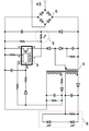
도 2를 참조하면, 종래의 기술에 따른 전원공급장치(SMPS)에서, 발진 IC(30)에서 트랜스포머(10)로 PWM 신호가 제공되어, 발진 IC(30)의 PWM 신호에 의해 트랜스포머(10)의 2차 권선부(TL2) 및 3차 권선부(TL3)에 유도기전력이 생성되고, 트랜스포머(10)의 3차 권선부(TL3)에서 출력되는 교류전원이 제1 출력정류부(40)에 의해 직류전원으로 변환된다.Referring to FIG. 2, in a power supply device (SMPS) according to the related art, a PWM signal is provided from the oscillation IC 30 to the
이러한 제1 출력정류부(40)에서 출력되는 직류전원의 전압을 피드백회로부(50)가 체크하고, 피드백 회로부(50)에서 발진 IC(30)로 입력되는 전압에 의해 발진 IC(30)에서 PWM 신호의 펄스폭을 제어함으로써, LED 모듈(60)의 부하 변동에 상관없이 트랜스포머(10)의 3차 권선부(TL3)에서 제1 출력정류부(40)를 통해 LED 모듈(60)로 정전류가 출력된다.The
이때, 상기 PFC 회로부(20)는 브릿지 다이오드(DB1)에서 접속되는 인덕터(L1, L2) 및 상기 인덕터(L1, L2) 사이에 접속되는 제3 콘덴서(C3)로 구성된다. 상기 PFC 회로부(20)는 인덕터(L1, L2)의 임피던스 양으로 제2 콘덴서(C3)의 충전전류가 제한되어, 도통각이 넓어지고 역률이 개선된다. 여기서, 도면부호 R1 및 R2는 댐핑저항이고, D6은 서지 방지를 위한 다이오드이다.In this case, the
또한, 상기 발진 IC(30)는 입력단(C)으로 입력되는 입력전압이 기준전압에 비해 낮으면, 출력단(D)에서 펄스폭이 큰 PWM 신호를 출력하여, 트랜스포머(10)의 출력전압을 높이고, 입력단(C)으로 입력되는 입력전압이 기준전압에 비해 높으면, 출력단(D)에서 펄스폭이 작은 PWM 신호를 출력하여, 트랜스포머(10)의 출력전압을 낮춘다.In addition, when the input voltage input to the input terminal C is lower than the reference voltage, the oscillation IC 30 outputs a PWM signal having a large pulse width at the output terminal D, thereby increasing the output voltage of the
상기 제1 출력정류부(40)는 3차 권선부(TL3)로 변압된 교류 전원을 직류전원으로 변환하는 다이오드(D4)와 콘덴서(C11)로 구성된다.The
상기 피드백 회로부(50)는 제1 출력 정류부(40)에서 출력되는 전압의 크기에 따라 흐르는 전류의 크기가 변하여 종속 전류원의 역할을 하는 포토커플러(PC1; photo coupler); 3차 권선부(TL3)에서 제1 출력 정류부(40)를 통해 출력되는 전압을 결정하기 위한 제1 제너다이오드(ZD1); 초기 동작시 포토커플러(PC1)로 제공되는 전류를 지연시키는 소프트 스타트부(51); 포토커플러(PC1)에 의해 동작이 제어되며, 트랜스포머(10)의 2차 권선부(TL2)에서 발진IC(30)로 제공되는 전압을 제어하는 제1 트랜지스터(TR1); 및 상기 제1 트랜지스터의 스위칭을 제어하는 정전류 및 온도보상부(52)로 구성된다.The
또한, 부온도 특성의 서미스터(Th1)는 제2 트랜지스터(TR2)의 바이어스 전압을 낮추어주어, 제2 트랜지스터(TR2)의 온도가 상승되는 만큼 정전류 제2 트랜지스터(TR2)의 전류 증폭도를 낮추어 준다. 도 1에 도시된 도면부호 70은 퓨즈(F1)를 통해 입력되는 교류 입력전원을 필터링하는 교류 입력필터이며, 배리스터(TR1), 제1 콘덴서(C1), 라인필터(LF) 및 제2 콘덴서(C2)로 구성된다.In addition, the thermistor Th1 having the negative temperature characteristic lowers the bias voltage of the second transistor TR2, thereby lowering the current amplification degree of the constant current second transistor TR2 as the temperature of the second transistor TR2 increases.
전술한 전원공급장치(SMPS)에 따르면, 교류 입력전원을 정류하는 브릿지 다이오드(DB1)와 상기 브릿지 다이오드(DB1)에서 출력되는 맥류를 변압하는 트랜스포머(10) 사이에 역률보상회로(20)가 배치되어, 맥류의 특성 개선을 통해 역률이 향상된다.According to the aforementioned power supply device SMPS, the power
그러나 전술한 전원공급장치(SMPS)의 경우, 포토커플러(PC1; photo coupler) 및 2차측 전류 컨트롤 회로 등이 필요하다는 문제점이 있고, 이를 제거하기 위해서 1차측 정전류 제어 기능을 갖는 LED 드라이버 IC가 사용될 수 있다.However, the above-described power supply device (SMPS) has a problem in that a photo coupler (PC1) and a secondary side current control circuit are required, and an LED driver IC having a primary side constant current control function is used to eliminate the above problem. Can be.
한편, 도 3은 1차측 정전류 제어 기능을 갖는 LED 드라이버 IC의 일반적인 애플리케이션 회로도이다.3 is a general application circuit diagram of an LED driver IC having a primary side constant current control function.
도 3을 참조하면, 1차측 정전류 제어 기능을 갖는 LED 드라이버 IC의 일반적인 애플리케이션은 1차측 정전류 제어 기능을 갖는 LED 드라이버 IC(81), 브릿지 다이오드(82) 및 트랜스포머(83)를 포함하고, Rv(84)에 의해 설정된 출력 전력에 의해 LED 모듈(85)을 구동한다.Referring to FIG. 3, a general application of an LED driver IC having a primary side constant current control function includes an LED driver IC 81 having a primary side constant current control function, a
상기 1차측 정전류 제어 기능을 갖는 LED 드라이버 IC(81)는 깜박임 없는 위상 제어 트라이액(TRIAC) 디밍 기능, 단일 PFC 및 정확한 정전류(CC) 출력이 가능하며, 포토커플러 및 모든 2차측 전류 컨트롤 회로가 필요 없는 IC로서, 예를 들면, 모델명 LNK409EG일 수 있다.The LED driver IC 81 with primary side constant current control is capable of flicker-free phase controlled triac (DIAC) dimming, single PFC and accurate constant current (CC) outputs, a photocoupler and all secondary side current control circuits. As an unnecessary IC, for example, the model name LNK409EG may be used.
상기 1차측 정전류 제어 기능을 갖는 LED 드라이버 IC(81)는 66㎑ 발진주파수로 효율을 극대화하고, 소형, 경량으로 8[W]에서 50[W]까지의 대용량의 SMPS가 가능하며, 발진주파수에 의한 노이즈 발생의 최소화 및 돌입전류의 최소화와 EMI를 동시에 해결할 수 있다.The LED driver IC 81 having the primary-side constant current control function maximizes efficiency at 66 kHz oscillation frequency, and enables large-scale SMPS from 8 [W] to 50 [W] in small size and light weight. Minimize noise generation, inrush current, and EMI at the same time.
그러나 이러한 LED 드라이버 IC(81)에서 제시하는 기존 회로 가운데 정전압 출력, 정전류 출력, 고조파 제한, 돌입전류 제한, EMI/EMC 대책, 리플전압 및 리플전류의 제한 및 발열 제한 등을 해결해야 되는데, 이로 인해 상기 LED 드라이버 IC(81)를 현장에 용이하게 적용하기 어렵다는 문제점이 있다. 이에 따라 전술한 조건 등을 만족할 수 있는 회로의 보강 및 시정수 설정이 필요한 실정이다.However, among the existing circuits proposed by the
전술한 문제점을 해결하기 위한 본 발명이 이루고자 하는 기술적 과제는, 가변 시정수를 이용하여 입력전압을 정합함으로써 노이즈 발생을 방지하고, 전원의 돌입전류 발생을 방지하는 정전류 제어 기능을 구비한 LED 조명용 SMPS를 제공하기 위한 것이다.The technical problem to be solved by the present invention to solve the above problems is, SMPS for LED lighting having a constant current control function to prevent the generation of noise, by preventing the inrush current generation by matching the input voltage using a variable time constant It is to provide.
본 발명이 이루고자 하는 다른 기술적 과제는, 고조파 제거를 위한 입력 필터를 이중화함으로써 충분한 보호 기능을 갖는 정전류 제어 기능을 구비한 LED 조명용 SMPS를 제공하기 위한 것이다.Another technical problem to be achieved by the present invention is to provide a SMPS for LED lighting having a constant current control function having a sufficient protection function by dualizing an input filter for harmonics removal.
본 발명이 이루고자 하는 또 다른 기술적 과제는, 다양한 공급 전원에서도 출력의 안정화를 기할 수 있는 전류 제어 기능을 구비한 LED 조명용 SMPS를 제공하기 위한 것이다.Another technical problem to be achieved by the present invention is to provide an SMPS for LED lighting having a current control function capable of stabilizing the output even in various power supplies.
전술한 기술적 과제를 달성하기 위한 수단으로서, 본 발명에 따른 정전류 제어 기능을 구비한 LED 조명용 전원공급장치(SMPS)는, 정전류 방식의 발광다이오드(LED) 조명용 전원공급장치(Switching-Mode Power Supply: SMPS)에 있어서, 입력되는 AC 전원을 정류하여 DC 전원으로 변환하는 브릿지 다이오드(Bridge Diode); 상기 브릿지 다이오드로부터 출력되는 DC 전원을 승압 또는 강압하는 트랜스포머(Transformer); 상기 브릿지 다이오드 및 상기 트랜스포머 사이에 배치되어, 상기 트랜스포머의 1차측 정전류 제어 기능을 구비하는 LED 드라이버 IC; 상기 LED 드라이버 IC에 연결되어 가변 시정수를 통해 입력 전원을 정합하는 입력전원 정합부; 및 상기 LED 드라이버 IC 및 상기 입력전원 정합부 사이에 연결되어 부하인 LED 조명등의 변화에 대응하여 적응적으로 시정수를 선정하는 부하변화 적응 시정수 선정부를 포함하여 구성된다.As a means for achieving the above-described technical problem, the LED lighting power supply (SMPS) with a constant current control function according to the present invention, a switching current-mode LED lighting power supply (Switching-Mode Power Supply: An SMPS comprising: a bridge diode for rectifying an input AC power and converting the input AC power into a DC power; A transformer for boosting or stepping down the DC power output from the bridge diode; An LED driver IC disposed between the bridge diode and the transformer and having a primary side constant current control function of the transformer; An input power matching unit connected to the LED driver IC to match input power through a variable time constant; And a load change adaptive time constant selecting unit connected between the LED driver IC and the input power matching unit to adaptively select a time constant in response to a change in the LED lighting lamp as a load.
여기서, 상기 입력전원 정합부는 상기 LED 드라이버 IC에 연결되는 가변 저항 및 커패시터에 의해 가변 시정수를 선정하며, 상기 가변 시정수에 의해 정합되는 입력 전원의 범위는 90[V]내지 235[V]일 수 있다.The input power matching unit selects a variable time constant by a variable resistor and a capacitor connected to the LED driver IC, and the range of input power matched by the variable time constant is 90 [V] to 235 [V]. Can be.
여기서, 상기 LED 드라이버 IC 및 상기 트랜스포머의 2차 권선 사이에 연결되어 정전류를 출력하는 기준 전압을 정합하도록 시정수를 선정하는 기준전압 정합용 시정수 선정부를 추가로 포함할 수 있다.Here, the reference voltage matching time constant selection unit for selecting a time constant to match the reference voltage for outputting a constant current is connected between the LED driver IC and the secondary winding of the transformer may further include.
여기서, 상기 AC 입력전원의 양단에 연결되어 상기 AC 입력전원의 입력에 따른 돌입 전류 발생을 방지하는 입력단 필터부를 추가로 포함할 수 있다.Here, the input terminal may further include an input stage filter unit connected to both ends of the AC input power to prevent inrush current generation according to the input of the AC input power.
여기서, 상기 AC 입력전원 및 상기 브릿지 다이오드 사이에 배치되어 고조파 제한을 위한 시정수를 설정하는 고조파 제한용 시정수 선정부를 추가로 포함할 수 있다.Here, the harmonic limiting time constant selection unit may be further disposed between the AC input power and the bridge diode to set a time constant for harmonic limitation.
여기서, 상기 고조파는 3차, 5차, 7차, 9차 및 11차 고조파이고, 상기 고조파 제한용 시정수 선정부는 3차 고조파를 30% 이하, 5차 고조파를 10% 이하, 7차 고조파를 7% 이하, 9차 고조파를 5% 이하, 및 11차 고조파를 3% 이하로 제한하는 것을 특징으로 한다.Here, the harmonics are 3rd, 5th, 7th, 9th, and 11th harmonic pie, the harmonic limiting time constant selector is 30% or less of the 3rd harmonic, 10% or less of the 5th harmonic, 7th harmonic 7% or less, 9th harmonic is 5% or less, and 11th harmonic is limited to 3% or less.
여기서, 상기 트랜스포머(T1)로부터 출력되어 정류 및 필터링된 직류전원을 LED 조명등인 부하의 변동에 따라 자동으로 정전압 및 전류용량을 변환하는 자동 정전압 및 전류용량 변환부를 추가로 포함할 수 있다.Here, the rectified and filtered DC power output from the transformer T1 may further include an automatic constant voltage and current capacity conversion unit for automatically converting the constant voltage and the current capacity according to the variation of the load, such as an LED lamp.
여기서, 상기 트랜스포머의 저발열을 위해 상기 트랜스포머의 2차 권선에 배치되어 시정수를 선정하는 트랜스포머 시정수 선정부를 추가로 포함할 수 있다.Here, the transformer may further include a transformer time constant selection unit disposed in the secondary winding of the transformer to select a time constant for low heat generation of the transformer.
여기서, 상기 AC 입력전원 및 상기 브릿지 다이오드 사이에 배치되는 라인 필터로서, EMI/EMC 저감을 위해 상기 AC 전원 라인에 포함되어 있는 잡음을 제거하는 EMI/EMC 저감부를 추가로 포함할 수 있다.The line filter disposed between the AC input power and the bridge diode may further include an EMI / EMC reduction unit for removing noise included in the AC power line to reduce EMI / EMC.
본 발명에 따르면, 수동 회로에 의한 가변 시정수를 이용하여 입력전압을 정합함으로써 노이즈 발생을 방지하고, 전원의 돌입전류 발생을 방지하며, 고조파 제거를 위한 입력 필터를 이중화함으로써 충분한 보호 기능을 갖출 수 있다. 예를 들면, 운영 방식이 2등용으로 구성된 LED 형광등의 내부에 장착되어 돌입전류의 발생을 방지할 수 있고, 고조파를 제거할 수 있다.According to the present invention, the input voltage is matched using a variable time constant by a passive circuit to prevent noise generation, to prevent inrush current generation of the power supply, and to provide sufficient protection by dualizing an input filter for removing harmonics. have. For example, an operating method may be mounted inside an LED fluorescent lamp configured for two lamps to prevent generation of inrush current and to remove harmonics.
본 발명에 따르면, 다양한 공급 전원에서도 출력의 안정화를 기할 수 있고, 예를 들면, 1등용 전환시 LED 조명등에 안정적인 전원을 공급할 수 있다.According to the present invention, the output can be stabilized even in a variety of power supplies, for example, it is possible to supply a stable power to the LED light when switching for one lamp.
본 발명에 따르면, 트랜스포머의 저발열과 EMI/EMC를 동시에 해결함으로써 전자식 안정기의 사용에 안정성을 확보할 수 있다.According to the present invention, it is possible to secure stability in the use of the electronic ballast by simultaneously solving the low heat generation of the transformer and EMI / EMC.
본 발명에 따르면, 저전력으로 조명 에너지의 사용량의 절감시킬 수 있으며, 이에 따라 이산화탄소 저감을 위한 저탄소 정책 및 지구온난화 방지에 기여할 수 있다.According to the present invention, it is possible to reduce the use of lighting energy at low power, thereby contributing to a low carbon policy and global warming prevention for carbon dioxide reduction.
도 1은 종래의 기술에 따른 발광 다이오드 조명장치를 나타내는 도면이다.
도 2는 종래의 기술에 따른 SMPS를 나타내는 회로도이다.
도 3은 1차측 정전류 제어 기능을 갖는 LED 드라이버 IC의 일반적인 애플리케이션 회로도이다.
도 4는 본 발명의 실시예에 따른 정전류 제어 기능을 구비한 발광다이오드 조명용 SMPS의 동작 과정을 설명하기 위한 도면이다.
도 5는 도 4에 도시된 1차측 정전류 제어 기능을 갖는 LED 드라이버 IC의 핀 구성을 예시하는 도면이다.
도 6은 도 4에 도시된 1차측 정전류 제어 기능을 갖는 LED 드라이버 IC의 기능 블록 다이어그램이다.
도 7은 본 발명의 실시예에 따른 정전류 제어 기능을 구비한 LED 조명용 SMPS의 구성도이다.
도 8은 본 발명의 실시예에 따른 정전류 제어 기능을 구비한 LED 조명용 SMPS의 회로도이다.
도 9는 본 발명의 다른 실시예에 따른 정전류 제어 기능을 구비한 LED 조명용 SMPS의 회로도이다.1 is a view showing a light emitting diode lighting apparatus according to the prior art.
2 is a circuit diagram illustrating a SMPS according to the related art.
3 is a general application circuit diagram of an LED driver IC having a primary side constant current control function.
4 is a view for explaining the operation of the SMPS for LED lighting with a constant current control function according to an embodiment of the present invention.
FIG. 5 is a diagram illustrating a pin configuration of the LED driver IC having the primary side constant current control function shown in FIG. 4.
FIG. 6 is a functional block diagram of an LED driver IC having the primary side constant current control function shown in FIG. 4.
7 is a block diagram of a SMPS for LED lighting having a constant current control function according to an embodiment of the present invention.
8 is a circuit diagram of a SMPS for LED lighting having a constant current control function according to an embodiment of the present invention.
9 is a circuit diagram of a SMPS for LED lighting having a constant current control function according to another embodiment of the present invention.
아래에서는 첨부한 도면을 참조하여 본 발명이 속하는 기술분야에서 통상의 지식을 가진 자가 용이하게 실시할 수 있도록 본 발명의 실시예를 상세히 설명한다. 그러나 본 발명은 여러 가지 상이한 형태로 구현될 수 있으며 여기에서 설명하는 실시예에 한정되지 않는다. 그리고 도면에서 본 발명을 명확하게 설명하기 위해서 설명과 관계없는 부분은 생략하였으며, 명세서 전체를 통하여 유사한 부분에 대해서는 유사한 도면 부호를 붙였다.DETAILED DESCRIPTION Hereinafter, exemplary embodiments of the present invention will be described in detail with reference to the accompanying drawings so that those skilled in the art may easily implement the present invention. The present invention may, however, be embodied in many different forms and should not be construed as limited to the embodiments set forth herein. In the drawings, parts irrelevant to the description are omitted in order to clearly describe the present invention, and like reference numerals designate like parts throughout the specification.
명세서 전체에서, 어떤 부분이 어떤 구성요소를 "포함"한다고 할 때, 이는 특별히 반대되는 기재가 없는 한 다른 구성요소를 제외하는 것이 아니라 다른 구성요소를 더 포함할 수 있는 것을 의미한다.Throughout the specification, when a part is said to "include" a certain component, it means that it can further include other components, without excluding other components unless specifically stated otherwise.
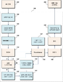
도 4는 본 발명의 실시예에 따른 정전류 제어 기능을 구비한 발광다이오드 조명용 SMPS의 동작 과정을 설명하기 위한 도면이다.4 is a view for explaining the operation of the SMPS for LED lighting with a constant current control function according to an embodiment of the present invention.
도 4를 참조하면, 본 발명의 실시예에 따른 정전류 제어 기능을 구비한 발광다이오드 조명용 SMPS(100)는 브릿지 다이오드(110), 1차측 정전류 제어 기능을 갖는 LED 드라이버 IC(120), 트랜스포머(130), 정류기(160) 및 필터(170) 등을 포함함으로써, AC 전원(200)을 입력받아 LED 모듈인 조명등(300)을 구동하게 된다.Referring to FIG. 4, the
본 발명의 실시예에 따른 정전류 제어 기능을 구비한 발광다이오드 조명용 SMPS(100)는, AC -> DC -> 스위칭(발진) -> 트랜스포머 권수에 의한 승압/강압 -> 정류 -> 필터 -> DC 전압의 과정을 거치면서, 66㎑ 이상의 발진 주파수를 사용하는 방식이다. 이때, 상기 정전류 제어 기능을 구비한 발광다이오드 조명용 SMPS(100)는 단일 PFC(역률보정) 및 정전류 컨트롤러가 내장된 1차측 정전류 제어 기능을 갖는 LED 드라이버 IC(120)를 사용함으로써, 2차측 전류 컨트롤 회로 없이도 정확한 정전류 제어가 가능하며, 이에 따라 2차측 회로를 단순화할 수 있게 된다.SMPS (100) for LED lighting having a constant current control function according to an embodiment of the present invention, AC-> DC-> switching (oscillation)-> step-up / step-down by transformer winding-> rectification-> filter-> DC Through the process of voltage, the oscillation frequency of 66 kHz or more is used. At this time, the light emitting
본 발명의 실시예에 따른 정전류 제어 기능을 구비한 LED 조명용 전원공급장치(SMPS)는 안정된 전원 공급을 위하여 1차측 정전류 제어 기능을 가진 LED 드라이버 IC(예를 들면, LNK 409EG)를 이용한 SMPS 전원공급장치로서, 수동 회로를 이용한 노이즈 및 전원의 돌입전류를 방지하는 돌입전류 방지부 및 고조파 제거를 위한 필터를 이중화하여 충분한 보호 기능을 갖추며, 다양한 공급 전원에서도 출력의 안정화를 기할 수 있는 기능을 포함한다.LED lighting power supply (SMPS) having a constant current control function according to an embodiment of the present invention is SMPS power supply using an LED driver IC (for example, LNK 409EG) having a primary constant current control function for stable power supply As a device, it has a sufficient protection function by duplexing the inrush current prevention part that prevents noise and inrush current of power supply using passive circuit, and the filter for eliminating harmonics, and also includes the function to stabilize the output even in various power supply. .
이를 위한 회로 설계 및 시정수, 사용 등기구 수에 맞는 정전압, 정전류 출력이 가능하도록 전압 및 정전류 설계 및 시정수, 트랜스포머의 시정수가 50W까지 가능하도록 재설정함으로써 저발열이 가능하다.Low heat generation is possible by resetting the voltage and constant current design, time constant, and transformer's time constant to allow 50W for constant voltage and constant current according to the circuit design and time constant and the number of luminaires used.
한편, 도 5는 도 4에 도시된 1차측 정전류 제어 기능을 갖는 LED 드라이버 IC의 핀 구성을 예시하는 도면이고, 도 6은 도 4에 도시된 1차측 정전류 제어 기능을 갖는 LED 드라이버 IC의 기능 블록 다이어그램이다.Meanwhile, FIG. 5 is a diagram illustrating a pin configuration of the LED driver IC having the primary side constant current control function shown in FIG. 4, and FIG. 6 is a functional block of the LED driver IC having the primary side constant current control function shown in FIG. 4. It is a diagram.
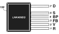
도 5 및 도 6을 참조하면, 1차측 정전류 제어 기능을 갖는 LED 드라이버 IC(120)는 DRAIN 7번 핀(D), SOURCE 5번 핀(S), BYPASS 4번 핀(BP), FEEDBACK 3번 핀(FB), REFERENCE 1번(R) 핀 및 VOLTAGE MONITOR 2번 핀(V)을 구비한다.5 and 6, the
DRAIN 7번 핀(D)은 파워 MOSFET 드레인 연결 핀으로서, 스타트업 및 정상 상태 작동을 위한 내부 작동 전류를 제공한다.DRAIN pin 7 (D) is a power MOSFET drain connection pin that provides internal operating current for startup and steady-state operation.
SOURCE 5번 핀(S)은 파워 MOSFET 소스 연결 핀으로서, BYPASS(BP), FEEDBACK(FB), REFERENCE(R) 및 VOLTAGE MONITOR(V) 핀들에 대한 그라운드 레퍼런스 핀이다.
BYPASS 4번 핀(BP)은 내부적으로 생성된 5.9V 공급을 위한 외부 바이패스 커패시터의 연결 지점으로서, BYPASS 핀(BP) 커패시터 값 선택을 통한 출력 전력을 선택할 수 있다.BYPASS pin 4 (BP) is the connection point for an internally generated external bypass capacitor for the 5.9V supply, and the output power can be selected by selecting the BYPASS pin (BP) capacitor value.
FEEDBACK 3번 핀(FB)은 출력 전압 피드백에 사용된다. FEEDBACK 핀으로 흐르는 전류는 출력 전압에 직접적으로 비례합니다. 또한 FEEDBACK 핀에는 오픈 부하 및 과부하 출력 상태로터 보호하기 위한 회로가 포함되어 있습니다.FEEDBACK pin 3 (FB) is used for output voltage feedback. The current flowing into the FEEDBACK pin is directly proportional to the output voltage. The FEEDBACK pin also contains circuitry to protect the open load and overload output states.
REFERENCE 2번 핀(R)은 외부 정밀 저항에 연결되고, 작동의 디밍 및 비TRIAC 디밍 모드 간의 선택에 사용된다.REFERENCE pin 2 (R) is connected to an external precision resistor and is used to select between dimming and non-TRIAC dimming modes of operation.
VOLTAGE MONITOR 1번 핀(V)은 정류기, 필터 커패시터 및 저항으로 구성되는 외부 입력 라인 피크 감지기와 상호 작용하며, 이때, 적용된 전류는 입력 저전압(UV) 및 과전압(OV)에 대한 정지 로직(stop logic)을 제어하고, 출력 전류 및 원격 ON/OFF 기능 제어를 위한 피드포워드(Feed forward)를 제공하는데 사용된다.VOLTAGE MONITOR pin 1 (V) interacts with an external input line peak detector consisting of a rectifier, filter capacitor, and resistor, where the applied current is the stop logic for the input undervoltage (UV) and overvoltage (OV). ) And feed forward for controlling the output current and remote ON / OFF functions.
구체적으로, 1차측 정전류 제어 기능을 갖는 LED 드라이버 IC(120)는 TRIAC 디밍 기능, 단일 PFC, 1차측 정전류 컨트롤 기능을 가진 LED 드라이버 IC로서, 역률(PF) > 0.9, TRIAC 디밍 기능 및 고효율이 요구되는 LED 드라이브의 구현이 매우 용이해진다. 단일 역률(PF) 및 정전류 컨트롤러를 사용하여 역률 수정 및 전해 평활 커패시터에 필요한 패시브 회로가 불필요하게 된다. 이러한 1차측 컨트롤 기술은 광-커플러 및 2차측 전류 컨트롤 회로를 필요 없게 하고, 정확한 정전류 컨트롤을 가능하게 한다. 또한, 725V 파워 MOSFET, 연속 모드 PWM 컨트롤러, 셀프 바이어스용 고전압 스위칭 전류 소스, 주파수 지터링, 사이클별 전류 제한, 히스테리시스 서멀 셧다운 회로 등이 모두 모놀리식 IC로 통합되어 있다.Specifically, the
이하, 도 7 및 도 9를 참조하여, 본 발명의 실시예로서, LNK 409EG를 이용한 LED 2등용 전원 장치(SMPS)의 동작 및 기능에 대하여 설명한다.Hereinafter, with reference to FIGS. 7 and 9, the operation and function of the LED two-light power supply device (SMPS) using the LNK 409EG will be described.
한편, 도 7은 본 발명의 실시예에 따른 정전류 제어 기능을 구비한 발광다이오드 조명용 SMPS의 구성도이고, 도 8은 본 발명의 실시예에 따른 정전류 제어 기능을 구비한 발광다이오드 조명용 SMPS의 회로도이다.On the other hand, Figure 7 is a block diagram of a light emitting diode illumination SMPS with a constant current control function according to an embodiment of the present invention, Figure 8 is a circuit diagram of a light emitting diode illumination SMPS with a constant current control function according to an embodiment of the present invention. .
도 7 및 도 8을 참조하면, 본 발명의 실시예에 따른 정전류 제어 기능을 구비한 발광다이오드 조명용 SMPS(100)는, AC 입력전원(200)을 수신하여 DC로 변환하여 LED 모듈(300)에 제공하며, 브릿지 다이오드(110), LED 드라이버 IC(120), 트랜스포머(130) 및 추가회로를 포함하고, 상기 추가회로는 입력전원 정합부(가변 시정수 선정)(141), 부하변화 적응 시정수 선정부(142), 기준전압 정합용 시정수 선정부(143), 입력단 필터부(144), 고조파 제한용 시정수 선정부(145), 자동 정전압 및 전류용량 변환부(146), 트랜스포머 시정수 선정부(147) 및 EMI/EMC 저감부(148)를 포함한다.7 and 8, the
브릿지 다이오드(110)는 AC 입력 전원을 정류하여 DC로 변환하며, 즉, 상기 브릿지 다이오드(BD1)는 상용 교류 전원, 예를 들면, AC 220V의 전원을 정류하여 직류 전압을 가지는 직류 전원을 생성한다. 여기서, 브릿지 다이오드(BD1)에서 출력되는 전압값은 교류 입력 전압 값 및 발광다이오드의 수에 따라 적절하게 결정될 수 있고, 이때, 브릿지 다이오드(BD1)에서 출력되는 직류 전원은 직류 성분과 교류 성분이 함께 포함된 맥류 전원이다.The
트랜스포머(130)는 브릿지 다이오드(110)로부터 제공되는 DC 전압을 승압한다.The
LED 드라이버 IC(120)는 1차측 정전류 제어 기능을 갖는 IC로서, 전술한 바와 같이 LNK409EG일 수 있고, 상기 LNK409EG는 1차측 정전류 제어 기능을 가진 LED 드라이버 IC로서, LED 조명장치를 고효율로 역률 0.9 이상으로 출력할 수 있고, 시정수 선택에 따라 90[V]에서 235[V]의 전압을 입력할 수 있는 LED용 드라이버 IC이다.The
구체적으로, 도 8을 참조하면, 상기 LED 드라이버 IC(120)의 REFERENCE 1번 핀은 외부 저항을 통해 그라운드(SOURCE)에 연결되고, 선택한 값에 따라 내부 기준이 설정되고 디밍 및 비디밍 동작 간의 작동 모드와 VOLTAGE MONITOR 핀의 입력 저전압 및 과전압 기준값이 결정되며, 저항 허용 오차가 출력 오차에 직접적인 영향을 주므로 1% 저항이 권장된다.Specifically, referring to FIG. 8, the
또한, 상기 LED 드라이버 IC(120)의 스위칭 주파수는 66㎑로서, EMI 레벨을 더 줄이기 위해 상기 스위칭 주파수는 약 ㅁ1㎑만큼 지터(Jitter)된다.In addition, the switching frequency of the
퓨즈(F1)는 부품 오류 보호 기능을 제공하고, 제1 트라이액(TH1)은 차동 입력 서지 동안에 클램핑을 하면서, 상기 LED 드라이버 IC(120) 내부의 파워 MOSFET의 정격보다 작게 LED 드라이버 IC(120)의 피크 드레인 전압을 유지한다. 브릿지 정류기(BD1)는 AC 입력 전압을 정류한다. 또한, 트랜스포머(T1)의 1차측 및 2차측 간의 안전 절연 배리어를 브릿지하는 C14 커패시터와 함께 L1~L4 코일, C1 커패시터, R2 및 R3 저항은 EMI 필터링을 제공한다.The fuse F1 provides component fault protection, and the first triac TH1 clamps during the differential input surge, while the
이때, 상기 R2 및 R3 저항은 L1 및 L2 코일, C1 커패시터 및 AC 입력 임피던스 간에 형성된 모든 공진을 댐핑하도록 작동한다. 1차측 스위칭 전류를 위한 낮은 임피던스 소스를 제공하려면, 소형 평활 커패시터(C3)가 필요하며, 역률(PF)을 0.9보다 크게 유지하기 위해서 C1 및 C3 커패시터의 최대값이 제한된다.At this time, the R2 and R3 resistors operate to damp any resonance formed between the L1 and L2 coils, the C1 capacitor and the AC input impedance. To provide a low impedance source for the primary side switching current, a small smoothing capacitor C3 is required, and the maximum value of the C1 and C3 capacitors is limited to keep the power factor PF greater than 0.9.
또한, 피크 입력 전압 정보를 LED 드라이버 IC(120)에 제공하기 위해 들어오는 정류된 AC 피크는 D1 다이오드를 통해 C4 커패시터를 충전하며, 이후, R6 및 R7저항을 통해 LED 드라이버 IC(120)의 VOLTAGE MONITOR 2번 핀(V)에 센싱 전류로 공급된다. 또한, 상기 LED 드라이버 IC(120)는 라인 입력 과전압 및 저전압 보호 기준값을 설정하기 위해 상기 센싱 전류를 사용한다. 이때, R5 저항은 입력 주파수 리플이 생성되는 것을 방지하기 위해서 정류된 AC의 시정수보다 훨씬 긴 시정수를 가진 C4 커패시터에 방전 경로를 제공한다.In addition, the rectified AC peak to provide peak input voltage information to the
VOLTAGE MONITOR 2번 핀(V)의 센싱 전류와 FEEDBACK 3번 핀(FB)의 전류는 평균 출력의 LED 전류를 제어하기 위해 내부적으로 사용된다. 예를 들면, 제1 TRIAC(TH1) 위상 디밍 애플리케이션의 경우, 입력 전압 및 출력 전류 간의 선형 관계를 제공하고, 디밍 범위를 극대화하기 위해 R4 저항이 REFERENCE 1번 핀(R)에 사용되고, R6 및 R7 저항이 VOLTAGE MONITOR 2번 핀(V)에 사용된다. 또한, R4 저항은 내부 라인 입력 저전압 및 과전압 보호 기준값을 설정한다.The sensing current on
또한, D3 다이오드는 누설 인덕턴스의 영향으로 인해 드레인 전압을 안전한 레벨로 클램핑한다. 또한, C3 양단 전압이 리플렉트 출력 전압(VOR) 아래로 내려가는 정류된 AC 입력 전압 기간 동안에 역방향 전류가 상기 LED 드라이버 IC(120)을 통과하는 것을 방지하기 위해 다이오드 D3이 필요하다.In addition, the D3 diode clamps the drain voltage to a safe level due to the effect of leakage inductance. In addition, diode D3 is required to prevent reverse current from passing through the
또한, D6 다이오드, C11 커패시터, R14 및 R15 저항은 트랜스포머(T1)의 보조 권선에서 1차측 바이어스 서플라이를 만든다. C10 커패시터는 내부 컨트롤러용 서플라이 핀에 해당하는 상기 LED 드라이버 IC(120)의 BYPASS 4번 핀(BP)을 위한 로컬 디커플링을 제공한다. 이에 따라 스타트업 동안에 C10 커패시터는 상기 LED 드라이버 IC(120)의 DRAIN 7번 핀(D)에 연결된 내부 고전압 전류 소스에서 소정 전압으로 충전된다. 따라서 R12 저항을 통해 바이어스 서플라이에서 작동 공급 전류가 제공되는 지점에서 상기 LED 드라이버 IC(120)가 스위칭을 시작할 수 있다. 또한, 상기 C10 커패시터는 출력 전력 모드를 선택할 수 있다.In addition, the D6 diode, C11 capacitor, R14 and R15 resistors make the primary side bias supply at the auxiliary winding of transformer T1. The C10 capacitor provides local decoupling for BYPASS pin 4 (BP) of the
한편, 바이어스 권선 전압은 출력 전압에 비례하며, 즉, 바이어스 및 2차측 권선 간의 턴수 비에 의해 설정된다. 따라서 트랜스포머(T1)의 2차측 피드백 부품 없이도 출력 전압을 모니터링할 수 있다. R13 저항은 바이어스 전압을 상기 LED 드라이버 IC(120)의 FEEDBACK 3번 핀(FB)에 공급되는 전류로 변환한다.On the other hand, the bias winding voltage is proportional to the output voltage, i.e., set by the turn ratio between the bias and the secondary winding. Thus, the output voltage can be monitored without the secondary feedback component of the transformer (T1). The resistor R13 converts the bias voltage into a current supplied to the
또한, 무부하에서 출력 전압을 제한하기 위해 출력 과전압 보호 회로가 D7 다이오드, C13 커패시터, R17 저항, ZD2 제너다이오드, C12 커패시터, Q1 트랜지스터 및 R16 저항에 의해 설정된다. 이때, 출력 부하가 연결 해제되는 경우, ZD2 제너다이오드가 도통될 때까지 바이어스 전압이 증가하며, Q1 트랜지스터는 ON 상태가 되고 FEEDBACK 3번 핀(FB)으로 흐르는 전류는 감소하게 된다. 예를 들면, 이러한 전류가 20㎂ 아래로 내려갈 경우, 상기 LED 드라이버 IC(120)는 오토-리스타트로 진입하고, 출력 및 바이어스 전압이 해당 시간 동안 떨어질 수 있도록 예를 들면, 800ms 동안 스위칭이 비활성화 된다.In addition, an output overvoltage protection circuit is set by the D7 diode, C13 capacitor, R17 resistor, ZD2 zener diode, C12 capacitor, Q1 transistor, and R16 resistor to limit the output voltage at no load. At this time, when the output load is disconnected, the bias voltage increases until the ZD2 zener diode becomes conductive, and the Q1 transistor is turned on and the current flowing to
또한, 트랜스포머(T1) 2차측 권선은 다이오드에 의해 정류되고 C6, C7 및 C8 커패시터에 의해 필터링된다. 이때, 피크 간 전류와 LED 리플 전류(Ripple Current)를 제공하기 위해서 C6, C7 및 C8 커패시터의 결합된 값이 선택된다. 보다 낮은 리플이 권장되는 설계의 경우, 출력 커패시턴스 값을 늘릴 수 있다.In addition, the transformer (T1) secondary winding is rectified by the diode and filtered by the C6, C7 and C8 capacitors. At this time, the combined values of the C6, C7, and C8 capacitors are selected to provide peak-to-peak current and LED ripple current. For designs where lower ripple is recommended, you can increase the output capacitance value.
또한, 상기 LED 드라이버 IC(120)는 TRIAC(TH1)을 기반으로 하는 낮은 가격의 리딩-Edge 위상 디머를 사용하여 출력 디밍을 제공해야 하는 요구 사항에 따라 여러 측면의 설계를 적용한다.In addition, the
구체적으로, LED 기반 조명이 훨씬 낮은 전력을 소비하므로 전체 램프가 끌어온 전류는 디머 내에 있는 TRIAC(TH1)의 유지 전류보다 작다. 이로 인해 TRIAC(TH1)가 불규칙적으로 작동할 때 제한된 디밍 범위 및/또는 깜박임과 같은 바람직하지 않은 동작이 발생할 수 있다. 예를 들면, LED 조명등이 라인에 제공하는 상대적으로 큰 임피던스 덕분에 TRIAC(TH1)가 ON 상태일 때, 입력 커패시턴스를 충전하는 돌입 전류로 인해 링잉(Ringing)이 크게 발생할 수 있다. 또한, 이 경우 링잉으로 인해 TRIAC(TH1) 전류가 0으로 내려가거나 OFF 상태가 되는 등의 원하지 않는 동작이 일어날 수 있다.Specifically, the LED-based light consumes much lower power, so the current drawn by the entire lamp is less than the holding current of TRIAC (TH1) in the dimmer. This may result in undesirable behavior, such as limited dimming range and / or flicker, when TRIAC TH1 operates irregularly. For example, when the TRIAC (TH1) is ON due to the relatively large impedance that the LED lamp provides to the line, the ringing can occur largely due to the inrush current charging the input capacitance. In this case, ringing may cause unwanted operation such as the TRIAC (TH1) current goes to zero or becomes OFF.
본 발명의 실시예에 따른 정전류 제어 기능을 구비한 발광다이오드 조명용 SMPS(100)에서 입력전원 정합부(141)는 1차측 정전류 제어 기능을 가진 LED 드라이버 IC(120)에서 가변 시정수를 통해 90[V]에서 235[V]의 입력 전원을 정합하며, 이때, R11, R19 저항 및 VR1 가변저항과 C10 커패시터를 통해 시정수를 선정할 수 있다.In the
부하변화 적응 시정수 선정부(142)는 부하인 LED 조명등의 변화에 대응하여 적응적으로 시정수를 선정한다. 예를 들면, SW1 스위치를 ON 시킴으로써, 전술한 R11, R19 저항 및 VR1 가변저항과 C10 커패시터를 통해 선정된 시정수를 R19 저항 및 VR1 가변저항과 C10 커패시터를 통해 시정수를 선정할 수 있다.The load change adaptive time
기준전압 정합용 시정수 선정부(143)는 LED 드라이버 IC(120)의 FEEDBACK 3번 핀(FB) 및 상기 트랜스포머의 2차 권선 사이에 연결되어 기준 전압을 정합하기 위해 시정수를 선정함으로써 정전류를 출력할 수 있다. 예를 들면, 전술한 바와 같이, 무부하에서 출력 전압을 제한하기 위해 출력 과전압 보호 회로가 D7 다이오드, C13 커패시터, R17 저항, ZD2 제너다이오드, C12 커패시터, Q1 트랜지스터 및 R16 저항에 의해 설정되는데, R17 및 R16 저항과 C13 및 C12 커패시터에 의해 시정수를 선정할 수 있다.The time
입력단 필터부(144)는 AC 입력전원의 양단에 연결되어 돌입 전류 발생을 방지하도록 이중화된다. 예를 들면, 입력단 필터부(144)는 제2 브릿지 다이오드(BD2), C20, C21 및 C22 커패시터, R20 및 R21 저항, D8 및 D9 다이오드, ZD3 및 ZD4 제너다이오드, 및 릴레이(RY1)로 구성될 수 있다.The input
고조파 제한용 시정수 선정부(145)는 AC 입력전원 및 브릿지 다이오드(BD1) 사이에 배치되어 3, 5, 7, 9, 11 고조파 제한을 위한 시정수를 설정하게 된다. 여기서, 고조파는 하나의 주파수를 형성하는 다른 주파수(예를 들면, 기본 주파수, 1차 고조파, 3차 고조파 등)를 말하며, 기본 주파수 이외의 성분들, 예를 들면, 3, 5, 7, 9, 11 고조파가 노이즈를 발생시키므로 이를 제거한다. 상기 고조파 제한용 시정수 선정부(145)는, 예를 들면, C15 및 C16 커패시터, Z1 배리스터(varistor), C17 커패시터, C1 커패시터, R2 및 R3 저항, L1 및 L2 코일을 포함할 수 있다.The harmonic limiting time
자동 정전압 및 전류용량 변환부(146)는 LED 조명등인 부하의 변동에 따라 자동 정전압 및 전류용량을 변환하기 위한 것으로, 상기 트랜스포머(T1)로부터 출력되어 정류 및 필터링된 직류전원을 L5 및 L6 코일, C9 및 C19 커패시터, R9 저항, ZD 제너다이오드 및 TH2 및 TH3 트라이액을 포함한다.The automatic constant voltage and current
트랜스포머 시정수 선정부(147)는 상기 트랜스포머(T1)의 저발열을 위해서 R18 저항 및 C18 커패시터에 의해 시정수를 선정한다.The transformer time
EMI/EMC 저감부(148)는 상기 AC 입력전원 및 브릿지 다이오드(BD1) 사이에 배치되는 라인 필터(LF1)로서 EMI/EMC 저감을 위한 것이다. 여기서, AC 전원 라인에 포함되어 있는 여러 가지 잡음을 제거하는 필터를 라인 필터(line filter)라고 하는데, 이러한 라인 필터는 코일과 콘덴서로 이루어진 저역 통과 필터(Low Pass Filter)이다.The EMI /
한편, 도 9는 본 발명의 다른 실시예에 따른 정전류 제어 기능을 구비한 발광다이오드 조명용 SMPS의 회로도이다.9 is a circuit diagram of a light emitting diode lighting SMPS having a constant current control function according to another embodiment of the present invention.
도 9를 참조하면, 본 발명의 다른 실시예에 따른 정전류 제어 기능을 구비한 발광다이오드 조명용 SMPS는, 전술한 도 8에 도시된 SMPS와 비교하면, 고조파 제한용 시정수 선정부(155) 및 EMI/EMC 저감부(158)의 구성이 다른 점을 제외하면, 다른 구성요소들은 실질적으로 동일하므로 동일한 부분에 대한 설명은 생략한다. 즉, 본 발명의 실시예에 따른 정전류 제어 기능을 구비한 발광다이오드 조명용 SMPS는 도 8 및 도 9에 각각 도시된 바와 같이, 고조파 제한용 시정수 선정부(145, 155) 및 EMI/EMC 저감부(146, 158)가 배치될 수 있다.Referring to FIG. 9, the light emitting diode lighting SMPS having the constant current control function according to another embodiment of the present invention is compared with the SMPS shown in FIG. 8, the harmonic limiting time
상기 고조파 제한용 시정수 선정부(155)는, 예를 들면, 상기 고조파 제한용 시정수 선정부(155)는 C1 커패시터, R2 및 R3 저항, L1 및 L2 코일이 AC 교류 전원 측에 배치되고, C15 및 C16 커패시터, Z1 배리스터(varistor), C17 커패시터가 브릿지 다이오드(BD1) 측에 배치된다. 이때, EMI/EMC 저감부(158)인 라인 필터(LF1)는 브릿지 다이오드(BD1) 측에 배치된다.In the harmonic limiting time
한편, 본 발명의 실시예에 따른 정전류 제어 기능을 구비한 발광다이오드 조명용 SMPS에 대한 전기적 특성 중 입력 특성은 다음과 같다. 정격 입력전압은 단상 250V/90V이고, 입력전압 범위는 ㅁ5%이며, 입력주파수 범위는 50㎐/60㎐이고, 입력 돌입전류는 0.2A 이하(모듈 단위)이고, 효율은 부하전류 85% 이상이고, 역률은 부하전류 90% 이상이며, 1차 돌입전류는 0.2A 이하이고, Vpp는 3V 미만으로 주어진다.On the other hand, the input characteristics of the electrical characteristics of the SMPS for light emitting diode illumination with a constant current control function according to an embodiment of the present invention are as follows. Rated input voltage is single phase 250V / 90V, input voltage range is ㅁ 5%, input frequency range is 50㎐ / 60㎐, input inrush current is 0.2A or less (module unit), efficiency is 85% or more load current The power factor is 90% or more of the load current, the primary inrush current is 0.2A or less, and Vpp is given as less than 3V.
또한, 본 발명의 실시예에 따른 정전류 제어 기능을 구비한 발광다이오드 조명용 SMPS에 대한 전기적 특성 중 직류 출력 특성은 다음과 같다. 정격 출력전압은 24V이고, 운용 전압 범위는 24V이며, 정격 출력전류는 0.8A/1등용 및 1.6A/2등용이고, 입력 및 부하에 대한 안정도는 1%이고, 2차 돌입전류는 0.1A∼0.2A 이내이고, 출력전류는 0.7A∼0.9 이내에서 제한되며, 출력 과전압 보호를 위해 24Vㅁ0.5V 이내에서 정류 모듈이 정지된다.In addition, DC output characteristics among the electrical characteristics of the SMPS for LED lighting having a constant current control function according to an embodiment of the present invention are as follows. Rated output voltage is 24V, operating voltage range is 24V, rated output current is for 0.8A / 1 lamp and 1.6A / 2 lamp, stability for input and load is 1%, secondary inrush current is 0.1A ~ Within 0.2A, the output current is limited within 0.7A to 0.9, and the rectifier module is stopped within 24V to 0.5V for output overvoltage protection.
또한, 본 발명의 실시예에 따른 정전류 제어 기능을 구비한 발광다이오드 조명용 SMPS에 대한 전기적 특성 중 환경조건은 다음과 같다. 먼저, 고주파 무선장애(EMI)에 있어서, 3방사방해파(30㎒∼1,000㎒)인 경우, 30㎒≤f≤250㎒: 10㎷(30㏈㎶) 이하이고, 250㎒≤f≤1,000㎒: 10㎷(37㏈㎶) 이하이며, 4방사방해파(9㎑∼300㎒)인 경우, 9㎑≤f≤110㎒: 30㏈㎶로 주어진다. 또한, ISO 61000-기반의 고조파에 있어서, 2차 고조파는 2% 이하, 3차 고조파는 30% 이하(역률 0.9 경우, 27% 이하), 5차 고조파는 10% 이하, 7차 고조파는 7% 이하, 9차 고조파는 5% 이하, 그리고 11차 고조파는 3% 이하가 되게 한다. 또한, 동작 온도 및 습도에 있어서, 온도는 -30℃∼+60℃로 주어지고, 습도는 10%∼90%로 주어진다.In addition, the environmental conditions of the electrical characteristics of the SMPS for LED lighting with a constant current control function according to an embodiment of the present invention are as follows. First, in high frequency radio interference (EMI), in the case of three radiation waves (30 MHz to 1,000 MHz), 30 MHz ≤ f ≤ 250 MHz: 10 Hz (30 Hz) or less, and 250 MHz ≤ f ≤ 1,000 MHz: 10 GHz (37 GHz) or less, and in the case of four radiation waves (9 kHz to 300 MHz), 9 kHz ≤ f ≤ 110 MHz: 30 Hz. In addition, for ISO 61000-based harmonics, the 2nd harmonic is below 2%, the 3rd harmonic is below 30% (with power factor 0.9, below 27%), the 5th harmonic is below 10%, and the 7th harmonic is 7%. Hereinafter, the 9th harmonic is 5% or less, and the 11th harmonic is 3% or less. In addition, in operating temperature and humidity, a temperature is given at -30 ° C to + 60 ° C and a humidity is given at 10% to 90%.
결국, 본 발명의 실시예에 따르면, 수동 회로에 의한 가변 시정수를 이용하여 입력전압을 정합함으로써 노이즈 발생을 방지하고, 전원의 돌입전류 발생을 방지하며, 고조파 제거를 위한 필터를 이중화함으로써 충분한 보호 기능을 갖출 수 있다. 또한, 다양한 공급 전원에서도 출력의 안정화를 기할 수 있고, 예를 들면, 1등용 전환시 LED 조명등에 안정적인 전원을 공급할 수 있고, 트랜스포머의 저발열과 EMI/EMC를 동시에 해결함으로써 전자식 안정기의 사용에 안정성을 확보할 수 있다.As a result, according to the embodiment of the present invention, the input voltage is matched using a variable time constant by a passive circuit to prevent noise generation, to prevent generation of inrush current of the power supply, and to provide sufficient protection by dualizing a filter for removing harmonics. It can have a function. In addition, the output can be stabilized even in various power supplies, for example, stable power can be supplied to LED lights when switching to one lamp, and stability of use of electronic ballasts is solved by simultaneously solving the low heat generation of the transformer and EMI / EMC. Can be secured.
전술한 본 발명의 설명은 예시를 위한 것이며, 본 발명이 속하는 기술분야의 통상의 지식을 가진 자는 본 발명의 기술적 사상이나 필수적인 특징을 변경하지 않고서 다른 구체적인 형태로 쉽게 변형이 가능하다는 것을 이해할 수 있을 것이다. 그러므로 이상에서 기술한 실시예들은 모든 면에서 예시적인 것이며 한정적이 아닌 것으로 이해해야만 한다. 예를 들어, 단일형으로 설명되어 있는 각 구성 요소는 분산되어 실시될 수도 있으며, 마찬가지로 분산된 것으로 설명되어 있는 구성 요소들도 결합된 형태로 실시될 수 있다.The foregoing description of the present invention is intended for illustration, and it will be understood by those skilled in the art that the present invention may be easily modified in other specific forms without changing the technical spirit or essential features of the present invention. will be. It is therefore to be understood that the above-described embodiments are illustrative in all aspects and not restrictive. For example, each component described as a single entity may be distributed and implemented, and components described as being distributed may also be implemented in a combined form.
본 발명의 범위는 상기 상세한 설명보다는 후술하는 특허청구범위에 의하여 나타내어지며, 특허청구범위의 의미 및 범위 그리고 그 균등 개념으로부터 도출되는 모든 변경 또는 변형된 형태가 본 발명의 범위에 포함되는 것으로 해석되어야 한다.The scope of the present invention is shown by the following claims rather than the above description, and all changes or modifications derived from the meaning and scope of the claims and their equivalents should be construed as being included in the scope of the present invention. do.
100: 1차측 정전류 제어 기능을 구비한 LED 조명용 SMPS
200: AC 입력전원
300: LED 모듈(조명등)
110: 브릿지 다이오드(BD)
120: LED 드라이버 IC
130: 트랜스포머
141: 입력전원 정합부(가변 시정수 선정)
142: 부하변화 적응 시정수 선정부
143: 기준전압 정합용 시정수 선정부
144: 입력단 필터부
145, 155: 고조파 제한용 시정수 선정부
146: 자동 정전압 및 전류용량 변환부
147: 트랜스포머 시정수 선정부
148, 158: EMI/EMC 저감부100: SMPS for LED lighting with primary constant current control
200: AC input power
300: LED module (lighting)
110: bridge diode (BD)
120: LED Driver IC
130: transformer
141: input power matching unit (variable time constant selection)
142: load change adaptive time constant selection unit
143: time constant selection unit for reference voltage matching
144: input stage filter unit
145, 155: Harmonic limit time constant selection unit
146: automatic constant voltage and current capacity conversion unit
147: transformer time constant selection unit
148, 158: EMI / EMC reduction unit
Claims (10)
상기 브릿지 다이오드로부터 출력되는 DC 전원을 승압 또는 강압하는 트랜스포머(Transformer);
상기 브릿지 다이오드 및 상기 트랜스포머 사이에 배치되어, 상기 트랜스포머의 1차측 정전류 제어 기능을 구비하는 LED 드라이버 IC;
상기 LED 드라이버 IC에 연결되어 가변 시정수를 통해 입력 전원을 정합하는 입력전원 정합부; 및
상기 LED 드라이버 IC 및 상기 입력전원 정합부 사이에 연결되어 부하인 LED 조명등의 변화에 대응하여 적응적으로 시정수를 선정하는 부하변화 적응 시정수 선정부
를 포함하는 정전류 제어 기능을 구비한 발광다이오드 조명용 스위칭-모드 전원공급장치.In the Switching-Mode Power Supply (SMPS) of the constant current type light emitting diode (LED) lighting, A switching diode, Bridge diode (Cridge Diode) for rectifying the input AC power to convert to DC power;
A transformer for boosting or stepping down the DC power output from the bridge diode;
An LED driver IC disposed between the bridge diode and the transformer and having a primary side constant current control function of the transformer;
An input power matching unit connected to the LED driver IC to match input power through a variable time constant; And
Load change adaptive time constant selection unit connected between the LED driver IC and the input power matching unit to adaptively select a time constant in response to a change in the LED lighting lamp as a load
Switching-mode power supply for light emitting diode illumination with a constant current control function comprising a.
상기 입력전원 정합부는 상기 LED 드라이버 IC에 연결되는 가변 저항 및 커패시터에 의해 가변 시정수를 선정하는 것을 특징으로 하는 정전류 제어 기능을 구비한 발광다이오드 조명용 스위칭-모드 전원공급장치.The method of claim 1,
And the input power matching unit selects a variable time constant by a variable resistor and a capacitor connected to the LED driver IC.
상기 가변 시정수에 의해 정합되는 입력 전원의 범위는 90[V]내지 235[V]인 것을 특징으로 하는 정전류 제어 기능을 구비한 발광다이오드 조명용 스위칭-모드 전원공급장치.The method of claim 2,
And a range of the input power source matched by the variable time constant is 90 [V] to 235 [V].
상기 LED 드라이버 IC 및 상기 트랜스포머의 2차 권선 사이에 연결되어 정전류를 출력하는 기준 전압을 정합하도록 시정수를 선정하는 기준전압 정합용 시정수 선정부를 추가로 포함하는 정전류 제어 기능을 구비한 발광다이오드 조명용 스위칭-모드 전원공급장치.The method of claim 1,
LED lighting device having a constant current control function further comprising a reference voltage matching time constant selection unit for selecting a time constant to match the reference voltage for outputting a constant current connected between the LED driver IC and the secondary winding of the transformer Switching-mode power supplies.
상기 AC 입력전원의 양단에 연결되어 상기 AC 입력전원의 입력에 따른 돌입 전류 발생을 방지하는 입력단 필터부를 추가로 포함하는 정전류 제어 기능을 구비한 발광다이오드 조명용 스위칭-모드 전원공급장치.The method of claim 1,
And a constant current control function connected to both ends of the AC input power to prevent an inrush current from being generated according to the input of the AC input power.
상기 AC 입력전원 및 상기 브릿지 다이오드 사이에 배치되어 고조파 제한을 위한 시정수를 설정하는 고조파 제한용 시정수 선정부를 추가로 포함하는 정전류 제어 기능을 구비한 발광다이오드 조명용 스위칭-모드 전원공급장치.The method of claim 1,
And a harmonic limiting time constant selector disposed between the AC input power source and the bridge diode to set a time constant for harmonic limiting.
상기 고조파는 3차, 5차, 7차, 9차 및 11차 고조파이고, 상기 고조파 제한용 시정수 선정부는 3차 고조파를 30% 이하, 5차 고조파를 10% 이하, 7차 고조파를 7% 이하, 9차 고조파를 5% 이하, 및 11차 고조파를 3% 이하로 제한하는 것을 특징으로 하는 정전류 제어 기능을 구비한 발광다이오드 조명용 스위칭-모드 전원공급장치.The method of claim 6,
The harmonics are 3rd, 5th, 7th, 9th, and 11th harmonics, and the harmonic limiting time constant selector is 30% or less for the 3rd harmonic, 10% or less for the 5th harmonic, and 7% for the 7th harmonic. A switching-mode power supply for a light emitting diode illumination device having a constant current control function, characterized in that the ninth harmonic is limited to 5% or less, and the eleventh harmonic is limited to 3% or less.
상기 트랜스포머로부터 출력되어 정류 및 필터링된 직류전원을 LED 조명등인 부하의 변동에 따라 자동으로 정전압 및 전류용량을 변환하는 자동 정전압 및 전류용량 변환부를 추가로 포함하는 정전류 제어 기능을 구비한 발광다이오드 조명용 스위칭-모드 전원공급장치.The method of claim 1,
Switching for light emitting diode lighting having a constant current control function further includes an automatic constant voltage and current capacity conversion unit for automatically converting the constant voltage and current capacity of the DC power outputted from the transformer and rectified and filtered according to the load change such as LED lighting -Mode power supply.
상기 트랜스포머의 저발열을 위해 상기 트랜스포머의 2차 권선에 배치되어 시정수를 선정하는 트랜스포머 시정수 선정부를 추가로 포함하는 정전류 제어 기능을 구비한 발광다이오드 조명용 스위칭-모드 전원공급장치.The method of claim 1,
Switching-mode power supply for a light emitting diode lighting device having a constant current control function further comprises a transformer time constant selection unit disposed in the secondary winding of the transformer for selecting a low heat generation of the transformer for selecting a time constant.
상기 AC 입력전원 및 상기 브릿지 다이오드 사이에 배치되는 라인 필터(Line Filter)로서, EMI/EMC 저감을 위해 상기 AC 전원 라인에 포함되어 있는 잡음을 제거하는 EMI/EMC 저감부를 추가로 포함하는 정전류 제어 기능을 구비한 발광다이오드 조명용 스위칭-모드 전원공급장치.The method of claim 1,
A line filter disposed between the AC input power and the bridge diode, the constant current control function further comprising an EMI / EMC reduction unit for removing noise included in the AC power line to reduce EMI / EMC. Switching-mode power supply for light emitting diode lighting having a.
Priority Applications (1)
| Application Number | Priority Date | Filing Date | Title |
|---|---|---|---|
| KR1020110001560A KR20120080098A (en) | 2011-01-06 | 2011-01-06 | Switching-mode power supply for lighting of light emitting diode with static current controlling function |
Applications Claiming Priority (1)
| Application Number | Priority Date | Filing Date | Title |
|---|---|---|---|
| KR1020110001560A KR20120080098A (en) | 2011-01-06 | 2011-01-06 | Switching-mode power supply for lighting of light emitting diode with static current controlling function |
Publications (1)
| Publication Number | Publication Date |
|---|---|
| KR20120080098A true KR20120080098A (en) | 2012-07-16 |
Family
ID=46712856
Family Applications (1)
| Application Number | Title | Priority Date | Filing Date |
|---|---|---|---|
| KR1020110001560A Ceased KR20120080098A (en) | 2011-01-06 | 2011-01-06 | Switching-mode power supply for lighting of light emitting diode with static current controlling function |
Country Status (1)
| Country | Link |
|---|---|
| KR (1) | KR20120080098A (en) |
Cited By (17)
| Publication number | Priority date | Publication date | Assignee | Title |
|---|---|---|---|---|
| KR20140021412A (en) * | 2012-08-10 | 2014-02-20 | 삼성전자주식회사 | Light source driving apparatus and light emitting apparatus including the same |
| KR101403861B1 (en) * | 2013-12-02 | 2014-06-09 | (주)에너브레인 | AC direct drive led power supply capable of handling overvoltage |
| KR101423097B1 (en) * | 2013-10-14 | 2014-07-25 | (주)태진테크 | electric shock prevention apparatus for LED lamp, and LED lamp having the same |
| KR101435109B1 (en) * | 2013-11-12 | 2014-08-27 | 주식회사 계암 | Method and Apparatus of supplying power to light emitting diode |
| WO2015026045A1 (en) * | 2013-08-20 | 2015-02-26 | 금호전기 주식회사 | Led lamp |
| KR101633584B1 (en) * | 2015-02-06 | 2016-06-24 | 주식회사 소프트커널 | Power circuit of led lamp compatible to fluorescent lamp |
| KR101640823B1 (en) * | 2015-04-24 | 2016-07-19 | 정영빈 | An apparatus of driving stabilizer using LED lamp compatible an electronic and magnetic FPL fluorescent lamp and that of using controling method of stabilizer |
| KR20160130095A (en) * | 2015-04-30 | 2016-11-10 | 삼성전자주식회사 | Led driving apparatus |
| KR20170126774A (en) * | 2016-05-10 | 2017-11-20 | 김영권 | LED lamp drive control apparatus and the control method |
| WO2017222088A1 (en) * | 2016-06-22 | 2017-12-28 | 주식회사 소프트커널 | Power supply circuit for fluorescent lamp-compatible led lamp |
| KR20180055578A (en) * | 2016-11-17 | 2018-05-25 | (주)위너에코텍 | Apparatus for controlling dimming of led lighting device |
| KR20180058115A (en) * | 2016-11-23 | 2018-05-31 | (주)위너에코텍 | Electrical connection methods of dimming controll apparatus for led lighting device |
| KR20190016382A (en) * | 2017-08-08 | 2019-02-18 | 주식회사 젬 | Apparatus and method for improving power factor of converter for light emitting diode dimming lighting device |
| WO2019172551A1 (en) * | 2018-03-09 | 2019-09-12 | 엘지이노텍 주식회사 | Lighting control apparatus |
| KR20200056710A (en) | 2018-11-15 | 2020-05-25 | 이경복 | Voltage control device |
| KR102364354B1 (en) * | 2020-09-03 | 2022-02-18 | 주식회사 피에스앤아이덴산 | Switching mode power supply for uninterruptible replacement |
| US20240204559A1 (en) * | 2024-02-02 | 2024-06-20 | Xiamen Topstar Lighting Co., Ltd. | Emergency lamp control circuit |
-
2011
- 2011-01-06 KR KR1020110001560A patent/KR20120080098A/en not_active Ceased
Cited By (19)
| Publication number | Priority date | Publication date | Assignee | Title |
|---|---|---|---|---|
| KR20140021412A (en) * | 2012-08-10 | 2014-02-20 | 삼성전자주식회사 | Light source driving apparatus and light emitting apparatus including the same |
| WO2015026045A1 (en) * | 2013-08-20 | 2015-02-26 | 금호전기 주식회사 | Led lamp |
| KR101423097B1 (en) * | 2013-10-14 | 2014-07-25 | (주)태진테크 | electric shock prevention apparatus for LED lamp, and LED lamp having the same |
| KR101435109B1 (en) * | 2013-11-12 | 2014-08-27 | 주식회사 계암 | Method and Apparatus of supplying power to light emitting diode |
| KR101403861B1 (en) * | 2013-12-02 | 2014-06-09 | (주)에너브레인 | AC direct drive led power supply capable of handling overvoltage |
| WO2015083885A1 (en) * | 2013-12-02 | 2015-06-11 | (주)에너브레인 | Alternating current direct drive-type led power supply capable of coping with overvoltage |
| KR101633584B1 (en) * | 2015-02-06 | 2016-06-24 | 주식회사 소프트커널 | Power circuit of led lamp compatible to fluorescent lamp |
| KR101640823B1 (en) * | 2015-04-24 | 2016-07-19 | 정영빈 | An apparatus of driving stabilizer using LED lamp compatible an electronic and magnetic FPL fluorescent lamp and that of using controling method of stabilizer |
| KR20160130095A (en) * | 2015-04-30 | 2016-11-10 | 삼성전자주식회사 | Led driving apparatus |
| KR20220027920A (en) * | 2015-04-30 | 2022-03-08 | 삼성전자주식회사 | Led driving apparatus |
| KR20170126774A (en) * | 2016-05-10 | 2017-11-20 | 김영권 | LED lamp drive control apparatus and the control method |
| WO2017222088A1 (en) * | 2016-06-22 | 2017-12-28 | 주식회사 소프트커널 | Power supply circuit for fluorescent lamp-compatible led lamp |
| KR20180055578A (en) * | 2016-11-17 | 2018-05-25 | (주)위너에코텍 | Apparatus for controlling dimming of led lighting device |
| KR20180058115A (en) * | 2016-11-23 | 2018-05-31 | (주)위너에코텍 | Electrical connection methods of dimming controll apparatus for led lighting device |
| KR20190016382A (en) * | 2017-08-08 | 2019-02-18 | 주식회사 젬 | Apparatus and method for improving power factor of converter for light emitting diode dimming lighting device |
| WO2019172551A1 (en) * | 2018-03-09 | 2019-09-12 | 엘지이노텍 주식회사 | Lighting control apparatus |
| KR20200056710A (en) | 2018-11-15 | 2020-05-25 | 이경복 | Voltage control device |
| KR102364354B1 (en) * | 2020-09-03 | 2022-02-18 | 주식회사 피에스앤아이덴산 | Switching mode power supply for uninterruptible replacement |
| US20240204559A1 (en) * | 2024-02-02 | 2024-06-20 | Xiamen Topstar Lighting Co., Ltd. | Emergency lamp control circuit |
Similar Documents
| Publication | Publication Date | Title |
|---|---|---|
| KR20120080098A (en) | Switching-mode power supply for lighting of light emitting diode with static current controlling function | |
| CA2841460C (en) | High voltage led and driver | |
| JP5554108B2 (en) | Overcurrent prevention type power supply device and lighting fixture using the same | |
| US20070040516A1 (en) | AC to DC power supply with PFC for lamp | |
| KR101274110B1 (en) | Led lamp apparatus using driver circuit for power factor correction and current control | |
| JP5645257B2 (en) | Semiconductor light-emitting element lighting device and lighting fixture using the same | |
| CN110495253B (en) | Power converter circuit | |
| CA2774970A1 (en) | Ballast circuit for led-based lamp including power factor correction with protective isolation | |
| TWI611723B (en) | Driver circuit | |
| KR20110095639A (en) | LED lighting module | |
| AU2010286130B2 (en) | Apparatus and methods of operation of passive and active LED lighting equipment | |
| KR101266003B1 (en) | Led lamp by applying switching driver ic | |
| Spini | 48 V-130 W high-efficiency converter with PFC for LED street lighting applications | |
| KR20150043252A (en) | Constant Voltage Power Supply Circuitry for LED | |
| CN201859637U (en) | Isolated LED Driver | |
| CN106489303B (en) | Apparatus and method for phase-cut power control | |
| KR102344319B1 (en) | A Driver Circuit for LED Lamp and a LED Lamp | |
| KR100952920B1 (en) | Single Stage LED Driver | |
| KR20240070144A (en) | Low standby-power converter for smart led lighting and lighting apparatus comprising the same | |
| JP5811329B2 (en) | Power supply | |
| KR102248912B1 (en) | A Converter Circuit for LED Lamps | |
| CA3109152C (en) | Led driving circuit based on t-shaped lamp tube | |
| KR102490634B1 (en) | A Converter Circuit for LED Lamps Having Power Factor Correction Function with Dimming and Overheat-Preventng Function | |
| KR102473699B1 (en) | Converter with preventing blinking of led lighting due to variation or distortion of commercial ac power source | |
| KR101454158B1 (en) | Electrolytic Capacitor-less Power Supply for Lighting LED Drive and 120Hz Ripple Reduction Method of the Same |
Legal Events
| Date | Code | Title | Description |
|---|---|---|---|
| A201 | Request for examination | ||
| PA0109 | Patent application |
Patent event code: PA01091R01D Comment text: Patent Application Patent event date: 20110106 |
|
| PA0201 | Request for examination | ||
| E902 | Notification of reason for refusal | ||
| PE0902 | Notice of grounds for rejection |
Comment text: Notification of reason for refusal Patent event date: 20120601 Patent event code: PE09021S01D |
|
| PG1501 | Laying open of application | ||
| E601 | Decision to refuse application | ||
| PE0601 | Decision on rejection of patent |
Patent event date: 20120807 Comment text: Decision to Refuse Application Patent event code: PE06012S01D Patent event date: 20120601 Comment text: Notification of reason for refusal Patent event code: PE06011S01I |
|
| E601 | Decision to refuse application | ||
| PE0601 | Decision on rejection of patent |
Patent event date: 20120821 Comment text: Decision to Refuse Application Patent event code: PE06012S01D Patent event date: 20120601 Comment text: Notification of reason for refusal Patent event code: PE06011S01I |