KR20120076076A - Inducing apparatus for materials of rolling mill - Google Patents
Inducing apparatus for materials of rolling mill Download PDFInfo
- Publication number
- KR20120076076A KR20120076076A KR1020100138063A KR20100138063A KR20120076076A KR 20120076076 A KR20120076076 A KR 20120076076A KR 1020100138063 A KR1020100138063 A KR 1020100138063A KR 20100138063 A KR20100138063 A KR 20100138063A KR 20120076076 A KR20120076076 A KR 20120076076A
- Authority
- KR
- South Korea
- Prior art keywords
- unit
- induction
- rolling mill
- guide
- inducing
- Prior art date
Links
Images


Classifications
-
- B—PERFORMING OPERATIONS; TRANSPORTING
- B21—MECHANICAL METAL-WORKING WITHOUT ESSENTIALLY REMOVING MATERIAL; PUNCHING METAL
- B21B—ROLLING OF METAL
- B21B33/00—Safety devices not otherwise provided for; Breaker blocks; Devices for freeing jammed rolls for handling cobbles; Overload safety devices
-
- B—PERFORMING OPERATIONS; TRANSPORTING
- B21—MECHANICAL METAL-WORKING WITHOUT ESSENTIALLY REMOVING MATERIAL; PUNCHING METAL
- B21B—ROLLING OF METAL
- B21B39/00—Arrangements for moving, supporting, or positioning work, or controlling its movement, combined with or arranged in, or specially adapted for use in connection with, metal-rolling mills
- B21B39/02—Feeding or supporting work; Braking or tensioning arrangements, e.g. threading arrangements
-
- B—PERFORMING OPERATIONS; TRANSPORTING
- B21—MECHANICAL METAL-WORKING WITHOUT ESSENTIALLY REMOVING MATERIAL; PUNCHING METAL
- B21B—ROLLING OF METAL
- B21B39/00—Arrangements for moving, supporting, or positioning work, or controlling its movement, combined with or arranged in, or specially adapted for use in connection with, metal-rolling mills
- B21B39/14—Guiding, positioning or aligning work
- B21B39/18—Switches for directing work in metal-rolling mills or trains
Landscapes
- Engineering & Computer Science (AREA)
- Mechanical Engineering (AREA)
- Metal Rolling (AREA)
Abstract
Description
본 발명은 압연롤러에서 토출되어 다음공정으로 이송되는 소재를 크기에 따라 유도하는 압연기의 소재 유도장치에 관한 것이다.
The present invention relates to a material induction apparatus of a rolling mill for guiding a material discharged from a rolling roller to a next process according to size.
일반적으로, 제철공장에서 압연재를 생산하기 위해서는 압연공정을 거치게 되는데, 상기 압연공정은 연속주조공정에서 제작된 슬래브, 블룸, 빌렛 등을 2개의 회전하는 롤(ROLL) 사이에 끼워 가늘고 길게 성형하는 것이다.In general, in order to produce a rolled material in a steel mill, a rolling process is performed, and the rolling process is performed by inserting slabs, blooms, billets, etc., produced in a continuous casting process, between two rotating rolls to form a thin and long shape. will be.
압연기는 상온 또는 고온에서 회전하는 롤 사이에 재료를 통과시키면서 재료의 소성변형을 통해 판재, 봉재 등을 성형하는 장치이다. 상기 압연기와 압연기의 사이에 이송 가이드가 설치되어 압연재를 다음 공정의 압연롤 측으로 이송시키게 된다.The rolling mill is a device for forming a plate, a bar, etc. through plastic deformation of the material while passing the material between the rolls rotating at room temperature or high temperature. A conveyance guide is provided between the rolling mill and the rolling mill to feed the rolling mill to the rolling mill in the next step.
상기 압연기에서 철근을 생산하게 되면 연속적으로 연장하는 철근이 생산되는데, 이는 일정한 길이로 절단되어 적재 및 보관된다. 상기 철근을 일정한 길이로 절단하기 위해서는 절단용 블레이드를 가지는 절단기(SHEAR MACHINE)를 사용하게 된다.
When the reinforcing bar is produced in the rolling mill, reinforcing bars are continuously produced, which are cut to a predetermined length and loaded and stored. In order to cut the reinforcement to a certain length, a cutter having a cutting blade (SHEAR MACHINE) is used.
본 발명은 압연롤러에서 토출되어 다음공정으로 이송되는 소재를 크기에 따라 유도부의 변경이 쉽도록 하는 압연기의 소재 유도장치를 제공하는데 그 목적이 있다.
It is an object of the present invention to provide a material induction apparatus of a rolling mill to easily change the induction part according to the size of the material discharged from the rolling roller to the next process.
상기의 목적을 달성하기 위한 본 발명에 따른 압연기의 소재 유도장치는, 가이드부 상측에 설치되며, 작동부를 통해 상기 가이드부를 따라 이송되는 이송대차; 및 상기 이송대차의 상측에 설치되며, 소재가 삽입되어 유도되는 유도부;를 포함하는 것을 특징으로 한다.Material induction apparatus of the rolling mill according to the present invention for achieving the above object, the transfer cart is installed on the upper side of the guide portion, the transfer unit is moved along the guide portion; And an induction part installed at an upper side of the transport cart and inserted with a material.
또한, 상기 이송대차와 상기 유도부 간에 형성되어 상기 유도부를 냉각시키는 냉각부;를 더 포함한다.
The apparatus may further include a cooling unit formed between the transport cart and the induction part to cool the induction part.
상기와 같이 구성되는 본 발명에 관련된 압연기의 소재 유도장치에 의하면, 압연롤러에서 토출되어 다음공정으로 유입되는 소재를 유도할때 이송대차상에 설치된 유도부로 유도하며, 소재의 형태에 따라 유도부를 변경할때 작동부를 통해 이송대차를 이송시켜 유도부의 위치를 변경하므로, 소재를 유도하는 유도부의 변경이 쉽고, 유도부 변경시 발생할 수 있는 안전사고를 방지하는 이점이 있다.
According to the material induction apparatus of the rolling mill according to the present invention configured as described above, when inducing the material discharged from the rolling roller into the next process guides to the guide unit installed on the transfer bogie, the guide unit is changed according to the shape of the material When changing the position of the induction part to transfer the transfer cart through the operating part, it is easy to change the induction part to guide the material, there is an advantage of preventing a safety accident that can occur when changing the induction part.
도 1은 본 발명에 따른 압연기의 소재 유도장치의 전체 구성도이다.
도 2는 본 발명에 따른 압연기의 소재 유도장치가 이송되는 것을 나타낸 도면이다.
도 3은 본 발명에 따른 압연기의 소재 유도장치의 측면을 나타낸 측면도이다.
도 4는 본 발명에 따른 압연기의 소재 유도장치의 유도부를 확대하여 나타낸 부분 확대도이다.
도 5는 본 발명에 따른 압연기의 소재 유도장치의 유도부에 소재가 유입되는 것을 나타낸 평면도이다.1 is an overall configuration diagram of a material induction device of a rolling mill according to the present invention.
2 is a view showing that the raw material induction device of the rolling mill according to the present invention.
Figure 3 is a side view showing the side of the material guide device of the rolling mill according to the present invention.
Figure 4 is a partially enlarged view showing an enlarged guide portion of the material guide device of the rolling mill according to the present invention.
5 is a plan view showing that the material is introduced to the induction portion of the material induction apparatus of the rolling mill according to the present invention.
이하, 첨부된 도면을 참조하여 본 발명의 바람직한 실시예를 상세하게 설명한다. 도면들 중 동일한 구성요소들은 가능한 어느 곳에서든지 동일한 부호로 표시한다. 또한 본 발명의 요지를 불필요하게 흐릴 수 있는 공지 기능 및 구성에 대한 상세한 설명은 생략한다.Hereinafter, with reference to the accompanying drawings will be described in detail a preferred embodiment of the present invention. Like elements in the figures are denoted by the same reference numerals wherever possible. In addition, detailed descriptions of well-known functions and configurations that may unnecessarily obscure the subject matter of the present invention will be omitted.
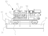
도 1은 본 발명에 따른 압연기의 소재 유도장치의 전체 구성도이다.1 is an overall configuration diagram of a material induction device of a rolling mill according to the present invention.
도 1을 참조하면, 소재 유도장치는 바닥에 설치되는 가이드부(30) 상에 설치되는 이송대차(10)와, 상기 이송대차(10)의 상측에 설치되는 유도부(20)와, 상기 이송대차(10)와 유도부(20) 간에 설치되어 냉각수가 유동되는 냉각부(50)를 포함하여 구성된다.Referring to FIG. 1, the material induction apparatus includes a
상기 이송대차(10)는 판 형상으로 형성되고, 하측에 상기 가이드부(30)를 따라 상기 이송대차(10)가 이송될 수 있도록 하는 바퀴(11)가 결합된다.The
그리고, 상기 이송대차(10)의 상측에는 다수의 유도부가 설치된다.In addition, a plurality of induction parts are installed above the
이러한 상기 이송대차(10)는 상기 가이드부(30)의 일측에 설치된 작동부(40)의 작동을 통해 상기 가이드부(30) 상에서 이송된다.The
도 2는 본 발명에 따른 압연기의 소재 유도장치가 이송되는 것을 나타낸 도면이다.2 is a view showing that the raw material induction device of the rolling mill according to the present invention.
도 2를 참조하면, 상기 작동부(40)는 실린더 형태로 형성되며, 공압 또는 유압으로 동작 될 수 있다.Referring to FIG. 2, the
그리고, 상기 작동부(40)는 모터로 구성되어 기어를 통해 상기 이송대차(10)를 이송 시킬 수 있다.In addition, the
도 3은 본 발명에 따른 압연기의 소재 유도장치의 측면을 나타낸 측면도이고, 도 4는 본 발명에 따른 압연기의 소재 유도장치의 유도부를 확대하여 나타낸 부분 확대도이며, 도 5는 본 발명에 따른 압연기의 소재 유도장치의 유도부에 소재가 유입되는 것을 나타낸 평면도이다.Figure 3 is a side view showing the side of the material guide device of the rolling mill according to the present invention, Figure 4 is an enlarged partial view showing an induction part of the material guide device of the rolling mill according to the invention, Figure 5 is a rolling mill according to the present invention Is a plan view showing that the material is introduced to the induction portion of the material guide device.
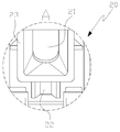
도 3에 도시된 바와 같이 상기 유도부(20)는 상기 이송대차(10)의 상측에 소재(1) 형태와 대응되는 형상으로 유도홈(21)이 형성되고, 이러한 상기 유도홈(21)은 상기 소재(1)의 크기에 따라 각각 다르게 형성된다.As shown in FIG. 3, the
즉, 상기 유도홈(21)의 크기가 각각 다른 유도부(20)가 상기 이송대차(10)의 상측에 다수 설치된다.That is, a plurality of
도 4에 도시된 바와 같이 이러한 상기 유도부(20)는 상기 이송대차(10)와 본체(23)가 결합되고 상기 본체(23)의 상측에 형성되어 상기 소재(1)가 유입되는 유도홈(21)이 형성되며, 상기 유도홈(21)에 돌출되도록 다수의 롤러(22)가 본체(23) 내부에 설치된다.As shown in FIG. 4, the
도 5에 도시된 바와 같이 상기 롤러(22)를 통해 소재(1)가 상기 유도홈(21)을 쉽게 통과 할 수 있다.As shown in FIG. 5, the
상기 냉각부(50)는 상기 이송대차(10)의 상측면에 결합되는 상기 유도부(20)의 하측과 상기 이송대차(10) 간에 형성되며, 상기 냉각부(50) 내부에 냉각수가 유동되어 상기 유도부(20)를 냉각시킨다.The
상기의 본 발명을 좀더 상세하게 설명하면 다음과 같다.The present invention is described in more detail as follows.
본 발명은 압연롤러에서 토출되는 소재(1)가 다음공정으로 유도되는 유도장치의 유도로를 쉽게 변환할 수 있도록 한다.The present invention allows the material (1) discharged from the rolling roller to easily convert the induction furnace of the induction apparatus guided to the next process.
이를 위해 상기 유도장치는 바닥에 가이드부(30)가 설치되고, 상기 가이드부(30) 상측에 이송대차(10)가 설치된다.To this end, the
여기서, 상기 가이드부(30)는 상기 이송대차(10)가 가이드 되도록 길이 방향으로 형성되고, 상기 가이드부(30)의 양단에는 상기 이송대차(10)가 이탈되지 않도록 이탈방지부(31)가 형성된다.Here, the
그리고, 상기 이송대차(10)는 판형상으로 형성되며, 상기 가이드부(30)를 따라 이송되도록 하측에 바퀴(11)가 설치된다.In addition, the
이러한 상기 이송대차(10)는 상기 가이드부(30)의 일측에 설치되는 작동부(40)와 연결되며, 상기 작동부(40)의 작동을 통해 상기 가이드부(30)를 따라 이송된다.The
여기서 상기 작동부(40)는 실린더 형태로 형성되며, 공압 또는 유압으로 동작 될 수 있다.Here, the
그리고, 상기 작동부(40)는 모터로 구성되어 기어를 통해 상기 이송대차(10)를 이송 시킬수 있다.In addition, the
상기 이송대차(10) 상측면에는 다수의 유도부(20)가 설치된다.A plurality of
여기서, 상기 유도부(20)는 유입되는 소재(1)의 종류와 크기에 따라 대응되도록 각각 다른 크기로 형성된다.Here, the
예를 들면 큰 사이즈, 중간 사이즈, 작은 사이즈의 3가지 종류의 소재(1)라면 그 크기에 맞도록 유도홈(21)이 형성된 3종류의 유도부(20)가 상기 이송대차(10) 상측에 결합된다.For example, if three kinds of
이러한 상기 유도부(20)는 상기 이송대차(10)의 상측에 본체(23)가 결합되고, 상기 본체(23)의 상측에 형성되어 상기 소재(1)가 유입되는 유도홈(21)이 형성되고, 상기 유도홈(21)에 돌출되도록 다수의 롤러(22)가 본체(23) 내부에 설치된다.The
상기 유도부(20)와 상기 이송대차(10) 간에는 냉각부(50)가 형성된다.The
이러한 냉각부(50)는 냉각수가 유동되는 관형상으로 형성되고, 상기 냉각부(50)를 통해 유동되는 냉각수로 인해 상기 소재(1)가 유도되는 상기 유도부(20)가 냉각된다.The
상기의 구성을 통해 이루어지는 소재 유도방법은 다음과 같다.Material induction method made through the above configuration is as follows.
소재(1)가 압연롤러에서 토출될때 소재의 종류에 따라 소재(1)를 고정시켜 이동시키도록 이송대차(10)를 소재(1)가 유입되는 위치로 이송시킨다.When the
그리고, 소재(1)의 종류에 맞도록 유도부(20)의 위치를 조정하여 상기 이송대차(10)를 정지시킨다.Then, the
그러면, 상기 이송대차(10)의 유도부(20)에 소재(1)가 유입되고, 상기 유도부(20)에 유입된 소재(1)가 유도부(20)의 롤러를 통해 쉽게 유도부(20)상을 통해 이송된다.Then, the
이때, 상기 소재(1)의 형태에 따라 상기 이송대차(10)의 위치를 변경하여 상기 유도부(20)를 상기 소재(1)에 맞는 형태의 유도부(20)로 변경하게 된다.At this time, by changing the position of the
이와같이 구성된 본 발명은 압연롤러에서 토출되어 다음공정으로 유입되는 소재를 유도할때 이송대차상에 설치된 유도부로 유도하며, 소재의 형태에 따라 유도부를 변경할때 작동부를 통해 이송대차를 이송시켜 유도부의 위치를 변경하므로, 소재를 유도하는 유도부의 변경이 쉽고, 유도부 변경시 발생할 수 있는 안전사고를 방지하는 이점이 있다. The present invention configured as described above is guided to the induction part installed on the transport cart when inducing the material discharged from the rolling roller to the next process, and transfers the transport cart through the operation part when the induction part is changed according to the shape of the material. Since it is changed, it is easy to change the induction part to guide the material, there is an advantage of preventing a safety accident that may occur when changing the induction part.
상기의 본 발명은 바람직한 실시예를 중심으로 살펴보았으며, 본 발명이 속하는 기술분야에서 통상의 지식을 가진 자는 본 발명의 본질적 기술 범위 내에서 상기 본 발명의 상세한 설명과 다른 형태의 실시예들을 구현할 수 있을 것이다. 여기서 본 발명의 본질적 기술범위는 특허청구범위에 나타나 있으며, 그와 비슷한 범위 내에 있는 모든 차이점은 본 발명에 포함된 것으로 해석되어야 할 것이다.
The present invention has been described with reference to the preferred embodiments, and those skilled in the art to which the present invention pertains to the detailed description of the present invention and other forms of embodiments within the essential technical scope of the present invention. Could be. Here, the essential technical scope of the present invention is shown in the claims, and all differences within the similar scope should be interpreted as being included in the present invention.
1 : 소재 10 : 이송대차
11 : 바퀴 20 : 유도부
21 : 유도홈 22 : 롤러
23 : 본체 30 ; 가이드부
31 : 고정부 40 : 작동부
50 : 냉각부1: Material 10: Transfer Balance
11: wheel 20: guide
21: guide groove 22: roller
23:
31: fixed part 40: operating part
50: cooling unit
Claims (7)
상기 이송대차의 상측에 설치되며, 소재가 삽입되어 유도되는 유도부;를 포함하는, 압연기의 소재 유도장치.
It is installed on the upper side of the guide portion, the conveying bogie conveyed along the guide portion through the operation portion; And
Is installed on the upper side of the transfer cart, the induction unit is inserted into the material guide; comprising, the material induction apparatus of the rolling mill.
상기 이송대차와 상기 유도부 간에 형성되어 상기 유도부를 냉각시키는 냉각부;를 더 포함하는, 압연기의 소재 유도장치.
The method of claim 1,
And a cooling unit formed between the transport cart and the induction part to cool the induction part.
상기 냉각부는 관 형상으로 형성되고, 상기 이송대차의 상측면에 결합되는 상기 유도부의 하측과 상기 이송대차 간에 형성되며, 냉각수가 유동되어 상기 유도부를 냉각시키는, 압연기의 소재 유도장치.
The method of claim 2,
The cooling unit is formed in a tubular shape, formed between the lower side of the guide portion and the transfer bogie coupled to the upper side of the transfer bogie, the coolant flows to cool the guide portion, the material induction apparatus of the rolling mill.
상기 이송대차는 상기 가이드부 상에 설치되며, 상기 유도부에 유입되는 소재의 크기에 따라 유도부를 변경하도록 상기 구동부를 통해 이송되는, 압연기의 소재 유도장치.
The method of claim 1,
The transfer cart is installed on the guide portion, and is transferred through the drive unit to change the induction part in accordance with the size of the material flowing into the induction part, the material induction apparatus of the rolling mill.
상기 유도부는 상기 이송대차 상측에 다수 설치되며, 소재의 크기에 따라 상기 소재와 대응되도록 크기가 다르게 형성되는, 압연기의 소재 유도장치.
The method of claim 1,
The guide part is installed a plurality of the upper side of the transfer cart, the size is formed differently to correspond to the material according to the size of the material, the material induction apparatus of the rolling mill.
상기 유도부는 상측과 길이방향 양단이 개방되며, 소재가 유입되는 유도홈;
상기 유도홈의 하측에 형성되어 상기 소재의 이동이 쉽도록 다수 설치되는 롤러; 및
상기 롤러가 고정되는 본체를 포함하는, 압연기의 소재 유도장치.
The method of claim 1,
The guide portion is open at both ends of the upper side and the longitudinal direction, the guide groove into which the material flows;
Rollers are formed on the lower side of the guide groove is installed in a number of easy to move the material; And
Including the main body is fixed to the roller, the material induction apparatus of the rolling mill.
상기 롤러는 소재가 유도되도록 상기 유도홈의 상측으로 상기 롤러의 일부가 돌출되어 상기 본체에 결합되는, 압연기의 소재 유도장치.The method according to claim 6,
The roller is a part of the roller protrudes to the upper side of the guide groove so that the material is guided, the material induction apparatus of the rolling mill.
Priority Applications (1)
| Application Number | Priority Date | Filing Date | Title |
|---|---|---|---|
| KR1020100138063A KR20120076076A (en) | 2010-12-29 | 2010-12-29 | Inducing apparatus for materials of rolling mill |
Applications Claiming Priority (1)
| Application Number | Priority Date | Filing Date | Title |
|---|---|---|---|
| KR1020100138063A KR20120076076A (en) | 2010-12-29 | 2010-12-29 | Inducing apparatus for materials of rolling mill |
Publications (1)
| Publication Number | Publication Date |
|---|---|
| KR20120076076A true KR20120076076A (en) | 2012-07-09 |
Family
ID=46709857
Family Applications (1)
| Application Number | Title | Priority Date | Filing Date |
|---|---|---|---|
| KR1020100138063A KR20120076076A (en) | 2010-12-29 | 2010-12-29 | Inducing apparatus for materials of rolling mill |
Country Status (1)
| Country | Link |
|---|---|
| KR (1) | KR20120076076A (en) |
-
2010
- 2010-12-29 KR KR1020100138063A patent/KR20120076076A/en not_active Application Discontinuation
Similar Documents
| Publication | Publication Date | Title |
|---|---|---|
| JP5266380B2 (en) | Method and apparatus for casting, rolling and complex equipment | |
| KR101417230B1 (en) | Batch and Endless Rolling System and Method | |
| EP2412460B1 (en) | Apparatus and method for production of metal elongated products | |
| CN101365918A (en) | Roller hearth furnace for heating and/or temperature equalisation of steel or steel alloy continuous cast products and arrangement thereof before a hot strip final rolling mill | |
| KR101781076B1 (en) | Steel plant for the production of long metal products and corresponding production method | |
| CN103624081B (en) | The intermediate mill region of casting rolling equipment complex | |
| CN104540606A (en) | Method and device for a combined continuous casting and rolling system | |
| ES2628833T3 (en) | Method and apparatus for continuous lamination | |
| CN102345008B (en) | Temperature maintenance and/or heating apparatus for long metal products and relative method | |
| KR20120076076A (en) | Inducing apparatus for materials of rolling mill | |
| RU2640484C1 (en) | Method and device for manufacturing metal strip by continuous casting method combined with rolling | |
| CN106734212A (en) | A kind of double-core axle cooling of tandem rolling tube machine, lubricating arrangement | |
| KR101225256B1 (en) | apparatus and method for cutting continous casting product | |
| KR101399877B1 (en) | Cooler for rolling mill | |
| BRPI1003247A2 (en) | continuous casting and rolling method and installation for preparing long rolled metal products | |
| JP4757708B2 (en) | Steel plate manufacturing equipment | |
| CN113396022B (en) | Apparatus and method for producing a strip | |
| KR200460060Y1 (en) | Guide Apparatus for Steel Reinforcement Rolling | |
| KR101051295B1 (en) | Hot Rolling Equipment | |
| KR101225401B1 (en) | tilting table for tung disposition | |
| US20240009724A1 (en) | Process and apparatus for producing metallurgical products, in particular of the merchant type, in particular in an endless mode | |
| KR100572644B1 (en) | Method and apparatus for temporarily interrupting the passage of long products between upstream and downstream paths in a rolling mill | |
| CN203648999U (en) | Synchronous unloading mechanism for transferring of section steel | |
| KR101310830B1 (en) | Transferring apparatus for rolling mill | |
| KR20110121017A (en) | Jig for crane which moves material |
Legal Events
| Date | Code | Title | Description |
|---|---|---|---|
| A201 | Request for examination | ||
| E902 | Notification of reason for refusal | ||
| E601 | Decision to refuse application |